Embed Size (px)
Citation preview
SUNSET Sustainable Social Network Services for Transport
www.sunset-project.eu
Grant agreement n°: 270228 Start date: Feb 1, 2011
Duration: 36 months Area: ICT for Transport
Project Officer: Mr. Stefanos Gouvras
Deliverable D5.1 “Service Framework Architecture & Design”
Version: Final Due date of deliverable: Nov 25, 2011 Actual submission date: Nov 25, 2011
Dissemination level: PU Responsible partner: QMUL
© 2011-2014 SUNSET Consortium The research leading to these results has received funding from the European Union Seventh Framework Programme (FP7/2007-2013) under grant agreement n° 270228. The project’s website is at www.sunset-project.eu.
Page 2 of 39
Summary This deliverable specifies the SUNSET system’s internal components and 3rd party external components that need to be integrated to the SUNSET system. The SUNSET system is comprised of the following subs-systems: mobile client; Web portal (user); dashboard (manager Web portal); proxy & security services; mobility services LL evaluation support; incentive services and external resource adapters. Each of these sub-systems comprises one or more individual system components. Each of these system components enacts one or more specific services. Exemplar interactions between these system components such as mobility pattern detection, incentive distribution, identity and privacy and Living Lab control and evaluation are defined. In addition, a deployment overview is presented in a bid to understand and foresee both the technical challenges related to the support of multiple cities/LLs, hosting and the relation with the i-Zone project system that acts as a precursor for the SUNSET system. Finally, a single deployment plan that is shared between all the living labs is proposed.
Page 3 of 39
Document Information Authors Name Partner Email Koen Jacobs LOCNET [email protected] Stefan Poslad QMUL [email protected] Thomas Oshin QMUL [email protected] Zhenchen Wang QMUL [email protected] Arjan Peddemors NOVAY [email protected] Peter Ebben NOVAY [email protected] Johan Koolwaaij NOVAY [email protected] Marko Luther DOCOMO [email protected]
Editor Name Stefan Poslad Partner QMUL Address School of Electronic Engineering & Computer Science (EE), Queen Mary,
University of London, UK Phone +44 2078823754 Fax Email [email protected]
History
Version Date Changes V0.0 00-00-2011 Table of contents V0.1 00-00-2011 Updated the table of contents V0.2 00-00-2011 Added the overall architecture that was iteratively and jointly
developed during the 2011-05 Munich project meeting. V0.3.1 17-06-2011 Review & consolidated edits to date. Many contributions added
overall, e.g., Improved design approach to add a discussion about architectural styles and about some specific design issues such as security. Started some system interaction designs in section 4. Enhanced the deployment issues and included something about non-functional requirements. Add section about external resources, reorganised internal components classification, sunset systems reuse from I-Zone specified.
V0.3.2 24-06-2011 Updated classification of components, described relations with i-Zone, updated references, textual changes
V0.3.3 10-08-2011
Updated classification of components, arch overview, added example interaction patterns for some common use-cases. Edited many sections to correct references and for consistency
V0.3.4 30-08-2011 Updated use-cases V0.3.5 30-09-2011 Updated relations with i-Zone; textual changes throughout the
document V0.3.6 11-10-2011 Added report introduction, related documents, reference chapter, V0.4.0 17-10-2011 Edits throughout to progress document for WP5 review V0.4.1 26-10-2011 Merged in component API doc, removed some redundant sections, V0.5.0 05-11-2011 Added missing APIs / descriptions of WP5 components V0.6.1 10-11-2011 Final edits by task leader before project level review

Page 4 of 39
V0.7.1.5 23-11-2011 Edits by task leader to respond to project level review comments V1.0 30-11-2011 Final version, approved by PCPs and PMT, sent to EC
Distribution Date Recipients Email 25-11-2011 SUNSET partners [email protected] 25-11-2011 Project Officer [email protected] 25-11-2011 Project Archive [email protected]

Page 5 of 39
Table of Contents 1. Introduction ......................................................................................... 7
1.1 GOALS ................................................................................................................................................. 7 1.2 MAIN RESULTS AND INNOVATIONS .......................................................................................................... 7 1.3 APPROACH .......................................................................................................................................... 7
2. System Architecture ........................................................................... 9
2.1 SYSTEM ARCHITECTURAL VIEWPOINTS AND PATTERNS USED ...................................................................... 9 2.2 SYSTEM ARCHITECTURE AND COMPONENTS OVERVIEW ......................................................................... 11 2.3 MOBILE CLIENT ................................................................................................................................... 14
2.3.1 Mobile Experience Sampler (MES) ..................................................................................................... 14 2.3.2 Mobile Incentive Presenter (MIP) ....................................................................................................... 14 2.3.3 Mobile Mobility Profile Visualisation (MMPV) .................................................................................. 14 2.3.4 Mobile Buddy List (MBL) .................................................................................................................... 14 2.3.5 Mobile Notifications (MN) ................................................................................................................... 14 2.3.6 Mobile Authentication (MA) ................................................................................................................ 14 2.3.7 Mobile Sensing (MS) ............................................................................................................................ 15
2.4 (USER) WEB PORTAL ........................................................................................................................... 15 2.4.1 User & Application Management (UAM) ............................................................................................ 15 2.4.2 Portal Profile Visualisation (PPV) ...................................................................................................... 15
2.5 DASHBOARD (MANAGER WEB PORTAL) .............................................................................................. 15 2.5.1 Living Lab Control & Evaluation (LLCE) ........................................................................................... 15
2.6 PROXY & SECURITY SERVICES ............................................................................................................... 16 2.6.1 Privacy Manager (PM) ........................................................................................................................ 16 2.6.2 Relation and Identity Manager (RIM) ................................................................................................. 16 2.6.3 Proxy & Authentication (PA) ............................................................................................................... 16
2.7 MOBILITY SERVICES .............................................................................................................................. 16 2.7.1 Personal Mobility Store (PMS) ............................................................................................................ 16 2.7.2 Mobility Pattern Detector (MPD) ........................................................................................................ 16 2.7.3 Mobility Pattern Visualizer (MPV) ...................................................................................................... 16 2.7.4 Traffic Pattern Detector (TPD) ........................................................................................................... 17
2.8 LL EVALUATION SUPPORT ..................................................................................................................... 17 2.8.1 Experience Sampling Store (ESS) ........................................................................................................ 17 2.8.2 Evaluation Support (ES) ...................................................................................................................... 17
2.9 INCENTIVE SERVICES ............................................................................................................................ 17 2.9.1 Incentives Market Place (IMP) ............................................................................................................ 17 2.9.2 Incentive Simulation Environment (ISE).............................................................................................. 17
3. External Resource Adapters ............................................................ 18
3.1 SOCIAL NETWORK ADAPTER (SNA) ..................................................................................................... 18 3.2 INFRASTRUCTURE NETWORK MANAGER (INM) ...................................................................................... 18 3.3 INFRASTRUCTURE STATUS STORE (ISS) .................................................................................................... 18 3.4 WEATHER INFORMATION ADAPTER (WIA) ............................................................................................ 18
4. Service Interaction ........................................................................... 19
4.1 MOBILITY PATTERN DETECTION INTERACTION ......................................................................................... 19 4.2 INCENTIVES DISTRIBUTION INTERACTION ................................................................................................. 20 4.3 IDENTITY AND PRIVACY INTERACTION .................................................................................................... 21 4.4 LL CONTROL & EVALUATION INTERACTION ........................................................................................... 22
Page 6 of 39
5. Deployment Overview ..................................................................... 23
5.1 DEPLOYMENT ISSUES ............................................................................................................................ 23 5.1.1 Supporting Multiple Cities or LLs ....................................................................................................... 23 5.1.2 Hosting ................................................................................................................................................. 23 5.1.3 Relation with i-Zone............................................................................................................................. 24
5.2 DEPLOYMENT OUTLINE ......................................................................................................................... 25 5.3 DEPLOYMENT PROCESS AND STAGING .................................................................................................. 26
6. Conclusions ....................................................................................... 28
7. References ........................................................................................ 29
Appendix A ............................................................................................. 30
A.1 SUNSET COMPONENT OVERVIEW ............................................................................................................... 30 A.2 WP5 COMPONENTS .................................................................................................................................. 30
A.2.1 Infrastructure Network Manager .............................................................................................................. 30 A2.2 Infrastructure Status Store ......................................................................................................................... 31 A2.3 Traffic Pattern Detector ............................................................................................................................ 33 A2.4 Proxy & Authentication ............................................................................................................................. 33 A2.5 Living Lab Controls & Evaluation (Dashboard) ....................................................................................... 34 A2.6 Web Portal (User)...................................................................................................................................... 35
A.3 SYSTEM REQUIREMENTS FOR WP5 COMPONENTS ......................................................................................... 36 A.3.1Infrastructure Network Management ......................................................................................................... 36 A.3.2 Infrastructure Status Store ........................................................................................................................ 36 A3.3 Traffic Pattern Detector ............................................................................................................................ 37 A3.4 Proxy & Authentication ............................................................................................................................. 37 A3.5 Living Lab Controls & Evaluation (Dashboard) ....................................................................................... 38 A3.6 Web Portal (User)...................................................................................................................................... 39

Page 7 of 39
1. Introduction This deliverable gives a technical description of SUNSET system architecture in terms of its internal components and external resources (the ones that exist outside the SUNSET system and are managed by third parties), e.g., weather data feeds, map data etc. It also gives a description of the interactions between components. The report aims to drive the integration of existing and new components into a single system capable of supporting the operation of the city-wide Living Labs (LL) where the SUNSET system is to be deployed.
1.1 Goals The goals of this deliverable are to:
• Specify the design of a framework that links all existing components delivered by WP2-WP4, as well as 3rd party services.
• Specify a few additional WP5 components that are needed to manage and to access the system.
1.2 Main Results and Innovations The main results of this document are given in Table 1. This explains how the results of this deliverable contribute to the project’s main innovations. In this table, “N/A” in the right column indicates that this deliverable does not contribute to a particular project innovation.
SUNSET innovations Contribution of this deliverable Social mobility services that motivate people to travel more sustainably in urban areas
A social network adapter is specified to enable a social networking incentive that motivates mobile users to acquire and update mobility information via social networks.
Intelligent distribution of incentives to balance system and personal goals
An overview of how the incentives are used in the system is described for the incentive distribution service
Algorithms for calculating personal mobility patterns using info from mobile and infrastructure sensors
N/A
Evaluation methodologies and impact analysis based on living lab evaluations
An overview of the LL control and evaluation service interaction is described. A single deployment strategy is proposed that can be shared between all the living labs. This strategy will ease and standardise the evaluations across LLs
Table 1: Contributions of this deliverable, D5.1, to the SUNSET innovations
1.3 Approach The main objective of this deliverable is to describe SUNSET system components and interactions between these components. Finally, a deployment overview is presented to foresee the technical challenges in doing this.
Page 8 of 39
Two main types of components are considered as follows: − The system’s internal components (Section 2); − The 3rd party or external resources to be integrated to SUNSET system (Section 3).
Four main exemplar system interactions between components are defined (Section 4): − Mobility pattern detection − Incentive distribution − Identity and privacy − LL control & Evaluation.
The complexity of component deployment is then analysed in terms of multiple cities/LLs support, hosting and the relation with the i-Zone project system that precedes it. (Section 5)
Page 9 of 39
2. System Architecture The high-level design of the architecture as a distributed system is based upon a client-proxy-server model. The main sub-systems that comprise the overall system are a mobile client, Web portal for users, dashboard for managers, proxy and security services, mobility monitoring services, LL evaluation support services, incentive services and external information resource adapters. Each of these sub-systems comprises one or more individual system components that enact a specific service. Each of these is defined in turn in the following sections.
2.1 System Architectural Viewpoints and Patterns Used Architectural viewpoints describe an abstraction of a model, sometimes specific to a specific stake-holder such as end-user, system developer and operational manager, network manager etc. Architectural patterns are conceptual models that capture the organisation of the essential components of an ICT system architecture and their interrelationships. A component-based design and implementation supports two key properties for the system: high cohesion within components such that they perform well-defined functions and loose coupling between components that minimise undesired side-effects, e.g., the unavailability of the component that stores personal mobility info. The system can be designed to prevent the latter type of system disruption, i.e., a delayed-write strategy can be used to add the newly acquired information to the store when it becomes available. Design patterns heavily determine the main components and define the main ways in which these components interact. Poslad [2009] has identified a number of standard candidate architectural styles, based upon an extension of original work of Garlan and Shaw [1993]. The SUNSET system can be organised as a three-tier system consisting of a client (front-end), middleware and servers (back-end). Middleware can be either front-end, when acting as proxies, or backend when acting as servers. The client sub-system (i.e., an organisation of a group of system components to fulfil a common purpose) focuses on providing system access to the human users of the system via an access device. Mobile end-users tend to use lighter-weight fat-client (in terms of the ICT resources in the device) such as smartphones while on the move. They may also use mid-weight fat-client devices such as laptops (that have more ICT resources) to interact with the SUNSET system, via its Web portal, at fixed locations such as home and office. SUNSET system operational managers will likely use a fat-client server design to access and manage the SUNSET system via a component called the Dashboard, accessed on a laptop or PC. Unlike a thin-client, such as pure Web-browser type design, a fat-client tends to make substantive use of resources on access devices, such as sensors to sense mobility, processing to pre-filter sensed data and storage to aggregate sensed data before uploading it in order to optimise communication. In a service-oriented computing model, each hardware system component supports services, e.g., sensors perform data acquisition services, user interfaces support information presentation and interaction services. The server (comprised of sub-systems) defined supports services such as mobility pattern detection, mobility pattern visualisation. There are two main purposes for the use of middleware. First, middleware seeks to ‘factor’ out common services that can be used across heterogeneous applications within the same domain and across heterogeneous domains. Second, it seeks to be a mediator between servers and clients. The SUNSET system consists of a set of heterogeneous components, working together in a distributed configuration. A component can be a service component, residing in the SUNSET service environment, or a client component running on the mobile, internet-enabled phones of SUNSET users. A service component is either a front end component serving requests from clients, or a back end component delivering functionality to other service components. Additionally,
Page 10 of 39
the SUNSET system uses resources offered by external or 3rd party components that are not themselves part of the SUNSET system, e.g., sensors and services to monitor road traffic. Users interact with the system through application(s) on their mobile phone, or by using a regular web browser (see Figure 1). A hybrid distributed system interaction style is used by SUNSET to support loose-coupling between system components. SUNSET combines the use of Representation State Transfer (REST) Models, Shared Data Repository (SDR) and Event-Driven Architectures (EDA) for different parts of the system. Different kinds of state information can be exchanged as metadata when one process invokes another. In the Representation State Transfer (REST) model (Fielding, 2000), the receiver is seen as a set of resources identified by URLs. Loose-coupling is supported in that only representations of the resources are exchanged, not any state information. This can for example be used to support the experience sampling interaction. In a SDR, data producers store data and can be operated independently from data consumers that can modify and read the data, e.g., mobility sensing can act independently from mobility pattern detection. In an EDA, events are generated by event producers. They are gathered and distributed by an event dispatcher to any event consumer that wants to be notified of them. The event consumer can perform its own checks so that events meet certain constraint conditions and if they do, one or more actions or services are triggered. The event producers are loosely coupled from the event consumers.
Page 11 of 39
2.2 System Architecture and Components Overview
Third Parties
Back End
System Status, behaviour
overviews
Mobility Services
External Resource
Adaptation
LL Evaluation
SupportIncentivesServices
Mobility Profile, Info. feeds
Info. feeds
Incentives
Front End
Dashboard
Mobility profile, incentives
Social Networks, traffic sensors,Maps. GIS, Service offers
Sensed user inputs, e.g., location etc. User
Web Portal
Incentives
Mobility profile, Info. feeds
Proxy & SecurityServices
LL NetworkMobility
Manager
Mobile client
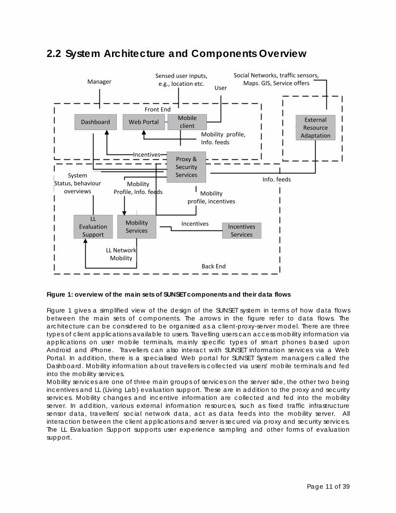
Figure 1: overview of the main sets of SUNSET components and their data flows Figure 1 gives a simplified view of the design of the SUNSET system in terms of how data flows between the main sets of components. The arrows in the figure refer to data flows. The architecture can be considered to be organised as a client-proxy-server model. There are three types of client applications available to users. Travelling users can access mobility information via applications on user mobile terminals, mainly specific types of smart phones based upon Android and iPhone. Travellers can also interact with SUNSET information services via a Web Portal. In addition, there is a specialised Web portal for SUNSET System managers called the Dashboard. Mobility information about travellers is collected via users’ mobile terminals and fed into the mobility services. Mobility services are one of three main groups of services on the server side, the other two being incentives and LL (Living Lab) evaluation support. These are in addition to the proxy and security services. Mobility changes and incentive information are collected and fed into the mobility server. In addition, various external information resources, such as fixed traffic infrastructure sensor data, travellers’ social network data, act as data feeds into the mobility server. All interaction between the client applications and server is secured via proxy and security services. The LL Evaluation Support supports user experience sampling and other forms of evaluation support.

Page 12 of 39
These clients, services and proxy sub-systems are comprised of individual system components (see Table 2) at a lower level. They are described in more detail in later parts of Section 2 and Section 3. Sunset Sub-systems System Components Mobile Client Mobile Experience Sampler, Mobile Incentive Presenter, Mobile
Mobility Profile Visualisation, Mobile Buddy List, Mobile Notifications Mobile Authentication, Mobile Sensing
Web Portal (User) User & Application Management, Portal Profile Visualisation Dashboard (Manager Web Portal)
Living Lab Control & Evaluation
Proxy & Security Services Privacy Manager, Relation and Identity Manager, Proxy & Authentication
Mobility Services Personal Mobility Store, Mobility Pattern Detector Mobility Pattern Visualizer, Traffic Pattern Detector
LL Evaluation Support Experience Sampling Store, Evaluation Support Incentive Services Incentives Market Place, Incentive Simulation Environment External Resource Adapters
Social Network Adapter, Infrastructure Network Manager, Infrastructure Status Store, Weather Information Adapter
Table 2: Classification of the main SUNSET System components A more detailed architectural viewpoint of the SUNSET system is given in Figure 2. This focuses on how SUNSET components relate to the organizational roles of the consortium within SUNSET. This viewpoint of the system highlights the server-side components and specific interfaces. It does not show all component interfaces for the mobile client-side in order to prevent the figure from being too cluttered. The majority of components will be implemented by WP2 (Mobility server) and WP4 (Mobility client). To create a fully functional system capable of supporting the living lab operation, WP5 will also build a number of components, e.g., for Operational Management. The components to enable user feedback to be used to evaluate the system will be defined by WP6 and / or WP7. Additionally, WP3 will deliver a component for incentives. WP5 integrates all internal SUNSET components and can interoperate with external resources. Some of the components are based on existing functionality, e.g., from i-Zone1
5.1.3, that are adapted to suit
SUNSET’s needs (see Section ).
1 The I-Zone website is http://www.novay.nl/projecten/i-zone/7619 but the content is only currently available in Dutch.

Page 13 of 39
Figure 2: SUNSET components, their interrelationships, and work package division Note in Figure 2, the emphasis is on services thus databases are not indicated at this high-level. Some components from their name imply that they are a type of information storage and retrieval service, e.g., the Personal Mobility store or PMS. Furthermore, such components as the PMS are not just a dumb data store, but also have functionality and intelligence of their own. Note also that the proxy is depicted to show its authentication purpose. In reality it also does a redirect from a central access point to all server-side components. This is not drawn in this figure because otherwise this results in a spider figure with all interaction going via the proxy and them being hard to distinguish from each other However, this redirection by the proxy is indicated in
Enforce privacy
on all APIs
Web portal(for users, developers, and
living lab controllers)
Mobile sensing (T4.1)
Personal Mobility Store (PMS) (T2.1)
Mobility Pattern Detector (MPD)
(T2.2)
Mobility Pattern Visualizer (MPV)
(T2.2)
Incentives Market Place (IMP) (T2.4)
Experience Sampling Store
(ESS) (T2.1)
Evaluation Support (ES) (T2.4)
Privacy Manager (PM) (T2.3)
Relation and Identity Manager
(T2.3)
Infrastructure Network Manager
(T5.2)
Incentives API (T2.4)
Social Networks
Relation, Identity and Privacy API
(T2.3)
Infrastructure Network API (T5.2)
Mobility Pattern API (T2.2)
Experience Sampling API
(T2.1)
Evaluation API (T2.4)
Resolve geo-location traces into infrasegments & POI lookup
Actual (anonymous) mobility overviews
Specify xp samples in terms of personal patterns and data
Portal profile visualisation (T2.2)
Show simple personal profile
or buddy list
Present incentives and overviews
to the user
Pose questions, polls
Living Lab Control & evaluation
(dashboard) (T5.2)
Get living lab behaviour overviews
Get community overviews
Feed relations
Show personal profile widget
Show interactive personal profile
Measurement API (T2.1)
Incentive simulation
enviroment (ISE) (T3.3)
Get relations for buddy view
Mobile experience sampler (T4.1)
Mobile mobility profile
visualisation (T4.2)
Mobile incentive presenter (T4.3)
Mobile authentication
(T4.2)
Mobile buddy list (T4.2)
Infrastructure Status Store (ISS)
(T5.2)
Mobile notifications (T4.1)(coming from EES, IMP or MPD)
Proxy & authentication
(T5.2)
Traffic API (T5.2)
Traffic Pattern Detector (TPD)
(T5.2)
WP2 APIWP3 WP4
WP5
Get impact overviews, add & play with incentives
Mobile application(for travelling users)
See answers, add questions
Authenticate mobile user
Specify incentives in terms of personal patterns, user profiles and traffic data
WP2
WP5 API
Incentive templates
Register & profile user
External components
Pattern detectionExperience sampling
Incentives
WP division Interaction lines
Living lab control & evalIdentity & privacy
Add ad hoc relations
Weather and more...
Infrastructure sensors
Get weather
Get infrastructure data
Map source
Mobility Visualization API
(T2.2)
User & app management
(T2.3)
(Due to limited space, only the main interaction is described)
Present incentive (overviews)
Current network status & patterns
Trigger sampler
Trigger incentive
Trigger sensor controller
Report city status updates in public
Get user profile
Page 14 of 39
other less complex figures such as the system overview (Figure 1) and in the interaction overviews (Figure 3, Figure 4, Figure 5 and Figure 6).
2.3 Mobile Client This subsection describes the components that together form the Mobile (access device) Client used by the core stake-holder, end-user or traveller (referred to as the user for shorter). In Figure 2 of the previous section, these components are marked as the red elements.
2.3.1 Mobile Experience Sampler (MES) The Mobile Experience Sampler (MES) retrieves questions posed by system operators from the ES (Evaluation Support, section 2.8.2) and ESS (Experience Sampling Store, section 2.8.1) components to mobile users. It presents these questions at appropriate times to users based on the currently sensed and interpreted situation, e.g. stationary or traveling and sends the answer back to the platform.
2.3.2 Mobile Incentive Presenter (MIP) The Mobile Incentive Presenter (MIP) provides the mobile interface of the IMP (Incentive Market Place, section 2.9.1). It presents incentives to the user and sends the users responses and acceptances back to the IMP. The communication between the MIP and the IMP utilises the Mobile Notifications mechanism (MN, section 2.3.5).
2.3.3 Mobile Mobility Profile Visualisation (MMPV) The Mobile Mobility Profile Visualisation (MMPV) component provides the mobile front end to the MPV (Mobility Pattern Visualizer, section 2.7.3) to allow the user to inspect relevant mobility patterns that are detected. In addition, the MMPV provides direct feedback of the gathered mobility data in the form of traces and place indicators on a map to the user.
2.3.4 Mobile Buddy List (MBL) The Mobile Buddy List (MBL) collects and displays profiles, status and performance summaries of a user’s buddies (such as their frequent places, current travel status and activities, CO2 performance, incentive status) identified by the Relation and Identity Manager (RIM, section 2.6.2) that are authorised by the Privacy Manager (PM, section 2.6.1) from the PMS (Personal Mobility Store, section 2.7.1), MPD (Mobility Pattern Detector, section 2.7.2) and IMP (Incentives Market Place, section 2.9.1).
2.3.5 Mobile Notifications (MN) The Mobile Notifications component receives notifications from the SUNSET platform coming from the Experience Sampling Store (ESS, section 2.8.1), Incentives Market Place (IMP, section 2.9.1) or Mobility Pattern Detector (MPD, section 2.7.2) and dispatches them to the mobile client component responsible for processing a given type of notification. As such this component allows the platform to send messages to the mobile users or the mobile application for example to influence the location-sampling rate based on historical information computed on the server-side.
2.3.6 Mobile Authentication (MA) The Mobile Authentication component registers the mobile application and the mobile device for the mobile user via the Proxy & Authentication (PA, section 2.6.3) as well as the RIM component (Relation and Identity Manager, section 2.6.2) and authorises the application to

Page 15 of 39
make API calls to the platform. This requires explicit consent of the users during setup. As a result the corresponding credentials are securely stored on the mobile device that allows access via encrypted communication to the platform.
2.3.7 Mobile Sensing (MS) The Mobile Sensing (MS) component gathers raw measurements from built-in mobile device sensors as well as externally connected sensors. In a pre-processing step, it applies algorithms to reduce the noise and size of the gathered data, to recognise stationary and travelling situations, and computes initial trip modalities based on the gathered data and the type of the corresponding sensor source. The MS activates, deactivates and adjusts the available sensors and the sampling rates to optimise energy consumption as well as data quality. The MS stores sampled data on the device to the extent needed to fulfil its tasks and sends it to the PMS (Personal Mobility Store, section 2.7.1).
2.4 (User) Web Portal 2.4.1 User & Application Management (UAM) The User & Application Management (UAM) component provides the front-end of the RIM (section 2.6.2) to users and developers. It allows developers to register external resources and applications together with a specification of the required access patterns and individual users to grant and revoke registered external resources and applications with respect to specified access rights. This component also presents user preferences and settings to users and supports the extension and modification of the corresponding entries.
2.4.2 Portal Profile Visualisation (PPV) The Portal Profile Visualisation (PPV) component provides the front-end of the web portal for the users of the SUNSET system. The PPV provides visualisations of user mobility profiles as generated by the Mobility Visualisation API. In addition, it links the personal mobility information of one owner user to friends on social networks. The PPV and the mobile client may use the same data for visualisation. However, the PPV can provide more elaborate and comprehensive visualisations, as it does not have the screen limitations of a mobile device.
2.5 Dashboard (Manager Web Portal) 2.5.1 Living Lab Control & Evaluation (LLCE) The Living Lab Control & Evaluation (LLCE) component serves as a dashboard for the living lab city and SUNSET management teams to monitor the flow of data in the SUNSET system by means of a number of visualisations (e.g., usage statistics, behaviour overviews) and analysis tools (e.g., effectiveness of incentives, results of experience sampling services). In such way, the management teams provide an easy-interpretable and live overview of the status of the system as it is running in the living lab city. Furthermore, the LLCE can automatically publish overviews to social networks such that users can observe the daily impact of the SUNSET system. In addition, this is where city level objectives and challenges can be designed and issued by an operator, e.g., ‘Most green traveller of this month in this area receives a reward’.

Page 16 of 39
2.6 Proxy & Security Services 2.6.1 Privacy Manager (PM) The Privacy management component manages the privacy policies of the user. Those policies are formulated based on social relations managed by the Relation and Identity Manager (RIM, section 2.6.2) or ad-hoc groupings computed by the MPD (Mobility Pattern Detector, section 2.7.2). It then decides on the access to the mobility data when asked by the policy enforcement point of a personal data handling components such as the MPD or the PMS.
2.6.2 Relation and Identity Manager (RIM) The Relation and Identity Manager (RIM) provides its own social network implementation that contains a copy of the social network data from existing social networks like Facebook. The data is imported through a component that is responsible for importing and exporting social network data.
2.6.3 Proxy & Authentication (PA) The Proxy & Authentication (PA) component is responsible for connecting the SUNSET core platform to external resources and applications in a secure way. It ensures proper authentication according to user and application credentials and encrypted communication with remote components. It potentially provides caching and load balancing services to improve the overall system performance.
2.7 Mobility Services 2.7.1 Personal Mobility Store (PMS) The Personal Mobility Store (PMS) collects all raw measurements from the mobile client, and provides methods to enrich these measurements for the purpose of pattern detection and experience sampling. It also provides feedback to the client (in terms of recommended changes in sensor settings) based on the analysis of the raw measurements.
2.7.2 Mobility Pattern Detector (MPD) The Mobility Pattern Detector (MPD) receives data from the mobility monitoring components, such as the PMS (Personal Mobility Store, section 2.7.1) plus external sources, and uses sophisticated algorithms to detect patterns for individuals, groups, places, regions, routes or vehicles such as bus lines or a taxi. The MPD offers intelligent cross sections of the mobility data of the individual, based on derived data. This component works incrementally, adding and deriving new pieces of mobility data to the persistent mobility data set while re-using existing data to improve the results.
2.7.3 Mobility Pattern Visualizer (MPV) The Mobility Pattern Visualizer (MPV) takes the patterns derived by the Mobility Pattern Detector (MPD, section 2.7.2) and turns them into interpretable and easily accessible visualisations. Those visualisations include: long-term perspectives (e.g., over the past year) together with the personal or ecological consequences that would have resulted if other mobility choices would have been made; trend watching that allows to detect trends and changes in mobility behaviour, as well as visualisations that indicates the personal, city-wide or place oriented performance on goals. The visualisations provided by this component are made available via
Page 17 of 39
the SUNSET portal, also via social networks, in order to reach people outside the SUNSET community.
2.7.4 Traffic Pattern Detector (TPD) The Traffic Pattern Detector (TPD) component processes the infrastructure data from the Infrastructure Status Store (ISS, section 3.3). This component provides a number of services to compute traffic patterns by combining data sources for the use of travel time estimation. The output of the TPD is combined with mobility patterns and user profiles to formulate incentives towards the user.
2.8 LL Evaluation Support This subsection describes the Living Lab Evaluation-specific server-side components of the SUNSET system.
2.8.1 Experience Sampling Store (ESS) The Experience Sampling Store (ESS) allows researchers to register questions for a specific target group in certain context conditions. It provides the web portal with a set of possible constraints and provides the PMS with rules constructed by researchers. The ESS triggers the presentation of questions towards users via the Mobile Experience Sampler component (MES, section 2.3.1) in case the corresponding conditions are fulfilled.
2.8.2 Evaluation Support (ES) The Evaluation Support (ES) component collects and collates information from other system components for the preparation of performance evaluation of the overall system. It processes the gathered data according to pre-defined indicators and formats, to be presented via the Living Lab Control and Evaluation component (LLCE, sect. 2.5.1) to the operators.
2.9 Incentive Services 2.9.1 Incentives Market Place (IMP) The Incentives Market Place (IMP) provides a platform to offer incentives in the form of reward, recognition and real-time feedback to users to encourage travellers to improve their travel behaviour with respect to the system’s and an individual’s travel objectives. The IMP implements algorithms that match available incentives with mobility information from the MPD, individual user preferences and general transport information. It identifies users whose travel behaviour ought to be changed and the segments of the journey that could be optimised as well as users who are likely to react more positively on being offered incentives and thus are more likely to change their behaviour. It is responsible for offering the most appropriate incentive at the most appropriate moment to users via a mobile client (section 2.3.2). The IMP also records a users’ response to the incentive offers and calculates the overall participation rates. Via APIs, incentive providers can register and publish incentives via the IMP.
2.9.2 Incentive Simulation Environment (ISE) The Incentive Simulation Environment (ISE) provides an environment to test the effectiveness of incentives on historic data in the SUNSET system. In such a way, both stakeholders and developers can investigate how the conditions defining an incentive can be optimised to target the users they wish to address without introducing them to the system just yet.
Page 18 of 39
3. External Resource Adapters Several information resources are considered to exist outside and to be external to the SUNSET system. SUNSET includes resource adapters to incorporate these within SUNSET. Most of these adapters are localised/location-specific such as the Infrastructure Sensor Network Manager and Weather Information Adapter.
3.1 Social Network Adapter (SNA) The Social Network Adapter interfaces with several well-known social networks, in order to facilitate user registration based on existing accounts to provide services to share information, such as successfully completing an incentive, with others, and to bootstrap the process of creating a buddy list by importing contacts from existing social networks.
3.2 Infrastructure Network Manager (INM) The Infrastructure Network Manager (INM) provides a collection of services allowing access to road networks and their characteristics, public transport information, transport routing services and other geographical data, such that personal mobility information can be mapped to these information sources. The ISS provides persistence for the INM.
3.3 Infrastructure Status Store (ISS) The Infrastructure Status Store (ISS) component connects to external data sources to collect and prepare traffic-related data for the Traffic Pattern Detector (TPD, section 2.7.4). Examples of these data are road works, traffic jams, speed traps and travel times for the purpose of routing and travel time prediction. These are situated in the external resource adaptation sub-system because fixed transport network sensors are envisioned to be different for every Living Lab, even although a common adapter model is used to integrate these sources into the SUNSET system.
3.4 Weather Information Adapter (WIA) The Weather Information Adapter (WIA) interfaces with external weather information providers to provide current, forecasted, and perhaps historical weather information for a given location. This information will be used by the SUNSET platform to annotate trips, but also to provide appropriate incentives to the end user. For example, if no rain is forecast, an incentive to take the bike to work would be more relevant compared to the case where it is raining or more likely to rain.
Page 19 of 39
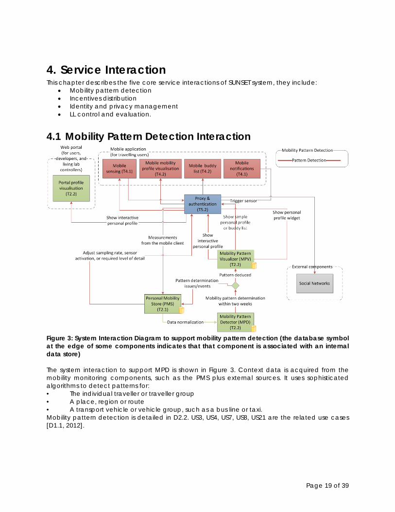
4. Service Interaction This chapter describes the five core service interactions of SUNSET system, they include:
• Mobility pattern detection • Incentives distribution • Identity and privacy management • LL control and evaluation.
4.1 Mobility Pattern Detection Interaction
Figure 3: System Interaction Diagram to support mobility pattern detection (the database symbol at the edge of some components indicates that that component is associated with an internal data store) The system interaction to support MPD is shown in Figure 3. Context data is acquired from the mobility monitoring components, such as the PMS plus external sources. It uses sophisticated algorithms to detect patterns for: • The individual traveller or traveller group • A place, region or route • A transport vehicle or vehicle group, such as a bus line or taxi. Mobility pattern detection is detailed in D2.2. US3, US4, US7, US8, US21 are the related use cases [D1.1, 2012].
Page 20 of 39
4.2 Incentives Distribution Interaction
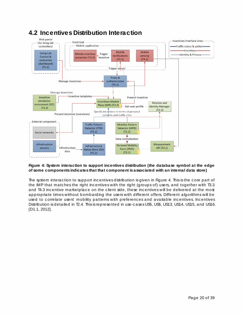
Figure 4: System interaction to support incentives distribution (the database symbol at the edge of some components indicates that that component is associated with an internal data store) The system interaction to support incentives distribution is given in Figure 4. This is the core part of the IMP that matches the right incentives with the right (groups of) users, and together with T3.3 and T4.3 incentive marketplace on the client side, these incentives will be delivered at the most appropriate times without bombarding the users with different offers. Different algorithms will be used to correlate users’ mobility patterns with preferences and available incentives. Incentives Distribution is detailed in T2.4. This is represented in use-cases US5, US6, US13, US14, US15, and US16. [D1.1, 2012].
Page 21 of 39
4.3 Identity and Privacy Interaction
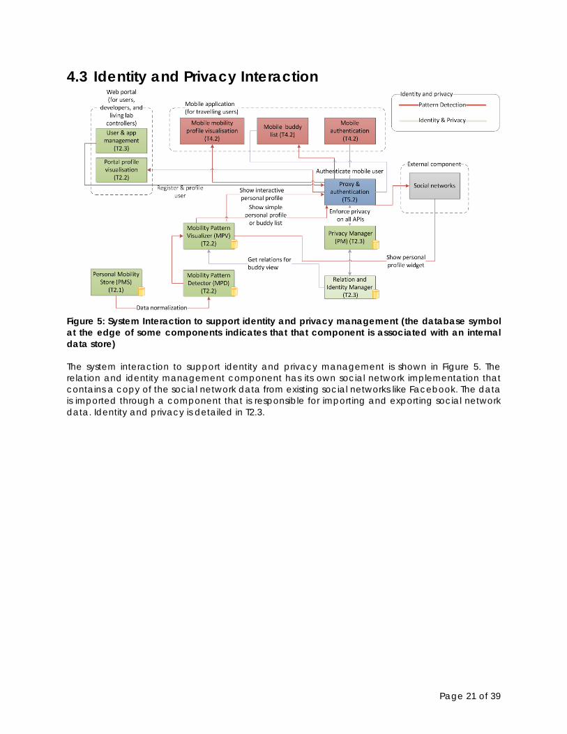
Figure 5: System Interaction to support identity and privacy management (the database symbol at the edge of some components indicates that that component is associated with an internal data store) The system interaction to support identity and privacy management is shown in Figure 5. The relation and identity management component has its own social network implementation that contains a copy of the social network data from existing social networks like Facebook. The data is imported through a component that is responsible for importing and exporting social network data. Identity and privacy is detailed in T2.3.
Page 22 of 39
4.4 LL Control & Evaluation Interaction
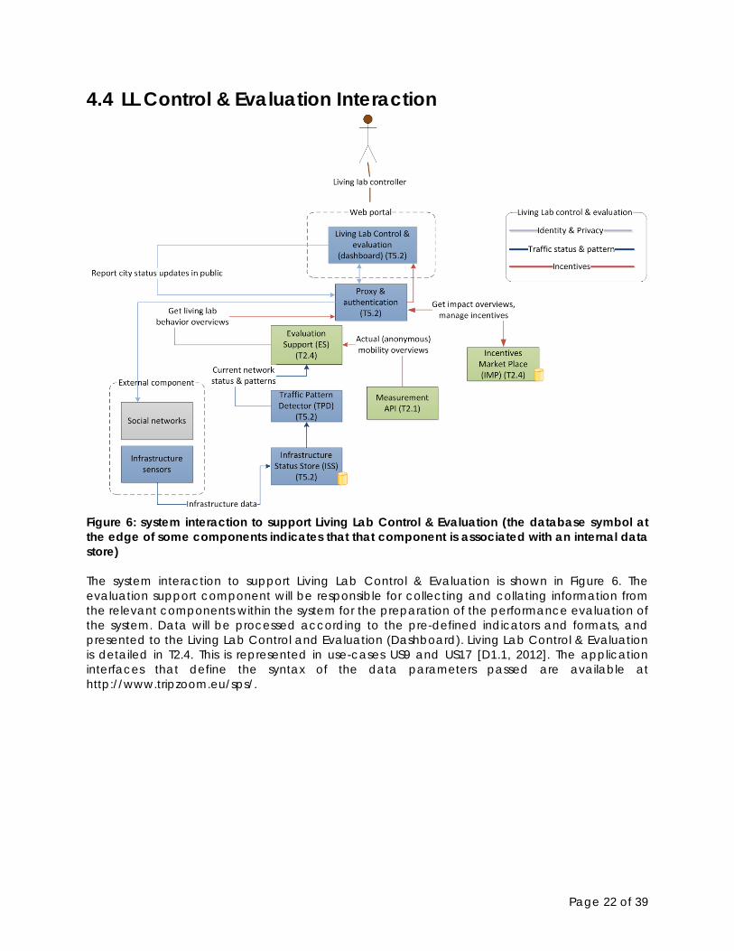
Figure 6: system interaction to support Living Lab Control & Evaluation (the database symbol at the edge of some components indicates that that component is associated with an internal data store) The system interaction to support Living Lab Control & Evaluation is shown in Figure 6. The evaluation support component will be responsible for collecting and collating information from the relevant components within the system for the preparation of the performance evaluation of the system. Data will be processed according to the pre-defined indicators and formats, and presented to the Living Lab Control and Evaluation (Dashboard). Living Lab Control & Evaluation is detailed in T2.4. This is represented in use-cases US9 and US17 [D1.1, 2012]. The application interfaces that define the syntax of the data parameters passed are available at http://www.tripzoom.eu/sps/.

Page 23 of 39
5. Deployment Overview
5.1 Deployment Issues This chapter gives an overview of the SUNSET deployment. Deploying a system based on local data in multiple cities requires us to think about the business of how to host multiple services for use in multiple city locations.
5.1.1 Supporting Multiple Cities or LLs The following requirements relate to the deployment of the SUNSET system:
• The SUNSET system must support two or three different living labs [D7.1, 2013]. It is expected to have living labs in Enschede and Gothenburg, and maybe Leeds as well.
• Each living lab requires specific functionality from the SUNSET system. For example, not all functionality of the SUNSET system may be tested in all living labs. All components share a common, living lab independent, data model, so that every component can be used in every living lab, given that the required data for the components to operate, is available.
• Each living lab may offer ‘local’ data sources, such as traffic density information coming from the sensors in the road network, information about available parking spaces, and so on. This data, which may need to be converted to a SUNSET-defined format, needs to flow into the platform so that the SUNSET components can use it. This way, the SUNSET components are independent of the actual, living lab-specific, data formats being used.
• The SUNSET system must be deployed in such a way such that the operation of each living lab is not negatively influenced by the operation of the other living labs.
• The living labs may run (partly) in parallel. • New functionality must be added to an already deployed platform in a controlled
manner, such that it does not negatively influence the regular living lab(s) operation.
5.1.2 Hosting The exact form of hosting needs to be decided. Several options are available, including, but not limited to:
• One of the SUNSET partners physically hosting multiple machines in their own data centre • Using virtualisation technology to deploy one or more ‘machines’ on the same high-
performance hardware (e.g. by using VMWare), to be placed in a data centre somewhere
• Running the platform entirely in the cloud (e.g. Amazon Elastic Compute Cloud). For performance reasons, it is recommended to co-locate all the servers in the same data centre, connected to each other via a high-speed wired LAN so that latency in the data exchange between components is minimal. If needed for the operation of the living lab, redundant hardware and software may be installed. Regardless of the solution that is chosen, procedures have to be defined for database backup and technical support in case there is a hardware failure. All developers will gain access to the staging and production environments via remote access (e.g. UltraVNC or NetSupport).
Page 24 of 39
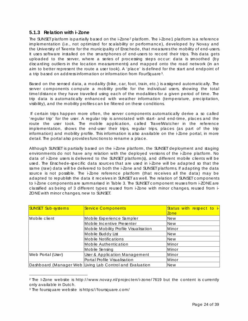
5.1.3 Relation with i-Zone The SUNSET platform is partially based on the i-Zone2 platform. The i-Zone1 platform is a reference implementation (i.e., not optimized for scalability or performance), developed by Novay and the University of Twente for the municipality of Enschede, that measures the mobility of end-users. It uses software installed on the smartphones of end-users to record their trips. This data gets uploaded to the server, where a series of processing steps occur: data is smoothed (by discarding outliers in the location measurements) and mapped onto the road network (in an aim to better represent the route a user took). A ‘place’ is defined for the start and endpoint of a trip based on address information or information from FourSquare3
.
Based on the sensed data, a modality (bike, car, foot, train, etc.) is assigned automatically. The server components compute a mobility profile for the individual users, showing the total time/distance they have travelled using each of the modalities for a given period of time. The trip data is automatically enhanced with weather information (temperature, precipitation, visibility), and the mobility profiles can be filtered on these conditions. If certain trips happen more often, the server components automatically derive a so called ‘regular trip’ for the user. A regular trip is annotated with start- and end-time, places and the route the user took. The mobile application, called TravelWatcher in the reference implementation, shows the end-user their trips, regular trips, places (as part of the trip information) and mobility profile. This information is also available on the i-Zone portal, in more detail. The portal also provides functions to rename a place. Although SUNSET is partially based on the i-Zone platform, the SUNSET deployment and staging environments do not have any relation with the deployed versions of the i-Zone platform. No data of i-Zone users is delivered to the SUNSET platform(s), and different mobile clients will be used. The Enschede-specific data sources that are used in i-Zone will be adapted so that the same (raw) data will be delivered to both the i-Zone and SUNSET platforms. If adapting the data source is not possible. The i-Zone reference platform (that receives all the data) may be adapted to republish the data it receives in SUNSET as well. The relation of SUNSET components to I-Zone components are summarised in Table 3. The SUNSET component reuses from i-ZONE are classified as being of 3 different types: reused from i-Zone with minor changes, reused from i-ZONE with minor changes, new to SUNSET.
2 The I-Zone website is http://www.novay.nl/projecten/i-zone/7619 but the content is currently only available in Dutch. 3 The foursquare website is https://foursquare.com/
SUNSET Sub-systems Service Components Status with respect to i-Zone
Mobile client Mobile Experience Sampler New Mobile Incentive Presenter New Mobile Mobility Profile Visualisation Minor Mobile Buddy List New Mobile Notifications New Mobile Authentication Minor Mobile Sensing Minor
Web Portal (User) User & Application Management Minor Portal Profile Visualisation Minor
Dashboard (Manager Web Living Lab Control and Evaluation New
Page 25 of 39
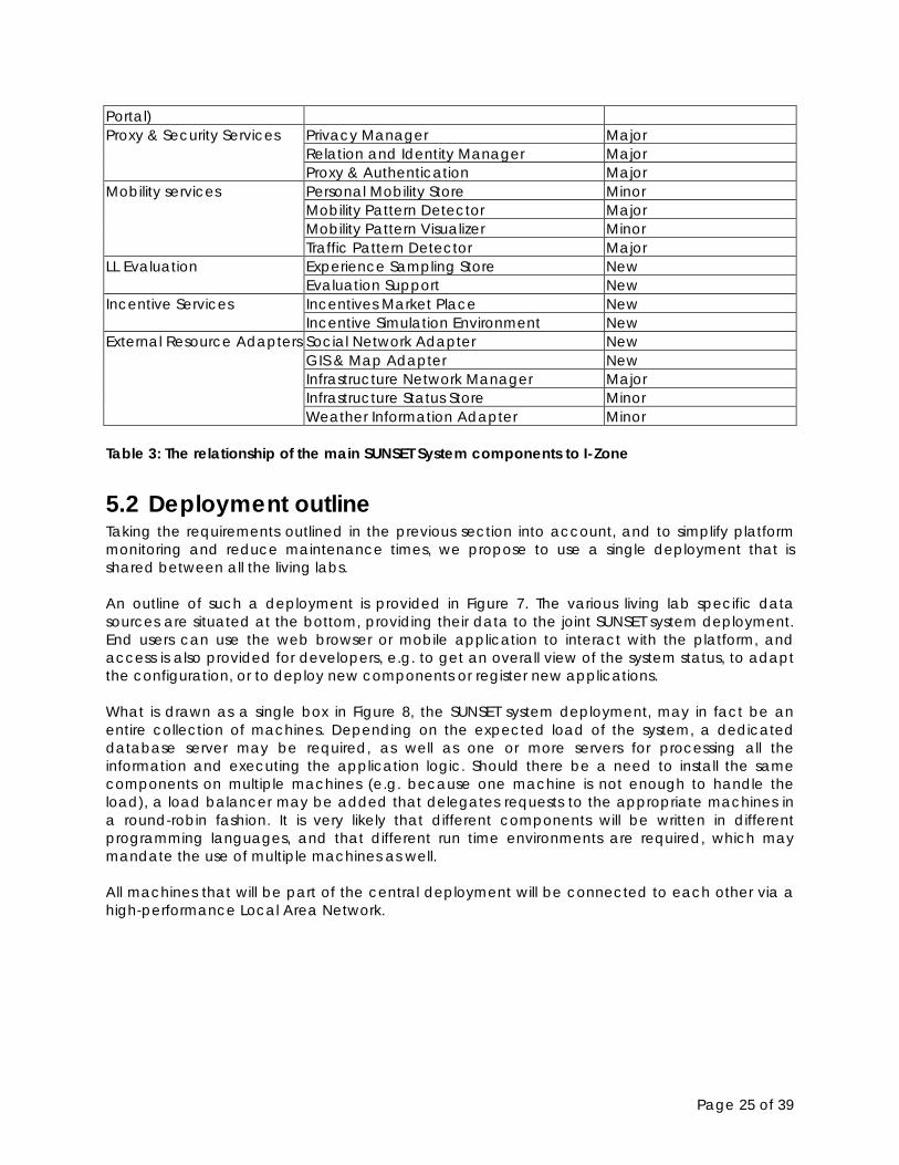
Table 3: The relationship of the main SUNSET System components to I-Zone
5.2 Deployment outline Taking the requirements outlined in the previous section into account, and to simplify platform monitoring and reduce maintenance times, we propose to use a single deployment that is shared between all the living labs. An outline of such a deployment is provided in Figure 7. The various living lab specific data sources are situated at the bottom, providing their data to the joint SUNSET system deployment. End users can use the web browser or mobile application to interact with the platform, and access is also provided for developers, e.g. to get an overall view of the system status, to adapt the configuration, or to deploy new components or register new applications. What is drawn as a single box in Figure 8, the SUNSET system deployment, may in fact be an entire collection of machines. Depending on the expected load of the system, a dedicated database server may be required, as well as one or more servers for processing all the information and executing the application logic. Should there be a need to install the same components on multiple machines (e.g. because one machine is not enough to handle the load), a load balancer may be added that delegates requests to the appropriate machines in a round-robin fashion. It is very likely that different components will be written in different programming languages, and that different run time environments are required, which may mandate the use of multiple machines as well. All machines that will be part of the central deployment will be connected to each other via a high-performance Local Area Network.
Portal) Proxy & Security Services Privacy Manager Major
Relation and Identity Manager Major Proxy & Authentication Major
Mobility services Personal Mobility Store Minor Mobility Pattern Detector Major Mobility Pattern Visualizer Minor Traffic Pattern Detector Major
LL Evaluation Experience Sampling Store New Evaluation Support New
Incentive Services Incentives Market Place New Incentive Simulation Environment New
External Resource Adapters Social Network Adapter New GIS & Map Adapter New Infrastructure Network Manager Major Infrastructure Status Store Minor Weather Information Adapter Minor

Page 26 of 39
Figure 7: SUNSET deployment outline A more detailed view of the central SUNSET deployment is given in Figure 8.
Figure 8: SUNSET deployment
Note that the actual number of machines required is highly dependent on the characteristics (in terms of processor and memory use) of all the components used and on the number of concurrent users.
5.3 Deployment process and staging Once the first living lab starts its operation, it is important that the core functionality of the platform remains stable and available around the clock. Downtime for installing new

Page 27 of 39
components should be minimal. It may therefore be required that new components can be tested on a separate, but roughly identical, environment, prior to being moved into the production environment. This so-called staging environment uses the same setup as the production platform, and will also need to be fed with information from the living lab specific data sources. The staging platform should for example allow a developer to test additions to server components or to try out new services of mobile applications, without communicating with the actual deployment environment. The staging environment does not need to be as scalable as the production platform, since its user group will solely consist of SUNSET developers and dedicated test persons. In addition to the staging platform, developers may run parts of the SUNSET platform locally for development purposes. These local installations do not receive information from the roadside sensors or information from additional living lab specific data sources by default; mock data may be used for testing purposes.
Page 28 of 39
6. Conclusions This deliverable specifies the SUNSET system’s components. These are defined in the online documentation that SUNSET uses to maintain component requirements (available from http:// http://www.tripzoom.eu/sps/). A component-based design and implementation supports two key properties for the system: high cohesion within components such that they perform well-defined functions and loose coupling between components that minimise undesired side-effects. A high cohesion within components can be achieved by using a three-tier model consisting of a fat-clients (front-end), middleware, proxies and servers (back-end). The overall SUNSET system is partitioned into the following sub-systems:
• Front end: Mobile Client; Web Portal (User); Dashboard (Manager Web Portal); • Middleware: Proxy & Security Services; • Back-end: Mobility services, LL Evaluation Support; Incentive Services; External Resource
Adapters. Support for loose-coupling among SUNSET system components can be achieved by using a hybrid distributed system interaction style. Loose-coupling will be specifically supported by leveraging the use of Representation State Transfer (REST) Models, Shared Data Repository (SDR) and Event-Driven Architectures (EDA) for different parts of the system. In SUNSET system, four types of exemplar service interaction are identified, these are: mobility pattern detection; incentive distribution; identity and privacy management and LL control and evaluation. This service design presented in this deliverable is a flexible and efficient framework that has been designed to supports the different user scenarios as defined in [D1.1, 2012]. In order to understand and foresee the technical challenges at a high level, a deployment overview is presented in terms of support of multiple cities/LLs, hosting and the relation of SUNSET to i-Zone. Finally, a single deployment plan that is shared between all the living labs is proposed in a bid to simplify platform monitoring and to reduce maintenance efforts.
Page 29 of 39
7. References [1]. [D1.1, 2012] Sunset Deliverable D1.1 Preliminary scenarios and user and system
requirements. Public document available in March 2012 via the SUNSET project Web-site http://www.sunset-project.eu/
[2]. [D7.1, 2013] Sunset Deliverable D7.1 Living lab plan. Public document available in March 2013 via the SUNSET project Web-site http://www.sunset-project.eu/
[3]. [Garlan, D. and Shaw, 1993] Garlan, D. and Shaw, M. An introduction to software architecture. In V. Ambriola and G. Tortora (eds) Advances in Software Engineering and Knowledge Engineering, Vol. 2. New York: World Scientific Publishing Company, pp. 1–39, 1993.
[4]. [Poslad, 2009] Poslad, S. Ubiquitous Computing: Smart Devices, Environments and Interactions. Wiley, ISBN: 978-0-470-03560-3, 2009.
Page 30 of 39
Appendix A
A.1 SUNSET Component overview This section provides an overview of the separate WP5 components used by the SUNSET system. At the time this deliverable was completed, the components presented here are still under development.
A.2 WP5 Components This section describes the components involved in the SUNSET system, using the following criteria and format: <abbreviation> <full component name> Description <Short description of the proposed functionality> Responsible task <Reference to the task in the DoW> Communicates with
<An overview components that interact with this component>
Data classes <Data classes as described in the interfaces> Requirements <List of essential requirements for the component> Internal processes <Textual description of how the input of the component is processed> Implementation issues
<List of implementation issues>
A.2.1 Infrastructure Network Manager INM Infrastructure Network Manager Description The Infrastructure Network Manager (INM) is responsible for storing and
serving infrastructure network data, and supports various operations using that data. The infrastructure network data describes the transportation networks available in the regions that are of interest to the SUNSET project (i.e., the Living Lab regions as well as the regions in which SUNSET functionality is tested). The data comprises those transportation networks that are relevant to the SUNSET users (road, rail, metro, …) and typically consists of nodes representing location, and segments representing a section of the network between two nodes. The INM does not provide information on the traffic status in the network; this is handled by the Infrastructure Status Store (see next component). The data stored by the INM is an excerpt of the OpenStreetMap (OSM) database (see http:// http://www.openstreetmap.org/). We chose OSM because it is freely available and provides detailed transportation network information. The INM operations are exposed through the Infrastructure Network API), They help other SUNSET components to lookup infrastructure network elements associated with GPS locations, lookup places
Page 31 of 39
associated with transportation hubs, etc. Additionally, the INM support mappings from GPS trips to trips expressed as infrastructure segments.
Responsible task T5.2 Communicates with
The INM offers basic functionality to other SUNSET components and does not rely on other components.
Interface(s) The INM functionality is used through the Infrastructure Network API. This API is REST-based and uses JSON as the data exchange format. The following calls are used by the Infrastructure Network API:
- Get the (static) details of a single infrastructure segment - Get the details of a list of infrastructure segments - Retrieve nearby places for a given location (i.e., places such as
stations, bus stops, parking garages, etc.) - Get the nearby infrastructure segment ID for a given location - Obtain the mapping of a given (GPS) location trace to a list of
infrastructure segments. This is used to associate personal mobility (recorded in terms of GPS locations) with (parts of) streets, railways, etc.
As need arise, the API may be extended to support other calls, such as finding the shortest path between one location and another (given one or multiple possible transport modalities).
Requirements The amount of data stored by the INM is substantial and depends on what exactly is imported from the OSM database for which areas. To get an indication: the OSM database dump for the whole of Europe has a compressed size of ~9 GByte and > 100 GByte uncompressed. Although we will not store the entire European infrastructure network, it is clear that the INM requires substantial disk storage capacity and RAM on the database server
Internal processes A one-time process deals with importing the excerpt from the OSM database into the SUNSET database. This involves filtering out relevant data (types of OSM entities, areas of interest,…). A continuous process handles incoming requests from other SUNSET components through the Infrastructure Network API. Some of these requests are simple and deal with serving parts of the underlying database. Others, such as mapping GPS trips to OSM segments, are more elaborate.
Implementation issues
None
A2.2 Infrastructure Status Store ISS Infrastructure Status Store Description The Infrastructure Status Store (ISS) component stores historical and
current information about the status of the infrastructure network. The ISS can be used to query the condition of the road network or other transportation networks (i.e., it provides information about traffic flow, traffic times, accidents, etc.). The traffic status is stored in reference to the nodes and segments
Page 32 of 39
available in the INM. The ISS operates in conjunction with the Traffic Pattern Detector (see next component). Together, these two components provide a single interface: the Traffic API.
Responsible task T5.2 Communicates with
Various other SUNSET components use the ISS to obtain information on the historical or current status of the traffic networks. These components are required to access the ISS through the Traffic API. The ISS itself communicates with one or more external resources (the Infrastructure Sensors) that provide measurements on the status of the transport network. These sensors typically collect status information from within the traffic network (i.e., road-side sensors, camera’s, etc.). Furthermore, the ISS may use the information gathered on the mobile clients to register the state (such as traffic flow and travel times) in the network. Finally, the ISS uses the Infrastructure Network API as a reference.
Interface(s) The ISS functionality is available to other components through the Traffic API. This API is REST-based and uses JSON as data exchange format. The following calls are expected to be available:
- Get the traffic flow and travel time on specific infrastructure segments (e.g. parts of roads), for the current situation, as well as for historical situations.
- Obtain the travel time for a complete route, for the current situation as well as for historical situations.
- Get the traffic flow and travel times for all infrastructure segments within an areas (or bounding box), for the current situation as well as for historical situations.
Other calls will be added as need arises.
Requirements The ISS depends highly on the quality and timeliness of the data from the infrastructure sensors (and mobile devices, if used). If, for instance, the sensor data is stale, the traffic status supplied by the ISS may not be suitable for many SUNSET scenarios. Another aspect is the granularity of the traffic information. Infrastructure sensors are mostly installed on main roads: if the SUNSET scenarios require very detailed information (i.e., traffic status information on minor roads), it may not be possible to support that based on the available sensor data. The amount of data coming from the sensors may be substantial: the system must be capable of supplying enough storage to store the historical status information.
Internal processes The ISS has two process running continuously and parallel. A collection process is responsible for receiving, formatting, aggregating and storing the incoming status information from the sensors. Another process is responsible for handling incoming requests from other
Page 33 of 39
components. Implementation issues
The traffic status is stored with refer to the infrastructure segments in the INM, which are OSM elements. In many cases, the sensor data information is expressed in terms of another infrastructure network. It is a challenge to translate such incoming data in terms of OSM entities.
A2.3 Traffic Pattern Detector TPD Traffic Pattern Detector Description The Traffic Pattern Detector (TPD) component models the existing
traffic status information (in the ISS) to make predictions about the status of the transportation networks in the future (i.e., taking into account the current status and historical patterns).
Responsible task T5.2 Communicates with
This component depends strongly on the ISS and has most interaction with the ISS. Furthermore, other components depend on the functionality offered by the TPD.
Interface(s) The TPD functionality is available to other components through the Traffic API. This API is REST-based and uses JSON as data exchange format. The following calls are expected to be available:
- Get the expected traffic flow and expected travel time on specific infrastructure segments (e.g. parts of roads), for a future situation.
- Obtain the expected travel time for a complete route, for a future situation.
- Get the expected traffic flow and expected travel times for all infrastructure segments within an areas (or bounding box), for a future situation.
Requirements The TPD depends on the quality, timeliness of the current status and
amount of historical data stored by the ISS. Internal processes The TPD runs a continuous process to serve incoming request from
other components. Additionally, the TPD runs batch jobs to update models for prediction and to recalculate and store intermediate (statistical) results (such as long-time averages on traffic flow and travel times for infrastructure segments).
Implementation issues
Traffic modelling and prediction is a domain in itself, which is not the main topic of research for SUNSET. It is therefore important to choose existing mechanisms and technology to implement the functionality of this component.
A2.4 Proxy & Authentication PA Proxy & Authentication Description The proxy component is responsible for securing that only registered
and authenticated users can access the data stored in the system. This is especially important as mobile and third party application will access the system on behalf of their users. Therefore, an

Page 34 of 39
authentication mechanism is employed that ensures that applications can only access data for which the user has explicitly given his/her consent.
Responsible task T5.2 in cooperation with T2.3 Communicates with
RIM, Portal
Interface(s) The PA provides the functionality for applications (such as the SUNSET mobile apps) to be registered and managed together with the consents that users have given to those. The following calls are expected to be available:
- Application management: add, get, count, update, delete - Consent management: add, get, count, update, delete - Authentication: request and authenticate tokens, validate
credentials.
Requirements As the central authentication point, the proxy component ensures that the sunset portal, its mobile applications, as well as other 3rd party component can be integrated in the system. In order to ensure that such applications and components can only request user data for which the user has explicitly given his/her consent, a handshake mechanism for authenticating, giving consents, and checking consents must be implemented. A central requirement is that the user should not need to give his/her credentials (username and password) to external resources but has a mechanism to allow these components to access particular data on his or her behalf. In combination with the Privacy Manager (PM), this authorization must also allow users to share their private resources (e.g. photos, videos, contact lists) handled by the SUNSET system in a safe and secure way.
Internal processes An Apache OAuth proxy module handles incoming requests and directly communicates with the database containing the user, application, and token information.
Implementation issues
100% security is always impossible to reach but we will use up to date technology and encryption mechanisms
A2.5 Living Lab Controls & Evaluation (Dashboard) LLC Living Lab Controls & Evaluation (Dashboard) Description This component integrates all evaluation information from other
components to facilitate live lab monitoring and widget and incentive market administration of SUNSET platform.
Responsible task T 5.2 Communicates with
The LLC communicates with • ES by monitoring the user’s input for evaluation purposes • ESS to test context conditions to poll for questions • IMP to manage incentives and widgets • MPD to visualize the mobility pattern.
Interface(s) The following interfaces are used to request different mobility
Page 35 of 39
information 1. Get and manage the incentive information 2. Get and manage all users’ trip information 3. Get and manage traffic information 4. Get and manage all users’ location information.
Requirements LLC.1.The dashboard should display both live and historical traffic information. LLC.2.The dashboard should display predicted traffic in near future. LLC.3.The dashboard should display mobility profile information of segments of the network. LLC.4. The dashboard should display each online user’s location. LLC.5. User experience answers should be visualized. LLC.6. Incentives should be visualized and manageable LLC.7. Online users should be grouped and visualized on a map in terms of mode of transport.
Internal processes The raw traffic data, user experience data and mobility pattern will be further transformed for visualisation.
Implementation issues
A2.6 Web Portal (User) WP Web Portal (User) Description This component allows developers to register external resource and
applications together with a specification of the required access patterns and individual users to grant and revoke registered external resources and applications certain access rights. It also presents user preferences and settings to users and allows extending and modifying corresponding entries.
Responsible task T 5.2 and T2.3 Communicates with
The UWP communicates with • ES by monitoring the user’s input for evaluation purposes • MPV for visualisation pattern visualisation
Interface(s) The following interfaces are expected to be available for requesting different mobility information
1. Get the incentive information 2. Get an individual user’s trip information 3. Get an individual user’s location information.
Requirements WP.1. User experience answers should be visualized. WP.2. Show user mobility patterns and visualize WP.3. Display user current and historical incentives
Internal processes The raw traffic data, user experience data and mobility pattern will be further transformed for visualisation.
Implementation issues

Page 36 of 39
A.3 System Requirements for WP5 Components This section specifies the WP5 specific component requirements listed in Section A.2. All requirements are presented in the template explained below, which links system requirements to the WP1 use cases defined in [D1.1, 2012] in the user scenario (USx) and the stakeholder scenario (SSx), to provide the rationale behind the requirement, and finally, to prioritize them which will in turn guide the development of the entire SUNSET system. T5.x <short name> Expert <Name> (<Partner>),.. Component {Mobile monitoring application, ..} Type {System, Technical4Number
} Description Source Rationale Priority
Comp.n <describes the content of the requirement>
<where does this requirement come from>
<arguments that explain why this requirement is implied by the source>
{High, Medium, Low}
Comp.n+1 Comp.n+2 Remarks <additional comments> The requirements are grouped per server-side component in the SUNSET system.
A.3.1Infrastructure Network Management T5.2 INM Expert Arjan Peddemors (NOVAY) Component Infrastructure Network Management Type System Number Description Source Rationale Priority INM.1 Retrieve the definition of
infrastructure segments (parts of roads, railways, etc.) incl. the (GPS) location of endpoints
US3-US12, US14-US16, US18-US22, SS1, SS2, SS4
Used for a broad range of services, for instance to display an infrastructure segment on a map
High
INM.2 Get places close to a (GPS) location
US3-US12, US14-US16, US18-US22
Helps to find places where users reside
Medium
INM.3 Retrieve the infrastructure segments close to a (GPS) location
US3-US12, US14-US16, US18-US22
Allows to find the position of a user in the infrastructure network
Medium
INM.4 Get the mapping of a given (GPS) location trace to a list of infrastructure segments.
US3-US12, US14-US16, US19-US22
Allows for the expression of mobility traces in terms of routes through the infrastructure network
High
Remarks
A.3.2 Infrastructure Status Store T5.2 ISS
4 Some system requirements relate directly to user requirements. Other system requirements that are not directly linked to user requirements are called technical requirements.
Page 37 of 39
Expert Component Infrastructure Status Store Type System Number Description Source Rationale Priority ISS.1 ISS should be able to
represent traffic incidents SS1 There should be a way to
measure the effect of the SUNSET system to the reduction of traffic congestion.
High
ISS.2 ISS should be able to map traffic incidents to routes
US7, US11 Mapping traffic incidents to the road network is needed to determine if a user’s route is obstructed by a jam or other incident.
High
ISS.3 ISS should be able to map POIs (e.g., regarding incentives offers or road cameras) to the network
US11 Mapping POIs to the network is needed to relate location-based services to users
High
Remarks
A3.3 Traffic Pattern Detector T5.2 TPD Expert Koen Jacobs (LOCNET), Sebastiaan Raaphorst (LOCNET) Component Traffic Pattern Detector Type System Number Description Source Rationale Priority TPD.1 TPD should be able to map
sensor data to OSM network segments
N/A In order to calculate travel times, the sensor data should be represented in the format of the road network.
High
TPD.2 TPD should be able to perform travel time predictions based on historical information
N/A Prediction based on statistical analysis of historic sensor data could yield a travel time prediction for given moment in the future.
High
Remarks
A3.4 Proxy & Authentication T5.2 PA Expert Paul Holleis, Marko Luther, DOCOMO Component Proxy & Authentication Type System Number Description Source Rationale Priority PA.1 Users must be able to allow
applications access to SUNSET components and (partial( data without giving away their credentials
DoW, Workpackage overview WP2
SUNSET and 3rd party apps are central for SUNSET users. However, they should only need to provide their credentials in one central place and have restricted access only to the data they need and are
High
Page 38 of 39
granted access too. PA.2 Means to identify and
authenticate users PA.1 Only authenticated users
should be allowed to access data
High
PA.3 Token handling including creation, signing, exchange, and revocation.
PA.1 Tokens are central in storing authentication data
PA.4 Consent handling PA.1 Consents are central in describing to the system and to the user what components is allowed to access which data
High
PA.5 Endpoint for all internal subcomponents of the SUNSET system that, after token verification forwards messages extended by information indicating the authorized entity and the given consents
US.2 Components need an interface through which they can access required data. This interface should check the validity of the request and adorn it with additional information such that components can further decide whether the correct consent has been approved by the user.
High
Remarks
A3.5 Living Lab Controls & Evaluation (Dashboard) T5.2 LLC Expert Zhenchen Wang (QMUL) Component Living Lab Controls & Evaluation Type System Number Description Source Rationale Priority LLC.1 Historical and live traffic
information display SS1, SS6 These information is
processed on the central server which can effectively reduce the duplication
High
LLC.2 Traffic prediction display SS1, SS6, SS4
To support policy maker decision making
Medium
LLC.3 Mobility profile display SS1, SS4 To support policy maker decision making
High
LLC.4 Online user location display SS1, SS4 To support mobility visualisation
Medium
LLC.5 User experience answers display
SS5 To support policy maker decision making and Living lab control
High
LLC.6 Incentive management SS3 To support incentive updates
High
LLC.7 Group users in terms of mode of transport
SS2 To support policy maker decision making
High
Remarks

Page 39 of 39
A3.6 Web Portal (User) T5.2 WP Expert Thomas Oshin (QMUL) Component User Web Portal Type System Number Description Source Rationale Priority WP.1 User experience answers
are visualized SS5 To support policy maker
decision making and Living lab controller
High
WP.2 Show user mobility patterns and visualize
SS1, SS4 To support mobility visualisation
High
WP.3 Display user current and historical incentives
SS3 To support incentive update
High
Remarks


![The Solar System’s Motion in the Galactic Tidal Field 597[3].pdfThe Solar System’s Motion in the Galactic Tidal Field ... parameters for the solar system’s motion were taken](https://img.pdfslide.net/doc/110x75/5ab63e5c7f8b9a1a048d9cc1/the-solar-systems-motion-in-the-galactic-tidal-field-5973pdfthe-solar-systems.jpg)