Embed Size (px)
Citation preview

1 Description
Temperature transducers for thermocouples
MINI MCR-2-TC-UI(-PT)(-C)
© PHOENIX CONTACT
Data sheet
Configurable 3-way isolated temperature transducer with
pluggable connection technology. The device is suitable for
the connection of thermocouples.
The measured values are converted into a linear and freely
configurable current or voltage signal.
Features
– Configurable, 3-way isolated temperature transducer
with plug-in connection technology.
– 15 default thermocouple types
– Additional types can be set by means of user
characteristic curves
– Approval for Ex-zone 2 (nA)
– Screw or push-in connection available
– Can be supplied configured or unconfigured
– Reinforced insulation according to IEC 61010-1
– Supply voltage range 9.6 ... 30 V DC
WARNING: Correct usage in potentially explosive areas
The module is a category 3 item of electrical equipment. It is absolutely vital to follow the instructions provided
here during installation and observe the information in the "Safety regulations and installation notes".
This device offers the option of NFC communication.
You can use the MINI Analog Pro Smartphone app via the NFC interface of your Smartphone to configure the
device and to call-up DIP switch setting help and comprehensive module information.
The MINI Analog Pro Smartphone app is available to you free.
Make sure you always use the latest documentation.
It can be downloaded from the product at phoenixcontact.net/products.
This document is valid for the products listed in the “Ordering data”.
106016_en_03 2017-01-25

MINI MCR-2-TC-UI(-PT)(-C)
106016_en_03 PHOENIX CONTACT 2 / 19
2 Table of contents
1 Description .............................................................................................................................. 1
2 Table of contents ..................................................................................................................... 2
3 Ordering data .......................................................................................................................... 3
4 Technical data ......................................................................................................................... 6
5 Safety regulations and installation notes.................................................................................. 9
5.1 Installation notes ................................................................................................................. 9
5.2 Installation in Zone 2............................................................................................................. 9
5.3 UL Notes ........................................................................................................................... 9
6 Installation ............................................................................................................................. 10
6.1 Connection notes .............................................................................................................. 10
6.2 Structure ......................................................................................................................... 10
6.3 Block diagram................................................................................................................... 10
6.4 Power supply.................................................................................................................... 10
6.5 Assembly......................................................................................................................... 11
6.6 FASTCON Pro plugs .......................................................................................................... 11
6.7 Fault monitoring FM ........................................................................................................... 12
6.8 Current measurement ......................................................................................................... 12
6.9 Marking........................................................................................................................... 12
7 Configuration ......................................................................................................................... 13
7.1 Configuration via DIP switches.............................................................................................. 13
7.2 Configuration via software.................................................................................................... 16
7.3 Configuration via MINI Analog Pro app.................................................................................... 16
8 Function description .............................................................................................................. 17
8.1 Notes on using thermocouples.............................................................................................. 17
8.2 Analog switching output ...................................................................................................... 18
8.3 Monitoring........................................................................................................................ 18
8.4 Limiting behavior of the analog output ..................................................................................... 18
8.5 Diagnostic functions and error messages ................................................................................ 18
8.6 Simulation mode/force ....................................................................................................... 18
9 Diagnostics and status indicators .......................................................................................... 19

MINI MCR-2-TC-UI(-PT)(-C)
106016_en_03 PHOENIX CONTACT 3 / 19
Description Type Order No. Pcs./Pkt.
Configurable temperature transducer with plug-in
connection technology for connecting thermocouples.
Configurable via DIP switch or software. Screw
connection technology, standard configuration
MINI MCR-2-TC-UI 2902055 1
Configurable temperature transducer with plug-in
connection technology for connecting thermocouples.
Configurable via DIP switch or software. Push-in
connection technology, standard configuration
MINI MCR-2-TC-UI-PT 2905249 1
Configurable temperature transducer with plug-in
connection technology for connecting thermocouples.
Configurable via DIP switch or software. Screw
connection technology, order configuration
MINI MCR-2-TC-UI-C 2902053 1
Configurable temperature transducer with plug-in
connection technology for connecting thermocouples.
Configurable via DIP switch or software. Push-in
connection technology, order configuration
MINI MCR-2-TC-UI-PT-C 2905248 1
3 Ordering data
Accessories Type Order No. Pcs./Pkt.
Programming adapter with USB interface, for
programming with software. The USB driver is included in
the software solutions for the products to be programmed,
such as measuring transducers or motor managers.
IFS-USB-PROG-ADAPTER 2811271 1
DIN rail connector for DIN rail mounting. Universal for
TBUS housing. Gold-plated contacts, 5-pos. Plug
component, Number of positions: 5, Pitch: 3.81 mm
ME 6,2 TBUS-2 1,5/5-ST-3,81
GN
2869728 10
Power terminal with plug-in connection technology for
delivering the supply voltage to the DIN rail connector.
Monitoring of the supply voltages in combination with the
fault monitoring module. Screw connection technology
MINI MCR-2-PTB 2902066 1
Power terminal with plug-in connection technology for
delivering the supply voltage to the DIN rail connector.
Monitoring of the supply voltages in combination with the
fault monitoring module. Push-in connection technology
MINI MCR-2-PTB-PT 2902067 1
Fault monitoring module with plug-in connection
technology for evaluating and reporting group errors from
the FM system and for monitoring the supply voltages.
Error reporting via N/O contact. Screw connection
technology, standard configuration
MINI MCR-2-FM-RC 2904504 1
Fault monitoring module with plug-in connection
technology for evaluating and reporting group errors from
the FM system and for monitoring the supply voltages.
Error reporting via N/O contact. Push-in connection
technology, standard configuration
MINI MCR-2-FM-RC-PT 2904508 1
Primary-switched MINI POWER supply for DIN rail
mounting, input: 1-phase, output: 24 V DC/1.5 A
MINI-SYS-PS-100-240AC/
24DC/1.5
2866983 1
MINI MCR-2-TC-UI(-PT)(-C)
106016_en_03 PHOENIX CONTACT 4 / 19
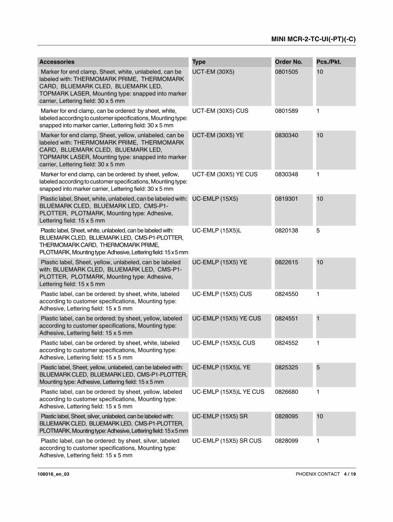
Marker for end clamp, Sheet, white, unlabeled, can be
labeled with: THERMOMARK PRIME, THERMOMARK
CARD, BLUEMARK CLED, BLUEMARK LED,
TOPMARK LASER, Mounting type: snapped into marker
carrier, Lettering field: 30 x 5 mm
UCT-EM (30X5) 0801505 10
Marker for end clamp, can be ordered: by sheet, white,
labeled according to customer specifications, Mounting type:
snapped into marker carrier, Lettering field: 30 x 5 mm
UCT-EM (30X5) CUS 0801589 1
Marker for end clamp, Sheet, yellow, unlabeled, can be
labeled with: THERMOMARK PRIME, THERMOMARK
CARD, BLUEMARK CLED, BLUEMARK LED,
TOPMARK LASER, Mounting type: snapped into marker
carrier, Lettering field: 30 x 5 mm
UCT-EM (30X5) YE 0830340 10
Marker for end clamp, can be ordered: by sheet, yellow,
labeled according to customer specifications, Mounting type:
snapped into marker carrier, Lettering field: 30 x 5 mm
UCT-EM (30X5) YE CUS 0830348 1
Plastic label, Sheet, white, unlabeled, can be labeled with:
BLUEMARK CLED, BLUEMARK LED, CMS-P1-
PLOTTER, PLOTMARK, Mounting type: Adhesive,
Lettering field: 15 x 5 mm
UC-EMLP (15X5) 0819301 10
Plastic label, Sheet, white, unlabeled, can be labeled with:
BLUEMARK CLED, BLUEMARK LED, CMS-P1-PLOTTER,
THERMOMARK CARD, THERMOMARK PRIME,
PLOTMARK, Mounting type: Adhesive, Lettering field: 15 x 5 mm
UC-EMLP (15X5)L 0820138 5
Plastic label, Sheet, yellow, unlabeled, can be labeled
with: BLUEMARK CLED, BLUEMARK LED, CMS-P1-
PLOTTER, PLOTMARK, Mounting type: Adhesive,
Lettering field: 15 x 5 mm
UC-EMLP (15X5) YE 0822615 10
Plastic label, can be ordered: by sheet, white, labeled
according to customer specifications, Mounting type:
Adhesive, Lettering field: 15 x 5 mm
UC-EMLP (15X5) CUS 0824550 1
Plastic label, can be ordered: by sheet, yellow, labeled
according to customer specifications, Mounting type:
Adhesive, Lettering field: 15 x 5 mm
UC-EMLP (15X5) YE CUS 0824551 1
Plastic label, can be ordered: by sheet, white, labeled
according to customer specifications, Mounting type:
Adhesive, Lettering field: 15 x 5 mm
UC-EMLP (15X5)L CUS 0824552 1
Plastic label, Sheet, yellow, unlabeled, can be labeled with:
BLUEMARK CLED, BLUEMARK LED, CMS-P1-PLOTTER,
Mounting type: Adhesive, Lettering field: 15 x 5 mm
UC-EMLP (15X5)L YE 0825325 5
Plastic label, can be ordered: by sheet, yellow, labeled
according to customer specifications, Mounting type:
Adhesive, Lettering field: 15 x 5 mm
UC-EMLP (15X5)L YE CUS 0826680 1
Plastic label, Sheet, silver, unlabeled, can be labeled with:
BLUEMARK CLED, BLUEMARK LED, CMS-P1-PLOTTER,
PLOTMARK, Mounting type: Adhesive, Lettering field: 15 x 5 mm
UC-EMLP (15X5) SR 0828095 10
Plastic label, can be ordered: by sheet, silver, labeled
according to customer specifications, Mounting type:
Adhesive, Lettering field: 15 x 5 mm
UC-EMLP (15X5) SR CUS 0828099 1
Accessories Type Order No. Pcs./Pkt.

MINI MCR-2-TC-UI(-PT)(-C)
106016_en_03 PHOENIX CONTACT 5 / 19
Plastic label, Sheet, silver, unlabeled, can be labeled with:
BLUEMARK CLED, BLUEMARK LED, CMS-P1-
PLOTTER, PLOTMARK, Mounting type: Adhesive,
Lettering field: 15 x 5 mm
UC-EMLP (15X5)L SR 0828103 5
Marker strip, Roll, white, unlabeled, can be labeled with:
THERMOMARK ROLL, THERMOMARK ROLL X1,
THERMOMARK ROLLMASTER 300/600,
THERMOMARK X1.2, THERMOMARK S1.1, Mounting
type: Adhesive, Lettering field: continuous x 5 mm
SK 5,0 WH:REEL 0805221 1
DIN rail connector (TBUS), 5-pos., for bridging the supply
voltage, can be snapped onto NS 35/... DIN rails
according to EN 60715
ME 6,2 TBUS-2 1,5/5-ST-3,81
GY
2695439 10
Bluetooth programming adapter with µUSB and S-PORT
interface for wireless programming and monitoring. The
driver is included in the software solutions for the products
to be programmed, such as measuring transducers or
motor managers.
IFS-BT-PROG-ADAPTER 2905872 1
Accessories Type Order No. Pcs./Pkt.

MINI MCR-2-TC-UI(-PT)(-C)
106016_en_03 PHOENIX CONTACT 6 / 19
4 Technical data
Input
Configurable/programmable Yes
Sensor type B, C, E, J, K, N, R, S, T, L, U, A-1, A-2, A-3, M, L
Temperature measuring range -250 °C ... 2500 °C (Range depends on sensor type, range can
be set freely via software or in increments from -150°C to
1350°C via DIP switches)
Measuring range span min. 50 K
Number of inputs 1
Output
Number of outputs 1
Voltage output signal 0 V ... 5 V (via DIP switch)
1 V ... 5 V (via DIP switch)
0 V ... 10 V (via DIP switch)
10 V ... 0 V (via DIP switch)
0 V ... 10.5 V (Can be set via software)
Max. voltage output signal approx. 12.3 V
Short-circuit current < 31.5 mA
Current output signal 0 mA ... 20 mA (via DIP switch)
4 mA ... 20 mA (via DIP switch)
20 mA ... 0 mA (via DIP switch)
20 mA ... 4 mA (via DIP switch)
0 mA ... 21 mA (Can be set via software)
Max. current output signal 24.6 mA
Non-load voltage < 17.5 V
Configurable/programmable Yes
Load/output load voltage output ≥ 10 kΩ
Ripple < 10 mVrms
Load/output load current output ≤ 600 Ω (at 20 mA)
Resolution, outputs (voltage) 1 mV
Resolution, outputs (current) 2 µA
Supply
Supply voltage range 9.6 V DC ... 30 V DC (The DIN rail bus connector (ME 6,2
TBUS-2 1,5/5-ST-3,81 GN, Order No. 2869728) can be used to
bridge the supply voltage. It can be snapped onto a 35 mm DIN
rail according to EN 60715))
Typical current consumption 32.7 mA (24 V DC)
66.8 mA (12 V DC)
Power consumption ≤ 850 mW (at IOUT = 20 mA, 9.6 V DC, 600 Ω load)
Status and diagnostics indicators
Indication Red LED
Operating voltage display Green LED
MINI MCR-2-TC-UI(-PT)(-C)
106016_en_03 PHOENIX CONTACT 7 / 19
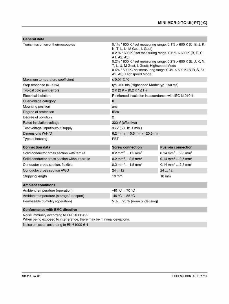
General data
Transmission error thermocouples 0.1% * 600 K / set measuring range; 0.1% > 600 K (C, E, J, K,
N, T, L, U, M Gost, L Gost)
0.2 % * 600 K / set measuring range; 0.2 % > 600 K (B, R, S,
A1, A2, A3)
0.2% * 600 K / set measuring range; 0.2% > 600 K (E, J, K, N,
T, L, U, M Gost, L Gost); Highspeed Mode
0.4% * 600 K / set measuring range; 0.4% > 600 K (B, R, S, A1,
A2, A3); Highspeed Mode
Maximum temperature coefficient ≤ 0.01 %/K
Step response (0–99%) typ. 400 ms (Highspeed Mode: typ. 150 ms)
Typical cold point errors 2 K (2 K + (0,2 K * ΔT))
Electrical isolation Reinforced insulation in accordance with IEC 61010-1
Overvoltage category II
Mounting position any
Degree of protection IP20
Degree of pollution 2
Rated insulation voltage 300 V (effective)
Test voltage, input/output/supply 3 kV (50 Hz, 1 min.)
Dimensions W/H/D 6.2 mm / 110.5 mm / 120.5 mm
Type of housing PBT
Connection data Screw connection Push-in connection
Solid conductor cross section with ferrule 0.2 mm² ... 1.5 mm² 0.14 mm² ... 2.5 mm²
Solid conductor cross section without ferrule 0.2 mm² ... 2.5 mm² 0.14 mm² ... 2.5 mm²
Conductor cross section, flexible 0.2 mm² ... 1.5 mm² 0.14 mm² ... 2.5 mm²
Conductor cross section AWG 24 ... 12 24 ... 12
Stripping length 10 mm 10 mm
Ambient conditions
Ambient temperature (operation) -40 °C ... 70 °C
Ambient temperature (storage/transport) -40 °C ... 85 °C
Permissible humidity (operation) 5 % ... 95 % (non-condensing)
Conformance with EMC directive
Noise immunity according to EN 61000-6-2
When being exposed to interference, there may be minimal deviations.
Noise emission according to EN 61000-6-4

MINI MCR-2-TC-UI(-PT)(-C)
106016_en_03 PHOENIX CONTACT 8 / 19
Conformance/Approvals
Conformance CE-compliant
ATEX II 3 G Ex nA IIC T4 Gc X
UL, USA/Canada UL 508 Listed
UL, USA/Canada Class I, Div. 2, Groups A, B, C, D T6
UL, USA/Canada Class I, Zone 2, Group IIC T6
Shipbuilding DNV GL 14445-15HH C, EMC2
MINI MCR-2-TC-UI(-PT)(-C)
106016_en_03 PHOENIX CONTACT 9 / 19
5 Safety regulations and installation notes
5.1 Installation notes
• The category 3 device is suitable for installation in potentially
explosive area zone 2. It fulfills the requirements of
EN 60079-0:2012 and EN 60079-15:2010.
• Installation, operation, and maintenance may only be
carried out by qualified electricians. Follow the installation
instructions as described. When installing and operating
the device, the applicable regulations and safety directives
(including national safety directives), as well as generally
approved technical regulations, must be observed. The
safety data is provided in this package slip and on the
certificates (conformity assessment, additional approvals
where applicable).
• While the devices are in operation, contact-dangerous
voltages may be present on the control elements. For this
reason parameterization, conductor connection, and
opening of the module lid are allowed only when devices
are in a de-energized state unless the connected circuits
are exclusively SELV or PELV circuits.
• The device must not be opened or modified. Do not
repair the device yourself, replace it with an equivalent
device. Repairs may only be carried out by the
manufacturer. The manufacturer is not liable for
damage resulting from violation.
• The IP20 protection (IEC 60529/EN 60529) of the device
is intended for use in a clean and dry environment. The
device must not be subject to mechanical strain and/or
thermal loads, which exceed the limits described.
• The device is not designed for use in atmospheres with
a danger of dust explosions.
• The device complies with the EMC regulations for
industrial areas (EMC class A). When using the device
in residential areas, it may cause radio interference.
• If the device is not used as described in the documentation,
the intended protection can be negatively affected.
• To protect the device against mechanical or electrical
damage, install it in a suitable housing with appropriate
degree of protection as per IEC 60529.
• Provide a switch/circuit breaker close to the device, which
is labeled as the disconnecting device for this device.
• Provide for a overcurrent protection device (I ≤ 4 A) in
the installation.
• There is a double isolation of 300 Veff between
neighboring modules of the same type oriented the same
way. The device has a base isolation of 150 Veff to other
neighboring modules on the side with the DIP switch.
• The voltages present at the input, output and supply are
extra-low voltages (ELV). Depending on the
application, dangerous voltage (> 30 V) against ground
could occur. For this event, safe electrical isolation from
the other connections has been implemented.
• The device must be stopped if it is damaged, has been
subjected to an impermissible load, stored incorrectly,
or if it malfunctions.
• Only use copper connecting cables providing the
permitted temperature range (60°C/75°C).
5.2 Installation in Zone 2
• Observe the specified conditions for use in potentially
explosive areas! Install the device in a suitable
approved housing (with a minimum of IP54 protection)
that meets the requirements of EN 60079-15. Observe
the requirements of EN 60079-14.
• Only devices which are designed for operation in Ex zone
2 and are suitable for the conditions at the installation
location may be connected to the circuits in the Ex zone.
• In potentially explosive areas, terminals may only be
snapped onto or off the DIN rail connector and wires
may only be connected or disconnected when the
power is switched off.
• The device must be stopped and immediately removed
from the Ex area if it is damaged, was subject to an
impermissible load, stored incorrectly or if it
malfunctions.
5.3 UL Notes
INDUSTRIAL CONTROL EQUIPMENT FOR
HAZARDOUS LOCATIONS 45FP
1 Suitable for use in class 1, division 2, groups A, B, C and
D hazardous locations, or nonhazardous locations only.
2 WARNING - EXPLOSION HAZARD: Do not disconnect
equipment unless power has been removed or the area
is known to be non-hazardous.
3 WARNING - EXPLOSION HAZARD: Substitution of any
components may impair suitability for Class I, Division 2.
4 This device is open-type and is required to be installed
in an enclosure suitable for the environment and can
only be accessed with the use of a tool or key.
MINI MCR-2-TC-UI(-PT)(-C)
106016_en_03 PHOENIX CONTACT 10 / 19
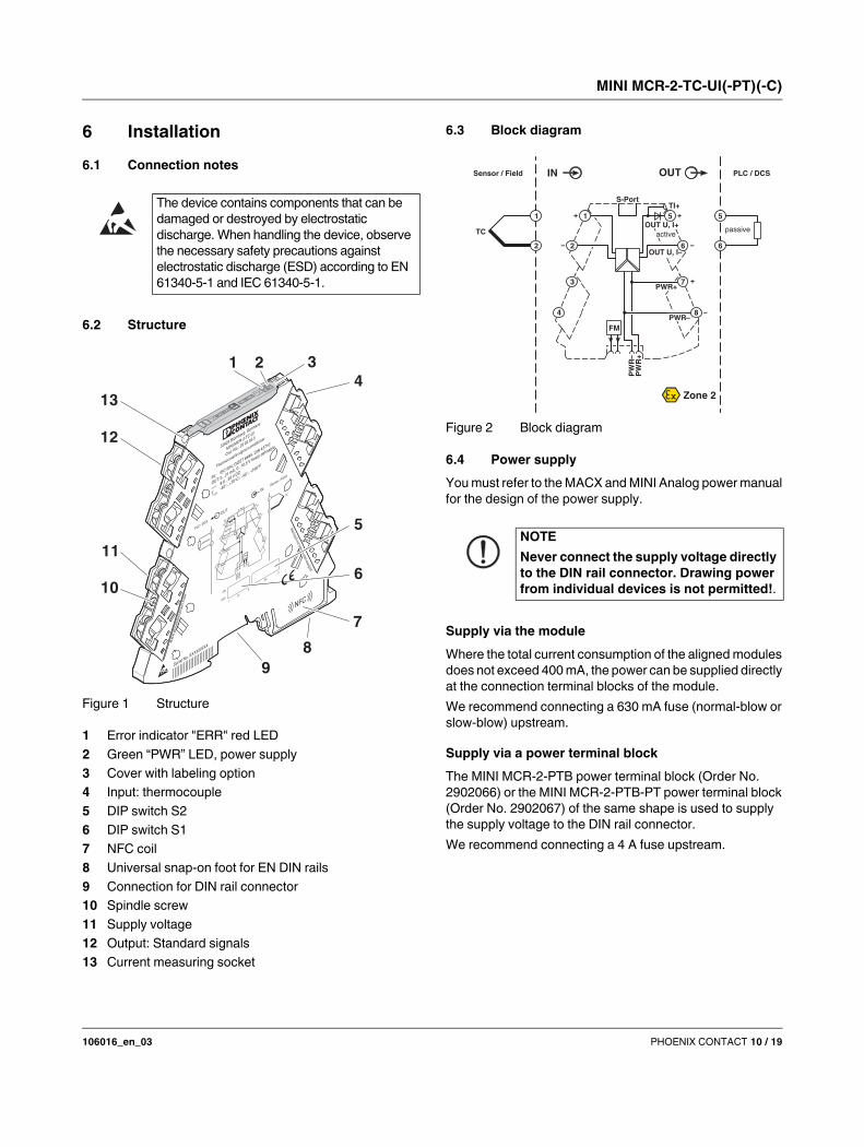
6 Installation
6.1 Connection notes
6.2 Structure
Figure 1 Structure
1 Error indicator "ERR" red LED
2 Green “PWR” LED, power supply
3 Cover with labeling option
4 Input: thermocouple
5 DIP switch S2
6 DIP switch S1
7 NFC coil
8 Universal snap-on foot for EN DIN rails
9 Connection for DIN rail connector
10 Spindle screw
11 Supply voltage
12 Output: Standard signals
13 Current measuring socket
6.3 Block diagram
Figure 2 Block diagram
6.4 Power supply
You must refer to the MACX and MINI Analog power manual
for the design of the power supply.
Supply via the module
Where the total current consumption of the aligned modules
does not exceed 400 mA, the power can be supplied directly
at the connection terminal blocks of the module.
We recommend connecting a 630 mA fuse (normal-blow or
slow-blow) upstream.
Supply via a power terminal block
The MINI MCR-2-PTB power terminal block (Order No.
2902066) or the MINI MCR-2-PTB-PT power terminal block
(Order No. 2902067) of the same shape is used to supply
the supply voltage to the DIN rail connector.
We recommend connecting a 4 A fuse upstream.
The device contains components that can be
damaged or destroyed by electrostatic
discharge. When handling the device, observe
the necessary safety precautions against
electrostatic discharge (ESD) according to EN
61340-5-1 and IEC 61340-5-1.
7
4
8
9
10
11
12
3
13
21
5
6
NOTE
Never connect the supply voltage directly
to the DIN rail connector. Drawing power
from individual devices is not permitted!.
PW
R+
PW
R–
+
+
–
–
passive
IN OUT
FM
1 5
2 6
8
5
6
Zone 2
Sensor / Field PLC / DCS
3
4
7
S-Port
OUT U, I–
OUT U, I+
PWR+
PWR–
1
2
TI+
TC
+
–
active

MINI MCR-2-TC-UI(-PT)(-C)
106016_en_03 PHOENIX CONTACT 11 / 19
Supply via a system power supply unit
The system power supply unit with 1.5 A output current
connects the DIN rail connector to the supply voltage and
can thus be used to supply several modules from the mains.
– MINI-SYS-PS-100-240AC/24DC/1.5 (Order No. 2866983)
– Potentially explosive areas:
MINI-PS-100-240AC/24DC/1.5/EX (Order No. 2866653)
6.5 Assembly
Figure 3 Mounting and removing
– Mount the module on a 35 mm DIN rail according to EN 60715.
– When using the DIN rail connector, first place it into the
DIN rail (see A – C). It is used to bridge the power
supply. It is also absolutely vital that you snap the
module and the DIN rail connector into position in the
correct direction: the snap-on foot should be at the
bottom and the connector on the left.
6.6 FASTCON Pro plugs
The device has pluggable connection terminals with an
integrated test disconnect terminal block, with either push-in
or screw-in connection technology.
You can plug or screw the FASTCON Pro plugs onto the
device directly without tools. You can use the integrated
spindle screw to easily remove the plugs from the module or
set the isolating position, even when the plugs are
connected. For this purpose, use a screwdriver of sufficient
width, e.g. SZF 1-0.6x3.5 (order number: 1204517).
4-way coding prevents incorrect insertion into the module.
Screw connection:
Figure 4 Screw connection
• Insert the wire into the corresponding connection
terminal block.
• Use a screwdriver to tighten the screw in the opening
above the connection terminal block.
Push-in connection:
Figure 5 Push-in connection
• Insert the wire into the corresponding connection
terminal block.
A
D
C
B
E
MINI MCR-2-…AWG 26-16
0,2-1,5 mm2
10 mm
A
B
0,5-0,6 Nm
5-7 lb ln
B
A
MINI MCR-2-…-PT
A
AWG 26-12
0,2-2,5 mm2
10 mm

MINI MCR-2-TC-UI(-PT)(-C)
106016_en_03 PHOENIX CONTACT 12 / 19
6.7 Fault monitoring FM
In addition to module and power supply failures, known
faults in the signal input of the module are reported via the
DIN rail connector to the form-matched MINI MCR-2-FM-RC
(order number 2904504) or MINI MCR-2-FM-RC-PT (order
number 2904508) fault monitoring module. The module
reports the error centrally via an N/C contact.
A fault monitoring module is only required once in a group.
There is no need for individual evaluation of up to 115
connected Mini Analog Pro signal conditioners.
For the behavior of the fault monitoring contact for the
different DIP switch configurations, please refer to the
corresponding table.
6.8 Current measurement
The device allows current measurement without disconnection of
the conductors by means of integrated test disconnect terminals.
Test sockets which support current measurement are
marked TI+ or TI-.
For the current measurement, use 2 mm probe tips of the
type Fluke TL75-1 or probe tips with a comparable tip shape.
Figure 6 Test disconnect terminal block
Furthermore, individual circuits can be specifically
disconnected, e.g. for commissioning.
You can set the isolating position by turning the integrated
spindle screw through 180°. The isolating position is
indicated by the marking on the plugs.
Figure 7 Disconnect position
6.9 Marking
Standard UCT-EM... or UC-EMLP tags are available for
marking the devices and can be printed as per customer
requirements. In addition, the covers provide enough space for
the use of freely chosen sticky labels such as SK 5.0 WH:REEL
without concealing the LED diagnostic indicators.

MINI MCR-2-TC-UI(-PT)(-C)
106016_en_03 PHOENIX CONTACT 13 / 19
7 Configuration
The device is supplied with the following basic settings:
Type J IEC 584 TC sensor; cold junction compensation
"ON"; -200...1200°C; output 4...20 mA; error evaluation
according to NE43 (downscale); fault monitoring contact
reacts upon any error.
Configuration is possible for all configuration variants
without supply voltage.
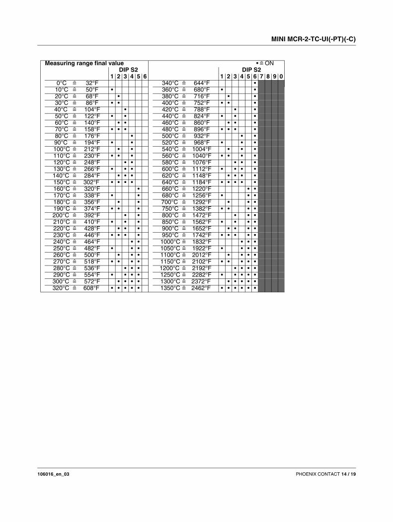
7.1 Configuration via DIP switches
At delivery, all DIP switches are in the "OFF" position.
Configure the DIP switches according to the planned
application using the configuration tables.
Configuration tables
• = ON DIP S1
1 2 3 4 5 6 7 8
Sensor type J (IEC 584)
K (IEC 584) •
Cold junction compensation OFF
ON •
Analog output signal 0...20 mA
20...0 mA •
4...20 mA •
20...4 mA • •
0...10 V •
10...0 V • •
0...5 V • •
1...5 V • • •
Start temperature 0°C 32°F
-10°C 14°F •
-20°C -4°F •
-30°C -22°F • •
-40°C -40°F •
-50°C -58°F • •
-100 °C -148°F • •
-150 °C -238°F • • •
MINI MCR-2-TC-UI(-PT)(-C)
106016_en_03 PHOENIX CONTACT 14 / 19
Measuring range final value • = ON
DIP S2 DIP S2
1 2 3 4 5 6 1 2 3 4 5 6 7 8 9 0
0°C 32°F 340°C 644°F •
10°C 50°F • 360°C 680°F • •
20°C 68°F • 380°C 716°F • •
30°C 86°F • • 400°C 752°F • • •
40°C 104°F • 420°C 788°F • •
50°C 122°F • • 440°C 824°F • • •
60°C 140°F • • 460°C 860°F • • •
70°C 158°F • • • 480°C 896°F • • • •
80°C 176°F • 500°C 932°F • •
90°C 194°F • • 520°C 968°F • • •
100°C 212°F • • 540°C 1004°F • • •
110°C 230°F • • • 560°C 1040°F • • • •
120°C 248°F • • 580°C 1076°F • • •
130°C 266°F • • • 600°C 1112°F • • • •
140°C 284°F • • • 620°C 1148°F • • • •
150°C 302°F • • • • 640°C 1184°F • • • • •
160°C 320°F • 660°C 1220°F • •
170°C 338°F • • 680°C 1256°F • • •
180°C 356°F • • 700°C 1292°F • • •
190°C 374°F • • • 750°C 1382°F • • • •
200°C 392°F • • 800°C 1472°F • • •
210°C 410°F • • • 850°C 1562°F • • • •
220°C 428°F • • • 900°C 1652°F • • • •
230°C 446°F • • • • 950°C 1742°F • • • • •
240°C 464°F • • 1000°C 1832°F • • •
250°C 482°F • • • 1050°C 1922°F • • • •
260°C 500°F • • • 1100°C 2012°F • • • •
270°C 518°F • • • • 1150°C 2102°F • • • • •
280°C 536°F • • • 1200°C 2192°F • • • •
290°C 554°F • • • • 1250°C 2282°F • • • • •
300°C 572°F • • • • 1300°C 2372°F • • • • •
320°C 608°F • • • • • 1350°C 2462°F • • • • • •

MINI MCR-2-TC-UI(-PT)(-C)
106016_en_03 PHOENIX CONTACT 15 / 19
Error evaluation Analog OUT • = ON
DIP S2
7 8 9 0
0...20 mA 20...0 mA 4...20 mA 20...4 mA 0...10 V 10...0 V 0...5 V 1...5 V
A Cable break 21 mA 21 mA 21 mA 21 mA 10.5 V 10.5 V 5.25 V 5.25 V
Overrange 20.5 mA 20.5 mA 20.5 mA 20.5 mA 10.25 V 10.25 V 5.125 V 5.125 V
Underrange 0 mA 0 mA 4 mA 4 mA 0 V 0 V 0 V 1 V
B Cable break 21 mA 21 mA 21 mA 21 mA 10.5 V 10.5 V 5.25 V 5.25 V
Overrange 20.5 mA 20.5 mA 20.5 mA 20.5 mA 10.25 V 10.25 V 5.125 V 5.125 V •
Underrange 0 mA 0 mA 3.5 mA 3.5 mA 0 V 0 V 0 V 0.875 V
C Cable break 21 mA 21 mA 21 mA 21 mA 10.5 V 10.5 V 5.25 V 5.25 V
Overrange 20 mA 20 mA 20 mA 20 mA 10 V 10 V 5 V 5 V •
Underrange 0 mA 0 mA 4 mA 4 mA 0 V 0 V 0 V 1 V
D Cable break 0 mA 0 mA 4 mA 4 mA 0 V 0 V 0 V 1 V
Overrange 20 mA 20 mA 20 mA 20 mA 10 V 10 V 5 V 5 V • •
Underrange 0 mA 0 mA 4 mA 4 mA 0 V 0 V 0 V 1 V
NE43 (only OUT = 4...20 mA or 20...4 mA)
Upscale Cable break, overrange, underrange = 21.5 mA •
Downscale Cable break, overrange, underrange = 3.5 mA • •
0 mA Cable break, overrange, underrange = 0 mA • •
Upscale/downscale Cable break = 3.5 mA• • •
Overrange, underrange = 21.5 mA
Software/app configuration
DIP switch configuration •

MINI MCR-2-TC-UI(-PT)(-C)
106016_en_03 PHOENIX CONTACT 16 / 19
7.2 Configuration via software
Figure 8 Programming connection
In addition to DIP switch settings, software configuration
offers enhanced setting options and a monitoring function
for maintenance purposes.
The following free software solutions are available for you to
download from the Internet.
– ANALOG-CONF standard software
– FDT/DTM solutions: FDT frame application and DTM
packages
7.3 Configuration via MINI Analog Pro app
In addition to DIP switch settings, app configuration offers
enhanced setting options.
Using the MINI Analog Pro Smartphone app via the NFC
interface of your Smartphone you can configure the module
without an additional programming adapter or cables.
Alternatively, you can use the Bluetooth programming
adapter (Order No. 2905872).
Figure 9 Configuration
Use the IFS-USB-PROG-ADAPTER programming
adapter (Order No.: 2811271), the NFC-USB-
PROG-ADAPTER (Order No.: 2900013), or the
IFS-BT-PROG-ADAPTER (Order No.: 2905872)
for connection of the device and PC.

MINI MCR-2-TC-UI(-PT)(-C)
106016_en_03 PHOENIX CONTACT 17 / 19
8 Function description
8.1 Notes on using thermocouples
Thermocouples consist of two conductors made from
different metals with different thermoelectric properties
which are connected together on one side and are exposed
to a temperature gradient and, therefore, convert heat flow
to electrical voltage. Electrical voltage is measured at both
thermocouple connections.
8.1.1 Cold junction compensation
In a thermocouple, however, voltage will not only be
generated at the contact point of the connected conductors,
but also at both connection points of the measuring
transducer, as each of these points together with the
connected thermocouple cable will form another
thermocouple.
In order to be able to calculate the absolute measurement
point temperature value from this voltage difference, and
thus also the temperature difference, the temperature of the
connection points must be the same and known.
To this end, the connection points are artificially maintained
at a known temperature: for laboratory measurements,
for example, at 0°C using ice water, in industrial applications
with thermostatically controlled heating and cooling.
When considering the connection point temperature, this is
referred to as cold junction compensation.
Cold junction compensation can also be implemented with a
separate temperature measurement at the connection points.
Interface modules are available for the connection of
thermocouples, in which cold junction compensation is already
integrated. Interface modules of this type are also signal
transformers with cable connections to the evaluation unit.
Thermocouples are often referred to with the abbreviation TC.
Figure 10 Thermocouple and interface module at the
sensor including cold junction compensation
8.1.2 Thermocouple types
Thermocouples are suitable for high
temperatures or large temperature ranges.
Resistance thermometers are more suitable
for temperatures up to a maximum of 800°C.
T1 Temperature at the measurement point
T2 Temperature at the connection point
UT Voltage generated between the measurement point
and the connection point. Indicates the absolute
temperature T1 at the measurement point by
considering the connection point temperature T2.
Type Standard Temperature range [°C] IEC color code
B IEC 584 +500 ... +1820 Not defined
E IEC 584 -230 ... +1000 Purple
J IEC 584 -210 ... +1200 Black
K IEC 584 -250 ... +1372 Green
N IEC 584 -200 ... +1300 Pink
R IEC 584 -50 ... +1768 Orange
S IEC 584 -50 ... +1768 Not defined
T IEC 584 -200 ... +400 Brown
L DIN 43710 -200 ... +900 -
U DIN 43710 -200 ... +600 -
A-1 GOST 8.585 0 ...+2500 -
A-2 GOST 8.585 0 ...+1800 -
A-3 GOST 8.585 0 ...+1800 -
M GOST 8.585 -200 ... +100 -
L GOST 8.585 -200 ... +800 -
UT
T2
UTT1
A
B
MINI MCR-2-TC-UI(-PT)(-C)
106016_en_03 PHOENIX CONTACT 18 / 19
8.2 Analog switching output
If you configure the device using one of the software or app
solutions, this additional function is available. It allows you to
implement a threshold value switch without having to
integrate an extra switching output or use a separate
threshold value switch.
The analog output can be used as an analog switching
output. A low level or high level is signaled at the analog
output. The low level or high level can be freely adjusted
within the analog output range of 0 mA ... 20 mA or
0 V ... 10 V. The minimum distance between the two levels
must be 1 mA or 0.5 V. The high level must be greater than
the low level.
Switching points
The switching points are set finitely and in the selected unit
(°C/°F) and relate to the measuring input.
The two switching points can be configured within the input
signal range as follows.
Switching points must not exceed the maximum measuring
range.
Switching behavior
Function of the switching output: signal high level after the
switching point is exceeded; before this signal low level.
8.3 Monitoring
A monitoring function can be used with the software or app
solutions. This means that you can display and note down
current measured values via the software interface.
8.4 Limiting behavior of the analog output
In some applications it is important that the standard signal
at the output remains within its limits. In the case of a
4 mA 20 mA signal, for example, this means that the
signal does not drop below 4 mA or exceed 20 mA.
You can set this behavior under “Error signaling > Analog
output > Limitation”. The best way to do this is via the
software or app solutions.
If you configure the device via the DIP switches, you must
select the combination with which the error signaling outputs
the measuring range starting value as the value for
underrange and the measuring range final value as the
value for overrange.
8.5 Diagnostic functions and error messages
Errors such as open circuit, short circuit, overrange,
underrange, and module errors are detected by the
modules. The errors are signaled via the analog output and/
or the fault monitoring and/or, if present, via a switching
output. At the same time, the error signaling is displayed by
means of a red LED.
The respective error displays are removed when the error is
eliminated.
The software and app solutions allow you to freely select
and adjust all signaling variants.
If you configure the device via the DIP switches, you can
choose between fixed signaling combinations (see
configuration tables).
8.6 Simulation mode/force
During startup it must be possible to specify analog values
without a pending sensor signal from the field.
The ANALOG-CONF and FDT/DTM software solutions
allow you to simulate analog signals at the output.
You can set this behavior via “Service > Force analog
output”. It can be specified as a percentage in relation to the
set input or as an absolute value of the output signal range.
Sensor Input range
Pt -200 °C ... +850 °C
Ni -60°C ... +250°C
Cu 50, Cu 100 -180°C ... +200°C
Cu 53 -50°C ... +180°C
Resistor 0 Ω ... 4000 Ω
MINI MCR-2-TC-UI(-PT)(-C)
106016_en_03 19 / 19PHOENIX CONTACT GmbH & Co. KG • 32823 Blomberg • Germany
phoenixcontact.com
9 Diagnostics and status indicators
Green LED PWR Supply voltage
Lit Supply voltage present
Red LED ERR Fault display or simulation mode
Flashing fast (2.8 Hz) Sensor fault or invalid DIP switch configuration
Flashing slowly (1.4 Hz) Simulation mode
Lit Internal device error