Embed Size (px)
Citation preview

CC 8800-1
CRAWLER CRANECC 8800-1
DATASHEET METRIC

2
CC 8800-1CONTENTSInhalt · Contenu
Page · Seite · Page:
Specifications · Technische Daten · Caractéristiques . . . . . . . . . . . . . . . . . . . . . . . . . . . . . . . . . . . . . . . . . . . . . . . . . . . 5Boom combinations · Ausleger-Kombinationen · Combinaisons de flèche . . . . . . . . . . . . . . . . . . . . . . . . . . . . . . . . . . 10Superlift configurations · Superlift-Konfigurationen · Combinaisons Superlift . . . . . . . . . . . . . . . . . . . . . . . . . . . . . . . 12
Main boom with SL · Hauptausleger mit SL · Flèche principale avec SL(SSL, HSSL, SSL /LSL) . . . . . . . . . . . . . . . . . . . . . . . . . . . . . . . . . . . . . . . . . . . . . . . . . . . . . . . . . . . . . . . . . . . . . . . . . 13
Technical description · Technische Beschreibung · Descriptif technique . . . . . . . . . . . . . . . . . . . . . . . . . . . . . . . . . . . . . 54
Luffing fly jib with SL · Wippbarer Hilfsausleger mit SL · Fléchette à volée variable avec SL(SWSL / SFSL) . . . . . . . . . . . . . . . . . . . . . . . . . . . . . . . . . . . . . . . . . . . . . . . . . . . . . . . . . . . . . . . . . . . . . . . . . . . . . . . . 17
Fixed fly jib with SL · Starrer Hilfsausleger mit SL · Fléchette fixe avec SL(SFVL) . . . . . . . . . . . . . . . . . . . . . . . . . . . . . . . . . . . . . . . . . . . . . . . . . . . . . . . . . . . . . . . . . . . . . . . . . . . . . . . . . . . . . . 51
3
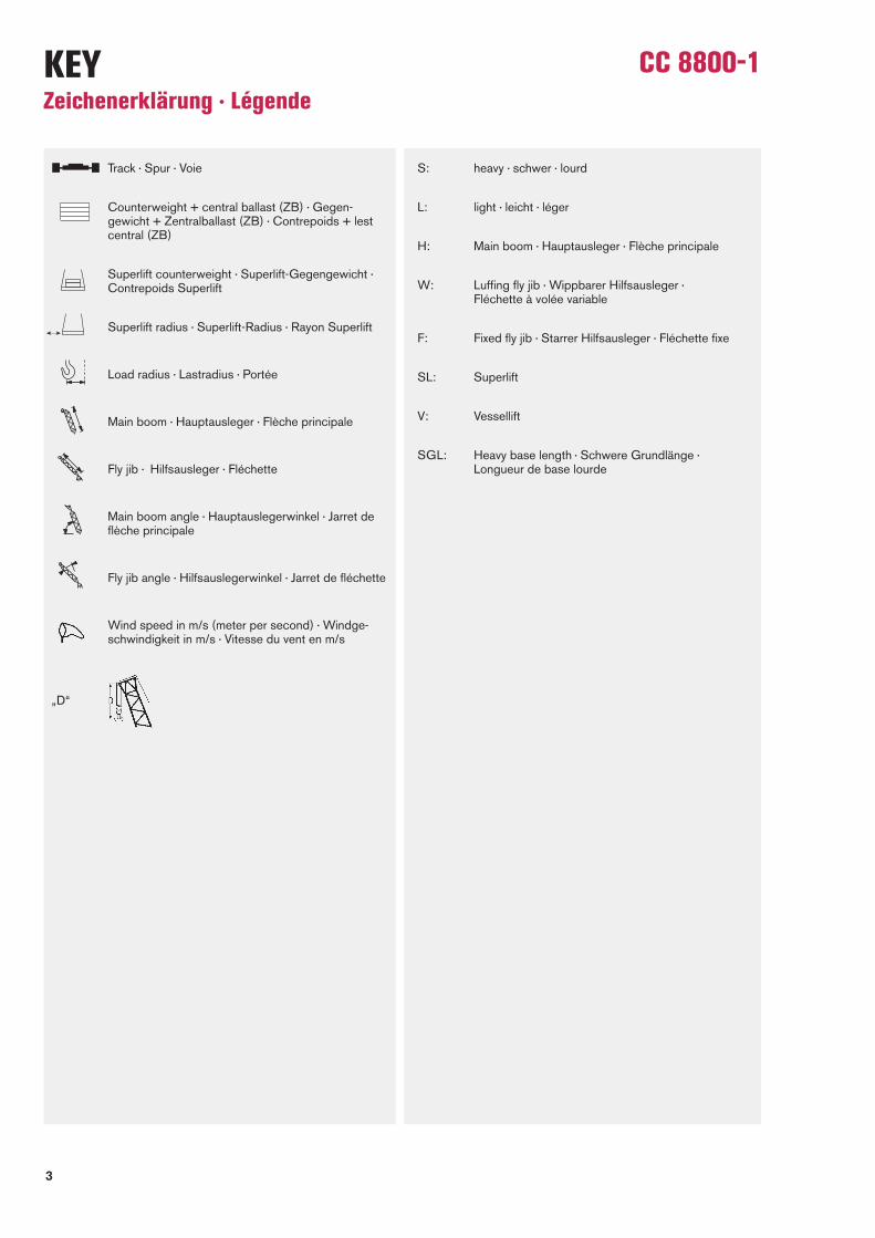
CC 8800-1KEYZeichenerklärung · Légende
Track · Spur · Voie
Counterweight + central ballast (ZB) · Gegen -gewicht + Zentralballast (ZB) · Contrepoids + lestcentral (ZB)
Superlift counterweight · Superlift-Gegengewicht ·Contrepoids Superlift
Superlift radius · Superlift-Radius · Rayon Superlift
Load radius · Lastradius · Portée
Main boom · Hauptausleger · Flèche principale
Fly jib · Hilfsausleger · Fléchette
Main boom angle · Hauptauslegerwinkel · Jarret deflèche principale
Fly jib angle · Hilfsauslegerwinkel · Jarret de fléchette
Wind speed in m/s (meter per second) · Windge-schwindigkeit in m/s · Vitesse du vent en m/s
„D“
S: heavy · schwer · lourd
L: light · leicht · léger
H: Main boom · Hauptausleger · Flèche principale
W: Luffing fly jib · Wippbarer Hilfsausleger · Fléchette à volée variable
F: Fixed fly jib · Starrer Hilfsausleger · Fléchette fixe
SL: Superlift
V: Vessellift
SGL: Heavy base length · Schwere Grundlänge · Longueur de base lourde

4
CC 8800-1HIGHLIGHTS
Features:Max. capacity 1600 t Max. load moment 24002 mt Superlift radii 19-30 m Excellent capacities at the luffing fly jib Redundant drivelines 400 V power supply Optional TWIN-Kit for capacities up to 3200 t
Max. Tragfähigkeit 1600 t Max. Lastmoment 24002 mt Superliftradien 19-30 m Ausgezeichnete Tragfähigkeiten am wippbaren Hilfs ausleger Redundante Antriebseinheiten 400 V Stromaggregat Optionales TWIN-Kit für Tragfähigkeiten bis 3200 t
Capacité maximale de 1600 t Moment de charge maximum 24002 mt Radius superlift 19-30 m Excellentes capacités avec la volée variable Double unité d’entraînement Groupe électrogène de 400 VEn option le kit TWIN pour des capacités jusqu’à 3200 t

5
CC 8800-1SPECIFICATIONS Technische Daten · Caractéristiques
Mechanisms Rope ø Speeds1) Single line pull2) Length of hoist ropeAntriebe Seil-ø Geschwindigkeiten1) Seilzug je Strang2) Länge des HubseilsMécanismes ø du câble Vitesses1) Effort sur brin simple2) Longueur du câble de levage
1) top layers · oberste Lagen · couches supérieures2) without / with reeving effect considered · Angabe ohne / mit Wirkungsgrad der Einscherung · sans / avec effort de mouflage
Working speeds (infinitely variable) · Arbeitsgeschwindigkeiten (stufenlos regelbar) · Vitesses de travail (réglables sans paliers)
Hoist I+II (H1+H2)Hubwerk I+II (H1+H2) 40 mm max. 120 m / min 352 kN / 316 kN 1540 mTreuil de levage I+II (H1+H2)
Runner winch R (H3) – optionRunnerwinde R (H3) – Option 40 mm max. 190 m / min 352 kN 1700 mTambour potence R (H3) – option
Boom derricking (W2)Wippwerk Hauptausleger (W2) 40 mm max. 120 m / minVariation de flèche (W2)
Boom hoist (E)Einziehwerk (E) 40 mm max. 140 m / minRelevage de flèche (E)
Jib luffing (W1)Wippwerk Hilfsausleger (W1) 40 mm max. 105 m / minVariation de volée (W1)
Slewing (rpm)Drehwerk (U /min) 0 – 0,6 1/minOrientation (tr /mn)

6
CC 8800-1SPECIFICATIONS Technische Daten · Caractéristiques
Carrier performance · Fahrleistungen · Performances du porteur
1st gear · 1. Gang · 1ère vitesse max. 0,4 km/h
2nd gear · 2. Gang · 2ème vitesse max. 0,8 km/h
7
CC 8800-1SPECIFICATIONS Technische Daten · Caractéristiques
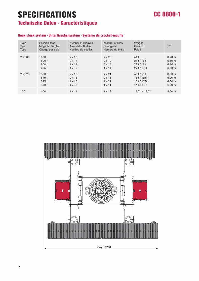
Type Possible load Number of sheaves Number of lines WeightTyp Mögliche Traglast Anzahl der Rollen Strangzahl Gewicht „D“Type Charge possible Nombre de poulies Nombre de brins Poids
Hook block system · Unterflaschensystem · Système de crochet-moufle
2 x 800 1600 t 2 x 13 2 x 26 44 t 8,70 m1800 t 2 x 17 2 x 12 28 t / 18 t 6,50 m1800 t 1 x 13 2 x 12 28 t / 18 t 6,20 m1495 t 1 x 17 1 x 14 22 t / 8,5 t 6,50 m
2 x 675 1350 t 2 x 10 2 x 21 40 t / 21 t 8,50 m1675 t 2 x 15 2 x 11 16 t / 12,5 t 6,00 m1675 t 1 x 10 1 x 21 16 t / 12,5 t 6,00 m1370 t 1 x 15 1 x 11 14,5 t / 8 t 6,00 m
100 1100 t 1 x 11 1 x 13 17,7 t / 13,7 t 4,50 m

8
CC 8800-1SPECIFICATIONS Technische Daten · Caractéristiques
* Option

9
CC 8800-1
30,5 t
41,0 t
43,0 t
50,3 t(34,0 t without slew ring · ohne Rollen dreh- verbindung · sans couronne d’orientation)
26,0 t
90,0 t(46,0 t + 44,0 t)
SPECIFICATIONS Technische Daten · Caractéristiques

10
CC 8800-1BOOM COMBINATIONS Ausleger-Kombinationen · Combinaisons de flèche

11
CC 8800-1BOOM COMBINATIONS Ausleger-Kombinationen · Combinaisons de flèche
On request · Auf Anfrage · Sur demande!

12
CC 8800-1SUPERLIFT CONFIGURATIONS Superlift-Konfigurationen · Combinaisons Superlift
Standard Superlift attachment · Serienmäßige Superlifteinrichtung · Superlift de série
Variable Superlift attachment · Variable Superlifteinrichtung · Superlift variable

13
CC 8800-1SSL, HSSL, SSL/LSL

14
CC 8800-1SSL, HSSL
19-30 m 10,5 m 9.8 m/s 360° ISO295 t + 60 t ZB
m10111214161820222426283034384246505455586062656670
m10111214161820222426283034384246505455586062656670
t 1600,01585,51571,01496,01428,01309,01192,01091,0
991,0912,0830,0751,0620,0538,0449,0
----------
t 1600,01581,01562,01487,01419,01309,01192,01085,0
992,0913,0845,0785,0687,0580,0491,0436,0367,0
--------
t 799,0726,5654,0551,0474,0414,0367,0323,0282,0249,0222,0199,0163,0136,0116,0
99,586,075,073,0
------
t 1555,01553,01553,01478,01410,01302,01185,01079,0
986,0907,0839,0779,0682,0604,0532,0457,0392,0353,0339,0
------
t -
684,0623,0527,0455,0398,0353,0315,0278,0245,0218,0195,0159,0132,0111,0
94,080,068,566,259,555,5
----
t -
1405,01405,01383,01383,01290,01178,01073,0
980,0901,0833,0774,0676,0599,0536,0484,0424,0369,0356,2324,0312,0
----
t -
651,0594,0505,0436,0383,0339,0303,0273,0242,0215,0192,0156,0129,0108,0
90,076,064,061,654,550,646,841,9
--
t -
1238,01238,01238,01238,01204,01168,01069,0
976,0897,0829,0770,0672,0594,0532,0479,0435,0394,0382,0346,0324,0302,0278,0
--
t --
568,0484,0419,0368,0326,0292,0263,0239,0213,0190,0154,0126,0104,0
87,072,060,558,050,546,442,337,135,429,8
t --
1098,01098,01098,01098,01060,01038,0
973,0893,0825,0766,0668,0591,0528,0476,0431,0393,0385,0361,0342,5324,0294,7285,0249,0
0t-640t
78 m
0 t0t-640t
72 m
0 t0t-640t
66 m
0 t0t-640t
60 m
0 t0t-640t
54 m
0t-640t
48 m
m121314161820222426283034384246505458626670727476787981828690919496
m121314161820222426283034384246505458626670727476787981828690919496
t 543,0503,0463,0402,0353,0314,0281,0253,0229,0208,0187,0150,0123,0100,0
82,568,055,545,837,330,224,221,719,217,0
---------
t 976,0976,0976,0976,0976,0973,0940,0927,0888,0820,0761,0663,0586,0523,0471,0426,0388,0355,0327,0301,0267,0251,5236,0220,0
---------
t -
479,0445,0387,0340,0302,0270,0244,0220,0200,0183,0149,0121,0
98,580,565,553,543,234,627,220,918,215,513,211,010,0
-------
t -
867,0867,0867,0867,0867,0858,0846,0829,0818,0759,0661,0583,0521,0468,0423,0385,0353,0324,0300,0278,0265,0252,0238,0224,0217,0203,0
------
t -
459,0426,0371,0327,0290,0260,0234,0212,0192,0175,0146,0118,0
95,077,062,049,739,430,623,116,613,811,1
----------
t -
775,0775,0775,0775,0775,0774,0766,0759,0747,0743,0657,0579,0516,0464,0419,0381,0348,0320,0295,0274,0264,0254,0244,0234,0227,7215,2209,0185,0
----
t --
409,0357,0314,0279,0250,0225,0203,0184,0168,0140,0115,0
92,073,558,546,536,127,219,613,010,1
-----------
t --
695,0695,0695,0695,0695,0692,0687,0683,0674,0653,0576,0513,0461,0416,0378,0345,0316,0292,0270,0260,0250,0241,5233,0229,2221,7218,0196,0175,0169,0
--
t --
392,0342,0302,0268,0240,0215,0194,0176,0160,0133,0111,0
90,071,556,544,333,824,817,010,3
------------
t --
625,0625,0625,0625,0625,0624,0621,0617,0613,0600,0569,0510,0458,0413,0375,0342,0314,0289,0267,0257,0247,0238,5230,0226,0218,0214,0200,0183,0178,2164,0154,0
0t-640t
108 m
0 t0t-640t
102 m
0 t0t-640t
96 m
0 t0t-640t
90 m
0 t0t-640t
84 m
0 t

15
CC 8800-1
m16182022242628303438424650545862667074788286909498
102106110114118122
m16182022242628303438424650545862667074788286909498
102106110114118122
t 333,0295,0263,0235,0212,0191,0174,0158,0131,0110,0
91,072,557,545,234,625,617,811,1
-------------
t 562,0562,0562,0562,0562,0561,0559,0556,0552,0529,0504,0459,0415,0376,0343,0315,0290,0268,0248,0231,0215,0201,0188,0175,0158,0141,0
-----
t 321,0284,0252,0226,0203,0184,0166,0151,0125,0104,0
87,070,555,042,832,123,015,2
--------------
t 506,0506,0506,0506,0506,0506,0504,0501,0495,0489,0458,0438,0412,0374,0341,0312,0287,0265,0245,0228,0212,0198,0185,0173,0163,0147,0132,0
----
t 311,0276,0246,0220,0198,0179,0162,0147,0122,0102,0
85,070,556,043,532,823,715,8
--------------
t 457,0457,0457,0456,0456,0456,0453,0447,0435,0423,0405,0388,0370,0352,0334,0312,0287,0265,0245,0228,0212,0198,0185,0173,0162,0153,0140,0126,0
---
t 300,0266,0237,0212,0191,0173,0156,0142,0117,0
97,580,566,554,542,431,722,514,6
--------------
t 410,0410,0410,0410,0410,0410,0410,0410,0409,0408,0403,0388,0365,0352,0339,0311,0286,0264,0244,0226,0210,0196,0183,0171,0160,0151,0141,0131,0119,0
--
t -
258,0230,0206,0185,0167,0151,0137,0113,0
94,077,563,552,040,830,020,812,8
--------------
t -
369,0369,0369,0369,0369,0369,0369,0368,0367,0366,0355,0344,0323,0313,0303,0284,0262,0242,0224,0208,0194,0181,0169,0158,0148,0139,0131,0122,0111,0
99,5
0t-640t
138 m
0 t0t-640t
132 m
0 t0t-640t
126 m
0 t0t-640t
120 m
0 t0t-640t
114 m
0 t
SSL/LSL
19-30 m 10,5 m 9.8 m/s 360° ISO295 t + 60 t ZB

16
CC 8800-1
m182022242628303438424650545862667074788286909498
102106110114118122126130134138
m182022242628303438424650545862667074788286909498
102106110114118122126130134138
t 248,0221,0198,0179,0161,0145,0132,0108,0
89,073,059,548,037,829,019,711,7
------------------
t 331,0331,0331,0331,0331,0331,0331,0331,0330,0329,0323,0313,0304,0290,0279,0270,0260,0240,0223,0207,0193,0179,0168,0157,0147,0137,0129,0121,0114,0103,0
93,0---
t 243,0217,0195,0175,0158,0143,0130,0107,0
88,572,559,047,938,029,220,512,5
------------------
t 299,0299,0299,0299,0299,0299,0299,0298,0296,0294,0291,0283,0276,0269,0262,0250,0244,0237,0223,0207,0193,0180,0168,0157,0147,0138,0129,0122,0114,0108,0
98,088,5
--
t 234,0209,0187,0169,0152,0137,0124,0102,0
83,568,055,044,034,125,417,811,0
------------------
t 268,0268,0268,0268,0267,0267,0267,0265,0262,0259,0256,0251,0246,0240,0235,0229,0221,0215,0210,0205,0192,0179,0167,0156,0146,0136,0128,0120,0112,0106,0
99,590,581,572,5
0t-640t
156 m
0 t0t-640t
150 m
0 t0t-640t
144 m
0 t
SSL/LSL
19-30 m 10,5 m 9.8 m/s 360° ISO295 t + 60 t ZB

17
CC 8800-1SWSL

18
CC 8800-1SWSL / SFSL 15°
* Main boom angle 88° · Hauptauslegerwinkel 88° · Jarret de flèche principale 88° see page 19 · siehe Seite 19 · voir page 19
m182022242628303437384246505152545861626466697074767882
54 m + 36 m
t ---
291,0268,0249,0231,0197,0175,5169,0146,0
----------------
t 629,0614,0594,0653,0639,0603,0543,0450,0398,5383,0332,0
----------------
t --------
613,0582,0478,0403,0348,0336,5325,0
------------
t -------------
424,0414,0397,0360,0325,0
---------
t -------------------
291,0280,0265,0
-----
t -----------------------
222,0215,0
--
t ---
640,0640,0640,0640,0632,0611,5598,0532,0477,0431,0420,5410,0389,0345,0315,7306,0288,5271,0247,7240,0220,0208,0196,0170,0
***
85° 85° 75° 65° 55° 45°
SFSLSWSL0 t 0 t -640 t
m22242628303438424346505458596266707273747880828586879094
54 m + 48 m
t -,0-,0-,0
233,0217,0190,0165,0143,0138,5125,0111,0
99,0 ----------------
t 496,0484,0471,0516,0508,0484,0411,0356,0344,5313,0278,0244,0
----------------
t --------
490,0434,0373,0326,0289,0281,0259,0
-------------
t -------------
354,0333,0297,0265,0252,0
----------
t ------------------
241,0237,0222,0215,0
------
t -----------------------
181,0178,0176,0
--
t ---
504,0504,0504,0504,0496,0488,0463,0431,0393,0358,0349,5324,0291,0260,0246,5239,7233,0208,0197,5190,0177,2173,0167,7152,0132,0
***
m30343638424650545658626670747678828690919498
102105106110114
54 m + 72 m
t --
157,0148,0132,0118,0106,0
95,089,584,575,568,061,055,052,0
------------
t 315,0306,0328,0325,0320,0314,0283,0253,0240,0227,0206,0187,0171,0157,0146,0
------------
t --------
314,0295,0263,0236,0213,0193,0185,0176,0162,0149,0
---------
t -------------
241,0229,0218,0198,0180,0165,0161,5152,0
------
t -------------------
174,0166,0157,0148,0
----
t -----------------------
127,0125,0118,0
-
t --
321,0321,0321,0321,0321,0315,0309,5304,0286,0269,0253,0239,0233,0227,0215,0196,0178,0173,5160,0145,0136,0126,2123,0109,0
95,5
**
m262830323438424649505458626466677074788286909294959899
102106
54 m + 60 m
t ---
191,0179,0158,0141,0124,0113,5110,0
97,587,578,575,0
---------------
t 394,0386,0378,0411,0406,0396,0367,0322,0293,5285,0255,0229,0208,0197,0
---------------
t --------
400,0385,0336,0297,0264,0250,0238,0232,0215,0195,0
-----------
t ---------------
296,0271,0243,0220,0200,0
---------
t -------------------
205,0193,0182,0176,0
------
t ------------------------
153,0146,0144,0
--
t ---
401,0401,0401,0401,0401,0391,0387,0363,0340,0319,0310,0301,0295,2278,0251,0227,0204,0184,0167,0161,0155,0150,7138,0134,0122,0105,0
***
85° 85° 75° 65° 55° 45°
SFSLSWSL0 t 0 t -640 t
19-30 m 10,5 m 9.8 m/s 360° ISO295 t + 60 t ZB

19
CC 8800-1
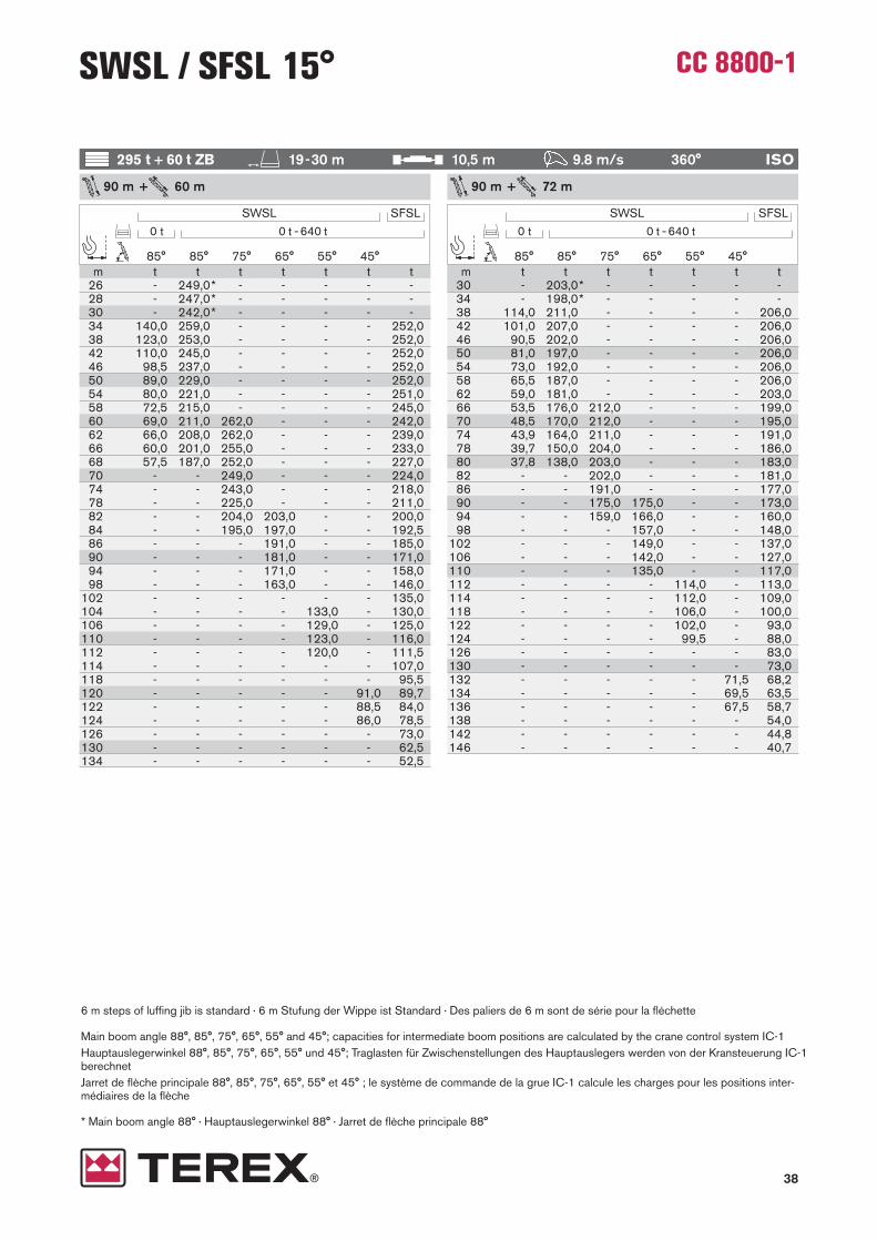
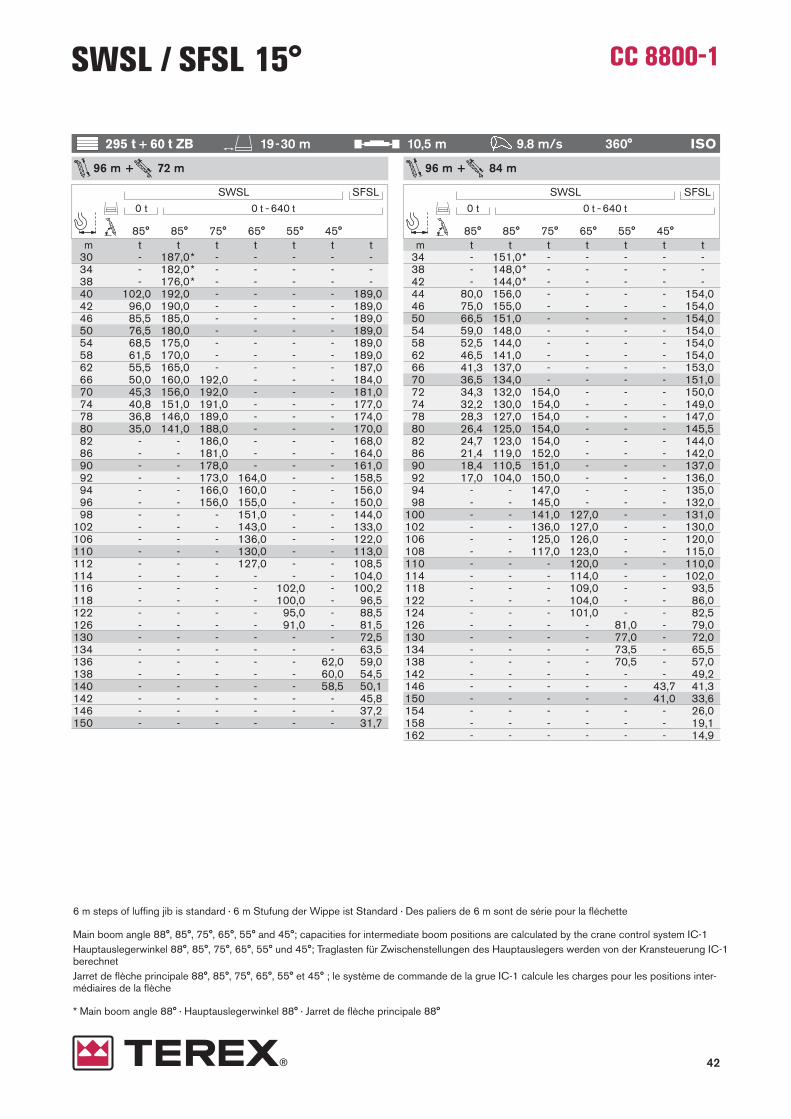
6 m steps of luffing jib is standard · 6 m Stufung der Wippe ist Standard · Des paliers de 6 m sont de série pour la fléchette
Main boom angle 88°, 85°, 75°, 65°, 55° and 45°; capacities for intermediate boom positions are calculated by the crane control system IC-1Haupt aus legerwinkel 88°, 85°, 75°, 65°, 55° und 45°; Traglasten für Zwischen stellungen des Hauptauslegers werden von der Kransteuerung IC-1berechnetJarret de flèche principale 88°, 85°, 75°, 65°, 55° et 45° ; le système de commande de la grue IC-1 calcule les charges pour les positions inter- médiaires de la flèche
* Main boom angle 88° · Hauptauslegerwinkel 88° · Jarret de flèche principale 88°
SWSL / SFSL 15°
m323438404246505458626670747882868890949698
100102106110114116118122126
54 m + 84 m
t ---
128,0120,0107,0
96,086,077,569,561,054,048,142,637,833,631,7
-------------
t 254,0253,0247,0261,0260,0256,0252,0247,0221,0199,0181,0165,0151,0138,0127,0115,5109,0
-------------
t ---------
254,0229,0207,0187,0170,0155,0142,0136,0131,0121,0116,0
----------
t --------------
191,0174,0166,0159,0145,0139,0134,0128,0123,0114,0
------
t ---------------------
143,0139,0131,0124,0114,0
----
t --------------------------
100,097,592,5
-
t ---
258,0258,0258,0258,0258,0256,0248,0240,0226,0212,0200,0190,0180,0175,5171,0162,0156,0150,0143,0136,0123,0115,0105,0
99,093,081,570,0
***
85° 85° 75° 65° 55° 45°
SFSLSWSL0 t 0 t -640 t
m3638424446505458626668707478828690949698
102106108110114118122126130132134138
54 m + 96 m
t ---
105,099,088,078,570,563,056,553,550,544,739,134,229,825,822,320,6
-------------
t 201,0200,0197,0203,0203,0200,0198,0196,0193,0179,0171,0163,0148,0136,0124,5114,5105,5
97,594,0
-------------
t ----------
193,0193,0185,0168,0153,0140,0128,0118,0113,0109,0100,0
93,089,5
---------
t ----------------
156,0143,0137,0131,0120,0111,0106,0102,0
94,587,5
------
t -----------------------
119,0111,0103,0
95,588,0
----
t -------------------------- -
81,577,075,0
--
t ---
203,0203,0203,0201,0200,0199,0195,0193,5192,0188,0184,0173,0164,0155,0147,0143,0139,0133,0126,0122,0118,0107,0100,0
91,581,071,066,261,551,5
***
85° 85° 75° 65° 55° 45°
SFSLSWSL0 t 0 t -640 t
19-30 m 10,5 m 9.8 m/s 360° ISO295 t + 60 t ZB

20
CC 8800-1SWSL / SFSL 15°
6 m steps of luffing jib is standard · 6 m Stufung der Wippe ist Standard · Des paliers de 6 m sont de série pour la fléchette
Main boom angle 88°, 85°, 75°, 65°, 55° and 45°; capacities for intermediate boom positions are calculated by the cranecontrol system IC-1Haupt aus legerwinkel 88°, 85°, 75°, 65°, 55° und 45°; Traglasten für Zwischen stellungen des Hauptauslegers werden vonder Kran steuerung IC-1 berechnetJarret de flèche principale 88°, 85°, 75°, 65°, 55° et 45° ;le système de commande de la grue IC-1 calcule les charges pour lespositions inter médiaires de la flèche
* Main boom angle 88° · Hauptauslegerwinkel 88° · Jarret de flèche principale 88°
m404246485054586266707478828688909498
100102106108110114118120122126128130134136138142144146150
54 m + 108 m
t ---
85,580,571,563,556,049,944,239,034,229,324,922,820,917,314,012,5
------------------
t 154,0154,0151,0155,0154,0152,0150,0148,0146,0145,0143,0131,0120,0110,0105,0101,0
93,085,582,078,772,770,0
---------------
t ----------
143,0143,0143,0135,0129,0124,0113,0104,0100,0
96,088,084,581,075,069,066,5
-----------
t -----------------
124,0121,0116,0106,0102,0
97,590,083,079,576,570,568,0
--------
t -------------------------
94,590,583,580,077,071,068,5
-----
t --------------------------------
62,058,557,0
--
t ---
155,0154,0154,0152,0151,0149,0147,0144,0142,0139,0137,0136,0135,0132,0125,0121,5118,0112,0109,0106,0101,0
96,593,791,084,580,777,068,564,059,551,547,343,234,8
***
85° 85° 75° 65° 55° 45°
SFSLSWSL0 t 0 t -640 t
m2224262830343842454650545862646670747576788284868990929498
60 m + 48 m
t ---
225,0209,0183,0162,0141,0127,5123,0109,0
97,5-- -- -- -- -- -- -- -- -
t 457,0446,0434,0476,0468,0453,0419,0362,0327,5317,0281,0248,0
-- -- -- -- -- -- -- -- -
t --------
464,0461,0394,0342,0302,0269,0255,0
- -- -- -- -- -- -- -
t -------------
327,0316,0305,0284,0255,0248,0
- -- -- -- -- -
t -------------------
235,0227,0213,0207,0
-- -- --
t ------------------------
164,0161,0157,0
--
t ---
463,0463,0463,0463,0462,0447,0441,0418,0389,0354,0324,0310,5297,0274,0247,0240,7234,5222,0199,0188,0177,0162,2159,0153,5148,0129,0
***
m182022242628303438394246505254586263666770727478808286
60 m + 36 m
t ---
280,0259,0240,0223,0195,0166,0160,5144,0
----------------
t 573,0564,0545,0600,0587,0574,0556,0459,0389,0375,0337,0
----------------
t ---------
568,0513,0429,0367,0341,0
-------------
t --------------
390,0360,0334,0328,0
---------
t -------------------
282,0267,0258,0
-----
t -----------------------
202,0196,0
--
t ---
584,0584,0584,0584,0584,0570,0562,0527,0473,0426,0406,0386,0352,0322,0313,7289,0281,0257,0242,5228,0202,0191,5184,0165,0
***
85° 85° 75° 65° 55° 45°
SFSLSWSL0 t 0 t -640 t
19-30 m 10,5 m 9.8 m/s 360° ISO295 t + 60 t ZB

21
CC 8800-1
6 m steps of luffing jib is standard · 6 m Stufung der Wippe ist Standard · Des paliers de 6 m sont de série pour la fléchette
Main boom angle 88°, 85°, 75°, 65°, 55° and 45°; capacities for intermediate boom positions are calculated by the crane control system IC-1Haupt aus legerwinkel 88°, 85°, 75°, 65°, 55° und 45°; Traglasten für Zwischen stellungen des Hauptauslegers werden von der Kransteuerung IC-1berechnetJarret de flèche principale 88°, 85°, 75°, 65°, 55° et 45° ; le système de commande de la grue IC-1 calcule les charges pour les positions inter- médiaires de la flèche
* Main boom angle 88° · Hauptauslegerwinkel 88° · Jarret de flèche principale 88°
SWSL / SFSL 15°
m2628303234384246505254586266697074767882869094959899
102103106110
60 m + 60 m
t ---
184,0172,0152,0136,0122,0108,0102,0
96,586,077,570,0
----------------
t 364,0357,0350,0380,0376,0367,0357,0333,0295,0278,0264,0238,0216,0182,0
----------------
t ---------
384,0360,0316,0282,0253,0234,5229,0208,0199,0
------------
t --------------
286,0282,0264,0252,0240,0218,0199,0
---------
t --------------------
198,0186,0176,0174,0
------
t -------------------------
139,0134,0132,0
--
t ---
370,0370,0370,0370,0370,0363,0354,5347,0334,0321,0302,0284,0278,0257,0248,0239,0217,0196,0177,0158,0153,7141,0137,7131,0127,7118,0103,0
***
85° 85° 75° 65° 55° 45°
SFSLSWSL0 t 0 t -640 t
m3034363842465054586266707476777882869094959698
102106110114118122
60 m + 72 m
t --
152,0143,0127,0113,0102,0
92,083,074,566,559,553,550,5
---------------
t 293,0284,0304,0303,0297,0292,0285,0266,0239,0216,0197,0180,0158,0147,0
---------------
t --------
310,0284,0254,0229,0208,0199,0194,5190,0174,0160,0
-----------
t --------------
243,0241,0218,0198,0181,0166,0162,5159,0
-------
t --------------------
168,0166,0161,0152,0144,0
----
t -------------------------
115,0110,0
--
t --
298,0298,0298,0298,0298,0295,0286,0278,0268,0260,0251,0245,5242,7240,0223,0207,0188,0171,0167,0163,0155,0139,0125,0114,0106,0
93,080,0
**
85° 85° 75° 65° 55° 45°
SFSLSWSL0 t 0 t -640 t
19-30 m 10,5 m 9.8 m/s 360° ISO295 t + 60 t ZB

22
CC 8800-1
6 m steps of luffing jib is standard · 6 m Stufung der Wippe ist Standard · Des paliers de 6 m sont de série pour la fléchette
Main boom angle 88°, 85°, 75°, 65°, 55° and 45°; capacities for intermediate boom positions are calculated by the crane control system IC-1Haupt aus legerwinkel 88°, 85°, 75°, 65°, 55° und 45°; Traglasten für Zwischen stellungen des Hauptauslegers werden von der Kransteuerung IC-1berechnetJarret de flèche principale 88°, 85°, 75°, 65°, 55° et 45° ; le système de commande de la grue IC-1 calcule les charges pour les positions inter- médiaires de la flèche
* Main boom angle 88° · Hauptauslegerwinkel 88° · Jarret de flèche principale 88°
SWSL / SFSL 15°
m323438404246505458626466707478828688909498
102104106108110114118120122126130134
60 m + 84 m
t ---
123,0116,0103,0
92,082,574,067,063,559,552,546,741,336,532,330,4
------------- --
t 237,0236,0230,0244,0243,0240,0236,0232,0228,0210,0200,0190,0173,0159,0146,0133,0117,5109,0
------------- --
t ----------
242,0242,0223,0202,0183,0167,0153,0147,0141,0130,0120,0
---------- --
t ----------------
192,0183,0175,0160,0147,0135,0130,0125,0120,0
------ --
t ----------------------
139,0135,0131,0127,0121,0115,0
--- --
t ------------------------ ----
93,591,587,0
--
t ---
240,0240,0240,0240,0240,0240,0235,0232,0229,0223,0217,0211,0204,0193,0188,5184,0175,0159,0145,0138,0131,0124,5118,0105,0
96,092,789,579,068,057,0
***
85° 85° 75° 65° 55° 45°
SFSLSWSL0 t 0 t -640 t
m36384244465054586266707478828690929498
100102106110114118120122126128130134136138142
60 m + 96 m
t ---
101,095,084,575,067,060,053,548,042,837,933,028,624,722,921,218,116,7
------------ --
t 190,0189,0185,0193,0193,0190,0188,0186,0184,0181,0171,0156,0143,0131,5121,0111,5107,0101,5
89,783,5
------------ --
t ----------
185,0185,0181,0165,0151,0138,0133,0127,0117,0113,0108,0100,0
93,0--------- --
t ----------------
165,0158,0144,0138,0133,0122,0113,0104,0
96,593,0
------ --
t -----------------------
116,0109,0106,0103,0
98,095,0
--- --
t ------------------------ -----
77,573,572,0
--
t ---
192,0192,0192,0191,0191,0190,0187,0184,0181,0178,0174,0171,0167,0163,0159,0151,0147,5144,0137,0126,0114,0102,0
97,092,082,579,576,569,064,259,550,0
***
85° 85° 75° 65° 55° 45°
SFSLSWSL0 t 0 t -640 t
19-30 m 10,5 m 9.8 m/s 360° ISO295 t + 60 t ZB

23
CC 8800-1SWSL / SFSL 15°
6 m steps of luffing jib is standard · 6 m Stufung der Wippe ist Standard · Des paliers de 6 m sont de série pour la fléchette
Main boom angle 88°, 85°, 75°, 65°, 55° and 45°; capacities for intermediate boom positions are calculated by the cranecontrol system IC-1Haupt aus legerwinkel 88°, 85°, 75°, 65°, 55° und 45°; Traglasten für Zwischen stellungen des Hauptauslegers werden vonder Kran steuerung IC-1 berechnetJarret de flèche principale 88°, 85°, 75°, 65°, 55° et 45° ;le système de commande de la grue IC-1 calcule les charges pour lespositions inter médiaires de la flèche
* Main boom angle 88° · Hauptauslegerwinkel 88° · Jarret de flèche principale 88°
m40424648505458626670747678828486909498
100102106108110114118122126130132134138140142146148150154
60 m + 108 m
t ---
81,576,568,060,053,047,141,536,534,231,927,825,823,719,716,112,911,4
------------ ------
t 147,0146,0143,0147,0147,0145,0144,0142,0140,0138,0137,0136,0135,0127,0121,0116,5107,5
99,091,287,584,075,771,0
--------- ------
t -----------
135,0135,0135,0135,0135,0134,0123,0113,0108,0104,0
95,592,088,081,575,569,5
----- ------
t -------------------
119,0119,0117,0112,0108,0
99,592,085,078,572,570,0
-- ------
t ------------------------ --
97,091,586,583,580,574,571,5
-----
t ------------------------ ----- ----
59,556,054,5
--
t ---
147,0147,0147,0146,0144,0143,0141,0139,0138,0137,0135,0133,5132,0130,0128,0125,0124,0123,0121,0118,5116,0110,0105,0
96,586,577,072,569,064,060,757,549,545,541,533,4
***
85° 85° 75° 65° 55° 45°
SFSLSWSL0 t 0 t -640 t
m2224262830343842464750545862646670747778808286879093949698
102
66 m + 48 m
t ---
216,0202,0177,0156,0139,0122,0118,0107,0
95,5------------ ------
t 424,0419,0408,0445,0441,0427,0412,0368,0321,0311,5285,0255,0
------------ ------
t ---------
441,0417,0360,0316,0280,0265,0251,0
-------- ------
t --------------
308,0297,0278,0261,0249,0
----- ------
t --------------------
222,0215,0202,0200,0
------
t ------------------------ -
154,0152,0148,0
--
t ---
433,0433,0433,0433,0433,0422,0416,5401,0383,0349,0319,0306,0293,0269,0248,0234,5230,0219,5209,0187,0182,0167,0152,7148,0139,0133,0123,0
***
m1820222426283034384142465054565862667071747678828690
66 m + 36 m
t ---
270,0249,0231,0216,0189,0164,0147,5142,0
------------ ---
t 536,0528,0511,0562,0551,0539,0528,0469,0396,0354,5342,0
------------ ---
t ---------
537,0530,0457,0388,0335,0
--------- ---
t --------------
366,0352,0326,0304,0
----- ---
t -------------------
264,0252,0244,0
- ---
t ------------------------ --
t ---
546,0546,0546,0546,0546,0538,0520,0513,0468,0421,0381,0363,5346,0316,0290,0267,0260,5241,0228,0215,0190,0167,0153,0
***
85° 85° 75° 65° 55° 45°
SFSLSWSL0 t 0 t -640 t
19-30 m 10,5 m 9.8 m/s 360° ISO295 t + 60 t ZB

24
CC 8800-1
6 m steps of luffing jib is standard · 6 m Stufung der Wippe ist Standard · Des paliers de 6 m sont de série pour la fléchette
Main boom angle 88°, 85°, 75°, 65°, 55° and 45°; capacities for intermediate boom positions are calculated by the crane control system IC-1Haupt aus legerwinkel 88°, 85°, 75°, 65°, 55° und 45°; Traglasten für Zwischen stellungen des Hauptauslegers werden von der Kransteuerung IC-1berechnetJarret de flèche principale 88°, 85°, 75°, 65°, 55° et 45° ; le système de commande de la grue IC-1 calcule les charges pour les positions inter- médiaires de la flèche
* Main boom angle 88° · Hauptauslegerwinkel 88° · Jarret de flèche principale 88°
SWSL / SFSL 15°
m262830323438424650545862667072747882868889909498
102103106107110114
66 m + 60 m
t ---
177,0166,0147,0131,0117,0106,0
95,084,576,068,5
-----------------
t 344,0337,0331,0357,0355,0346,0337,0328,0299,0267,0240,0218,0188,0
-----------------
t ---------
367,0332,0294,0263,0237,0226,0215,0197,0
-------------
t --------------
266,0257,0242,0228,0210,0201,0
----------
t --------------------
191,0188,0177,0168,0
------
t ------------------------ -
130,0125,0124,0
--
t ---
349,0349,0349,0349,0349,0345,0333,0318,0306,0294,0274,0263,5253,0234,0217,0202,0193,5189,2185,0167,0150,0134,0130,2119,0115,2109,0
98,5
***
85° 85° 75° 65° 55° 45°
SFSLSWSL0 t 0 t -640 t
m30343638424650545860626670747880828688909498
100102106110114118119122126
66 m + 72 m
t --
146,0137,0122,0109,0
98,088,580,076,072,565,058,052,047,0
----------------
t 277,0269,0288,0287,0282,0276,0270,0264,0244,0232,0220,0200,0183,0162,0139,0
----------------
t ---------
295,0293,0267,0240,0217,0198,0189,0181,0166,0159,0
------------
t ---------------
230,0223,0210,0202,0193,0177,0162,0156,0
--------
t ---------------------
162,0158,0153,0145,0138,0
-----
t ------------------------ --
107,0101,0100,0
--
t --
282,0282,0282,0282,0282,0282,0274,0269,0265,0257,0248,0240,0232,0225,5219,0203,0196,0189,0176,0162,0154,0146,0132,0118,0105,0
95,093,288,076,5
**
85° 85° 75° 65° 55° 45°
SFSLSWSL0 t 0 t -640 t
19-30 m 10,5 m 9.8 m/s 360° ISO295 t + 60 t ZB

25
CC 8800-1
6 m steps of luffing jib is standard · 6 m Stufung der Wippe ist Standard · Des paliers de 6 m sont de série pour la fléchette
Main boom angle 88°, 85°, 75°, 65°, 55° and 45°; capacities for intermediate boom positions are calculated by the crane control system IC-1Haupt aus legerwinkel 88°, 85°, 75°, 65°, 55° und 45°; Traglasten für Zwischen stellungen des Hauptauslegers werden von der Kransteuerung IC-1berechnetJarret de flèche principale 88°, 85°, 75°, 65°, 55° et 45° ; le système de commande de la grue IC-1 calcule les charges pour les positions inter- médiaires de la flèche
* Main boom angle 88° · Hauptauslegerwinkel 88° · Jarret de flèche principale 88°
SWSL / SFSL 15°
m3234384042465054586266707478828688909498
100102106108110114118120122124126130134138
66 m + 84 m
t ---
118,0111,0
98,588,079,070,563,557,051,045,339,935,231,029,1
---------------- -
t 224,0224,0218,0232,0232,0228,0225,0221,0217,0213,0194,0177,0161,0148,0135,0120,0112,0
---------------- -
t ----------
232,0232,0211,0191,0174,0160,0153,0146,0135,0124,0119,0
------------ -
t ----------------
195,0187,0170,0156,0149,0143,0132,0127,0122,0
-------- -
t -----------------------
132,0128,0121,0115,0112,0
----- -
t ------------------------ -- ---
84,081,577,0
- -
t ---
228,0228,0228,0228,0228,0228,0224,0219,0214,0209,0203,0198,0193,0189,5186,0173,0161,0155,5150,0137,0130,5124,0111,0100,0
94,288,583,078,572,564,054,0
***
85° 85° 75° 65° 55° 45°
SFSLSWSL0 t 0 t -640 t
m363842444650545862667072747882869092949698
100102106110112114118122126130132134136138140142146150
66 m + 96 m
t ---
96,090,580,071,563,556,550,545,142,540,135,631,427,323,521,720,018,416,915,5
---------------- -
t 181,0180,0176,0185,0185,0183,0180,0178,0175,0173,0170,0167,0159,0146,0134,0123,0113,5109,0103,7
98,592,085,5
---------------- -
t -----------
178,0178,0178,0173,0157,0144,0138,0132,0127,0122,0117,0112,0104,0
96,592,5
------------ -
t -------------------
159,0154,0147,0141,0130,0119,0115,0110,0102,0
94,5--------- -
t ------------------------ -- -
110,0104,0
98,593,591,5
------ -
t ------------------------ -- --- ----
65,564,062,5
-- -
t ---
183,0183,0183,0183,0183,0183,0182,0178,0176,5175,0172,0169,0166,0162,0160,5159,0157,0155,0152,5150,0140,0131,0125,0119,0107,0
97,086,576,571,767,064,261,558,555,546,937,9
***
85° 85° 75° 65° 55° 45°
SFSLSWSL0 t 0 t -640 t
19-30 m 10,5 m 9.8 m/s 360° ISO295 t + 60 t ZB

26
CC 8800-1
6 m steps of luffing jib is standard · 6 m Stufung der Wippe ist Standard · Des paliers de 6 m sont de série pour la fléchette
Main boom angle 88°, 85°, 75°, 65°, 55° and 45°; capacities for intermediate boom positions are calculated by the crane control system IC-1Haupt aus legerwinkel 88°, 85°, 75°, 65°, 55° und 45°; Traglasten für Zwischen stellungen des Hauptauslegers werden von der Kransteuerung IC-1berechnetJarret de flèche principale 88°, 85°, 75°, 65°, 55° et 45° ; le système de commande de la grue IC-1 calcule les charges pour les positions inter- médiaires de la flèche
* Main boom angle 88° · Hauptauslegerwinkel 88° · Jarret de flèche principale 88°
SWSL / SFSL 15°
m202224262830343842444650545658596266687074787982868789909498
72 m + 36 m
t --
259,0240,0223,0208,0182,0162,0140,0131,0
--------------------
t 484,0469,0511,0505,0494,0484,0463,0404,0347,0324,0
--------------------
t --------
502,0497,0474,0411,0353,0329,0
----------------
t ---------------
337,0318,0297,0287,0
-----------
t --------------------
243,0229,0226,0
-------
t ------------------------ -
174,0169,0
---
t --
498,0498,0498,0498,0498,0498,0480,0466,0455,0417,0376,0359,0342,0334,2311,0285,0273,5262,0241,0223,0217,2200,0178,0172,7162,2157,0137,0127,0
**
85° 85° 75° 65° 55° 45°
SFSLSWSL0 t 0 t -640 t
m404246485054586266707478828486909498
100102104106110112114118122126130134138142144146150152154158162
66 m + 108 m
t ---
77,572,564,056,550,044,038,733,829,425,423,521,718,314,911,810,3
--------------------
t 141,0140,0138,0142,0142,0140,0139,0137,0135,0134,0132,0131,0127,0124,0119,0109,0100,2
92,789,085,582,077,568,063,0
---------------
t -----------
131,0131,0131,0131,0130,0128,0117,0112,0108,0103,0
99,592,088,084,578,572,5
------------
t --------------------
114,0114,0114,0110,0105,0
97,590,083,077,071,0
---------
t ------------------------ ---
92,086,582,077,573,571,5
------
t ------------------------ ---------
51,048,747,5
---
t ---
142,0142,0142,0141,0140,0138,0137,0135,0133,0131,0130,0129,0126,0124,0122,0121,0120,0119,0118,0115,0114,0113,0110,0100,0
91,081,572,563,555,552,250,045,841,938,130,422,5
***
85° 85° 75° 65° 55° 45°
SFSLSWSL0 t 0 t -640 t
19-30 m 10,5 m 9.8 m/s 360° ISO295 t + 60 t ZB

27
CC 8800-1
6 m steps of luffing jib is standard · 6 m Stufung der Wippe ist Standard · Des paliers de 6 m sont de série pour la fléchette
Main boom angle 88°, 85°, 75°, 65°, 55° and 45°; capacities for intermediate boom positions are calculated by the crane control system IC-1Haupt aus legerwinkel 88°, 85°, 75°, 65°, 55° und 45°; Traglasten für Zwischen stellungen des Hauptauslegers werden von der Kransteuerung IC-1berechnetJarret de flèche principale 88°, 85°, 75°, 65°, 55° et 45° ; le système de commande de la grue IC-1 calcule les charges pour les positions inter- médiaires de la flèche
* Main boom angle 88° · Hauptauslegerwinkel 88° · Jarret de flèche principale 88°
SWSL / SFSL 15°
m26283032343842465054586266707478828690929498
102106108110111114118
72 m + 60 m
t ---
170,0159,0141,0126,0113,0101,0
92,083,074,567,0
----------------
t317,0311,0305,0330,0328,0320,0311,0302,0293,0270,0243,0220,0193,0
----------------
t ---------
335,0333,0307,0274,0246,0223,0203,0
-------------
t --------------
251,0236,0222,0209,0198,0
----------
t -------------------
178,0173,0165,0157,0
------
t ------------------------
120,0117,0115,0
--
t ---
321,0321,0321,0321,0321,0321,0311,0301,0288,0279,0269,0249,0230,0213,0197,0183,0176,5170,0156,0140,0125,0118,0111,0107,6
97,589,5
***
85° 85° 75° 65° 55° 45°
SFSLSWSL0 t 0 t -640 t
m22242628303438424648505458626667687074788082838690949798
100102106
72 m + 48 m
t ---
208,0194,0170,0151,0134,0120,0112,0105,0
94,0 -------------------
t390,0385,0376,0409,0405,0392,0378,0365,0326,0306,0288,0257,0
-------------------
t ---------
414,0414,0380,0331,0292,0261,0254,0247,0
--------------
t ---------------
285,0280,0271,0254,0239,0232,0
----------
t ----------------------
206,0197,0187,0
------
t ------------------------ --
144,0142,0138,0
--
t ---
397,0397,0397,0397,0397,0392,0384,0375,0359,0345,0315,0288,0282,0276,0264,0244,0225,0216,5208,0204,2193,0174,0156,0143,2139,0130,5122,0109,0
***
85° 85° 75° 65° 55° 45°
SFSLSWSL0 t 0 t -640 t
19-30 m 10,5 m 9.8 m/s 360° ISO295 t + 60 t ZB

28
CC 8800-1
6 m steps of luffing jib is standard · 6 m Stufung der Wippe ist Standard · Des paliers de 6 m sont de série pour la fléchette
Main boom angle 88°, 85°, 75°, 65°, 55° and 45°; capacities for intermediate boom positions are calculated by the crane control system IC-1Haupt aus legerwinkel 88°, 85°, 75°, 65°, 55° und 45°; Traglasten für Zwischen stellungen des Hauptauslegers werden von der Kransteuerung IC-1berechnetJarret de flèche principale 88°, 85°, 75°, 65°, 55° et 45° ; le système de commande de la grue IC-1 calcule les charges pour les positions inter- médiaires de la flèche
* Main boom angle 88° · Hauptauslegerwinkel 88° · Jarret de flèche principale 88°
SWSL / SFSL 15°
m3034363842465054586062667074788286909498
102106110112114118122126130
72 m + 72 m
t --
140,0131,0117,0104,0
94,084,576,573,069,563,056,550,545,6
--------------
t257,0249,0266,0266,0261,0256,0250,0244,0238,0235,0224,0204,0186,0166,0143,0
--------------
t ---------
272,0272,0269,0251,0227,0206,0188,0172,0157,0
-----------
t ---------------
217,0204,0193,0183,0172,0158,0
--------
t --------------------
151,0144,0137,0133,0
-----
t -------------------------
99,594,5
--
t --
260,0260,0260,0260,0260,0260,0256,0252,5249,0242,0234,0228,0221,0215,0199,0185,0172,0160,0149,0137,0123,0116,5110,0
98,586,577,571,0
**
85° 85° 75° 65° 55° 45°
SFSLSWSL0 t 0 t -640 t
m343842465054586266707478828688909498
102106110112114118122124126130134138142
72 m + 84 m
t --
106,094,084,075,067,060,554,048,843,838,533,829,727,8
----------------
t208,0202,0216,0212,0208,0205,0201,0197,0193,0179,0164,0150,0137,5123,0115,0
----------------
t --------
216,0216,0216,0200,0182,0166,0159,0152,0140,0129,0118,0
------------
t ---------------
184,0174,0165,0152,0140,0129,0124,0119,0
--------
t ---------------------
123,0120,0114,0108,0105,0
-----
t ---------------------------
75,071,0
--
t --
211,0211,0211,0211,0211,0210,0206,0202,0198,0194,0188,0183,0181,0179,0169,0157,0146,0136,0127,0121,0115,0103,0
92,587,282,071,562,557,549,6
**
85° 85° 75° 65° 55° 45°
SFSLSWSL0 t 0 t -640 t
19-30 m 10,5 m 9.8 m/s 360° ISO295 t + 60 t ZB

29
CC 8800-1
6 m steps of luffing jib is standard · 6 m Stufung der Wippe ist Standard · Des paliers de 6 m sont de série pour la fléchette
Main boom angle 88°, 85°, 75°, 65°, 55° and 45°; capacities for intermediate boom positions are calculated by the crane control system IC-1Haupt aus legerwinkel 88°, 85°, 75°, 65°, 55° und 45°; Traglasten für Zwischen stellungen des Hauptauslegers werden von der Kransteuerung IC-1berechnetJarret de flèche principale 88°, 85°, 75°, 65°, 55° et 45° ; le système de commande de la grue IC-1 calcule les charges pour les positions inter- médiaires de la flèche
* Main boom angle 88° · Hauptauslegerwinkel 88° · Jarret de flèche principale 88°
SWSL / SFSL 15°
m36384246505458626670727478828688909498
100102106110112114118120122124126130134136138140142146150154
72 m + 96 m
t ---
86,076,067,560,053,547,642,239,837,433,029,025,323,622,018,815,814,4
-------------------
t167,0167,0164,0173,0170,0168,0166,0163,0161,0158,0157,0156,0148,0136,0125,0120,0115,5105,5
94,088,0
-------------------
t ----------
168,0168,0168,0168,0164,0157,0150,0138,0127,0121,0117,0108,0100,0
96,0---------------
t ------------------
150,0150,0150,0137,0126,0121,0117,0108,0104,0100,0
96,0 ----------
t --------------------------
106,0103,0100,0
97,592,587,585,5
------
t ----------------------------------
59,558,054,5
--
t---
170,0170,0170,0170,0170,0170,0167,0166,0165,0162,0159,0157,0155,0153,0150,0147,0145,5144,0137,0127,0122,5118,0110,0105,0100,0
94,789,580,070,566,061,557,052,547,942,333,9
***
85° 85° 75° 65° 55° 45°
SFSLSWSL0 t 0 t -640 t
m404246505458626670747880828690949698
102106110112114118122124126130134136138142146148150154156158162166
72 m + 108 m
t ---
68,560,553,046,841,035,831,126,824,822,919,416,113,011,6
-----------------------
t133,0132,0130,0134,0132,0131,0129,0127,0125,0123,0121,0120,0119,0116,5110,5102,0
98,094,287,079,069,564,5
------------------
t ----------
124,0124,0124,0124,0124,0124,0124,0122,0112,0103,0
95,091,588,081,075,072,0
--------------
t -------------------
109,0109,0109,0109,0103,0
95,091,588,081,075,072,5
----------
t ---------------------------
85,580,578,576,072,068,566,5
------
t ----------------------------------
44,441,740,8
---
t ---
133,0133,0133,0132,0131,0129,0128,0125,0124,0123,0121,0119,0117,0116,0115,0113,0110,0108,0107,0106,0104,0101,0
97,093,083,575,070,566,058,050,046,243,039,436,433,526,218,9
***
85° 85° 75° 65° 55° 45°
SFSLSWSL0 t 0 t -640 t
19-30 m 10,5 m 9.8 m/s 360° ISO295 t + 60 t ZB

30
CC 8800-1
6 m steps of luffing jib is standard · 6 m Stufung der Wippe ist Standard · Des paliers de 6 m sont de série pour la fléchette
Main boom angle 88°, 85°, 75°, 65°, 55° and 45°; capacities for intermediate boom positions are calculated by the crane control system IC-1Haupt aus legerwinkel 88°, 85°, 75°, 65°, 55° und 45°; Traglasten für Zwischen stellungen des Hauptauslegers werden von der Kransteuerung IC-1berechnetJarret de flèche principale 88°, 85°, 75°, 65°, 55° et 45° ; le système de commande de la grue IC-1 calcule les charges pour les positions inter- médiaires de la flèche
* Main boom angle 88° · Hauptauslegerwinkel 88° · Jarret de flèche principale 88°
SWSL / SFSL 15°
m2022242628303438424446505458616266707174777882869091939498
102
78 m + 36 m
t ---
230,0214,0200,0175,0156,0138,0129,0
--------------------
t449,0436,0422,0469,0459,0449,0429,0410,0353,0329,0
--------------------
t ---------
463,0463,0427,0373,0323,0
----------------
t --------------
316,0311,0289,0270,0266,0
-----------
t --------------------
224,0220,0208,0
-------
t -------------------------
161,0156,0
---
t ---
460,0460,0460,0460,0460,0451,0439,0427,0408,0372,0337,0314,5307,0280,0257,0251,7236,0222,5218,0201,0184,0164,0159,2149,7145,0127,0112,0
***
85° 85° 75° 65° 55° 45°
SFSLSWSL0 t 0 t -640 t
m2224262830343842465054565862666869707478828687909498
102104106110114
78 m + 48 m
t ----
186,0163,0145,0129,0116,0103,0
92,087,0
-------------------
t362,0358,0349,0340,0377,0364,0351,0338,0326,0292,0260,0240,0
-------------------
t ---------
386,0379,0370,0348,0305,0271,0257,0
---------------
t ----------------
268,0264,0247,0232,0219,0
----------
t ----------------------
187,0179,0170,0
------
t --------------------------
131,0127,0
---
t ----
368,0368,0368,0368,0367,0355,0339,0333,0327,0310,0284,0272,0266,0260,0239,0220,0203,0188,0184,5174,0161,0144,0128,0120,5113,0
98,589,5
***
85° 85° 75° 65° 55° 45°
SFSLSWSL0 t 0 t -640 t
19-30 m 10,5 m 9.8 m/s 360° ISO295 t + 60 t ZB

31
CC 8800-1
6 m steps of luffing jib is standard · 6 m Stufung der Wippe ist Standard · Des paliers de 6 m sont de série pour la fléchette
Main boom angle 88°, 85°, 75°, 65°, 55° and 45°; capacities for intermediate boom positions are calculated by the crane control system IC-1Haupt aus legerwinkel 88°, 85°, 75°, 65°, 55° und 45°; Traglasten für Zwischen stellungen des Hauptauslegers werden von der Kransteuerung IC-1berechnetJarret de flèche principale 88°, 85°, 75°, 65°, 55° et 45° ; le système de commande de la grue IC-1 calcule les charges pour les positions inter- médiaires de la flèche
* Main boom angle 88° · Hauptauslegerwinkel 88° · Jarret de flèche principale 88°
SWSL / SFSL 15°
m262830343842465054565862667074777880828690949698
102104106110112114116118122126
78 m + 60 m
t ---
153,0135,0120,0108,0
97,588,084,080,073,065,5
---------------------
t293,0290,0285,0307,0298,0290,0282,0273,0265,0259,0246,0222,0195,0
---------------------
t ---------
314,0313,0307,0285,0255,0231,0215,0210,0200,0
----------------
t ---------------
233,0229,0222,0216,0204,0193,0183,0
------------
t ----------------------
162,0158,0150,0146,0
--------
t ----------------------------
111,0108,0105,0
---
t ---
299,0299,0299,0299,0299,0293,0288,5284,0273,0265,0257,0245,0230,7226,0217,5209,0193,0179,0166,0160,0154,0144,0137,0130,0116,0109,5103,0
96,590,078,572,5
***
85° 85° 75° 65° 55° 45°
SFSLSWSL0 t 0 t -640 t
m30343842465054586266707478828690929498
102104106110114116118122126130134
78 m + 72 m
t --
126,0112,0100,0
89,581,073,066,060,054,549,344,1
-----------------
t240,0233,0250,0244,0239,0233,0228,0222,0217,0207,0189,0166,0143,0
-----------------
t --------
254,0254,0250,0236,0214,0196,0179,0163,0152,0
-------------
t --------------
198,0187,0182,0177,0168,0160,0156,0
---------
t ---------------------
137,0130,0124,0122,0
-----
t --------------------------
91,586,5
--
t --
243,0243,0243,0243,0243,0241,0235,0230,0224,0216,0211,0205,0195,0181,0174,5168,0156,0145,0140,0135,0125,0114,0108,0102,0
90,579,568,561,5
**
85° 85° 75° 65° 55° 45°
SFSLSWSL0 t 0 t -640 t
19-30 m 10,5 m 9.8 m/s 360° ISO295 t + 60 t ZB

32
CC 8800-1
6 m steps of luffing jib is standard · 6 m Stufung der Wippe ist Standard · Des paliers de 6 m sont de série pour la fléchette
Main boom angle 88°, 85°, 75°, 65°, 55° and 45°; capacities for intermediate boom positions are calculated by the crane control system IC-1Haupt aus legerwinkel 88°, 85°, 75°, 65°, 55° und 45°; Traglasten für Zwischen stellungen des Hauptauslegers werden von der Kransteuerung IC-1berechnetJarret de flèche principale 88°, 85°, 75°, 65°, 55° et 45° ; le système de commande de la grue IC-1 calcule les charges pour les positions inter- médiaires de la flèche
* Main boom angle 88° · Hauptauslegerwinkel 88° · Jarret de flèche principale 88°
SWSL / SFSL 15°
m3438424650545862666870747882868890929498
102104106110114116118122126128130134138142146
78 m + 84 m
t --
101,089,579,571,063,557,051,048,545,841,136,732,428,326,4
-------------------
t195,0190,0202,0199,0195,0192,0188,0184,0180,0179,0177,0168,0154,0139,5123,0115,0
-------------------
t ---------
202,0202,0202,0202,0190,0174,0166,0159,0153,0147,0135,0122,0114,0
-------------
t -----------------
173,0168,0159,0151,0147,0143,0136,0128,0123,0
---------
t ------------------------
115,0112,0110,0104,0100,0
98,0 -----
t -------------------------------
68,064,5
--
t-,0-,0
198,0198,0198,0198,0198,0197,0194,0192,0190,0187,0183,0178,0174,0172,0170,0167,5165,0153,0142,0137,0132,0123,0114,0109,5105,0
95,084,579,574,565,055,548,844,3
**
85° 85° 75° 65° 55° 45°
SFSLSWSL0 t 0 t -640 t
m363842465054586266707478828486909498
100102106110114118122124126128130134138140142144146150154158
78 m + 96 m
t ---
81,572,063,556,550,044,439,334,630,326,524,723,019,716,713,912,6
-------------------
t157,0157,0153,0162,0160,0158,0156,0153,0151,0148,0146,0143,0138,0135,0129,5118,5106,5
93,787,5
-------------------
t ----------
158,0158,0158,0158,0158,0158,0145,0134,0128,0123,0114,0106,0
94,5---------------
t ------------------
141,0141,0139,0131,0125,0116,0108,0104,0100,0
96,5----------
t -------------------------
97,094,592,090,085,581,079,0
------
t ---------------------------------
53,051,548,8
--
t ---
159,0159,0159,0159,0159,0159,0158,0155,0153,0151,0149,5148,0146,0142,0139,0138,0137,0133,0123,0115,0106,0
99,095,091,086,281,572,563,559,255,051,047,141,137,129,2
***
85° 85° 75° 65° 55° 45°
SFSLSWSL0 t 0 t -640 t
19-30 m 10,5 m 9.8 m/s 360° ISO295 t + 60 t ZB

33
CC 8800-1
6 m steps of luffing jib is standard · 6 m Stufung der Wippe ist Standard · Des paliers de 6 m sont de série pour la fléchette
Main boom angle 88°, 85°, 75°, 65°, 55° and 45°; capacities for intermediate boom positions are calculated by the crane control system IC-1Haupt aus legerwinkel 88°, 85°, 75°, 65°, 55° und 45°; Traglasten für Zwischen stellungen des Hauptauslegers werden von der Kransteuerung IC-1berechnetJarret de flèche principale 88°, 85°, 75°, 65°, 55° et 45° ; le système de commande de la grue IC-1 calcule les charges pour les positions inter- médiaires de la flèche
* Main boom angle 88° · Hauptauslegerwinkel 88° · Jarret de flèche principale 88°
SWSL / SFSL 15°
m404246505458626670747880828690929498
102106108110112114118122126130134138142146150154158160162166170
78 m + 108 m
t ---
64,556,549,643,437,832,828,324,122,220,416,913,812,3
-----------------------
t126,0125,0123,0127,0126,0125,0123,0121,0119,0117,0115,0115,0114,0111,5106,5103,0
99,793,286,578,574,069,064,0
----------------
t -----------
119,0119,0119,0119,0119,0119,0118,0118,0109,0105,0101,0
97,593,586,580,070,5
------------
t --------------------
104,0104,0104,0104,0104,0103,0
95,588,581,576,0
---------
t ----------------------------
78,073,569,566,062,5
------
t ---------------------------------
38,535,934,7
---
t ---
127,0127,0126,0126,0125,0124,0123,0121,0120,0119,0117,0115,0113,5112,0110,0108,0106,0105,0104,0102,5101,0
99,597,590,583,576,067,559,551,544,236,931,629,527,521,514,5
***
85° 85° 75° 65° 55° 45°
SFSLSWSL0 t 0 t -640 t
m202224262830343842444546505458626466707374788182869094959798
102106
84 m + 36 m
t ---
221,0205,0192,0168,0150,0134,0126,0
----------------------
t411,0399,0386,0430,0421,0412,0392,0374,0358,0334,0
----------------------
t ----------
430,0430,0417,0385,0340,0
-----------------
t ----------------
291,0281,0262,0250,0
------------
t ----------------------
202,0199,0188,0
-------
t ---------------------------
147,0143,0
---
t ---
419,0419,0419,0419,0419,0417,0409,0402,5397,0380,0365,0332,0302,0288,5275,0252,0236,2231,0213,0200,2196,0181,0167,0150,0145,7137,2133,0116,0100,0
***
85° 85° 75° 65° 55° 45°
SFSLSWSL0 t 0 t -640 t
19-30 m 10,5 m 9.8 m/s 360° ISO295 t + 60 t ZB

34
CC 8800-1
6 m steps of luffing jib is standard · 6 m Stufung der Wippe ist Standard · Des paliers de 6 m sont de série pour la fléchette
Main boom angle 88°, 85°, 75°, 65°, 55° and 45°; capacities for intermediate boom positions are calculated by the crane control system IC-1Haupt aus legerwinkel 88°, 85°, 75°, 65°, 55° und 45°; Traglasten für Zwischen stellungen des Hauptauslegers werden von der Kransteuerung IC-1berechnetJarret de flèche principale 88°, 85°, 75°, 65°, 55° et 45° ; le système de commande de la grue IC-1 calcule les charges pour les positions inter- médiaires de la flèche
* Main boom angle 88° · Hauptauslegerwinkel 88° · Jarret de flèche principale 88°
SWSL / SFSL 15°
m2426283034384246505254565862667072747882848690949798
102106109110114118
84 m + 48 m
t ---
178,0156,0139,0124,0111,0101,0
95,590,085,0
--------------------
t330,0322,0314,0347,0335,0323,0310,0298,0288,0279,0263,0247,0
--------------------
t ---------
353,0352,0348,0342,0320,0283,0253,0
----------------
t ----------------
248,0240,0225,0212,0206,0
-----------
t ----------------------
171,0162,0156,0
-------
t ---------------------------
119,0115,0
---
t ---
337,0337,0337,0337,0337,0329,0323,5318,0309,0304,0293,0279,0255,0244,5234,0215,0199,0191,0183,0169,0157,0148,0145,0131,0117,0106,5103,0
89,577,5
***
85° 85° 75° 65° 55° 45°
SFSLSWSL0 t 0 t -640 t
m262830343842465054586266687074787982869094969899
102106108110114116118120122126130
84 m + 60 m
t ---
146,0129,0115,0103,0
93,084,076,569,563,560,0
----------------------
t270,0268,0263,0281,0275,0267,0259,0251,0243,0234,0225,0199,0182,0
----------------------
t ---------
289,0284,0279,0275,0266,0239,0217,0212,0198,0
-----------------
t ----------------
219,0209,0197,0187,0177,0172,0
-------------
t -----------------------
148,0143,0136,0133,0
--------
t -----------------------------
101,098,095,5
---
t ---
275,0275,0275,0275,0275,0271,0264,0256,0246,0242,5239,0232,0221,0216,7204,0189,0175,0162,0156,0150,0147,2139,0129,0123,5118,0105,0
99,293,587,581,570,062,0
***
85° 85° 75° 65° 55° 45°
SFSLSWSL0 t 0 t -640 t
19-30 m 10,5 m 9.8 m/s 360° ISO295 t + 60 t ZB

35
CC 8800-1
6 m steps of luffing jib is standard · 6 m Stufung der Wippe ist Standard · Des paliers de 6 m sont de série pour la fléchette
Main boom angle 88°, 85°, 75°, 65°, 55° and 45°; capacities for intermediate boom positions are calculated by the crane control system IC-1Haupt aus legerwinkel 88°, 85°, 75°, 65°, 55° und 45°; Traglasten für Zwischen stellungen des Hauptauslegers werden von der Kransteuerung IC-1berechnetJarret de flèche principale 88°, 85°, 75°, 65°, 55° et 45° ; le système de commande de la grue IC-1 calcule les charges pour les positions inter- médiaires de la flèche
* Main boom angle 88° · Hauptauslegerwinkel 88° · Jarret de flèche principale 88°
SWSL / SFSL 15°
m3034384246505458626466707478828688909498
102106108110114118120122126128130134138142
84 m + 72 m
t --
120,0106,0
95,085,576,569,062,559,556,551,546,742,4
-- - -----------------
t 220,0215,0230,0225,0220,0215,0209,0204,0199,0195,0192,0185,0169,0147,0
-- - -----------------
t ------ - --
233,0233,0232,0226,0222,0202,0185,0177,0170,0150,0
---------------
t ------ - ---------
187,0181,0172,0163,0154,0147,0
------------
t ------ - ---------------
127,0124,0118,0113,0110,0
-------
t ------ - ----------------------
80,078,0
---
t --
224,0224,0224,0224,0224,0224,0219,0216,5214,0210,0205,0198,0193,0188,0182,5177,0164,0152,0141,0131,0126,0121,0112,0103,0
97,792,581,576,571,561,052,047,8
**
85° 85° 75° 65° 55° 45°
SFSLSWSL0 t 0 t -640 t
m34384246505458626670747882868890949698
102104106110114118122126130132134138142146150154
84 m + 84 m
t --
95,585,075,567,060,053,547,942,838,133,930,126,624,9
- - ------------------
t180,0175,0186,0184,0180,0177,0173,0169,0166,0162,0157,0152,0141,0125,0117,0
- - ------------------
t ---------
186,0186,0186,0185,0179,0172,0164,0151,0145,0139,0129,0121,0
--------------
t -----------------
158,0154,0145,0142,0138,0131,0125,0119,0
----------
t ------------------------
103,098,593,589,587,5
------
t ----------------------------- -
60,057,0
---
t --
182,0182,0182,0182,0182,0182,0180,0177,0174,0171,0168,0163,0161,5160,0157,0153,0149,0138,0133,0128,0118,0110,0101,0
94,085,575,571,066,557,548,741,537,229,5
**
85° 85° 75° 65° 55° 45°
SFSLSWSL0 t 0 t -640 t
19-30 m 10,5 m 9.8 m/s 360° ISO295 t + 60 t ZB

36
CC 8800-1
6 m steps of luffing jib is standard · 6 m Stufung der Wippe ist Standard · Des paliers de 6 m sont de série pour la fléchette
Main boom angle 88°, 85°, 75°, 65°, 55° and 45°; capacities for intermediate boom positions are calculated by the crane control system IC-1Haupt aus legerwinkel 88°, 85°, 75°, 65°, 55° und 45°; Traglasten für Zwischen stellungen des Hauptauslegers werden von der Kransteuerung IC-1berechnetJarret de flèche principale 88°, 85°, 75°, 65°, 55° et 45° ; le système de commande de la grue IC-1 calcule les charges pour les positions inter- médiaires de la flèche
* Main boom angle 88° · Hauptauslegerwinkel 88° · Jarret de flèche principale 88°
SWSL / SFSL 15°
m384246505458626670747678808286909498
100102104106110114116118122126128130134138142146148150154158162
84 m + 96 m
t --
76,567,559,552,546,741,236,231,729,627,625,723,920,417,314,411,710,5
--------------------
t145,0142,0150,0148,0146,0143,0141,0138,0136,0133,0132,0131,0129,0127,0123,0117,5108,0
95,789,5
--------------------
t ----------
146,0146,0146,0146,0146,0146,0146,0137,0132,0127,0122,0117,0108,0
99,593,0
--------------
t --------------------
124,0124,0123,0120,0117,0114,0108,0103,0101,0
97,5---------
t ----------------------------
86,084,080,076,073,0
------
t ----------------------------------
46,244,842,0
--
t --
147,0147,0147,0147,0147,0147,0146,0144,0143,0142,0141,0140,0138,0136,0134,0130,0129,0128,0127,0126,0119,0111,0106,5102,0
95,087,584,281,073,064,056,048,144,240,333,028,723,4
**
85° 85° 75° 65° 55° 45°
SFSLSWSL0 t 0 t -640 t
m4042465054586266707478828688909498
102106110112114118122126128130134136138142146150154158162166170
84 m + 108 m
t ---
60,052,545,839,934,529,825,321,417,714,412,8
------------------------
t117,0117,0114,0119,0118,0116,0114,0113,0111,0109,0107,0106,0104,0103,0100,2
94,588,783,277,770,265,5
-----------------
t -----------
112,0112,0112,0112,0112,0112,0112,0112,0104,0100,0
96,089,082,574,569,5
------------
t -------------------
97,597,597,597,597,597,094,592,585,582,579,574,0
-------
t ----------------------------
71,569,566,062,058,555,5
----
t ----------------------------------
31,929,527,3
-
t ---
118,0118,0118,0117,0117,0116,0116,0114,0112,0110,0109,0108,0106,0105,0103,0101,0
98,097,096,094,092,086,583,079,573,070,067,059,051,544,537,330,423,618,614,7
***
85° 85° 75° 65° 55° 45°
SFSLSWSL0 t 0 t -640 t
19-30 m 10,5 m 9.8 m/s 360° ISO295 t + 60 t ZB

37
CC 8800-1
6 m steps of luffing jib is standard · 6 m Stufung der Wippe ist Standard · Des paliers de 6 m sont de série pour la fléchette
Main boom angle 88°, 85°, 75°, 65°, 55° and 45°; capacities for intermediate boom positions are calculated by the crane control system IC-1Haupt aus legerwinkel 88°, 85°, 75°, 65°, 55° und 45°; Traglasten für Zwischen stellungen des Hauptauslegers werden von der Kransteuerung IC-1berechnetJarret de flèche principale 88°, 85°, 75°, 65°, 55° et 45° ; le système de commande de la grue IC-1 calcule les charges pour les positions inter- médiaires de la flèche
* Main boom angle 88° · Hauptauslegerwinkel 88° · Jarret de flèche principale 88°
SWSL / SFSL 15°
m202224262830343842444647505458606266677074767882848689909498
102106110
90 m + 36 m
t ---
212,0197,0184,0162,0144,0129,0122,0
-----------------------
t375,0364,0353,0394,0385,0376,0358,0341,0328,0321,0
-----------------------
t -----------
393,0389,0374,0349,0334,0
-----------------
t ------------------
268,0255,0239,0232,0
-----------
t ------------------------
185,0180,0173,0
------
t ---------------------------------
t ---
381,0381,0381,0381,0381,0381,0377,0370,0367,0352,0340,0328,0312,5297,0271,0265,0247,0227,0217,5208,0191,0183,5176,0165,5162,0150,0136,0121,0106,0
91,0
***
85° 85° 75° 65° 55° 45°
SFSLSWSL0 t 0 t -640 t
m2426283034384246505456586266707274788286909498
100102106110113114118122
90 m + 48 m
t ---
171,0150,0133,0119,0107,0
96,587,583,0
--------------------
t303,0295,0288,0316,0307,0296,0284,0272,0263,0254,0249,0
--------------------
t ---------
321,0317,0313,0303,0293,0263,0249,0
---------------
t ----------------
232,0218,0205,0194,0
-----------
t ---------------------
155,0147,0143,0
-------
t --------------------------
108,0104,0
---
t ---
309,0309,0309,0309,0309,0304,0296,0291,0286,0274,0265,0251,0240,5230,0211,0194,0179,0165,0152,0141,0135,5130,0119,0106,0
96,293,080,568,0
***
85° 85° 75° 65° 55° 45°
SFSLSWSL0 t 0 t -640 t
19-30 m 10,5 m 9.8 m/s 360° ISO295 t + 60 t ZB
38
CC 8800-1
6 m steps of luffing jib is standard · 6 m Stufung der Wippe ist Standard · Des paliers de 6 m sont de série pour la fléchette
Main boom angle 88°, 85°, 75°, 65°, 55° and 45°; capacities for intermediate boom positions are calculated by the crane control system IC-1Haupt aus legerwinkel 88°, 85°, 75°, 65°, 55° und 45°; Traglasten für Zwischen stellungen des Hauptauslegers werden von der Kransteuerung IC-1berechnetJarret de flèche principale 88°, 85°, 75°, 65°, 55° et 45° ; le système de commande de la grue IC-1 calcule les charges pour les positions inter- médiaires de la flèche
* Main boom angle 88° · Hauptauslegerwinkel 88° · Jarret de flèche principale 88°
SWSL / SFSL 15°
m2628303438424650545860626668707478828486909498
102104106110112114118120122124126130134
90 m + 60 m
t ---
140,0123,0110,0
98,589,080,072,569,066,060,057,5
----------------------
t249,0247,0242,0259,0253,0245,0237,0229,0221,0215,0211,0208,0201,0187,0
----------------------
t ----------
262,0262,0255,0252,0249,0243,0225,0204,0195,0
-----------------
t -----------------
203,0197,0191,0181,0171,0163,0
-------------
t ------------------------
133,0129,0123,0120,0
--------
t ------------------------------
91,088,586,0
---
t ---
252,0252,0252,0252,0252,0251,0245,0242,0239,0233,0227,0224,0218,0211,0200,0192,5185,0171,0158,0146,0135,0130,0125,0116,0111,5107,0
95,589,784,078,573,062,552,5
***
85° 85° 75° 65° 55° 45°
SFSLSWSL0 t 0 t -640 t
m30343842465054586266707478808286909498
102106110112114118122124126130132134136138142146
90 m + 72 m
t --
114,0101,0
90,581,073,065,559,053,548,543,939,737,8
---------------------
t203,0198,0211,0207,0202,0197,0192,0187,0181,0176,0170,0164,0150,0138,0
---------------------
t ---------
212,0212,0211,0204,0203,0202,0191,0175,0159,0
-----------------
t ----------------
175,0166,0157,0149,0142,0135,0
-------------
t ----------------------
114,0112,0106,0102,0
99,5 --------
t -----------------------------
71,569,567,5
---
t --
206,0206,0206,0206,0206,0206,0203,0199,0195,0191,0186,0183,0181,0177,0173,0160,0148,0137,0127,0117,0113,0109,0100,0
93,088,083,073,068,263,558,754,044,840,7
**
85° 85° 75° 65° 55° 45°
SFSLSWSL0 t 0 t -640 t
19-30 m 10,5 m 9.8 m/s 360° ISO295 t + 60 t ZB

39
CC 8800-1
6 m steps of luffing jib is standard · 6 m Stufung der Wippe ist Standard · Des paliers de 6 m sont de série pour la fléchette
Main boom angle 88°, 85°, 75°, 65°, 55° and 45°; capacities for intermediate boom positions are calculated by the crane control system IC-1Haupt aus legerwinkel 88°, 85°, 75°, 65°, 55° und 45°; Traglasten für Zwischen stellungen des Hauptauslegers werden von der Kransteuerung IC-1berechnetJarret de flèche principale 88°, 85°, 75°, 65°, 55° et 45° ; le système de commande de la grue IC-1 calcule les charges pour les positions inter- médiaires de la flèche
* Main boom angle 88° · Hauptauslegerwinkel 88° · Jarret de flèche principale 88°
SWSL / SFSL 15°
m3438424650545862667072747882848688909498
102106110114118120122126130134138142146150154158
90 m + 84 m
t --
90,580,071,063,056,050,044,739,837,535,331,227,525,824,122,5
-------------------
t166,0161,0171,0169,0165,0162,0158,0155,0151,0148,0146,0143,0139,0134,5132,0125,5119,0
-------------------
t ----------
170,0170,0170,0169,0169,0168,0166,0164,0155,0143,0132,0119,0
--------------
t -------------------
148,0140,0133,0126,0120,0114,0111,0
----------
t --------------------------
92,087,583,580,0
------
t -------------------------------
52,049,4
---
t --
168,0168,0168,0168,0168,0168,0167,0164,0162,5161,0159,0156,0155,0154,0150,0149,0146,0143,0134,0124,0115,0106,0
98,094,090,083,075,566,558,049,841,633,528,723,7
**
85° 85° 75° 65° 55° 45°
SFSLSWSL0 t 0 t -640 t
m3842465054586266707478828690949698
100102106110114118122126130132134138142146150152154158162166170
90 m + 96 m
t --
72,063,556,049,243,338,033,128,824,921,318,014,912,110,8
----------------------
t135,0132,0137,0136,0134,0131,0129,0126,0124,0121,0119,0116,0112,0108,5105,0103,0
97,291,5
--------------------
t ----------
133,0133,0133,0133,0132,0132,0132,0131,0130,0120,0111,0103,0
92,0---------------
t -------------------
115,0115,0114,0109,0104,0
99,094,592,5
-----------
t -------------------------
78,076,074,570,567,564,5
-------
t --------------------------------
39,037,735,2
---
t --
136,0136,0136,0136,0136,0136,0136,0133,0131,0128,0126,0123,0120,0119,0118,0115,5114,0111,0109,0106,0
99,091,084,077,074,071,064,056,048,440,837,133,526,220,015,910,6
**
85° 85° 75° 65° 55° 45°
SFSLSWSL0 t 0 t -640 t
19-30 m 10,5 m 9.8 m/s 360° ISO295 t + 60 t ZB

40
CC 8800-1
6 m steps of luffing jib is standard · 6 m Stufung der Wippe ist Standard · Des paliers de 6 m sont de série pour la fléchette
Main boom angle 88°, 85°, 75°, 65°, 55° and 45°; capacities for intermediate boom positions are calculated by the crane control system IC-1Haupt aus legerwinkel 88°, 85°, 75°, 65°, 55° und 45°; Traglasten für Zwischen stellungen des Hauptauslegers werden von der Kransteuerung IC-1berechnetJarret de flèche principale 88°, 85°, 75°, 65°, 55° et 45° ; le système de commande de la grue IC-1 calcule les charges pour les positions inter- médiaires de la flèche
* Main boom angle 88° · Hauptauslegerwinkel 88° · Jarret de flèche principale 88°
SWSL / SFSL 15°
m404246505458626670747882848688909498
102106110112114118122126128130134138140142144146150154158162166170
90 m + 108 m
t ---
56,048,642,236,531,326,722,518,715,213,511,910,4
-------------------------
t108,0108,0106,0110,0109,0107,0105,0104,0102,0100,0
98,596,796,095,094,091,787,583,279,074,769,767,0
------------------
t ------------
104,0104,0104,0104,0104,0104,0104,0103,0103,0103,0
99,091,584,578,073,5
-------------
t ----------------------
89,589,589,589,589,588,083,579,577,576,074,5
-------
t ------------------------------
62,060,559,057,554,551,548,8
---
t -------------------------------------
25,223,021,0
t ---
109,0109,0109,0108,0108,0107,0107,0106,0104,0103,0102,0101,5101,0
99,097,596,094,091,090,289,587,586,083,079,576,069,563,560,758,054,551,044,037,130,423,817,411,1
***
85° 85° 75° 65° 55° 45°
SFSLSWSL0 t 0 t -640 t
m202224262830343842464850545862666970747882868890939498
102104106110114118
96 m + 36 m
t ---
202,0188,0176,0155,0137,0123,0111,0
-----------------------
t342,0333,0323,0355,0351,0343,0326,0310,0299,0287,0
-----------------------
t ----------
361,0357,0347,0334,0318,0
------------------
t ----------------
251,0247,0231,0217,0
-------------
t ----------------------
166,0162,0156,0
--------
t ----------------------------
117,0114,0
---
t ---
346,0346,0346,0346,0346,0346,0340,0334,0329,0313,0302,0291,0266,0248,0242,0222,0203,0186,0171,0164,0157,0148,0145,0133,0122,0115,0108,0
94,080,567,5
***
85° 85° 75° 65° 55° 45°
SFSLSWSL0 t 0 t -640 t
19-30 m 10,5 m 9.8 m/s 360° ISO295 t + 60 t ZB

41
CC 8800-1
6 m steps of luffing jib is standard · 6 m Stufung der Wippe ist Standard · Des paliers de 6 m sont de série pour la fléchette
Main boom angle 88°, 85°, 75°, 65°, 55° and 45°; capacities for intermediate boom positions are calculated by the crane control system IC-1Haupt aus legerwinkel 88°, 85°, 75°, 65°, 55° und 45°; Traglasten für Zwischen stellungen des Hauptauslegers werden von der Kransteuerung IC-1berechnetJarret de flèche principale 88°, 85°, 75°, 65°, 55° et 45° ; le système de commande de la grue IC-1 calcule les charges pour les positions inter- médiaires de la flèche
* Main boom angle 88° · Hauptauslegerwinkel 88° · Jarret de flèche principale 88°
SWSL / SFSL 15°
m242628303438424650545658626670747778828690949798
102104106110114117118122126130
96 m + 48 m
t ---
163,0143,0127,0113,0101,0
92,083,579,5
-----------------------
t277,0270,0263,0290,0282,0270,0259,0248,0240,0231,0227,0
-----------------------
t ---------
292,0292,0291,0279,0272,0264,0245,0
------------------
t ----------------
214,0211,0198,0187,0177,0
-------------
t ----------------------
140,0139,0132,0129,0
--------
t ----------------------------
95,592,0
----
t ---
281,0281,0281,0281,0281,0280,0272,0268,0264,0254,0245,0237,0225,0211,5207,0190,0174,0160,0147,0138,7136,0125,0120,0115,0106,0
94,085,082,070,559,051,0
***
85° 85° 75° 65° 55° 45°
SFSLSWSL0 t 0 t -640 t
m2628303438424650545860626668707478828486909498
100102106110114116118122126128130134138
96 m + 60 m
t ---
133,0117,0104,0
93,584,076,068,565,562,556,554,0
----------------------
t229,0226,0222,0235,0232,0225,0217,0210,0202,0196,0193,0190,0184,0181,0
----------------------
t ----------
237,0237,0235,0234,0231,0223,0219,0211,0202,0
-----------------
t -------------------
184,0174,0165,0156,0152,0
------------
t -------------------------
122,0116,0111,0108,0
-------
t -------------------------------
78,076,0
---
t ---
231,0231,0231,0231,0231,0231,0227,0224,0221,0216,0213,5211,0203,0198,0192,0186,5181,0166,0153,0141,0135,5130,0120,0111,0102,0
98,294,584,574,068,763,553,544,6
***
85° 85° 75° 65° 55° 45°
SFSLSWSL0 t 0 t -640 t
19-30 m 10,5 m 9.8 m/s 360° ISO295 t + 60 t ZB
42
CC 8800-1
6 m steps of luffing jib is standard · 6 m Stufung der Wippe ist Standard · Des paliers de 6 m sont de série pour la fléchette
Main boom angle 88°, 85°, 75°, 65°, 55° and 45°; capacities for intermediate boom positions are calculated by the crane control system IC-1Haupt aus legerwinkel 88°, 85°, 75°, 65°, 55° und 45°; Traglasten für Zwischen stellungen des Hauptauslegers werden von der Kransteuerung IC-1berechnetJarret de flèche principale 88°, 85°, 75°, 65°, 55° et 45° ; le système de commande de la grue IC-1 calcule les charges pour les positions inter- médiaires de la flèche
* Main boom angle 88° · Hauptauslegerwinkel 88° · Jarret de flèche principale 88°
SWSL / SFSL 15°
m30343840424650545862667074788082869092949698
102106110112114116118122126130134136138140142146150
96 m + 72 m
t ---
102,096,085,576,568,561,555,550,045,340,836,835,0
------------------------
t187,0182,0176,0192,0190,0185,0180,0175,0170,0165,0160,0156,0151,0146,0141,0
------------------------
t ----------
192,0192,0191,0189,0188,0186,0181,0178,0173,0166,0156,0
------------------
t ------------------
164,0160,0155,0151,0143,0136,0130,0127,0
-------------
t ---------------------------
102,0100,0
95,091,0
--------
t ---------------------------------
62,060,058,5
---
t ---
189,0189,0189,0189,0189,0189,0187,0184,0181,0177,0174,0170,0168,0164,0161,0158,5156,0150,0144,0133,0122,0113,0108,5104,0100,2
96,588,581,572,563,559,054,550,145,837,231,7
***
85° 85° 75° 65° 55° 45°
SFSLSWSL0 t 0 t -640 t
m343842444650545862667072747880828690929498
100102106108110114118122124126130134138142146150154158162
96 m + 84 m
t ---
80,075,066,559,052,546,541,336,534,332,228,326,424,721,418,417,0
---------------------
t151,0148,0144,0156,0155,0151,0148,0144,0141,0137,0134,0132,0130,0127,0125,0123,0119,0110,5104,0
---------------------
t -----------
154,0154,0154,0154,0154,0152,0151,0150,0147,0145,0141,0136,0125,0117,0
---------------
t ---------------------
127,0127,0126,0123,0120,0114,0109,0104,0101,0
----------
t ------------------------------
81,077,073,570,5
------
t -----------------------------------
43,741,0
---
t ---
154,0154,0154,0154,0154,0154,0153,0151,0150,0149,0147,0145,5144,0142,0137,0136,0135,0132,0131,0130,0120,0115,0110,0102,0
93,586,082,579,072,065,557,049,241,333,626,019,114,9
***
85° 85° 75° 65° 55° 45°
SFSLSWSL0 t 0 t -640 t
19-30 m 10,5 m 9.8 m/s 360° ISO295 t + 60 t ZB

43
CC 8800-1
6 m steps of luffing jib is standard · 6 m Stufung der Wippe ist Standard · Des paliers de 6 m sont de série pour la fléchette
Main boom angle 88°, 85°, 75°, 65°, 55° and 45°; capacities for intermediate boom positions are calculated by the crane control system IC-1Haupt aus legerwinkel 88°, 85°, 75°, 65°, 55° und 45°; Traglasten für Zwischen stellungen des Hauptauslegers werden von der Kransteuerung IC-1berechnetJarret de flèche principale 88°, 85°, 75°, 65°, 55° et 45° ; le système de commande de la grue IC-1 calcule les charges pour les positions inter- médiaires de la flèche
* Main boom angle 88° · Hauptauslegerwinkel 88° · Jarret de flèche principale 88°
SWSL / SFSL 15°
m384246485054586266707478828690929498
100102106108110114118120122126130134138142146150154156158162166
96 m + 96 m
t ---
63,059,051,545,339,634,529,925,721,918,515,312,411,0
-----------------------
t124,0121,0118,0125,0125,0123,0120,0117,0115,0113,0110,0108,0105,5102,5
99,598,096,593,592,0
--------------------
t -----------
121,0121,0121,0121,0121,0120,0119,0119,0118,0118,0117,0114,0106,0
96,590,5
-------------
t ---------------------
105,0105,0105,0104,0101,0
99,094,089,585,5
---------
t -----------------------------
68,064,561,558,555,5
-----
t -----------------------------------
31,129,927,6
-
t ---
124,0124,0124,0124,0124,0124,0124,0123,0121,0118,0116,0114,0113,0112,0109,0107,5106,0103,0102,0101,0
98,595,091,087,080,073,066,560,554,547,239,932,829,325,819,012,3
***
85° 85° 75° 65° 55° 45°
SFSLSWSL0 t 0 t -640 t
m424650525458626668707478828486909498
102106110112114116118122126130134138142144146150154158160162166170174
96 m + 108 m
t ---
47,844,538,332,827,925,623,419,415,712,410,8
---------------------------
t99,097,095,0
100,0100,0
98,597,095,094,093,091,589,587,787,086,083,580,577,274,071,067,766,0
-------------------
t -------------
95,095,095,095,095,094,594,594,094,093,592,591,087,080,572,0
-------------
t -----------------------
81,581,581,581,581,579,075,071,569,568,0
--------
t -------------------------------
53,552,049,846,843,942,6
----
t --------------------------------------
17,815,814,0
t ----
100,0100,0
99,599,098,798,598,097,596,095,294,593,091,590,088,587,085,583,082,081,280,579,077,572,065,559,554,051,649,242,335,629,025,822,716,510,5
-
***
85° 85° 75° 65° 55° 45°
SFSLSWSL0 t 0 t -640 t
19-30 m 10,5 m 9.8 m/s 360° ISO295 t + 60 t ZB

44
CC 8800-1
6 m steps of luffing jib is standard · 6 m Stufung der Wippe ist Standard · Des paliers de 6 m sont de série pour la fléchette
Main boom angle 88°, 85°, 75°, 65°, 55° and 45°; capacities for intermediate boom positions are calculated by the crane control system IC-1Haupt aus legerwinkel 88°, 85°, 75°, 65°, 55° und 45°; Traglasten für Zwischen stellungen des Hauptauslegers werden von der Kransteuerung IC-1berechnetJarret de flèche principale 88°, 85°, 75°, 65°, 55° et 45° ; le système de commande de la grue IC-1 calcule les charges pour les positions inter- médiaires de la flèche
* Main boom angle 88° · Hauptauslegerwinkel 88° · Jarret de flèche principale 88°
SWSL / SFSL 15°
m20222426283034384246505458626466707274788082869091949698
102106108110114118122
102 m + 36 m
t ----
180,0168,0148,0131,0118,0106,0
-------------------------
t312,0304,0295,0287,0321,0314,0298,0284,0273,0263,0
-------------------------
t ----------
322,0316,0303,0294,0290,0
--------------------
t -----------------
231,0223,0210,0203,0
--------------
t ------------------------
151,0145,0142,0
--------
t ------------------------------
104,0101,0
---
t ----
314,0314,0314,0314,0314,0312,0303,0293,0280,0271,0266,5262,0238,0227,5217,0198,0190,0182,0166,0153,0149,7140,0134,5129,0118,0108,0101,7
95,583,070,558,5
****
85° 85° 75° 65° 55° 45°
SFSLSWSL0 t 0 t -640 t
m2426283032343842465054565862667074767879828690929498
100102106108110114118119120122126130134
102 m + 48 m
t ----
145,0136,0121,0108,0
97,087,579,075,572,0
--------------------------
t253,0247,0241,0235,0262,0257,0247,0237,0227,0219,0211,0208,0204,0
--------------------------
t -----------
262,0262,0258,0245,0239,0234,0231,0
---------------------
t -------------------
200,0191,0180,0170,0166,0
---------------
t --------------------------
127,0124,0118,0115,0
---------
t ---------------------------------
83,081,5
----
t ----
256,0256,0256,0256,0256,0256,0250,0247,0244,0237,0227,0221,0214,0208,0202,0197,7185,0170,0156,0149,5143,0131,0126,0121,0111,0106,5102,0
93,582,579,777,071,561,050,542,7
****
85° 85° 75° 65° 55° 45°
SFSLSWSL0 t 0 t -640 t
19-30 m 10,5 m 9.8 m/s 360° ISO295 t + 60 t ZB

45
CC 8800-1
6 m steps of luffing jib is standard · 6 m Stufung der Wippe ist Standard · Des paliers de 6 m sont de série pour la fléchette
Main boom angle 88°, 85°, 75°, 65°, 55° and 45°; capacities for intermediate boom positions are calculated by the crane control system IC-1Haupt aus legerwinkel 88°, 85°, 75°, 65°, 55° und 45°; Traglasten für Zwischen stellungen des Hauptauslegers werden von der Kransteuerung IC-1berechnetJarret de flèche principale 88°, 85°, 75°, 65°, 55° et 45° ; le système de commande de la grue IC-1 calcule les charges pour les positions inter- médiaires de la flèche
* Main boom angle 88° · Hauptauslegerwinkel 88° · Jarret de flèche principale 88°
SWSL / SFSL 15°
m28303436384246505458626668707478828688909498
102104106110114118122126130132134138142146
102 m + 60 m
t ---
118,0111,0
99,589,079,572,065,059,053,551,0
-----------------------
t207,0203,0194,0215,0212,0205,0198,0191,0184,0178,0173,0167,0165,0
-----------------------
t ----------
213,0213,0212,0210,0206,0198,0194,0189,0
------------------
t ------------------
173,0168,0159,0150,0143,0139,0
------------
t -------------------------
109,0104,0
99,0 --------
t ------------------------------
68,066,0
----
t ---
211,0211,0211,0211,0211,0211,0208,0204,0200,0197,5195,0191,0183,0179,0174,0168,0162,0149,0137,0127,0121,5116,0107,0
98,590,583,074,064,059,254,545,536,431,1
***
85° 85° 75° 65° 55° 45°
SFSLSWSL0 t 0 t -640 t
m30343840424650545862666870747880828690949698
102106110114118120122126130134138140142144146150154
102 m + 72 m
t ---
96,591,080,572,064,558,052,046,944,442,137,833,932,1
-----------------------
t171,0167,0160,0176,0174,0169,0164,0159,0154,0150,0145,0143,0141,0137,0133,0131,0
-----------------------
t -----------
173,0173,0172,0171,0169,0168,0166,0161,0157,0156,0154,0
-----------------
t --------------------
149,0145,0138,0131,0124,0118,0
-------------
t ---------------------------
91,088,584,581,0
--------
t ---------------------------------
53,051,550,0
---
t ---
173,0173,0173,0173,0173,0173,0172,0170,0168,5167,0164,0161,0159,5158,0152,0149,0145,0142,5140,0129,0119,0109,0100,0
92,588,785,077,571,062,554,050,046,041,937,829,722,6
***
85° 85° 75° 65° 55° 45°
SFSLSWSL0 t 0 t -640 t
19-30 m 10,5 m 9.8 m/s 360° ISO295 t + 60 t ZB

46
CC 8800-1
6 m steps of luffing jib is standard · 6 m Stufung der Wippe ist Standard · Des paliers de 6 m sont de série pour la fléchette
Main boom angle 88°, 85°, 75°, 65°, 55° and 45°; capacities for intermediate boom positions are calculated by the crane control system IC-1Haupt aus legerwinkel 88°, 85°, 75°, 65°, 55° und 45°; Traglasten für Zwischen stellungen des Hauptauslegers werden von der Kransteuerung IC-1berechnetJarret de flèche principale 88°, 85°, 75°, 65°, 55° et 45° ; le système de commande de la grue IC-1 calcule les charges pour les positions inter- médiaires de la flèche
* Main boom angle 88° · Hauptauslegerwinkel 88° · Jarret de flèche principale 88°
SWSL / SFSL 15°
m3438424446505458626670747880828690929498
102106110114118122126128130134138142146150154156158162
102 m + 84 m
t ---
75,070,562,055,048,643,037,933,329,225,423,722,018,916,014,6
--------------------
t139,0136,0132,0142,0141,0138,0134,0131,0127,0124,0120,0117,0114,0113,0111,5108,5105,5104,0
--------------------
t -----------
137,0137,0137,0136,0135,0133,0132,0131,0130,0128,0123,0115,0
---------------
t --------------------
116,0116,0115,0109,0104,0
99,094,5
-----------
t ---------------------------
73,071,067,564,061,5
------
t ---------------------------------
35,332,931,8
--
t ---
140,0140,0140,0140,0140,0140,0140,0138,0135,0132,0130,5129,0126,0124,0122,5121,0116,0113,0110,0107,0
98,090,082,075,071,568,062,055,548,040,433,025,822,218,711,7
***
85° 85° 75° 65° 55° 45°
SFSLSWSL0 t 0 t -640 t
m3842464850545862667072747880828688909498
102104106110114118120122126130134138142146150152154158160162166
102 m + 96 m
t ---
58,054,547,641,536,031,226,724,722,719,117,415,812,711,2
------------------------
t113,0111,0108,0115,0114,0112,0109,0107,0104,0102,0101,0
99,597,096,094,792,291,089,787,285,082,781,5
-------------------
t -------------
109,0109,0109,0109,0109,0108,0107,0106,0106,0105,0104,0103,0
99,595,5
--------------
t -----------------------
94,594,594,594,594,089,085,081,077,0
---------
t -------------------------------
59,055,553,050,549,8
-----
t --------------------------------- -----
23,322,220,2
t ---
114,0114,0114,0114,0113,0113,0113,0112,5112,0110,0109,0108,0106,0105,0104,0102,0100,0
98,595,794,592,590,588,586,083,576,569,563,057,052,545,538,435,031,624,921,618,412,0
***
85° 85° 75° 65° 55° 45°
SFSLSWSL0 t 0 t -640 t
19-30 m 10,5 m 9.8 m/s 360° ISO295 t + 60 t ZB

47
CC 8800-1
6 m steps of luffing jib is standard · 6 m Stufung der Wippe ist Standard · Des paliers de 6 m sont de série pour la fléchette
Main boom angle 88°, 85°, 75°, 65°, 55° and 45°; capacities for intermediate boom positions are calculated by the crane control system IC-1Haupt aus legerwinkel 88°, 85°, 75°, 65°, 55° und 45°; Traglasten für Zwischen stellungen des Hauptauslegers werden von der Kransteuerung IC-1berechnetJarret de flèche principale 88°, 85°, 75°, 65°, 55° et 45° ; le système de commande de la grue IC-1 calcule les charges pour les positions inter- médiaires de la flèche
* Main boom angle 88° · Hauptauslegerwinkel 88° · Jarret de flèche principale 88°
SWSL / SFSL 15°
m424650525458626466707478808286909498
102106110112114118122126130132134138142146148150154158162164166
102 m + 108 m
t ---
43,640,434,429,226,824,520,316,412,811,2
-------------------- ----- -
t90,588,586,591,591,589,588,087,086,084,582,580,580,079,077,075,073,070,768,566,564,263,0
----------- ----- -
t --------------
85,585,585,585,585,584,584,083,583,582,581,580,076,071,0
----- ----- -
t -----------------------
72,572,572,572,572,572,570,567,063,562,0
----- -
t -------------------------------
47,946,344,741,738,936,335,1
-
t --------------------------------- ----- -
t ----
91,091,091,090,790,590,089,588,588,087,586,084,583,082,080,579,077,576,575,573,072,070,568,565,262,056,051,546,943,540,233,627,321,218,215,2
***
85° 85° 75° 65° 55° 45°
SFSLSWSL0 t 0 t -640 t
m20222426283034384246505254586266707478828690949598
100102106110112114118122126
108 m + 36 m
t ----
171,0159,0140,0125,0112,0101,0
----------------------- -
t283,0276,0269,0262,0291,0285,0272,0260,0249,0240,0
----------------------- -
t -----------
288,0288,0280,0266,0259,0
----------------- -
t -----------------
215,0201,0190,0
------------- -
t -----------------------
134,0129,0126,0
------- -
t -----------------------------
90,588,0
-- -
t ----
285,0285,0285,0285,0285,0285,0276,0272,0268,0260,0249,0240,0232,0212,0193,0177,0161,0147,0135,0132,0123,0118,0113,0103,0
94,588,582,571,060,049,0
****
85° 85° 75° 65° 55° 45°
SFSLSWSL0 t 0 t -640 t
19-30 m 10,5 m 9.8 m/s 360° ISO295 t + 60 t ZB

48
CC 8800-1
6 m steps of luffing jib is standard · 6 m Stufung der Wippe ist Standard · Des paliers de 6 m sont de série pour la fléchette
Main boom angle 88°, 85°, 75°, 65°, 55° and 45°; capacities for intermediate boom positions are calculated by the crane control system IC-1Haupt aus legerwinkel 88°, 85°, 75°, 65°, 55° und 45°; Traglasten für Zwischen stellungen des Hauptauslegers werden von der Kransteuerung IC-1berechnetJarret de flèche principale 88°, 85°, 75°, 65°, 55° et 45° ; le système de commande de la grue IC-1 calcule les charges pour les positions inter- médiaires de la flèche
* Main boom angle 88° · Hauptauslegerwinkel 88° · Jarret de flèche principale 88°
SWSL / SFSL 15°
m2426283032343842465054586266707476788286909498
102104106110114118122124126130134138
108 m + 48 m
19-30 m 10,5 m 9.8 m/s 360° ISO295 t + 60 t ZB
t ----
137,0129,0114,0102,0
91,582,574,568,0
-----------------------
t230,0225,0220,0214,0237,0233,0224,0215,0206,0199,0192,0185,0
-----------------------
t -----------
234,0232,0226,0220,0210,0207,0
------------------
t ------------------
183,0173,0163,0154,0
-------------
t ------------------------
113,0110,0105,0
--------
t ------------------------------
70,068,0
---
t ----
233,0233,0233,0233,0233,0233,0229,0224,0218,0213,0204,0198,0195,5193,0181,0165,0151,0138,0127,0116,0111,0106,0
97,088,580,570,565,560,550,541,132,1
****
85° 85° 75° 65° 55° 45°
SFSLSWSL0 t 0 t -640 t
m28303436384246505458626466707478828688909498
102106110114118122126130134136138142146150
108 m + 60 m
t ---
112,0105,0
93,583,575,067,561,055,052,049,945,2
----------------------
t189,0185,0177,0194,0192,0186,0179,0172,0166,0161,0156,0153,0151,0146,0
----------------------
t -----------
192,0192,0189,0185,0180,0176,0170,0167,0
-----------------
t -------------------
161,0152,0144,0137,0130,0
------------
t -------------------------
96,592,087,5
--------
t ------------------------------
57,055,5
----
t ---
191,0191,0191,0191,0191,0191,0190,0187,0185,0183,0179,0175,0171,0165,0161,0159,0157,0145,0133,0122,0112,0103,0
94,086,078,571,562,553,549,245,036,428,020,9
***
85° 85° 75° 65° 55° 45°
SFSLSWSL0 t 0 t -640 t

49
CC 8800-1
19-30 m 10,5 m 9.8 m/s 360° ISO295 t + 60 t ZB
6 m steps of luffing jib is standard · 6 m Stufung der Wippe ist Standard · Des paliers de 6 m sont de série pour la fléchette
Main boom angle 88°, 85°, 75°, 65°, 55° and 45°; capacities for intermediate boom positions are calculated by the crane control system IC-1Haupt aus legerwinkel 88°, 85°, 75°, 65°, 55° und 45°; Traglasten für Zwischen stellungen des Hauptauslegers werden von der Kransteuerung IC-1berechnetJarret de flèche principale 88°, 85°, 75°, 65°, 55° et 45° ; le système de commande de la grue IC-1 calcule les charges pour les positions inter- médiaires de la flèche
* Main boom angle 88° · Hauptauslegerwinkel 88° · Jarret de flèche principale 88°
SWSL / SFSL 15°
m3034384042465054586266707478808286909498
100102106110114118122126130134138142144146148150154158
108 m + 72 m
t ---
90,585,075,567,560,054,048,343,338,734,630,829,1
-----------------------
t155,0151,0146,0159,0158,0153,0148,0143,0139,0134,0130,0126,0123,0119,0118,0
-----------------------
t -----------
156,0155,0153,0152,0151,0148,0145,0142,0139,0136,0
-----------------
t -------------------
126,0126,0126,0123,0118,0113,0107,0
------------
t --------------------------
81,577,574,071,0
--------
t --------------------------------
43,342,040,7
---
t ---
156,0156,0156,0156,0156,0156,0156,0154,0152,0149,0147,0145,5144,0141,0136,0133,0130,0127,5125,0114,0105,0
96,588,080,573,566,560,052,544,540,636,732,929,121,514,1
***
85° 85° 75° 65° 55° 45°
SFSLSWSL0 t 0 t -640 t
m3438424446505458626670747678828690929498
102106110114118122126128130132134138142144146150154158160162
108 m + 84 m
t ---
69,565,057,550,544,639,234,329,926,024,122,319,116,013,312,0
----------------------
t126,0124,0120,0129,0128,0125,0121,0118,0114,0111,0107,0104,0103,0101,0
98,595,793,091,5
----------------------
t ------------
123,0123,0122,0121,0119,0118,0117,0115,0113,0110,0108,0
-----------------
t ---------------------
104,0104,0103,0
98,093,589,087,0
------------
t -----------------------------
62,561,057,555,054,0
------
t -------------------------------- ----
26,324,223,2
-
t ---
127,0127,0127,0127,0127,0127,0127,0125,0123,0121,5120,0118,0116,0113,0112,0111,0107,0103,0101,0
98,594,085,578,070,567,264,061,058,053,045,641,938,231,124,217,414,110,8
***
85° 85° 75° 65° 55° 45°
SFSLSWSL0 t 0 t -640 t

50
CC 8800-1
6 m steps of luffing jib is standard · 6 m Stufung der Wippe ist Standard · Des paliers de 6 m sont de série pour la fléchette
Main boom angle 88°, 85°, 75°, 65°, 55° and 45°; capacities for intermediate boom positions are calculated by the crane control system IC-1Haupt aus legerwinkel 88°, 85°, 75°, 65°, 55° und 45°; Traglasten für Zwischen stellungen des Hauptauslegers werden von der Kransteuerung IC-1berechnetJarret de flèche principale 88°, 85°, 75°, 65°, 55° et 45° ; le système de commande de la grue IC-1 calcule les charges pour les positions inter- médiaires de la flèche
* Main boom angle 88° · Hauptauslegerwinkel 88° · Jarret de flèche principale 88°
SWSL / SFSL 15°
m38424648505458626668707478828486909498
102104106110114118122126130134138140142146150154156158162164166170
108 m + 96 m
19-30 m 10,5 m 9.8 m/s 360° ISO295 t + 60 t ZB
t ---
53,549,943,337,432,327,525,423,319,516,012,811,3
--------------------------
t102,0100,0
98,0104,0104,0101,0
99,597,094,092,591,589,086,583,782,581,579,277,074,772,571,5
--------------------
t -------------
98,098,098,097,597,095,594,594,093,092,090,088,587,0
---------------
t -----------------------
83,083,083,083,079,575,572,070,5
----------
t -------------------------------
51,048,646,343,442,0
-----
t --------------------------------------
15,014,112,3
t ---
103,0103,0103,0103,0103,0102,0102,0102,0101,0
99,598,097,096,094,592,591,089,588,587,584,082,080,078,572,565,559,054,051,749,442,735,929,226,022,816,513,410,4
-
***
85° 85° 75° 65° 55° 45°
SFSLSWSL0 t 0 t -640 t
m42465052545860626670747678828688909498
102106110114116118120122126130134138142146150154158162166168
108 m + 108 m
t ---
39,136,030,427,825,420,916,813,111,4
---------------------------
t82,080,078,082,582,581,080,079,577,575,573,572,571,569,768,067,066,064,262,560,759,057,255,554,5
---------------
t ---------------
76,576,576,576,075,575,074,073,573,072,572,071,570,569,568,0
---------
t -------------------------
63,563,563,563,563,563,562,058,556,0
-----
t ---------------------------------
38,735,833,130,628,327,2
t -------------------------------------- -
t ----
82,582,582,282,081,581,080,580,079,578,577,076,576,074,573,072,070,569,067,565,765,064,263,562,060,558,553,048,743,637,030,724,518,612,8
-
***
85° 85° 75° 65° 55° 45°
SFSLSWSL0 t 0 t -640 t

51
CC 8800-1SFVL

52
CC 8800-1SFVL
19-30 m 12 m 15° 0-640 t 10,5 m 9.8 m/s 360° ISO295 t + 60 t ZB
m1416182022242628303438424650545862667074788286909498
102106
m1416182022242628303438424650545862667074788286909498
102106
t1071,01007,0
951,0901,0857,0817,0781,0748,0718,0663,0584,0510,0438,0377,0334,0291,0245,0
-----------
t -
983,0934,0890,0850,0814,0781,0751,0723,0657,0578,0514,0462,0406,0352,0305,0273,0237,0
----------
t -
972,0972,0946,0904,0866,0831,0798,0751,0651,0572,0508,0455,0409,0371,0326,0284,0246,0225,0
---------
t -
876,0876,0876,0876,0855,0831,0801,0745,0645,0566,0502,0449,0403,0365,0331,0300,0263,0229,0201,0
--------
t -
793,0793,0793,0793,0793,0771,0764,0739,0639,0560,0496,0443,0397,0358,0325,0297,0272,0242,0212,0184,0166,0
------
t--
710,0710,0710,0710,0707,0700,0689,0633,0554,0490,0437,0391,0352,0319,0290,0265,0243,0220,0194,0169,0147,0
-----
t--
637,0637,0637,0637,0637,0634,0630,0623,0549,0484,0431,0386,0347,0313,0285,0259,0237,0218,0200,0177,0155,0134,0
----
t--
572,0572,0572,0572,0572,0572,0570,0563,0543,0478,0425,0380,0341,0307,0278,0253,0231,0212,0194,0179,0159,0139,0120,0105,0
--
t---
516,0516,0516,0516,0516,0515,0513,0507,0473,0419,0374,0335,0302,0273,0247,0225,0206,0188,0173,0159,0142,0124,0108,0
91,5-
t---
464,0464,0464,0464,0464,0464,0461,0459,0438,0413,0368,0329,0295,0266,0241,0219,0199,0182,0166,0152,0139,0125,0109,0
94,079,5
54 m 60 m 66 m 72 m 78 m 84 m 90 m 96 m 102 m 108 m

53
CC 8800-1NOTES TO LIFTING CAPACITY Anmerkungen zu den Tragfähigkeiten · Conditions d’utilisation
Ratings are in compliance with ISO 4305.
Weight of hook blocks and slings is part of the load, and is to be deducted from the capacity ratings.Consult operation manual for further details.
Note: Data published herein is intended as a guide only and shall not be construed to warrant applicability for lifting purposes. Crane operation is subject to the computer charts and operation manual both supplied with the crane.
In some instances the superlift counterweight does not lift off the ground with the indicated load.
Tragfähigkeiten entsprechen ISO 4305.
Das Gewicht der Unterflaschen, sowie die Lastaufnahmemittel, sind Bestandteile der Last und sind von den Tragfähigkeitsangaben abzuziehen.Weitere Angaben in der Bedienungsanleitung des Kranes.
Anmerkung: Die Daten dieser Broschüre dienen nur zur allgemeinen Information; für ihre Richtigkeit übernehmen wir keine Haftung.Der Betrieb des Kranes ist nur mit den Original-Tragfähigkeitstabellen und mit der Bedienungsanleitung zulässig, die mit dem Kran mitgeliefert werden.
In einigen Fällen hebt das Superliftgegengewicht bei den angegebenen Traglasten nicht ab.
Le tableau de charges est conforme à la norme ISO 4305.
Les poids du crochet-moufle et de tous les accessoires d’élingage font partie de la charge et sont à déduire des charges indiquées.Pour plus de détails consulter la notice d’utilisation de la grue.
Nota: Les renseignements ci-inclus sont donnés à titre indicatif et ne représentent aucune garantie d’utilisation pour les opérationsde levage. La mise en service de la grue n’est autorisée qu’à condition que les tableaux de charges ainsi que le manuel de service, tels que fournis avec la grue, soient observés.
Le contrepoids du superlift ne décolle pas dans certaines configurations des tableaux de charge.

54
CC 8800-1
Crawler Carrier5-section carrier comprising car body, two cross axles and two split-type crawler side frames. Car body, cross axles and side frames are pin-connected hydraulically. Track width: 10.5 m.
Car body Bending- and torsion-resistant welded structure fabricated from high-strength fine grain structural steel. Quick-disconnect fittings (optional) facilitate removal of slew ring from car body to minimise weight for transportation.
Cross axles Bending- and torsion-resistant welded structure fabricated from high-strength fine grain structural steel incl. hydraulic jack legs.
Crawler side frames Bending- and torsion-resistant welded structure fabricated from high-strength fine grain structural steel. Split-type side frames to minimise weight for transportation. Centralised lubrication included as standard.
Crawlers Crawler pads made of heat-treated high-strength cast steel. 15 rollers per crawler with hardened rolling surfaces.
Drive The crawlers are each driven by two hydraulic motors through closed planetary gear reduction units runningin oil bath, equipped with spring loaded, hydraulically released holding brakes. Each crawler provides independent, infinitely variable control and counter-rotation capability. Quadro-Drive as standard.
Slew unit Four slew gearboxes in car body powered by hydraulic motors through closed planetary gear units runningin oil bath. Spring loaded, hydraulically released holding brake and non-wearing hydraulic braking.
SuperstructureCounterweight 295 t in combination with 60 t central ballast.Frame Torsion-resistant welded structure fabricated from high-strength fine grain structural steel. Longitudinal
beam construction to accommodate three rope drums and boom hoist. Split-type superstructure for easeof transportation.
Power and control module Two independent drive units incl. pump distribution gearbox and pumps are contained in a separate modulewhich is connected to the side of the superstructure. Power comes from a MTU diesel engine type OM 502 LA. Output to DIN 70020: 380 kW (516 HP) at 2000 1/min, torque 2400 Nm at 1080 1/min. The engine complies with EUROMOT 3a, EPA T3 and Carb regulations. Pump distribution gearbox with five variable displacement axial piston pumps and gear pumps.The power and control module includes cabin, complete electrics and electric generators as standard. Fuel tank capacity: 2000 l.
Rope drums Standard superstructure equipment includes three rope drums – hoist 1, hoist 2 and boom hoist. Rope drumspowered through closed planetary gear units running in oil bath. All rope drums have hydraulically releasedmulti-disc brakes and non-wearing hydraulic braking for load lowering. Rope ends of all drums provided withquick-connect rope end fittings. Hydraulically pinned hoists H1 and H2 (optional H3) can be removed in orderto minimise weight for transportation.
Control system Terex IC-1: Electronic proportional valve pilot control integrated in stored-program control system incl. diagnostic. Two multi-color monitors, load indicator operated via a touch screen. Working speeds infinitely variable controlled by the lever position. Automatic power control for optimal utilisation of engine output. Standard working range limitation and ground pressure indicator.
Cabin Spacious comfortable cab located at front end of power module. Large laminated glass for front and roof windows, computerised air conditioner as standard and self-contained hot air heater. Front console includes instrumentation and crane controls as well as two graphic displays. It can be tilted back, together with the operator seat, for an improved operator view of the boom point. Camera systems for monitoring the rope drumsand SL ballast, hour meter, load moment indicator, two working lights, storage cabinets and refrigerator are included as standard.
Electrical equipment 24 V system (2 batteries 12 V / 180 Ah).3-phase alternator 24 V, 80 A.Plus 3-phase generator 400 V 50 Hz 20 kVA for air conditioner, heater, lighting and multiple use on the job site.Emergency generator 400 V 50 Hz 16 kVA.
Quick-connection Hydraulic quick-disconnect fittings on superstructure and carrier as standard.
Optional EquipmentCounterweight carrier The counterweight carrier with a max. total weight of 640 t is adjustable from 19 m to 25 m or from 24 m to 30 m
from the centre of rotation, and can be operated in the circular path, trailing and ± 30° parallel travel modes. Deadweight 130 t, strips down to three components for easy transport.
Superlift counterweights
Further options on request!
TECHNICAL DESCRIPTION

55
CC 8800-1TECHNICAL DESCRIPTION
Boom ConfigurationsGeneral Tubular chord lattice structure fabricated from high-strength fine grain structural steel. Walkways on boom,
jib and mast. Hydraulic pinning.SSL Main boom: foot section 10 m, inserts 6 m and 12 m, boom head 2 m with 2 sheave-sets.
Superlift equipment.Main boom lengths: 54-108 m.
HSSL Main boom: Using the heavy sections of main boom Superlift equipment.Main boom lengths: 48-84 m.
SSL / LSL (SGL 108 m) Main boom: foot section 10 m, inserts 6 m and 12 m, extended by jib inserts 6 m and 12 m, heavy-lift top 2 mwith 1 sheave-set from main boom SSL.Superlift equipment.Main boom lengths: 114-156 m
SWSL Main boom: same as SSL. Offset 88° to 45°.Luffing fly jib: foot section 10 m, inserts 6 m and 12 m, heavy-lift top 2 m with 1 sheave-set from main boom SSL.Superlift equipment.Main boom lengths: 54-108 mJib lengths: 36-108 m.
SFSL Same as SWSL. Offset fly jib 15°.
SFVL Main boom: same as SSL.Fixed fly jib: foot section 10 m, heavy-lift top 2 m with 2 sheave-sets from main boom SSL.Superlift equipment.Main boom lengths: 54-108 mJib length: 12 mOffset: 15°
Pinning of boom Hydraulic assisted pinning of boom sections as standard.Reeving winch Mounted on superstructure as standard.Operator aids Electronic load indicator, hoist limit switch, limit switches for boom movements, hydraulic boom backstops,
anemometer.
Superlift ConfigurationsTele-SL Mast 50 m (type 2621), counterweight tray 640 t or counterweight carrier for max. 640 t optional.
Superlift radius infinitely variable during operation: 19 m to 25 m with a mast radius of 22 m and 24 m to 30 mwith a mast radius of 26.4 m.
Optional EquipmentRunner equipment 3 m – 70 t For 2 lines, mounted on main boom or jib heads.
Distance to sheave set in steep boom position approx. 1.3 m.Lifting capacity: max. 70 t.
Hoist H3 Mounted on superstructure.Fire suppression system Automatic fire suppression system incl. shutters at container.Fire detection system Detection only.Bunk bed in cabin Foldable bunk-bed.Folding seats in cabin Two folding sets in cabin.Fall protection For main boom, jib and SL mast.

56
CC 8800-1TECHNISCHE BESCHREIBUNG
RaupenunterwagenDer Raupenunterwagen ist 5-teilig und besteht aus einem Mittelstück, zwei Querträgern und zwei geteiltenRaupen trägern. Raupenträger, Mittelstück und Querträger werden hydraulisch verbolzt. Die Spurbreite beträgt 10,5 m.
Mittelstück Biege- und verwindungssteife Schweißkonstruktion aus hochfestem Feinkornbaustahl. Die Rollendrehverbin-dung sitzt am Mittelstück und ist mit Schnellspannmuttern (optional) auf einfache Weise zur Reduzierung desTransportgewichtes lösbar.
Querträger Biege- und verwindungssteife Schweißkonstruktion aus hochfestem Feinkornbaustahl mit hydraulischer Abstützung.
Raupenträger Biege- und verwindungssteife Schweißkonstruktion aus hochfestem Feinkornbaustahl. Geteilter Raupenträgerzur Minimierung der Transportgewichte. Zentralschmieranlage serienmäßig.
Raupen Bodenplatten der Raupenketten aus vergütetem hochfesten Stahlguss. 15 Laufrollen je Raupe mit gehärtetenLaufflächen.
Antrieb Die Raupen werden von je zwei Hydromotoren über geschlossene, ölbadgeschmierte Planetengetriebe mit federbelasteten, hydraulisch gelüfteten Haltebremsen angetrieben. Jede Seite ist stufenlos, einzeln und gegen-läufig steuerbar. Quadro-Antrieb serienmäßig.
Drehwerk Vier Drehwerke im Mittelstück mit Antrieb durch Hydromotor über geschlossenes, ölbadgeschmiertes Planeten-getriebe. Federbelastete, hydraulisch gelüftete Haltebremse und verschleißfreie hydraulische Bremsung.
OberwagenGegengewicht 295 t in Verbindung mit 60 t Zentralballast.Rahmen Verformungssteife Schweißkonstruktion aus hochfestem Feinkornbaustahl. Die Längsträgerkonstruktion dient
der Auf nahme von drei Winden und dem Einziehwerk. Aus Transportgründen ist der Oberwagen geteilt ausgeführt.
Antriebsmodul Zwei voneinander unabhängige Antriebseinheiten samt Pumpenverteiler und Pumpen sitzen in einem separatenModul, das seitlich am Oberwagen angebaut wird.Antriebstyp: MTU Dieselmotor Typ OM 502 LA. Leistung nach DIN 70020: 380 kW (516 PS) bei 2000 1/min,Dreh moment 2400 Nm bei 1080 1/min. Der Motor erfüllt die EUROMOT 3a, EPA T3 und Carb-Vorschriften.Pumpenverteiler getriebe mit fünf verstellbaren Axialkolbenpumpen und zusätzlichen Zahnradpumpen. Im Antriebsmodul sind serienmäßig die Kabine, die gesamte Elektrik sowie die Stromerzeuger integriert.Kraftstoffbehälter: 2000 l.
Seilwinden Der Oberwagen ist serienmäßig mit drei Seilwinden – Hubwerk 1, Hubwerk 2 und Einziehwerk – ausgerüstet.Der Antrieb der Winden erfolgt über geschlossene, ölbadgeschmierte Planetengetriebe. Alle Seilwinden sindmit, hydraulisch gelüfteten Lamellenbremsen und verschleißfreier hydraulischer Bremsung für den Senkvorgangausgerüstet. Die Seilenden aller Winden sind mit Pressfitting und Taschen ausgestattet. Zur Reduzierung derTransportgewichte können die hydraulisch verbolzten Winden H1 und H2 (optional H3) ausgebaut werden.
Steuerung Terex IC-1: Elektronische Proportionalventilvorsteuerung integriert in eine speicherprogrammierte Steuerung mitFehler diagnose. Zwei Farbbildschirme, Bedienung über Touchscreen. Die Arbeitsgeschwindigkeiten werdendurch die Hebel stellung stufenlos geregelt. Leistungsregelung der Antriebe zur optimalen Ausnutzung der Motorleistung. Serienmäßig Arbeitsbereichsbegrenzung und Anzeige der Bodenpressung.
Kabine Die geräumige Komfortkabine ist im vorderen Bereich des Antriebsmoduls angeordnet. Sie ist mit großzügigerSicherheits verglasung auch im Dachbereich, computergesteuerter Klimaanlage serienmäßig und motorunab-hängiger Warmluft heizung ausgestattet. Steuer- und Kontrollelemente für die Kranfunktionen sowie zwei Grafik-Displays befinden sich in der Frontkonsole. Diese ist zur Sichtverbesserung gemeinsam mit dem Fahrersitznach hinten neigbar. Kamerasysteme für die Überwachung von Winden und SL-Ballast, Betriebsstundenzähler,Lastmomentanzeige, zwei Arbeitsscheinwerfer, Ablageschränke und Kühlschrank serienmäßig.
Elektrische Anlage 24 V System (2 x Batterie 12 V / 180 Ah).3-Phasen Wechselstromgenerator 24 V, 80 A.Zusätzlich 3-Phasengenerator 400 V 50 Hz 20 KVA für Klimaanlage, Heizung, Beleuchtung und vielfältige An-wen dungen auf der Baustelle. Notstromaggregat 400 V 50 Hz 16 KVA.
Schnellverbindung Hydraulische Schnellverbindung Oberwagen / Unterwagen serienmäßig.
ZusatzausrüstungGegengewichtswagen Der Gegengewichtswagen mit max. 640 t Gesamtgewicht kann von 19 m bis 25 m bzw. 24 m bis 30 m zur
Drehmitte frei verstellt und in den Fahrzuständen Drehen, Hinterherfahrt und Nachlauf ± 30° betrieben werden.Eigengewicht 130 t, zum Transport in drei Komponenten zerlegbar.
Superlift-Gegengewichte
Weitere Zusatzausrüstungen auf Anfrage!

57
CC 8800-1TECHNISCHE BESCHREIBUNG
AuslegervariantenAllgemein Gitter-Rohrkonstruktion aus hochfestem Feinkornbaustahl. Begehungen auf Hauptausleger, Hilfsausleger und
Superlift-Mast. Hydraulisch verbolzbar.SSL Hauptausleger: Fußstück 10 m, Zwischenstücke 6 m und 12 m, Anschlusskopf 2 m mit 2 Rollensätzen.
Superlift-Einrichtung.Hauptauslegerlängen: 54-108 m
HSSL Hauptausleger: Unter Verwendung der schweren Komponenten des Hauptauslegers.Superlift-Einrichtung.Hauptauslegerlängen: 48-84 m.
SSL / LSL (SGL 108 m) Hauptausleger: Fußstück 10 m, Zwischenstücke 12 m und 6 m, verlängert um Hilfsauslegerzwischenstücke12 m und 6 m, Schwerlastkopf 2 m mit 1 Rollensatz vom Hauptausleger SSL.Superlift-Einrichtung.Hauptauslegerlängen: 114-156 m
SWSL Hauptausleger: wie SSL. Vorneigung 88° bis 45°.Wippbarer Hilfsausleger: Fußstück 10 m, Zwischenstücke 6 m und 12 m, Schwerlastkopf 2 m mit 1 Rollensatzvom Hauptausleger SSL.Superlift-Einrichtung.Hauptauslegerlängen: 54-108 mHilfsauslegerlängen: 36-108 m
SFSL Wie SWSL. Vorneigung des Hilfsauslegers: 15°.
SFVL Hauptausleger: wie SSL.Starrer Hilfsausleger: Fußstück 10 m, Schwerlastkopf 2 m mit 2 Rollensätzen vom Hauptausleger SSL.Superlift-Einrichtung.Hauptauslegerlängen: 54-108 mHilfsauslegerlänge: 12 mVorneigung: 15°.
Auslegerverbolzung Serienmäßig hydraulische verbolzbare Auslegerteile.Einscherwinde Serienmäßig am Oberwagen angebaut.Sicherheitseinrichtungen Elektronischer Lastmomentbegrenzer, Hubendschalter, Endschalter für Auslegerbewegungen, hydraulische
Ausleger-Rückfallsicherungen, Windmesser.
Superlift-KonfigurationenTele-SL Mast 50 m (Typ 2621), Gegengewichtstraverse 640 t oder optional Gegengewichtswagen mit max. 640 t.
Superlift-Radius stufenlos im Betrieb verstellbar von 19 m bis 25 m bei Mastradius 22 m und von 24 m bis30 m bei Mastradius 26,4 m.
ZusatzausrüstungRunner 3 m – 70 t Für 2 Seile, Anbau an Haupt- oder Hilfsauslegerkopf.
Abstand zu Rollensatz bei Auslegersteilstellung ca. 1,3 m.Tragfähigkeit: max. 70 t.
Hubwerk H3 Wird im Oberwagen eingebaut.Brandschutzsystem Automatisches Brandschutzsystem mit Verschlussklappen in Containerwänden.Brandmeldesystem Nur Brandmeldung.Schlafgelegenheit in der Klappbett.KabineKlappsitze in der Kabine Zwei Klappsitze in der Kabine.Absturzsicherung Für Hauptausleger, Hilfsausleger und SL-Mast.
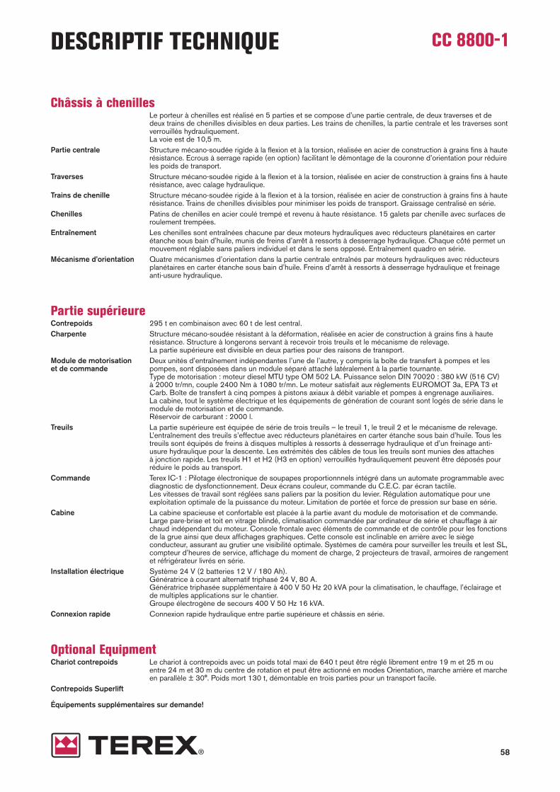
58
CC 8800-1DESCRIPTIF TECHNIQUE
Châssis à chenillesLe porteur à chenilles est réalisé en 5 parties et se compose d’une partie centrale, de deux traverses et dedeux trains de chenilles divisibles en deux parties. Les trains de chenilles, la partie centrale et les traverses sontverrouillés hydrauliquement. La voie est de 10,5 m.
Partie centrale Structure mécano-soudée rigide à la flexion et à la torsion, réalisée en acier de construction à grains fins à haute résistance. Ecrous à serrage rapide (en option) facilitant le démontage de la couronne d’orien tation pour réduireles poids de transport.
Traverses Structure mécano-soudée rigide à la flexion et à la torsion, réalisée en acier de construction à grains fins à haute résistance, avec calage hydraulique.
Trains de chenille Structure mécano-soudée rigide à la flexion et à la torsion, réalisée en acier de construction à grains fins à haute résistance. Trains de chenilles divisibles pour minimiser les poids de transport. Graissage centralisé en série.
Chenilles Patins de chenilles en acier coulé trempé et revenu à haute résistance. 15 galets par chenille avec surfaces deroulement trempées.
Entraînement Les chenilles sont entraînées chacune par deux moteurs hydrauliques avec réducteurs planétaires en carterétanche sous bain d’huile, munis de freins d’arrêt à ressorts à desserrage hydraulique. Chaque côté permet unmouvement réglable sans paliers individuel et dans le sens opposé. Entraînement quadro en série.
Mécanisme d’orientation Quatre mécanismes d’orientation dans la partie centrale entraînés par moteurs hydrauliques avec réducteursplanétaires en carter étanche sous bain d’huile. Freins d’arrêt à ressorts à desserrage hydraulique et freinageanti-usure hydraulique.
Partie supérieureContrepoids 295 t en combinaison avec 60 t de lest central.Charpente Structure mécano-soudée résistant à la déformation, réalisée en acier de construction à grains fins à haute
résistance. Structure à longerons servant à recevoir trois treuils et le mécanisme de relevage. La partie supérieure est divisible en deux parties pour des raisons de transport.
Module de motorisation Deux unités d’entraînement indépendantes l’une de l’autre, y compris la boîte de transfert à pompes et les et de commande pompes, sont disposées dans un module séparé attaché latéralement à la partie tournante.
Type de motorisation : moteur diesel MTU type OM 502 LA. Puissance selon DIN 70020 : 380 kW (516 CV)à 2000 tr/mn, couple 2400 Nm à 1080 tr/mn. Le moteur satisfait aux réglements EUROMOT 3a, EPA T3 etCarb. Boîte de transfert à cinq pompes à pistons axiaux à débit variable et pompes à engrenage auxili aires. La cabine, tout le système électrique et les équipements de génération de courant sont logés de série dans lemodule de motorisation et de commande.Réservoir de carburant : 2000 l.
Treuils La partie supérieure est équipée de série de trois treuils – le treuil 1, le treuil 2 et le mécanisme de relevage.L’entraînement des treuils s’effectue avec réducteurs planétaires en carter étanche sous bain d’huile. Tous lestreuils sont équipés de freins à disques multiples à ressorts à desserrage hydraulique et d’un freinage anti-usure hydraulique pour la descente. Les extrémités des câbles de tous les treuils sont munies des attachesà jonction rapide. Les treuils H1 et H2 (H3 en option) verrouillés hydrauliquement peuvent être déposés pour réduire le poids au transport.
Commande Terex IC-1 : Pilotage électronique de soupapes proportionnnels intégré dans un automate program mable avecdiagnostic de dysfonctionnement. Deux écrans couleur, commande du C.E.C. par écran tactile. Les vitesses de travail sont réglées sans paliers par la position du levier. Régulation automatique pour une exploitation optimale de la puissance du moteur. Limitation de portée et force de pression sur base en série.
Cabine La cabine spacieuse et confortable est placée à la partie avant du module de motorisation et de com mande.Large pare-brise et toit en vitrage blindé, climatisation commandée par ordinateur de série et chauffage à airchaud indépendant du moteur. Console frontale avec éléments de commande et de contrôle pour les fonctionsde la grue ainsi que deux affichages graphiques. Cette console est inclinable en arrière avec le siège conducteur, assurant au grutier une visibilité optimale. Systèmes de caméra pour surveiller les treuils et lest SL,compteur d’heures de service, affichage du moment de charge, 2 projecteurs de travail, armoires de rangementet réfrigérateur livrés en série.
Installation électrique Système 24 V (2 batteries 12 V / 180 Ah).Génératrice à courant alternatif triphasé 24 V, 80 A.Génératrice triphasée supplémentaire à 400 V 50 Hz 20 kVA pour la climatisation, le chauffage, l’éclairage etde multiples applications sur le chantier. Groupe électrogène de secours 400 V 50 Hz 16 kVA.
Connexion rapide Connexion rapide hydraulique entre partie supérieure et châssis en série.
Optional EquipmentChariot contrepoids Le chariot à contrepoids avec un poids total maxi de 640 t peut être réglé librement entre 19 m et 25 m ou
entre 24 m et 30 m du centre de rotation et peut être actionné en modes Orientation, marche arrière et marcheen parallèle ± 30°. Poids mort 130 t, démontable en trois parties pour un transport facile.
Contrepoids Superlift
Équipements supplémentaires sur demande!

59
CC 8800-1DESCRIPTIF TECHNIQUE
Combinaisons de flècheGénéral Construction tubulaire treillie en acier de haute résistance à grains fins. Passerelles sur flèche principale,
volée variable et mât superlift. Verrouillage hydraulique.SSL Flèche principale : pied 10 m, tronçons 6 m et 12 m, tête de flèche 2 m avec 2 jeux de poulies.
Equipement Superlift.Longueurs de flèche principale : 54-108 m
HSSL Flèche principale : Avec utilisation des composants lourds de la flèche principale.Equipement Superlift.Longueurs de flèche principale : 48-84 m.
SSL / LSL (SGL 108 m) Flèche principale : pied 10 m, tronçons 6 m et 12 m, allongée de tronçons de fléchette 6 m et 12 m, tête pourcharges lourdes 2 m avec 1 jeu de poulie de flèche principale SSL.Equipement Superlift.Longueurs de flèche principale : 114-156 m
SWSL Flèche principale : idem SSL. Inclinaison 88° à 45°Fléchette à volée variable : pied 10 m, tronçons 6 m et 12 m, tête pour charges lourdes 2 m avec 1 jeu de poulie de flèche principale SSL.Equipement Superlift.Longueurs de flèche principale : 54-108 mLongueurs de volée variable : 36-108 m
SFSL Idem SWSL. Inclinaison de fléchette : 15°.
SFVL Flèche principale : idem SSL.Fléchette fixe : pied 10 m, tête pour charges lourdes 2 m avec 2 jeux de poulies de flèche principale SSL.Equipement Superlift.Longueurs de flèche principale : 54-108 mLongueur de volée variable : 12 mInclinaison : 15°.
Boulonnement de flèche Boulonnement hydraulique des intercalaires de flèche en série.Tambour de mouflage Monté sur la partie supérieure en série.Sécurités Contrôleur d’état de charge électronique, contacteur de fin de course haut, limiteurs de mouvements de la
flèche, retenues hydrauliques anti-basculement de la flèche, anémomètre.
Combinaisons SuperliftTele-SL Mât 50 m (type 2621), panier du contrepoids 640 t ou chariot contrepoids en option avec max. 640 t.
Rayon du Superlift variable de 19 m à 25 m pour un rayon de mât 22 m et de 24 m à 30 m de pour un rayonde mât 26,4 m.
Equipements optionnelsEquipement potence Pour 2 lignes, montées sur flèche principale ou têtes de fléchette.3 m – 70 t Distance au jeu de poulies avec la flèche en position relevée env. 1,3 m.
Capacité de levage : max. 70 t.Treuil H3 Monté sur la partie supérieure.Système anti-incendie Système anti-incendie automatique avec clapets coupe-feu automatiques sur conteneur.Système de détection Détection uniquement.d’incendieLit superposé dans la cabine Lit superposé rabattable.Sièges pliant dans la cabine 2 sièges pliant dans la cabine.Protection antichute Pour flèche principale, volée variable et mât SL.

CC 8800-1
www.terexcranes.comEffective Date: July 2010.Product specifications and prices are subject to change without notice or obligation. The photographs and/or drawings in this document are for illustrativepurposes only. Refer to the appropriate Operator’s Manual for instructions on the proper use of this equipment. Failure to follow the appropriate Operator’sManual when using our equipment or to otherwise act irresponsibly may result in serious injury or death. The only warranty applicable to our equipment isthe standard written warranty applicable to the particular product and sale and Terex makes no other warranty, express or implied. Products and services listed may be trademarks, service marks or trade-names of Terex Corporation and/or its subsidiaries in the USA and other countries. All rights are reserved. Terex® is a registered trademark of Terex Corporation in the USA and many other countries.
Gültig ab: Juli 2010.Produktbeschreibungen und Preise können jederzeit und ohne Verpflichtung zur Ankün digung geändert werden. Die in diesem Dokument enthaltenenFotos und/oder Zeichnungen dienen rein anschau lichen Zwecken. Anweisungen zur ordnungsgemäßen Verwendung dieser Aus rüstung entnehmen Siebitte dem zugehörigen Betriebshandbuch. Nicht befolgung des Betriebshandbuchs bei der Verwendung unserer Produkte oder anderweitig fahrlässigesVerhalten kann zu schwerwiegenden Verletzungen oder Tod führen. Für dieses Produkt wird ausschließlich die entsprechende, schriftlich niedergelegteStandardgarantie gewährt. Terex leistet keinerlei darüber hinaus gehende Garantie, weder ausdrücklich noch stillschweigend. Die Bezeichnungen der aufgeführten Produkte und Leistungen sind gegebenenfalls Marken, Service marken oder Han dels namen der Terex Corporation und/oder ihrer Tochter-gesellschaften in den USA und anderen Ländern. Alle Rechte vorbehalten. „TEREX“ ist eine eingetragene Marke der Terex Corporation in den USA und vielen anderen Ländern.
Date d’effet : Juillet 2010.Les spécifications et prix des produits sont sujets à modification sans avis ou obligation. Les photographies et/ou dessins contenus dans ce documentssont uniquement pour illustration. Veuillez vous référer à la notice d’utili sation appropriée pour les instructions quant à l’utilisation correcte de cet équipement. Tout manquement au suivi de la notice d’utilisation appropriée lors de l’utilisation de notre équipement ou tout acte autrement irresponsablepeut résulter en blessure corporelle sérieuse ou mortelle La seule garantie applicable à notre équipement est la garantie standard écrite applicable à unproduit et à une vente spécifique. Terex n’offre aucune autre garantie, expresse ou explicite. Les produis et services proposés peuvent être des marquesde fabrique, des marques de service ou des appellations commerciales de Terex Corporation et/ou ses filiales aux Etats Unis et dans les autres pays,et tous les droits sont réservés. «TEREX» est une marque déposée de Terex Corporation aux Etats Unis et dans de nombreux autres pays.
Copyright 2010 Terex Corporation
Terex Cranes, Global Marketing, Dinglerstraße 24, 66482 Zweibrücken, GermanyTel. +49 (0) 6332 830, Email: [email protected], www.terexcranes.com
Brochure Reference: TC-DS-M-E/F/G-CC 8800-1-07/10


![Home Page []0.7000 max 35 min 65 max 85 max 125 max 1 50 max I .5 max I max NO 1 STRIP 75 max 25 min 0.03 max 15 max 40 max Specific Gravity @ 150C Distillation:](https://img.pdfslide.net/doc/110x75/5f201a8f5d3b4e45a5210259/home-page-07000-max-35-min-65-max-85-max-125-max-1-50-max-i-5-max-i-max-no.jpg)