Embed Size (px)
Citation preview
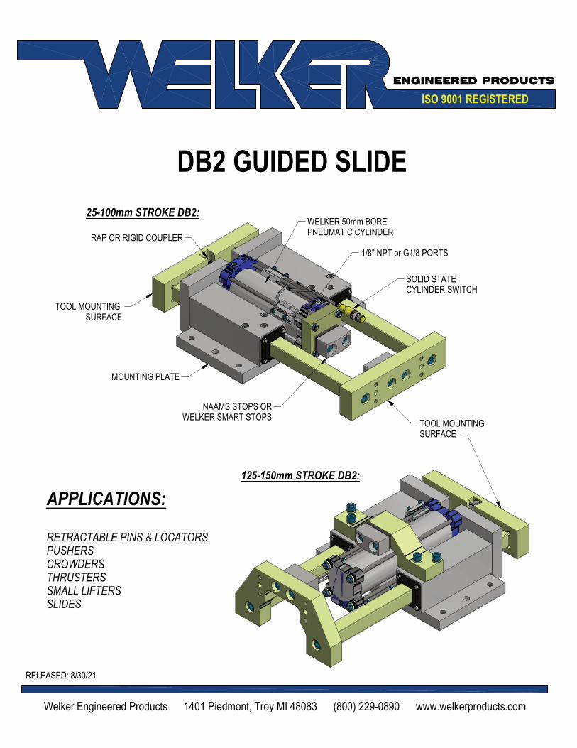
APPLICATIONS:
RETRACTABLE PINS & LOCATORS
PUSHERS
CROWDERS
THRUSTERS
SMALL LIFTERS
SLIDES
ISO 9001 REGISTERED
ENGINEERED PRODUCTS
DB2 GUIDED SLIDE
RELEASED: 8/30/21
Welker Engineered Products 1401 Piedmont, Troy MI 48083 (800) 229-0890 www.welkerproducts.com
RAP OR RIGID COUPLER
TOOL MOUNTING SURFACE
MOUNTING PLATE
TOOL MOUNTINGSURFACE
NAAMS STOPS ORWELKER SMART STOPS
SOLID STATECYLINDER SWITCH
WELKER 50mm BOREPNEUMATIC CYLINDER
1/8" NPT or G1/8 PORTS
25-100mm STROKE DB2:
125-150mm STROKE DB2:

D B 2 X X X X
Stroke075 25-150mm
(in 25mm increments)
CouplerA Rap (shortens nominal stroke by 2mm)B Rigid
Actuator01 Pneumatic - Single Rod - NPT02 Pneumatic - Single Rod - G Port
Switch00 No switch
LX See Welker Cylinder Switch ChartP1 Welker Smart Stops
SEE SHIM CHART BELOW
Additional Retract Shims ~ Whole mm
Additional Retract Shims ~ Quarter mm
Additional Extend Shims ~ Whole mm
Additional Extend Shims ~ Quarter mm
Switch Part Number Manufacturer Description
L3
SWITCH L3*
L3 sw itch is w eld f ield immune, comparable to
World Sw itches. Dual sensor sw itch, 1 per cylinder
Welker4-Wire, 4-Pin, DC (PNP)
M12 X 1 Quick Disconnect
L5MK5113
Single sensor sw itch, 2 sw itches per cylinderifm Efector
3-Wire, 4-Pin, DC (NPN)
M12 X 1 Quick Disconnect
Cyli
nd
er
Sw
itch
es
Standard Switch Option - All other options may affect price and delivery
*Note that some mid and low frequency DC resistance applications (i.e. aluminum resistance w elding applications)
may cause a fault. In these applications, it is recommended that the sensor be ignored/bypassed during the w elding
cycle.
THK (mm) CODE THK (mm) CODE THK (mm) CODE THK (mm) CODE THK (mm) CODE
0 0 8 8 16 G 24 R 0.00 0
1 1 9 9 17 H 25 S 0.25 A
2 2 10 A 18 J 26 T 0.50 B
3 3 11 B 19 K 27 U 0.75 C
4 4 12 C 20 L 28 V
5 5 13 D 21 M 29 W
6 6 14 E 22 N 30 X
7 7 15 F 23 P 35 Y
SHIM CHARTQUARTER MM CODESWHOLE MILLIMETER CODES
ENGINEERED PRODUCTS
(800) 229-0890 www.welkerproducts.com
(DO NOT SCALE DRAWING)
SHEET 2
ORDERING INFORMATIONNOTE: ALL BOXES MUST BE FILLED IN FOR A COMPLETE PART NUMBER

ENGINEERED PRODUCTS
(800) 229-0890 www.welkerproducts.com
(DO NOT SCALE DRAWING)
SHEET 3
GENERAL DIMENSIONS: 25 to 100mm STROKES
WELKER DBWEB PAGE260 CENT
18
SOLID STATECYLINDER SWITCH
2X 1/8 NPT OR G PORT
50mm BORE CYLINDER
EXTENDED SHIMS
RETRACT SHIMS
25
25
2X WELKER SMART STOPSOR NAAMS STOPS
200 CENT
REMOVE STOP FORADDITIONAL STROKE
246FOR 25-50STROKE
296
FOR 75-100STROKE(SHOWN)
100.00CENT 321
FOR 25-50STROKE
421
FOR 75-100STROKE(SHOWN)
100 STROKE OPTION
75 STROKESHOWN
235.00 CENT
150.0
30.00CENT 96.00
CENT
44
91
50.8CENT
50.8CENT
M8x1.25 TAP THRU(4) HOLES NEARSIDE
(4) HOLES FARSIDEIN LINE
n8.0 P.F. THRU
(2) HOLES NEARSIDE(2) HOLES FARSIDEIN LINE
Ø10.0 S.F. THRU(2) PLACES
M10x1.5 TAP THRU(4) PLACES
DB2 UNIT WEIGHTS
STROKE: 25mm 50mm 75mm 100mm 125mm 150mm
WEIGHT: 30 lbs 28.5 lbs 33 lbs 31.5 lbs 36 lbs 34.5 lbs

ENGINEERED PRODUCTS
(800) 229-0890 www.welkerproducts.com
(DO NOT SCALE DRAWING)
SHEET 4
GENERAL DIMENSIONS: 125 & 150mm STROKES
1/8 NPT OR G PORTFARSIDE
1/8 NPT OR G PORTFARSIDE
50mm BORE CYLINDER
200 CENT
REMOVE STOP FOR ADDITIONAL STROKE 25
246
421
150STROKEOPTION
125STROKESHOWN
PORTS FACE MOUNTING SURFACE
120CENT
n8.0 P.F.THRU
(2) PLACES
M8x1.25 TAP THRU
(4) PLACES
30.00CENT
96.00CENT
94.0121
DB2 UNIT WEIGHTS
STROKE: 25mm 50mm 75mm 100mm 125mm 150mm
WEIGHT: 30 lbs 28.5 lbs 33 lbs 31.5 lbs 36 lbs 34.5 lbs
General Specifications
Switching function Normal ly Open (NO)
Output type PNP
Rated operating dis tance,s n 1.75mm
Output polari ty DC
Ass ured operating dis tance s a 0 - 1.42 mm
Output type 3-wire
Nominal Ratings
Operating vol tage, UB 5 - 30 V DC
Switching frequency, f 0 - 6000 Hz
Revers e polari ty protection Revers e polari ty protected
Short-ci rcui t protection Puls ing
Voltage drop, Ud ≤ 1.5 V
Operating current, IL 0 - 100 mA
Off-state current, I r 0 - 0.2 mA
No-load supply current, I0 ≤ 15 mA
Indicators/Operating Means
Operating vol tage indicator LED green
Switching state indicator LED yel low
Ambient Conditions
Ambient temperature -40 - 85 °C (-40 - 185 °F)
Storage temperature -40 - 85 °C (-40 - 185 °F)
Mechanical Specifications
Connection type Connector plug M12 x 1 , 4-pin
Cable length 255mm
Degree of protection IP67
Cable materia l Weld spatter res is tant, robotic qua l i ty POC
Cable color Orange ENGINEERED PRODUCTS
(800) 229-0890 www.welkerproducts.com
(DO NOT SCALE DRAWING)
SHEET 5
1 4
32
LOAD
BRN
BLK
BLU
WIRING DIAGRAM (PNP)
+
-
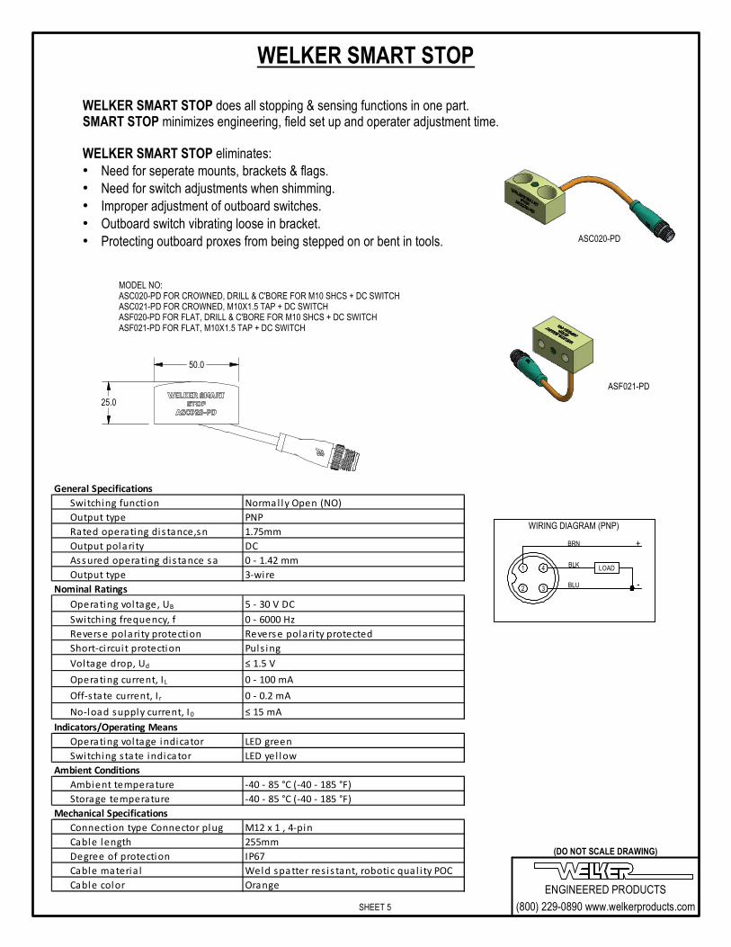
WELKER SMART STOP
WELKER SMART STOP does all stopping & sensing functions in one part.SMART STOP minimizes engineering, field set up and operater adjustment time. WELKER SMART STOP eliminates:
• Need for seperate mounts, brackets & flags.
• Need for switch adjustments when shimming.
• Improper adjustment of outboard switches.
• Outboard switch vibrating loose in bracket.
• Protecting outboard proxes from being stepped on or bent in tools. ASC020-PD
ASF021-PD
MODEL NO:ASC020-PD FOR CROWNED, DRILL & C'BORE FOR M10 SHCS + DC SWITCHASC021-PD FOR CROWNED, M10X1.5 TAP + DC SWITCHASF020-PD FOR FLAT, DRILL & C'BORE FOR M10 SHCS + DC SWITCHASF021-PD FOR FLAT, M10X1.5 TAP + DC SWITCH
25.0
50.0

ENGINEERED PRODUCTS
(800) 229-0890 www.welkerproducts.com
(DO NOT SCALE DRAWING)
SHEET 6
±0.13 (±.005") MAXDEFLECTION AT END OF RAMUP TO 100mm STROKE
Wipers: The wiper is a custom molded moly impregnated urethane wiper. Welker recommends changing the wiper yearly. Specific applications may require more or less frequent wiper service. Stroke: The stroke accuracy is limited to that of the cylinder. Normal cylinder stroke accuracy is ± .015" (0.38mm). Rap couplings cause the unit to be 2mm less than the nominal stroke of the cylinder. The rap allows the cylinder to accelerate without load, acting like a slide hammer. The impact of the coupler helps freetooling from a bound condition, similar to a dowel puller. Welker cylinders do not require lubrication. Switch: DB2 is available with solid state cylinder switch or Welker Smart Stop. Repeatability: Unit utilizes a full contact bearing surface for high repeatability. Repeatability within ±.002" (0.05mm) part to part is achievable. Wear: Defined as variance in position under load over time. Shot pin tests indicate maximum wear of .002" wear at 3 million cycles. Loading and Deflection: Maximum deflection is ±.005" and is measured at the end of the ram up to the specified strokes and up to the loads and distances as shown below. Longer extensions can be used at lower tolerances and loads. Tooling mounted closer to the body exhibit less deflection. For applications with longer strokes and higher loads, consult Welker.
Welker DB2 Technical Information
MOUNTED TOOLING MUST BE WITHIN APPROVED APPLICATION RADIUS FROM END OF RAM:50 lbf @ R = 100.0mm (4.0")
R100.0 TYP.
q
170 170
150