Embed Size (px)
Citation preview
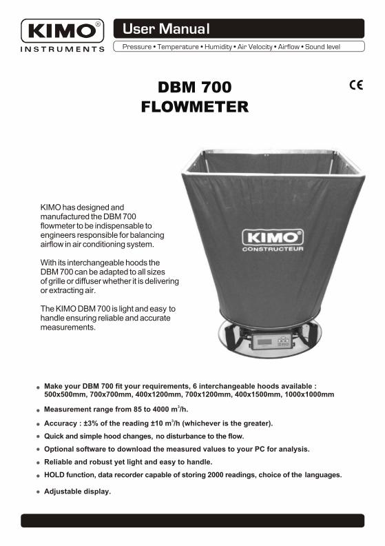
DBM 700
FLOWMETER
KIMO has designed andmanufactured the DBM 700flowmeter to be indispensable toengineers responsible for balancingairflow in air conditioning system.
With its interchangeable hoods theDBM 700 can be adapted to all sizesof grille or diffuser whether it is deliveringor extracting air.
The KIMO DBM 700 is light and easy tohandle ensuring reliable and accuratemeasurements.
3Measurement range from 85 to 4000 m /h.
3Accuracy : ±3% of the reading ±10 m /h (whichever is the greater).
Quick and simple hood changes, no disturbance to the flow.
Reliable and robust yet light and easy to handle.
HOLD function, data recorder capable of storing 2000 readings, choice of the languages.
Adjustable display.
Make your DBM 700 fit your requirements, 6 interchangeable hoods available :500x500mm, 700x700mm, 400x1200mm, 700x1200mm, 400x1500mm, 1000x1000mm
Optional software to download the measured values to your PC for analysis.
User ManualPressure • Temperature • Humidity • Air Velocity • Airflow • Sound level

TECHNICAL SPECIFICATIONS
HOODS ASSEMBLY
OPERATION
MAINTENANCE
CALIBRATION
.....................................................................4-5-6
..........................................................................7
......................................................................7
..............................................................2-3
...........................................1
SUMMARY

TECHNICAL SPECIFICATION
1
DIMENSIONS : 700 x 700 hood height 860 mmHeight of the base : 160 mm
WEIGHT : Base only :1,8 kg
Base + hood : 2,5 kg
BASE DIAMETER : 500 mm external - 400 mm internal.
500 x 500 mm, 700 x 700 mm, 400 x 1200 mm,700 X 1200 mm, 400 x 1500 mm, 1000 x 1000 mm.
DISPLAY : Alphanumeric. 4 lines of 16 characters.
HOODS DIMENSIONS :
MEASUREMENT RANGE ACCURACY RESOLUTION
AIR FLOW
TEMPERATURE
3from 85 to 4000 m /h
0 to 50°C
33% of the measurement ±10 m /h3 31 m /h from 0 to 1000 m /h
3 310 m /h from 1000 to 4000 m /h
0,1°C2% of the measurement ±0,1°C
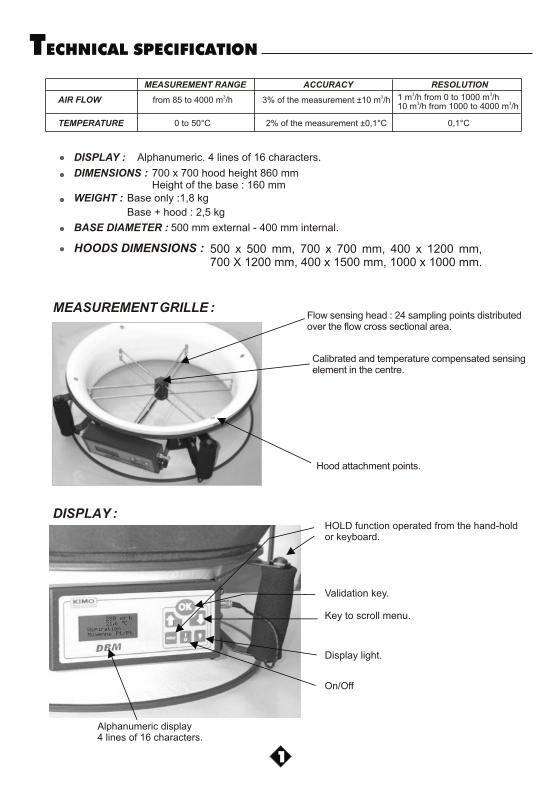
DISPLAY :
Alphanumeric display4 lines of 16 characters.
Display light.
On/Off
HOLD function operated from the hand-holdor keyboard.
Key to scroll menu.
MEASUREMENT GRILLE :
Validation key.
Calibrated and temperature compensated sensingelement in the centre.
Aspiration
Moyenne Pt/Pt
3
280 m/ h
21.6 °C
Flow sensing head : 24 sampling points distributedover the flow cross sectional area.
Hood attachment points.
2
HOODS ASSEMBLY
500 x 500 mm, 700 x 700 mm, 400 x 1200 mm,700 X 1200 mm, 400 x 1500 mm, 1000 x 1000 mm.
6 SIZES AVAILABLE :
Assemble the aluminium sections, tighten the knurled fasteners. Put the foam uppermost.
1.
Select the correct hood for the frame.2.
Put the elastic (located at the bottom of the hood) other the instrument taking care to align the seams with the hood attachment points.
3.Put the elastic (located at the top of the hood) over the frame ensuring that the seams are in the corners.
4.
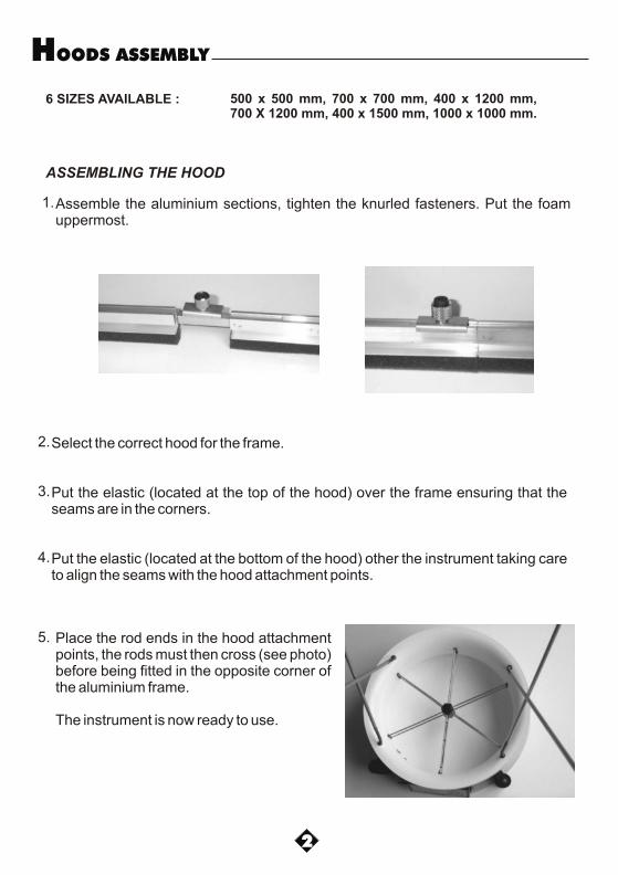
Place the rod ends in the hood attachment points, the rods must then cross (see photo) before being fitted in the opposite corner of the aluminium frame.
The instrument is now ready to use.
5.
ASSEMBLING THE HOOD
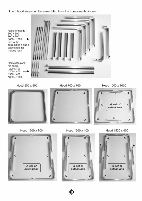
The 6 hood sizes can be assembled from the components shown :
3
Hood 500 x 500 Hood 1000 x 1000Hood 700 x 700
Hood 1200 x 700 Hood 1500 x 400Hood 1200 x 400
Rod extensionsfor hoods1200 x 7001200 x 4001500 x 4001000 x 1000
Rods for hoods :500 x 500700 x 7001000 x 1000Screw theextremities a and beachothers formaking rods.
C
B
D
A
a
b
AA
AA
AA
AA
B
B
AA
AA
CC
DA
DA
CC
DA
DA
CC
B B
B BA set of extensions
A set of extensions
A set of extensions
A set of extensions
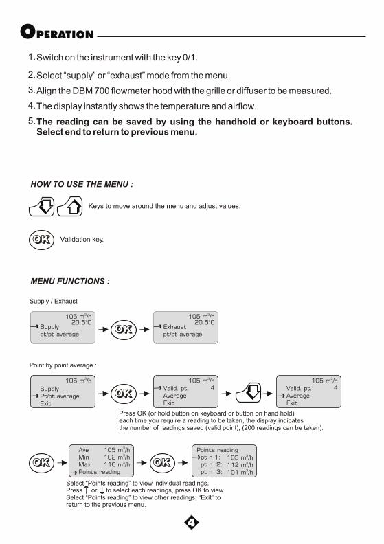
OPERATION
Switch on the instrument with the key 0/1.1.
2.Select “supply” or “exhaust” mode from the menu.
3.Align the DBM 700 flowmeter hood with the grille or diffuser to be measured.
4.The display instantly shows the temperature and airflow.
5.The reading can be saved by using the handhold or keyboard buttons. Select end to return to previous menu.
MENU FUNCTIONS :
Supplypt/pt average
3105 m /h20.5°C
OKOKOK
Press OK (or hold button on keyboard or button on hand hold)each time you require a reading to be taken, the display indicatesthe number of readings saved (valid point), (200 readings can be taken).
Exhaustpt/pt average
3105 m /h20.5°C
Supply / Exhaust
SupplyPt/pt averageExit
3105 m /h
OKOKOKValid. pt.AverageExit
3105 m /h4
Point by point average :
HOW TO USE THE MENU :
OKOKOK Validation key.
Keys to move around the menu and adjust values.
Valid. pt.AverageExit
3105 m /h4
AveMinMaxPoints reading
3105 m /h3
102 m /h3110 m /h
Select “Points reading” to view individual readings.Press or to select each readings, press OK to view.Select “Points reading” to view other readings, “Exit” to return to the previous menu.
OKOKOK
Points reading pt n 1: pt n 2: pt n 3:
3105 m /h3
112 m /h3101 m /h
4
OKOKOK
Average pt/ptC.F. 0.002
3105 m /h20.5°C
C.Fact (x1000)
3105 m /h
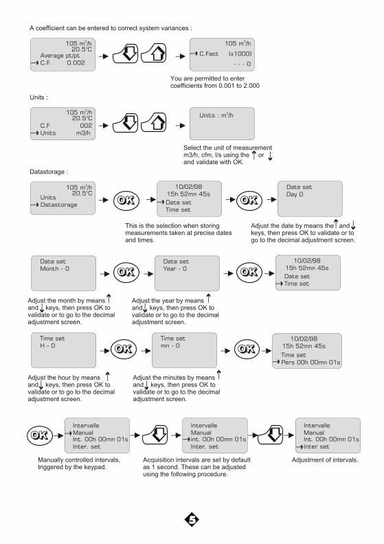
A coefficient can be entered to correct system variances :
You are permitted to entercoefficients from 0.001 to 2.000
C.F 002Units m3/h
3Units : m /h
Units :
Select the unit of measurementm3/h, cfm, l/s using the orand validate with OK.
UnitsDatastorage
Datastorage :
OKOKOK Date setTime set
10/02/9815h 52mn 45s
This is the selection when storingmeasurements taken at precise datesand times.
Date setDay 0
Adjust the date by means the andkeys, then press OK to validate or togo to the decimal adjustment screen.
Date setMonth - 0
Adjust the month by meansand keys, then press OK tovalidate or to go to the decimaladjustment screen.
Date setYear - 0
Adjust the year by meansand keys, then press OK tovalidate or to go to the decimaladjustment screen.
Date setTime set
10/02/9815h 52mn 45s
Time setH - 0
Adjust the hour by meansand keys, then press OK tovalidate or to go to the decimaladjustment screen.
Time setmn - 0
Adjust the minutes by meansand keys, then press OK tovalidate or to go to the decimaladjustment screen.
Time setPers 00h 00mn 01s
10/02/9815h 52mn 45s
5
OKOKOK
OKOKOKOKOKOK
OKOKOKOKOKOK
Int. 00h 00mn 01sInter. set
IntervalleManual
Manually controlled intervals,triggered by the keypad.
int. 00h 00mn 01sInter. set
IntervalleManual
Int. 00h 00mn 01sInter set
IntervalleManual
Acquisition intervals are set by defaultas 1 second. These can be adjustedusing the following procedure.
Adjustment of intervals.
- - - 0
OKOKOK
3105 m /h20.5°C
3105 m /h20.5°C
6
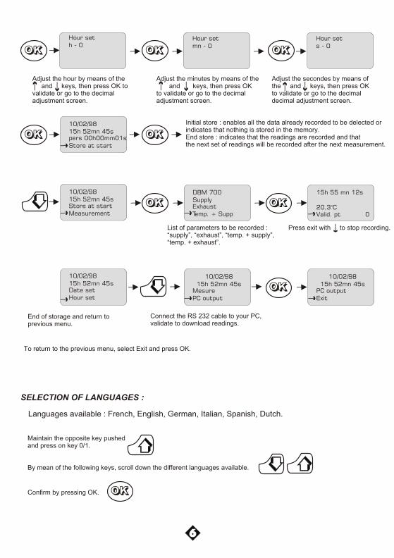
Hour seth - 0
Adjust the hour by means of the and keys, then press OK to validate or go to the decimaladjustment screen.
Hour setmn - 0
Adjust the minutes by means of the and keys, then press OKto validate or go to the decimaladjustment screen.
Hour sets - 0
Adjust the secondes by means ofthe and keys, then press OKto validate or go to the decimaldecimal adjustment screen.
pers 00h00mm01sStore at start
10/02/9815h 52mn 45s
Initial store : enables all the data already recorded to be delected orindicates that nothing is stored in the memory.End store : indicates that the readings are recorded and thatthe next set of readings will be recorded after the next measurement.
Store at startMeasurement
10/02/9815h 52mn 45s
ExhaustTemp. + Supp
DBM 700Supply
Valid. pt 0
15h 55 mn 12s
20,3°C
End of storage and return toprevious menu.
MesurePC output
10/02/9815h 52mn 45s
Connect the RS 232 cable to your PC,validate to download readings.
PC outputExit
10/02/9815h 52mn 45s
To return to the previous menu, select Exit and press OK.
Press exit with to stop recording.
Date setHour set
10/02/9815h 52mn 45s
List of parameters to be recorded :“supply”, “exhaust”, “temp. + supply”,“temp. + exhaust”.
OKOKOK OKOKOK OKOKOK
OKOKOK OKOKOK
OKOKOK OKOKOK
OKOKOK
SELECTION OF LANGUAGES :
Languages available : French, English, German, Italian, Spanish, Dutch.
Maintain the opposite key pushed and press on key 0/1.
By mean of the following keys, scroll down the different languages available.
Confirm by pressing OK. OKOKOK
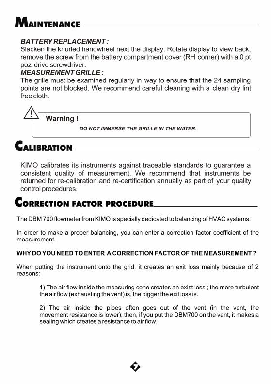
BATTERY REPLACEMENT :Slacken the knurled handwheel next the display. Rotate display to view back, remove the screw from the battery compartment cover (RH corner) with a 0 pt pozi drive screwdriver.MEASUREMENT GRILLE :The grille must be examined regularly in way to ensure that the 24 sampling points are not blocked. We recommend careful cleaning with a clean dry lint free cloth.
MAINTENANCE
KIMO calibrates its instruments against traceable standards to guarantee a consistent quality of measurement. We recommend that instruments be returned for re-calibration and re-certification annually as part of your quality control procedures.
CALIBRATION
7
DO NOT IMMERSE THE GRILLE IN THE WATER.
Warning !!
The DBM 700 flowmeter from KIMO is specially dedicated to balancing of HVAC systems.
In order to make a proper balancing, you can enter a correction factor coefficient of the measurement.
WHY DO YOU NEED TO ENTER A CORRECTION FACTOR OF THE MEASUREMENT ?
When putting the instrument onto the grid, it creates an exit loss mainly because of 2 reasons:
1) The air flow inside the measuring cone creates an exist loss ; the more turbulent the air flow (exhausting the vent) is, the bigger the exit loss is.
2) The air inside the pipes often goes out of the vent (in the vent, the movement resistance is lower); then, if you put the DBM700 on the vent, it makes a sealing which creates a resistance to air flow.
CORRECTION FACTOR PROCEDURE
Re
f. N
T a
ng
- D
BM
70
0 -
08
/08
E
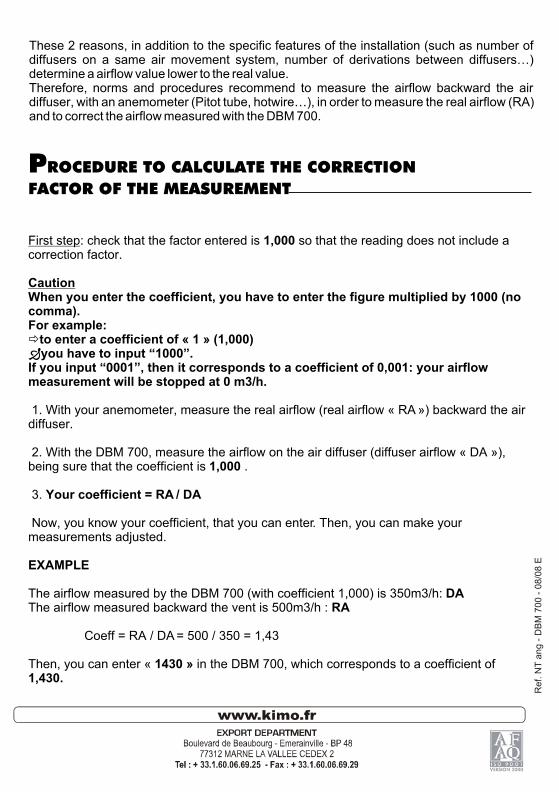
These 2 reasons, in addition to the specific features of the installation (such as number of diffusers on a same air movement system, number of derivations between diffusers…) determine a airflow value lower to the real value.Therefore, norms and procedures recommend to measure the airflow backward the air diffuser, with an anemometer (Pitot tube, hotwire…), in order to measure the real airflow (RA) and to correct the airflow measured with the DBM 700.
PROCEDURE TO CALCULATE THE CORRECTION
FACTOR OF THE MEASUREMENT
First step: check that the factor entered is 1,000 so that the reading does not include a correction factor.
CautionWhen you enter the coefficient, you have to enter the figure multiplied by 1000 (no comma).For example: ðto enter a coefficient of « 1 » (1,000)Ðyou have to input “1000”.If you input “0001”, then it corresponds to a coefficient of 0,001: your airflow measurement will be stopped at 0 m3/h.
1. With your anemometer, measure the real airflow (real airflow « RA ») backward the air diffuser.
2. With the DBM 700, measure the airflow on the air diffuser (diffuser airflow « DA »), being sure that the coefficient is 1,000 .
3. Your coefficient = RA / DA
Now, you know your coefficient, that you can enter. Then, you can make your measurements adjusted.
EXAMPLE
The airflow measured by the DBM 700 (with coefficient 1,000) is 350m3/h: DAThe airflow measured backward the vent is 500m3/h : RA
Coeff = RA / DA = 500 / 350 = 1,43
Then, you can enter « 1430 » in the DBM 700, which corresponds to a coefficient of 1,430.