Embed Size (px)
Citation preview
�
DBM - CAN
Application Manual
GB-4536 - Dec/00

1
Introduction
This manual provides the necessary information for an effective use of DBM CAN Bus.It must be used in conjunction with the "DBM 04 Installation Manual" and the "DBM 04User's Manual".
This manual includes:
• Description• Hardware differences between DBM-CAN and DBM 04 drive• Software configuration• Network management• Emergency• Objects
The following version, software code and checksums apply:
VERSION: V01.01CODE: SW1067EPROM DSP: LO: 8E56
HI: 9F42EPROM 8031: 2FCOEPROM C515: 5D35

2
Section 1 - Description
CAN is a serial bus system with multi-master capabilities, that is, all CAN nodes areable to transmit data and several CAN nodes can request the bus simultaneously. Theserial bus system with real-time capabilities is the subject of the ISO 11898 internationalstandard and covers the lowest two layers of the ISO/OSI reference model. In CANnetworks there is no addressing of subscribers or stations in the conventional sense,but instead, prioritized messages are transmitted. A transmitter sends a message to allCAN nodes (broadcasting). Each node decides on the basis of the identifier receivedwhether it should process the message or not. The identifier also determines the prioritythat the message enjoys in competition for bus access.Open fieldbus systems enable the construction of machines by connecting componentsfrom multiple vendors while minimizing the effort required for interfacing. To achieve anopen networking system, it is necessary to standardize the various layers ofcommunication used.
CANopen uses the international CAN standard, ISO 11898 as the basis forcommunication. This standard covers the lower two layers of communication specifiedby the OSI model. Building on this, the CANopen profile family specifies standardizedcommunication mechanisms and device functionality for CAN-based systems. Theprofile family wich is available and maintained by CAN in Automation (CiA) consists ofthe application layer and communication profile (DS 301), various frameworks andrecommendations (CiA DS-30x) and various device profiles (CiA DS-40x).

3
Section 2 - Hardware differences between DBM-CAN andDBM 04
Tab. 2.1 – J1A Connector - Sub-D 9 pos. - CA NBUS SignalsPanel side: maleWiring side: female with conductive shell
Pos. Name1 BUS_H BUS High signal
2 BUS_H BUS High signal
3 0V Digital 0V
4 - N.C.5 - N.C.6 0V Digital 0V
7 BUS_L BUS Low signal
8 BUS_L BUS Low signal
9 +5V +5Vdc output

4
Section 3 – Software Configuration
AS - Node Show
Function: it allows display of the node identification, if unknown. Toavoid simultaneous answers on the line from more than onemodule, it is necessary that serial flat J2 is connected only between
power supply and the questioned module. It is different fromSA command, which is used to change node identification.
Syntax: data monitoring: � ∗ AS <CR>Address type: -Unit of measure: -Range: -Default: -Password: no(∗) addressing: compulsoryOpposite to: -See also: SA

5
SA - Selection of the node identification.
Function: it is used to assign the module node identification different fromdefault. A module programmed as "node 1" willautomatically assign, for the other axes, the following nodes, i.e.
2 - 3 (if triple-axis) or 2 (if double-axis).Syntax: data input: � node SA n <CR>Address type: axisUnit of measure: -Range: 1 to 99Default: 1Password: no(∗) addressing: noOpposite to: -See also: AS
REMARK: To perform SA command, only one module at the time must be connectedto J2 flat cable.

6
Section 4 – Network Management
The network management supports a simplified start of the network and can beexpanded modular according to system demand.
Tab.4.1 - Network Management
CAN header:Byte Bit7 Bit6 Bit5 Bit4 Bit3 Bit2 Bit1 Bit0 Hex
Byte0 0 0 0 0 0 0 0 0 00
Byte1 0 0 0 0 0 0 1 0 02
CAN data:Byte Bit7 Bit6 Bit5 Bit4 Bit3 Bit2 Bit1 Bit0 Hex
Byte2 C7 C6 C5 C4 C3 C2 C1 C0 CMD
Byte3 A7 A6 A5 A4 A3 A2 A1 A0 xx Node ID (00 => all Nodes)
Byte4
Byte5
Byte6
Byte7
Byte8
Byte9
C7 C6 C5 C4 C3 C2 C1 C0 Hex CMD0 0 0 0 0 0 0 1 01 Start0 0 0 0 0 0 1 0 02 Stop1 0 0 0 0 0 0 0 80 Pre Operational1 0 0 0 0 0 0 1 81 Reset Node1 0 0 0 0 0 1 0 82 Reset Communication Parameter

7
Section 5 – Emergency
The module status is transmitted in case of error via emergency telegrams with highpriority. these telegrams have a data length of 8 byte and contain extensive errorinformation.
Tab.5.1 Emergency
CAN header:Byte Bit7 Bit6 Bit5 Bit4 Bit3 Bit2 Bit1 Bit0 Hex
Byte0 0 0 0 1 A6 A5 A4 A3 10
Byte1 A2 A1 A0 0 0 0 0 0 00
CAN data:Byte Bit7 Bit6 Bit5 Bit4 Bit3 Bit2 Bit1 Bit0 Hex
Byte0 0 0 0 0 0 0 0 0 00 Error Code
Byte1 x x x x 0 0 0 0 x0 Error Code
Byte2 0 0 0 0 0 0 0 1 01 Error Register (Obj. 1001)
Byte3 0 0 0 0 0 0 0 0 00 Specific error register
Byte4 0 0 0 0 0 0 0 0 00 Specific error register
Byte5 0 0 0 0 0 0 0 0 00 Specific error register
Byte6 0 0 0 0 0 0 0 0 00 Specific error register
Byte7 0 0 0 0 0 0 0 0 00 Specific error register
Error Code 0000 No Error - Fault Resetted
1000 Generic Error
8000 Communication Error (SYNC absence)
8100 Communication warning reached
8140 recovered from busoff

8
Section 6 - Objects
6.1 Object Dictionary
DBM – CAN Object DictionaryOBJ Name Type Subindex Description Data PDO Mapping Axis Note
- Network management - - - - - - No all wo- Emergency - - - - - - No all ro
1000 Device type VAR Unsigned32 - - FFFF0402 SDO No all ro1001 Error register VAR Unsigned8 - - 0X SDO No all ro
Unsigned32 00 N° of PDOs supported 00030003h SDO No all roUnsigned32 01 N° synchronous PDOs 00030003h SDO No all ro1004 Number of PDOs supported ARRAYUnsigned32 02 N°asynchronous PDOs 00000000h SDO No all ro
1005 Sync VAR Unsigned32 - - - - No all ro1006 Communication Cycle Period VAR Unsigned32 - - XXXXXXXX SDO No all rw100A Manufacturer SW version VAR Unsigned32 - Version xx.xx XXXXXXXX SDO No all ro100B Node ID VAR Unsigned16 - Node ID XXXX SDO No all ro
Unsigned32 00 Largest subindex supported 01 SDO No all ro1010 Store Parameters ARRAY
Unsigned32 01 Save ALL parameters XXXXXXXX SDO No all rwUnsigned32 00 Number of element 01 SDO No all ro
1018 Identity Object RECORDUnsigned32 01 Vendor ID MOOG SDO No all roUnsigned32 00 Number of objects 0X SDO No all rwUnsigned32 01 1st object XXXXXXXX SDO No all rwUnsigned32 02 2nd object XXXXXXXX SDO No all rwUnsigned32 03 3rd object XXXXXXXX SDO No all rw
1600
Mapping ParameterRxPDO1 (Node ID)RxPDO2 (Node ID + 1)RxPDO3 (Node ID + 2)
RECORD
Unsigned32 04 4th object XXXXXXXX SDO No all rwUnsigned32 00 Number of element 02 SDO No all roUnsigned32 01 COB – ID 180h + Node ID SDO No all ro1800
TxPDO Communication ParameterTxPDO1 (Node ID)TxPDO2 (Node ID + 1)TxPDO3 (Node ID + 2)
RECORDUnsigned8 02 Transmission type XX SDO No all rw
Unsigned32 00 Number of objects 0X SDO No all rwUnsigned32 01 1st object XXXXXXXX SDO No all rwUnsigned32 02 2nd object XXXXXXXX SDO No all rwUnsigned32 03 3rd object XXXXXXXX SDO No all rw
1A00
Mapping ParameterTxPDO1 (Node ID)TxPDO2 (Node ID + 1)TxPDO3 (Node ID + 2)
RECORD
Unsigned32 04 4th object XXXXXXXX SDO No all rw

9
DBM – CAN Object Dictionary (continued)OBJ Name Type Subindex Description Data PDO Mapping Axis Note
2000 Activate / Deactivate TxPDO VAR Unsigned8 - - 0X SDO No all rw
Axis 1 (Node ID)6040 Controlword VAR Unsigned16 - - 00XX PDO & SDO1 Yes 1 rw6041 Statusword VAR Unsigned16 - - 0XXX PDO & SDO1 Yes 1 ro6042 Target velocity VAR Integer16 - - XXXX PDO & SDO1 Yes 1 rw6043 Velocity demand VAR Integer16 - - XXXX PDO & SDO1 Yes 1 ro6044 Control effort VAR Integer16 - - XXXX PDO & SDO1 Yes 1 ro
Unsigned16 00 Number of element 02 SDO1 No 1 roUnsigned16 01 velocity min amount XXXX PDO & SDO1 Yes 1 rw6046 Velocity min max amount ARRAYUnsigned16 02 velocity max amount XXXX PDO & SDO1 Yes 1 rwUnsigned16 00 Number of element 01 SDO1 No 1 ro
- 01 delta speed - - - - -6048 Velocity acceleration RECORDUnsigned16 02 delta time XXXX SDO1 No 1 rwUnsigned16 00 Number of element 01 SDO1 No 1 ro
- 01 delta speed - - - - -6049 Velocity deceleration RECORDUnsigned16 02 delta time XXXX SDO1 No 1 rw
6060 Modes of operation VAR Integer8 - - 0X SDO1 No 1 wo6061 Modes of operation display VAR Integer8 - - 0X SDO1 No 1 ro
Integer32 00 Number of element 01 SDO1 No 1 roInteger32 01 Numerator (MV) XXXX SDO1 No 1 rw604C Dimension Factor ARRAY
- 02 Denominator - - - - -Unsigned8 00 Number of element 03 SDO1 No 1 ro
Integer8 01 Proportional gain (KP) XX SDO1 No 1 rwInteger8 02 Integral gain (KI) XX SDO1 No 1 rw
6510 DBM Parameter ARRAY
Integer8 03 Current limit (IL) XX SDO1 No 1 rw67FF Device type – ax1 VAR Unsigned32 - - 00020402 SDO1 No all ro

10
DBM – CAN Object Dictionary (continued)OBJ Name Type Subindex Description Data PDO Mapping Axis Note
Axis 2 (Node ID +1 )6840 Controlword VAR Unsigned16 - - 00XX PDO & SDO2 Yes 2 rw6841 Statusword VAR Unsigned16 - - 0XXX PDO & SDO2 Yes 2 ro6842 Target velocity VAR Integer16 - - XXXX PDO & SDO2 Yes 2 rw6843 Velocity demand VAR Integer16 - - XXXX PDO & SDO2 Yes 2 ro6844 Control effort VAR Integer16 - - XXXX PDO & SDO2 Yes 2 ro
Unsigned16 00 Number of element 02 SDO2 No 2 roUnsigned16 01 velocity min amount XXXX PDO & SDO2 Yes 2 rw6846 Velocity min max amount ARRAYUnsigned16 02 velocity max amount XXXX PDO & SDO2 Yes 2 rwUnsigned16 00 Number of element 01 SDO2 No 1 ro
- 01 delta speed - - - - -6848 Velocity acceleration RECORDUnsigned16 02 delta time XXXX SDO2 No 1 rwUnsigned16 00 Number of element 01 SDO2 No 1 ro
- 01 delta speed - - - - -6849 Velocity deceleration RECORDUnsigned16 02 delta time XXXX SDO2 No 1 rw
6860 Modes of operation VAR Integer8 - - 0X SDO2 No 2 wo6861 Modes of operation display VAR Integer8 - - 0X SDO2 No 2 ro
Integer32 00 Number of element 01 SDO2 No 2 roInteger32 01 Numerator (MV) XXXX SDO2 No 2 rw684C Dimension Factor ARRAY
- 02 Denominator - - - - -Unsigned8 00 Number of element 03 SDO2 No 2 ro
Integer8 01 Proportional gain (KP) XX SDO2 No 2 rwInteger8 02 Integral gain (KI) XX SDO2 No 2 rw
6D10 DBM Parameter ARRAY
Integer8 03 Current limit (IL) XX SDO2 No 2 rw6FFF Device type – ax2 VAR Unsigned32 - - 00020402 SDO2 No all ro
Axis 3 (Node ID + 2)7040 Controlword VAR Unsigned16 - - 00XX PDO & SDO3 Yes 3 rw7041 Statusword VAR Unsigned16 - - 0XXX PDO & SDO3 Yes 3 ro7042 Target velocity VAR Integer16 - - XXXX PDO & SDO3 Yes 3 rw7043 Velocity demand VAR Integer16 - - XXXX PDO & SDO3 Yes 3 ro7044 Control effort VAR Integer16 - - XXXX PDO & SDO3 Yes 3 ro

11
DBM – CAN Object Dictionary (continued)OBJ Name Type Subindex Description Data PDO Mapping Axis Note
Unsigned16 00 Number of element 02 SDO3 No 3 roUnsigned16 01 velocity min amount XXXX PDO & SDO3 Yes 3 rw7046 Velocity min max amount ARRAYUnsigned16 02 velocity max amount XXXX PDO & SDO3 Yes 3 rwUnsigned16 00 Number of element 01 SDO3 No 1 ro
- 01 delta speed - - - - -7048 Velocity acceleration RECORDUnsigned16 02 delta time XXXX SDO3 No 1 rwUnsigned16 00 Number of element 01 SDO3 No 1 ro
- 01 delta speed - - - - -7049 Velocity deceleration RECORDUnsigned16 02 delta time XXXX SDO3 No 1 rw
7060 Modes of operation VAR Integer8 - - 0X SDO3 No 3 wo7061 Modes of operation display VAR Integer8 - - 0X SDO3 No 3 ro
Integer32 00 Number of element 01 SDO3 No 3 roInteger32 01 Numerator (MV) XXXX SDO3 No 3 rw704C Dimension Factor ARRAY
- 02 Denominator - - - - -Unsigned8 00 Number of element 03 SDO3 No 3 ro
Integer8 01 Proportional gain (KP) XX SDO3 No 3 rwInteger8 02 Integral gain (KI) XX SDO3 No 3 rw
7510 DBM Parameter ARRAY
Integer8 03 Current limit (IL) XX SDO3 No 3 rw77FF Device type – ax3 VAR Unsigned32 - - 00020402 SDO3 No all ro
Default PDO Mapping:
RxPDO1 – Obj. 6040 (byte 0,1); Obj. 6042 (byte 2,3)TxPDO1 – Obj. 6041 (byte 0,1); Obj. 6044 (byte 2,3)
TxPDO are triggered by SYNC message.TxPDOs are sent after 1 SYNC.Speed change is triggered by SYNC message.

12
6.2 Object Description
Object 1000: Device Type
Object DescriptionINDEX 1000hName Device TypeObject Code VarData Type Unsigned 32
Value DescriptionAccess Read onlyPDO Mapping NOValue Range Unsigned32Default Value 00020402h
Object 1001: Error Register
Object DescriptionINDEX 1001hName Error RegisterObject Code VarData Type Unsigned 8
Value DescriptionAccess Read onlyPDO Mapping NOValue Range Unsigned8Default Value 00h (no error) (01h generic error)

13
Object 1004: Number of PDOs supported
Object DescriptionINDEX 1004hName Number of PDOs supportedObject Code ArrayNumber of elements 02hData Type Unsigned32
Value DescriptionSub-Index 00hDescription Number of PDOs supportedAccess Read onlyPDO Mapping NOValue Range Unsigned32Default Value 11h
Sub-Index 01hDescription Number of synchronous PDOsAccess Read OnlyPDO Mapping NOValue Range Unsigned32Default Value 11h
Sub-Index 02hDescription Number of asynchronous PDOsAccess Read OnlyPDO Mapping NOValue Range Unsigned32Default Value 00h
Object 1005: COB-ID SYNC message
Object DescriptionINDEX 1005hName COB-ID SYNC messageObject Code VarData Type Unsigned 32
Value DescriptionAccess Read onlyPDO Mapping NOValue Range Unsigned32Default Value 80h

14
Object 1006: Communication Cycle Period
Object DescriptionINDEX 1006hName Communication Cycle PeriodObject Code VarData Type Unsigned 32
Value DescriptionAccess Read / WritePDO Mapping NOValue Range Unsigned32Default Value 00000000h
(Communication Cycle Period not active)
It is not allowed to use both Communication Cycle Period and Nodeguarding at same time.
Object 100A: Manufacturer Software Version
Object DescriptionINDEX 100AhName Manufacturer Software VersionObject Code VarData Type Unsigned 32
Value DescriptionAccess Read OnlyPDO Mapping NOValue Range Unsigned32Default Value xxxxxxxx (Version xx.xx)
Object 100B: Node ID
Object DescriptionINDEX 100BhName Node IDObject Code VarData Type Unsigned 16
Value DescriptionAccess Read OnlyPDO Mapping NOValue Range Unsigned16Default Value 01h
Data Type Unsigned 8

15
Object 1010h: Save Parameter
Object DescriptionINDEX 1010hName Save ParameterObject Code ArrayNumber of elements 01hData Type Unsigned32
Value DescriptionSub-Index 00hDescription Largest subindex supportedAccess Read onlyPDO Mapping NOValue Range Unsigned32Default Value 01h
Sub-Index 01hDescription Save all parameter (Kp, Ki, Ilimit, MV)Access Read / WritePDO Mapping NOValue Range Unsigned32Default Value 73617665h (SAVE in ASCII) write
00000001h readDevice doesn't save parameters autonomouslyDevice saves parameters on command
Note the parameters that can be saved are: KP, KI, ILimit, MV.

16
Object 1018: Identity Object
Object DescriptionINDEX 1018hName Identity ObjectObject Code RecordNumber of elements 01hData Type Unsigned32
Value DescriptionSub-Index 00hDescription Number of elementsAccess Read onlyPDO Mapping NOValue Range Unsigned32Default Value 1h
Sub-Index 01hDescription IdentityAccess Read OnlyPDO Mapping NOValue Range Unsigned32Default Value (47 4F 4F 4D)h (MOOG in ASCII)
Object 1600: Receive PDO1 Mapping Parameter (Axis 1)
Object DescriptionINDEX 1600hName Receive PDO mappingObject Code RecordNumber of elements 01h - 04hData Type PDO Mapping
Value DescriptionSub-Index 00hDescription Number of mapped application objects in PDOAccess Write onlyPDO Mapping NOValue Range Unsigned32Default Value 2
Sub-Index 01h - 04hDescription PDO mapping for the nth application object to be mappedAccess Write onlyPDO Mapping NOValue Range Unsigned32Default Value Sub-index 01: Obj 6040h
Sub index 02: Obj 6042h

17
Object 1600: Receive PDO2 Mapping Parameter (Axis 2)
Object DescriptionINDEX 1600hName Receive PDO mappingObject Code RecordNumber of elements 01h - 04hData Type PDO Mapping
Value DescriptionSub-Index 00hDescription Number of mapped application objects in PDOAccess Write onlyPDO Mapping NOValue Range Unsigned32Default Value 2
Sub-Index 01h - 04hDescription PDO mapping for the nth application object to be mappedAccess Write onlyPDO Mapping NOValue Range Unsigned32Default Value Sub-index 01: Obj 6840h
Sub index 02: Obj 6842h

18
Object 1600h: Receive PDO3 Mapping Parameter (Axis 3)
Object DescriptionINDEX 1600hName Receive PDO mappingObject Code RecordNumber of elements 01h - 04hData Type PDO Mapping
Value DescriptionSub-Index 00hDescription Number of mapped application objects in PDOAccess Write onlyPDO Mapping NOValue Range Unsigned32Default Value 2
Sub-Index 01h - 04hDescription PDO mapping for the nth application object to be mappedAccess Write onlyPDO Mapping NOValue Range Unsigned32Default Value Sub-index 01: Obj 7040h
Sub index 02: Obj 7042h
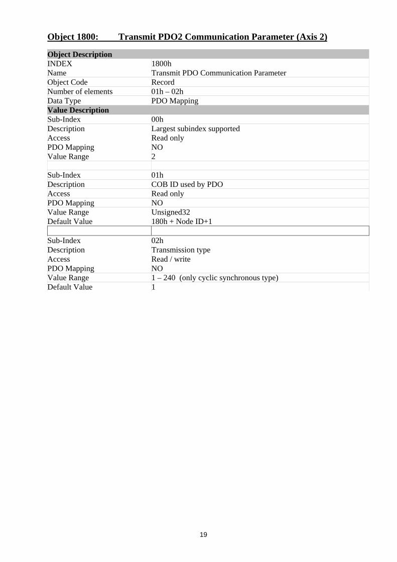
Object 1800: Transmit PDO1 Communication Parameter (Axis 1)
Object DescriptionINDEX 1800hName Transmit PDO Communication ParameterObject Code RecordNumber of elements 01h – 02hData Type PDO MappingValue DescriptionSub-Index 00hDescription Largest subindex supportedAccess Read onlyPDO Mapping NOValue Range 2
Sub-Index 01hDescription COB ID used by PDOAccess Read onlyPDO Mapping NOValue Range Unsigned32Default Value 180h + Node ID
Sub-Index 02hDescription Transmission typeAccess Read / writePDO Mapping NOValue Range 1 – 240 (only cyclic synchronous type)Default Value 1
19
Object 1800: Transmit PDO2 Communication Parameter (Axis 2)
Object DescriptionINDEX 1800hName Transmit PDO Communication ParameterObject Code RecordNumber of elements 01h – 02hData Type PDO MappingValue DescriptionSub-Index 00hDescription Largest subindex supportedAccess Read onlyPDO Mapping NOValue Range 2
Sub-Index 01hDescription COB ID used by PDOAccess Read onlyPDO Mapping NOValue Range Unsigned32Default Value 180h + Node ID+1
Sub-Index 02hDescription Transmission typeAccess Read / writePDO Mapping NOValue Range 1 – 240 (only cyclic synchronous type)Default Value 1

20
Object 1800: Transmit PDO3 Communication Parameter (Axis 3)
Object DescriptionINDEX 1800hName Transmit PDO Communication ParameterObject Code RecordNumber of elements 01h – 02hData Type PDO MappingValue DescriptionSub-Index 00hDescription Largest subindex supportedAccess Read onlyPDO Mapping NOValue Range 2
Sub-Index 01hDescription COB ID used by PDOAccess Read onlyPDO Mapping NOValue Range Unsigned32Default Value 180h + Node ID + 2
Sub-Index 02hDescription Transmission typeAccess Read / writePDO Mapping NOValue Range 1 – 240 (only cyclic synchronous type)Default Value 1
Object 1A00: Transmit PDO1 Mapping Parameter (Axis 1)
Object DescriptionINDEX 1A00hName Transmit PDO mappingObject Code RecordNumber of elements 01h - 04hData Type PDO Mapping
Value DescriptionSub-Index 00hDescription Number of mapped application objects in PDOAccess Write onlyPDO Mapping NOValue Range Unsigned32Default Value 2
Sub-Index 01h - 04hDescription PDO mapping for the nth application object to be mappedAccess Write onlyPDO Mapping NOValue Range Unsigned32Default Value Sub-index 01: Obj 6041h
Sub index 02: Obj 6044h

21
Object 1A00: Transmit PDO2 Mapping Parameter (Axis 2)
Object DescriptionINDEX 1A00hName Transmit PDO mappingObject Code RecordNumber of elements 01h - 04hData Type PDO Mapping
Value DescriptionSub-Index 00hDescription Number of mapped application objects in PDOAccess Write onlyPDO Mapping NOValue Range Unsigned32Default Value 2
Sub-Index 01h - 04hDescription PDO mapping for the nth application object to be mappedAccess Write onlyPDO Mapping NOValue Range Unsigned32Default Value Sub-index 01: Obj 6841h
Sub index 02: Obj 6844h
Object 1A00: Transmit PDO3 Mapping Parameter (Axis 3)
Object DescriptionINDEX 1A00hName Transmit PDO mappingObject Code RecordNumber of elements 01h - 04hData Type PDO Mapping
Value DescriptionSub-Index 00hDescription Number of mapped application objects in PDOAccess Write onlyPDO Mapping NOValue Range Unsigned32Default Value 2
Sub-Index 01h - 04hDescription PDO mapping for the nth application object to be mappedAccess Write onlyPDO Mapping NOValue Range Unsigned32Default Value Sub-index 01: Obj 7041h
Sub index 02: Obj 7044h

22
Object 2000: Activate/Deactive TxPDO
Object DescriptionINDEX 2000hName Activate/Deactivate TxPDOObject Code VarData Type Unsigned 8
Value DescriptionAccess Read / WritePDO Mapping NoValue Range 0 - 7Default Value 07h (TxPDO1, TxPDO2, TxPDO3 activated)
Value:
b7 b6 b5 b4 b3 b2 b1 b0 TxPDO3 TxPDO2 TxPDO10 0 0 0 0 0 0 0 not active not active not active0 0 0 0 0 0 0 1 not active not active active0 0 0 0 0 0 1 0 not active active not active0 0 0 0 0 0 1 1 not active active active0 0 0 0 0 1 0 0 active not active not active0 0 0 0 0 1 0 1 active not active active0 0 0 0 0 1 1 0 active active not active0 0 0 0 0 1 1 1 active active active
Ax3 Ax2 Ax1

23
Fig.6.1 State Machine
Start
Not Ready to Switch ON
Switch ON Disabled (40h)
Ready to Switch ON (21h)
Switched ON (23h)
Operation Enable (07h) Quickstop Active (17h)
Fault (0Fh)
Power Disabled
Power Enabled
Fault
Shutdown Quickstop
Shutdown
Shutdown
Switch ON
Enable Operation Disable Operation
DisableVoltage
DisableVoltage
DisableVoltage
Quickstop
Quickstop
Reset Fault

24
Object 6040: Controlword - Axis 1
Object DescriptionINDEX 6040hName ControlwordObject Code VarData Type Unsigned 16
Value DescriptionAccess Read / WritePDO Mapping PossibleValue Range 0 - 65535Default Value (See Fig.6.1 State Machine Diagram)

25
Tab.6.2 Controlword
Transition From To Command Standard Moog Italiana 6040 (hex)1 Not Ready to Switch On Switch On Disabled2 Switch On Disabled Ready to Switch On Shutdown x x x x x 1 1 0 x x x x x 1 1 0 x63 Ready to Switch On Switched On Switch On x x x x x 1 1 1 x x x x x 1 1 1 x74 Switched On Operation Enable Enable Operation x x x x 1 1 1 1 x x x x 1 1 1 1 xF
5 Operation Enable Switched On Disable Operation x x x x 0 1 1 1 x x x x 0 1 1 1 x76 Switched On Ready to Switch On Shutdown x x x x x 1 1 0 x x x x x 1 1 0 x67 Ready to Switch On Switch On Disabled Quick Stop x x x x x 0 1 x x x x x x 0 1 x x28 Operation Enable Ready to Switch On Shutdown x x x x x 1 1 0 x x x x x 1 1 0 x69 Operation Enable Switch On Disabled Disable Voltage x x x x x x 0 x x x x x x x 0 x x0
Disable Voltage x x x x x x 0 x x x x x x x 0 x x010 Switched On Switch On Disabled
Quick Stop x x x x x 0 1 x x x x x x 0 1 x x211 Operation Enable Switch On Disabled Quick Stop x x x x x 0 1 x x x x x x 0 1 x x2
15 Fault Switch On Disabled Reset Fault 1 x x x x x x x x x x x x x x x 8xb b b b b b b b b b b b b b b b7 6 5 4 3 2 1 0 7 6 5 4 3 2 1 0
26
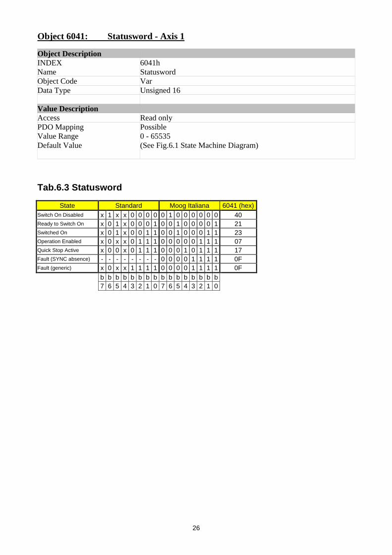
Object 6041: Statusword - Axis 1
Object DescriptionINDEX 6041hName StatuswordObject Code VarData Type Unsigned 16
Value DescriptionAccess Read onlyPDO Mapping PossibleValue Range 0 - 65535Default Value (See Fig.6.1 State Machine Diagram)
Tab.6.3 Statusword
State Standard Moog Italiana 6041 (hex)Switch On Disabled x 1 x x 0 0 0 0 0 1 0 0 0 0 0 0 40Ready to Switch On x 0 1 x 0 0 0 1 0 0 1 0 0 0 0 1 21Switched On x 0 1 x 0 0 1 1 0 0 1 0 0 0 1 1 23Operation Enabled x 0 x x 0 1 1 1 0 0 0 0 0 1 1 1 07Quick Stop Active x 0 0 x 0 1 1 1 0 0 0 1 0 1 1 1 17Fault (SYNC absence) - - - - - - - - 0 0 0 0 1 1 1 1 0FFault (generic) x 0 x x 1 1 1 1 0 0 0 0 1 1 1 1 0F
b b b b b b b b b b b b b b b b7 6 5 4 3 2 1 0 7 6 5 4 3 2 1 0

27
Object 6042: Target Velocity - Axis 1
Object DescriptionINDEX 6042hName Target VelocityObject Code VarData Type Integer 16
Value DescriptionAccess Read / WritePDO Mapping PossibleValue Range - 32768 / 32767Default Value 0
Object 6043: Velocity Demand - Axis 1
Object DescriptionINDEX 6043hName Velocity DemandObject Code VarData Type Integer 16
Value DescriptionAccess Read OnlyPDO Mapping PossibleValue Range - 32768 / 32767Default Value (drive output variable)

28
Object 6044: Control Effort - Axis 1
Object DescriptionINDEX 6044hName Control EffortObject Code VarData Type Integer 16
Value DescriptionAccess Read OnlyPDO Mapping PossibleValue Range - 32768 / 32767Default Value (drive output variable)
Object 6046: Velocity min-max amount - Axis 1
Object DescriptionINDEX 6046hName Velocity min-max amountObject Code ArrayNumber of elements 2Data Type Unsigned 16
Value DescriptionSub-Index 01hDescription Velocity min amountAccess Read / WritePDO Mapping PossibleValue Range Unsigned 16Default Value 00h
Sub-Index 02hDescription Velocity max amountAccess Read / WritePDO Mapping PossibleValue Range Unsigned16Default Value 0C00h

29
Object 6048: Velocity acceleration - Axis 1
Object DescriptionINDEX 6048hName Velocity accelerationObject Code RecordNumber of elements 1Data Type Unsigned 16
Value DescriptionSub-Index 02hDescription Delta TimeAccess Read / WritePDO Mapping NOValue Range Unsigned 16Default Value 00h
Object 6049: Velocity deceleration - Axis 1
Object DescriptionINDEX 6049hName Velocity decelerationObject Code RecordNumber of elements 1Data Type Unsigned 16
Value DescriptionSub-Index 02hDescription Delta TimeAccess Read / WritePDO Mapping NOValue Range Unsigned 16Default Value 00h
Object 6060: Modes of Operation - Axis 1
Object DescriptionINDEX 6060hName Modes of OperationObject Code VarData Type Integer 8
Value DescriptionAccess Write OnlyPDO Mapping NOValue Range 01h - 02hDefault Value 02h (velocity mode)
30
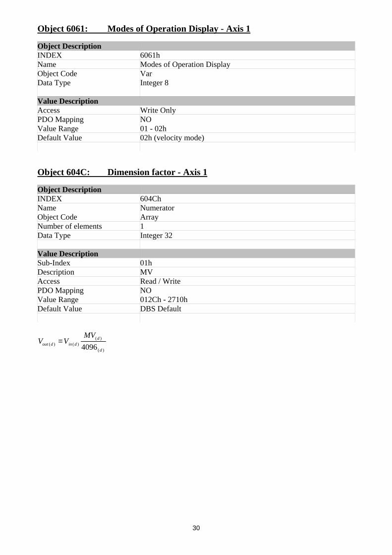
Object 6061: Modes of Operation Display - Axis 1
Object DescriptionINDEX 6061hName Modes of Operation DisplayObject Code VarData Type Integer 8
Value DescriptionAccess Write OnlyPDO Mapping NOValue Range 01 - 02hDefault Value 02h (velocity mode)
Object 604C: Dimension factor - Axis 1
Object DescriptionINDEX 604ChName NumeratorObject Code ArrayNumber of elements 1Data Type Integer 32
Value DescriptionSub-Index 01hDescription MVAccess Read / WritePDO Mapping NOValue Range 012Ch - 2710hDefault Value DBS Default
)(
)()()( 4096d
ddindout
MVVV =

31
Object 6510: DBM Parameter
Object DescriptionINDEX 6510hName DBM ParameterObject Code ArrayNumber of elements 3Data Type Integer 8
Value DescriptionSub-Index 01hDescription KP - Proportional GainAccess Read / WritePDO Mapping NOValue Range 00h - FFhDefault Value DBM default
Sub-Index 02hDescription KI – Integral GainAccess Read / WritePDO Mapping NOValue Range 00h - FFhDefault Value DBM Default
Sub-Index 03hDescription IL – Current LimitAccess Read / WritePDO Mapping NOValue Range 00 - 64hDefault Value DBM Default
Object 67FF: Device Type – Axis 1
Object DescriptionINDEX 67FFhName Device TypeObject Code VarData Type Unsigned 32
Value DescriptionAccess Read onlyPDO Mapping NOValue Range Unsigned32Default Value 00020402h

32
Object 6840: Controlword - Axis 2
Object DescriptionINDEX 6840hName ControlwordObject Code VarData Type Unsigned 16
Value DescriptionAccess Read / WritePDO Mapping PossibleValue Range 0 – 65535Default Value (See Fig.6.1 State Machine Diagram)
Object 6841: Statusword - Axis 2
Object DescriptionINDEX 6841hName StatuswordObject Code VarData Type Unsigned 16
Value DescriptionAccess Read onlyPDO Mapping PossibleValue Range 0 – 65535Default Value (See Fig.6.1 State Machine Diagram)
Object 6842: Target Velocity - Axis 2
Object DescriptionINDEX 6842hName Target VelocityObject Code VarData Type Integer 16
Value DescriptionAccess Read / WritePDO Mapping PossibleValue Range - 32768 / 32767Default Value 0

33
Object 6843: Velocity Demand - Axis 2
Object DescriptionINDEX 6843hName Velocity DemandObject Code VarData Type Integer 16
Value DescriptionAccess Read OnlyPDO Mapping PossibleValue Range - 32768 / 32767Default Value (drive output variable)
Object 6844: Control Effort - Axis 2
Object DescriptionINDEX 6844hName Control EffortObject Code VarData Type Integer 16
Value DescriptionAccess Read OnlyPDO Mapping PossibleValue Range - 32768 / 32767Default Value (drive output variable)
Object 6846: Velocity min-max amount - Axis 2
Object DescriptionINDEX 6846hName Velocity min-max amountObject Code ArrayNumber of elements 2Data Type Unsigned 16
Value DescriptionSub-Index 01hDescription Velocity min amountAccess Read / WritePDO Mapping PossibleValue Range Unsigned 16Default Value 00h
Sub-Index 02hDescription Velocity max amountAccess Read / WritePDO Mapping PossibleValue Range Unsigned16Default Value 0C00h

34
Object 6848: Velocity acceleration - Axis 2
Object DescriptionINDEX 6848hName Velocity accelerationObject Code RecordNumber of elements 1Data Type Unsigned 16
Value DescriptionSub-Index 02hDescription Delta TimeAccess Read / WritePDO Mapping NOValue Range Unsigned 16Default Value 00h
Object 6849: Velocity deceleration - Axis 2
Object DescriptionINDEX 6849hName Velocity decelerationObject Code RecordNumber of elements 1Data Type Unsigned 16
Value DescriptionSub-Index 02hDescription Delta TimeAccess Read / WritePDO Mapping NOValue Range Unsigned 16Default Value 00h
Object 6860: Modes of Operation - Axis 2
Object DescriptionINDEX 6860hName Modes of OperationObject Code VarData Type Integer 8
Value DescriptionAccess Write OnlyPDO Mapping NOValue Range 01h - 02hDefault Value 02h (velocity mode)

35
Object 6861: Modes of Operation Display - Axis 2
Object DescriptionINDEX 6861hName Modes of Operation DisplayObject Code VarData Type Integer 8
Value DescriptionAccess Write OnlyPDO Mapping NOValue Range 01h – 02hDefault Value 02h (velocity mode)
Object 684C: Dimension factor - Axis 2
Object DescriptionINDEX 684ChName NumeratorObject Code ArrayNumber of elements 1Data Type Integer 32
Value DescriptionSub-Index 01hDescription MVAccess Read / WritePDO Mapping NOValue Range 012Ch – 2710hDefault Value DBS Default
)(
)()()( 4096d
ddindout
MVVV =
36
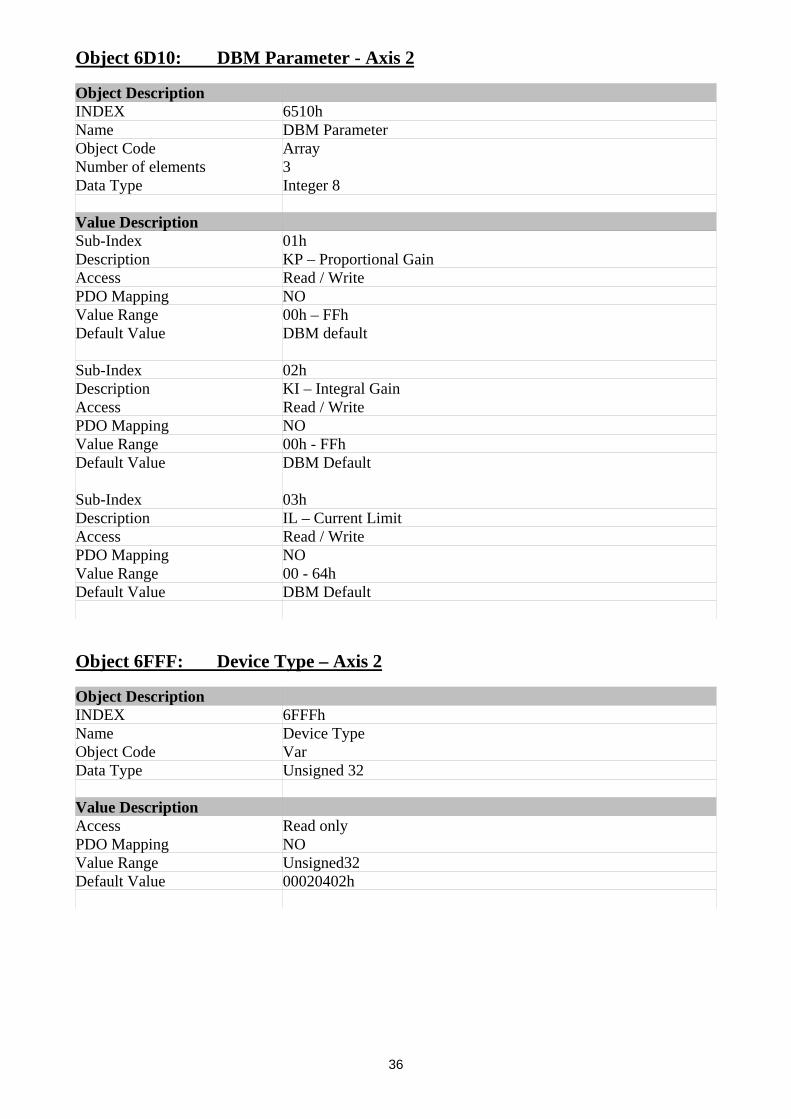
Object 6D10: DBM Parameter - Axis 2
Object DescriptionINDEX 6510hName DBM ParameterObject Code ArrayNumber of elements 3Data Type Integer 8
Value DescriptionSub-Index 01hDescription KP – Proportional GainAccess Read / WritePDO Mapping NOValue Range 00h – FFhDefault Value DBM default
Sub-Index 02hDescription KI – Integral GainAccess Read / WritePDO Mapping NOValue Range 00h - FFhDefault Value DBM Default
Sub-Index 03hDescription IL – Current LimitAccess Read / WritePDO Mapping NOValue Range 00 - 64hDefault Value DBM Default
Object 6FFF: Device Type – Axis 2
Object DescriptionINDEX 6FFFhName Device TypeObject Code VarData Type Unsigned 32
Value DescriptionAccess Read onlyPDO Mapping NOValue Range Unsigned32Default Value 00020402h

37
Object 7040: Controlword - Axis 3
Object DescriptionINDEX 7040hName ControlwordObject Code VarData Type Unsigned 16
Value DescriptionAccess Read / WritePDO Mapping PossibleValue Range 0 - 65535Default Value (See Fig.6.1 State Machine Diagram)
Object 7041: Statusword - Axis 3
Object DescriptionINDEX 7041hName StatuswordObject Code VarData Type Unsigned 16
Value DescriptionAccess Read onlyPDO Mapping PossibleValue Range 0 - 65535Default Value (See Fig.6.1 State Machine Diagram)
Object 7042: Target Velocity - Axis 3
Object DescriptionINDEX 7042hName Target VelocityObject Code VarData Type Integer 16
Value DescriptionAccess Read / WritePDO Mapping PossibleValue Range - 32768 / 32767Default Value 0

38
Object 7043: Velocity Demand - Axis 3
Object DescriptionINDEX 7043hName Velocity DemandObject Code VarData Type Integer 16
Value DescriptionAccess Read OnlyPDO Mapping PossibleValue Range - 32768 / 32767Default Value (drive output variable)
Object 7044: Control Effort - Axis 3
Object DescriptionINDEX 7044hName Control EffortObject Code VarData Type Integer 16
Value DescriptionAccess Read OnlyPDO Mapping PossibleValue Range - 32768 / 32767Default Value (drive output variable)
Object 7046: Velocity min-max amount - Axis 3
Object DescriptionINDEX 7046hName Velocity min-max amountObject Code ArrayNumber of elements 2Data Type Unsigned 16
Value DescriptionSub-Index 01hDescription Velocity min amountAccess Read / WritePDO Mapping PossibleValue Range Unsigned 16Default Value 00h
Sub-Index 02hDescription Velocity max amountAccess Read / WritePDO Mapping PossibleValue Range Unsigned16Default Value 0C00h
39
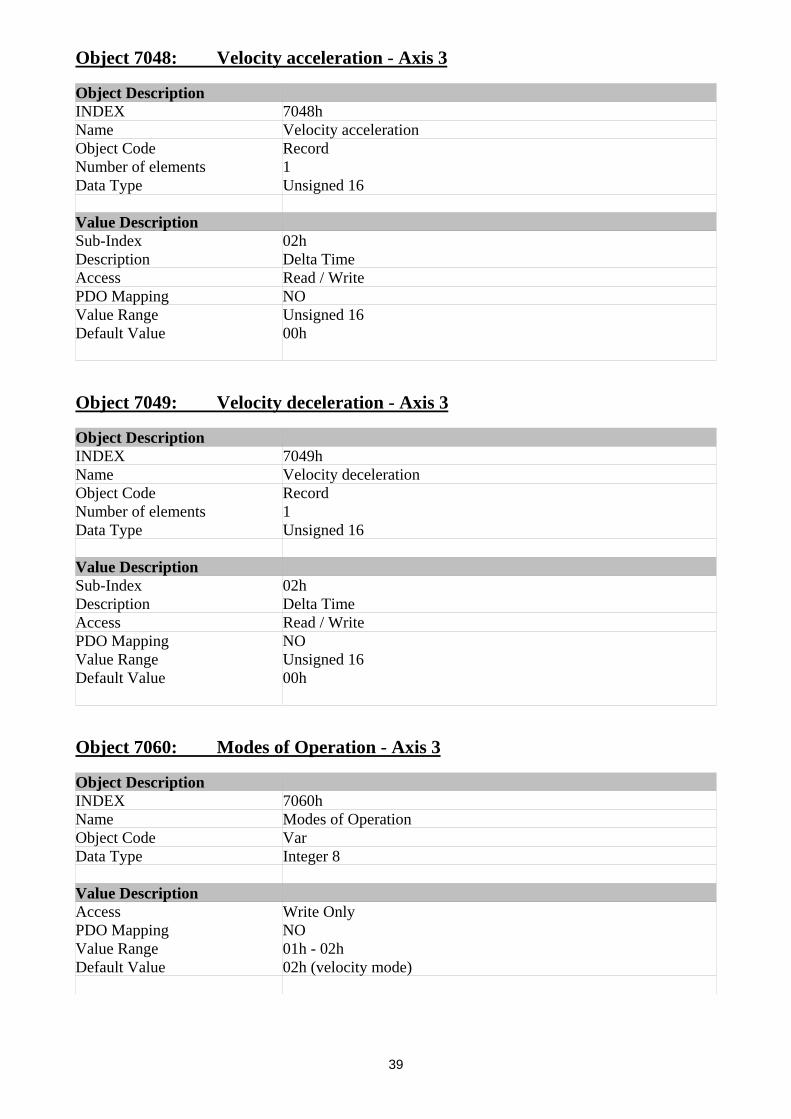
Object 7048: Velocity acceleration - Axis 3
Object DescriptionINDEX 7048hName Velocity accelerationObject Code RecordNumber of elements 1Data Type Unsigned 16
Value DescriptionSub-Index 02hDescription Delta TimeAccess Read / WritePDO Mapping NOValue Range Unsigned 16Default Value 00h
Object 7049: Velocity deceleration - Axis 3
Object DescriptionINDEX 7049hName Velocity decelerationObject Code RecordNumber of elements 1Data Type Unsigned 16
Value DescriptionSub-Index 02hDescription Delta TimeAccess Read / WritePDO Mapping NOValue Range Unsigned 16Default Value 00h
Object 7060: Modes of Operation - Axis 3
Object DescriptionINDEX 7060hName Modes of OperationObject Code VarData Type Integer 8
Value DescriptionAccess Write OnlyPDO Mapping NOValue Range 01h - 02hDefault Value 02h (velocity mode)

40
Object 7061: Modes of Operation Display - Axis 3
Object DescriptionINDEX 7061hName Modes of Operation DisplayObject Code VarData Type Integer 8
Value DescriptionAccess Write OnlyPDO Mapping NOValue Range 01h - 02hDefault Value 02h (velocity mode)
Object 704C: Dimension factor - Axis 3
Object DescriptionINDEX 704ChName NumeratorObject Code ArrayNumber of elements 1Data Type Integer 32
Value DescriptionSub-Index 01hDescription MVAccess Read / WritePDO Mapping NOValue Range 012Ch - 2710hDefault Value DBS Default
)(
)()()( 4096d
ddindout
MVVV =

41
Object 7510: DBM Parameter - Axis 3
Object DescriptionINDEX 7510hName DBM ParameterObject Code ArrayNumber of elements 3Data Type Integer 8
Value DescriptionSub-Index 01hDescription KP – Proportional GainAccess Read / WritePDO Mapping NOValue Range 00h - FFhDefault Value DBM default
Sub-Index 02hDescription KI – Integral GainAccess Read / WritePDO Mapping NOValue Range 00h - FFhDefault Value DBM Default
Sub-Index 03hDescription IL – Current LimitAccess Read / WritePDO Mapping NOValue Range 00 – 64hDefault Value DBM Default
Object 77FF: Device Type – Axis 3
Object DescriptionINDEX 77FFhName Device TypeObject Code VarData Type Unsigned 32
Value DescriptionAccess Read onlyPDO Mapping NOValue Range Unsigned32Default Value 00020402h

42
CAN data:
Byte Bit7 Bit6 Bit5 Bit4 Bit3 Bit2 Bit1 Bit0 Hex
Byte0 1 0 0 0 0 0 0 0 80Byte1 xx xx xx xx xx xx xx xx xx LSB IndexByte2 xx xx xx xx xx xx xx xx xx MSB IndexByte3 xx xx xx xx xx xx xx xx xx subindexByte4 AC0.7 AC0.6 AC0.5 AC0.4 AC0.3 AC0.2 AC0.1 AC0.0 xx AC 0Byte5 AC1.7 AC1.6 AC1.5 AC1.4 AC1.3 AC1.2 AC1.1 AC1.0 xx AC 1Byte6 EC0.7 EC0.6 EC0.5 EC0.4 EC0.3 EC0.2 EC0.1 EC0.0 xx EC 0Byte7 CL1.7 CL1.6 CL1.5 CL1.4 CL1.3 CL1.2 CL1.1 CL1.0 xx CL 1
Object NOT available: Sub Index NOT available:AC 0 = 00 AC 0 = 11AC 1 = 00 AC 1 = 00EC 0 = 02 EC 0 = 09CL 1 = 06 CL 1 = 06
Value range exceeded: Object cannot be mappedAC 0 = 30 AC 0 = 41AC 1 = 00 AC 1 = 00EC 0 = 09 EC 0 = 04CL 1 = 06 CL 1 = 06
Data cannot be storedAC 0 = 20AC 1 = 00EC 0 = 00CL 1 = 08

Moog Italiana S.r.l.Electric DivisionVia Avosso, 9416015 Casella GEItalyPhone: (+39) 010 9671Fax: (+39) 010 9671 280
GB-4536 Dec/00 Moog Italiana Srl reserves the right to alter any dimensions or data without prior notice Printed in Italy


![22.10.2010 SVN Accounts [NPFL094:/] … vojtech.diatka = rw ejemr = rw machacekmatous = rw sedlak = rw masekj = rw](https://img.pdfslide.net/doc/110x75/56649e115503460f94afcb54/22102010httpufalmffcuniczcoursenpfl0941-svn-accounts-npfl094.jpg)