Embed Size (px)
Citation preview

DC 4.4
REPORT ON THE SYNTHESIZES OF THE PROJECT AND LESSONS LEARNT

Report on the synthesizes of the project and lessons learnt
Date: 28.05.2010
Ref.: DIANA-DA-DC-4.4
Ed.: 1.0
- 2 - No part of this report may be used, reproduced and/or disclosed in any form or by any means without the prior written permission of the DIANA project partners.
© 2010 – All rights reserved
Project Name: Distributed equipment Independent environment for Advanced avioNics Applications
Programme: Contract Nº: AST-CT-2006-030985 Start: 13/12/2006 Coordinator: Skysoft Portugal Duration: 36 months
Document Title: REPORT ON THE SYNTHESIZES OF THE PROJECT AND LESSONS
LEARNT
Document Ref.: DIANA-DA-DC-4.4 Edition: 1.0 Date: 28.05.2010 Status: Release
Compiled by: Title: WP 4.4 Leader Damien Carbonne Date: Insert Date Here
Approved by: Title: DIANA Quality Manager António Costa Date: Insert Date Here
Authorised by: Title: DIANA Project Manager Tobias Schoofs Date: Insert Date Here
Dissemination Level
PU Public X PP Restricted to other programme participants (including the Commission Services) RE Restricted to a group specified by the consortium (including the Commission Services) CO Confidential, only for members of the consortium (including the Commission Services)

Report on the synthesizes of the project and lessons learnt
Date: 28.05.2010
Ref.: DIANA-DA-DC-4.4
Ed.: 1.0
- 3 - No part of this report may be used, reproduced and/or disclosed in any form or by any means without the prior written permission of the DIANA project partners.
© 2010 – All rights reserved
EEXXEECCUUTTIIVVEE SSUUMMMMAARRYY
The main goal of DIANA was to define an enhanced avionics platform, AIDA – Architecture for Independent Distributed Avionics – and its supporting development environment. AIDA had to provide secure distribution and execution over virtual machines to avionics applications in order to support and ease development and maintenance of ever growing avionics application size, complexity, and certification efforts.
This project that started in December 2006 and that was initially planned to last 3 years, was extended by 6 months to handle its ambitious technical objectives. This report constitutes the final synthesis and conclusion of all results achieved by DIANA.
Many technologies have been investigated, some being widely used in IT domains, such as Java, Data Distribution Services, Model Based Engineering, some others being much less common, even in more specialized domains, such as formal methods. One DIANA guideline was to allow the use of those technologies while being compliant with existing avionics standards such as ARINC 653.
Even if certain problems have not been fully solved in the course of the project, its overall results are positive. Here are some examples:
� The use of Java for real-time safety critical application has been deeply investigated. A Java API has been defined for ARINC 653, while preserving properties of the Java threading model. The PERC Pico platform has been improved and ported to several underlying OS. Confrontation of results to future DO-178C and associated supplements shows that Java platform is a robust foundation for avionics applications.
� DDS appears to be a good amplification of ARINC 653 concepts, and seems more adapted than CORBA that was initially envisaged. Much work remains to accomplish in the middleware area, but this choice seems promising.
� Results obtained for multi-static reconfiguration are also impressive. Formal methods have been used to prove correctness of the used distributed algorithm. Of course, the demonstrator is incomplete, but it has reached a high level of confidence.
� Application of formal methods has been investigated, developed, and particularly applied to the handling of memory allocation with Java. This is a step forward for one of the major issues with the use of Java in safety critical applications.
� Some progress has been done in the domain of Model Transformations. Traceability issues, of primary importance for certification, have particularly been studied, notably for graph-based transformations.
� The different DIANA experiments clearly showed the need for integrated development environments.
� Two different implementations – simulations – have been developed. They integrate most DIANA results, demonstrating the validity of the followed approach.
This report starts by an overview of the DIANA project and of the AIDA platform. It then presents objectives and results achieved by each work package, things that remains to
Report on the synthesizes of the project and lessons learnt
Date: 28.05.2010
Ref.: DIANA-DA-DC-4.4
Ed.: 1.0
- 4 - No part of this report may be used, reproduced and/or disclosed in any form or by any means without the prior written permission of the DIANA project partners.
© 2010 – All rights reserved
be done and therefore possibilities for future work. Some guidelines for future projects are also listed from lessons learnt during DIANA.

Report on the synthesizes of the project and lessons learnt
Date: 28.05.2010
Ref.: DIANA-DA-DC-4.4
Ed.: 1.0
- 5 - No part of this report may be used, reproduced and/or disclosed in any form or by any means without the prior written permission of the DIANA project partners.
© 2010 – All rights reserved
Contributing Partners
Company Name
Skysoft Tobias Schoofs
Skysoft Cássia Tatibana
Alenia Aeronautica Alfio Palatucci
Alenia Aeronautica Andrea Castoldi
Alenia Aeronautica Roberto Audisio
AleniaSIA Ivo Viglietti
Alenia SIA Mássimo Cifaldi
Atego Marc Richard-Foy
Atego Ludovic Gauthier
Budapest University Dániel Varro
Budapest University Ákos Horváth
Budapest University Gergely Pintér
Embraer José Ricardo Parizi Negrão
Embraer Marco Ortiz
Embraer Rodrigo Matos de Azeredo Coutinho
NLR Klaas Wiegmink
NLR Bert Schultheiss
Thales Avionics Eric Jenn
University of Karlsruhe Peter Schmitt
University of Karlsruhe Christian Engel
Dassault Aviation Damien Carbonne
Distribution List
Company Name
European Commission Francesco Lorubbio
Alenia Aeronautica Alfio Palatucci
Alenia Aeronautica Andrea Castoldi
Alenia Aeronautica Roberto Audisio
Atego Ludovic Gauthier
Atego Marc Richard-Foy
Budapest University Ákos Horváth

Report on the synthesizes of the project and lessons learnt
Date: 28.05.2010
Ref.: DIANA-DA-DC-4.4
Ed.: 1.0
- 6 - No part of this report may be used, reproduced and/or disclosed in any form or by any means without the prior written permission of the DIANA project partners.
© 2010 – All rights reserved
Budapest University Dániel Varro
Dassault Aviation Damien Carbonne
Embraer José Ricardo Parizi Negrão
Embraer Marco Ortiz
Embraer Rodrigo Matos de Azeredo Coutinho
NLR Bert Schultheiss
NLR Klaas Wiegmink
NLR René Wiegers
NLR Roelof Vos
Skysoft Cássia Tatibana
Skysoft José Neves
Skysoft Tobias Schoofs
Alenia SIA Anna Todino
Alenia SIA Francesco Lanteri
Alenia SIA Ivo Viglietti
Alenia SIA Mássimo Cifaldi
Thales Avionics Christophe Bouleau
Thales Avionics Eric Jenn
Thales Avionics Stéphane Leriche
Karlsruhe Institute of Technology Christian Engel
Karlsruhe Institute of Technology Peter Schmitt
Document Change Log
Version Date Author Modified
Sections / Pages
Comments
0.01 16/02/2010 Damien Carbonne All First draft
0.02 25/02/2010 Tobias Schoofs All Changes of document structure
0.03 23/04/2010
Christian Engels Damien Carbonne
Ákos Horváth Tobias Schoofs
4.6 5.2
First contributions Structure change (WP oriented)
0.04 30/04/2010 Tobias Schoofs 2, 3, 4, 5 Contributions on project overview, AIDA overview, requirements, Interoperability Overview
0.05 05/05/2010 Tobias Schoofs
Ludovic Gauthier Marc Richard-Foy
5 Contributions to
- Execution Environment - Interoperability
0.06 06/05/2010 Damien Carbonne 4.1 5.2.5
Dissemination level changed to PU Contributions to
- Requirement Gathering Process

Report on the synthesizes of the project and lessons learnt
Date: 28.05.2010
Ref.: DIANA-DA-DC-4.4
Ed.: 1.0
- 7 - No part of this report may be used, reproduced and/or disclosed in any form or by any means without the prior written permission of the DIANA project partners.
© 2010 – All rights reserved
- ICD
0.07 07/05/2010
Ákos Horváth Tobias Schoofs Klaas Wiegmink
Damien Carbonne
1 2.4 6
7.2
Distribution List Contributions to
- Performance - Demonstration objectives - Scientific papers - AIDA evaluation
0.08 12/05/2010
Ákos Horváth Alfio Palatucci
Andrea Castoldi Mássimo Cifaldi
Damien Carbonne
1.5 5.2.2 5.4
Abbreviations & Acronyms AIDA Broker Certification considerations
0.09 13/05/2010 Tobias Schoofs 2,3,4,5,7
Finalised 2,3,4,5 (some minor comments still open, request for review by ALA in 4.3) 7.1 and 7.2 finalised. Open:
- 6.1 Objectives (new!) - 6.2/3 FWS - 6.4 Results - 7.3 (Events) - 8
0.10 17/05/2010 Tobias Schoofs 6, 7 Finalised 7; added a first version to 6.1 (not yet perfect).
0.11 17/05/2010 Damien Carbonne 5.4 Certification aspects
0.12 18/05/2010 Jose Ricardo Parizi Negrão 6 FWS sections (first version)
0.13 18/05/2010 Damien Carbonne
Ivo Viglietti Tobias Schoofs
9, … Executive Summary Corrections Conclusion
0.14 19/05/2010
E. Jenn Klaas Wiegmink Bert Schultheiss
Ivo Viglietti
5.4 All sections
Corrections Took into account part of review comments
0.15 20/05/2010
Damien Carbonne Tobias Schoofs
Ivo Viglietti Klaas Wiegmink Bert Schultheiss
Ákos Horváth
All sections More review comments
0.16 21/05/2010
Damien Carbonne Cássia Tatibana Tobias Schoofs Akos Horváth Peter Schmitt Alfio Palatucci
Ivo Viglietti
7.4 8
Table 2 …
Figures Guidelines Relation to other Projects
0.17 24/05/2010 Tobias Schoofs All Final Technical Review
1.0 28/05/2010 Tobias Schoofs All Release

Report on the synthesizes of the project and lessons learnt
Date: 28.05.2010
Ref.: DIANA-DA-DC-4.4
Ed.: 1.0
- 8 - No part of this report may be used, reproduced and/or disclosed in any form or by any means without the prior written permission of the DIANA project partners.
© 2010 – All rights reserved
TTAABBLLEE OOFF CCOONNTTEENNTTSS
1 INTRODUCTION ................................................................................................................ 12 1.1 Project Description ...................................................................................................... 12 1.2 Purpose and Scope ..................................................................................................... 12 1.3 Document Structure..................................................................................................... 12 1.4 Reference Documents ................................................................................................. 13 1.5 Abbreviations and Acronyms ....................................................................................... 14
2 PROJECT OVERVIEW ....................................................................................................... 16 2.1 Project Objectives........................................................................................................ 16 2.2 Study Logic .................................................................................................................. 17 2.3 Structure ...................................................................................................................... 17 2.4 Performance ................................................................................................................ 19
3 AIDA OVERVIEW ............................................................................................................... 23 3.1 Neutrality ..................................................................................................................... 24 3.2 Interoperability ............................................................................................................. 25
3.2.1 AIDA Broker ........................................................................................................... 25 3.2.2 AIDA Services ........................................................................................................ 25
3.2.2.1 ARINC653 Required Services ..................................................................... 26 3.2.2.2 ARINC653 Extended Services .................................................................... 27 3.2.2.3 Local Services ............................................................................................. 27 3.2.2.4 Remote Services ......................................................................................... 27 3.2.2.5 Compound Services .................................................................................... 28 3.2.2.6 Inter-Application Services ............................................................................ 28 3.2.2.7 Predefined Service Components ................................................................. 29
3.2.3 AIDA Setup Phases ............................................................................................... 30 3.3 AIDA Development Process ........................................................................................ 30
4 WP 1: REQUIREMENTS .................................................................................................... 32 4.1 Requirements Gathering Process ............................................................................... 32
4.1.1 Civil avionics .......................................................................................................... 32 4.1.2 Development means .............................................................................................. 33
4.2 Overview on Requirements ......................................................................................... 34 4.2.1 Strategic requirements........................................................................................... 34 4.2.2 Innovative Aspects................................................................................................. 35 4.2.3 Challenges ............................................................................................................. 40
5 WP2 AND 3: AIDA DEVELOPMENT .................................................................................. 45 5.1 The Neutral Execution Environment............................................................................ 45
5.1.1 The Runtime .......................................................................................................... 45 5.1.2 AIDA Computational Model ................................................................................... 46
5.1.2.1 Program States ............................................................................................ 46 5.1.2.2 Concurrency ................................................................................................ 47 5.1.2.3 Memory ........................................................................................................ 48 5.1.2.4 Time ............................................................................................................. 49 5.1.2.5 Interoperability ............................................................................................. 49
5.1.3 Java Neutral Execution Platform Implementation ................................................. 49 5.2 The Interoperability Architecture ................................................................................. 50
5.2.1 Overview ................................................................................................................ 50 5.2.2 The AIDA Broker .................................................................................................... 52
5.2.2.1 AIDA Vision ................................................................................................. 52 5.2.2.2 The Service concept .................................................................................... 53 5.2.2.3 The Broker ................................................................................................... 54
5.2.3 The AIDA Logbooks System ................................................................................. 56 5.2.3.1 Declaring AIDA logbooks ............................................................................. 57

Report on the synthesizes of the project and lessons learnt
Date: 28.05.2010
Ref.: DIANA-DA-DC-4.4
Ed.: 1.0
- 9 - No part of this report may be used, reproduced and/or disclosed in any form or by any means without the prior written permission of the DIANA project partners.
© 2010 – All rights reserved
5.2.3.2 AIDA Logbook infrastructure ....................................................................... 58 5.2.3.3 Tool Chain ................................................................................................... 59
5.2.4 The AIDA Reconfiguration Engine ......................................................................... 60 5.2.4.1 Objectives of the AIDA Reconfiguration Engine .......................................... 60 5.2.4.2 Implementation Strategy .............................................................................. 61 5.2.4.3 Mapping to ARINC 653 ................................................................................ 63
5.2.5 The AIDA Interface Control Document .................................................................. 66 5.3 Development Environment .......................................................................................... 68
5.3.1 Model Driven Engineering ..................................................................................... 68 5.3.1.1 Model Driven Development of Safety-Critical Systems ............................... 68 5.3.1.2 The AIDA Development means ................................................................... 69 5.3.1.3 Conclusion and Future Directions ............................................................... 72
5.3.2 Formal Methods ..................................................................................................... 73 5.3.2.1 Environmental Control System Case Study ................................................ 73 5.3.2.2 Byzantine Agreement Protocol .................................................................... 73 5.3.2.3 Memory Contracts ....................................................................................... 74 5.3.2.4 PERC Pico ................................................................................................... 74 5.3.2.5 Formal Verification of Model Transformations............................................. 74
5.3.3 Implementation of the Development Tool Chain in the AIDA Simulator ................ 74 5.4 Certification Aspects .................................................................................................... 76
5.4.1 Use of Java for Safety Critical Embedded Applications ........................................ 76 5.4.2 Model Transformations .......................................................................................... 77 5.4.3 Formal Methods ..................................................................................................... 78 5.4.4 Architecture and Middleware ................................................................................. 79
6 WP4: AIDA EVALUATION SYNTHESIS ............................................................................ 80 6.1 Demonstration Approach ............................................................................................. 80 6.2 Demonstrator Description ............................................................................................ 81
6.2.1 ECS Demonstrator ................................................................................................. 81 6.2.2 FWS Demonstrator ................................................................................................ 83
6.3 Evaluation and Test Description .................................................................................. 85 6.3.1 ECS Demonstrator ................................................................................................. 85
6.3.1.1 Verification of Java execution environment ................................................. 85 6.3.1.2 Verification of exception handling ................................................................ 85 6.3.1.3 Verification of the Logbook service ............................................................. 85 6.3.1.4 Verification of multi-static behaviour ............................................................ 85
6.3.2 FWS Demonstrator ................................................................................................ 86 6.4 Results ......................................................................................................................... 87
7 WP5: DISSEMINATION ...................................................................................................... 89 7.1 Objectives and Means ................................................................................................. 89 7.2 Scientific Papers .......................................................................................................... 89
7.2.1 Aspects of “Architecture for Independent Distributed Avionics”, DASC 2008 ....... 89 7.2.2 Tool Support for Engineering Certifiable Software, SafeCert 2008 ....................... 90 7.2.3 CSP(M): Constraints Satisfaction Problem over Models, MODELS 2009 ............ 90 7.2.4 Workflow-Driven Tool Integration Using Model Transformations, Manfred Nagl Festschrift, 2010 (Springer book chapter) .......................................................................... 90 7.2.5 Towards Certifiable Model Transformations: A Survey, Submitted to ACM Survey, 2010 91 7.2.6 Model-Driven Development of ARINC 653 Configuration Tables, DASC 2010 .... 91 7.2.7 Use of PERC Pico in the AIDA Avionics Platform, JTRES 2009 and ERTS 2010 91 7.2.8 Enhanced Dispatchability of Aircrafts, using Multi-Static Configurations, ERTS 2010 91
7.3 Events .......................................................................................................................... 92 7.3.1 Farnborough 2008 ................................................................................................. 92 7.3.2 Avionics 2010 ........................................................................................................ 92
7.4 Relation to other Projects ............................................................................................ 93 7.4.1 DECOS .................................................................................................................. 93 7.4.2 MOGENTES .......................................................................................................... 94

Report on the synthesizes of the project and lessons learnt
Date: 28.05.2010
Ref.: DIANA-DA-DC-4.4
Ed.: 1.0
- 10 - No part of this report may be used, reproduced and/or disclosed in any form or by any means without the prior written permission of the DIANA project partners.
© 2010 – All rights reserved
7.4.3 SCARLETT ............................................................................................................ 94 7.4.4 JEOPARD .............................................................................................................. 94 7.4.5 GENESYS ............................................................................................................. 95 7.4.6 INDEXYS ............................................................................................................... 95
8 GUIDELINES FOR FUTURE PROJECTS ......................................................................... 96 8.1 Technical Concerns ..................................................................................................... 96 8.2 Management Concerns ............................................................................................... 96
8.2.1 Adopt a more iterative / incremental approach ...................................................... 96 8.2.2 Adopt specific licences for reusable work.............................................................. 96 8.2.3 Technology Availability .......................................................................................... 97
9 CONCLUSION .................................................................................................................... 98 10 GLOSSARY ...................................................................................................................... 100

Report on the synthesizes of the project and lessons learnt
Date: 28.05.2010
Ref.: DIANA-DA-DC-4.4
Ed.: 1.0
- 11 - No part of this report may be used, reproduced and/or disclosed in any form or by any means without the prior written permission of the DIANA project partners.
© 2010 – All rights reserved
LLIISSTT OOFF FFIIGGUURREESS
Figure 1: DIANA Study Logic ...................................................................................................... 17 Figure 2: Work Breakdown Structure .......................................................................................... 18 Figure 3: Effort Consumption per Period ..................................................................................... 20 Figure 4: AIDA Architecture ......................................................................................................... 23 Figure 5: Interaction with Remote Services ................................................................................ 27 Figure 6: Overview of the Model Architecture ............................................................................. 31 Figure 7: Addressed issues and their relationships .................................................................... 33 Figure 8: AIDA applications and partitions .................................................................................. 38 Figure 9: Neutral Execution Platform Architecture ...................................................................... 45 Figure 10: Program States Diagram ........................................................................................... 47 Figure 11: Thread States Diagram .............................................................................................. 48 Figure 12: communication architecture concepts ........................................................................ 53 Figure 13: Services dependencies .............................................................................................. 53 Figure 14: Relation among Topic and Data Type ....................................................................... 55 Figure 15: The Broker architecture.............................................................................................. 56 Figure 16: AIDA Logbook services request ................................................................................. 58 Figure 17: Configuration Application ........................................................................................... 61 Figure 18: Startup Sequence ...................................................................................................... 62 Figure 19: Manager Deployment ................................................................................................. 63 Figure 20: Module Manager Interoperability ............................................................................... 64 Figure 21: Component Interaction ............................................................................................... 65 Figure 22: Process Interaction .................................................................................................... 66 Figure 23: ICD levels ................................................................................................................... 67 Figure 24: meta-ICD packages organization ............................................................................... 67 Figure 25: MDD process for Safety Critical Development .......................................................... 69 Figure 26: Overview of the AIDA Model Based Development Process ...................................... 70 Figure 27: Mapping of the AIDA Development Environment to the SIMA Tool Chain ................ 75 Figure 28: Relation between AIDA middleware components, development environment,
execution environment, demonstrators .............................................................................. 81 Figure 29: ECS Demonstrator Architecture ................................................................................. 82 Figure 30: FWS demonstrator architecture ................................................................................. 84 Figure 31: FWS Demonstrator Views .......................................................................................... 84 Figure 32: Multi-static nominal configuration C0 ......................................................................... 86 Figure 33: AIDA Demonstrator at Avionics 2010 ........................................................................ 93
LLIISSTT OOFF TTAABBLLEESS
Table 1: AIDA Services Categories ............................................................................................. 26 Table 2: AIDA Core Service Components ................................................................................... 29 Table 3: AIDA Simulation Components ....................................................................................... 51 Table 4: Tests performed using the FWS demonstrator ............................................................. 86

Report on the synthesizes of the project and lessons learnt
Date: 28.05.2010
Ref.: DIANA-DA-DC-4.4
Ed.: 1.0
- 12 - No part of this report may be used, reproduced and/or disclosed in any form or by any means without the prior written permission of the DIANA project partners.
© 2010 – All rights reserved
11 IINNTTRROODDUUCCTTIIOONN
1.1 Project Description
The DIANA Project is the first step for the implementation of an enhanced avionics platform, named AIDA (Architecture for Independent Distributed Avionics), providing secure distribution and execution on virtual machines to avionics applications.
Along with this objective, DIANA also aims at contributing to the definition and standardization of the development and certification means needed to support this novel platform.
The technological guidelines driving the development of AIDA are:
� to base AIDA development on IME/IMA concepts;
� to enable the execution of object oriented applications over virtual machines on avionics platforms;
� to provide services supporting secure distribution (e.g. RT CORBA) for avionics applications;
� and to define AIDA development means, based on the Model Driven Engineering (MDE) approach;
The DIANA consortium is coordinated by Skysoft Portugal (now GMV) and includes airframers, such as Embraer, Dassault Aviation and Alenia Aeronautica; avionics suppliers, such as Thales Avionics and Alenia SIA; tool developers, such as Aonix (now Atego); and renowned academic and research institutes in the field of aviation and supporting technologies, such as NLR, University of Karlsruhe (now Karlsruhe Institute of Technology) and the Budapest University of Technology.
The introduction of the DIANA concepts is expected to bring a significant development cost and time reduction when compared to the situation where each aircraft electronic program has to develop a set of specific hardware and software.
1.2 Purpose and Scope
This document constitutes the final DIANA report. It provides a synthesis and analysis of the project work. Its objective is to present all DIANA aspects, positive ones as well as more problematic ones. Lessons learnt, topics that seem worth being explored further, recommendation for future similar projects are also in the scope.
1.3 Document Structure
For one part, the structure of this document follows the DIANA work organisation and its logic. This is why this document is organised into the following sections:
Section 2 provides an overview of the DIANA project and objectives.

Report on the synthesizes of the project and lessons learnt
Date: 28.05.2010
Ref.: DIANA-DA-DC-4.4
Ed.: 1.0
- 13 - No part of this report may be used, reproduced and/or disclosed in any form or by any means without the prior written permission of the DIANA project partners.
© 2010 – All rights reserved
Section 3 provides an overview of AIDA.
Section 4 describes results obtained by WP 1 on Requirements.
Section 5 describes results obtained by WP 2 and 3 on AIDA specification and development.
Section 6 gives a synthesis of achievements of WP 4 on AIDA evaluation.
Section 7 is dedicated to dissemination activities (WP 5).
Section 8 contains some guidelines for future projects.
Finally, section 9 concludes DIANA.
1.4 Reference Documents [1] DIANA DC 1.1 Report on Aircraft Avionics State-of-Art
[2] DIANA DC 1.2 Report on Existing Development Means Reusable in AIDA
[3] DIANA DC 1.3 AIDA System Requirement Specification
[4] DIANA DC 2.1 Specification of the Development Means for AIDA
[5] DIANA DC 2.2 Model for the Execution Environment
[6] DIANA DC 2.3 Model for the Interoperability Architecture
[7] DIANA AIDA Platform ICD
[8] DIANA DC 2.4-0 WP2.4/3.4 Overview of activities and main achievements
[9] DIANA DC 2.4-1 Java Risk Analysis
[10] DIANA DC 2.4-2 Flight Warning Application porting to PERC Pico: Lessons Learnt
[11] DIANA DC 2.4-3 Analysis of PERC Pico Generated Code
[12] DIANA DC 2.4-4 Report on Contract Based Development
[13] DIANA DC 2.4-5 Analysis of issues and Benefits of DIANA Architecture and Mechanisms
[14] DIANA DC 2.5 AIDA System Specification
[15] DIANA DC 3.1 Report on the Definition of the AIDA Development Means (including models and source code)
[16] DIANA DC 3.2 Report on the Development of the Execution Environment (including models and source code)
[17] DIANA DC 3.3 Report on the Development of the Interoperability Architecture (including models and source code)
[18] DIANA DC 4.1 Report on the Benchmarks and Test Plan defined for AIDA
[19] DIANA DC 4.2 Report on the Integration of AIDA Simulations
[20] DIANA DC 4.3 Report on the AIDA tests and benchmarking
[21] Airlines Electronic Engineering Committee (AEEC). Avionics Applications Software Standard Interface (ARINC Specification 653 Part 1 – Required Services). ARINC Inc., 2006.
[22] Airlines Electronic Engineering Committee (AEEC). Avionics Applications Software Standard Interface (ARINC Specification 653 Part 2 – Extended Services). ARINC Inc., 2008.

Report on the synthesizes of the project and lessons learnt
Date: 28.05.2010
Ref.: DIANA-DA-DC-4.4
Ed.: 1.0
- 14 - No part of this report may be used, reproduced and/or disclosed in any form or by any means without the prior written permission of the DIANA project partners.
© 2010 – All rights reserved
[23] Airlines Electronic Engineering Committee (AEEC). Avionics Applications Software Standard Interface (ARINC Specification 653 Part 3 – Conformity Test). ARINC Inc., 2008.
[24] RTCA/DO-297 Integrated Modular Avionics (IMA) Development Guidance and Certification Considerations
[25] R. Krenický and M. Ulbrich. Deductive Verification of Byzantine Agreement. Technical report 2010-7, KIT, Institute for Theoretical Computer Science, 2010.
[26] C. Engel. Deductive Verification of Safety-Critical Java Programs. PhD thesis, Karlsruhe Institute of Technology, 2009
[27] C. Engel. Deductive Verification of RTSJ Programs. In Proceedings of the 2nd Junior Researcher Workshop on Real-Time Computing (JRWRTC 2008), 2008.
[28] C. Engel , E. Jenn , P. H. Schmitt , T. Schoofs , and R. Coutinho. Enhanced Dispatchability of Aircrafts using Multi-Static Configurations. In Proceedings Embedded Real Time Software and Systems (ERTS 2010), 2010.
[29] Cok, D. R. and Kiniry, J. (2004). Esc/java2: Uniting esc/java and jml. In CASSIS, pages 108–128.
[30] G. T. Leavens, A. L. Baker, and C. Ruby. Preliminary design of JML: a behavioral interface specification language for Java. SIGSOFT Softw. Eng. Notes, 31(3):1–38, 2006.
[31] Abrial, J. R., Butler, M., Hallerstede, S. and Voisin, L. (2006) An open extensible tool environment for Event-B. In: ICFEM 2006, November 2006, Macau.
[32] B. Beckert, R. Hä ̈hnle, and P. H. Schmitt, editors. Verification of Object-Oriented Software: The KeY Approach, volume 4334 of LNCS. Springer, 2007.
[33] MOGENTES: Model-based Generation of Tests for Dependable Embedded Systems, EU STREP7 project, URL:https://www.mogentes.eu/
[34] DECOS: Dependable Embedded Components and Systems, EU-FP6 project URL: http://www.decos.at
[35] Gergely Pinter: Activity and Guard Specification Language (AGSL) - Specification Proposal for an Executable Sub-Language for Defining Activities and Guard Expressions in UML Models. Internal report, Dept. of Measurement and Information Systems, Budapest University of Technology and Economics, 2009.
1.5 Abbreviations and Acronyms AADL Architecture Analysis & Design Language AGSL Activity and Guard Specification Language AIDA Architecture for Independent Distributed Avionics APEX APlication EXecutive API Application Programming Interface ARF Application Requirement File ARINC Aeronautical Radio Incorporated BSC Basic System Configuration BSP Board S11upport Package CIDL Component Implementation Description Language CORBA Common Object Request Broker Architecture COTS Commercial Off-The-Shelf DCPS Data Centric Publish Subscribe DDS Data Distribution Service DIANA Distributed Equipment Independent Environment for Advanced Avionics
Applications EC European Commission

Report on the synthesizes of the project and lessons learnt
Date: 28.05.2010
Ref.: DIANA-DA-DC-4.4
Ed.: 1.0
- 15 - No part of this report may be used, reproduced and/or disclosed in any form or by any means without the prior written permission of the DIANA project partners.
© 2010 – All rights reserved
ECS Environment Conditioning System FIFO First In First Out FOSS Free and Open Source Software FWS Flight Warning System HW Hardware IAS Inter Application Service ICD Interface Control Document IDL Interface Description Language IFE In Flight Entertainment IMA Integrated Modular Avionics IME Integrated Modular Electronics JML Java Modelling Language MDD Model Driven Development MDE Model Driven Engineering MDSD Model Driven Software Development MOS Module Operating System MT Model Transformation NEP Neutral Execution Platform ORB Object Request Broker OS Operating System PBIT Power-Up Built-In Test PDF Platform Definition File PDM Platform Description Model PIADL Platform Independent Architecture Description Language PIM Platform Independent Model PSM Platform Specific Model RT-CORBA Real-Time CORBA RTOS Real-Time OS SCJT Safety Critical Java Technology SDD Service Definition Descriptor SDF Service Definition File Sisal System Modelling Language UAV Uninhabited Air Vehicle UML Unified Modelling Language VM Virtual Machine WCMU Worst Case Memory Usage WSDL Web Service Description Language XMI XML Meta Interchange XML eXtensible Markup Language

Report on the synthesizes of the project and lessons learnt
Date: 28.05.2010
Ref.: DIANA-DA-DC-4.4
Ed.: 1.0
- 16 - No part of this report may be used, reproduced and/or disclosed in any form or by any means without the prior written permission of the DIANA project partners.
© 2010 – All rights reserved
22 PPRROOJJEECCTT OOVVEERRVVIIEEWW
2.1 Project Objectives
With the evolution of aircraft systems and technologies, electronics are becoming more and more a critical part of the civil aviation industry. As such, their influence in flight efficiency, safety, security and cost is increasingly a key factor for the development of better aircraft.
With the forecasted demand for new airborne functions and systems, concerning mainly new safety, security and passenger service functionalities, as well as new environmental constraints (green aircraft), a potential increase in aircraft electronics complexity and costs may be seen as an unacceptable factor by airlines. Additionally, the weight and areas available for avionics in an aircraft bay will also limit the introduction of new processing units.
To mitigate this scenario, aircraft industry suppliers are looking to emergent technologies, developed and validated in other technological domains, in order to adapt them to the aeronautical safety critical standards and requirements.
By introducing new breakthrough technologies in the avionics domain, DIANA will contribute to the reduction of the aircraft development costs and to the reduction of the aircraft operating costs, enabling a faster upgrade and replacement of the avionics applications and contributing to the overall reduction of weight on-board an aircraft through a better use of available computational resources.
To achieve these goals DIANA proposes an enhanced avionics platform, called Architecture for Independent, Distributed Avionics, short AIDA, based on Integrated Modular Avionics (IMA). AIDA strengthens software reuse, including the reuse of certification credits. The AIDA platform contains an execution environment, platform services and development means to enhance neutrality, location transparency and (early) validation of avionic software.
AIDA lays its foundations on the following core concepts, new in the civil aviation world but already widespread in other industry domains:
� Architecturally Neutral Execution Environments, supporting Object Oriented programming, namely Java programming.
� Distribution, interoperability, provided by the means of a generic set of middleware services.
Both concepts aim at independence of applications from underlying hardware and operating systems. It should be possible to reuse major parts of application code and documentation when transferred to another system (like another aircraft) and it should be possible to harmonise development host and target to allow for early prototyping and validation in the software development life cycle.

Report on the synthesizes of the project and lessons learnt
Date: 28.05.2010
Ref.: DIANA-DA-DC-4.4
Ed.: 1.0
- 17 - No part of this report may be used, reproduced and/or disclosed in any form or by any means without the prior written permission of the DIANA project partners.
© 2010 – All rights reserved
2.2 Study Logic
The project is organised, following four research paths and an additional evaluation path:
� Development means are studied to implement an integrated tool chain, focussing on model-driven engineering and formal methods;
� The Architecturally Neutral Execution Environment (ANEE), focussing mainly on Java as a candidate to implement neutrality;
� Means to implement the interoperability architecture are studied, mainly platform services, reconfiguration, DDS and CORBA technologies are studied;
� Certification means are investigated to ensure the certifiability of proposed solutions;
� A test plan, based on the requirements, defined in the scope of WP1 have been developed in the scope of WP4.1 and partly applied in the scope of WP4.2 and 4.3.
The following figure shows the research paths embedded in the DIANA work breakdown structure:
Figure 1: DIANA Study Logic
The research paths started from a common requirements baseline, defined in WP1. They split in WP2 and 3. The first three paths, development means, ANEE and interoperability architecture were integrated again at the end of WP3 into the AIDA simulation and the demonstrators defined in WP4. The goal of the certification paths is a report defining certification means.
2.3 Structure
The DIANA project is structured into five WP as depicted in Figure 2:
0. Management;

Report on the synthesizes of the project and lessons learnt
Date: 28.05.2010
Ref.: DIANA-DA-DC-4.4
Ed.: 1.0
- 18 - No part of this report may be used, reproduced and/or disclosed in any form or by any means without the prior written permission of the DIANA project partners.
© 2010 – All rights reserved
1. AIDA Requirements;
2. AIDA Specification;
3. AIDA Simulation;
4. AIDA Evaluation;
5. Exploitation and Dissemination.
DIANA
WBS
WP 0
Management
Skysoft
WP 1
AIDA
Requirements
Dassault
WP 5
Exploitation and
Dissemination
Skysoft
WP 1.1
Aircraft Avionics
Status
Dassault
WP 1.2
Survey and
Selection of Existing
Development Means
Skysoft
WP 2.2
Specification
of the Architecturally
Neutral Execution
Enviroment
Aonix
WP 2.3
Specification of the
Interoperability
Architecture
SIA
WP 2.1
Specification
of the Development
Means
SIA
WP 2.4
Specification of Initial
Certification and
Standardisation
Means
Thales
WP 3.2
Development of the
Architecturally
Neutral Execution
Environment
Aonix
WP 3.3
Development of the
Interoperability
Architecture
Simulations
SIA
WP 3.1
Definition of
Development Means
Skysoft
WP 3.4
Definition of
Certification Means
Thales
WP 4.1
Definition of
Benchmarks and
Tests
Alenia
WP 4.3
Implementation and
Execution of
Benchmarks and
Tests
NLR
WP 4.2
Integration of AIDA
Simulations
NLR
WP 1.3
AIDA Requirements
Definition
Alenia
WP 2.5
AIDA System
Specification
Skysoft
WP 4.4
Conclusions
Dassault
WP 2
AIDA
Specification
Skysoft
WP 3
AIDA Simulation
Skysoft
WP 4
AIDA Evaluation
NLR
Figure 2: Work Breakdown Structure
The technical WP 1 – 4 are further organised into sub-WP.
WP1 consists of three sub-tasks: (i) a report on avionics state of the art is produced; (ii) technologies, available in the IT and embedded market, are analysed to select candidates to fill gaps identified during WP1.1; (iii) the results of WP1.1 and 1.2 are assembled into the requirements baseline for AIDA.
WP2 aims at specifying the AIDA platform in detail; it consists of five sub-tasks: (i) the specification of the development means; (ii) the specification of the ANEE; (iii) the specification of the interoperability architecture; (iv) the specification of the certification means and (v) the AIDA system specification that integrates the detailed specification in one document.
WP3 aims at the implementation of the AIDA platform or its simulations respectively; it consists of four sub-tasks: (i) the definition of the development means; (ii) the development of the AIDA ANEE; (iii) the definition of simulation means to demonstrate the interoperability architecture – note that a simulation of the interoperability architecture has been defined in the DoW as the goal for WP3.3, not a complete

Report on the synthesizes of the project and lessons learnt
Date: 28.05.2010
Ref.: DIANA-DA-DC-4.4
Ed.: 1.0
- 19 - No part of this report may be used, reproduced and/or disclosed in any form or by any means without the prior written permission of the DIANA project partners.
© 2010 – All rights reserved
implementation. Main reason for this was the expected complexity of the interoperability architecture; (iv) definition of the certification means; note that the WP3.4 was effectively joined with WP2.4 such that one delivery contains all the results of the high-level specification of certification means and the more detailed definition of these means in WP3.4.
WP4 aims at the evaluation of the AIDA platform. The evaluation has two layers: A test plan that shall be executed on the AIDA simulation and two demonstrator applications that are used, both as test bed and as means to gather experience with the AIDA system as whole. This way, not only the conformance to the requirements could be verified, but also the appropriateness of the approach could be validated in a broader sense.
WP4 consists of four sub-tasks: (i) the definition of the test plan; (ii) the integration of the demonstrators; (iii) the execution of the test plan, using the demonstrators, and (iv) the overall assessment of the AIDA platform and the DIANA project that produced this report.
2.4 Performance
This section will discuss the performance of the project, mainly according to the development of the technical achievements, i.e. AIDA specification and simulation. For certification aspects and dissemination, please refer to sections 5.4 and 7, respectively.
WP1, dedicated to the finding and definition of requirements, produced three reports about avionics state-of-the-art (DC1.1), software development means, reusable for AIDA (DC1.2) and, finally, the AIDA system requirements (DC1.3). The work package was considered successful by all consortium member; the work package defined a solid base of innovative requirements. It ended with a delay of one month that was not considered critical.
Shortly after the start of WP2 in June 2007, the initial discussions about fundamental design decisions, turned out to be more difficult than expected. During the project management meeting in Budapest in September 2007, Embraer presented an important concept for the middleware architecture. This paper, called the Duna Proposal by the project team, helped to clarify fundamental questions. However, not all issues could be solved. In particular, the role of CORBA in the AIDA system was not finally decided. Only during the management meeting in Lisbon, February 2008, the main questions could be settled.
The issues that had been discussed between the Budapest and the Lisbon meeting were important because details of the design depended on them. It was therefore the correct decision of the project team to clarify these questions before going on with design details. However, these discussions also introduced a delay in the project development. Figure 3 shows clearly, how effort, planned for the first period, shifted into the second and later even into the third:

Report on the synthesizes of the project and lessons learnt
Date: 28.05.2010
Ref.: DIANA-DA-DC-4.4
Ed.: 1.0
- 20 - No part of this report may be used, reproduced and/or disclosed in any form or by any means without the prior written permission of the DIANA project partners.
© 2010 – All rights reserved
Figure 3: Effort Consumption per Period
1
Finally, WP2.1, Specification of the Development Means, 2.2, Specification of the Execution Environment and 2.3, Specification of the Interoperability Architecture, were closed successfully, but with almost 6 months of delay.
Meanwhile, the team, working on WP2.5, mainly responsible for the design consolidation, had started to prepare WP3. WP2.1 - 2.3 were aiming at the specification of the AIDA system. But no time and effort had been spent on matters of the AIDA simulation. The WP2.5 team started to discuss possible technology components that could be used for building the demonstrators and the appropriate means for the AIDA simulations to host these demonstrators. In the context of the work package, several COTS vendors were contacted, among them Wind River, SYSGO, OIS and CES.
The feedback from vendors was very positive. Agreements were settled to support the DIANA project. Wind River delivered licenses to the development and demonstration partners to enable them to use the VxWorks 653 operating system and the VxSim simulator as target platforms for the AIDA simulation.
CES upgraded the board support package (BSP), they developed for NLR in an earlier project, to the 2.22 version of VxWorks 653 that had been agreed on with Wind River.
OIS participated in two technical meetings with the objective to support the integration of their ORBexpress RT-CORBA middleware into the AIDA simulator. Since it was decided later, not to go on with the CORBA implementation, this integration, unfortunately, did not happen.
SYSGO, without giving explanations, never delivered any license to the project. This was in particular disappointing, since Atego had already used PikeOS in the scope of the project to port the Java execution environment to AIDA.
The starting point for WP3 was to break down the AIDA system specification to possible simulation scenarios, using the COTS and FOSS components available to the project. These components were:
� Hardware: five PowerPC (750 and 7448) boards, used by Embraer (2), SIA (1), NLR (1) and SKY (1), as well as standard Intel desk- and laptops;
1 Please note that, at the time of writing, the figures for period 3 are mere estimations. 2 A DO-178B certification package is available for this 2.2 version.

Report on the synthesizes of the project and lessons learnt
Date: 28.05.2010
Ref.: DIANA-DA-DC-4.4
Ed.: 1.0
- 21 - No part of this report may be used, reproduced and/or disclosed in any form or by any means without the prior written permission of the DIANA project partners.
© 2010 – All rights reserved
� RTOS and RTOS simulators: VxWorks 653 (including development environment and the VxSim simulator) and SKY’s SIMA ARINC 653 Simulator for Linux;
� PERC Pico Safety Critical Java Platform by AOX;
� Modelling: the open source TOPCASED tool for modelling embedded and real-time systems; modelling tools from the DECOS project and Atego’ Ameos modelling tool; additionally, parts of the demonstrator application code was based on SIMULINK models;
� Real-time simulation framework EuroSim, used for environment simulation;
� Aircraft Simulation: NLR’s APERO flight simulator has been integrated with the NLR demonstrator;
� Applications: Environment Conditioning System (ECS), Flight Warning System (FWS)
WP3.1 was kicked-off during a phone conference, soon after the Lisbon meeting. It was decided to focus on innovative aspects of the development tool chain; also an iterative approach was defined where BME was main responsible for component development with partners from WP3 as users to give feedback to the team at BME.
The work package partners agreed to develop a tool to guide design engineers through the process of mapping a platform independent model (PIM) to its platform specific counterpart (PSM), covering aspects like resource assignment, partitioning and interoperability. The tool was deemed a big step for avionics system integration that is characterised by its complexity compared to other embedded systems. A similar approach had already been applied in the context of the DECOS project.
WP3.1 would later suffer from the delay of WP3.3. An underlying problem here was obviously a clash between the iterative approach chosen for WP3.1 and the waterfall model, followed by the project. The components of the AIDA simulation became available very late in the project – in consequence, the mapping editor could not be used in a meaningful way and, in consequence, very little feedback had been given to the team at BME. It was therefore decided to keep WP3.1 open until the editor could be used and feedback for BME could be produced.
WP3.2, 3.3 and 4.1, the definition of the test plan, were kicked-off during the project meeting in July, 2008 at the facilities of Alenia Aeronautica in London where project members had betaken to in order to participate in the Farnborough Airshow (please refer to section 7.3.1).
In the scope of WP3.2, Atego started to port PERC Pico to the ARINC 653 APEX. The first target platform was PikeOS. Atego continued with the VxSim simulator and an early version of SIMA simulator that was later substituted by a new revision. The first prototypes were available in late 2008, but work was continued and, consequently, shifted into the third period. In addition to the run-time environment, the team of WP3.2 also developed a set of libraries, including a complete ARINC 653 interface binding for Java.
In WP3.3, the team agreed on a set of components to be implemented for the AIDA simulation. WP2.5 had already produced a proposal for a set of components that would be consistent and sufficiently complete to demonstrate the AIDA capabilities. WP3.3 refined this set and agreed on a component-oriented workshare: SIA would focus on the AIDA Broker and Inter-Application Services, SKY would develop remote services and the reconfiguration engine.

Report on the synthesizes of the project and lessons learnt
Date: 28.05.2010
Ref.: DIANA-DA-DC-4.4
Ed.: 1.0
- 22 - No part of this report may be used, reproduced and/or disclosed in any form or by any means without the prior written permission of the DIANA project partners.
© 2010 – All rights reserved
In the first phase of WP3.3, the team developed a design for the simulator components that was discussed during three meetings: a technical meeting, September 2008 at SIA’s facilities in Turin, a project management meeting in November 2008, again, at SIA’s facilities in Turin and another technical meeting in January 2009 at Atego in Paris. These meetings became necessary due to difficulties on the detailed design of the AIDA simulator. The issues were mainly related to the reconfiguration engine and the AIDA Broker.
In the scope of WP3, the FWS use case was developed. THALES ported the FWS application that had been developed as a prototype in standard Java, to PERC Pico. The experience made during this activity was compiled into the 2.4.2 "Lessons learnt" in the scope of WP2.4.
WP4.2 was kicked-off during the project meeting in April 2009 at the EC in Brussels, and WP 4.3 was kicked-off during the project meeting in November 2009 at Thales in Pessac. For WP 4.2, it was decided by the project team that integration should start with those components that were already available; other components would be integrated when becoming available with a definite deadline in August, before the holiday season. The tests should be developed and executed in parallel whenever components were available. This approach also eased the communication of feedback from tests back to the simulation developers SIA and SKY.
During the project meeting in April 2009, the consortium also decided to request an extension of the project for half a year, to have enough time for the demonstrator integration and the test execution.
The integration and test work is marked by three workshops: two, in October 2009 and March 2010 at NLR facilities in Amsterdam and Emmeloord, respectively, and one, in February 2010, at the facilities of Embraer in São José dos Campos. The integration team had to overcome a bunch of problems caused by the heterogeneity of the simulation environment. Since it had not been feasible to integrate the development means with the tool chains of all COTS components a lot of work had to be done manually. On the other hand, this experience helped the project team to better understand the details that have to be covered by a fully integrated tool chain.
Finally, with the first public presentation of AIDA at the Avionics Exhibition, March 2010, the work on the AIDA simulation turned out to be successful. The demonstrator at Avionics integrated several AIDA components on VxWorks 653 (PowerPC) and SIMA (Intel) with the EuroSim simulator and the APERO flight simulator (see section 7.3.2 for details).
Due to the slow progress of the integration work, test execution had to be conducted in parallel. With the last tests, executed at NLR in April 2010, and at EMB in May 2010, the technical work in the scope of the project came to an end. Since WP2, the project team had to face a lot of technical problems that had not been foreseen at project start. However, most of these issues have been solved. At the end, the successful integration and test execution demonstrated the feasibility of the DIANA concepts and the quality of the AIDA specification.

Report on the synthesizes of the project and lessons learnt
Date: 28.05.2010
Ref.: DIANA-DA-DC-4.4
Ed.: 1.0
- 23 - No part of this report may be used, reproduced and/or disclosed in any form or by any means without the prior written permission of the DIANA project partners.
© 2010 – All rights reserved
33 AAIIDDAA OOVVEERRVVIIEEWW
AIDA is an IMA-based platform, backward compatible with the ARINC 653 standard. This means that AIDA is compatible with ARINC 653 COTS RTOS, certifiable at highest DO-178B DAL level and commercially available today. It enhances aspects of ARINC 653 and the current state-of-the-art in IMA, namely it improves the neutrality of the IMA execution environment regarding the underlying hardware and operating system; it enhances the location transparency and it supports a development and integration process based on model-driven engineering and formal methods. The following figure gives an overview on the AIDA architecture:
SCJ App
VM
AIDA Broker
Java API
ARD
C App
AIDA Broker
C API
ARD
Ada App
AIDA Broker
Ada API
ARD
Boot Switcher
DeviceDrivers
IBIT
A653 Required
andExtendedServices
AIDA Local
Services
PDDAIDA
Broker
AIDA RemoteServices
SDD
…AIDA
HealthMonitor
SCJ App
VM
AIDA Broker
Java API
ARD
…
RTOS / Partition Kernel
Board Support Package
Hardware / Hardware Simulation
Figure 4: AIDA Architecture
The basic building blocks in the AIDA platform are partitions as defined in the ARINC 651 and 653 standards. Partitions are fault and change containment units and as such relevant for incremental certification of applications and services as well as for application deployment and reuse.
Three kinds of partitions, defined by their language binding, are supported: C, Ada3 and Java partitions. In general, it is forbidden to mix languages at application level within one partition. Concerning Java, this requirement is relaxed. As discussed later, the compilation model of the Java execution environment foresees an automated conversion to C code; moreover, Java applications can directly interface with C code.
3 Support of Ada by AIDA is possible, but no work has been done in that way by DIANA.

Report on the synthesizes of the project and lessons learnt
Date: 28.05.2010
Ref.: DIANA-DA-DC-4.4
Ed.: 1.0
- 24 - No part of this report may be used, reproduced and/or disclosed in any form or by any means without the prior written permission of the DIANA project partners.
© 2010 – All rights reserved
Applications rely on the ARINC 653 API. Additionally, they can and shall use services defined by the AIDA middleware to invoke local or remote services and to exchange data, based on the publish/subscribe paradigm.
The API level of the middleware is based on ARINC 653 and – logically - hosted as layer in the partitions. Note that RTOS may implement this architecture differently; VxWorks 653, for instance, does not instantiate the partition operating system (POS) once per partition; instead the POS is linked to the partitions by virtual address space.
Other components, namely, the AIDA pluggable services, the AIDA broker, responsible for remote invocation and data distribution services, the reconfiguration services (Boot Switcher, System Manager) and the System Health Monitor may be placed in separate partitions. In Figure 4, this is depicted by placing a layer of partitioned platform components below the application layer.
The elements of the AIDA architecture, such as services, platform and applications, are controlled by configurations given in descriptors. Applications are defined by their requirements (memory, time resources, services) collected in the Application Requirements Descriptor (ARF). Services are defined by the resources they provide, captured in the Service Definition File (SDF). The platform as a whole is defined in terms of applications and services on one hand and available hardware resources on the other. This information is collected in the Platform Definition File that is made available through dedicated services.
3.1 Neutrality
Neutrality is one of AIDA’s major design goals. In the strict sense, neutrality shall guarantee that an application will pass qualification on some implementation of a platform (like an ARINC 653 OS) if it has passed qualification on another implementation of the same platform. This implies that the application should produce the same behaviour on different platforms. This does not appear feasible, mainly due to differences of timing behaviour. Instead, means are proposed to raise the level of neutrality, understood as an inversely proportional relation to the amount of activities that must be carried out to port an application from one implementation of a platform to another (i.e.: specification, design, coding, V&V).
One of these means is the use of a Neutral Execution Platform (NEP) that decouples the application from the underlying execution environment, such that an application will show the same functional behaviour on a wide range of systems where behaviour is understood in terms of the output, generated with a given input, not in terms of exactly identical behaviour in time. Main purpose of the NEP is, thus, to avoid platform dependent behaviour, introduced by differences between implementations or special properties of low-level programming languages, in particular the C language. Two scenarios drive the requirements of the execution platform:
� The possibility to deploy an application on a different platform than it was originally developed for, including changes of hardware and operating system;
� The possibility to set up a prototyping process such that the same platform can be used on the development host as on the target; the goals are to (i) benefit from the many features of standard desktop systems on the development host and to achieve high levels of generality and shortened development cycles during the initial development phases, and (ii) to benefit from the determinism and safety of real-time versions of this platform during the later development phases.

Report on the synthesizes of the project and lessons learnt
Date: 28.05.2010
Ref.: DIANA-DA-DC-4.4
Ed.: 1.0
- 25 - No part of this report may be used, reproduced and/or disclosed in any form or by any means without the prior written permission of the DIANA project partners.
© 2010 – All rights reserved
The AIDA NEP has been specified independently of any given technology and, in a second step, mapped to Safety Critical Java technology. It has been defined and developed, using Atego’s PERC Pico Virtual Machine.
3.2 Interoperability
An important requirement imposed on the AIDA platform is location transparency. Location transparency is essential to allow transferring applications between different avionics systems (like different aircrafts), to reconfigure a given system and to improve application interoperability. Main elements of achieving location transparency are the AIDA Broker and the AIDA services.
3.2.1 AIDA Broker
The Broker is an AIDA component responsible for managing interactions among applications. It is responsible for handling both events notification and data-centric communication. It relies on an "OMG Data Distribution Service" based library for raising events and exchanging data with remote locations.
AIDA defines data communication run-time format for messages exchanged among applications and with the Remote Services. However, it does not specify the transport mechanism, which is managed by ARINC 653 layer, for such run-time messages. This was deliberately excluded because the computing environment and networking infrastructures used in aircrafts domain covers such a broad range, from ARINC 429 interfaces to Ethernet derivatives, from simple real-time executives to partitioned operating systems with inter-partition communications mechanisms. Specifying exactly how run-time messages are delivered to a receiver could be too restrictive.
Anyway, in order to achieve DIANA goals of flexibility, reliability and certifiability an AIDA Broker implementation shall support fire-and-forget, many-to-many communication model for command messages. The communication implementation shall also ensure space and synchronization decoupling.
AIDA Broker shall support the “Operational” phase part of data-centric communication, acting as a mediator among the applications and the configured Inter-Application service.
In order to ensure easier platform independence, the use of ARINC 653 Port mechanism communication for data-centric and context information exchange is envisaged. Of course an efficient implementation can be achieved by combining many parameters in one single channel port.
3.2.2 AIDA Services
A service provided by the AIDA platform is characterized according to four main axes:
� Its location in the A653 standard,
� Its accessibility,
� Its atomicity,
� Its scope.
Each axis corresponds to a given point of view on the service. An axis is characterized by one attribute, e.g., the location in the A653 standard, the way a service may be

Report on the synthesizes of the project and lessons learnt
Date: 28.05.2010
Ref.: DIANA-DA-DC-4.4
Ed.: 1.0
- 26 - No part of this report may be used, reproduced and/or disclosed in any form or by any means without the prior written permission of the DIANA project partners.
© 2010 – All rights reserved
called, etc., which may take one value out of two. Some values of these attributes correspond to specific features of the AIDA platform. They are outlined in yellow in the table.
Attribute value Description
1
A653 required Services that comply with the ARINC 653 Part 1 specification.
A653 extended Services that comply with the ARINC 653 Part 2 specification.
2
Local services Services that can only be called from within the module hosting the service (local call). These services are implemented using conventional language binding.
Remote services
Pluggable services that can be called from within the module hosting the service (local call) or from another module (remote service call). Calls to these services are supported by a command / event model of communication.
3
Atomic services Services that are not composed of service components.
Compound services Services built from a configuration of various service components.
4
Module-wide services Services that have an effect or provide information at the scale of a module.
System-wide services Services that have an effect or provide information at the scale of a system possibly composed of several modules.
Table 1: AIDA Services Categories
3.2.2.1 ARINC653 Required Services
ARINC 653 Part 1 describes the “Required Services” of APEX that address: processes, partitions, communication ports, time and health monitoring management.
The ARINC 653 Part 1 defines language support for C and Ada languages.
AIDA architecture also proposes a Java language binding for the ARINC 653 Required Services.
In order to provide backward compatibility, AIDA supports all required services, generally without modifications.
Required services concerns the following aspects:
� Partition management
� Process management
� Time management
� Memory management
� Inter-partition communication
� Intra-partition communication
� Health monitoring

Report on the synthesizes of the project and lessons learnt
Date: 28.05.2010
Ref.: DIANA-DA-DC-4.4
Ed.: 1.0
- 27 - No part of this report may be used, reproduced and/or disclosed in any form or by any means without the prior written permission of the DIANA project partners.
© 2010 – All rights reserved
Please refer to the ARINC 653 specification for more details.
3.2.2.2 ARINC653 Extended Services
Extended Services are part of ARINC 653 Part 2 specification.
In order to provide backward compatibility, AIDA supports ARINC 653 extended services (refer to DC2.1 [4] AIDA system meta-model).
The ARINC 653 Part 2 defines language support for C and Ada languages.
The AIDA architecture proposes a Java language binding also for these part 2 services.
In order to provide interoperability at system level, additional support for remote activation of these services is foreseen.
3.2.2.3 Local Services
ARINC 653 Part 1, Required, and Part 2, Extended, services can be classified as local services. AIDA Specific services may be built from local services and invoked from within the partition they belong to.
Local services are accessed by applications located in the same hardware module and Partition through conventional language binding. This means having proper APIs that shall be made visible to the applications needing their services.
The language bindings are foreseen for C, Ada, and Java.
3.2.2.4 Remote Services
Remote Services provide the AIDA platform with the ability for a program hosted by a given module to request services located either on the same module or on another module.
Figure 5: Interaction with Remote Services
Remote Services may be included or removed from a given instance of the AIDA platform, in order to optimise qualification effort and resource usage.
IMA Module
IMA Module
IMA Module
Application
Remote Service
Remote Service
Application
Software Partition
Hardware Partition
Event
Data Communication
Command

Report on the synthesizes of the project and lessons learnt
Date: 28.05.2010
Ref.: DIANA-DA-DC-4.4
Ed.: 1.0
- 28 - No part of this report may be used, reproduced and/or disclosed in any form or by any means without the prior written permission of the DIANA project partners.
© 2010 – All rights reserved
The requested AIDA services are specified during Design Phase through AIDA MDE based Design Tool chain that processes both functional and non-functional Application Requirements.
3.2.2.5 Compound Services
Compound services are services realized by assembling or aggregating predefined basic building blocks called components according to a dedicated configuration descriptor.
From the application program perspective, a compound service does not differ from any other remote service. In particular, its internal structure is not visible to the client.
3.2.2.6 Inter-Application Services
The ARINC 653 approach fails to provide application reuse in different aircraft platforms and, most important, in a multi-supplier development model. In particular:
� a module supports only one operational configuration. Actually, the capability to support several configurations is already offered by some modules (e.g., as offered by THALES Avionics), but the additional configurations are for maintenance purposes, such as data-loading: there is a unique operational configuration;
� the module provides no support to convert the data received by a partition. Stated differently, the data produced by a producer are received as is by a consumer. The only features provided by a module is the capability to convert and route data items received from different inputs (ARINC 429, discrete inputs, etc) into a port-level message;
� channels are completely independent. There is no data combination from one channel to another.
AIDA proposes the use of additional Inter Application Services to enhance and, at the same time, provide backward compatibility with existing ARINC 653 applications. It provides the following additional characteristics:
� Easier inter-module communication set-up.
� Multi-Static Channel Configuration, allowing the selection of specific configurations to support reconfigurations, or specific modes such as training, simulation, test and in flight instrumentation modes.
� One-to-One, One-to-Many and Many-to-One channel communication. Many-to-One is especially important to handle system redundancies required by safety and dispatchability.
� Allow Inter Module Communication adaptation via pluggable service, allowing definition time creation of services for the requested interaction.
� Conversion of data to handle consumers’ needs. This feature is important to allow unit, data type and protocol conversion in a way that does not affect the original applications.
The AIDA Inter-Application Services support the decoupling of service providers and service users (an application or another service) by providing a configurable adaptation layer. In this way, communication model provides flexible, predictable, decoupled and efficient modular interconnection, enhancing application reuse. The process proposed for Inter Application Services allows an innovative and offline ‘plug-and-play’ way to integrate applications.

Report on the synthesizes of the project and lessons learnt
Date: 28.05.2010
Ref.: DIANA-DA-DC-4.4
Ed.: 1.0
- 29 - No part of this report may be used, reproduced and/or disclosed in any form or by any means without the prior written permission of the DIANA project partners.
© 2010 – All rights reserved
Inter Application Services rely on the common infrastructure of any compound service to receive, check, encode, submit a parameter data through the underlying communication layer to another hardware module in a system. But differently than an ordinary Compound Service that should consider requirements from a single application only, Inter Application Services shall consider requirements from producer(s) and consumer(s) applications.
3.2.2.7 Predefined Service Components
The AIDA platform comes with a set of predefined Service Components or Core Service Components. These components are listed in the following table:
Service Component Roles
Lo
cal
Rem
ote
Ato
mic
Co
mp
ou
nd
Mo
du
le
Syste
m
Reconfiguration Service System Reconfiguration X X
System Manager System Configuration X X
Module Manager Module Configuration X X X
Configuration Manager Configuration Management X X X
Boot Switcher Configuration Selection at Bootstrap
X X X
Publisher Through A653 Inter Partition communication means
X X
Subscriber Through A653 Inter Partition communication means
X X
DataType Converter Conversion according to the ICD X X
Logic Operator Allow Topic content filtering X X
Arithmetic Operator Allow Data Fusion X X
Unit Converter For homogeneous topics representation
X X
Protocol Encoder For legacy applications and LRUs integration
X
Protocol Decoder For legacy applications and LRUs integration
X
Voting Exact Voting, Inexact Voting X X
Mode Switcher Commanded by System manager X
Event Trigger Interface with ARINC 653 EVENT X X
Logger Interface with ARINC 653 LOGBOOK
X X X
Hasher Function Calls to hasher APIs X X
MMR MILS message router checking communications rights
X X X
Table 2: AIDA Core Service Components

Report on the synthesizes of the project and lessons learnt
Date: 28.05.2010
Ref.: DIANA-DA-DC-4.4
Ed.: 1.0
- 30 - No part of this report may be used, reproduced and/or disclosed in any form or by any means without the prior written permission of the DIANA project partners.
© 2010 – All rights reserved
3.2.3 AIDA Setup Phases
The lifetime of AIDA interoperability infrastructure covers three main phases:
Design phase: during this phase, the characteristics of the applications, in terms of resources, communication needs and services from the underlying platform are defined in order to enable the generation of a Service Definition Descriptor. This is then provided to the AIDA platform.
Definition phase: during this phase, the Service Definition Descriptor is processed by the platform, that is instructed on how to set-up the communication services.
Operation phase: during this phase, application to Service and Service-to-Service interactions are performed with the support of the communication services previously configured and started.
The first phase, being a matter of design, is performed off-line with respect to system normal operation. The second and third phases are performed on-line with respect to normal operation. The transition from the definition phase to the operation phase is managed by the Context Information Service.
3.3 AIDA Development Process
One of the key objectives of the DIANA project is to examine the applicability of Model-Driven Software Development (MDSD) in the avionics system development process. Based on high-level models MDSD separates application logic from underlying platform technology using Platform Independent Models (PIM) to describe functionality and behaviour separate from implementation details captured by Platform Specific Models (PSM) allowing reusability on a higher level. The current section gives an overview of the proposed models used in the context of the project, depicted in Figure 6.

Report on the synthesizes of the project and lessons learnt
Date: 28.05.2010
Ref.: DIANA-DA-DC-4.4
Ed.: 1.0
- 31 - No part of this report may be used, reproduced and/or disclosed in any form or by any means without the prior written permission of the DIANA project partners.
© 2010 – All rights reserved
Figure 6: Overview of the Model Architecture
In the DIANA project the aim of the PIM is to capture the high-level architectural view of the system along with the definition of the underlying implementation platform, while the PSM focuses on the communication details and service descriptions.
In order to support already existing modelling paradigms (e.g., SIMULINK, SysML, etc.) we use a common description language (PIADL) to capture high-level architectural details by extracting the relevant information from the supported COTS models and importing them to the PIADL. As for capturing the underlying platform (in our case ARINC 653) we use the Platform Description Model capable of describing common resource elements such as applications, interfaces etc.
The platform specific models are encapsulated in the AIDA Integrated System Model that will contain all relevant low-level details of the modelled system. Essentially based on ARINC 653, the integrated model provides extensions and exclusions in order to fulfil mainly the Avionic needs and project objectives.

Report on the synthesizes of the project and lessons learnt
Date: 28.05.2010
Ref.: DIANA-DA-DC-4.4
Ed.: 1.0
- 32 - No part of this report may be used, reproduced and/or disclosed in any form or by any means without the prior written permission of the DIANA project partners.
© 2010 – All rights reserved
44 WWPP 11:: RREEQQUUIIRREEMMEENNTTSS
4.1 Requirements Gathering Process
Preparation of requirements gathering started, on one side, by a synthesis on current practices in civil avionics (objective of report DC 1.1) and, on the other side, by a synthesis of state of the art development means reusable in AIDA (objective of report DC 1.2).
4.1.1 Civil avionics
During elaboration of DC 1.1, it appeared useful to include a section on civil aviation regulations because they bring fundamental constraints that were not known by all DIANA partners and that cannot be ignored.
It also appeared that, for many reasons (information did not exist or could not be disclosed), it would not be possible to base our analysis on a detailed description of commercially applied avionics architectures and platforms. This is why description of civil avionics architectures and development means has been done at a coarse grain, focusing on their issues and strengths.
Regarding avionics architecture, the following topics have been analysed:
� Safety, legal and technical issues related with UAV
� Increase of complexity of systems
� Management of obsolescence
� Management of functional evolution and change containment
� Autonomy
� Security, protection against sabotage or intrusion
� Difficulty to integrate certain functions in IMA
� Scalability
� Time to market
� Separation of concerns
� Competition, monopoly and openness
� Limitation of resources
This list is not exhaustive and is limited in scope to issues that could be supported by DIANA. When appropriate, current strengths have also been indicated because new solutions to current issues may have a negative effect on those strengths.
Concerning development tools and processes, there is no problem to access information but their number is very high. The following topics have been particularly analysed:
� Productivity
� Traceability

Report on the synthesizes of the project and lessons learnt
Date: 28.05.2010
Ref.: DIANA-DA-DC-4.4
Ed.: 1.0
- 33 - No part of this report may be used, reproduced and/or disclosed in any form or by any means without the prior written permission of the DIANA project partners.
© 2010 – All rights reserved
� Interoperability and integration of tools
� Qualification of tools
� Management of tools obsolescence
The following figure gives an overview of addressed issues and their main relationships.
Increase of Complexity
Obsolescence
Functional Evolution
Scalability
Time to Market
Limitation of Resources
Competition / Monopoly / Openness
Separation of Concerns
Security / Sabotage / Intrusion
Autonomy
Issues to integrate functions in IMA
Productivity
Tools Obsolescence
Traceability
Tools Interoperability & Integration
Tools Qualification
Safety / Legal / Technical UAV Issues
Tools
Architecture
Figure 7: Addressed issues and their relationships
4.1.2 Development means
Building the synthesis on development means started by identification of the technologies that were going to be subject of analysis. They have been grouped into the following categories:
� Software Architecture: development means which advocate a specific architectural design for a given software system.
� Runtime System: development means which are applicable to an embedded application runtime system.
� Middleware: development means providing communication services to software applications independently of the physical location of the application components.
� Model-driven Engineering: development means promoting the use of models to support software engineering.
� Modelling: development means supporting the development of models of a given software system.
� Development: development means supporting the writing of a software program.

Report on the synthesizes of the project and lessons learnt
Date: 28.05.2010
Ref.: DIANA-DA-DC-4.4
Ed.: 1.0
- 34 - No part of this report may be used, reproduced and/or disclosed in any form or by any means without the prior written permission of the DIANA project partners.
© 2010 – All rights reserved
� Verification and Validation (V&V): development means supporting the evaluation of software programs against their specification or intended behaviour.
� Testing: development means supporting the evaluation of a software program by executing the program (or part of it) and comparing the achieved output against a test oracle.
Each technology has been analysed and assessed using the following criteria:
� Maturity: description and justification of technology readiness level of the technology with regard to its application in avionics.
� Dissemination and Support: description of the institutions that are assuming a relevant role within the development or dissemination of the technology and assessment of the level of dissemination and support that this technology may have in the DIANA reference frame – 10 years.
� Technical Assessment: advantages and drawbacks of using this technology within an avionics development environment.
� Certification Compatibility: description and identification of the main certification concerns when using the technology within an aviation environment and quantify the gap to the current certification guidelines for airborne systems, namely RTCA DO-178B and C (draft, since DO-178C was not yet released).
� Economic Impact: description of the possible economic impact of introducing the technology within an avionics development environment based on the impact that the technology had had on other domains
4.2 Overview on Requirements
4.2.1 Strategic requirements
This section presents some of the fundamental requirements aiming at compatibility to state-of-the-art standards. The list is by far not exhaustive, but aims at illustration of how AIDA is based on today’s technology. The section also discusses the impact of the requirement on the detailed specification of the AIDA system and the implementation of the AIDA simulation. For details on requirements, please refer to DC1.3.
Of paramount importance for architecture and design of the AIDA platform is the decision to base the technology on IMA. This impacts the selection of RTOS components, the inter-application communication and the application design in general as well as the design of the development and integration tool chain.
In addition, AIDA is based on the ARINC 653 standard, as defined in requirement 3.4.3-2:
3.4.3-2 AIDA System shall be compliant with ARINC 653.
Rationale
Although a number of IMA architectures and standards have emerged ARINC specification 653 appear to have the widest adoption in the avionics community.

Report on the synthesizes of the project and lessons learnt
Date: 28.05.2010
Ref.: DIANA-DA-DC-4.4
Ed.: 1.0
- 35 - No part of this report may be used, reproduced and/or disclosed in any form or by any means without the prior written permission of the DIANA project partners.
© 2010 – All rights reserved
Compliance of AIDA to the ARINC 653 standard implies that AIDA components shall run on any ARINC 653 compliant RTOS and that components that are directly integrated with avionics applications in one partition shall not use any other API. The AIDA middleware, including the Java execution environment, has been, in consequence, implemented using exclusively ARINC 653 system calls.
It has been also decided that the RTOS component used for the AIDA simulator shall have proven compliance to the ARINC 653 standard, according to part 3 of the standard (Conformity Test). By today, this is true for Wind River’s VxWorks 653 Safety Critical Platform and for SYSGO’s PikeOS. Additionally, and in conformance with requirements 3.4.5-1 through 3.4.5-11, the SIMA simulator developed and evaluated for conformance to the ARINC 653 standard by GMV has been selected.
A requirement related to 3.4.3-2 is requirement 3.2.3-2:
3.2.3-2 AIDA Java execution environment should provide an ARINC 653 API as an alternative to Java threading and OOP concepts in applications with high safety level.
Rationale
Enforcement of the ARINC 653 concurrency and memory model for the Java Safety Critical profile. This requirement reflects the conflict between ARINC 653 API concurrency and memory model and Java threading and OOP concepts. With Java threading and OOP concepts removed the Java safety critical programming would no longer be an asset in comparison with C programming. The goal is to provide the Java concepts where possible but to use the ARINC models where necessary. Note that there already exists a conflict within the Ada Ravenscar profile and the ARINC 653 concurrency model usually leading to the adoption of a sequential Ada programming model.
The Java execution environment supports the Real-Time Specification for Java, it is expected, it will be close to the still upcoming Safety Critical Specification for Java and it comes with a library, covering the ARINC 653 API. The latter was again used for the Java binding of some of the middleware components, such as the AIDA Broker.
4.2.2 Innovative Aspects
This section will present a collection of requirements that have been considered improvements of the current IMA state-of-the-art. The list is by far not exhaustive, but aims at illustration of main features of the AIDA platform. The section will also give some information which component in the AIDA simulation implements the respective requirement. For details on requirements, please refer to DC1.3.
The integration of Java virtual machines into an IMA platform is one of the novelties introduced by AIDA. Of vital importance for a Java virtual machine in an avionics context is the requirement to perform deterministically from time and memory perspective. This has been captured in requirement 3.2.2-1:
3.2.2-1 AIDA Virtual Machines (brought by neutral architecture platforms) shall be

Report on the synthesizes of the project and lessons learnt
Date: 28.05.2010
Ref.: DIANA-DA-DC-4.4
Ed.: 1.0
- 36 - No part of this report may be used, reproduced and/or disclosed in any form or by any means without the prior written permission of the DIANA project partners.
© 2010 – All rights reserved
deterministic in the way they handle both time and memory.
Rationale
Compliance with DO-178B/C and IMA (ARINC 651) is required.
This requirement has been further specified in the scope of WP2.2 and implemented in the scope of WP2.3. The AIDA execution environment, based on Atego’s PERC Pico is, in consequence, the first Java virtual machine with deterministic handling of time and memory.
The AIDA execution environment aims at platform abstraction on partition level. It shall define the behaviour of hosted applications to a high level of neutrality. But requirement 3.2.1-6 goes further: AIDA shall also support platform abstraction at system level, i.e. on interoperability level:
3.2.1-6 AIDA System shall support platform abstraction at system level.
Rationale
Decrease IMA system integration cost. Increase the reuse of Hosted Applications, providing services to deal with the interoperability between AIDA instances (HW Module Level, Chassis Level and System Level).
Services from one HW Module will interact with Services from other HW Modules.
Requirement 3.2.1-6 is the driving requirement for interoperability features, including data distribution and platform services. An important component, implementing this requirement in the AIDA platform, is the system manager that has been foreseen for reconfiguration and the distribution of context information. Compliant to requirement 3.1.2-1 the system manager has been defined as a distributed component:
3.1.2-1 AIDA System shall provide support to implement IMA software configuration control to ensure flexible application reconfiguration.
Rationale
A centralized and rigid IMA system configuration control increases maintenance costs, while a decentralized system configuration control is required to reduce costs..
Reconfiguration services are integral part of AIDA. The capability is enforced by platform abstraction and, hence, location transparency. Requirement 3.1.1-1 defines the basic condition for reconfiguration:
3.1.1-1 AIDA System shall permit an (hosted) application to run in different HW modules.
Rationale

Report on the synthesizes of the project and lessons learnt
Date: 28.05.2010
Ref.: DIANA-DA-DC-4.4
Ed.: 1.0
- 37 - No part of this report may be used, reproduced and/or disclosed in any form or by any means without the prior written permission of the DIANA project partners.
© 2010 – All rights reserved
A reconfigurable location where Software applications run can enhance availability since less critical applications could be temporarily removed to provide CPU and memory space to be used by the more critical applications that had a HW failure detected in its original location.
One of the reconfiguration abilities is a mechanism that selects the current configuration from a set of available configurations to reduce hardware needed to improve aircraft availability. This multi-configuration set-up is prescribed by requirement 3.1.1-6:
3.1.1-6 AIDA System shall support multi configuration set-up.
Rationale
Different configurations intent to enhance system availability when a HW fault is detected. Fault Management shall set the System Configuration to the minimum degraded configuration selected from authorized configurations.
The requirement has been implemented in the scope of WP3.3 by the Multi-Static Reconfiguration service.
AIDA stresses location transparent and, thus, inter-module interoperability of a applications. However, there also restrictions on possible interoperability scenarios. In the view of upcoming multi-core or multi-processor modules, AIDA sticks to the limitation imposed by ARINC 653 to share partitions among different processor cores, as stated by requirement 3.2.1-3:
3.2.1-3 AIDA System architecture shall support each hosted application execution instance in only one hardware module.
Rationale
Parallel processing of a hosted application more than one CPU card module is out of AIDA scope. (see [21]). Hosted Application Execution Scope).

Report on the synthesizes of the project and lessons learnt
Date: 28.05.2010
Ref.: DIANA-DA-DC-4.4
Ed.: 1.0
- 38 - No part of this report may be used, reproduced and/or disclosed in any form or by any means without the prior written permission of the DIANA project partners.
© 2010 – All rights reserved
Figure 8: AIDA applications and partitions
AIDA interoperability is based on various mechanisms, the most important of which are publish/subscribe data exchange and platform services. Publish/subscribe requirement is prescribed by 3.2.5-7:
3.2.5.7 AIDA System shall support publish/subscribe data oriented communication paradigm.
Rationale
DC1.1 Par 4.2.4 “Some of the hosted applications integration aspects uncovered by the traditional “Change Containment” analysis are:
… * Different integrated hosted application, to satisfy aircraft particular requirements, could require different parameters from a given reusable SW component; …”
Publish/subscribe has been implemented by the AIDA Broker in the scope of WP2.3 and 3.3. Quality of Services (QoS) that shall be supported by the AIDA Broker are further defined in requirement 3.2.5-8:
3.2.5-8 AIDA Public Subscriber shall support at least the following QoS parameters: latency, refresh rate, data accuracy.
Rationale
DC1.1 Par 4.2.4 “Some of the hosted applications integration aspects uncovered by the traditional “Change Containment” analysis are:
“* ICD aspects other than data type standardization (already addressed by Arinc-653) to allow development of truly reusable SW components: … * Different integrated hosted application could require specific QoS parameter attributes (as refresh rate, data accuracy or engineer unit formats) that affects the

Report on the synthesizes of the project and lessons learnt
Date: 28.05.2010
Ref.: DIANA-DA-DC-4.4
Ed.: 1.0
- 39 - No part of this report may be used, reproduced and/or disclosed in any form or by any means without the prior written permission of the DIANA project partners.
© 2010 – All rights reserved
reusable SW component;”
Platform abstraction on system level also implies means for conversions of types and units, as defined by requirement 3.2.5-9 and implemented by services, coming with the AIDA Broker:
3.2.5-9 AIDA Communication Services shall provide data type and unit conversion.
Rationale
DC1.1 Par 4.2.4 “Some of the hosted applications integration aspects uncovered by the traditional “Change Containment” analysis are:
“… * Different integrated hosted application could require specific QoS parameter attributes (as refresh rate, data accuracy or engineer unit formats) that affects the reusable SW component;”
In AIDA, services may have local or platform scope. Local services are, for instance, services already defined by the ARINC 653 part 1 and 2. Platform-wide services shall be able to be called, following a remote invocation model, inline with requirement 3.2.1-11:
3.2.1-11 AIDA System shall support remote invocation (client-server) of remote platform services.
Rationale
AIDA shall support platform abstraction at system level. Service abstraction shall be supported between services located at the same HW module and intra-modules.
This new communication infrastructure aims:
* Decrease IMA system integration cost.
* Increase the reuse of Hosted Applications, providing services to deal with the interoperability between AIDA instances (HW Module Level, Chassis Level and System Level).
Platform services shall be pluggable; this means that services, integrated into an IMA platform shall conform to standardised interfaces such that different implementations of a service can be added to the platform (requirement 3.2.1-12):
3.2.1-12 AIDA System architecture shall support pluggable platform services.
Rationale
Pluggable Service is a concept of standardization of service interface to services to be added (plug) or removed in the platform without adverse effect.

Report on the synthesizes of the project and lessons learnt
Date: 28.05.2010
Ref.: DIANA-DA-DC-4.4
Ed.: 1.0
- 40 - No part of this report may be used, reproduced and/or disclosed in any form or by any means without the prior written permission of the DIANA project partners.
© 2010 – All rights reserved
Pluggable Services feature could improve the ARINC 653 Profiles implementation and allow a better deal with service with different criticalities.
Pluggable Services feature could improve the integration of 3rd party platform shared resources (services).
ARINC 653 does not deal with pluggable service, resulting in an uncontrolled use of proprietary extensions and resulting in portability problems.
Finally, a set of requirements describe the development environment of AIDA systems. The strategic decision made by requirement 3.4.2-4 is to base AIDA development means on Model-Driven Software Development:
3.4.2-4 The IDE implementing AIDA tool chain shall support MDSD (Model Driven Software Development) as a development approach.
Rationale
MDA is the development approach envisaged for AIDA.
This and subsequent requirements have been implemented during WP2.1 and WP3.1, using the Eclipse-based TOPCASED platform for model-driven development of embedded real-time systems. The main component, implementing these requirements, is the mapping editor that guides the process of mapping the Platform Independent Model (PIM) to the Platform Specific Model (PSM).
4.2.3 Challenges
The requirements collection reported in this section deal with certification and safety aspects. These requirements have been selected as representative.
One of the pivotal capability of DIANA framework is the reconfiguration (multi-static configuration) concept. This capability allows more than one system configuration, a set of predefined configuration could take place depending by the fault state results of each component. Each admissible configuration guarantees the predefined level of safety settled at design time.
Into DIANA framework the re-configurability challenge was addressed introducing the concept named Multi-static configuration. This concept was also one of the major driver from study of certification feasibility point of view.
3.1.1.1-7 AIDA System (hosted) application reallocation shall be deterministic.
Rationale
Determinism is requested for certification purpose.
The DIANA project has met this requirement by using RTOS and RTOS simulators, fully compliant with the ARINC 653 standard and by using different RTOS and RTOS

Report on the synthesizes of the project and lessons learnt
Date: 28.05.2010
Ref.: DIANA-DA-DC-4.4
Ed.: 1.0
- 41 - No part of this report may be used, reproduced and/or disclosed in any form or by any means without the prior written permission of the DIANA project partners.
© 2010 – All rights reserved
simulators such that all applications and middleware components have been executed and tested on different platforms. The whole process has taken into account this requirement since the early stage of the design process.
Interoperability, independence, distribution are IMA platform improved capabilities have been addressed by DIANA project. A good compromise between the two opposite driver concepts Flexibility and certification have been addressed introducing for example the Multi-Static configuration capability.
3.1.2-2 AIDA shall effectively enhance the present ARINC-653 level of independence among partitions of same level or different levels of criticality.
Rationale
The integrated avionic system should have the flexibility of a federated system from the aspects of certification and maintenance/upgrade (e.g.: a change implemented in one partition shall not drive any analysis or test to be performed in other partitions; partitions shall behave effectively as federated equipment for certification purpose; etc.).
DIANA, through its demonstrator, has addressed this requirement in term of platform level exclusively during the definition phase (system start up stage). During operation phase faults management is managed at module level.
3.1.2-10 AIDA System shall support fault passive monitoring of IMA Modules inside and outside a cabinet, and passive monitoring of external modules.
Rationale
This requirement is used to define fault passive monitoring in case of catastrophic failure not requiring the fault HW modules or chassis to inform the fault.
The implementation of the fault monitoring shall be performed by the AIDA and not delegated to the application, as occurs with present Apex.
DIANA provided means of usability and traceability of information adopting and selecting the appropriate RTOS and data distribution services component. In fact of paramount importance for architecture and design of the AIDA platform is the decision to base the technology on IMA. This impacts the selection of RTOS components, the inter-application communication and the application design in general as well as the design of the development and integration tool chain.
For performing test activities the ability of controlling and tracing all possible data (e.g. values, status, events, commands etc.) are employable as means addressing certification aspects. Moreover, debugger features are also supportable by AIDA platform.
According to the certification rules the Project Life Cycle generally include activities covering: - Quality Assurance - Configuration Control – System Requirements Definition – Design – Software Coding - Integration Test activities - - Verification /
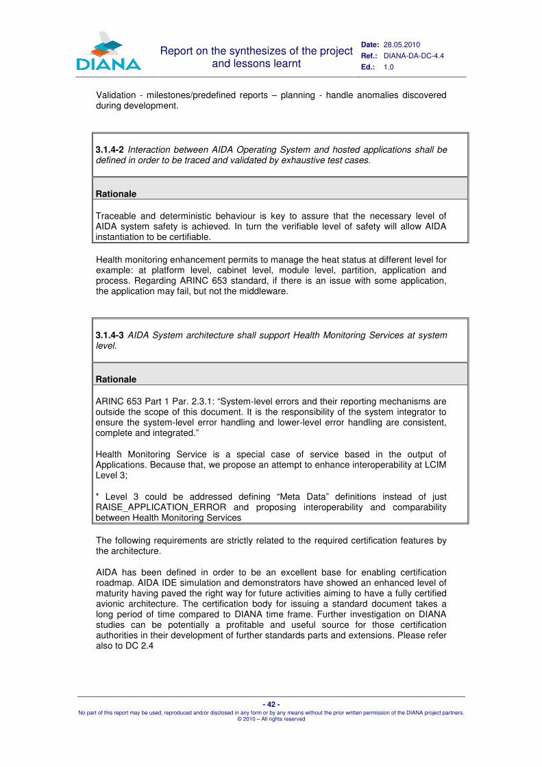
Report on the synthesizes of the project and lessons learnt
Date: 28.05.2010
Ref.: DIANA-DA-DC-4.4
Ed.: 1.0
- 42 - No part of this report may be used, reproduced and/or disclosed in any form or by any means without the prior written permission of the DIANA project partners.
© 2010 – All rights reserved
Validation - milestones/predefined reports – planning - handle anomalies discovered during development.
3.1.4-2 Interaction between AIDA Operating System and hosted applications shall be defined in order to be traced and validated by exhaustive test cases.
Rationale
Traceable and deterministic behaviour is key to assure that the necessary level of AIDA system safety is achieved. In turn the verifiable level of safety will allow AIDA instantiation to be certifiable.
Health monitoring enhancement permits to manage the heat status at different level for example: at platform level, cabinet level, module level, partition, application and process. Regarding ARINC 653 standard, if there is an issue with some application, the application may fail, but not the middleware.
3.1.4-3 AIDA System architecture shall support Health Monitoring Services at system level.
Rationale
ARINC 653 Part 1 Par. 2.3.1: “System-level errors and their reporting mechanisms are outside the scope of this document. It is the responsibility of the system integrator to ensure the system-level error handling and lower-level error handling are consistent, complete and integrated.”
Health Monitoring Service is a special case of service based in the output of Applications. Because that, we propose an attempt to enhance interoperability at LCIM Level 3;
* Level 3 could be addressed defining “Meta Data” definitions instead of just RAISE_APPLICATION_ERROR and proposing interoperability and comparability between Health Monitoring Services
The following requirements are strictly related to the required certification features by the architecture.
AIDA has been defined in order to be an excellent base for enabling certification roadmap. AIDA IDE simulation and demonstrators have showed an enhanced level of maturity having paved the right way for future activities aiming to have a fully certified avionic architecture. The certification body for issuing a standard document takes a long period of time compared to DIANA time frame. Further investigation on DIANA studies can be potentially a profitable and useful source for those certification authorities in their development of further standards parts and extensions. Please refer also to DC 2.4

Report on the synthesizes of the project and lessons learnt
Date: 28.05.2010
Ref.: DIANA-DA-DC-4.4
Ed.: 1.0
- 43 - No part of this report may be used, reproduced and/or disclosed in any form or by any means without the prior written permission of the DIANA project partners.
© 2010 – All rights reserved
3.1.6-1 When industrially available, it shall be possible to develop an AIDA System implementation and hosted applications that will be compliant with currently applicable certification regulations.
Rationale
Today, nobody knows when AIDA will have matured and what regulations will be applicable at that time. This requirement implies that DIANA effort must include a certification for innovations introduced by AIDA.
Otherwise, if an AIDA system cannot be certified, then AIDA is useless.
This means to be certifiable, in principle, with standards such as: DO-178, Federal Aviation Administration (FAA) and European Aviation Safety Agency (EASA) requirements, etc.
For an IMA platform the abstraction level of the applications , their functional independence allow application update without affect hosted application certification credits (reusable software component). Incremental acceptance on the AIDA platform is also obtainable with hosted applications independence on the platform. Hosted Application ( e.g. Air Condition Application or Flight Warning System) have to be designed independent of other applications. Modification of a Hosted Application has to be no impact on other applications, platform resources. ARINC653 suites the mentioned concept.
3.1.6-2 AIDA System shall be compatible with incremental certification of hosted applications.
Rationale
Without incremental certification, IMA, which is a fundamental concept of AIDA, may be cost ineffective.
AIDA System supports other means of testing for verification of low-level requirements. AIDA has been prepared for supporting certification according to DO-178C which is expected to place increase reference to formal methods.
3.2.6-4 AIDA RTOS shall provide DO-178B/C certification evidence supporting IMA deployment.
Rationale
The certification compliance with DO-178B/C is required because AIDA will be used in civil as well as military projects where certification is a mandatory requirement.
System shall cooperating in relation with systems not complaint with same standard certification e.g. means of secondary surveillance, simulators Test-bench , etc.

Report on the synthesizes of the project and lessons learnt
Date: 28.05.2010
Ref.: DIANA-DA-DC-4.4
Ed.: 1.0
- 44 - No part of this report may be used, reproduced and/or disclosed in any form or by any means without the prior written permission of the DIANA project partners.
© 2010 – All rights reserved
Independence and segregation of software components is required to suite different application with different level of certification. This capabilities is very attractive from commercial stakeholders point of view e.g. IFE (In Flight Entertainment). Please refer also to DC 2.4
3.2.6-5 AIDA RTOS shall provide support for applications that are not certified (i.e.: DO-178B Level E).
Rationale
This provision could be a nice to have and could be useful for systems that do not require a certification (i.e.: simulators, emulators, etc.)

Report on the synthesizes of the project and lessons learnt
Date: 28.05.2010
Ref.: DIANA-DA-DC-4.4
Ed.: 1.0
- 45 - No part of this report may be used, reproduced and/or disclosed in any form or by any means without the prior written permission of the DIANA project partners.
© 2010 – All rights reserved
55 WWPP22 AANNDD 33:: AAIIDDAA DDEEVVEELLOOPPMMEENNTT
5.1 The Neutral Execution Environment
An Execution Environment is a software and/or hardware framework which allows software applications to run. Typical execution environment includes hardware, operating system, or programming languages and their runtime libraries.
In practice, the "Neutral Execution Platform" (NEP) is a set of specifications independent from a specific language.
5.1.1 The Runtime
An execution environment is tightly coupled with the programming languages it supports. It aims at abstracting lower software and hardware layers. The approach which has been retained in DIANA is shown on the figure below.
HW
BSP
MOS
A653 AIDA Ext
JVM Middleware
Libraries
Application
Figure 9: Neutral Execution Platform Architecture
Application: AIDA hosted application which calls directly the Lib, the communication library, JVM, the APEX (ARINC 653 parts 1&2) and the AIDA Extensions.
Libraries: Libraries to provide basic abstractions and utilities like the Java collection framework etc.
Middleware: It provides the distribution layer inspired by the OMG Data Distribution System.
JVM: Virtual machine. The Safety Critical Java Technology virtual machine based on the PERC Pico technology.

Report on the synthesizes of the project and lessons learnt
Date: 28.05.2010
Ref.: DIANA-DA-DC-4.4
Ed.: 1.0
- 46 - No part of this report may be used, reproduced and/or disclosed in any form or by any means without the prior written permission of the DIANA project partners.
© 2010 – All rights reserved
A653: The Partition Operating System which contains ARINC 653 Required and Extended APEX services.
AIDA Extensions: AIDA Extensions to ARINC 653 like the logbook.
MOS: Module Operating System which manages and schedules partitions.
BSP: Board Support Package which provides the software layer for driving hardware.
HW: Hardware target.
On the above Figure 9, blue boxes are core of the NEP. Other boxes are made available to applications through a Java language binding that is specified in the scope of AIDA specification.
5.1.2 AIDA Computational Model
5.1.2.1 Program States
During execution, a safety critical program may be in one of the following states: Initialization, Mission, and Recovery. Valid transitions are: Initialization to Mission, Mission to Recovery and Recovery to Initialization. At any time, a program contains one or several active threads of executions, or threads.
During the Initialization phase, a unique thread conventionally referred to as the “main” thread is running. Objects created by the main thread (such as other threads, for example) have the same lifespan as the main thread itself. Newly created threads may not be released before the program switches to the Mission phase.
When switching from the Initialization phase to the Mission phase, threads created during the initialization phase become eligible for execution.
The Recovery phase is the phase triggered by a specific system state change such as the detection of an abnormal situation. The program switches from the Mission phase to Recovery phase to perform user-defined finalization actions and switch to the Initialization phase Persistent objects may be maintained from one mission to another one.

Report on the synthesizes of the project and lessons learnt
Date: 28.05.2010
Ref.: DIANA-DA-DC-4.4
Ed.: 1.0
- 47 - No part of this report may be used, reproduced and/or disclosed in any form or by any means without the prior written permission of the DIANA project partners.
© 2010 – All rights reserved
Program
Initialization
Recovery
Mission
/activate threads
Change mode
Hardware start
Maintain persistentobjects
Bootstrap a main threadwhich performs
objects allocation and initializations
Figure 10: Program States Diagram
5.1.2.2 Concurrency
A safety critical program consists of threads which have the same lifetime as the program lifetime.
Threads of a safety critical program are created during the Initialization phase.
The total number of threads in a program shall be between 1 and a fixed value defined in the Configuration.
Multi-threading shall be started upon the transition from the Initialization to the Mission phase.
Mission threads shall be either periodic or sporadic. They execute the following sequence repeatedly: (i) wait for a periodic or aperiodic event, (ii) perform some actions (computations) in response to this event (said also in short response). The transition from (i) to (ii) represents the thread release. Objects may only be created during the computation sub-phase.
Threads of a safety critical program never terminate in the Mission phase. When the Recovery phase occurs, a given thread preempts all others to perform the recovery actions.
Threads states are the following:
� Dormant: any thread for which resources required for its execution has been allocated and which has not yet started to execute.
� Running: the thread to which the CPU has been assigned. This thread is said the current executing thread.
� Ready: any thread eligible for execution except the current thread.
� Blocked: any thread waiting for a resource.

Report on the synthesizes of the project and lessons learnt
Date: 28.05.2010
Ref.: DIANA-DA-DC-4.4
Ed.: 1.0
- 48 - No part of this report may be used, reproduced and/or disclosed in any form or by any means without the prior written permission of the DIANA project partners.
© 2010 – All rights reserved
� Waiting: any thread waiting for a periodic or sporadic event.
Thread
Ready
Running
Blocked Waitingpreemptionscheduling
Resource request
Triggered eventResource grant
Dormant
Activation
Creation
Figure 11: Thread States Diagram
Note: Released threads consist of the Running, Ready and Blocked threads.
Each thread shall be assigned a fixed priority. This priority may be changed dynamically by the runtime according to the resource access policy (priority inversion avoidance mechanism).
The number of priority levels shall be defined in the Configuration.
Threads shall be scheduled according to the fixed priority preemptive scheduling policy.
Threads scheduling within priority shall be FIFO.
Deadline misses shall be detected by the SCJT virtual machine.
A synchronization mechanism shall be used for sharing data between threads. Blocking (mutual exclusion paradigm) and non-blocking mechanisms may be used.
The mutual exclusion synchronization mechanism shall support the Priority Ceiling Protocol (priority inversion control).
An asynchronous communication mechanism is used to release sporadic threads.
5.1.2.3 Memory
Memory allocations may take place either in a global memory area shared by all threads or in a local memory area owned by and only visible to a specific thread.

Report on the synthesizes of the project and lessons learnt
Date: 28.05.2010
Ref.: DIANA-DA-DC-4.4
Ed.: 1.0
- 49 - No part of this report may be used, reproduced and/or disclosed in any form or by any means without the prior written permission of the DIANA project partners.
© 2010 – All rights reserved
Local memory areas are allocated in the global memory area. Therefore, all the memory required for the program execution from the Initialization phase to the recovery phase is known at the beginning of the Mission phase.
All memory allocations performed in the global memory area shall take place during the Initialization phase.
All allocations performed by a mission thread shall take place in the thread’s local memory area.
The lifespan of an object allocated in the global memory area lasts from the time at which the memory chunk is allocated to the end of the Recovery phase. Note: In practice, the global memory area shall support the same allocation sequence from one program execution to the next. In particular, if a memory allocation sequence (e.g., a worst-case sequence) succeeds for one execution, it shall succeed for any execution.
The lifespan of an object allocated in a thread’s local memory area lasts no more than the duration of the thread’s release. Note: In practice, the thread’s local memory area shall support the same allocation sequence from one release to the next. In particular, if an allocation sequence (e.g., a worst-case sequence) succeeds for one release, it shall succeed for any release.
The amount of allocable memory in the global (or in the local) memory areas shall only depend on the sizes of the allocated memory chunks sizes, and not on the order according to which these allocations were done.
5.1.2.4 Time
A safety critical program shall include a means for representing and following the progress of time.
Time progression shall be monotonic.
Time resolution is defined in the Configuration. The time resolution shall be the nano second and the range shall be between 0 and (2 ** 63)-1.
A safety critical program includes a means for manipulating relative and absolute times.
5.1.2.5 Interoperability
Commands and Data Distribution features as defined in the document DC2.3, see also section 5.2 in the current document.
5.1.3 Java Neutral Execution Platform Implementation � The Safety Critical Java component of the NEP has been implemented with the
PERC Pico technology which provides:
� Annotations (Java meta data) for controlling memory allocation. Safety Critical Java supports memory allocation in two kinds of memory areas. The ImmortalMemory area is used for objects and variables which have the application lifetime. ScopedMemory areas are region-based memory areas and they are used for short-lived objects or variables. Memory allocations in ImmortalMemory and ScopedMemory areas are controlled thanks to PERC Pico annotations and the related tools suite.

Report on the synthesizes of the project and lessons learnt
Date: 28.05.2010
Ref.: DIANA-DA-DC-4.4
Ed.: 1.0
- 50 - No part of this report may be used, reproduced and/or disclosed in any form or by any means without the prior written permission of the DIANA project partners.
© 2010 – All rights reserved
� PERC Pico verifier parses the Java byte-code of the application and checks annotations conform to Safety Critical Java rules (JTOC phase 1).
� If the verifier succeeds the application byte-code is translated into C source files (JTOC phase 2).
� The tool JMELD performs the application classes transitive closure and generates the corresponding Main source file.
� The application executable is built with the traditional C tool chain and the generated C source files. Though this executable is built for a specific platform the Java application does not depend on this platform.
� The Java runtime has been ported to the APEX API, in particular to the following operating systems and target: � SIMA ARINC 653 simulator from SKY (Linux x86). � VxWorks653 from Wind River Systems (VxSim x86 and PowerPC board) � PikeOS APEX personality (PPC Qemu simulator).
� The Initialization/Mission/Recovery phases of the NEP platform have been mapped to APEX START mode/NORMAL mode, and the Recovery phase has been mapped to APEX error handling mechanism.
� In order to ensure a neutral scheduling of threads, PERC Pico has its own scheduler. It supports two kinds of thread, the ones it schedules, and the ones directly scheduled by APEX partition operating system.
5.2 The Interoperability Architecture
5.2.1 Overview
DC2.3 lists a set of services available in an AIDA system. For the implementation of the AIDA simulator, a subset had to be selected. On the other hand, the AIDA simulation must be consistent; the selection, hence, must respect mutual dependencies of services. The following table presents this selection that has been made in the scope of WP2.5:
Component Relies on Part of
Boot Switcher RTOS, SystemManager Multi-Static Reconfiguration
Configuration Manager RTOS, SystemManager,
ModuleManager, HealthMonitor
Multi-Static Reconfiguration
System Manager RTOS, Naming Service (ORB), System Health-
Monitor, ModuleManager
Multi-Static Reconfiguration
Module Manager RTOS, Naming Service
System Manager Multi-Static
Reconfiguration
System Health Monitor RTOS, System Manager N/A
AIDA Broker RTOS, System Health
Monitor AIDA Broker

Report on the synthesizes of the project and lessons learnt
Date: 28.05.2010
Ref.: DIANA-DA-DC-4.4
Ed.: 1.0
- 51 - No part of this report may be used, reproduced and/or disclosed in any form or by any means without the prior written permission of the DIANA project partners.
© 2010 – All rights reserved
Inter-Application Service APEX, AIDA Service Components
AIDA Broker
Configuration Service component APEX, ORB, XML Parser Multi-Static
Reconfiguration
Mode Switcher component APEX AIDA Broker -
Logger component APEX AIDA Logbook
Data Fusion component APEX AIDA Broker
Content Filter component
APEX AIDA Broker
Unit Converter component
APEX AIDA Broker
Java Language Binding JVM, APEX NEP
C Language Binding APEX AIDA Broker, AIDA
Logbook, Multi-Static Reconfiguration
Table 3: AIDA Simulation Components
The selection is based on two parameters:
1. The innovative aspect of the component;
2. The demonstration needs;
In this sense, the AIDA Broker can be seen as one of the core components of the Interoperability Architecture. Its implementation in the AIDA Simulator has therefore been seen as a need.
The Reconfiguration Engine (Multi-Static Reconfiguration) has been identified as an interesting novelty with actual use cases in the avionics domain [28]. The approach that has been followed is different from research work done in other projects, such as SCARLETT, for instance. For these reasons, the AIDA Reconfiguration Engine has been considered an important part of the AIDA Simulator.
AIDA Logbooks are both, interesting and needed for demonstration purposes. AIDA Logbooks demonstrate pluggable platform services in a broader sense and they are needed for location transparency, in case of a reconfiguration that leads to the hosting of applications on different modules. Furthermore, there are of course real-world use cases in the avionics domain.
A component that has been foreseen for implementation in the AIDA Simulator, but was finally not completely implemented, is the System Health Monitor. Despite being an important component in the overall AIDA framework, the System Health Monitor turned out to be rather complex, demanding an implementation, far beyond the time and budget of the DIANA project. However, parts of the System Health Monitor are integrated with the System and Module Manager components of the Reconfiguration Engine: The Module Manager is capable of detecting local faults, indicated, for instance, by the power-up built-in test; the System Manager is capable to reach a consistent view of the health state on system level, i.e. the sum of local health states of all modules in the configuration domain.

Report on the synthesizes of the project and lessons learnt
Date: 28.05.2010
Ref.: DIANA-DA-DC-4.4
Ed.: 1.0
- 52 - No part of this report may be used, reproduced and/or disclosed in any form or by any means without the prior written permission of the DIANA project partners.
© 2010 – All rights reserved
CORBA has been identified as an interesting technology during WP1.2. CORBA should be used to implement application interoperability on component level. This means, Java code could use method invocation of remote objects or even inherit from remote classes, easing the interface generation and interoperability drastically.
In the scope of WP3.3, an integration of CORBA via ARINC 653 ports and channels has been foreseen, using OIS’ CORBA technology ORBexpress. ORBexpress allows such an integration by propagating and receiving CORBA protocol messages through shared memory registers and callback functions that would have been implemented using the ARINC 653 inter-partition services.
As case study for CORBA, a part of the Multi-Static Reconfiguration has been identified. The CORBA experiment has finally not been conducted, due to limitations on time and effort. During middleware implementation and demonstrator integration, a lot of technical issues, concerning low-level integration of components, turned out to be more difficult and, hence, time-consuming than expected. Instead of an actual integration of CORBA and real experiments, a brief comparison between bare ARINC 653 and CORBA has been provided in DC4.3.
CORBA’s Interface Definition Language (IDL) specification provides a higher level specification than ports and channel specifications in ARINC 653 XML files. The IDL specification is shared by client and server whereas in ARINC 653 XML configuration the client XML files contain the client counterpart (ports, channels) of the ARINC 653 server XML files. In ARINC 653, only low-level message-based data exchange is defined. Data exchange via queuing or sampling ports are mere sequences of bytes that must be interpreted and, possibly encoded/decoded on application level. With CORBA application-level semantic is added on platform level. CORBA takes care of the heterogeneity of the systems such as the endianness. CORBA provides an implementation for the location transparency: the CORBA Naming service. It shall be considered that the implemented DDS concept also takes care of the application semantic through the definition of topics and their own readers/writers.
5.2.2 The AIDA Broker
5.2.2.1 AIDA Vision
AIDA Platform Architecture is based on the ARINC 653 concepts, such as resource “partitioning” and on an extension of its foreseen services.
The ARINC 653 APplication EXecutive interface between the application software and the OS defines a set of services which the system shall provide for application software to control, among other aspects, the inter-application communication.
Avionic architectures request a decoupled and fault tolerant communication model in a system that is considered very reliable and static. AIDA architecture foresees an asynchronous and data-centric communication model that supports location transparency when exchanging data among applications. AIDA adopts a publish / subscribe mechanism that includes content filtered support for data exchange. It helps in reducing the impact of software changes at application level.

Report on the synthesizes of the project and lessons learnt
Date: 28.05.2010
Ref.: DIANA-DA-DC-4.4
Ed.: 1.0
- 53 - No part of this report may be used, reproduced and/or disclosed in any form or by any means without the prior written permission of the DIANA project partners.
© 2010 – All rights reserved
Figure 12: communication architecture concepts
From an implementation point of view, inter-application communication is supported by middleware level “data-centric” services (publish and subscribe services) accessing partition memory and distributing data over predefined ARINC 653 channels. In summary, inter-application communication remains based on ARINC 653 ports but a mechanism aimed to enhance location-transparency and to reduce system integrator’s effort is provided.
AIDA vision considers ARINC 653 partitions and ports as the ‘de facto’ software interface among applications in the aeronautic domain. It does not replace ARINC 653 inter partition communication implementations nor proposes dynamic host discovery. Published and subscribed application information are processed off line by AIDA design tool chain, removing the non-deterministic dynamic discovery aspect of publish / subscribe model with side gains in memory and processing footprint. Nevertheless, the level of abstraction in communication is enhanced and additional services devoted to data conditioning and adaptation are provided.
5.2.2.2 The Service concept
AIDA defines its own Service concept: an AIDA Service can be specialized as either Atomic or Compound and may be qualified as composable.
Figure 13: Services dependencies
The provided services may be extended according to integration needs and will deal with all the adaptations needed when integrating existing applications in a new system.

Report on the synthesizes of the project and lessons learnt
Date: 28.05.2010
Ref.: DIANA-DA-DC-4.4
Ed.: 1.0
- 54 - No part of this report may be used, reproduced and/or disclosed in any form or by any means without the prior written permission of the DIANA project partners.
© 2010 – All rights reserved
These services, in the current AIDA simulation include
� content filtering for topics,
� data fusion in many to one communication,
� unit conversion for topic samples
� QoS management (reliability, history, and resource limits).
In the AIDA simulation, all services configuration takes place at design time, in a complete AIDA tool chain, configuration for services would be auto-generated based on ICD definitions.
5.2.2.3 The Broker
The AIDA Broker is part of the AIDA middleware. It is a collection of components that implements the infrastructure to communicate among applications located on different partitions. AIDA Broker supports the “Operational” phase part of data-centric communication, acting as a mediator among the applications.
It decouples application components from the underlying system for what concerns communication and data adaptation, conditioning, aspects.
The Broker has to provide a set of methods to initialize and start all the needed synchronization and communication objects, including ARINC processes and ARINC ports.
In summary, the AIDA BROKER provides a high level of abstraction for interaction among partitions when dealing with both events and data exchange.
The Broker supports Data Read and Data Write activities by means of a dedicated library that has been implemented as part of the demonstration. This library is compliant with a subset of current OMG Data Distribution Service (DDS) Specification, the DCPS layer.
However, huge adaptations and simplifications have been done. Dynamic publication/subscription, dynamic data discovery and type support were not needed or not allowed in our demonstration and have not been implemented. The library allows the “design-time” instantiation of type-specific “Data Writers” and “Data Readers”.
Data types are mapped on the DDS concept of Topic. By definition, a Topic corresponds to a single ICD data type. However, several topics may refer to the same data type. Therefore, a Topic identifies data of a single type, ranging from one single instance to a whole collection of instances of that given type.

Report on the synthesizes of the project and lessons learnt
Date: 28.05.2010
Ref.: DIANA-DA-DC-4.4
Ed.: 1.0
- 55 - No part of this report may be used, reproduced and/or disclosed in any form or by any means without the prior written permission of the DIANA project partners.
© 2010 – All rights reserved
Figure 14: Relation among Topic and Data Type
In AIDA for each data type to be exchanged among applications, a dedicated Topic framework shall be generated.
This framework strongly depends on the data type associated at least in two senses:
� one or more of the parameters of the provided functions belong to the data type;
� the implementation of the functions themselves relies on operations depending in turn on the data type, such as the copy or the comparison.
This dependency introduces a complexity in the framework that had to be reduced in order to make it practically usable. In our plain C implementation, the solution has been the provision of specialized type-dependent functions for each type. The programming overhead has been kept low thanks to the use of proper C macros (in perspective also the AIDA tool chain transformation capabilities to automatically generate topic-dependent functions).
An Application that needs to either publish or subscribe a topic shall define the following components:
� topic_Type declaration of the topic structure and its ancillary types.
� topic_Topic declaration of topic related macros for initialisation
� topic_Sequence declaration of the topic Sequence structure
� topic_Msg defines type of payload to be encapsulated in AIDA msg
� topic_DataReader defines topic data reader
� topic_DataReaderImpl implements topic data reader
� topic_DataWriter defines topic data writer
� topic_DataWriterImpl implements topic data writer
� topic<service_component> defines the requested service components for processing the exchanged topic. This includes data conversion, data fusion and content filtering.
When the applications are integrated in the system being developed the above listed service components shall be available for each topic that is exchanged.
The data/events transmission/reception activity is decoupled from application activity through the deployment of independent processes dedicated to distribution of
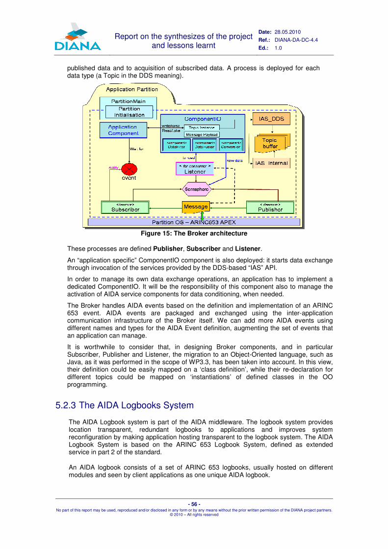
Report on the synthesizes of the project and lessons learnt
Date: 28.05.2010
Ref.: DIANA-DA-DC-4.4
Ed.: 1.0
- 56 - No part of this report may be used, reproduced and/or disclosed in any form or by any means without the prior written permission of the DIANA project partners.
© 2010 – All rights reserved
published data and to acquisition of subscribed data. A process is deployed for each data type (a Topic in the DDS meaning).
Figure 15: The Broker architecture
These processes are defined Publisher, Subscriber and Listener.
An “application specific” ComponentIO component is also deployed: it starts data exchange through invocation of the services provided by the DDS-based “IAS” API.
In order to manage its own data exchange operations, an application has to implement a dedicated ComponentIO. It will be the responsibility of this component also to manage the activation of AIDA service components for data conditioning, when needed.
The Broker handles AIDA events based on the definition and implementation of an ARINC 653 event. AIDA events are packaged and exchanged using the inter-application communication infrastructure of the Broker itself. We can add more AIDA events using different names and types for the AIDA Event definition, augmenting the set of events that an application can manage.
It is worthwhile to consider that, in designing Broker components, and in particular Subscriber, Publisher and Listener, the migration to an Object-Oriented language, such as Java, as it was performed in the scope of WP3.3, has been taken into account. In this view, their definition could be easily mapped on a ‘class definition’, while their re-declaration for different topics could be mapped on ‘instantiations’ of defined classes in the OO programming.
5.2.3 The AIDA Logbooks System
The AIDA Logbook system is part of the AIDA middleware. The logbook system provides location transparent, redundant logbooks to applications and improves system reconfiguration by making application hosting transparent to the logbook system. The AIDA Logbook System is based on the ARINC 653 Logbook System, defined as extended service in part 2 of the standard.
An AIDA logbook consists of a set of ARINC 653 logbooks, usually hosted on different modules and seen by client applications as one unique AIDA logbook.

Report on the synthesizes of the project and lessons learnt
Date: 28.05.2010
Ref.: DIANA-DA-DC-4.4
Ed.: 1.0
- 57 - No part of this report may be used, reproduced and/or disclosed in any form or by any means without the prior written permission of the DIANA project partners.
© 2010 – All rights reserved
An AIDA logbook client issues a request (e.g.: AIDA_WRITE_LOGBOOK) to the AIDA logbook and the same operation is performed in each of the AIDA logbook replicas (e.g.: WRITE_LOGBOOK). The resulting Non-Volatile Memory (NVM) file from each of the replicas should store the same messages, in the same sequence. Therefore a reading operation would return the same message for the client application.
5.2.3.1 Declaring AIDA logbooks
As AIDA logbooks are system wide services; not restricted within the scope of one module, its definitions reflects on several modules. If the AIDA logbook is defined as a set of replicas and clients, spread over N different modules, there are N modules configurations involved in the AIDA logbook realization.
A system level descriptor was developed to specify AIDA logbooks. The AIDA descriptor specifies the location of each logbook replica and logbook clients in terms of the modules that compose the system (or host the AIDA logbook application/subsystem). The listing below illustrates one example of AIDA descriptor:
<System>
<AidaLogbook
LogbookName="AIDA_LOGBOOK"
NBReplicas="3"
NBClients="2"
MaxMessageSize="50"
MaxNBLoggedMessages="60"
MaxNBInProgressMessages="30">
<Replica HostModuleName="R1−Module"
ReplicaName="Replica1">
</Replica>
<Replica HostModuleName="R2−Module"
ReplicaName="Replica2">
</Replica>
<Replica HostModuleName="R3−Module"
ReplicaName="Replica3">
</Replica>
<Client HostModuleName="R1−Module"
ClientPartitionName="Client1">
</Client>
<Client HostModuleName="R2−Module"
ClientPartitionName="Client2">
</Client>
</AidaLogbook>
</System>
The AIDA logbook declared in the example, “AIDA_LOGBOOK”, can store at most sixty messages and has an IN_PROGRESS buffer for thirty messages. Those messages can have at most fifty characters.
The Replica node specifies the module in which a logbook replica is hosted and the ReplicaName attribute is used to derive the name of the partitions that composes the AIDA logbook application in the generated configuration file and source codes.
The value provided for ReplicaName is abstract, in the sense that it does not name an implementation entity, at this level it is used to reference the partitions that comprises the AIDA logbook replicas.
The Client node, on the other hand, specifies the client application host and partition name. The value provided for ClientPartitionName must match an existing partition in the system.
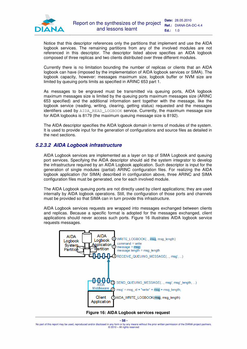
Report on the synthesizes of the project and lessons learnt
Date: 28.05.2010
Ref.: DIANA-DA-DC-4.4
Ed.: 1.0
- 58 - No part of this report may be used, reproduced and/or disclosed in any form or by any means without the prior written permission of the DIANA project partners.
© 2010 – All rights reserved
Notice that this descriptor references only the partitions that implement and use the AIDA logbook services. The remaining partitions from any of the involved modules are not referenced in this descriptor. The descriptor listed above specifies an AIDA logbook composed of three replicas and two clients distributed over three different modules.
Currently there is no limitation bounding the number of replicas or clients that an AIDA logbook can have (imposed by the implementation of AIDA logbook services or SIMA). The logbook capacity, however: messages maximum size, logbook buffer or NVM size are limited by queuing ports limits as specified in ARINC 653 part 1.
As messages to be engraved must be transmitted via queuing ports, AIDA logbook maximum messages size is limited by the queuing ports maximum messages size (ARINC 653 specified) and the additional information sent together with the message, like the logbook service (reading, writing, clearing, getting status) requested and the messages identifiers used by AIDA_READ_LOGBOOK service. Currently, the maximum message size for AIDA logbooks is 8179 (the maximum queuing message size is 8192).
The AIDA descriptor specifies the AIDA logbook domain in terms of modules of the system. It is used to provide input for the generation of configurations and source files as detailed in the next sections.
5.2.3.2 AIDA Logbook infrastructure
AIDA Logbook services are implemented as a layer on top of SIMA Logbook and queuing port services. Specifying the AIDA descriptor should aid the system integrator to develop the infrastructure required by an AIDA Logbook application. Such descriptor is input for the generation of single modules (partial) ARINC configuration files. For realizing the AIDA logbook application (for SIMA) described in configuration above, three ARINC and SIMA configuration files must be generated, one for each involved module.
The AIDA Logbook queuing ports are not directly used by client applications; they are used internally by AIDA logbook operations. Still, the configuration of those ports and channels must be provided so that SIMA can in turn provide this infrastructure.
AIDA Logbook services requests are wrapped into messages exchanged between clients and replicas. Because a specific format is adopted for the messages exchanged, client applications should never access such ports. Figure 16 illustrates AIDA logbook service requests messages.
Figure 16: AIDA Logbook services request
Report on the synthesizes of the project and lessons learnt
Date: 28.05.2010
Ref.: DIANA-DA-DC-4.4
Ed.: 1.0
- 59 - No part of this report may be used, reproduced and/or disclosed in any form or by any means without the prior written permission of the DIANA project partners.
© 2010 – All rights reserved
AIDA logbook service requests are received at the replicas as simple messages. Commands are extracted by the replicas and executed by the logbook application partition. The logbook application partition of an AIDA logbook replica has one specific task: receive client messages, extract the logbook operation and parameters, and execute it.
Part of this partition routine source code is generated by aida_makebooks tool from the information provided by the configuration files. The remaining part of this routine is provided as an operation within aida_logbook.c, a C source code that belong to SIMA distribution.
The AIDA middleware rectangle in the client partitions indicates the implementation of AIDA logbooks API interfacing client application and the SIMA queuing ports. Its source files are at aida_book.c and aida_book.h provided with AIDA logbooks distribution.
aida_makebooks tool uses the AIDA descriptor as input and can generate partial ARINC configurations for the module referenced in AIDA descriptor. Currently this tool cannot generate an entire module configuration but more sophisticated tools should be provided in the future. The partial configuration for the AIDA logbook modules covers the specification of replicas and clients partitions, the AIDA logbook required queuing ports and their channels, and the logbook used by each replica. Nothing outside the scope of the AIDA descriptor is specified by those generated partial configuration.
5.2.3.3 Tool Chain
The tool chain is based on the aida_makebooks tool. aida_makebooks used with different parameters creates configuration and code fragments that can be integrated in the configuration and build chain in an automated or semi-automated way.
In detail, aida_makebooks is used to create the following artefacts:
1. For each module in the system that contains an AIDA logbook replica, the ARINC and SIMA configuration including: � The declaration of a SIMA logbook application partition and system partition; � Two queuing ports (one source and one destination) in each logbook
application partition per AIDA logbook client; � Connections for the logbook application partition to client partitions (local to
the module and to pseudo partitions if remote clients exists); � A logbook declaration named after the AIDA logbook name provided in the
AIDA descriptor (ex: AIDA_LOGBOOK1, AIDA_LOGBOOK2, ...).
2. For each module in the system containing an AIDA logbook client, the ARINC and SIMA configuration including: � The declaration of the AIDA logbook client partition; � One source queuing port to multicast AIDA logbook services requests and
one destination queuing port for each replica (per client partition); � Connections to the logbook replicas (local to the module and to pseudo
partitions for remote replicas).
3. AIDA logbook application partitions source codes for each replica declared;
4. SIMA logbook system partitions for each AIDA logbook replica;
5. AIDA logbook stubs for each AIDA logbook client partition;
6. SIMA logbooks stubs for each replica (pair logbook application partition and logbook system partition);
7. SIMA ports stubs for each logbook application partition;
8. SIMA ports stubs for each logbook client partition.

Report on the synthesizes of the project and lessons learnt
Date: 28.05.2010
Ref.: DIANA-DA-DC-4.4
Ed.: 1.0
- 60 - No part of this report may be used, reproduced and/or disclosed in any form or by any means without the prior written permission of the DIANA project partners.
© 2010 – All rights reserved
For the AIDA Logbook System a C and a Java language bindings are available. The Java binding actually uses the C implementation of this binding by means of the PERC Pico C interface
5.2.4 The AIDA Reconfiguration Engine
The AIDA reconfiguration engine is an AIDA platform service. It is based on the concept of multi-static configurations, i.e., a set of pre-qualified configurations from which the active one will be autonomously selected according to the system health state at system start-up. The configuration selection, of which the determination of the system health state is an essential part, has been defined as a distributed algorithm performed by all modules within the reconfiguration domain. A reconfiguration domain is the set of modules participating in the given reconfiguration. To ensure a consistent view of the system health state by all modules, Byzantine Agreement algorithms have been exploited.
5.2.4.1 Objectives of the AIDA Reconfiguration Engine
The goals of the AIDA Reconfiguration Engine are:
a. Providing a structured set of configurations, such that an AIDA-based system consisting of application components can be used for different purposes without the necessity of introducing any change to the components themselves. Purposes, covered by one system with a multi-static configuration set, may include the following items: � Different modes of operation, e.g. simulation or flight; � Different system scales, e.g.: different aircraft types; � Different business segments, e.g.: passenger transportation, cargo
transportation, military transportation.
b. Providing a structured set of configurations, such that an AIDA-based system is able to automatically degrade gracefully during initialisation in case of faults; faults covered by the multi-static approach share the following characteristics: i. Benign faults; malicious faults are not covered in the scope of the project; ii. Either hardware or software failures within modules (network errors are
attributed to modules); iii. Detectable during definition phase (faults occurring in operation are not
covered by the multi-static approach); iv. Faults that are detected on ground (the algorithm will never be applied
during flight); v. Manifest faults; vi. Faults that show different symptoms to different observers (Byzantine
faults).
This section focuses on the capability set b. Capability set a will be covered by manual configuration. A system that should act as a ground-simulator, for instance, was prepared and tested for this purpose by configuration engineers during design phase. This is a first and the main point of human intervention.
Faults detected during definition phase (by the power-up built-in test, PBIT) may lead to the selection of an alternative, degraded configuration. In this case, fault information and the alternatively selected configuration are presented to the pilot. This is a second point of human intervention. The pilot may reject the elected configuration and select another subset or simply stop processing. The pilot is, of course, not entitled to select a configuration that was excluded by fault detection mechanisms before.

Report on the synthesizes of the project and lessons learnt
Date: 28.05.2010
Ref.: DIANA-DA-DC-4.4
Ed.: 1.0
- 61 - No part of this report may be used, reproduced and/or disclosed in any form or by any means without the prior written permission of the DIANA project partners.
© 2010 – All rights reserved
For the case, the configuration is not changed the pilot does not necessarily need to become active. However, the current configuration and faults that arise should be presented to the pilot. He should have the option to intervene, to stop the system or to select another configuration, but should not be obliged to do so.
To avoid the introduction of a single point of failure during definition phase, fault detection and configuration selection are not performed by a centralised system manager module, but by a distributed system consisting of all modules in the configuration domain, following an interactive consistency protocol. The objective of this protocol is to reduce the probability of a failure of the decision process to a minimum. If a centralised processing unit is used, the failure rate of this unit has to be much lower than any in the controlled system. Depending on the criticality and the number of nodes involved in the system, this failure rate may be beyond of what is achievable. A distributed system turns this relation around: the more units are involved in the processing, the less probable is a failure of the distributed system: single nodes may fail, but not the system they belong to.
An avionics system may be composed of dozens of modules that interoperate with each other directly or indirectly. It is not possible to apply the algorithm to a system consisting of a large number of modules. Furthermore, it is not conceivable to consider an avionics system in an aircraft as a set of homogenous computing modules; Modules have specific IO lines connected to specific devices (sensors, actuators), and therefore it is not possible to allocate functions randomly to modules. Instead, domains of interoperating modules should be defined. A domain is a set of modules that cooperate to determine a configuration. All modules that belong to the same domain have to find an agreement.
To address requirement b.ii, a condition must be met that is defined outside the system and provided to it by the underlying platform, including the OS. How the condition is determined is out of the scope of AIDA.
5.2.4.2 Implementation Strategy
In general, a configuration consists of a set of binaries and configuration data with a main entry point, defining which binaries and configuration files should be loaded into memory. The strategy is thus, to keep all binaries and configuration files needed for all possible configurations in a location that is reachable for the boot loader of the RTOS. When a configuration has been selected by the Configuration Engine and this configuration is different from the current configuration, the main entry point is exchanged (by directly accessing the file system or by requesting a service from file server) and the system is started again. Figure 17 illustrates this approach for a VxWorks platform:
Figure 17: Configuration Application

Report on the synthesizes of the project and lessons learnt
Date: 28.05.2010
Ref.: DIANA-DA-DC-4.4
Ed.: 1.0
- 62 - No part of this report may be used, reproduced and/or disclosed in any form or by any means without the prior written permission of the DIANA project partners.
© 2010 – All rights reserved
The Basic System Configuration (BSC) is a configuration that enables the module to run at least the configuration election in any possible system. As part of the AIDA framework, all valid configurations should meet this requirement. If the BSC is selected as the last configuration that is known to have been applied successfully (= last good), it is probable that it will fit the current system and that a reboot of the system can be avoided. A reboot is necessary only if (new) failures are detected. If the configuration has been changed manually, the BSC will have been set to a new entry point as well and – if no (new) errors occur – no changes are necessary during definition phase.
Application of the reconfiguration and obtaining the PBIT result from the RTOS are functionalities that cannot be established by strict ARINC 653 compliance. To maintain ARINC 653 compliance of applications, those functionalities are implemented in system partitions, separating non compliant and compliant code.
In summary, the following sequence of events results:
Figure 18: Startup Sequence
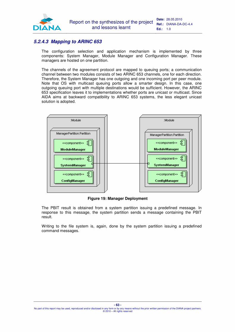
Report on the synthesizes of the project and lessons learnt
Date: 28.05.2010
Ref.: DIANA-DA-DC-4.4
Ed.: 1.0
- 63 - No part of this report may be used, reproduced and/or disclosed in any form or by any means without the prior written permission of the DIANA project partners.
© 2010 – All rights reserved
5.2.4.3 Mapping to ARINC 653
The configuration selection and application mechanism is implemented by three components: System Manager, Module Manager and Configuration Manager. These managers are hosted on one partition.
The channels of the agreement protocol are mapped to queuing ports; a communication channel between two modules consists of two ARINC 653 channels, one for each direction. Therefore, the System Manager has one outgoing and one incoming port per peer module. Note that OS with multicast queuing ports allow a smarter design. In this case, one outgoing queuing port with multiple destinations would be sufficient. However, the ARINC 653 specification leaves it to implementations whether ports are unicast or multicast. Since AIDA aims at backward compatibility to ARINC 653 systems, the less elegant unicast solution is adopted.
Figure 19: Manager Deployment
The PBIT result is obtained from a system partition issuing a predefined message. In response to this message, the system partition sends a message containing the PBIT result.
Writing to the file system is, again, done by the system partition issuing a predefined command messages.

Report on the synthesizes of the project and lessons learnt
Date: 28.05.2010
Ref.: DIANA-DA-DC-4.4
Ed.: 1.0
- 64 - No part of this report may be used, reproduced and/or disclosed in any form or by any means without the prior written permission of the DIANA project partners.
© 2010 – All rights reserved
Figure 20: Module Manager Interoperability
The Module Manager is responsible for the communication with module internal resources, like applications and the system partition. It obtains information from the system stub component, hosted in a system partition (PBIT result, current configuration) and commands it to select the next configuration by manipulating the entry point on the boot device.
The Module Manager publishes the current system operating mode and the selected configuration to all hosted applications. The communication is implemented using ARINC 653 queuing ports and AIDA communication means.
The configuration of the manager partition is linked statically with the application code; this way no additional configuration must be read.
The interfaces between the managers are implemented by APEX blackboards; this is illustrated in Figure 21:

Report on the synthesizes of the project and lessons learnt
Date: 28.05.2010
Ref.: DIANA-DA-DC-4.4
Ed.: 1.0
- 65 - No part of this report may be used, reproduced and/or disclosed in any form or by any means without the prior written permission of the DIANA project partners.
© 2010 – All rights reserved
Figure 21: Component Interaction
Four processes are involved in the configuration election. One, called Proc_ModuleHS, is part of the Module Manager, another, called Proc_Config belongs to the Configuration Manager and two, called Proc_Receiver and Proc_Sender are implemented in the System Manager. The sender and receiver processes are separated to ease the implementation of the different logic of the processes: The receiver is dedicated to processing messages read from n clients; the sender is dedicated to data processing task. Figure 22 shows the interaction of these processes:

Report on the synthesizes of the project and lessons learnt
Date: 28.05.2010
Ref.: DIANA-DA-DC-4.4
Ed.: 1.0
- 66 - No part of this report may be used, reproduced and/or disclosed in any form or by any means without the prior written permission of the DIANA project partners.
© 2010 – All rights reserved
Figure 22: Process Interaction
Proc_ModuleHS retrieves the current configuration and, if the aircraft has not yet started taxiing, it puts it to the blackboard BB_Config; then it retrieves the PBIT result and puts it into the blackboard BB_ModuleHS. Afterwards, it waits blackboard BB_Config to be cleared and then for blackboard BB_Config to be written by the ConfigManager. If the aircraft is already in operating mode, it simply starts with the current configuration. In this case, it either comes too late and will be ignored by other modules or the module was reinitialised during flight.
When the blackboard BB_Config has been written, the configuration election process has terminated. Proc_ModuleHS checks the new configuration. If it is the NULL configuration, the module is shutdown. Otherwise, it is compared to the current configuration; if it is not equal, the process waits for the pilot confirmation, a message coming through a queuing port (which is left out for clarity reasons). If the pilot rejects this confirmation, the module shuts down.
After receiving the pilot confirmation, the new configuration is set, calling the SystemStub, and the module is rebooted. Otherwise, OPERATION is published as new operating phase. At the end, the process stops itself.
Different solutions have been chosen on the AIDA demonstrators to implement the shutdown and reboot mechanisms. For more details, please refer to [17] and [19].
5.2.5 The AIDA Interface Control Document
Generally, ICD are used to describe interface of a system, component, service, application, etc. in order to support its integration with other parts of a system. The focus is on the possible interactions of the considered element with its environment, not on its internals.
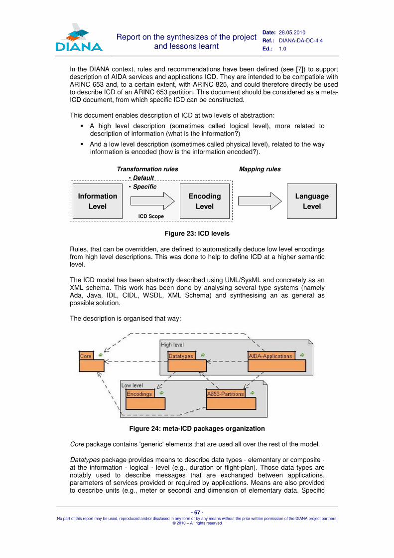
Report on the synthesizes of the project and lessons learnt
Date: 28.05.2010
Ref.: DIANA-DA-DC-4.4
Ed.: 1.0
- 67 - No part of this report may be used, reproduced and/or disclosed in any form or by any means without the prior written permission of the DIANA project partners.
© 2010 – All rights reserved
In the DIANA context, rules and recommendations have been defined (see [7]) to support description of AIDA services and applications ICD. They are intended to be compatible with ARINC 653 and, to a certain extent, with ARINC 825, and could therefore directly be used to describe ICD of an ARINC 653 partition. This document should be considered as a meta-ICD document, from which specific ICD can be constructed.
This document enables description of ICD at two levels of abstraction:
� A high level description (sometimes called logical level), more related to description of information (what is the information?)
� And a low level description (sometimes called physical level), related to the way information is encoded (how is the information encoded?).
ICD Scope
Information
Level
Encoding
Level
Transformation rules
• Default
• Specific
Language
Level
Mapping rules
Figure 23: ICD levels
Rules, that can be overridden, are defined to automatically deduce low level encodings from high level descriptions. This was done to help to define ICD at a higher semantic level.
The ICD model has been abstractly described using UML/SysML and concretely as an XML schema. This work has been done by analysing several type systems (namely Ada, Java, IDL, CIDL, WSDL, XML Schema) and synthesising an as general as possible solution.
The description is organised that way:
Figure 24: meta-ICD packages organization
Core package contains 'generic' elements that are used all over the rest of the model.
Datatypes package provides means to describe data types - elementary or composite - at the information - logical - level (e.g., duration or flight-plan). Those data types are notably used to describe messages that are exchanged between applications, parameters of services provided or required by applications. Means are also provided to describe units (e.g., meter or second) and dimension of elementary data. Specific
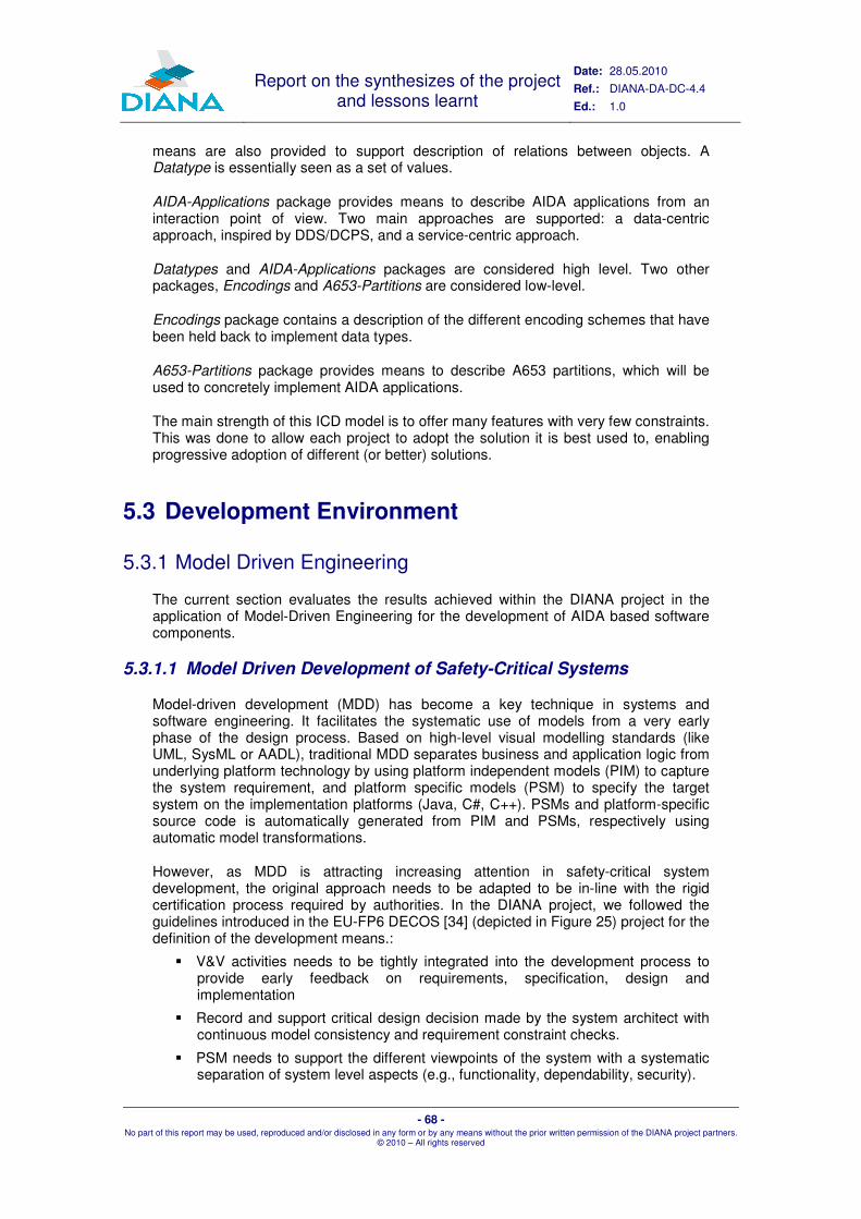
Report on the synthesizes of the project and lessons learnt
Date: 28.05.2010
Ref.: DIANA-DA-DC-4.4
Ed.: 1.0
- 68 - No part of this report may be used, reproduced and/or disclosed in any form or by any means without the prior written permission of the DIANA project partners.
© 2010 – All rights reserved
means are also provided to support description of relations between objects. A Datatype is essentially seen as a set of values.
AIDA-Applications package provides means to describe AIDA applications from an interaction point of view. Two main approaches are supported: a data-centric approach, inspired by DDS/DCPS, and a service-centric approach.
Datatypes and AIDA-Applications packages are considered high level. Two other packages, Encodings and A653-Partitions are considered low-level.
Encodings package contains a description of the different encoding schemes that have been held back to implement data types.
A653-Partitions package provides means to describe A653 partitions, which will be used to concretely implement AIDA applications.
The main strength of this ICD model is to offer many features with very few constraints. This was done to allow each project to adopt the solution it is best used to, enabling progressive adoption of different (or better) solutions.
5.3 Development Environment
5.3.1 Model Driven Engineering
The current section evaluates the results achieved within the DIANA project in the application of Model-Driven Engineering for the development of AIDA based software components.
5.3.1.1 Model Driven Development of Safety-Critical Systems
Model-driven development (MDD) has become a key technique in systems and software engineering. It facilitates the systematic use of models from a very early phase of the design process. Based on high-level visual modelling standards (like UML, SysML or AADL), traditional MDD separates business and application logic from underlying platform technology by using platform independent models (PIM) to capture the system requirement, and platform specific models (PSM) to specify the target system on the implementation platforms (Java, C#, C++). PSMs and platform-specific source code is automatically generated from PIM and PSMs, respectively using automatic model transformations.
However, as MDD is attracting increasing attention in safety-critical system development, the original approach needs to be adapted to be in-line with the rigid certification process required by authorities. In the DIANA project, we followed the guidelines introduced in the EU-FP6 DECOS [34] (depicted in Figure 25) project for the definition of the development means.:
� V&V activities needs to be tightly integrated into the development process to provide early feedback on requirements, specification, design and implementation
� Record and support critical design decision made by the system architect with continuous model consistency and requirement constraint checks.
� PSM needs to support the different viewpoints of the system with a systematic separation of system level aspects (e.g., functionality, dependability, security).

Report on the synthesizes of the project and lessons learnt
Date: 28.05.2010
Ref.: DIANA-DA-DC-4.4
Ed.: 1.0
- 69 - No part of this report may be used, reproduced and/or disclosed in any form or by any means without the prior written permission of the DIANA project partners.
© 2010 – All rights reserved
� Finally, support code synthesis not only for source code but also system configuration, certification and documentation artefacts.
How these considerations were applied for the definition of the AIDA Model–Driven Development Means of configuration and behavioural artefacts are detailed in DIANA_DC3_1. Section 5.3.1.2 gives a brief overview on the achieved results, while Section 5.3.1.3 summarizes our evaluation of the proposed development means with a focus on gaps and directions for future research.
Figure 25: MDD process for Safety Critical Development
5.3.1.2 The AIDA Development means
The DIANA project aims at experimenting with model based technologies for the design, development and deployment of mission critical software components in the avionics domain. Within the ADIA development means we primarily focused on following two critical areas::
� Architectural modelling: The aim is to support the architectural design and development of AIDA based software components starting from high-level platform independent languages like Matlab Simulink and through consequent steps of refinement generate a Platform Specific representation that can serve as the input for the configuration generation.
� Behavioural modelling: Providing means for aiding the design and validation of the internal structure of AIDA applications. The aim is to support both code synthesis from high-level description of the application logic and additionally allow verification and validation techniques like model checking and model based test case generation.
A high-level overview of the developed tool-chain is depicted in Figure 26.

Report on the synthesizes of the project and lessons learnt
Date: 28.05.2010
Ref.: DIANA-DA-DC-4.4
Ed.: 1.0
- 70 - No part of this report may be used, reproduced and/or disclosed in any form or by any means without the prior written permission of the DIANA project partners.
© 2010 – All rights reserved
Legend
Traceability
Verification&
Validation
PIM-PSM
Mapping
Platform
Desc.
Model
ICDVxWorks
653 Config
Deployment
Executable
PIADLBehavioral
State
Machines
Requirements
SC-Java
Source
Code
AIDA
Logbook
Config
AIDA PSM
UPPAAL
Behaviour
Simulation
UPPAAL
Model
Checking
MOGENTES
Model-Based
Test Generation
KEY-based
Memory footprint
Analysis
Simulink
Model
Integration M
odel
Traceability
file
Specification (PIM)
Design (PSM)
Implementation
Deployment
Figure 26: Overview of the AIDA Model Based Development Process
5.3.1.2.1 Architectural Modelling: PIM-to-PSM mapping
In our approach, the high-level architectural view of the system is captured by a Platform Independent Model (PIM). In order to support a variety of existing front-end modelling tools and languages (like Matlab Simulink or SysML), we internally use a unified Platform Independent Architecture Description Language (PIADL) for recording architectural details (such as the list of functionalities, messages, etc.) by extracting relevant information from supported COTS models (e.g., Simulink). From the PIADL through a complex mapping process, using the available platform resources defined in Platform Description, the precise low-level details of a specific configuration for the ARINC653 platform are captured by the AIDA Platform Specific Model (PSM). Finally, from the AIDA PSM configuration artefacts are generated.
Mapping the PIM to the PSM is handled by a complex, interactive model transformation process. This needs to bridge a large abstraction gap, where critical design decisions made by the system architect, which cannot be automated.
Therefore, we support the system architect by subdividing the mapping process into well-defined design steps and precisely define the contracts, interactions and interfaces of each step. Individual design steps are then organized into complex workflow-driven model transformation chains, which are closely aligned with the designated development process followed by the airframer. In order to assist the system architect, our framework guarantees that a certain design step can only be

Report on the synthesizes of the project and lessons learnt
Date: 28.05.2010
Ref.: DIANA-DA-DC-4.4
Ed.: 1.0
- 71 - No part of this report may be used, reproduced and/or disclosed in any form or by any means without the prior written permission of the DIANA project partners.
© 2010 – All rights reserved
started if all prerequisite steps are successfully completed. Our framework is easily customizable to incorporate additional design steps, if required.
As the AIDA PSM already captures all design decisions for developing a configuration, it enables to automatically generate the real artefacts of configuration tables by dedicated code generators. Our approach generates the following configuration tables: (i) standard and VxWorks specific ARINC 653 Module, Partition and Application descriptions (ii) Interface and message descriptions captured by the ICD and (iii) AIDA middleware configuration that is AIDA Logbook configuration in our case.
Additionally, as an essential requirement of DO-178B certification continuous traceability has been carried out from the high-level requirements to the deployed applications. In case of the design phase we used (i) inter-model traceability based on the Integration Model that keeps track of all manipulations done during the PIM-PSM mapping process and (ii) model-to-configuration traceability with XMI files connecting generated configuration elements to their corresponding model entities.
5.3.1.2.2 Behavioural modelling: Dynamic Modelling with State Machines
In our approach, behavioural modelling of tasks (applications) were carried out using UML state charts. This formalism enables the visual modelling of event driven finite state-transition systems in a hierarchical way featuring user-friendly presentation, rich modelling toolset and the wide set of popular modelling environments. Unfortunately the application of UML state machines also implies some drawbacks e.g., (i) the standard does not define an unambiguous formal semantics for state models and (ii) the standard does not provide effective means for the specification of activities associated to states and transitions. In order to overcome these weaknesses we proposed the following solutions:
(i) We proposed the application of a previously defined formal operational semantics for UML state machines based on Kripke Transition Systems (KTS). UML state machines can be automatically transformed to the KTS representation, whose locations correspond to configurations of the state machine and edges represent entire steps between configurations of the state machine involving the event that triggered the step and the complex activity structure to be performed.
(ii) In order to enable the user to embed the specification of activities in the UML model we defined an executable UML sub-language called Activity and Guard Specification Language AGSL [35]. AGSL code fragments can be attached to any points of the model where activities are used providing a target independent, programming language like specification formalism.
The solid foundations provided by the formal semantics and the AGSL language enabled the straightforward development of simulation, code synthesis, model checking and test generation tools both built on the same core enabling convenient model interchange and integration to the Eclipse platform.
5.3.1.2.3 V&V activities
As described in [15] (and depicted in Figure 26) parallel to the Development process the Verification and Validation activities are also executed. Keeping the design and verification aspects tightly synchronized enables to use V&V results for model/code refinement as close as possible to the corresponding model/code development time. In the context of DIANA we defined the following V&V activities:

Report on the synthesizes of the project and lessons learnt
Date: 28.05.2010
Ref.: DIANA-DA-DC-4.4
Ed.: 1.0
- 72 - No part of this report may be used, reproduced and/or disclosed in any form or by any means without the prior written permission of the DIANA project partners.
© 2010 – All rights reserved
� Based on the State Machines defining the behaviour of applications the use of the UPPAAL framework enables to (i) validate certain aspects of the application logic by model checking its underlying Kripke structure and also (ii) simulate the modelled system. Additionally, the use of State Machines for the definition of applications enables to generate test-cases based on the results of the EU-FP7 MOGENTS [33] project.
� Static analysis of source code also plays an important role in the V&V activities as it allows early feedback both on hand-coded and generated code. In the context of the DIANA project a static analysis tool (based on the KEY system [26]) for the validation of memory layout of Safety Critical Java applications was implemented and evaluated (see chapter 5.3.2.3).
As a summary, our framework applies model-driven development techniques to support the systematic design of ARINC 653 configuration tables with (i) a complete end-to-end traceability from the high-level models down to the generated artefacts, (ii) tightly integrated V&V activities for early error detection and (iii) model based on-the-fly validation of design requirements during the development process.
5.3.1.3 Conclusion and Future Directions
In the context of the project we have demonstrated that Model-Driven Engineering can be effectively applied for the development of safety-critical systems. Additionally, we have identified (see in [8]) key certification issues of MDE that needs to be further examined in order to achieve the maturity level required by certification authorities.
However, during the evaluation of the proposed technologies we have encountered gaps and shortcoming that point to future work and new research directions:
� One key issue for the success of MDE in the safety-critical domain is the certification of model transformation. MT serves as the backbone of almost all model based technologies from code and model synthesis through model validation techniques to simulation. Up to date many work has been done regarding the V&V of transformations, however, certification issues were rarely covered in recent publications.
� As development of safety-critical system usually requires large number of developers the need for advanced collaborative support for the definition models like versioning, distributed development, access control etc. is becoming a key question.
� MDE promises an easier way of integrating various tools based on a common integrated model (or model bus) that allows their input and output models of the various tools to be treated in a common way. Additionally, it can give support to model based traceability a common requirement by various certification authorities.
� Model-based analysis for early verification and validation. One of the main problems with current approaches that they do not scale up to real size problems. One promising approach is the use of and compositional techniques (e.g., abstraction, hierarchical modelling) to break down state spaces.
� Define a unified approach (called Model transformation chains) for tool integration and tool development with interactive and automated model transformation steps aiming to reduce the cost of software tool qualification.

Report on the synthesizes of the project and lessons learnt
Date: 28.05.2010
Ref.: DIANA-DA-DC-4.4
Ed.: 1.0
- 73 - No part of this report may be used, reproduced and/or disclosed in any form or by any means without the prior written permission of the DIANA project partners.
© 2010 – All rights reserved
5.3.2 Formal Methods
Several application areas of formal methods in the context of Avionics software were investigated within the scope of the DIANA project. First of all there were two practical applications of formal methods to software developed in the course of the project:
1. Source code specification and verification techniques were evaluated on the Environmental Control System-demonstrator.
2. On a more abstract level, the Byzantine agreement protocol was verified using Event-B [31] and the Rodin tool.
Both applications showed that formal verification of safety critical avionics software can be feasible on the source code, as well as on a more abstract protocol description level.
Also basic research in the field of verification of worst-case memory consumption was done. One outcome of this is a design-by-contract-based approach for specifying the worst-case memory consumption of Java programs. This approach was adapted to the memory model of PERC Pico, as this is the safety-critical Java dialect employed in DIANA. The discussion on the upcoming DO-178C standard was actively followed including the participation in one working group 71 (the working group responsible for defining the formal methods-supplement of DO-178C) meeting. In addition, the formal verification of model transformations was investigated in cooperation with Budapest University.
5.3.2.1 Environmental Control System Case Study
A case study for evaluating the suitability of formal source code specification and the applicability of static analysis tools to aeronautical software was performed in work package 4.3. As target application the Environmental Control System was used. The code was implemented in (PERC Pico-) Java, formally specified with JML [30] and statically checked with ESC/Java2 [29]. As a result of the performed experiments the entire implementation of the so-called Zone- and Pack-controllers representing the core functionality of the ECS and consisting of 12 classes and interfaces was proven to be correct with respects to
1. the specified frame conditions. This means that the controllers can never exhibit any unspecified side effects;
2. the implicit specification stating absence of RuntimeExceptions.
This demonstrates the suitability of static software analysis for Java code that is encapsulated to an extend that it does not depend on any insufficiently specified libraries. It must, however, be taken into account that PERC Pico's region-based memory model is not supported by ESC/Java2 which is a potential source for program bugs not covered by the verification results.
5.3.2.2 Byzantine Agreement Protocol
As reported in [28] and [21] the Byzantine Agreement Protocol employed as part of the multi-static reconfiguration mechanism was formally verified using Event-B [31] and Rodin. The formal verification efforts performed with Rodin led to a better understanding of the Byzantine Agreement protocol and an optimized version of it (described in [28]) suited to the requirement of the multi-static configuration approach developed in the DIANA project. Recapitulating one can say that Event-B and Rodin showed to be useful for verification attempts on an abstract protocol level, however, Rodin's prover support, especially for arithmetics, needs to be improved.

Report on the synthesizes of the project and lessons learnt
Date: 28.05.2010
Ref.: DIANA-DA-DC-4.4
Ed.: 1.0
- 74 - No part of this report may be used, reproduced and/or disclosed in any form or by any means without the prior written permission of the DIANA project partners.
© 2010 – All rights reserved
5.3.2.3 Memory Contracts
An approach for specifying and verifying the worst-case heap memory usage (WCMU) of Java programs was developed within the scope of work packages 2.4 and 3.4. A comprehensive overview of this approach can be found in [26]. Specification of WCMU is done in a JML-like [30] notation and follows the design-by-contract paradigm. Formal Verification of memory contracts is done on the level of method implementation level leveraging method contracts for approximating the effect of method invocations for achieving modularity and thus scalability of the approach. The approach was implemented in the KeY system [32] a software verification tool for Java.
5.3.2.4 PERC Pico
The approach for specifying and verifying the WCMU of Java programs was adapted (see [26]) to PERC Pico's region-based memory model. The intention of this effort was to obtain a technique for verifying WCMU of PERC Pico programs which is more powerful than PERC Pico's built-in static analysis. This technique could then be used to verify user-provided memory consumption annotations which are required in cases in which PERC Pico is not able to determine the memory consumption automatically. This approach which was also implemented in the KeY system was, however, not used in the case study mentioned in Section 4.1.5 due to floating point arithmetics frequently occurring in the code and KeY's lacking support for this.
5.3.2.5 Formal Verification of Model Transformations
In a joint effort with Budapest University, the formal verification of model transformations was investigated. The attempted approach to apply source code verification techniques to Java source code generated by VIATRA turned out to be infeasible for the kind of code generated. One reason was the deep nesting level of loops (in the relatively simple example we considered for our experiments we already had to deal with seven-fold nested loops) which could not be handled by the employed verification tool and necessitated refactoring of the code before verification could be started. A lesson learned from these experiments was that verification of model transformation should preferably attempted on a more abstract representation of the transformation than on the generated source code.
5.3.3 Implementation of the Development Tool Chain in the AIDA Simulator
During simulation and demonstrator development, available COTS have been used. It was hence necessary to map AIDA development means onto available tools. The following figure describes the resulting tool chain and uses the mapping to the SIMA ARINC 653 simulator as an example:

Report on the synthesizes of the project and lessons learnt
Date: 28.05.2010
Ref.: DIANA-DA-DC-4.4
Ed.: 1.0
- 75 - No part of this report may be used, reproduced and/or disclosed in any form or by any means without the prior written permission of the DIANA project partners.
© 2010 – All rights reserved
Figure 27: Mapping of the AIDA Development Environment to the SIMA Tool Chain
On platform level two artefacts are created by engineers: The Platform Independent Model (PIM) and the Service Definition Descriptor for Logbooks. Both artefacts are native AIDA elements, defined in the scope of the project.
From PIM and Logbooks SDD some configuration elements are generated, namely ports and connections that enter the ARINC 653 configuration and the SIMA specific configuration. The generation in the case of logbooks is fully automated, the mapping is a manual engineering process assisted by the mapping tool. From the mapping,
Report on the synthesizes of the project and lessons learnt
Date: 28.05.2010
Ref.: DIANA-DA-DC-4.4
Ed.: 1.0
- 76 - No part of this report may be used, reproduced and/or disclosed in any form or by any means without the prior written permission of the DIANA project partners.
© 2010 – All rights reserved
ARINC 653 configuration artefacts are generated automatically. Note that an additional local, template-based tool chain has to be defined to automate the integration of aida_makebooks and the PIM mapping process.
As mentioned already in DC3.1, the services are already considered in the AIDA modles and can be identified in the mapping editor. However, the necessary output is not yet generated automatically; to fill this gap, the aida_makebooks tools has been developed, based on configuration and code generators already available in the SIMA tool chain.
The configuration files have module scope, but no module-wide artefacts are generated from them in the case of the SIMA tool chain. Instead, the process enters directly the application (i.e. partition) level.
The aida_makebooks tool is still relevant for generating logbook middleware stubs and logbook server stubs from the Logbook SDD. All communication-relevant artefacts are processed by makeports, a SIMA-specific tool that generates stubs for initialising the ports within the partitions.
The application-specific C code is generated by PERC Pico tools jtoc and jmeld. For applications, written directly in C, this code is typically generated by human engineers or code generators outside the AIDA tool chain in the strict sense, such as SIMULINK.
Now, the tool chain flows into the standard GNU tool chain: The C files are compiled with GCC and linked with LD, adding a set of libraries, coming from SIMA (the partition operating system), PERC Pico (the Java Virtual Machine) and AIDA (Java APEX API, Logbooks middleware, Broker middleware and so on).
The lower part of the process, the partition level, is iterated over all partitions in the system. Note that for multi-static configurations, the process has to be additionally iterated, on platform level, over all configurations. This step is not shown in Figure 27 to keep the diagram readable.
5.4 Certification Aspects
Initial planning of activities related to certification covered most DIANA's aspects. It was decided to adopt a pragmatic approach by focusing on a reduced set of four topics, the first three being directly addressed by DO-178C revision committees:
1. Java for safety critical embedded systems (object-oriented languages)
2. Model transformations (model driven engineering)
3. Formal methods
4. Impact of DIANA architecture and middleware on certification.
A detailed synthesis of work achieved in this area is given in [8].
5.4.1 Use of Java for Safety Critical Embedded Applications
The Java platform is a key component of the “Neutral Execution Platform” proposed by DIANA. It appears that no DO-178 recommendation strictly forbids any of the core features of the Java language and platform, such as object-orientation or dynamic memory allocation, for instance. The issue is more related to the effort that would be required to demonstrate compliance with the DO-178 objectives. Current drafts of DO-178C supplements even explicitly mentions the use of dynamic memory or virtual
Report on the synthesizes of the project and lessons learnt
Date: 28.05.2010
Ref.: DIANA-DA-DC-4.4
Ed.: 1.0
- 77 - No part of this report may be used, reproduced and/or disclosed in any form or by any means without the prior written permission of the DIANA project partners.
© 2010 – All rights reserved
machines. Most important risks associated to the use of Java have been identified. The use of PERC Pico was studied to see how this platform could reduce those risks, notably those related to memory allocation and time determinism. DIANA contributed to the maturation of PERC Pico.
PERC Pico annotation system is characterized by several features:
� It assures that scope memory relationship constraints associated with all arguments passed to a method are clearly identified so that all users of the method understand the constraints required for reliable execution of the method.
� It assures that all arguments passed to a method satisfy the scope memory relationship constraints associated with the invoked method.
� It reduces the syntactic clutter associated with entering and exiting scopes and establishing scope sizes, with the objective of making code more readable and more maintainable and reducing the opportunity for human error.
� It enables modular composition and maintainability of software components.
As PERC Pico gives solutions to mitigate some of the risks associated to Java, the next objective was to check whether using PERC Pico would bring its own risks. This analysis was quite shallow and limited, but it appears that the Java to C translator behaves deterministically. Further analyses are necessary, notably to check translation of more code patterns, to check runtime checks that may be suppressed thanks to code analysis, or to check compliance of the generated code with coding standards.
An experiment was done to convert a standard Java code to PERC Pico and observe the issues. Result is of course dependent on the initial code, but it appears that:
� Modifying an existing application – i.e. the addition of the appropriate annotations and the refactoring required to get a consistent memory allocation scheme that will pass PERC Pico verifications – is complex and expensive, in particular without support from the environment.
� Some had-hoc rules have been adopted, but no clear and rigorous guidelines for the usage of PERC Pico memory annotations could be defined.
These conclusions may seem negative, but one should keep in mind that the PERC Pico annotations have not been defined to facilitate the developer work, but with the hope that they would reduce future maintenance efforts.
Qualification of PERC Pico runtime, libraries and tools has not been investigated in details since the product is still in active development. More generally, the demonstration of compliance with the DO-178 would require industrial activities that are neither compatible with the nature of a research project, nor compatible with the effort allocated to the task.
Finally, it appears that very few tools necessary to support a DO-178 compliant application with Java are specific to that language. The main remaining issue concerns tools, such as PERC Pico, that claim to ease compliance with DO-178 but that are not (yet) used for large scale development.
5.4.2 Model Transformations
The usage of model transformation for the development of certified systems raises two complementary questions:

Report on the synthesizes of the project and lessons learnt
Date: 28.05.2010
Ref.: DIANA-DA-DC-4.4
Ed.: 1.0
- 78 - No part of this report may be used, reproduced and/or disclosed in any form or by any means without the prior written permission of the DIANA project partners.
© 2010 – All rights reserved
� Are model-driven development practices compatible with DO-178 objectives? In particular: Are we still able to demonstrate the traceability between the numerous artefacts generated during the transformation process? After a model modification, do we control the impact of the modification?
� How can we take benefits of those practices to simplify development activities? In particular, how can we ensure that a property demonstrated to be true at an abstract level (where it is easy to verify) will still hold in the final product (or in some artefact at the latest in the development process)?
In the DIANA context, focus was put on the latter question.
Activities related to transformations were based on the Viatra2 framework. However, no work has been carried out to prove that this framework can be considered as formal. The general problem of verifying and validating a graph-based model transformation has been addressed and a survey of existing techniques for the formal verification of model transformations has been produced. Handling of traceability between an abstract representation of a model and a concrete - textual or graphical - representation has been addressed and results have been integrated to the Viatra2 framework.
An overall model transformation process has also been defined and applied to DIANA.
5.4.3 Formal Methods
As indicated above, future DO-178C standard will include a supplement dedicated to formal methods. This reflects a clear trend where formal methods leave the research area to reach the industry. Within DIANA, we targeted two general objectives:
1. Let industrial partners get acquainted with those particular techniques.
2. Support formal specifications and, if possible, formal verification of properties that are difficult to handle using "traditional" verification techniques.
An experiment has been carried out with OCL to formalize the constraints a user of an API has to comply with. Results of this experiment are somewhat limited, as other choices (such as JML) might have been more appropriate, nevertheless OCL has been effectively used to specify configuration constraints on IMA.
The contract concept has also been studied. Possible roles and benefits of contracts usage in software development, incremental certification and in DO-178 compliant processes have been analyzed. The impact on tools qualification has also been addressed. Concretely, analyses have been done using Frama-C environment, on C code, but results are quite easily applicable to other languages, notably Java.
Usage of contracts for memory allocation has also been undertaken. Several results were obtained:
� New constructs have been added to JML to support formal specification of memory usage in RTSJ.
� Proof obligations about memory can be generated and discharged automatically by the KeY deductive system. Proofs rely on the formalization of Java sequential programs in the Java DL dynamic first order logic.
� This is applicable to any Java code complying with the “Key Safety Critical Java profile” (KeYSCJ), which imposes a few restrictions about memory usage, finalization, and static initialization. It is worth noting that those constraints are “much less restrictive” than other safety critical Java profiles.

Report on the synthesizes of the project and lessons learnt
Date: 28.05.2010
Ref.: DIANA-DA-DC-4.4
Ed.: 1.0
- 79 - No part of this report may be used, reproduced and/or disclosed in any form or by any means without the prior written permission of the DIANA project partners.
© 2010 – All rights reserved
� A formalization of PERC PICO memory usage in order to support the verification of scope sizes was also developed. This is very interesting since, if the PERC PICO compiler already uses abstract interpretation to verify that an annotated PERC Pico program complies with its annotations concerning referential integrity, properties concerning memory consumption are not (yet) verified automatically.
5.4.4 Architecture and Middleware
DIANA was aimed at introducing technologies and mechanisms to improve airborne computing architectures and simplify software development. As any change in usual practices, all of them were expected to impact the certification process, either positively or negatively. WP2.4 was aimed at analyzing this impact concurrently with the design process of DIANA infrastructure, so as to determine the design choices that would maximize the positive impact (e.g., reduce verification costs) and minimize the negative impact (e.g., make the technology acceptable).
The main mechanisms designed were:
� A Data Centric approach, through the implementation of a Data Distribution Service
� The capability to support multi-static reconfiguration using a distributed algorithm to select the applicable configuration
These improvements should have possibly deserved a deeper analysis since they represent major changes, nevertheless the high level analysis performed shows that the DIANA architecture seems to be appropriate to support a certifiable platform, as well, an incremental acceptance approach as prescribed by the RTCA DO-297 [24]. Surely, many aspects that are programme specific have to be explored more in detail (along with Authorities support) in the dedicated and project specific documentation.
Again, the discussion regarding adequacy of RTCA DO-297 [24] to support the certification of integrated and reconfigurable platforms is still open. As pointed out in DC2.4-5 [13], DIANA faced the fact that regulations and guidance for IMA certification are not completely clear; many technical and process related issues are still under discussion. All these issues have consequences on each specific project and it is thus difficult to perform a deeper analysis within the framework of a research project as DIANA.
Report on the synthesizes of the project and lessons learnt
Date: 28.05.2010
Ref.: DIANA-DA-DC-4.4
Ed.: 1.0
- 80 - No part of this report may be used, reproduced and/or disclosed in any form or by any means without the prior written permission of the DIANA project partners.
© 2010 – All rights reserved
66 WWPP44:: AAIIDDAA EEVVAALLUUAATTIIOONN SSYYNNTTHHEESSIISS
6.1 Demonstration Approach
In WP 4 two demonstrator environments are setup in which the AIDA components are integrated with an avionics application. One demonstrator is located at Embraer and hosts the Flight Warning System (FWS) application developed by Thales, the second one is located at NLR and runs the Environmental Control System (ECS) application developed by NLR in MATLAB/Simulink and ported to Java by the University of Karlsruhe and NLR. The objective of the demonstrators is to test and benchmark the AIDA components developed in WP 3. The focus is on demonstration of AIDA services and not on formal verification of requirements. The objective is to perform a proof of concept, a first level assessment to show the feasibility of the AIDA concepts.
The first step in WP 4 was to define a test plan (WP 4.1), the test plan selects the requirements and specifications which are considered the core of the AIDA concept and outlines the steps that need to be taken to verify the requirements. Secondly, a plan for integration of the different AIDA components was setup. For the ECS demonstrator this concerns the AIDA Neutral Execution Platform, the multi-static component, the Logbook service and the development platform. Obviously, the FWS demonstrator also includes the AIDA Neutral Execution Platform and the multi-static component. WP 4.3 draws a first conclusion concerning feasibility together with a number of recommendations for future improvement. The assessment of the Broker services was not performed on the FWS and the ECS demonstrator, instead a dedicated platform was used at AleniaSIA
Figure 28 shows the AIDA components that are integrated to provide the AIDA Integrated Development Environment and Execution environments.
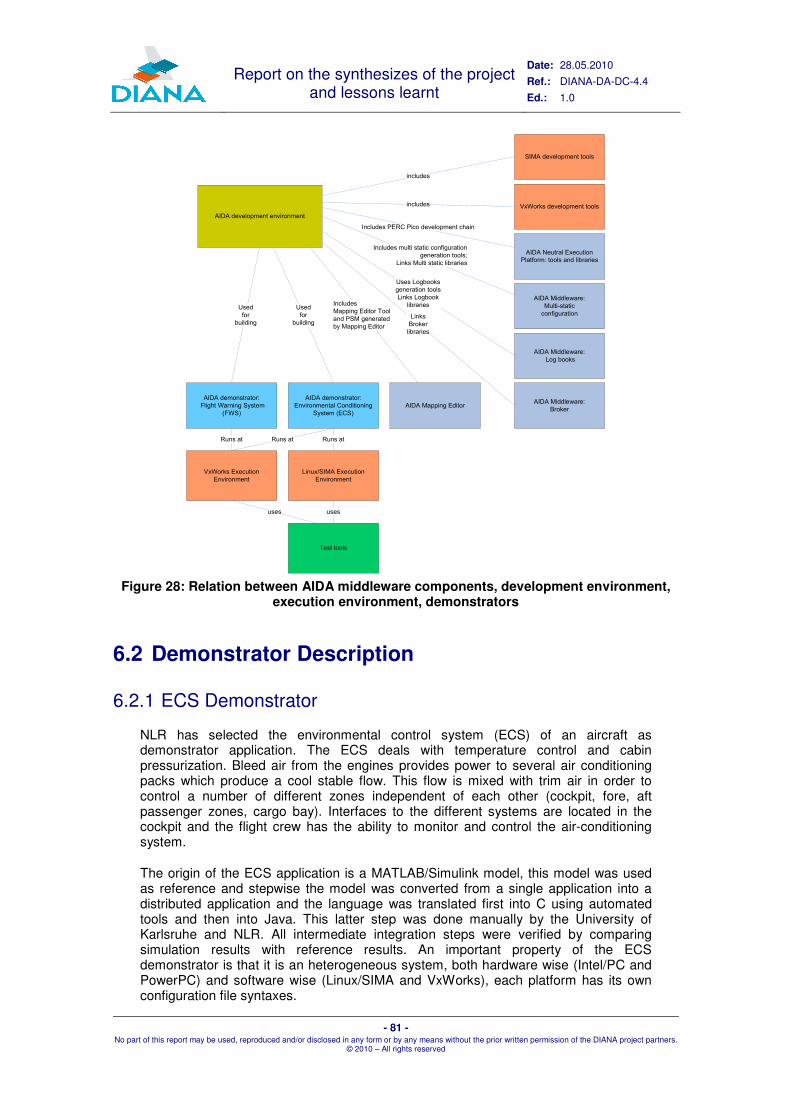
Report on the synthesizes of the project and lessons learnt
Date: 28.05.2010
Ref.: DIANA-DA-DC-4.4
Ed.: 1.0
- 81 - No part of this report may be used, reproduced and/or disclosed in any form or by any means without the prior written permission of the DIANA project partners.
© 2010 – All rights reserved
AIDA development environment
AIDA demonstrator:
Environmental Conditioning
System (ECS)
AIDA demonstrator:
Flight Warning System
(FWS)
VxWorks Execution
Environment
Linux/SIMA Execution
Environment
AIDA Middleware:
Log books
AIDA Middleware:
Broker
AIDA Middleware:
Multi-static
configuration
AIDA Neutral Execution
Platform: tools and libraries
Includes PERC Pico development chain
Includes multi static configuration
generation tools;
Links Multi static libraries
Used
for
building
Used
for
building
Uses Logbooks
generation tools
Links Logbook
libraries
Runs at Runs atRuns at
Links
Broker
libraries
AIDA Mapping Editor
Includes
Mapping Editor Tool
and PSM generated
by Mapping Editor
Test tools
SIMA development tools
VxWorks development tools
includes
includes
usesuses
Figure 28: Relation between AIDA middleware components, development environment,
execution environment, demonstrators
6.2 Demonstrator Description
6.2.1 ECS Demonstrator
NLR has selected the environmental control system (ECS) of an aircraft as demonstrator application. The ECS deals with temperature control and cabin pressurization. Bleed air from the engines provides power to several air conditioning packs which produce a cool stable flow. This flow is mixed with trim air in order to control a number of different zones independent of each other (cockpit, fore, aft passenger zones, cargo bay). Interfaces to the different systems are located in the cockpit and the flight crew has the ability to monitor and control the air-conditioning system.
The origin of the ECS application is a MATLAB/Simulink model, this model was used as reference and stepwise the model was converted from a single application into a distributed application and the language was translated first into C using automated tools and then into Java. This latter step was done manually by the University of Karlsruhe and NLR. All intermediate integration steps were verified by comparing simulation results with reference results. An important property of the ECS demonstrator is that it is an heterogeneous system, both hardware wise (Intel/PC and PowerPC) and software wise (Linux/SIMA and VxWorks), each platform has its own configuration file syntaxes.

Report on the synthesizes of the project and lessons learnt
Date: 28.05.2010
Ref.: DIANA-DA-DC-4.4
Ed.: 1.0
- 82 - No part of this report may be used, reproduced and/or disclosed in any form or by any means without the prior written permission of the DIANA project partners.
© 2010 – All rights reserved
Figure 29 depicts the NLR demonstrator setup. It consists of
� 2 Linux/SIMA PC’s providing a simulated ARINC 653 platform (Target 2 and Target 3 PC),
� a PowerPC VxWorks 653 system (Target 1 PPC) providing an actual real-time ARINC 653 platform,
� a Simulator/Testing PC providing the environment simulation and test and control facilities,
� a Display/Control PC providing the user panels on the flight deck and
� a development PC that provides AIDA development environment including build and download tools for VxWorks.
The SIMA systems don’t require a cross development environment, they are both target and development system. Note that on the Avionics 2010 exhibition the Display/Control PC was replaced by panels on the APERO flight simulator.
VxWorks
AIDA run-time
Zone
controller
Target1-PPC
Linux
Target2-PC
Linux
Simulator/Testing PC
EuroSim
ECS Simulation (for ref.)ECS Plant simulation
(Simulink models)
Eurosim&Vincent intf.
Developmnt PC
AIDA
Development
Environment
Windows XP
Display/Control PC
Cruise page
Vincent
Interface with
ECS plant
bridge
Air panel
Test
Network
Avionics Network
Deployed
Interface with
ECS plant
bridge
Windows XP
NLR
Network
Target3-PC
SIMA
Deployed
Pack
controller
AIDA run-time
SIMA
Deployed
Pack,
zone in C1, C2
AIDA run-time
Linux
Vincent
SIMA
ECS plant bridge
Figure 29: ECS Demonstrator Architecture
During WP 4.2, the WP 3 middleware components were stepwise integrated into the demonstrator. The first component integrated with the platforms and the applications was the PERC Pico based AIDA Neutral Execution Platform, next the multi-static component and finally the Logbook service. The Logbook service was only used on the ECS demonstrator because it requires a file system which is only provided by the Linux/SIMA platforms.
Integration of the different AIDA services was done during a number of workshops. First workshop in October 2009 at NLR focussed on integration of the Neutral Execution Environment, present were Embraer, GMV Skysoft, and Atego. During the next workshop at Embraer the emphasis was on multi-static and in March 2010 a third workshop was setup with GMV Skysoft and NLR to look into integration of Logbooks.
Integration of multi-static required a considerable effort. This was due to the mix of VxWorks and SIMA systems (different build structure, different configuration files), and the difference in endiannes, a minor issue, but rather persistent and at the end the signature check in VxWorks was disabled.
At the end of the workshops a sufficient level of integration was achieved to enter the test and verification phase.
Report on the synthesizes of the project and lessons learnt
Date: 28.05.2010
Ref.: DIANA-DA-DC-4.4
Ed.: 1.0
- 83 - No part of this report may be used, reproduced and/or disclosed in any form or by any means without the prior written permission of the DIANA project partners.
© 2010 – All rights reserved
6.2.2 FWS Demonstrator
In the context of work package 4, the Flight Warning System Demonstrator is an installation that allows testing the main characteristics of AIDA, such as system interoperability, reconfigurability and performance. The system is composed of (see Figure 30):
� Three modules, being two real and one simulated.
� An HMI (Human Machine Interface) that simulates the FWS interface
� Communication between modules.
The simulated module Module-2 is located on the Development, Environment & Aircraft Simulation Station, see Figure 38. The three modules host the four FWS main components:
� The FWS Core (FwsCore) manages the alerts, and elaborates the messages to be displayed on the FWS HMI. This component is instantiated twice: one instance plays the role of the primary while the other instance serves as a hot backup. In any nominal configuration of the system, two instances of the FWS core are concurrently active.
� The FWS Controller (FwsCtrl) manages redundancy between the primary and secondary FWS core. It implements a very simple algorithm in order to determine at any time which FWS core actually drives the outputs. Activation or inhibition of the FWS cores' output is performed using a dedicated communication channel (APEX port) between the controller and the core. In any nominal configuration of the system, two instances of the FWS core are concurrently active. Currently, there are two different versions of the FWS Controller: one using simple APEX ports (FwsCtrl) and another using SIA's DDS-like communication middleware (FwsCtrl-SIA). Currently, only the first version runs on the target boards.
� The System Manager and Reconfiguration Manager are used to manage multi-static reconfiguration. Please refer to SkySoft's documentations for further details.
Around this core two other computers complete the installation:
� A standard PC providing the called Development, Environment & Aircraft Simulation Station.
� A standard PC here called Test Station.

Report on the synthesizes of the project and lessons learnt
Date: 28.05.2010
Ref.: DIANA-DA-DC-4.4
Ed.: 1.0
- 84 - No part of this report may be used, reproduced and/or disclosed in any form or by any means without the prior written permission of the DIANA project partners.
© 2010 – All rights reserved
Figure 30: FWS demonstrator architecture
Figure 31: FWS Demonstrator Views
Module-0 (SBC7457 /
VxWorks 653)
Module-1 (SBC7457 /
VxWorks 653)
Development , Environment and Aircraft Simulation Station
(PC / Windows XP)
Tests Station
(PC / Linux
running
Wireshark)
1000BaseTX Ethernet Switch (Avionic Bus)
Module-2 (VxSIM –
Virtualyzed PPC module)
Bridge
Eth0 Eth1
FTP Server
HMI
host.py
Report on the synthesizes of the project and lessons learnt
Date: 28.05.2010
Ref.: DIANA-DA-DC-4.4
Ed.: 1.0
- 85 - No part of this report may be used, reproduced and/or disclosed in any form or by any means without the prior written permission of the DIANA project partners.
© 2010 – All rights reserved
6.3 Evaluation and Test Description
6.3.1 ECS Demonstrator
6.3.1.1 Verification of Java execution environment
The objective of this test was to verify nominal operation of the AIDA Neutral Execution Environment. Two aspects are considered: functional behaviour should be in line with reference results and the periodicity of transmitted message should be, within limits, constant. The original Environmental Control System (air-conditioning system) was developed in MATLAB/Simulink with the purpose to study behaviour of such a system. For DIANA the Simulink code was stepwise converted into two Java applications (Zone Controller and Pack Controller), an ARINC 653 legacy bridge application and an ECS Plant simulated by EuroSim.
During the test the AIDA NEP proved to be a stable platform and the test results were similar to results found earlier during reference runs. The monitoring of network traffic showed constant rates with little variation.
6.3.1.2 Verification of exception handling
The objective of this test was to verify the response of the AIDA NEP to exceptions. The test included response to unhandled exceptions, applications errors and exceptions invoked by the application. The Java exception handling in combination with the ARINC 653 HM worked as expected, it took some digging under the surface to find a minor implementation level issue: in some cases errors were promoted from process level to partition level due to the way the stack was manipulated by PERC Pico.
6.3.1.3 Verification of the Logbook service
The AIDA logbook system is part of the AIDA middleware. The logbook system provides location transparent, redundant logbooks to applications and improves system reconfiguration by making application hosting transparent to the logbook system. The AIDA logbook system extends the ARINC 653 logbook system, defined as extended service in part 2 of the standard. An AIDA logbook consists of a set of ARINC 653 logbooks, usually hosted on different modules and seen by client applications as one unique AIDA logbook.
The ECS application demonstrates the AIDA logbook by integrating a logbook client into the Pack Controller application. A nominal test was executed and at the end of the test the expected entries were found in the log file on the AIDA Logbook replica.
6.3.1.4 Verification of multi-static behaviour
For verification of multi-static three different configurations were defined for the ECS demonstrator: C0, all modules healthy, C1, module M2 failed (Zone Controller running on VxWorks) and C2, module M1 failed (Pack Controller running on Linux/SIMA) failed. In all failure cases after reconfiguration the failing function was moved to module M0 (Linux/SIMA). In configuration C0, M0 only executes the multi-static partitions. The healthy/no healthy state was controlled by a software constant in the system partition. In Figure 32, only the ECS related partitions are shown, in all cases the modules also contain multi-static partitions.

Report on the synthesizes of the project and lessons learnt
Date: 28.05.2010
Ref.: DIANA-DA-DC-4.4
Ed.: 1.0
- 86 - No part of this report may be used, reproduced and/or disclosed in any form or by any means without the prior written permission of the DIANA project partners.
© 2010 – All rights reserved
SIM
A
Figure 32: Multi-static nominal configuration C0
In all cases the multi-static reconfiguration went according to the defined scenario. The correct messages were exchanged and independently the healthy modules concluded the same configuration. In order to restart VxWorks in a different configuration the system partition communicated the required configuration to a Python script running on the ftp boot server, which in turn selected a different set of boot files, returned an acknowledge to the system partition and then the reconfiguration was completed by invoking a reboot. The SIMA systems obviously did not need to reboot hardware wise, instead the SIMA MOS was restarted with a different configuration file.
6.3.2 FWS Demonstrator
The Flight Warning System (FWS) was developed by Thales in the scope of WP 3. Although the implementation of this FWS demonstrator is not a complete implementation due to time and resources constraints, it did implement the most important characteristics. The aspects verified, the tests performed using the FWS demonstrator, and its main demonstrator features are according to the following table.
Related Test Test Cases Demonstrator Features
FWS Reconfiguration
68, 69 FWS integrated with 2 modules
Multi-Static Reconfiguration
5, 10, 13, 14, 62
FWS integrated with 3 modules and 3 software configurations
System manager and BSC
56, 57, 58, 59, 60 and 61
System manager and BSC integrated
Health Monitoring during startup behaviour
55 FWS integrated with 2 modules
Robustness 77 FWS integrated with 2 modules
Table 4: Tests performed using the FWS demonstrator

Report on the synthesizes of the project and lessons learnt
Date: 28.05.2010
Ref.: DIANA-DA-DC-4.4
Ed.: 1.0
- 87 - No part of this report may be used, reproduced and/or disclosed in any form or by any means without the prior written permission of the DIANA project partners.
© 2010 – All rights reserved
6.4 Results
The main cornerstones of AIDA are a model-driven development environment to reduce software development costs, a Java environment on top of ARINC 653 to enable object oriented development using currently available ARINC 653 DO-178 certified operating systems, and middleware components to shift communication between modules to a higher abstraction level and to improve dispatchability of aircrafts by selecting a configuration from a set of (pre)certified configurations at start-up.
The core functionality of components has been implemented in WP 3 by Budapest University, Atego (Aonix), GMV Skysoft and AleniaSIA. Prototype software was available for evaluation in WP 4 and three different demonstration platforms, located at Embraer, NLR and AleniaSIA, were used for evaluation and test. Each platform focused on certain functional aspects. In addition an experiment was conducted by the University of Karlsruhe with formal methods using the ECS software as use case.
Overall, it can be stated that AIDA combines very promising technologies that will help to reduce development time and effort significantly:
� The model-driven tool chain, raises the focus of design activities to platform-independent levels of abstraction; at the same time, it provides model-based strategies to define the platform mapping, including the generation of configuration artefacts and glue code fragments;
� The Java-based Neutral Execution Environment introduces a solid layer of abstraction from the underlying hardware and RTOS platform. The level of abstraction is significantly higher compared to the level provided by conventional APIs, such as the ARINC 653 APEX interfaces;
� The platform services introduce location transparent invocation of functionalities and raise the level of abstraction of interoperability, including data exchange, to a higher level; in particular the integration of the model-based technologies and the platform services promise major reductions on development time and effort.
An important conclusion is that adequate tool support is mandatory for efficient software development. In addition to the already existing ARINC 653 configuration files for SIMA and VxWorks, AIDA components require configuration files (XML type files for Logbooks and multi-static reconfiguration, C header files for the generic part of the Broker middleware) and all files should be correct, and consistent. Traceability is also an issue to consider, AIDA configuration files (e.g. Logbooks) are in many cases integrated into existing (ARINC 653) configuration files. Maintaining these files manually is a time consuming and tedious job. Full integration of all tools into one tool chain, e.g. including the PIM – PSM Mapping Editor into the SIMA and VxWorks tool chains, was not feasible within the scope of DIANA, however the use case experiment shows that an important first step is made. Note that the use of tools to generate configuration files (and the system integrator relying on those files) raises the issue of tool qualification. Another complicating factor is the large variety in hardware and operating systems, DIANA dealt with Intel/Linux/SIMA/VxSim and PowerPC/VxWorks and already it was sometimes difficult to maintain the configurations for the different platforms. Adequate tools support is also required in this area.
The use of Java provides some clear advantages (abstraction from the underlying platform, use of object oriented design and programming), however embedded and certifiable systems require control over memory use (typically hidden for the standard Java programmer) and the annotations that provide that control are not intuitive; incorrect use may lead to run-time exceptions. Improvements are required concerning documentation and the tool support.
Report on the synthesizes of the project and lessons learnt
Date: 28.05.2010
Ref.: DIANA-DA-DC-4.4
Ed.: 1.0
- 88 - No part of this report may be used, reproduced and/or disclosed in any form or by any means without the prior written permission of the DIANA project partners.
© 2010 – All rights reserved
An important design driver for the multi-static algorithm is to avoid a single master that may become a single point of failure in the AIDA configuration. Instead, modules decide independently and draw the same conclusion. The AIDA Byzantine Agreement protocol was studied intensively and the experiments in WP 4 show that it worked well. There are a number of issues that need further attention, among them the timing synchronisation during modules start-up. Due to differences in boot time, messages may be lost and modules will draw the wrong conclusion. In addition there are a number of solutions implemented which are “demonstration specific” (RSA protocol for authentication, reconfiguration mechanism for VxWorks) and these solutions need to be revisited in a next step.
The AIDA Logbook system, an extension of the ARINC 653 part 2 Logbook definition on avionics network level, is implemented on the NLR demonstrator and a number of limited experiments were conducted. The aforementioned lack of integration of tools is also applicable to the Logbook system. Although the log book configuration descriptor is a simple file, integrating configuration files generated from this descriptor into the applications' configuration files and keeping these files consistent and traceable is quite complex. Another issue is the lack of synchronisation between replicas which may results in replicas being out of sync.
The AIDA Broker is a collection of components responsible for exchange of data and events between applications residing on different partitions. The Broker middleware makes use of the ARINC 653 layer for actual data transfer. The Broker services include besides data exchange, content filtering, data fusion, unit conversion and QoS aspects (reliability, history, and resource limits). In the AIDA simulation, all configuration takes place at design time, in a complete AIDA tool chain, configurations would be auto-generated based on ICD definitions. Unfortunately, the experiments done with the AIDA Broker in the scope of the FWS and ECS demonstrators have been limited.
Several other deficiencies and limitations have been revealed during the tests and they are described in more detail in ref. [20]. Some of them are inherent to prototype software development and were already known prior to the execution of the tests, others were found during test execution. The overall conclusion of WP 4.3 was that no show stoppers were found and that the AIDA concepts are viable, taking into account that the WP 4 evaluation only covers a limited number of aspects of the AIDA components and that further research and development is required.

Report on the synthesizes of the project and lessons learnt
Date: 28.05.2010
Ref.: DIANA-DA-DC-4.4
Ed.: 1.0
- 89 - No part of this report may be used, reproduced and/or disclosed in any form or by any means without the prior written permission of the DIANA project partners.
© 2010 – All rights reserved
77 WWPP55:: DDIISSSSEEMMIINNAATTIIOONN
7.1 Objectives and Means
The dissemination strategy aimed at two main goals: 1) AIDA should be accepted by the avionics industry and 2) DIANA standardisation and certification efforts should be reflected in the real world. To reach the first goal, two main strategies were followed:
� User Forums: Main goal of the User Forums is to make project results public and to gather feedback from the industry. The DIANA project should be recognised as an important activity within the avionics community. For this, community members should feel that they are involved in the process, knowing DIANA already in an early stage of development and having the opportunity to contribute.
Two User Forums have been planned: one, at the Farnborough Airshow 2008, the other, initially foreseen for Paris Airshow, 2009, but adjourned to the Avionics Event, March 2010 in Amsterdam. The first User Forum at Farnborough was centred around talks about aspects of the AIDA platform, like neutrality, interoperability, development and certification means (see section 7.3.1 below). The second event at Avionics 2010 was not a User Forum in the strict sense. It aimed at presenting AIDA by means of a demonstrator (see section 7.3.2 below).
� Participation in conferences and scientific articles: The technology developed during the DIANA project has been made known by presenting papers at conferences dedicated to the technology areas (modelling, Java etc.) and the industry (aerospace). Since it was deemed important not only to make the technologies and products known to the industry, but to develop confidence in their maturity and future certifiability, scientific dissemination had an important role in the project. Section 7.2 will present a selection of papers that have been presented by DIANA consortium members.
The second goal was pursued by partners with presence in standardisation bodies and industrial forums. Proposals aiming at establishing DIANA related technology as avionics standards made to standardisation bodies; the advantages and the feasibility of these technologies were demonstrated to industry representatives in industrial forums by presenting research papers. The DIANA White Paper supported these activities.
7.2 Scientific Papers
7.2.1 Aspects of “Architecture for Independent Distributed Avionics”, DASC 2008
The “Architecture for Independent Distributed Avionics” (AIDA) middleware, under definition by the DIANA consortium, aims to improve current ARINC 653 middleware by providing new services to increase interoperability between applications, to support Safety Critical Java applications, to reduce the impact of software changes. Also it
Report on the synthesizes of the project and lessons learnt
Date: 28.05.2010
Ref.: DIANA-DA-DC-4.4
Ed.: 1.0
- 90 - No part of this report may be used, reproduced and/or disclosed in any form or by any means without the prior written permission of the DIANA project partners.
© 2010 – All rights reserved
provides a better support at system level: enhancing the integration between services on different processing modules and with non AIDA systems.
Finally, an important feature proposed by AIDA, related to system reconfigurability, improving aircraft dispatchability with less processing modules, is also covered in this paper.
7.2.2 Tool Support for Engineering Certifiable Software, SafeCert 2008
Formal methods can effectively support the model driven development and analysis of IT applications in many domains. Typically, the domain-specific engineering models are transformed to formal analysis models (to compute measures that help the designer in verifying the design decisions) and verified models are mapped to test and implementation related software artefacts. An overview of four European projects demonstrates the use of support tools and tool integration facilities in development processes of systems having in sight the demand of certification according to domain-specific standards.
7.2.3 CSP(M): Constraints Satisfaction Problem over Models, MODELS 2009
Constraint satisfaction programming (CSP) has been successfully used in model-driven development (MDD) for solving a wide range of (combinatorial) problems. In CSP, declarative constraints capture restrictions over variables with finite domains where both the number of variables and their domains are required to be a priori finite. However, the existing formulation of constraint satisfaction problems can be too restrictive to support dynamically evolving domains and constraints necessitated in many MDD applications as the graph nature of the underlying models needs to be encoded with variables of finite domain. In the paper, we reformulate the constraint satisfaction problem directly on the model-level by using graph patterns as constraints and graph transformation rules as labelling operations. This allows expressing problems composed of dynamic model manipulation and complex graph structural constraints in an intuitive way. Furthermore, we present a prototype constraint solver for the domain of graph models built upon the VIATRA2 model transformation framework, and provide an initial evaluation of its performance.
This paper was invited to a special MODELS 2009 issue of the Springer Software and System Modeling journal (submitted).
7.2.4 Workflow-Driven Tool Integration Using Model Transformations, Manfred Nagl Festschrift, 2010 (Springer book chapter)
The design of safety-critical systems and business-critical services necessitates to coordinate between a large variety of tools used in different phases of the development process. As certification frequently prescribes to achieve justified compliance with regulations of authorities, integrated tool chain should strictly adhere to the development process itself. In order to manage complexity, we follow a model-driven approach where the development process is captured using a precise domain-specific modelling language. Each individual step within this process is represented transparently as a service. Moreover, to carry out individual tasks, systems engineers are guided by semi-automated transformation steps and well-formedness constraint

Report on the synthesizes of the project and lessons learnt
Date: 28.05.2010
Ref.: DIANA-DA-DC-4.4
Ed.: 1.0
- 91 - No part of this report may be used, reproduced and/or disclosed in any form or by any means without the prior written permission of the DIANA project partners.
© 2010 – All rights reserved
checking. Both of them are formalized by graph patterns and graph transformation rules as provided by the VIATRA2 framework. In our prototype implementation, we use the popular JBPM workflow engine as orchestration means between different design and verification tools. We also give some insights how this tool integration approach was applied in the DIANA EU-FP6 project.
7.2.5 Towards Certifiable Model Transformations: A Survey, Submitted to ACM Survey, 2010
Since model driven development (MDD) has become more and more popular in the field of critical systems development (including avionics applications as well), the quality of model transformations, which are the main driver of MDD, have become a major issue. In the paper, first, we overview possible correctness criteria for model transformations. Then a general architecture for various model transformation artefacts is discussed, which can be aligned with documents and artefacts required in a certification process. We provide a survey on verification and validation approaches for model transformations with respect to these categories. Finally, we identify gaps for future research in the field.
7.2.6 Model-Driven Development of ARINC 653 Configuration Tables, DASC 2010
In the paper, we present a framework for systematically designing standard ARINC 653 configuration tables with additional support for configuring (i) the Wind River VxWorks RTOS and (ii) the GMV SIMA ARINC 653 simulation platform. Additionally, parallel to the development process our approach generates end-to-end traceability information to support certification and better error confinement for V&V activities.
This approach was developed in the context of the DIANA project financed by the European Commission through the Sixth Framework Programme.
7.2.7 Use of PERC Pico in the AIDA Avionics Platform, JTRES 2009 and ERTS 2010
In this paper, we present the DIANA experiment on the use of Java in avionics safety critical applications. First, we discuss some concerns about the porting of the Java platform on the ARINC 653 operating system. Then the paper focuses on some important features of the Safety Critical Java Technology adopted in the project. Particular attention is turned on the Java memory model which is stack-based as opposed to the ongoing JSR-302 memory regions model. Benefits and issues of this approach are discussed through a real use case implementation representing part of a Flight Warning System.
7.2.8 Enhanced Dispatchability of Aircrafts, using Multi-Static Configurations, ERTS 2010
This paper describes the reconfiguration strategy and mechanisms adopted in the Integrated Modular Avionics (IMA) based platform designed and evaluated in the scope of the European research and development project DIANA. The mechanisms aim at improving dispatchability of aircrafts while keeping a reasonable and limited impact on certification costs.

Report on the synthesizes of the project and lessons learnt
Date: 28.05.2010
Ref.: DIANA-DA-DC-4.4
Ed.: 1.0
- 92 - No part of this report may be used, reproduced and/or disclosed in any form or by any means without the prior written permission of the DIANA project partners.
© 2010 – All rights reserved
The paper first introduces the concept of multi-static reconfiguration i.e., a set of pre-qualified configurations from which the active one will be autonomously selected according to the system health state at system start-up. A configuration selection mechanism, exploiting a Byzantine Agreement algorithm, is discussed. Particular attention is paid to the proof of correctness of the adopted algorithm. Practical considerations concerning its implementation, like, for instance, the authentication protocol to be used are also considered. Finally, the implementation of the mechanism on top of an ARINC 653 Application Executive is briefly described.
7.3 Events
7.3.1 Farnborough 2008
The DIANA project was present at Farnborough Airshow 2008. Two sessions were held, one in the Morning, the other in the Afternoon. During these sessions the technology proposed by DIANA were discussed. The session in the Morning presented the whole approach, the session in the Afternoon focused on the interoperability architecture.
In the Morning session, around thirty guests from General Dynamic, General Electric, Augusta Westland, Alenia, THALES, Dassault, Embraer and others, were present. Contacts have been exchanged and further information, such as the white paper, public reports etc. have been distributed. The Afternoon session was smaller. Mainly Embraer people were present.
7.3.2 Avionics 2010
AIDA was presented during the Avionics Event Exhibition in Amsterdam, March 2010. AIDA was presented by means of a demonstrator integrating AIDA components, the ECS application with the EuroSim simulator and the APERO flight simulator (see Figure 33).

Report on the synthesizes of the project and lessons learnt
Date: 28.05.2010
Ref.: DIANA-DA-DC-4.4
Ed.: 1.0
- 93 - No part of this report may be used, reproduced and/or disclosed in any form or by any means without the prior written permission of the DIANA project partners.
© 2010 – All rights reserved
ECS target systems
results displayed by
EuroSim
APERO flight
simulator
Integrated ECS
control panels
Figure 33: AIDA Demonstrator at Avionics 2010
The demonstrator used real on-board hardware, visible on the table on the left-hand side of the picture, below the upper display. On the upper display three things were shown: The output of the SIMA ARINC 653 simulator, visualising the demonstrator partitions, A component diagram explaining the ECS application and the output of the EuroSim simulator showing the effect of changing the control variables to the environment. On the lower display, a flash demonstration of DIANA was presented.
The human-machine interface to control the ECS had been integrated with the APERO flight simulator on the right-hand side of the picture. The flight simulator was set-up as an Airbus A320. The ECS controls had been integrated into the cockpit in a realistic way.
The demonstrator was an eye-catcher during the exhibition and attracted many visitors. DIANA concepts had been discussed during more than thirty individual talks. Additional information was distributed to interested people after the trade show.
7.4 Relation to other Projects
7.4.1 DECOS
The DECOS [34] project (Dependable Embedded Components and Systems) aimed the definition of a general methodology for the development of safety-critical embedded systems based on the time-triggered architecture. It defined and implemented a complete Model-Based development framework that used high level visual languages for the definition of platform independent model of the system and using complex model transformations generated both the source code and the configuration descriptors of the system. The whole process was applied to various domains like, control system, automotive and avionics.
Based on the experience gained in the DECOS project for the definition and development of complex Model-Driven Development processes. In the DIANA project

Report on the synthesizes of the project and lessons learnt
Date: 28.05.2010
Ref.: DIANA-DA-DC-4.4
Ed.: 1.0
- 94 - No part of this report may be used, reproduced and/or disclosed in any form or by any means without the prior written permission of the DIANA project partners.
© 2010 – All rights reserved
we aimed to enhance (i) the definition of the development process with executable workflow based integration models with support for the definition of roles, data elements and validation contracts, (ii) V&V activities by tight integration to the development process for early model based error-detection and (iii) traceability between model-to-model and model-to-code.
7.4.2 MOGENTES
MOGENTES [33] (Model-based Generation of Tests for Dependable Embedded Systems) aims at enhancing testing and verification of dependable embedded systems by means of automated generation of test cases relying on (i) high-level models as the definition of the system serving as the input for various model based test case generation approaches.
Within DIANA we integrated techniques proposed in the MOGENTES project to the AIDA Development Means. The aim was to demonstrate the feasibility of model based testing as an integrated V&V activity parallel to the development process.
7.4.3 SCARLETT
The FP7 project SCARLETT (see www.scarlettproject.eu) aims at the definition of the next generation of IMA. The first generation has been introduced through the European funded research projects PAMELA, NEVADA and VICTORIA. It has led the aerospace industry to take a revolutionary step away from the previous federated architectures. SCARLETT research aims at a conceptual breakthrough in IMA to define a scalable, reconfigurable fault-tolerant driven and secure new avionics platform, namely DME: Distributed Modular Electronics. The SCARLETT objectives are similar to those of DIANA, where DIANA focuses more on software, SCARLETT more on the integration of electronic equipments.
DIANA offered the Interface Control Document to SCARLETT that is currently used in the scope of SCARLETT WP2.1 and 2.4. Also, reconfiguration has been discussed with SCARLETT sub-project leaders.
7.4.4 JEOPARD
The main strategic objective of the JEOPARD project (www.jeopard.org) is to provide the tools for platform independent development of predictable systems that make use multi-core platforms. These tools will enhance the software productivity and reusability by extending technology that is established on desktop system by the specific needs of multi-core embedded systems. The project will actively contribute to standards required for the development of portable software in this domain.
Investigating potential multi-core architectures for avionics is one of the objectives defined in the DIANA proposal. However, only little effort could be spent on this aspect during the project. Therefore, SKY exploits the JEOPARD project to continue the research on multi-core and avionics architectures. SKY developed an IMA-based use case for the JEOPARD platform. This use case was ported to Real-Time and Safety Critical Java and optimised for multi-core platforms.

Report on the synthesizes of the project and lessons learnt
Date: 28.05.2010
Ref.: DIANA-DA-DC-4.4
Ed.: 1.0
- 95 - No part of this report may be used, reproduced and/or disclosed in any form or by any means without the prior written permission of the DIANA project partners.
© 2010 – All rights reserved
7.4.5 GENESYS
The aim of the GENESYS (GENeric Embedded SYStem Platform) project is to develop a cross-domain reference architecture for embedded systems meeting the requirements proposed in the ARTEMIS SRA. These ARTEMIS requirements mainly focus on composability, networking and security, robustness, diagnosis and maintenance, integrated resource management and evolvability . Its reference architecture is domain-independent and will serve as a template that can be instantiated to concrete platforms for individual application domains (i.e., automotive, avionic, industrial control, etc.)
7.4.6 INDEXYS
The objective of INDEXYS (INDustrial EXploitation of the genesYS cross-domain architecture) is to tangibly realize industrial implementations of cross-domain architectural concepts developed in the GENESYS project in three domains: automotive, aerospace and railway. Additionally, INDEXYS expands the GENESYS approach by implementing and integrating architectural services into prevailing (real-world!) platform solutions. A key goal of INDEXYS is legacy integration, for plat-form providers – by integrating new architectural services into legacy platforms – and for platform users – by supporting legacy applications.
Both GENESYS and INDEXYS are ARTEMIS FP7 projects. Both heavily rely on MDD approaches as GENESYS defines the PIM meta-model while INDEXYS develops a possible PSM with a complete platform and services implementation and tool support.

Report on the synthesizes of the project and lessons learnt
Date: 28.05.2010
Ref.: DIANA-DA-DC-4.4
Ed.: 1.0
- 96 - No part of this report may be used, reproduced and/or disclosed in any form or by any means without the prior written permission of the DIANA project partners.
© 2010 – All rights reserved
88 GGUUIIDDEELLIINNEESS FFOORR FFUUTTUURREE PPRROOJJEECCTTSS
8.1 Technical Concerns
The project encountered a lot of technical problems on the level of specification and implementation. Those problems were caused by different factors, including the complexity of the addressed topics and the lack of a tool chain for the implementation of the AIDA simulation and the use cases. Further activities in this area shall focus on the integration of tools as a major factor of success for the next generation IMA platforms, including promising development approaches like model-driven engineering. For more details, please refer to sections 3 AIDA Overview and 9 Conclusion.
Note that this aspect has been taken into account in the SCARLETT project where a huge work package, compared to the DIANA dimensions, defines a Distributed IMA development environment.
8.2 Management Concerns
8.2.1 Adopt a more iterative / incremental approach
DIANA is a far reaching research project. In such a context, the clear definition of requirements is difficult. Some of the requirements were, hence, unclear or at least fuzzy: this fact simply reflects diversity of involved people, complexity of the tackled problem, and richness of proposed ideas.
However, associated with the followed waterfall approach, this may explain part of the difficulties that were met in elicitation of AIDA specifications. By trying to solve many issues at once, the project didn't manage to completely integrate the different parts and productions (e.g., model based tools, certain AIDA features, etc.) of the projects.
Adopting a more iterative and incremental approach combined with early prototyping for future similar technological activities would certainly be more pragmatic, and avoid some of the met issues. This would shorten the different work packages, and facilitate its management, by providing a finer grain of control.
8.2.2 Adopt specific licences for reusable work
During the project, a question arose: would it be possible to reuse certain DIANA outputs in another European project – namely ICD meta model for SCARLETT? Doing so was obviously in the DIANA objectives. The dissemination level of the ICD document, written in the context of work package 3.3, was even changed from confidential (i.e. restricted to DIANA consortium members) to public, in order to make it useful beyond DIANA. Practically, this request raised several related questions. Could DIANA partners be informed of changes made by the other project, notably when they don’t directly participate to this other project? Could they participate to the evolution of this work? Could they have access, in the end, to the derivative work? Wasn't there

Report on the synthesizes of the project and lessons learnt
Date: 28.05.2010
Ref.: DIANA-DA-DC-4.4
Ed.: 1.0
- 97 - No part of this report may be used, reproduced and/or disclosed in any form or by any means without the prior written permission of the DIANA project partners.
© 2010 – All rights reserved
any risk that the provided data would be turned into proprietary ones, so that the original authors couldn't even use their own work?
Handling of such situation should be defined clearly in future contracts. For such cases, it would seem worth adopting a specific licence (similar to Creative Common), guaranteeing rights of contributors. EC could even propose or suggest a list of possible licences for similar works.
8.2.3 Technology Availability
The proposal foresees the use of technology available in the project consortium or the use of free and open source software. This approach seems appropriate for a research undertaking. However, some of the needs could not be met by available COTS or FOSS tools. Consequently, the project contacted tool vendors and suppliers, such as Wind River, OIS and CES to get their support for the DIANA project. Even if this approach was partly successful due to the willingness of those companies to cooperate, it meant that the success of the project depended on external factors out of the control of the DIANA management.
Future activities shall ensure that the technology that is necessary to fulfil the project goals are either available or its costs are reflected in the budget.

Report on the synthesizes of the project and lessons learnt
Date: 28.05.2010
Ref.: DIANA-DA-DC-4.4
Ed.: 1.0
- 98 - No part of this report may be used, reproduced and/or disclosed in any form or by any means without the prior written permission of the DIANA project partners.
© 2010 – All rights reserved
99 CCOONNCCLLUUSSIIOONN
The main goal of DIANA was the definition of the next generation IMA platform AIDA, answering the need for more efficient onboard software development. In the view of ever growing avionics software size, development, maintenance and, in particular, certification efforts must be reduced.
The project has investigated a bunch of technologies, such as Safety Critical and Real-Time Java, Data Distribution Services, CORBA, platform services as well as model-driven engineering and formal methods. The project revealed potential for enhancements in onboard software development, using this kind of technologies. In particular Java, data-centric interoperability and model-driven engineering were considered valuable approaches to raise the level of abstraction from the underlying hardware architecture and the operating system and, hence, to implement more efficient development processes and ease the software code and certification credit reuse.
A challenge to the project was the integration of these new technologies into one IMA platform. However, the project consortium faced this challenge and developed a full specification of the platform, describing a Java-based execution environment, data-centric interoperability, based on Data Distribution Services, platform services, such as file system, health monitor, logbooks and reconfiguration services.
Moreover, the DIANA consortium built a prototype for the future AIDA platform, partly by simulating some of the functionalities. The prototype focused on a subset of AIDA that was considered innovative, promising, challenging and, thus, worth to be demonstrated. Namely, the following components have been integrated into the prototype:
� The Java execution environment, based on PERC Pico;
� The AIDA Broker, implementing data-centric interoperability and Inter-Application Services;
� The AIDA Logbook System as an example for platform services;
� The AIDA Reconfiguration Engine, based on Multi-Static Configurations and Byzantine Agreement;
� A modelling tool chain, with a mapping editor, guiding the mapping of platform independent models to the underlying platform.
Of course, not all problems, foreseen during requirements definition and specification phase or revealed during implementation, could be solved in the scope of the project. In particular, the interoperability platform is still based on simulation means (e.g. BIT results in the reconfiguration engine are not “real”, AIDA Broker is configured by manually changing header files, tool integration is incomplete etc.). For more details, see the evaluation report DC4.3.
On the other hand, strong and, in some parts, exceptional results have been achieved. This is certainly true for the quality level of the Java execution environment. The environment is stable on several platforms and, as has been shown in WP4, provides platform independence to Java applications. For the interoperability platform, even if less stable than the execution environment, has proven to be built on reliable concepts. With the use of formal methods, the correctness of the specified algorithms

Report on the synthesizes of the project and lessons learnt
Date: 28.05.2010
Ref.: DIANA-DA-DC-4.4
Ed.: 1.0
- 99 - No part of this report may be used, reproduced and/or disclosed in any form or by any means without the prior written permission of the DIANA project partners.
© 2010 – All rights reserved
could be proved; in the scope of WP4.2, the middleware components were completely integrated with the demonstrator applications, validating, not only the correct implementation of the AIDA simulation, but, more important, the appropriateness of the AIDA specification.
At the same time, certification issues have been studied carefully. WP2.4 and 3.4 analysed the Java language and the PERC Pico implementation of Safety Critical Java in particular. Special focus was put on memory management which is believed to be the main barrier for the acceptance of Java in the avionics domain. Also, an important step towards the analysis of the code created by the PERC Pico tool chain has been made.
The interoperability middleware has been analysed, with focus on the specification, but also considering design decisions, taken during simulation development, and issues left open for future research. One of the results of the analysis of the interoperability architecture is that such a platform, once proven certifiable, may ease the certification process for hosted applications. There are, of course, still problems to solve, but components such as data-centric interoperability, reconfiguration, based on proven algorithms and standardised platform services will improve the overall reliability of the platform and ease the reuse of certification credits.
An important lesson learnt, mainly during WP3 and 4, is the importance of a fully integrated tool chain. A tool chain does not just ease some steps in application development and system integration; it is essential. The project team spent a lot of time on small integration issues related to differences of the operating systems, the hardware platforms, the build chains and so on. It was not expected in the early phase of the project that DIANA would be able to develop such a fully integrated tool chain. However, not having it available during demonstrator development proved to be a major challenge. This is in particular true because the AIDA system brings very different technologies together and defines an ambitious model-driven engineering approach as the backbone for the tool chain.
The promising solutions investigated in DIANA are a concrete step on meeting airframers and airliners (maintenance operations aspects) objectives and requirements for reduction of the different overheads, such as weight / volume / cost / wiring / power consumption or, as a result of the reconfiguration service, a minimum set of spare equipments) of the avionics systems, in combination with availability, reliability and dispatchability improvements achieved.
Regarding dissemination and potential future exploitation of DIANA results, the consortium initiated contacts and a network for possible future activities. Important partners for technical topics were Objective Interface Systems and Wind River; representatives of both companies have been involved in the development and integration process. Both companies are interested in future research in the area. Also valuable was the support by Creative Electronics Systems that ported a board support package to the VxWorks 653 version 2.2, used during AIDA integration.
DIANA initiated contacts with other European research projects in aeronautics and real-time and embedded system development, most important of which is SCARLETT. Technical topics like reconfiguration have been discussed with SCARLETT members and DIANA delivered public reports, e.g. the Interface Control Document to the SCARLETT project. Besides having different focus – DIANA mainly on software, SCARLETT on overall system integration – the projects have similar approaches for common problems, such as platform reconfiguration or platform services. It is expected that DIANA and SCARLETT achievements will influence future standards in avionic system development as, for example, the ARINC 653 specification.

Report on the synthesizes of the project and lessons learnt
Date: 28.05.2010
Ref.: DIANA-DA-DC-4.4
Ed.: 1.0
- 100 - No part of this report may be used, reproduced and/or disclosed in any form or by any means without the prior written permission of the DIANA project partners.
© 2010 – All rights reserved
1100 GGLLOOSSSSAARRYY
Aircraft function – A capability of the aircraft that is provided by the hardware and software of the systems on the aircraft. Functions include flight control, autopilot, braking, fuel management, flight instruments, etc. (based on DO-297 definition)
Aperiodic task – a task that is released in response to the occurrence of an event. If a minimum inter-arrival time for events is defined the responding task is called sporadic (see Task).
Application – Software that performs a specific function on the aircraft. An application may be composed of one or more partitions, which by their turn are composed of processes. (based on ARINC-653 definition)
Asynchronous communication – A synchronization protocol between producer and consumers tasks.
Configuration – Set of parameters characterizing a given mission.
Component – A hardware part, software part, database, or combination thereof with contractually defined interfaces and explicit context dependencies. A component can be independently deployed, replaced and combined with other components without modification.
Control coupling – The manner or degree by which one software component influences the execution of another software component.
CORBA – is the acronym for Common Object Request Broker Architecture, Object Management Group’s open, vendor-independent architecture and infrastructure that computer applications may use to work together over networks. It enables software components written in different computer languages and running on different computers to interoperate.
Core Software – The operating system and support software that manage platform resources to provide an environment in which an application can execute. Core software is a necessary element of a platform and is typically comprised of one or more modules.
Data coupling – The dependence of a software component on data not exclusively under the control of that software component.
Database – A set of data, part or the whole of another set of data, consisting of at least one data storage that is sufficient for a given purpose or for a given data processing system.
DDS – is the acronym for Data Distribution Service for Real-time Systems. It is an Object Management Group specification of a publish/subscribe middleware for distributed real-time systems created in response to the need to augment CORBA with a data-centric publish-subscribe specification.
Report on the synthesizes of the project and lessons learnt
Date: 28.05.2010
Ref.: DIANA-DA-DC-4.4
Ed.: 1.0
- 101 - No part of this report may be used, reproduced and/or disclosed in any form or by any means without the prior written permission of the DIANA project partners.
© 2010 – All rights reserved
Determinism – The degree that a system's state at time t+dt is determined by its state at time t.
FEDERATED SYSTEMS – Aircraft equipment architecture consisting of primarily line replaceable units that perform a specific function, connected by dedicated interfaces or aircraft system data buses.
Function – A named capability that performs a specific activity.
GATEWAY – is an A653 System Partition managing communication at network domain level. Here it shall be viewed as an entity customized for use within AIDA framework
ICD – The Interface Control Documentation serves as a structured way to define the communication interfaces between elements of loosely coupled distributed system.
Integrated Modular Avionics (IMA) – A shared set of flexible, reusable, and interoperable hardware and software resources that, when integrated, form a platform that provides services, designed and verified to a defined set of safety and performance requirements, to host application performing aircraft functions.
INTEROPERABLE – the capability of several integrated modules to operate together to accomplish a specific goal or function. This requires defined interface boundaries between the modules and allows the use of other interoperable components. To describe this concept in physical terms, an IMA platform may include interoperable modules and components such as physical devices (processor, memory, electrical power, Input/Output (I/O) devices), and logical elements, such as an operating system, and communication software.
MODEL DRIVEN ARCHITECTURE AND ENGINEERING – is a system engineering paradigm which facilitates the construction of precise models and automated generation of application code based upon these models. Its most well-known derivative is Model Driven Architecture (MDA) promoted by the Object Management Group (OMG), which proposes most essential standard technologies to support model driven engineering.
Model driven system development - MDSD is a system engineering paradigm which facilitates the construction of precise models and automated generation of application code based upon these models. Its most well-known derivative is Model Driven Architecture (MDA) promoted by the Object Management Group (OMG), which proposes most essential standard technologies to support model driven engineering.
Module – A hardware unit containing at least a processor, a memory bank and a networking device to connect the module to other modules.
Mutual exclusion – A synchronization protocol to enforce serialized access to a shared resource.
Object – Any collection of memory used by a program, either data or threads.
Object Oriented Programming – is a programming paradigm that uses "objects" (an object being a software bundle of related state and behavior) to design applications and computer programs. It utilizes several techniques from previously established paradigms, including inheritance, modularity, polymorphism, and encapsulation.

Report on the synthesizes of the project and lessons learnt
Date: 28.05.2010
Ref.: DIANA-DA-DC-4.4
Ed.: 1.0
- 102 - No part of this report may be used, reproduced and/or disclosed in any form or by any means without the prior written permission of the DIANA project partners.
© 2010 – All rights reserved
Operating System (OS) – (1) The same as executive software. (2) The software kernel that services only the underlying hardware platform. (3) Software that directs the operations of a computer, resource allocation and data management, controlling and scheduling the execution of computer hosted applications, and managing memory, storage, input / output, and communication resources.
Partition – An allocation of resources, including instruction code and data, whose properties are guaranteed and protected by the platform from adverse interaction and influences from outside the partition.
The operating system has absolute control over a partition’s use of processing time, memory, and other resources such that each partition is isolated from all others sharing the core module. Processes are allocated in partition to ensure that only intended coupling occurs, provide fault containment, and ease verification, validation and certification.
Partitioning – an architectural technique to provide the necessary separation and independence of functions or applications to ensure that only intended coupling occurs.
PDM – the Platform Description Model defines the HW elements and resources for a concrete implementation platform (e.g., TTTech time triggered architecture, ARINC-653 RTOS, etc.).
Periodic Task – a task that is released periodically.
PIADL – The Platform Independent Architectural Description Language is a platform independent model for describing architecture of message and event based embedded systems.
Platform – A module or group of modules, including core software that manages resources in a manner sufficient to support at least one application. IMA hardware resources and core software are designed and managed in a way to provide computational communication, and interface capabilities for hosting at least one application. Platforms, by themselves, do not provide any aircraft functionality. The platform establishes a computing environment, support services, and platform-related capabilities, such as health monitoring and fault management. The IMA platform may be accepted independently of the hosted applications.
Pluggable Service – is a concept of standardization of service interface to services to be added (plug) or removed in the AIDA platform without adverse effect.
Portability – the ease with which a software can be transferred from one computer, hardware, software or platform environment to another with no or minimal change to the software to operate correctly in the subsequent environment.
Predictability – The degree that a correct forecast of a system's state can be made either qualitatively or quantitatively
Priority – A value associated with an action that is used by an allocation policy to resolve contention for shared resources.
Process – A task defined at the level of an ARINC 653 compliant OS.
Processor – A device used for processing digital data.

Report on the synthesizes of the project and lessons learnt
Date: 28.05.2010
Ref.: DIANA-DA-DC-4.4
Ed.: 1.0
- 103 - No part of this report may be used, reproduced and/or disclosed in any form or by any means without the prior written permission of the DIANA project partners.
© 2010 – All rights reserved
Program – The set of tasks running in the same partition together with the resources allocated by them in this same partition.
Pseudo Partition – it is "a device, subsystem, or software which is not an ARINC653 hosted application".
Resource – Any object (processor, memory, software, data, etc) or component used by a processor, IMA platform, core software, or application. A resource may be shared by multiple applications or dedicated to a specific application. A resource may be physical (a hardware device) or logical (a piece of information).
Response – The computational work that must be performed as a consequence of the occurrence of an event.
RT-CORBA – is an extension to CORBA providing a middleware technology for distributed real-time systems needing support for end-to-end predictability for operations.
Service – A mechanism to enable access to one or more capabilities, where the access is provided using a prescribed interface and is exercised consistent with constraints and policies as specified by the service description.
Sporadic Task – a task that is released in response to the occurrence of an event with a minimum inter-arrival time. Sporadic Tasks become ready to execute at variable but bounded intervals.
Synchronization – Interaction between tasks through a given protocol, which causes one task to wait for another to reach a certain point in its processing before continuing asynchronous processing.
System Partition – an architectural artefact supporting the Inter-Module Communication addressing the aspects related to communication among independent distributed, i.e.: collocated on separated cabinets partitions (avionics).
System – A collection of hardware and software components organized to accomplish a specific function or set of functions.
System State – The set of variables and their current values at a given point in time during system execution.
Task – A unit of execution that executes concurrently with other Tasks of the same Partition. Task within a Partition share address space with each other and interact directly by means of accessing global variables and using synchronization protocols. The synchronization protocol as well as additional inter task communication means are implementation dependent.
A Task may be periodic or aperiodic.
Periodic Task – A task that is released periodically.
Aperiodic Task – A task that is released in response to the occurrence of an event. If a minimum inter-arrival time for events is defined the responding task is called sporadic.
Sporadic Task – A task that is released in response to the occurrence of an event with a minimum inter-arrival time. Sporadic Tasks become ready to execute at variable but bounded intervals.

Report on the synthesizes of the project and lessons learnt
Date: 28.05.2010
Ref.: DIANA-DA-DC-4.4
Ed.: 1.0
- 104 - No part of this report may be used, reproduced and/or disclosed in any form or by any means without the prior written permission of the DIANA project partners.
© 2010 – All rights reserved
Thread – An OS independent task defined at the language level.
Validation – checks that the product design satisfies or fits the intended usage (high-level checking) — i.e., you built the right product.
Verification – ensures that the final product satisfies or matches the original design (low-level checking) — i.e., you built the product right.