Embed Size (px)
Citation preview

DC bridge circuits
This worksheet and all related files are licensed under the Creative Commons Attribution License,version 1.0. To view a copy of this license, visit http://creativecommons.org/licenses/by/1.0/, or send aletter to Creative Commons, 559 Nathan Abbott Way, Stanford, California 94305, USA. The terms andconditions of this license allow for free copying, distribution, and/or modification of all licensed works bythe general public.
Resources and methods for learning about these subjects (list a few here, in preparation for yourresearch):
1

Questions
Question 1
Calculate the output voltages of these two voltage divider circuits (VA and VB):
100 VDC
25 kΩ
47 kΩ
A B
VA VB
100 VDC
33 kΩ
10 kΩ
Now, calculate the voltage between points A (red lead) and B (black lead) (VAB).file 01725
Question 2
Calculate the output voltages of these two voltage divider circuits (from point A to ground, and frompoint B to ground:
100 VDC
25 kΩ
47 kΩ
100 kΩ(set to 75 % position)
AB
VA VB
Now, calculate the voltage between points A (red lead) and B (black lead).file 00542
2
Question 3
How much voltage needs to be dropped across resistor R1 in order to make voltage VAB equal to zero?
A BVAB36 VDC
10 kΩ
30 kΩ
R1
60 kΩ
How much resistance must R1 possess in order to drop that amount of voltage?file 00543
Question 4
A thermistor is a special resistor that dramatically changes resistance with changes in temperature.Consider the circuit shown below, with two identical thermistors:
+to +to
10 kΩ 10 kΩ
V
The ”+to” label in each one shows that they both have positive α coefficients.How much voltage would you expect the voltmeter to register when the two thermistors are at the exact
same temperature? Which thermistor would have to become hotter in order to cause the voltmeter to reada significant negative voltage?
file 01751
3

Question 5
In general terms, describe what must be done to balance this bridge circuit. What, exactly, does theterm ”balance” mean in this context?
+V
-
R1
R2
R3
R4
Also, write an equation containing only the four resistor values (R1, R2, R3, and R4) showing theirrelationship to one another in a balanced condition.
file 00544
Question 6
Identify the most important qualification for the ”null” meter used to balance a bridge circuit. In otherwords, describe what type of meter we would be looking for if we were to select one for use as a ”null” meter.Describe why this particular quality is important.
file 00545
Question 7
What will happen to the voltage between points A and B if the power supply voltage increases?
A B
50 kΩ
50 kΩ
10 kΩ
10 kΩ
file 00546
4
Question 8
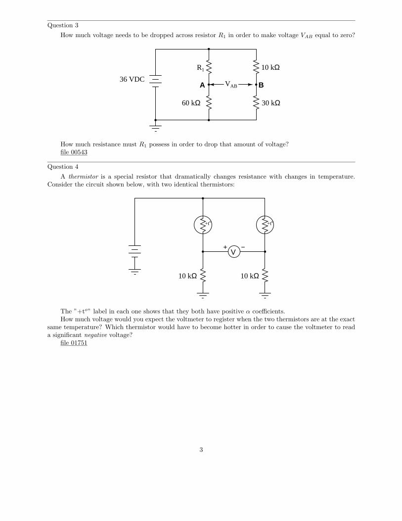
Explain how this bridge circuit is capable of being ”balanced” for any values of R1 and R2:
R1
R2
G Rpot
file 03474
Question 9
Complete the wire connections necessary to make this a bridge circuit, where R1
R2
= R3
R4
at balance:
R1 R2 R3 R4
+ -
file 00549
Question 10
In the early days of electrical metrology, the best way to measure the value of an unknown resistance wasto use a bridge circuit. Explain how a four-resistor bridge (a ”Wheatstone” bridge) could be used to accuratelymeasure an unknown resistance. What components would this bridge circuit have to be constructed from?Did the power source have to be precision as well? Did the voltmeter in the middle of the bridge have to beaccurately calibrated?
file 03258
5

Question 11
A strain gauge is a device used to measure the strain (compression or expansion) of a solid object byproducing a resistance change proportional to the amount of strain. As the gauge is strained, its electricalresistance alters slightly due to changes in wire cross-section and length.
The following strain gauge is shown connected in a ”quarter-bridge” circuit (meaning only one-quarterof the bridge actively senses strain, while the other three-quarters of the bridge are fixed in resistance):
Metalspecimen
Straingauge
(glued to specimen)
VA B
Explain what would happen to the voltage measured across this bridge circuit (VAB) if the strain gaugewere to be compressed, assuming that the bridge begins in a balanced condition with no strain on the gauge.
file 00547
6

Question 12
A strain gauge is a device used to measure the strain (compression or expansion) of a solid object byproducing a resistance change proportional to the amount of strain:
Metalspecimen
Straingauge
(glued to specimen)
VA B
Increased temperature
The bridge circuit is supposed to respond to changes in specimen strain, but explain what will happento the voltage measured across this bridge circuit (VAB) if the specimen’s temperature increases (with nostress applied), assuming that the bridge begins in a balanced condition with no strain on the gauge, atroom temperature. Assume a positive α value for the strain gauge conductors.
What does this indicate about the effectiveness of this device as a strain-measuring instrument?file 00548
7

Question 13
Predict how the operation of this thermistor bridge circuit will be affected as a result of the followingfaults. Consider each fault independently (i.e. one at a time, no multiple faults):
+to +to
V
R1
R2
R3
R4
Vsupply
• Thermistor R1 fails open:
• Thermistor R3 fails open:
• Solder bridge (short) across thermistor R3:
• Resistor R2 fails open:
• Resistor R4 fails open:
For each of these conditions, explain why the resulting effects will occur.file 03939
8

Question 14
Predict how the voltage polarity between test points A and B will be affected as a result of the followingfaults. Consider each fault independently (i.e. one at a time, no multiple faults):
R1 R2
R3 R4
VsupplyA B
• Photoresistor R4 fails open:
• Photoresistor R3 fails open:
• Solder bridge (short) across photoresistor R4:
• Resistor R2 fails open:
• Resistor R1 fails open:
For each of these conditions, explain why the resulting effects will occur.file 03944
Question 15
This bridge circuit is suppose to generate an output voltage proportional to the difference between lightexposure on the two photocells:
+V
-
R1 R2
R3 R4
However something has failed in this circuit, because the voltmeter is ”pegged” fully negative and willnot change with varying light exposures on the two cells. Identify at least two possible failures that couldcause the voltmeter to over-range in the negative direction.
file 00504
9

Question 16
Explain how this strain gauge circuit exploits a property of bridge circuits to provide automatictemperature compensation (so that changes in specimen temperature do not compromise strain measurementaccuracy):
Straingauge
VA B
"Dummy"gauge
file 00550
10

Question 17
The following bridge circuit uses two strain gauges (one to measure strain, the other to compensatefor temperature changes), the amount of strain indicated by the voltmeter in the center of the bridge.Unfortunately, though, it has a problem. Instead of registering a very small voltage as it normally does, thevoltmeter shows a large voltage difference, with point A positive and point B negative:
Straingauge
VA B
"Dummy"gauge
R1 R2
Abnormally large voltage
Something is wrong in the bridge circuit, because this voltage is present even when there is no physicalstress on the specimen. Identify which of the following faults could cause the excessive voltage to appearacross the voltmeter, and which could not. Consider only one of these faults at a time (no multiple,simultaneous faults):
• Resistor R1 failed open• Resistor R1 failed shorted• Resistor R2 failed open• Resistor R2 failed shorted• Strain gauge (measurement) failed open• Strain gauge (measurement) failed shorted• ”Dummy” gauge (temperature compensation) failed open• ”Dummy” gauge (temperature compensation) failed shorted• Voltage source is dead (no voltage output at all)
file 03331
11

Question 18
The following bridge circuit uses two strain gauges (one to measure strain, the other to compensatefor temperature changes), the amount of strain indicated by the voltmeter in the center of the bridge.Unfortunately, though, it has a problem. Instead of registering a very small voltage as it normally does, thevoltmeter shows a large voltage difference, with point B positive and point A negative:
Straingauge
VA B
"Dummy"gauge
R1 R2
Abnormally large voltage
Something is wrong in the bridge circuit, because this voltage is present even when there is no physicalstress on the specimen. Identify which of the following faults could cause the excessive voltage to appearacross the voltmeter, and which could not. Consider only one of these faults at a time (no multiple,simultaneous faults):
• Resistor R1 failed open• Resistor R1 failed shorted• Resistor R2 failed open• Resistor R2 failed shorted• Strain gauge (measurement) failed open• Strain gauge (measurement) failed shorted• ”Dummy” gauge (temperature compensation) failed open• ”Dummy” gauge (temperature compensation) failed shorted• Voltage source is dead (no voltage output at all)
file 03330
12

Question 19
Don’t just sit there! Build something!!
Learning to mathematically analyze circuits requires much study and practice. Typically, studentspractice by working through lots of sample problems and checking their answers against those provided bythe textbook or the instructor. While this is good, there is a much better way.
You will learn much more by actually building and analyzing real circuits, letting your test equipmentprovide the ”answers” instead of a book or another person. For successful circuit-building exercises, followthese steps:
1. Carefully measure and record all component values prior to circuit construction.2. Draw the schematic diagram for the circuit to be analyzed.3. Carefully build this circuit on a breadboard or other convenient medium.4. Check the accuracy of the circuit’s construction, following each wire to each connection point, and
verifying these elements one-by-one on the diagram.5. Mathematically analyze the circuit, solving for all values of voltage, current, etc.6. Carefully measure those quantities, to verify the accuracy of your analysis.7. If there are any substantial errors (greater than a few percent), carefully check your circuit’s construction
against the diagram, then carefully re-calculate the values and re-measure.
Avoid very high and very low resistor values, to avoid measurement errors caused by meter ”loading”.I recommend resistors between 1 kΩ and 100 kΩ, unless, of course, the purpose of the circuit is to illustratethe effects of meter loading!
One way you can save time and reduce the possibility of error is to begin with a very simple circuit andincrementally add components to increase its complexity after each analysis, rather than building a wholenew circuit for each practice problem. Another time-saving technique is to re-use the same components in avariety of different circuit configurations. This way, you won’t have to measure any component’s value morethan once.
file 00405
13

Answers
Answer 1
VA = + 65.28 VVB = + 23.26 VVAB = + 42.02 V (point A being positive relative to point B)
Challenge question: what would change if the wire connecting the two voltage divider circuits togetherwere removed?
100 VDC
25 kΩ
47 kΩ
A B
VA VB
100 VDC
33 kΩ
10 kΩ
VAB
Answer 2
VA = + 65.28 VVB = + 75.0 VVAB = - 9.72 V
Answer 3
VR1 = 9 VR1 = 20 kΩ
Follow-up question: what do you notice about the four resistors’ values in this condition where VAB = 0?Pair up these four resistors into two sets of two pairs, and calculate the ratios of those pairs. What do younotice about these ratios?
Answer 4
If the two thermistors are at equal temperature, the voltmeter should register 0 volts. To get thevoltmeter to register negative, the left-hand thermistor would have to be warmer than the right-handthermistor.
14
Answer 5
For a bridge circuit to be ”balanced” means that there is zero voltage between the two opposite cornersof the circuit (where the battery does not) connect. Achieving a condition of ”balance” in a bridge circuitrequires that the resistance ratios of the four ”arms” of the circuit be in proportion:
R1
R3
=R2
R4
Follow-up question: the bridge-balance equation shown above may also be written in a slightly differentform:
R1
R2
=R3
R4
Show algebraically how the first equation may be manipulated to take the form of the second equation,thus demonstrating these two equations’ equivalence.
Answer 6
Above all, a null meter must be sensitive.
Answer 7
VAB will remain the same as Vsupply increases.
Answer 8
The potentiometer acts as a complementary pair of resistors: moving the wiper one direction increasesthe value of one while decrease the value of the other. Thus, it forms a voltage divider with an infinitelyadjustable division ratio of 0% to 100%, inclusive.
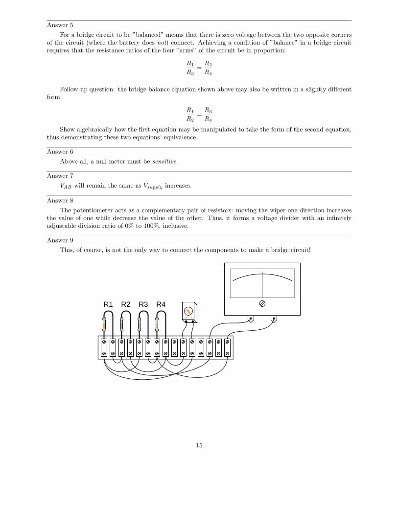
Answer 9
This, of course, is not the only way to connect the components to make a bridge circuit!
R1 R2 R3 R4
+ -
15

Answer 10
Such a bridge circuit needed to be built with three ”standard” resistors, having precisely knownresistances. At least one of these resistors needed to be adjustable, with a precision scale attached to itfor indication of its resistance at any given position. The source (”excitation”) voltage did not not have tobe precise, and the null meter only had to be sensitive and accurate at zero volts.
Answer 11
The bridge circuit will become more unbalanced, with more strain experienced by the strain gauge. Iwill not tell you what the voltmeter’s polarity will be, however!
Answer 12
If the specimen heats up, a voltage will develop between points A and B, with A being positive and B
being negative.
Answer 13
• Thermistor R1 fails open: Voltmeter ”pegs” in the negative direction.
• Thermistor R3 fails open: Voltmeter ”pegs” in the positive direction.
• Solder bridge (short) across thermistor R3: Voltmeter ”pegs” in the negative direction.
• Resistor R2 fails open: Voltmeter ”pegs” in the positive direction.
• Resistor R4 fails open: Voltmeter ”pegs” in the negative direction.
Answer 14
• Photoresistor R4 fails open: Test point B will be positive with respect to test point A (negative).
• Photoresistor R3 fails open: Test point A will be positive with respect to test point B (negative).
• Solder bridge (short) across photoresistor R4: Test point A will be positive with respect to test point B
(negative).
• Resistor R2 fails open: Test point A will be positive with respect to test point B (negative).
• Resistor R1 fails open: Test point B will be positive with respect to test point A (negative).
Answer 15
Here are two failures, although they are not the only possibilities:
• R1 could have failed shorted.• Photocell R3 could have failed open.
Answer 16
The ”dummy” gauge is attached to the specimen in such a way that it is not subjected to strain likethe ”working” gauge is. It it merely exposed to the same specimen temperature. The action of this circuitis easiest to comprehend in a scenario where there is no stress applied to the specimen, but its temperaturechanges.
Follow-up question: suppose the ”dummy” strain gauge develops an open failure, so no current maypass through it. Identify the polarity of the voltage drop that will develop across the voltmeter as a resultof this fault.
16
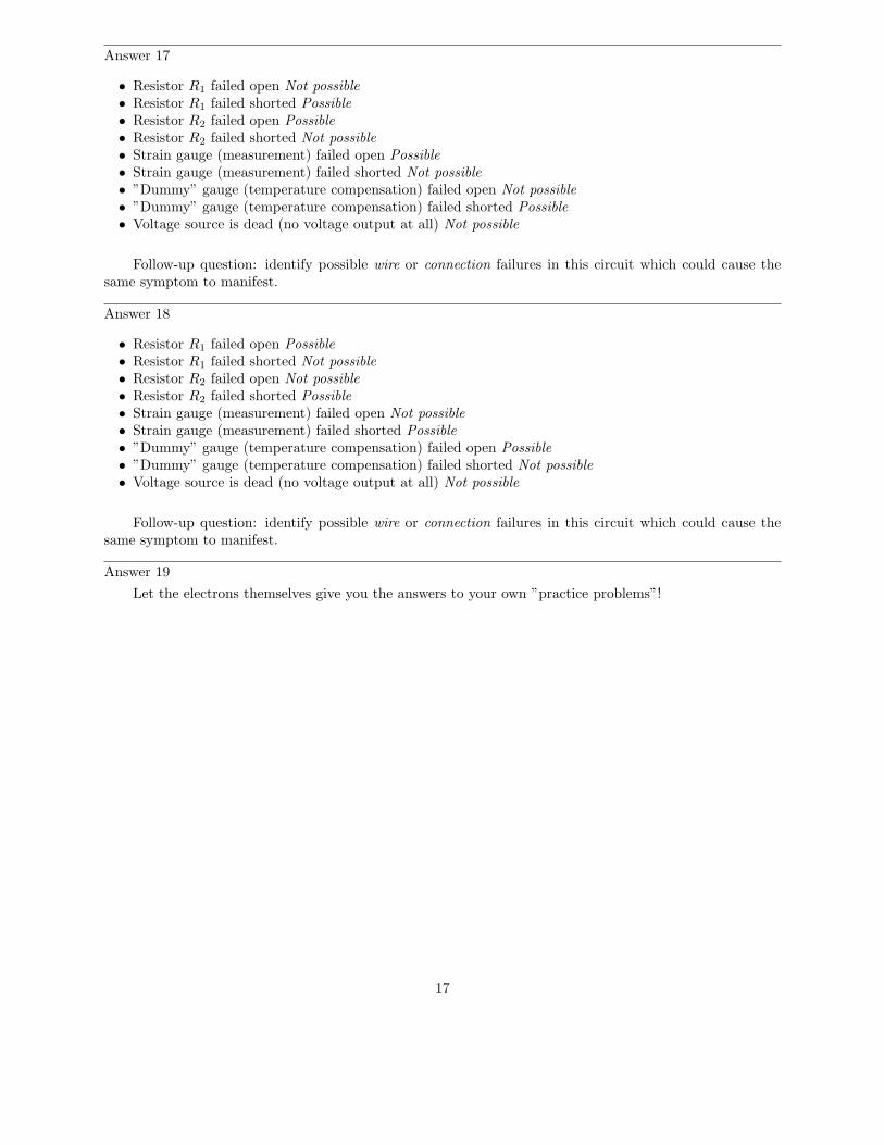
Answer 17
• Resistor R1 failed open Not possible• Resistor R1 failed shorted Possible• Resistor R2 failed open Possible• Resistor R2 failed shorted Not possible• Strain gauge (measurement) failed open Possible• Strain gauge (measurement) failed shorted Not possible• ”Dummy” gauge (temperature compensation) failed open Not possible• ”Dummy” gauge (temperature compensation) failed shorted Possible• Voltage source is dead (no voltage output at all) Not possible
Follow-up question: identify possible wire or connection failures in this circuit which could cause thesame symptom to manifest.
Answer 18
• Resistor R1 failed open Possible• Resistor R1 failed shorted Not possible• Resistor R2 failed open Not possible• Resistor R2 failed shorted Possible• Strain gauge (measurement) failed open Not possible• Strain gauge (measurement) failed shorted Possible• ”Dummy” gauge (temperature compensation) failed open Possible• ”Dummy” gauge (temperature compensation) failed shorted Not possible• Voltage source is dead (no voltage output at all) Not possible
Follow-up question: identify possible wire or connection failures in this circuit which could cause thesame symptom to manifest.
Answer 19
Let the electrons themselves give you the answers to your own ”practice problems”!
17

Notes
Notes 1
In this question, I want students to see how the voltage between the two dividers’ output terminalsis the difference between their individual output voltages. I also want students to see the notation usedto denote the voltages (use of subscripts, with an applied reference point of ground). Although voltage isalways and forever a quantity between two points, it is appropriate to speak of voltage being ”at” a singlepoint in a circuit if there is an implied point of reference (ground).
It is possible to solve for VAB without formally appealing to Kirchhoff’s Voltage Law. One way I’vefound helpful to students is to envision the two voltages (VA and VB) as heights of objects, asking thequestion of ”How much height difference is there between the two objects?”
65 ft
23 ft
Height difference = ???
The height of each object is analogous to the voltage dropped across each of the lower resistors in thevoltage divider circuits. Like voltage, height is a quantity measured between two points (the top of theobject and ground level). Also like the voltage VAB , the difference in height between the two objects is ameasurement taken between two points, and it is also found by subtraction.
Notes 2
In this question, I want students to see how the voltage between the two dividers’ output terminalsis the difference between their individual output voltages. I also want students to see the notation usedto denote the voltages (use of subscripts, with an applied reference point of ground). Although voltage isalways and forever a quantity between two points, it is appropriate to speak of voltage being ”at” a singlepoint in a circuit if there is an implied point of reference (ground).
Notes 3
The follow-up question regarding ratios is a good introduction to the fundamental principle of balancedbridge circuits. Having students work through the calculations together is a good way for them to see theprinciple for themselves.
It is also important to note in this circuit which ratios are not in agreement with each other. You can’tjust divide these four resistors into any set of two pairs and expect the ratios to equal each other! It is veryimportant for students to see this, as well.
Notes 4
This circuit may be viewed from the perspective of it being two voltage dividers, or from the perspectiveof being a current divider. Either way, it is a good exercise for you and your students to explore how itfunctions.
Notes 5
Challenge your students to write a ”balance equation” describing how the ratios must relate to eachother in order to achieve balance.
18

Notes 6
Discuss with your students the definition of ”sensitivity” with regard to meter movements, and whynull meters have to be sensitive in order for the bridge circuit to be accurately balanced. If your studentshave studied meter movement design, you may wish to challenge them with a question on exactly how a nullmeter movement might be constructed (i.e. what would have to be done to maximize its sensitivity?).
Notes 7
This question highlights another important concept of bridge circuits, namely that balance is irrespectiveof supply voltage.
Notes 8
This question showcases one more use of the potentiometer: as a voltage divider used specifically tobalance a bridge circuit for any arbitrary values of fixed resistances. If students have difficulty seeing howthis is possible, you might want to try representing the pot as a pair of fixed resistors (R3 and R4), the wiperposition determining the balance of those two resistance values (Rpot = R1 + R2).
Notes 9
Challenge your students to connect the resistors in a manner different from the diagram shown in theanswer, to make a bridge circuit. A good way to do this is to project an image of the original components(with no interconnections drawn) on a whiteboard with a video projector, then have students use dry-erasemarkers to draw the connecting wires in place. If any errors are made, they can be very easily erased withouterasing any components themselves.
Notes 10
In the past I’ve lectured on Wheatstone bridges only to find a fair number of students completelymisunderstanding the concept. The fact that a bridge circuit balances when the four arms’ resistances arein proportion is the easy part. What these students didn’t grasp is how such a bridge might be used toactually measure an unknown resistance, or why it was not possible for them to build a laboratory-usableWheatstone bridge circuit with the cheap resistors found in their parts kits.
For example, when asked how such a bridge circuit might be used, it was not unusual to hear a studentrespond that they would make one of the arms of the bridge adjustable, then measure that arm of the bridgewith their digital ohmmeter after having achieved balance in order to calculate the unknown resistance byratio. Though it may seem humorous to an instructor that someone might not realize the sheer existence ofa precise ohmmeter would render the bridge circuit obsolete, it nevertheless revealed to me how foreign theconcept of a Wheatstone bridge as a resistance measuring circuit is to students working with modern testequipment. Such a technological ”generation gap” is not to be underestimated!
In order for students to understand the practicality of a Wheatstone bridge, they need to realize thatthe only affordable calibration artifacts of the time were standard resistors and standard cells (mercurybatteries).
Notes 11
Be sure to have your students explain how they arrived at their answers for polarity across the voltmeterterminals. This is the most important part of the question!
19

Notes 12
Be sure to have your students explain how they arrived at their answers for polarity across the voltmeterterminals.
Ask your students whether or not the fact of the circuit’s sensitivity to temperature invalidates itsuse as a strain-measuring system. Is it impossible to obtain a reliable measurement of strain, if we knowtemperature also affects the circuit output voltage? How could we compensate for the effects of temperatureon the system?
Notes 13
The purpose of this question is to approach the domain of circuit troubleshooting from a perspective ofknowing what the fault is, rather than only knowing what the symptoms are. Although this is not necessarilya realistic perspective, it helps students build the foundational knowledge necessary to diagnose a faultedcircuit from empirical data. Questions such as this should be followed (eventually) by other questions askingstudents to identify likely faults based on measurements.
Notes 14
The purpose of this question is to approach the domain of circuit troubleshooting from a perspective ofknowing what the fault is, rather than only knowing what the symptoms are. Although this is not necessarilya realistic perspective, it helps students build the foundational knowledge necessary to diagnose a faultedcircuit from empirical data. Questions such as this should be followed (eventually) by other questions askingstudents to identify likely faults based on measurements.
Notes 15
Be sure to ask your students to describe failures other than the two mentioned in the answer. And,for all answers given, be sure to ask students how they determined those faults would cause the observed”negative pegging” of the voltmeter. As usual, the method of solution is much more important than theactual answer in this question.
Notes 16
Because bridge circuits are inherently differential circuits, it is possible to perform neat ”tricks” such asthis where the effects of the undesired influence (temperature) become canceled. Incidentally, the principleof cancellation by differential measurement is one that is very common in electronic systems, especiallyinstrumentation systems.
Notes 17
This question helps students build the skill of eliminating unlikely fault possibilities, allowing them toconcentrate instead on what is more likely. An important skill in system troubleshooting is the ability toformulate probabilities for various fault scenarios. Without this skill, you will waste a lot of time looking forunlikely faults, thereby wasting time.
For each fault scenario it is important to ask your students why they think it is possible or not possible.It might be that some students get the right answer(s) for the wrong reasons, so it is good to explore thereasoning for each answer.
Notes 18
This question helps students build the skill of eliminating unlikely fault possibilities, allowing them toconcentrate instead on what is more likely. An important skill in system troubleshooting is the ability toformulate probabilities for various fault scenarios. Without this skill, you will waste a lot of time looking forunlikely faults, thereby wasting time.
For each fault scenario it is important to ask your students why they think it is possible or not possible.It might be that some students get the right answer(s) for the wrong reasons, so it is good to explore thereasoning for each answer.
20

Notes 19
It has been my experience that students require much practice with circuit analysis to become proficient.To this end, instructors usually provide their students with lots of practice problems to work through, andprovide answers for students to check their work against. While this approach makes students proficient incircuit theory, it fails to fully educate them.
Students don’t just need mathematical practice. They also need real, hands-on practice building circuitsand using test equipment. So, I suggest the following alternative approach: students should build theirown ”practice problems” with real components, and try to mathematically predict the various voltage andcurrent values. This way, the mathematical theory ”comes alive,” and students gain practical proficiencythey wouldn’t gain merely by solving equations.
Another reason for following this method of practice is to teach students scientific method: the processof testing a hypothesis (in this case, mathematical predictions) by performing a real experiment. Studentswill also develop real troubleshooting skills as they occasionally make circuit construction errors.
Spend a few moments of time with your class to review some of the ”rules” for building circuits beforethey begin. Discuss these issues with your students in the same Socratic manner you would normally discussthe worksheet questions, rather than simply telling them what they should and should not do. I nevercease to be amazed at how poorly students grasp instructions when presented in a typical lecture (instructormonologue) format!
A note to those instructors who may complain about the ”wasted” time required to have students buildreal circuits instead of just mathematically analyzing theoretical circuits:
What is the purpose of students taking your course?
If your students will be working with real circuits, then they should learn on real circuits wheneverpossible. If your goal is to educate theoretical physicists, then stick with abstract analysis, by all means!But most of us plan for our students to do something in the real world with the education we give them.The ”wasted” time spent building real circuits will pay huge dividends when it comes time for them to applytheir knowledge to practical problems.
Furthermore, having students build their own practice problems teaches them how to perform primaryresearch, thus empowering them to continue their electrical/electronics education autonomously.
In most sciences, realistic experiments are much more difficult and expensive to set up than electricalcircuits. Nuclear physics, biology, geology, and chemistry professors would just love to be able to have theirstudents apply advanced mathematics to real experiments posing no safety hazard and costing less than atextbook. They can’t, but you can. Exploit the convenience inherent to your science, and get those studentsof yours practicing their math on lots of real circuits!
21