Embed Size (px)
Citation preview
UWM UITS Network Operations
Administration of Data Center Cable Plant: EMS EB. Reference: ANSI/TIA-606-A-1 (enhances and
supersedes the administration guidelines in ANSI/TIA-942) Draft 1/31/2011 Steve Bailey [email protected]
Grid Coordinates x1y1 Whenever practicable, a coordinate system (i.e. grid) should be used in the computer room and support spaces outside the computer room should be administered the same way. EMS EB is mostly on a raised floor with 2’x2’ grid with a matching 2’x2’ ceiling grid and lends it itself to use the grid system effectively. The grid identifier is determined by what grid the northwest corner of the cabinet, rack or frame is located on. x1 = The “X” axis is based on two alphabetic characters starting with “AA”. y1 = The “Y” axis is based on two numeric characters starting with “01”. Cabinet & Rack Labeling x1y1c1 We chose to add a compass direction c1 as side identifiers: N, E, S, W. This will allow the technician to quickly identify what side of the cabinet, rack or frame the connections will occur on. N = North. E = East. S = South. W = West. When the situation becomes necessary addition identifiers can be used for: A = Above ceiling grid. U = Under floor. T = Tray mounted: Above Cabinet or rack but below ceiling grid. Physical Label Characteristics for Cabinets & Racks The location identifier should be labeled in plain view on the front and rear of each cabinet and rack. Preferred locations for labels are the top and bottom on a permanent part of the cabinet or rack. Text on labels should be a font without serifs, upper case, and large enough to be easily read while standing near the cabinet or rack. Text on labels shall be machine printed, and the label color shall contrast with the surface upon which it is affixed. Equipment & Patch Panel location Identifiers x1y1c1-a1 a1 = Two numerical digits designating the location of the top of the patch panel in rack units from the bottom of the usable space in the cabinet, rack, or frame. Equipment Name
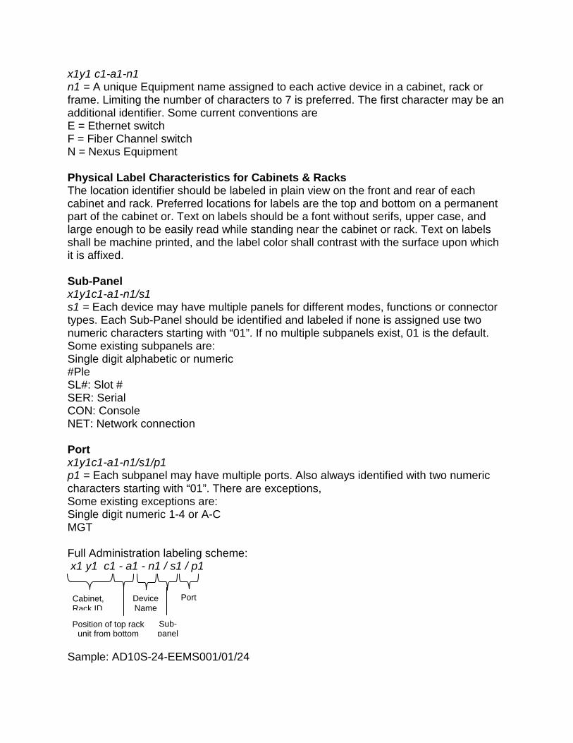
x1y1 c1-a1-n1 n1 = A unique Equipment name assigned to each active device in a cabinet, rack or frame. Limiting the number of characters to 7 is preferred. The first character may be an additional identifier. Some current conventions are E = Ethernet switch F = Fiber Channel switch N = Nexus Equipment Physical Label Characteristics for Cabinets & Racks The location identifier should be labeled in plain view on the front and rear of each cabinet and rack. Preferred locations for labels are the top and bottom on a permanent part of the cabinet or. Text on labels should be a font without serifs, upper case, and large enough to be easily read while standing near the cabinet or rack. Text on labels shall be machine printed, and the label color shall contrast with the surface upon which it is affixed. Sub-Panel x1y1c1-a1-n1/s1 s1 = Each device may have multiple panels for different modes, functions or connector types. Each Sub-Panel should be identified and labeled if none is assigned use two numeric characters starting with “01”. If no multiple subpanels exist, 01 is the default. Some existing subpanels are: Single digit alphabetic or numeric #Ple SL#: Slot # SER: Serial CON: Console NET: Network connection Port x1y1c1-a1-n1/s1/p1 p1 = Each subpanel may have multiple ports. Also always identified with two numeric characters starting with “01”. There are exceptions, Some existing exceptions are: Single digit numeric 1-4 or A-C MGT Full Administration labeling scheme: x1 y1 c1 - a1 - n1 / s1 / p1 Sample: AD10S-24-EEMS001/01/24
Cabinet, Rack ID
Position of top rack unit from bottom
Device Name
Sub-panel
Port
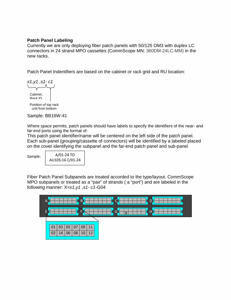
Patch Panel Labeling Currently we are only deploying fiber patch panels with 50/125 OM3 with duplex LC connectors in 24 strand MPO cassettes (CommScope MN: 360DM-24LC-MM) in the new racks. Patch Panel Indentifiers are based on the cabinet or rack grid and RU location: x1,y1 ,s1- c1 Sample: BB16W-41 Where space permits, patch panels should have labels to specify the identifiers of the near- and far-end ports using the format of: This patch panel identifier/name will be centered on the left side of the patch panel. Each sub-panel (grouping/cassette of connectors) will be identified by a labeled placed on the cover identifying the subpanel and the far-end patch panel and sub-panel Sample: Fiber Patch Panel Subpanels are treated accorded to the type/layout. CommScope MPO subpanels or treated as a “pair” of strands ( a “port”) and are labeled in the following manner: X=x1,y1 ,s1- c1-G04
Cabinet, Rack ID
Position of top rack unit from bottom
A/01-24 TO AU10S-16 C/01-24
A
E
B C D
G F H X
02
01 14
03 10
12 11
06
05 08
07
09
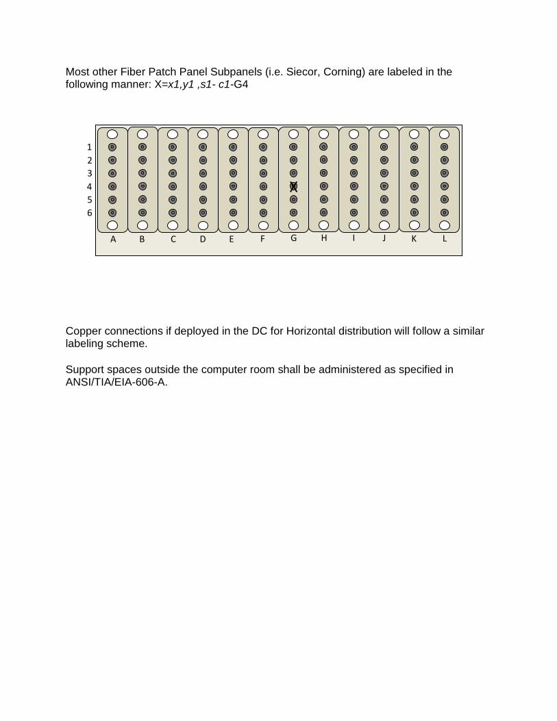
Most other Fiber Patch Panel Subpanels (i.e. Siecor, Corning) are labeled in the following manner: X=x1,y1 ,s1- c1-G4 Copper connections if deployed in the DC for Horizontal distribution will follow a similar labeling scheme. Support spaces outside the computer room shall be administered as specified in ANSI/TIA/EIA-606-A.
A B D C G F E I H J L K
1 2 3 4 5 6
X