Embed Size (px)
Citation preview
DC Motors, Stepper Motors, H-bridges
• DC Motors• Stepper Motors• Motor Control Circuits
– Relays– H-bridges
AC versus DC Motors
• AC motors are not very flexible w/o a transmission– They can only turn in one direction– The speed is controlled by the design of the motor and
the frequency of the AC current source (60Hz)
• DC Motors can be operated more flexibly– They can turn in either direction based on the polarity
of the applied voltage– The speed is controlled by the magnitude of the voltage
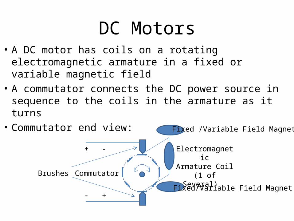
DC Motors• A DC motor has coils on a rotating electromagnetic
armature in a fixed or variable magnetic field• A commutator connects the DC power source in
sequence to the coils in the armature as it turns• Commutator end view:
+ -
- +
Brushes Commutator
ElectromagneticArmature Coil(1 of Several)
Fixed /Variable Field Magnet
Fixed/Variable Field Magnet
DC Motors
• A continuous voltage across the brushes will keep the motor turning in either one direction or the other depending on the polarity– A higher voltage across the brushes will make the
motor turn faster– A lower voltage across the brushes will make the
motor turn slower
• The commutator sparks as it turns creating EMI or possible explosion hazard
Stepper Motors
• A stepper motor is a DC motor that has fixed magnets on the armature
• It does not use a commutator to automatically energize/de-energize different magnetic coils
• The ends of the coil windings in the field are alternately energized and de-energized by an external control circuit in a desired sequence
• The order and dwell time of the voltage to each coil controls the direction and the speed
Stepper Motors
• A stepper motor can be held in a fixed position by pausing the sequence and keeping one coil energized for the duration of the hold time
• Hence, a stepper motor can be used in similar applications as a servomotor (studied in CS341)– It can be moved to and held in a desired position– It can be rotated continuously at a controlled speed
• The control is all externally implemented
Types of Stepper Motors
• Many possible geometric arrangements of the:– Fixed magnets on the armature– Electromagnetic coils in the field around the armature
• References:http://homepage.cs.uiowa.edu/~jones/step/types.html
• Our Mercury Motor is a Bipolar Stepper Motor
Stepper Motors - Heat
• Stepper motors are designed to operate at a high temperature and can get hot (~ 80 deg C)
• If this causes a problem, try the following:– Lower the voltage (But I found the Mercury motor
will not step/hold reliably at 9 VDC versus 12 VDC)– Turn off the power to the coils when not in use
(Expect that the motor will slip out of position)– Mount the motor on a heat sink to dissipate heat– Use a fan to create air flow over motor / heat sink
Motor Control Circuits
• A motor control circuit:– Provides power to the motor coils in either polarity– Allows the external logic to control direction/speed
• There are two basic types of motor controllers– Electromechanical relay based controllers– Semiconductor based controllers (H-bridges)
• Each type has its advantages and disadvantages• We’ll use our elevator motors as an example
Relay Motor Control Circuit
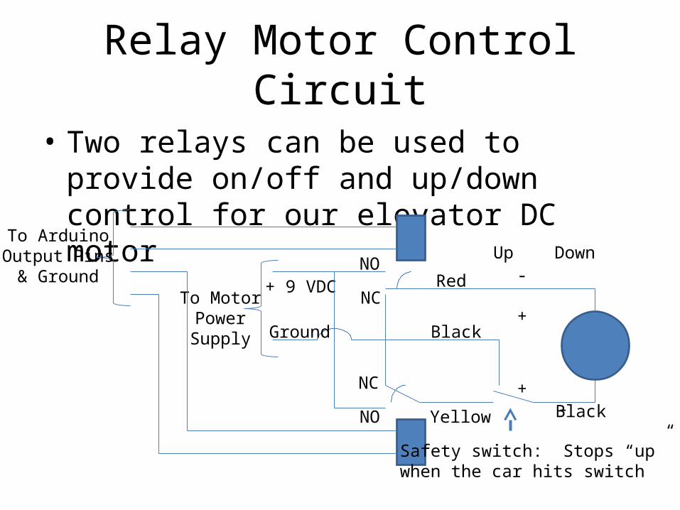
• Two relays can be used to provide on/off and up/down control for our elevator DC motor
Ground
+ 9 VDC- +
+ -
To ArduinoOutput Pins& Ground
To MotorPowerSupply
Red
Black
BlackYellow
Safety switch: Stops “up”when the car hits switch
NO
NO
NC
NC
Up Down
Relay Motor Control Circuit
• Advantages– Uses simple, robust electromechanical devices– Can handle high voltages and large currents
• Disadvantages– Requires periodic maintenance (cleaning contacts)– Relatively slow due to inertia in mechanical parts– Contact make/break/bounce sparks creating EMI or
possible explosion hazard
• Example: Used under the hood in cars
Relay Motor Control Circuit
• A DC motor such as the drive motor for our elevator system requires one circuit per motor– The direction is determined by one relay or the other
being turned on - closing normal open (NO) contact
• A bipolar stepper motor such as the Mercury Motor requires two circuits per motor– Each coil is turned on and off in a selected direction in
sequence to change the position continuously– One coil can be left on in a selected direction to hold in a
desired position
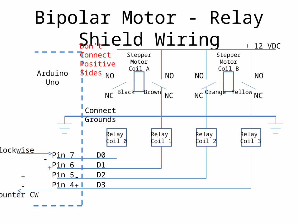
Bipolar Motor - Relay Shield Wiring
ArduinoUno
Don’tConnectPositiveSides
+ 12 VDC
NC NC NC NC
NONONONO
ConnectGrounds
Black Brown Orange Yellow
StepperMotorCoil A
StepperMotorCoil B
Pin 7 D0Pin 6 D1Pin 5 D2Pin 4 D3
RelayCoil 0
RelayCoil 1
RelayCoil 2
RelayCoil 3
Clockwise+ -- + + - - +Counter CW
H-bridge Motor Control Circuit
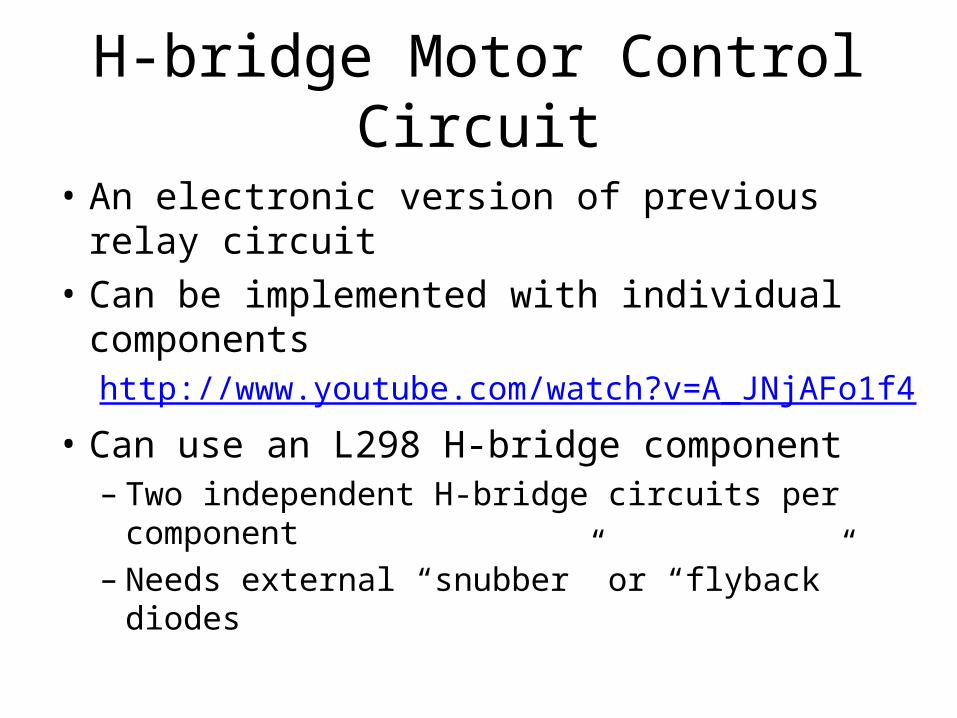
• An electronic version of previous relay circuit• Can be implemented with individual components
http://www.youtube.com/watch?v=A_JNjAFo1f4
• Can use an L298 H-bridge component– Two independent H-bridge circuits per component– Needs external “snubber” or “flyback” diodes
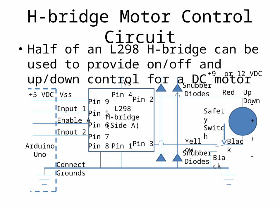
H-bridge Motor Control Circuit• Half of an L298 H-bridge can be used to provide
on/off and up/down control for a DC motor
- +
+ -
L298H-bridge(Side A)
+9 or 12 VDC
ConnectGrounds
SnubberDiodes
SnubberDiodes
ArduinoUno
Pin 2
Pin 3Pin 7
Pin 6
Pin 5
Pin 9Pin 4
Pin 8
+5 VDC
Pin 1
Input 1
Input 2
Enable A
Vss
VsUp DownRed
Yellow Black
Black
SafetySwitch
H-bridge Motor Control Circuit
• Advantages– No periodic maintenance is required (no contacts)– Fast switching speed available (limited by motor)– No EMI or possible explosion hazard due to sparks
• Disadvantages:– Limited voltage and current handling capacity– Vulnerable to EMI/EMP or damage due to electrical
transients (may need metal shielded container and “snubber” or “flyback” diodes)

H-bridge Motor Control Circuit
• A DC motor such as our elevator system drive motor requires one H-bridge per motor– The direction is determined by the inputs (1 or 2)– The motor can be turned on and off by the Enable A
• A bipolar stepper motor such as the Mercury Motor requires two H-Bridge circuits per motor– The direction is determined by the ordering of the
logic signals to the inputs (1, 2, 3, or 4)– The speed is controlled by the speed of sequencing
H-bridge Motor Control Circuit
• The Motor Shield provides uses both halves of an L298 component – one to control each coil of the stepper motor
• It is an electronic version of the Relay Shield diagram shown earlier
• It includes the “snubber” diodes on the board