Embed Size (px)
Citation preview

Security and Virtualization in the Data Center
Cisco Validated Design
May 6, 2009
ContentsIntroduction 2
Audience 2
Document Objectives 2
Overview 3
Solution Topology 4
Required Hardware/Software 5
Design Details 7
Design Goals 7
Data Center Core 8
IP Routing Design and Recommendations 8
Data Center Aggregation Layer 10
IP Routing Design and Recommendations 10
Aggregation Layer and Firewalls 13
Services Layer 17
Server Load Balancing 18
Web Application Security 19
Cisco ACE and Web Application Firewall Deployment 20
IPS Deployment 22
Caveats 24
Cisco ACE, Cisco ACE Web Application Firewall, Cisco IPS Traffic Flows 25
Access Layer 26
Corporate Headquarters:
Copyright © 2009 Cisco Systems, Inc. All rights reserv
Cisco Systems, Inc., 170 West Tasman Drive, San Jose, CA 95134-1706 USA

Introduction
Recommendations 27
Virtual Access Layer 27
Server Virtualization and Network Security 27
Infrastructure Security Recommendations 36
Infrastructure Device Access 36
Out-of-Band Management Interface Hardening 37
NetFlow and Syslog 38
Network Time Protocol 39
Attack Prevention and Event Correlation Examples 39
Virtual Context on ASA for ORACLE DB Protection 39
Web Application Firewall Preventing Application Attacks 41
Using Cisco ACE and Cisco ACE WAF to Maintain Real Client IP Address as Source in Server Logs 43
Using IDS for VM-to-VM Traffic Visibility 45
Using IDS and Cisco Security MARS for VM Traffic Visibility 46
Threats Mitigated 48
Alternate Topology #1 49
Conclusion 50
Additional References 50
Cisco Validated Design 51
Introduction
AudienceThis document is intended for use by network engineers and architects considering the integration of security into a data center infrastructure within a virtualized environment.
Document ObjectivesThe purpose of this document is to provide detailed design recommendations for integrating network security in the Enterprise intranet data center. This guide provides an overview of network and security device virtualization, describes how these features can be used for a more seamless integration of security, and summarizes considerations for securing a virtualized server environment.
The designs in this document provide examples of adding scalable security services to 10 Gigabit-based data center architectures. The products used to illustrate design options in this document include the following Cisco products:
• Nexus 7000
• Nexus 5000
• Nexus 1000V
2Security and Virtualization in the Data Center
OL-19350-01
Overview
• Catalyst 6500
• ASA 5580
• IPS 4270
• Application Control Engine (ACE) Load Balancer
• ACE Web Application Firewall (WAF)
• Security Monitoring, Analysis and Response System (Cisco Security MARS)
OverviewThreats facing today IT security administrators have grown from the relatively trivial attempts to wreak havoc on networks into sophisticated attacks aimed at profit and the theft of sensitive corporate data. Implementation of robust data center security capabilities to safeguard sensitive mission-critical applications and data is a cornerstone in the effort to secure enterprise networks.
The data center security challenges does not stop there. New application rollouts, virtualization, and an increasingly transparent perimeter are converging to drive an evolution in the requirements for data center security architectures.
Application rollouts bring there own set of challenges for securing communications and applying security policy—couple this with a virtualized environment and the challenge of policy enforcement and visibility increases many times over.
Traditionally, the perimeter has been the proverbial shield to stop malicious and unwanted outside traffic from leaking into the Enteprise network. Creating a secure perimeter is still valid and essential in defending against attacks and providing traffic filtering. But the amount and type of traffic entering the enterprise network has increased and continues to do so. Extranet connections for business partners, vendor connections, supply chain transactions, and digital communications all required more openings to be created at the perimeter to allow communication. Permitting these business-driven openings creates greater opportunities for attack and elevates the risk to a network.
In addition, attack vectors have moved higher in the stack to subvert network protection and aim directly at applications. HTTP-, XML-, and SQL-based attacks are useful efforts for most attackers because these protocols are usually allowed to flow through the enterprise network and enter the intranet data center.
Virtualization is driving change in the way data centers are being architected. Server virtualization is becoming a prevalent tool for consolidation, power savings, and cost reduction. It is also creating new challenges for infrastructure and security teams to be able to provide consistent levels of isolation, monitoring, and policy enforcement-similar to what is available for physical servers and systems today.
Device virtualization is providing new design opportunities and options for creating flexible data center architectures. Features that provide control plane and data plane isolation are offering a multitude of design options for device placement, Layer-2 and Layer-3 designs, and service integration.
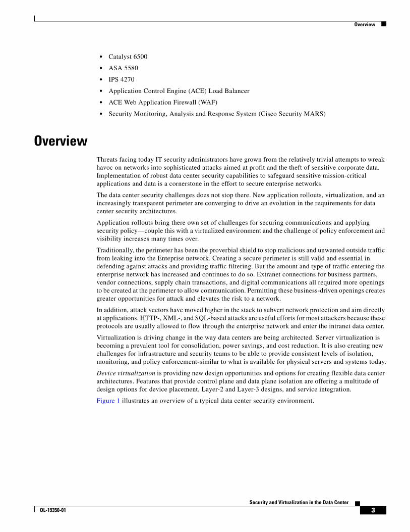
Figure 1 illustrates an overview of a typical data center security environment.
3Security and Virtualization in the Data Center
OL-19350-01

Overview
Figure 1 Data Center Security Overview
Security for virtualization and virtualized security are not one in the same. Both are key for providing policy enforcement for these new architectures. Both topics are discussed in this document with an emphasis placed on design and deployment.
Solution TopologyThe architectures discussed in this document are based on the Cisco data center design best practice principles. This multi-layered data center architecture is comprised of the following key components: core, aggregation, services, and access. This architecture allows for data center modules to be added as the demand and load increases. The data center core provides a Layer-3 routing module for all traffic in and out of the data center. The aggregation layer serves as the Layer-3 and Layer-2 boundary for the data center infrastructure. In these design, the aggregation layer also serves as the connection point for the primary data center firewalls. Services such as server load balancers, intrusion prevention systems, application-based firewalls, network analysis modules, and additional firewall services are deployed at the services layer. The data center access layer serves as a connection point for the serverfarm. The virtual-access layer refers to the virtual network that resides in the physical servers when configured for virtualization.
Data Center Firewalls
Initial filter for DC ingressand egress traffic. VirtualContext used to split policiesfor server-to-server filtering
DC Core
Data Center Aggregation
Security Services Layer
Infrastructure Security
Data Center Services Layer
Access Layer
Virtual Access Layer
2265
59VM VM VM
VM VMVM
L2 Security features are available within thephysical server for each VM. Features includeACLs, CISF, Port Security, Netflow ERSPAN,QoS, CoPP, VN Tag
ACLs, CISF, PortSecurity, QoS, CoPP,VN Tag
IPS/IDS: provide traffic analysis and forensics
Network Analysis: providetraffic monitoring and dataanalysis
Infrastructure Security featuresare enabled to protect device,traffic plane, and control plane.
VDC provides internal/externalsegmentation
XML Gateway: protectand optimize Web-basedservices
Additional FirewallServices for Server Farmspecific protection
Server Load Balancingmasks servers andapplications
Application Firewallmitigates XSS, HTTP,SQL, XML based attacks
4Security and Virtualization in the Data Center
OL-19350-01

Overview
A visual overview of this topology is provided in Figure 2.
Figure 2 Solution Topology
This document provides information about the integration of security services within the data center infrastructure. The Layer-2 and Layer-3 infrastructure details are highlighted from a security connection and traffic flow standpoint, but are not be covered in great depth in this document. There are several Cisco Validated Design (CVD) guides that offer a great amount of detail on the underlying data center infrastructure.
For more information on the integration of services with a Cisco Nexus 7000, refer to Implementing Nexus 7000 in the Data Center Aggregation Layer with Services at the following URL:
http://www.cisco.com/en/US/docs/solutions/Enterprise/Data_Center/nx_7000_dc.html
For more information on the integration of dedicated services switches, refer to Data Center Service Integration: Service Chassis Design Guide at the following URL:
http://www.cisco.com/en/US/docs/solutions/Enterprise/Data_Center/dc_servchas/service-chassis_design.html
Required Hardware/SoftwareTable 1 summarizes the required hardware and software elements used to illustrate the data center security integration solution described in this document.
Catalyst6500
Catalyst6500
Nexus7000
ASA5580
CoreLayerAggregation
Layer
ServicesLayer
ASA5580
Nexus7000
Catalyst6500
Catalyst4900s
Catalyst6500 VSS
Catalyst 3100 VBS
Catalyst6500s
Nexus5000s
ACE WAF
IDS/IPS IDS/IPS
ACEModule
ACEModule
2265
30
AccessLayer
5Security and Virtualization in the Data Center
OL-19350-01

Overview
Table 1 Solution Hardware and Solution Software Components
Platforms, Line Cards, End Points within Role Releases
Core Router/Switch Catalyst 6500 Series
WS-X6724-SFP
WS-6704-10GE
VS-S720-10G
12.2(33)SXH2
Aggregation Router /Switch Nexus 7000 Series
N7K-M132XP-12
N&K-M148GT-11
N7K-SUP1
4.1(2)
Services Layer Switch Catalyst 6500 Series
VS-S720-10G
WS-6708-10GE
WS-6748-GE-TX
ACE20-MOD-K9
WS-SVC-NAM-2
ASA5580-40
IPS4270-20-k9
ACE-XML-K9
12.2(33)SXI
A2(1.3)
4.0(1)
8.1(2)
6.2(1)E3
6.0.2-2008-09-15T22
Access Layer Switches Catalyst 6500 Series
WS-6708-10GE
WS-6704-10GE
WS-SVC-NAM-2
VS-S720-10G
WS-X6748-GE-TX
WS-C4900M
WS-X4904-10GE
WS-X4920-GB-RJ45
N5k-C5020P-BF
N5K-M1404
WS-CBS3120G-S
WS-CBS3120X-S
Nexus 1000V
12.2(33)SXI
4.0(1)
12.2(46)SG
4.0(1a)N1(1)
12.2(40)EX1
12.2(40)EX1
4.0(1a)S1(0.14
Server Environments HP DL380 G5
HP DL380 G4
VMWare 3.5u2 and 4.0(RC)
Windows Server 2003
Oracle Linux 5.2 (Carthage)
6Security and Virtualization in the Data Center
OL-19350-01

Design Details
Design DetailsThis section presents the key design concepts addressed in this document and describes the following details for the integrated data center security solution addressed:
• Design Goals, page 7
• Data Center Core, page 8
• Data Center Aggregation Layer, page 10
• Services Layer, page 17
• Access Layer, page 26
• Virtual Access Layer, page 27
• Infrastructure Security Recommendations, page 36
• Attack Prevention and Event Correlation Examples, page 39
• Threats Mitigated, page 48
• Alternate Topology #1, page 49
Design GoalsData center design is an act of constant planning. The core infrastructure design, power and cooling, cabling, and location must be carefully analyzed prior to installation and reviewed in an ongoing basis. The services in a data center are often seen as bolt-on additions that are simply connected when needed. The concept of add-on services is a good one and in fact services should be able to be added as requirements change and the data center grows. But when these devices are in the traffic path for critical applications and data, careful thought must be given to how they connect, where they connect, how they scale, and how they handle failure.
Security is often considered as an after-thought in many architecture designs. In reality, it is easier in the long run if security is considered as part of the core requirements—and not as an add-on. But this depends on several business-related factors and the drivers for security in the data center might change over time due to new application rollouts, compliance requirements, acquisitions, and—not the least of which—security breeches.
This document focuses on three areas of data center security: isolation, policy enforcement, and visibility. These can be defined as follows:
• Isolation—Isolation can provide the first layer of security for the data center and serverfarm. Depending on the goals of the design it can be achieved through the use of firewalls, access lists, Virtual Local Area Networks (VLAN), virtualization, and/or physical separation. A combination of these can provide the appropriate level of security enforcement to the serverfarm applications and services.
• Policy Enforcement—There is no shortage on the variety of traffic flows, protocols, and ports required to operate within the data center. Traffic flows can be sourced from a variety of locations, including client to server requests, server responses to these requests, server originated traffic, and server-to-server traffic. Because of the amount of traffic flows and the variety of sources, policy enforcement in the data center requires a considerable amount of up-front planning—couple this with a virtualized environment and the challenge of both policy enforcement and visibility becomes greater.
7Security and Virtualization in the Data Center
OL-19350-01

Design Details
• Visibility—Data centers are becoming very fluid in the way they scale to accommodate new virtual machines and services. Server virtualization and technologies, such as VMotion, allow new servers to be deployed and to move from one physical location to another with little requirement for manual intervention. When these machines move and traffic patterns change, a security administration challenge can be created in terms of maintaining visibility and ensuring security policy enforcement.
The security services and examples in this document have been integrated into the example architecture defined here with these three considerations in mind. Because security models can differ depending on the business goals of the organization, compliance requirements, the serverfarm design, and the use of specific features (such as device virtualization), there is no magic blueprint that covers all scenarios. However, the basic principles introduced in this document for adding security to the data center architecture can apply to other environments.
Data Center Core The data center core module provides Layer-3 connectivity between the data center and the campus network. The core is a centralized Layer-3 routing module in which one or more data center aggregation layers connect. This usually serves as the initial entry point from the campus network into the data center infrastructure.
IP Routing Design and Recommendations
Routing adjacencies from the core are formed to the campus core and the data center aggregation switches. In this design, the data center core is configured for Enhanced Interior Gateway Routing Protocol (Enhanced IGRP) to communicate with the campus core and the network with Open Shortest Path First (OSPF) to communicate with the data center. The core routers are redistributing Enhanced IGRP and OSPF. Figure 3 illustrates an example data center core routing design.
8Security and Virtualization in the Data Center
OL-19350-01

Design Details
Figure 3 Data Center Core Routing Design
Routing is critical for the enterprise network and for access to data center services. Routing can be compromised either intentionally or unintentionally in several ways.
Incorrect neighbor peering leads to an injection of incorrect routes; this could also lead to routing loops and denial-of-service for the data center. To prevent this problem there are several measures that should be incorporated as part of the data center routing design. These measure include the following:
• Route peer authentication
• Route filtering
• Log neighbor changes
Authenticating peers before establishing a routing adjacency will help prevent incorrect neighbor peering that could lead to routing loops, routing manipulation, and service interruption. It is important to also correctly filter routes. It might not always be desirable to have all routes populated on all data center devices. In the example illustrated in Figure 3, the Not-So-Stubby Area (NSSA) area is being used to limit the amount of routes being propagated inside the data center. It is also important to properly filter routes when performing any routing redistribution. This means properly setting metrics and filtering specific routes from being forwarded during the redistribution between two routing protocols; this prevents routing loops from occurring. If not filtered correctly, routes being exchanged between protocols with different administrative distances and metrics can cause the route to be repeatedly redistributed and re-advertised via each protocol. Logging all neighbor changes provides visibility into the occurrence of peering problems and alerts administrators to possible issues.
The following output provides an example of the authentication configurations being for both EIGRP and OSPF.
Po9910.8.162.3/2410.8.152.3/24
10.8.0.x/24
.1 .1
.2 .2
10.8
.1.x
/24
10.8
.2.x
/24
RID:8.8.8.1 RID:8.8.8.2
RID:3.3.3.1 RID:3.3.3.2
10.8.162.2/2410.8.152.2/24
OSPF Area 0
N7k1-VDC1
DataCenterCore1
DataCenterCore2
N7k2-VDC1
.1 .210.8.3.x/24
.24 .26
.25 .2710
.242
.10.
x/31
10.2
42.1
0.x/
31EIGRP 1
CampusCore1
CampusCore2
(SVI 3)(SVI 3)
2265
60
.1 .2
9Security and Virtualization in the Data Center
OL-19350-01

Design Details
Enhanced IGRP Interface Configuration
ip authentication mode eigrp 1 md5 ip authentication key-chain eigrp 1 eigrp-chainlogging event link-status
OSPF Global Configuration
router ospf 8area 0 authentication message-digestpassive-interface defaultInterface X/Xip ospf authentication message-digestip ospf authentication-key 3 9125d59c18a9b015logging event link-status
For more information on secure routing, refer to the Network Security Baseline document located at the following URL:
http://www.cisco.com/en/US/docs/solutions/Enterprise/Security/Baseline_Security/securebasebook.html
Data Center Aggregation LayerThe aggregation switches used in this design are a pair of Cisco Nexus 7000 Series switches. They serve as a high performance 10-Gigabit aggregation point for data center traffic and services.
The Cisco Nexus 7000 introduces the concept of Virtual Device Context (VDC). The VDC feature allows for the virtualization of the control plane, data plane, and management plane of the Cisco Nexus 7000. From a security standpoint this virtualization capability can provide an enhanced security model. Because the VDCs are logically separate devices, each can have different access, data, and management policies defined.
Note In-depth details on VDCs and how they fit into the overall data center design can be found in the data center best practice guides previously referenced. This document focuses on the integration of VDCs and security services.
The design described in this document includes a single pair of data center aggregation switches divided into four separate logical switches. Two VDCs have been created in each Cisco Nexus 7000—VDC1 and VDC2. This provides an inside and outside isolation point at the data center aggregation layer. The outside VDC provides Layer-3 connectivity to the data center core. The inside VDC provides Layer-2 connectivity to the data center services and serverfarm. In order for traffic to flow from the outside VDC to the inside VDC, the traffic must either be routed or bridged through an external device. In this design, traffic forwarding between VDC1 and VDC2 is performed by external firewalls.
IP Routing Design and Recommendations
The IP routing design provides isolation. The outside VDC is a member of OSPF Area 0 and is a neighbor of the data center core routers. This allows routes to propagate in and out of the data center and to the rest of the enterprise network. The inside VDC is configured as a NSSA area in OSPF. The inside
10Security and Virtualization in the Data Center
OL-19350-01

Design Details
VDC only receives a default route from the outside. This prevents the entire routing table from propagating farther into the data center. Figure 4 illustrates an example routing design based on these principles.
Figure 4 Routing Topology
The following command listing illustrates the Cisco Nexus 7000 VDC1 OSPF configuration. VLAN 161 is carried to the outside interface of the Cisco ASA firewall.
The following is the Nexus 7000 configuration for VLAN 161 on VDC1:
interface Vlan161 no shutdown ip address 10.8.162.3/24 ip ospf authentication message-digest ip ospf message-digest-key 1 md5 3 b2255cb5a7107f1b ip router ospf 8 area 0.0.0.81 ip pim sparse-mode ip igmp version 3 hsrp 1 authentication text c1sc0 preempt delay minimum 180 priority 20 forwarding-threshold lower 0 upper 0 timers 1 3 ip 10.8.162.1
The following is the routing configuration on Nexus 7000 VDC1:
router ospf 8 router-id 3.3.3.1 area 81 nssa
ACE2
ASA2
ASA2
ASA1
Po99
Po99
10.8.152.610.8.152.5
10.8.162.3/2410.8.152.3/24
10.8.0.x/24.1 .2
.1 .1
.2 .2
10.8
.1.x
/24
10.8
.2.x
/24
RID:8.8.8.1 RID:8.8.8.2
RID:3.3.3.1 RID:3.3.3.2
10.8.162.2/2410.8.152.2/24
OSPF NSSA Area 81
OSPF Area 0
ASA1
ACE1
SS2SS1 N7k1-VDC2 N7k2-VDC2
N7k1-VDC1
Cat6k Cat6k
N7k2-VDC1
VRF1 VRF2 VRF1VRF2
10.8.162.610.8.162.5
.1 .210.8.3.x/24 (SVI 3)(SVI 3)
RID:4.4.4.1 RID:5.5.5.1 RID:4.4.4.2 RID:5.5.5.2
2265
31
VLAN161
VLAN162
VLAN164
VLAN162151
152
11Security and Virtualization in the Data Center
OL-19350-01

Design Details
default-information originate area 0.0.0.0 range 10.8.0.0/24 area 0.0.0.0 range 10.8.1.0/24 area 0.0.0.0 range 10.8.2.0/24 area 0.0.0.0 range 10.8.3.0/24 area 0.0.0.81 range 10.8.128.0/18 area 0.0.0.0 authentication message-digest area 0.0.0.81 authentication message-digest timers throttle spf 10 100 5000 timers throttle lsa router 1000 timers throttle lsa network 1000 auto-cost reference-bandwidth 10000
The following is the Cisco ASA configuration for VLAN 161 and 162 on context 1 (dca-vc1).
context dca-vc1 allocate-interface Management0/0.1 allocate-interface TenGigabitEthernet5/0.161 outside allocate-interface TenGigabitEthernet5/1.162 inside config-url disk0:/dca-vc1.cfg join-failover-group 1
The following illustrates interface VLAN 164 configuration on the Cisco Nexus 7000 VDC2. VLAN 164 resides on the inside of the service chain after and it is carried from the services switch to the Nexus 7000 VDC2. Details on VLAN 164, how the service VLANs are bridged, and the service flows will be discussed in the next section.
interface Vlan164 no shutdown vrf member servers1 ip address 10.8.162.5/24 ip ospf authentication message-digest ip ospf message-digest-key 1 md5 3 b2255cb5a7107f1b ip router ospf 8 area 0.0.0.81 ip pim sparse-mode ip igmp version 3 hsrp 2 authentication text c1sc0 preempt delay minimum 180 priority 20 forwarding-threshold lower 0 upper 0 timers 1 3 ip 10.8.162.7
The following illustrates the OSPF configuration on the Cisco Nexus 7000 VDC2 for VRF Server1 and VRF Server2.
router ospf 8 vrf servers1 router-id 4.4.4.1 area 81 nssa area 0.0.0.81 authentication message-digest timers throttle spf 10 100 5000 timers throttle lsa router 1000 timers throttle lsa network 1000 vrf servers2 router-id 5.5.5.1 area 81 nssa area 0.0.0.81 authentication message-digest timers throttle spf 10 100 5000 timers throttle lsa router 1000 timers throttle lsa network 1000
dca-n7k1-vdc2# sh ip routeIP Route Table for VRF "default"
12Security and Virtualization in the Data Center
OL-19350-01

Design Details
'*' denotes best ucast next-hop '**' denotes best mcast next-hop'[x/y]' denotes [preference/metric]
0.0.0.0/32, 1 ucast next-hops, 0 mcast next-hops *via Null0, [220/0], 4w2d, local, discard10.8.3.0/24, 1 ucast next-hops, 0 mcast next-hops, attached *via 10.8.3.3, Vlan3000, [0/0], 2w4d, direct10.8.3.0/32, 1 ucast next-hops, 0 mcast next-hops, attached *via 10.8.3.0, Null0, [0/0], 2w4d, local! <...>
The Nexus 7000 VDC1 and VDC2 OSPF interfaces are peering through the service VLANs to establish neighbor relationships.
Just as with the data center core, protective measures should be incorporated as part of the data center aggregation layer routing design. These action include the following:
• Route peer authentication
• Route filtering
• Log neighbor changes
Aggregation Layer and Firewalls
Using Device Virtualization to Integrate Security
The aggregation layer provides an excellent filtering point and first layer of protection for the data center. This layer provides a building block for deploying firewall services for ingress and egress filtering. The Layer-2 and Layer-3 recommendations for the aggregation layer also provide symmetric traffic patterns to support stateful packet filtering.
Because of the performance requirements, this design uses a pair of Cisco ASA 5580 firewalls connected directly to the aggregation switches. The Cisco ASA5580's meet the high performance data center firewall requirements by providing 10-Gbps of stateful packet inspection.
In this design, the Cisco ASA firewalls are configured in transparent mode. This means the firewalls are configured in a Layer-2 mode and will bridge traffic between interfaces. The Cisco ASA firewalls have been configured for multiple contexts using the virtual context feature. This virtualization feature allows the firewall to be divided into multiple logical firewalls each supporting different interfaces and policies.
Note The modular aspect of this design allows additional firewalls to be deployed at the aggregation layer as the serverfarm grows and the performance requirements increase.
The firewalls are configured in an active-active design. This design allows load sharing across the infrastructure based on the active Layer-2 and Layer-3 traffic paths. Each firewall has been configured for two virtual contexts. Virtual context 1 is active on the ASA 1 and virtual context 2 is active on ASA 2. This corresponds to the active Layer-2 spanning tree path and the Layer-3 Hot Standby Routing Protocol (HSRP) configuration.
An example of each firewall connection is shown in Figure 5.
13Security and Virtualization in the Data Center
OL-19350-01

Design Details
Figure 5 Cisco ASA Virtual Contexts and Cisco Nexus 7000 Virtual Device Contexts
Virtual Context Details
The contexts on the firewall provide different forwarding paths and policy enforcement depending on the traffic type and destination. Incoming traffic that is destined for the data center services layer (ACE, WAF, IPS, and so on) is forwarded from VDC1 on the Cisco Nexus 7000 to virtual context 1 on the Cisco ASA over VLAN 161. The inside interface of virtual context 1 is configured on VLAN 162. The Cisco ASA filters the incoming traffic and then in this case bridges the traffic to the inside interface on VLAN 162. VLAN 162 is carried to the services switch where traffic has additional services applied. The same applies to virtual context 2 on VLANs 151 and 152. This context is active on ASA 2. The output below shows each context configuration and the current failover state.
The contexts are created under the system management context and the interface pairings are assigned.
context dca-vc1 allocate-interface Management0/0.1 allocate-interface TenGigabitEthernet5/0.161 outside allocate-interface TenGigabitEthernet5/1.162 inside config-url disk0:/dca-vc1.cfg join-failover-group 1
context dca-vc2 allocate-interface Management0/0.2 allocate-interface TenGigabitEthernet7/0.151 outside allocate-interface TenGigabitEthernet7/1.152 inside config-url disk0:/t join-failover-group 2
The configuration can also been seen by logging into the Cisco Adaptive Security Device Manager (ASDM) management GUI. See Figure 6.
Po99
Po99
2265
61
ASA1
10.8.152.5
161
162
151
15210.8.152.3
10.8.162.3
ASA2
VRF1
SVI-161
SVI-151
VRF2
10.8.152.6
10.8.152.2
10.8.162.2
N7k2-VDC2
N7k2-VDC1
VRF1
SVI-161
SVI-151
VRF2
hsrp.7
hsrp.1
hsrp.7
ASA2
ASA2
N7k1-VDC2
N7k1-VDC1
10.8.162.5 10.8.162.6
hsrp.1
14Security and Virtualization in the Data Center
OL-19350-01

Design Details
Figure 6 Cisco ASDM Screenshot of Virtual Contexts
Note There are three virtual device contexts shown in the Cisco ASDM output. The third context (dca-vc3) is described in the “Virtual Context on ASA for ORACLE DB Protection” section on page 39.
To view the command line configuration, log into the ASA and issue the changeto command to view each device context. The following is an overview of the DCA-VC1 virtual context interface configuration:
firewall transparenthostname dca-vc1enable password 8Ry2YjIyt7RRXU24 encryptedpasswd 2KFQnbNIdI.2KYOU encryptednames!interface Management0/0.1 mac-address 00a0.c900.0102 nameif management security-level 100 ip address 172.26.146.x 255.255.254.0 management-only!interface outside nameif north security-level 100!interface inside nameif south security-level 0
Issue the changeto command to view another context. The following is an overview of the DCA-VC2 virtual context interface configuration:
firewall transparenthostname dca-vc2enable password 8Ry2YjIyt7RRXU24 encryptedpasswd 2KFQnbNIdI.2KYOU encryptednames
15Security and Virtualization in the Data Center
OL-19350-01

Design Details
!interface Management0/0.2 nameif management security-level 100 ip address 172.26.146.x 255.255.254.0 management-only!interface outside nameif north security-level 100!interface insidenameif southsecurity-level 0
The following show failover command output example illustrates the current failover state for context 1 and context 2.
This host: Primary Group 1 State: Active Active time: 1010495 (sec) Group 2 State: Standby Ready Active time: 281093 (sec)
Deployment Recommendations
The firewalls enforce access policies for the data center. Most, if not all, of the requests for the enterprise data center will be sourced from the internal network. The internal firewalls provide a line of defense for the data center assets. Using a multi-layered security model to provide protection for the enterprise data center from internal or external threats is a best practice for creating a multi-layered security model.
The firewall policy will differ based on the organizational security policy and the types of applications deployed. In most cases a minimum of the following protocols will be allowed: Domain Name System (DNS), Hypertext Transfer Protocol (HTTP), Hypertext Transfer Protocol over Secure Sockets Layer (HTTPS), Simple Mail Transfer Protocol (SMTP), File Transfer Protocol (FTP), routing protocols, unified communications, voice over IP (VoIP) protocols, video protocols, multicast, terminal services, Internet Control Message Protocol (ICMP) to some extent, and a host of others.
Regardless of the number of ports and protocols being allowed either to and from the data center or from server-to-server, there are some baseline recommendations that will serve as a starting point for most deployments.
The firewalls should be hardened in a similar fashion to the infrastructure devices. The following configuration notes apply:
• Use HTTPS for device access. Disable HTTP access.
• Configure Authentication, Authorization, and Accounting (AAA) for role-based access control and logging. Use a local fallback account in case the AAA server is unreachable.
• Use out-of-band management and limit the types of traffic allowed over the management interface(s).
• Use Secure Shell (SSH). Disable Telnet.
• Use Network Time Protocol (NTP) servers.
Object groups can be used to group similar items for easier management and to save memory when creating access lists. The following is an example of using the object-groups command.
object-group service DC_services tcp port-object eq www
16Security and Virtualization in the Data Center
OL-19350-01

Design Details
port-object eq https port-object eq smtp object-group icmp-type DC_ICMP icmp-object echo-reply icmp-object time-exceeded icmp-object unreachable icmp-object echo object-group service DC_ICMP_1 description (Generated by Cisco SM from Object "DC_ICMP") service-object icmp echo service-object icmp unreachable service-object icmp time-exceeded service-object icmp echo-reply
Note This is a basic example of protocols that might need to be enabled for data center communications. Access list implementation on the firewalls will be highly dependant on the organizational security policy and the specific applications in the data center.
Note Depending on traffic types and policies, the goal might not be to send all traffic flows to the services layer. Some incoming application connections, such as those from a DMZ or client batch jobs (such as backup), might not need load balancing or additional services. As an alternative, another context on the firewall could be deployed to support the VLANs that are not forwarded to the services switches.
Caveats
When using transparent mode on the Cisco ASA firewalls, there must be an IP address configured for each context. This is required to bridge traffic from one interface to another and to manage each Cisco ASA context. When managing the Cisco ASA from Cisco Security Manager (CSM) or Cisco Security MARS, this address is also used to manage and view each context separately. At this time, while in transparent mode, you are not able to allocate the same VLAN across multiple interfaces for management purposes. A separate VLAN will be used to manage each context. The VLANs created for each context can be bridged back to the primary management VLAN on an upstream switch if desired. This provides a workaround and does not require new network-wide management VLANs and IP subnets to be allocated to manage each context.
Services LayerData center security services can be deployed in a variety of combinations. The type and the combination of security deployed depend largely on the business model of the organization. The services deployed in this design are used in a combination to provide isolation, application protection, and visibility into data center traffic flows. From a larger viewpoint, it is also important to consider the scalability of security services in the data center. The goal of these designs is to provide a modular approach to deploying security by allowing additional capacity to easily be added for each service. Additional web application firewalls, Intrusion Prevention Systems (IPS), firewalls, and monitoring services can all be scaled without requiring a re-architecture of the overall data center design. Figure 7 illustrates how the services layer fits into the data center security environment.
17Security and Virtualization in the Data Center
OL-19350-01

Design Details
Figure 7 Data Center Security and the Services Layer
Server Load Balancing
Application Control Engine
This design features use of the Cisco Application Control Engine (ACE) service module for the Cisco Catalyst 6500. The Cisco ACE is designed as an application and server scaling tool, but it has security benefits as well. The Cisco ACE can mask the servers real IP address and provide a single IP for clients to connect over a single or multiple protocols such as HTTP, HTTPS, FTP, an so on.
In this design, the Cisco ACE is also used to scale the web application firewall appliances. The web application firewalls are configured as a serverfarm and the Cisco ACE is distributing connections to the web application firewall pool.
As an added benefit, the Cisco ACE can store server certificates locally. This allows the Cisco ACE to proxy Secure Socket Layer (SSL) connections for client requests and forward the client request in clear text to the server. The following configuration fragment shows the SSL proxy service configuration on the Cisco ACE module.
ssl-proxy service SSL_PSERVICE_CRACKME key my2048RSAkey.PEM cert crackme-cert.pem
In this design, the Cisco ACE is terminating incoming HTTPS requests and decrypting the traffic prior to forwarding it to the web application firewall farm. The web application firewall and subsequent Cisco IPS devices can now view the traffic in clear text for inspection purposes.
Po99
Po99
2265
62
ASA1
10.8.152.5
190
161
162
162
164
151
15210.8.152.3
10.8.162.3
ASA1
VRF1
SVI-161
SVI-151
VRF2
10.8.152.6
10.8.152.2
10.8.162.2
N7k2-VDC2
N7k2-VDC1
VRF2
SVI-161
SVI-151
VRF1
hsrp.7
hsrp.1
hsrp.7
IPS
WAF
ACE
ASA2
ASA2
N7k1-VDC2
N7k1-VDC1
10.8.162.5 10.8.162.6
hsrp.1
IPS
WAF
ACE2
18Security and Virtualization in the Data Center
OL-19350-01

Design Details
Note Some compliance standards and security policies dictate that traffic is encrypted from client to server. It is possible to modify the design so traffic is re-encrypted on the Cisco ACE after inspection prior to being forwarded to the server.
Web Application Security
Web Application Firewall
The Cisco ACE Web Application Firewall (WAF) provides firewall services for web-based applications. It secures and protects web applications from common attacks, such as identity theft, data theft, application disruption, fraud and targeted attacks. These attacks can include cross-site scripting (XSS) attacks, SQL and command injection, privilege escalation, cross-site request forgeries (CSRF), buffer overflows, cookie tampering, and denial-of-service (DoS) attacks.
In the data center design, the two web application firewall appliances are configured as a cluster and are load balanced by the Cisco ACE module. Each of the web application firewall cluster members can be seen in the Cisco ACE Web Application Firewall Management Dashboard.
The Management Dashboard of the Cisco ACE Web Application Firewall is shown in Figure 8.
Figure 8 Web Application Firewall Management Dashboard
The two web application firewall cluster members in Figure 8 are: 172.26.147.201 and 172.26.147.203
The Cisco ACE WAF acts as a reverse proxy for the web servers it is configured to protect. The Virtual Web Application is used to create a virtual URL that will be used to intercept incoming client connections. You can configure one more virtual web applications based on the protocol and port as well as the policy you want applied. In the example in Figure 9, a Virtual Web Application called Crack Me is defined. The virtual URL is set to intercept all incoming HTTP traffic on port 81.
19Security and Virtualization in the Data Center
OL-19350-01

Design Details
Figure 9 Web Application Firewall Virtual Web Application (Crack Me)
The destination server IP address in this example is the Cisco ACE. Because the web application firewall is being load balanced by the Cisco ACE, it is configured as a one-armed connection to the Cisco ACE to both send and receive traffic. This is the recommended deployment model and will be described in the next section.
Cisco ACE and Web Application Firewall Deployment
The Cisco ACE WAF is deployed in a one-armed design and is connected to the Cisco ACE over a single interface.
The connection information for the Cisco ACE and web application firewall cluster is shown in Figure 10.
20Security and Virtualization in the Data Center
OL-19350-01

Design Details
Figure 10 Cisco ACE Module and Web Application Firewall Integration
The following command listing example shows the Cisco ACE interface configuration. VLAN 162 is the north side of the Cisco ACE facing the Cisco ASA firewall, VLAN 163 is the south side to the IPS, and VLAN 190 is the VLAN between the Cisco ACE and the web application firewall cluster.
interface vlan 162 description ** North Side facing ASA** bridge-group 161 no normalization no icmp-guard access-group input BPDU access-group input ALLOW_TRAFFIC service-policy input aggregate-slb-policy no shutdown
interface vlan 163 description ** South Side facing Servers ** bridge-group 161 no normalization no icmp-guard access-group input BPDU access-group input ALLOW_TRAFFIC no shutdowninterface vlan 190 ip address 10.8.190.2 255.255.255.0 alias 10.8.190.1 255.255.255.0 peer ip address 10.8.190.3 255.255.255.0 no normalization no icmp-guard access-group input ALLOW_TRAFFIC service-policy input L4_LB_VIP_HTTP_POLICY no shutdown
ASA1
10.8.152.5
10.8.152.3
10.8.162.3
ASA2
ACE
SS1
N7k1-VDC2
N7k1-VDC1
VRF1
SVI-161
SVI-151
VRF2
10.8.162.5
2265
65
WAF
hsrp.1
hsrp.7
161
162190
164
162
21Security and Virtualization in the Data Center
OL-19350-01

Design Details
In this portion of the Cisco ACE configuration, a probe has been created to track the availability of the web server via a HTTP Get of the URL. This is then tied to the web application firewall farm. It is recommend this method is used to ensure that connections are not forwarded from the Cisco ACE to the web application firewall farm if the web servers are not available.
probe http CRACKME port 81 interval 2 passdetect interval 5 request method get url /Kelev/view/home.php expect status 200 200
rserver host waf1 ip address 10.8.190.210 inservice
rserver host waf2 ip address 10.8.190.211 inservice
serverfarm host sf_waf probe CRACKME rserver waf1 81 inservice rserver waf2 81 inservice
To ensure session persistence (the same connection stays on the same web application firewall appliance), the Cisco ACE has been configured to use cookie-sticky as shown in the following configuration example:
sticky http-cookie wafcookie wafstkygrp cookie insert replicate sticky serverfarm sf_waf
For detailed information on the Cisco ACE configuration, refer to the Service Traffic Patterns document at the following URL:
http://www.cisco.com/en/US/docs/solutions/Enterprise/Data_Center/DC_3_0/dc_serv_pat.html
IPS Deployment
The Intrusion Prevention System (IPS) provides deep packet and anomaly inspection to protect against both common and complex embedded attacks.
The IPS devices used in this design are Cisco IPS 4270s with 10-Gigabit Ethernet modules. Because of the nature of IPS and the intense inspection capabilities, the amount of overall throughput varies depending on the active policy. The default IPS policies were used for the examples presented in this document.
In this design, the IPS appliances are configured for VLAN pairing. Each IPS is connected to the services switch with a single 10-Gigabit Ethernet interface. In this example, VLAN 163 and VLAN 164 are configured as the VLAN pair. See Figure 11.
22Security and Virtualization in the Data Center
OL-19350-01

Design Details
Figure 11 IPS VS0 and VS1 (IDS)
The IPS deployment in the data center leverages EtherChannel load balancing from the service switch. This method is recommended for the data center because it allows the IPS services to scale to meet the data center requirements. This is shown in the Figure 12.
Figure 12 IPS ECLB in the Services Layer]
A port channel is configured on the services switch to forward traffic over each 10-Gigabit link to the receiving IPS. Since the Cisco IPS does not support Link Aggregate Control Protocol (LACP) or Port Aggregation Protocol (PAgP), the port channel is set to “on” to ensure no negotiation is necessary for the channel to become operational as illustrated in the following show command output.
dca-newSS1# sh run int port2Building configuration...
Current configuration : 177 bytes!
ASA1
10.8.152.5
10.8.152.3
10.8.162.3
ASA2
ACE
SS1
N7k1-VDC2
N7k1-VDC1
VRF1
SVI-161
SVI-151
VRF2
10.8.162.5
2265
67
WAF
hsrp.1
hsrp.7
161
162190
164
162
163,164
IPS
23Security and Virtualization in the Data Center
OL-19350-01

Design Details
interface Port-channel2 switchport switchport trunk encapsulation dot1q switchport trunk allowed vlan 163,164 switchport mode trunk switchport nonegotiate mtu 9216end
It is very important to ensure all traffic for a specific flow goes to the same Cisco IPS. To best accomplish this, it is recommended to set the hash for the Port Channel to source and destination IP address as illustrated in the following example:
dca-newSS1(config)# port-channel load-balance src-dst-ip dca-newSS1#sh etherchannel load-balance EtherChannel Load-Balancing Configuration: src-dst-ip enhanced mpls label-ip
EtherChannel Load-Balancing Addresses Used Per-Protocol:Non-IP: Source XOR Destination MAC address IPv4: Source XOR Destination IP address IPv6: Source XOR Destination IP address MPLS: Label or IP
Each EtherChannel can support up to eight ports per channel. This design can scale up to eight Cisco IPS 4270s per channel. Figure 13 illustrates Cisco IPS EtherChannel load balancing.
Figure 13 Cisco IPS EtherChannel Load Balancing
Caveats
Spanning tree plays an important role for IPS redundancy in this design. Under normal operating conditions traffic, a VLAN will always follow the same active Layer-2 path. If a failure occurs (service switch failure or a service switch link failure), spanning tree would converge and the active Layer-2 traffic path would change to the redundant service switch and Cisco IPS appliances. Multiple failure scenarios were tested with average failover times between 2 to 4 seconds.
Service Switch
Up 8 IPS perEtherChannelchannel
2265
68
IPS1
IPS2
IPS 3 to 8
24Security and Virtualization in the Data Center
OL-19350-01

Design Details
Cisco ACE, Cisco ACE Web Application Firewall, Cisco IPS Traffic Flows
The security services in this design reside between the inner and outer VDCs on the Cisco Nexus 7000. All security services are running in a Layer-2 transparent configuration. As traffic flows from VDC1 to the outside Cisco ASA context, it is bridged across VLANs and forwarded through each security service until it reaches the inside VDC2 where it is routed directly to the correct server or application.
Figure 14 illustrates the service flow for client-to-server traffic through the security services in the red traffic path. In this example, the client is making a web request to a virtual IP address (VIP) defined on the Cisco ACE virtual context.
Figure 14 Security Service Traffic Flow (Client to Server)
The following steps describe the associated stages in Figure 14.
1. Client is directed through OSPF route found on Cisco Nexus 7000-1 VDC1 to the active Cisco ASA virtual context transparently bridging traffic between VDC1 and VDC2 on the Cisco Nexus 7000.
2. The transparent Cisco ASA virtual context forwards traffic from VLAN 161 to VLAN 162 towards Cisco Nexus 7000-1 VDC2.
3. VDC2 shows spanning tree root for VLAN 162 through connection to services switch SS1. SS1 shows spanning tree root for VLAN 162 through the Cisco ACE transparent virtual context.
4. The Cisco ACE transparent virtual context applies an input service policy on VLAN 162, this service policy named AGGREGATE_SLB has the virtual VIP definition. The VIP rules associated with this policy enforce SSL-termination services and load-balancing services to a web application firewall serverfarm. The state of the web application firewall serverfarm is determined via HTTP
ASA1
10.8.152.5
10.8.152.3
10.8.162.3VLAN 161
VLAN 162VLAN 190
VLAN 163, 164VLAN 164
VLAN 163
VLAN 161
SS1
N7k1-VDC2
N7k1-VDC1
VRF1
SVI-161
SVI-151
VRF2
10.8.162.5
Po2
2265
41
WAFCluster
WAF DevicesIP: 10.8.190.210IP: 10.8.190.211
1
4
2
7
5
3
6
ServerVLANs
Interface VLAN 190IP: 10.8.190.2Input Service Policy: L4_LB_VIP_HTTP_POLICYVIP:10.8.162.200
Interface VLAN 162IP: 10.8.190.2Input Service Policy: AGGREGATE_SLB_POLICYVIP:10.8.162.200
IPS1 vs0
IPS2 vs0
8
BridgedVLANs
BridgedVLANs
hsrp.1
hsrp.1
25Security and Virtualization in the Data Center
OL-19350-01

Design Details
based probes. The request is forwarded to a specific web application firewall appliance defined in the Cisco ACE serverfarm. The client IP address is inserted as an HTTP header by the Cisco ACE to maintain the integrity of server-based logging within the farm. The source IP address of the request forwarded to the web application firewall is that of the originating client—in this example, 10.7.54.34.
5. In this example, the web application firewall has a virtual web application defined named Crack Me. The web application firewall appliance receives the HTTP request on port 81 that was forwarded from the Cisco ACE. The web application firewall applies all the relevant security policies for this traffic and proxies the request back to a VIP (10.8.162.200) located on the same virtual Cisco ACE context on VLAN interface 190.
6. Traffic is forwarded from the web application firewall on VLAN 163. A port channel is configured to carry VLAN 163 and VLAN 164 on each member trunk interface. The Cisco IPS receives all traffic on VLAN 163, performs inline inspection, and forwards the traffic back over the port channel on VLAN 164.
By using this model security services are integrated into the architecture and provide isolation without the need to reallocate pools of IP addresses and re-engineering multiple routing schemes.
Access Layer In this design, the data center access layer provides Layer-2 connectivity for the serverfarm. In most cases the primary role of the access layer is to provide port density for scaling the serverfarm. See Figure 15.
Figure 15 Data Center Access Layer
Catalyst6500
Catalyst6500
Nexus7000
ASA5580
AccessLayer
ASA5580
Nexus7000
Catalyst6500
Catalyst4900s
Catalyst6500 VSS
Nexus5000s
ACE WAF
IDS/IPS IDS/IPS
ACEModule
ACEModule
2265
69
26Security and Virtualization in the Data Center
OL-19350-01

Design Details
Recommendations
Security at the access layer is primarily focused on securing Layer-2 flows. Using VLANs to segment server traffic and associating access control lists (ACLs) to prevent any undesired communication are best practice recommendations. Additional security mechanisms that can be deployed at the access layer include private VLANs (PVLANs), the Catalyst Integrated Security Features—which include Dynamic Address Resolution Protocol (ARP) inspection, Dynamic Host Configuration Protocol (DHCP) Snooping, and IP Source Guard. Port security can also be used to lock down a critical server to a specific port.
The access layer and virtual access layer serve the same logical purpose. The virtual access layer is a new location and a new footprint of the traditional physical data center access layer. The detailed access layer discussion will focus on the virtual access layer and the available security features. These features are also applicable to the traditional physical access layer.
Virtual Access Layer
Server Virtualization and Network Security
Virtualization is changing the way data centers are architected. Server virtualization is creating new challenges for security deployments. Visibility into virtual machine activity and isolation of server traffic becomes more difficult when virtual machine-sourced traffic can reach other virtual machines within the same server without being sent outside the physical server.
In the traditional access model, each physical server is connected to an access port. Any communication to and from a particular server or between servers goes through a physical access switch and any associated services such as a firewall or a load balancer. But what happens when applications now reside on virtual machines and multiple virtual machines reside within the same physical server? It might not be necessary for traffic to leave the physical server and pass through a physical access switch for one virtual machine to communicate with another. Enforcing network policies in this type of environment can be a significant challenge. The goal remains to provide many of the same security services and features used in the traditional access layer in this new virtual access layer.
The virtual access layer resides in and across the physical servers running virtualization software. Virtual networking occurs within these servers to map virtual machine connectivity to that of the physical server. A virtual switch is configured within the server to provide virtual machine ports connectivity. The way in which each virtual machine connects, and to which physical server port it is mapped, is configured on this virtual switching component. While this new access layer resides within the server, it is really the same concept as the traditional physical access layer. It is just participating in a virtualized environment. Figure 16 illustrates the deployment of a virtual switching platform in the context of this environment.
27Security and Virtualization in the Data Center
OL-19350-01

Design Details
Figure 16 Cisco Nexus 1000V Data Center Deployment
In the VMware environment, virtual machines are configured and managed on VMware’s Virtual Center. When a server administrator wants to initialize a new virtual machine and assign the policies (including virtual port assignment) this is all performed in Virtual Center.
This brings some contention into who is responsible for networking and security policy and this layer. In a virtual environment, it is possible for the server administrator to provision dozens of virtual machines and assign VLANs and policies—without requiring the involvement of the network and security teams. Since the virtual machines all reside in the same physical server that is already connected to the network, this is a very easy task. In most cases the network and security policies have already been predefined for the servers. A server administrator uses a pre-assigned VLAN for server connectivity that also has associated policies. Once again, this VLAN is associated to a virtual port and a virtual machine within the Virtual Center. There are several ongoing issues with this type of environment. Miscommunication or a simple mistake can lead to misconfiguration and subsequently the wrong VLAN and policy being mapped to a virtual machine. Visibility into the virtual machine environment is also very limited for the network and security teams. In most cases the server teams have no desire to become network engineers and would rather simply apply a predefined network policy for their servers.
The Cisco Nexus 1000V is a new virtual switching platform supported on VMware ESX version 4 (or newer release versions). The Cisco Nexus 1000V provides many of the same physical access switch capabilities at a virtual switching footprint. The Cisco Nexus 1000V is comprised of two components: the Virtual Supervisor Module (VSM) and the Virtual Ethernet Module (VEM). The VSM acts in a similar fashion to a traditional Cisco supervisor module. The networking and policy configurations are performed on the VSM and applied to the ports on each VEM. The VEM is similar to a traditional Cisco
N7k1-VDC2 N7k2-VDC2
VSS-ACC
Po71
Po72
DC-5020-1
Po1 Po2 Po3
DC-5020-2
TrunkingUplinks
APC withsrc-machash
VEMs
Po151
VSM
ESX3.5 ESX4
IP
IP
IP
IP
IP
IP
IP
IP
IP
2265
70
vSwitch
Nexus 1000
28Security and Virtualization in the Data Center
OL-19350-01

Design Details
line card and provides the ports for host connectivity. The VEM resides in the physical server as the virtual switching component. Virtual machine ports—and the definition of how they connect to the physical server ports—are all mapped within each VEM. One VEM can exist on each VMware server, but you can manage multiple VEMs from one VSM. The VSM is offered as either a physical appliance or it can be configured as a virtual machine.
There is a significant management benefit with using the Cisco Nexus 1000V. The VSM communicates with Virtual Center through the VMware API. When a network policy is defined on the Cisco Nexus 1000V it is updated in Virtual Center and displayed as a Port Group. The network and security teams can configure a pre-defined policy and make it available to the server administrators in the same manner they are used to applying policies today. The Cisco Nexus 1000V policies are defined through a feature called port profiles.
Policy Enforcement
Port profiles allow you to configure network and security features under a single profile which can be applied to multiple interfaces. Once you define a port profile, you can inherit that profile and any setting defined on one or more interfaces. You can define multiple profiles—all assigned to different interfaces. As part of this design, two configuration examples follow. You can see two port profiles (vm180 and erspan) have been defined. Port profile vm180 has been assigned to virtual Ethernet ports 9 and 10. And port profile erspan has been assigned to virtual Ethernet port 8.
Note The ip flow monitor command is in reference to Encapsulated Remote Switched Port Analyzer (ERSPAN) and will be discussed in the next section.
port-profile vm180 vmware port-group pg180 switchport mode access switchport access vlan 180 ip flow monitor ESE-flow input ip flow monitor ESE-flow output no shutdown state enabled
interface Vethernet9 inherit port-profile vm180
interface Vethernet10 inherit port-profile vm180
port-profile erspan capability l3control vmware port-group switchport access vlan 3000 no shutdown system vlan 3000 state enabled
interface Vethernet8 mtu 9216 inherit port-profile erspan
Once the port profile is configured on the Cisco Nexus 1000V, it can be applied to a specific virtual machine as a port group in the VMware Virtual Center. Figure 17 shows that port profiles pg180 and erspan are available as port groups in the Virtual Center.
29Security and Virtualization in the Data Center
OL-19350-01

Design Details
Figure 17 VMware Virtual Center Port Group
There are multiple security benefits of this feature. First, network security policies are still defined by the network and security administrators and are applied to the virtual switch in the same way that they are on the physical access switches today. Second, once the features are defined in a port profile and assigned to an interface the server administrator need only pick the available port group and assign it to the virtual machine. This alleviates the changes of misconfiguration and overlapping or non-compliant security policies being applied.
Visibility
Server virtualization brings new challenges for visibility into what is occurring at the virtual network level. Traffic flows can now occur within the server between virtual machines without needing to traverse a physical access switch. If a virtual machine is infected or compromised it might be more difficult for administrators to spot without the traffic forwarding through security appliances.
Encapsulated Remote Switched Port Analyzer (ERSPAN) is a very useful tool for gaining visibility into network traffic flows. This feature is supported on the Cisco Nexus 1000V. ERSPAN can be enabled on the Cisco Nexus 1000V and traffic flows can be exported from the server to external devices. See Figure 18.
30Security and Virtualization in the Data Center
OL-19350-01

Design Details
Figure 18 Cisco Nexus 1000V and ERSPAN IDS and NAM at Services Switch
In this design, ERSPAN forwards copies of the virtual machine traffic to the Cisco IPS appliance and the Cisco Network Analysis Module (NAM). Both the Cisco IPS and Cisco NAM are located at the service layer in the service switch. A new virtual sensor (VS1) has been created on the existing Cisco IPS appliances to only provide monitoring for the ERSPAN session from the server. Up to four virtual sensors can be configured on a single Cisco IPS and they can be configured in either intrusion prevention system (IPS) or instruction detection system (IDS) mode. In this case the new virtual sensor VS1 has been set to IDS or monitor mode. It receives a copy of the virtual machine traffic over the ERSPAN session from the Cisco Nexus 1000V.
Two ERSPAN sessions have been created on the Cisco Nexus 1000V. Session 1 has a destination of the Cisco NAM and session 2 has a destination of the Cisco IPS appliance. Each session terminates on the 6500 service switch. The ERSPAN configuration on the Cisco Nexus 1000V is shown in the following example.
port-profile erspan capability l3control vmware port-group switchport access vlan 3000 no shutdown system vlan 3000 state enabled!monitor session 1 type erspan-source description - to SS1 NAM via VLAN 3000 source interface Vethernet8 both
N7k1-VDC2 N7k2-VDC2N7k2-VDC2
5020-1
hsrp.1
5020-2
VLAN 3000
Trunking Uplinkswith VLAN 3000
vmk1(10.8.3.100)VEM
ESX4
Nexus 1000
VEthernet 8
2265
47
NAM
SS1
IDS1
ERSPAN DSTIP: 10.8.33.4
ID:1ID:2
31Security and Virtualization in the Data Center
OL-19350-01

Design Details
destination ip 10.8.33.4 erspan-id 1 ip ttl 64 ip prec 0 ip dscp 0 mtu 1500 no shut
monitor session 2 type erspan-source description - to SS1 IDS1 via VLAN 3000 source interface Vethernet8 both destination ip 10.8.33.4 erspan-id 2 ip ttl 64 ip prec 0 ip dscp 0 mtu 1500 no shut
The corresponding ERSPAN configuration on the Cisco Catalyst 6500 services switch is shown in the following configuration.
monitor session 1 type erspan-source description N1k ERSPAN – dcesx4n1 session 1 source vlan 3000 destination erspan-id 1 ip address 10.8.33.4!monitor session 3 type erspan-destination description N1k ERSPAN to NAM destination analysis-module 9 data-port 2 source erspan-id 1 ip address 10.8.33.4
monitor session 2 type erspan-source description N1k ERSPAN – dcesx4n1 session 2 source vlan 3000 destination erspan-id 2 ip address 10.8.33.4!monitor session 4 type erspan-destination description N1k ERSPAN to IDS1 destination interface Gi3/26 source erspan-id 2 ip address 10.8.33.4
Using a different ERSPAN-id for each session provides isolation. A maximum number of 66 source and destination ERSPAN sessions can be configured per switch. ERSPAN can have an effect on overall system performance depending on the number of ports sending data and the amount of traffic being generated. It is always a good recommendation to monitor the system performance when you enable ERSPAN to verify the overall effects on the system.
Note You must permit protocol type header “0x88BE” for ERSPAN Generic Routing Encapsulation (GRE) connections.
32Security and Virtualization in the Data Center
OL-19350-01

Design Details
Isolation
Server-to-server filtering can be performed using ACLs on the Cisco Nexus 1000V. In the configuration example that follows, we use an IP ACL to block communication between two virtual machines. In this example, there are two virtual machines (10.8.180.230 and 10.8.180.234) on the same physical server. In order to block communication from VM 10.8.180.230 to VM 10.8.180.234, an ACL is used on the Cisco Nexus 1000V. Because the server-to-server traffic never leaves the physical server, the ACL provides an excellent method for segmenting this traffic.
Prior to defining and applying the ACL, the 10.8.180.230 virtual machine is allowed to communicate directly to the 10.8.180.234 virtual machine through a variety of methods. By default, ping, Telnet, and FTP traffic types are all allowed. Figure 19 shows the general traffic flow between the virtual machines, while the command output listing that follows illustrate traffic activity.
Figure 19 VM-to-VM Traffic
C:\Documents and Settings\Administrator> ping 10.8.180.234
Pinging 10.8.180.234 with 32 bytes of data:
Reply from 10.8.180.234: bytes=32 time<1ms TTL=128Reply from 10.8.180.234: bytes=32 time<1ms TTL=128Reply from 10.8.180.234: bytes=32 time<1ms TTL=128Reply from 10.8.180.234: bytes=32 time<1ms TTL=128
Ping statistics for 10.8.180.234: Packets: Sent = 4, Received = 4, Lost = 0 (0% loss),Approximate round trip times in milli-seconds: Minimum = 0ms, Maximum = 0ms, Average = 0ms
C:\Documents and Settings\Administrator> ftp 10.8.180.234
C:\Documents and Settings\Administrator>C:\Documents and Settings\Administrator>ftp 10.8.180.234Connected to 10.8.180.234.220 Microsoft FTP ServiceUser (10.8.180.234:(none)):
Po2
VM10.8.180.230
VM10.8.180.234 22
6572
33Security and Virtualization in the Data Center
OL-19350-01

Design Details
C:\Documents and Settings\Administrator> telnet 10.8.180.234 80
GET HTTP://10.8.180.234<html><head><meta HTTP-EQUIV="Content-Type" Content="text/html; charset=Windows-1252"><title ID=titletext>Under Construction</title></head><body bgcolor=white><table><tr><td ID=tableProps width=70 valign=top align=center><img ID=pagerrorImg src="pagerror.gif" width=36 height=48><td ID=tablePropsWidth width=400><h1 ID=errortype style="font:14pt/16pt verdana; color:#4e4e4e"><P ID=Comment1><!--Problem--><P ID="errorText">Under Construction</h1><P ID=Comment2><!--Probable causes:<--><P ID="errordesc"><font style="font:9pt/12pt verdana; color:black">The site you are trying to view does not currently have a default page. It may be in the process of being upgraded and configured.<P ID=term1>Please try this site again later. If you still experience the problem, try contacting the Web site administrator.<hr size=1 color="blue"><P ID=message1>If you are the Web site administrator and feel you have receivedthis message in error, please see "Enabling and Disabling Dynamic Content" in IIS Help.…</html>
Note The preceding Telnet example opens a Telnet connection to port 80—the web server port on 10.8.180.234. A simple GET command provides a brief amount of reconnaissance information.
There are two options for adding an access list to the virtual Ethernet interfaces to block communication. The ACL can be defined and the access group can be applied to a port profile. All interfaces configured for the port profile will inherit the access-group setting. If you have specific ACLs you wish to configure on an interface you can apply the access group directly to the virtual Ethernet interface in addition to the port profile. The port profile will still apply but the access group will only be applied to the specific interface instead of all interfaces that have inherited the particular port profile.
In this example, an ACL is created and applied to virtual Ethernet 13. The 10.8.180.230 virtual machine resides on virtual Ethernet 8 and the 10.8.180.234 virtual machine resides on virtual Ethernet 13. Access groups on the Cisco Nexus 1000V must be applied inbound. To block traffic from .230 to .234 we will create an ACL and apply it inbound on virtual Ethernet 13. See Figure 20 and the configuration listing that follows.
34Security and Virtualization in the Data Center
OL-19350-01

Design Details
Figure 20 VM-to-VM Traffic Blocked by Port ACL on Cisco Nexus 1000
dcvsm(config)# ip access-list s-to-sdcvsm(config-acl)# deny ip host 10.8.180.230 host 10.8.180.234dcvsm(config-acl)# permit ip any any
dcvsm(config-if)# int vethernet 13dcvsm(config-if)# ip port access-group s-to-s indcvsm(config-if)# exit
interface Vethernet8 ip port access-group s-to-s in inherit port-profile vm180
We can now retest to verify that traffic is blocked from 10.8.180.230 to 10.8.180.234.
Microsoft Windows [Version 5.2.3790](C) Copyright 1985-2003 Microsoft Corp.
C:\Documents and Settings\Administrator> ping 10.8.180.234
Pinging 10.8.180.234 with 32 bytes of data:
Request timed out.Request timed out.Request timed out.Request timed out.
Ping statistics for 10.8.180.234: Packets: Sent = 4, Received = 0, Lost = 4 (100% loss),
C:\Documents and Settings\Administrator> telnet 10.8.180.234 80Connecting To 10.8.180.234...Could not open connection to the host, on port 80:Connect failed
C:\Documents and Settings\Administrator> ftp 10.8.180.234> ftp: connect :Connection timed outftp>
Po2
VM10.8.180.230
VM10.8.180.234 22
6573
Vethernet 13Ip port access-group s-to-s in
35Security and Virtualization in the Data Center
OL-19350-01

Design Details
This is an excellent tool for providing isolation and enforcing policy at the virtual machine level. Additional security features available on the Cisco Nexus 1000V include:
• Private VLANs
• Port security
• Catalyst Integrated Security Features
Infrastructure Security RecommendationsThe following section highlights some of the baseline security recommendations and examples used for the data center infrastructure. The data center infrastructure devices should be hardened and use AAA for role based access control and logging.
Infrastructure Device Access
Device access is authenticated and authorized via TACACS+ to a Cisco Access Control Server (ACS). Local fallback is enabled if the Cisco ACS is unreachable.
Local usernames and secrets should be defined for user accounts in the ADMIN group. The local username and secret should match that defined in the TACACS server.
service tcp-keepalives-inservice password-encryptionip domain-name cisco.comenable secret cisco123no ip http serverno ip http secure-server! Disable bootp, ip source routing and pad (enabled by default)no ip source-routeno ip bootp serverno service padusername admin privilege 15 secret 5 $1$R2ID$MAOZ04L2ybK.cGFSzP0kE1username dma-ops password 7 1511021F07257A767Busername chris-ops password 7 045802150C2E1D1C5Aaaa new-modelaaa group server tacacs+ tacacs-group server 172.26.x.xaaa authentication login authen-exec-list group tacacs-group local-caseaaa authentication enable default group tacacs-group enableaaa authorization exec author-exec-list group tacacs-group if-authenticated aaa authorization commands 15 author-15-list group tacacs-group none aaa accounting send stop-record authentication failure aaa accounting exec default start-stop group tacacs-groupaaa accounting commands 15 default start-stop group tacacs-groupaaa accounting system default start-stop group tacacs-groupaaa session-id common
access-list 111 remark ACL for SSHaccess-list 111 permit tcp 172.26.0.0 0.0.255.255 any eq 22access-list 111 deny ip any any log-input!access-list 112 remark ACL for last resort accessaccess-list 112 permit tcp host 172.26.191.92 any eq 22access-list 112 deny ip any any log-input
! ip tacacs source-interface 172.26.146.x <Management Net>line con 0login authentication authen-exec-list
36Security and Virtualization in the Data Center
OL-19350-01

Design Details
line vty 0 3 exec-timeout 180 0access-class 111 in password 7 030752180500701E1D authorization commands 15 author-15-list authorization exec author-exec-list login authentication authen-exec-list transport preferred none transport input ssh transport output none
line vty 4 exec-timeout 180 0access-class 112 in password 7 0822455D0A16544541 authorization commands 15 author-15-list authorization exec author-exec-list login authentication authen-exec-list transport preferred none transport input ssh transport output noneline vty 5 15login no exec ! banner login #UNAUTHORIZED ACCESS TO THIS DEVICE IS PROHIBITEDYou must have explicit, authorized permission to access or configure this device.Unauthorized attempts and actions to access or use this system may result in civil and/or criminal penalties.All activities performed on this device are logged and monitored.#! Login delay! a 100-second quiet period if 5 failed login attempts is exceededaccess-list 10 permit host 172.26.191.92login block-for 100 attempts 5 within 50login quiet-mode access-class 10login on-failure log! SSHcry key generate rsaip ssh time-out 60ip ssh authentication-retries 2
Out-of-Band Management Interface Hardening
The ACLs defined here limit the type of traffic to and from the device from the out-of-band management network.
access-list 133 permit icmp 172.26.0.0 0.0.255.255 host x.x.x.x ttl-exceededaccess-list 133 permit icmp 172.26.0.0 0.0.255.255 host x.x.x.x port-unreachableaccess-list 133 permit icmp 172.26.0.0 0.0.255.255 host x.x.x.x echo-replyaccess-list 133 permit icmp 172.26.0.0 0.0.255.255 host x.x.x.x echoaccess-list 133 permit tcp 172.26.0.0 0.0.255.255 eq 49 host x.x.x.x establishedaccess-list 133 permit tcp 172.26.0.0 0.0.255.255 host x.x.x.x eq tacacsaccess-list 133 permit udp 172.26.0.0 0.0.255.255 host x.x.x.x eq ntpaccess-list 133 permit tcp 172.26.0.0 0.0.255.255 host x.x.x.x eq 22access-list 133 permit tcp 172.26.0.0 0.0.255.255 eq 21 host x.x.x.x gt 1023 establishedaccess-list 133 permit tcp 172.26.0.0 0.0.255.255 eq 20 host x.x.x.x gt 1023access-list 133 permit tcp 172.26.0.0 0.0.255.255 gt 1023 host x.x.x.x gt 1023 establishedaccess-list 133 permit udp 172.26.0.0 0.0.255.255 gt 1023 host x.x.x.x gt 1023access-list 133 permit udp host 172.26.191.99 host x.x.x.x eq 161
37Security and Virtualization in the Data Center
OL-19350-01

Design Details
access-list 133 deny ip any any log
access-list 134 permit ip host x.x.x.x 172.26.0.0 0.0.255.255access-list 134 deny ip any any log!interface GigabitEthernet1/3description FLASH NETip address x.x.x.x 255.255.254.0ip access-group 133 inip access-group 134 outload-interval 60end
NetFlow and Syslog
This section provides a sample of the NetFlow and Syslog configurations. The destination for each is Cisco Security MARS.
NetFlow
Cat6500 Sampled NetFlowmls netflowmls flow ip interface-fullmls nde sender version 5mls nde interfaceip flow-export source GigabitEthernet1/3ip flow-export destination 172.26.191.x 2055
IOS Sampled NetFlowusername csmars privilege 15 secret csmars123ip flow-export version 5ip flow-export source GigabitEthernet1/3ip flow-export destination 172.26.191.x 2055
flow-sampler-map csmars-samplemode random one-out-of 100interface gig4/1flow-sampler csmars-sampleip flow ingressmls sampling packet-based 128
interface <int>ip route-cache flowmls netflow sampling
flow-sampler-map csmars-samplemode random one-out-of 100int <int>flow-sampler csmars-sample
Syslog
service timestamps debug datetime msec localtime show-timezoneservice timestamps log datetime msec localtime show-timezonelogging bufferedlogging trap criticallogging host 172.26.191.x! logging rate-limit all 10! logging source-interface <NOC>
38Security and Virtualization in the Data Center
OL-19350-01

Design Details
no logging console
Network Time Protocol
The Network Time Protocol (NTP) provides a valuable tool for synchronizing timestamps for all logging across the infrastructure. This is an invaluable tool for troubleshooting. NTP has been enabled on all devices.
service timestamps debug datetime localtime show-timezone msecservice timestamps log datetime localtime show-timezone msecntp update-calendarclock timezone GMT 0! ntp source <NOC>ntp authentication-key 10 md5 cisco123ntp trusted-key 10ntp authenticateclock timezone GMT 0ntp server 172.26.129.252
The preceding example illustrates some of the baseline infrastructure security recommendations. For detailed infrastructure security recommendations and best practices see the Cisco Network Security Baseline and the following URL:
http://www.cisco.com/en/US/docs/solutions/Enterprise/Security/Baseline_Security/securebasebook.html
Attack Prevention and Event Correlation Examples
Virtual Context on ASA for ORACLE DB Protection
The example described in this section leverages the virtualization capability on the Cisco ASA firewall. An additional virtual context is created on the Cisco ASA and designated to reside between the servers and an Oracle database. The goal is not to prevent any server from communicating with the database, but rather to control which servers can access the database. For example, in most cases it is not necessary for a presentation (web) server to communicate directly with the database. This would usually be performed from an application server. If a web server in the environment was compromised this would prevent the attacker from gaining direct access to the critical information stored on the database. Another firewall could be provisioned for this task, but if there is available capacity on the existing firewall pair this allows for the firewalls to be fully utilized with very minimal design changes.
This topology is shown in Figure 21.
39Security and Virtualization in the Data Center
OL-19350-01

Design Details
Figure 21 Cisco ASA Virtual Context 3 to Protect Oracle DB
The database has an IP address that is on VLAN 141 and the default gateway resides on VRF1. Because the firewall is operating in transparent mode it can integrate into this environment with minimal changes to the network. A new context (VC3) is created on the firewall, the outside interface is assigned to VLAN 141, and the inside interface is assigned to VLAN 142. In transparent mode, the Cisco ASA is simply bridging these two VLANs. Because the Cisco ASA is in transparent mode, there is no need to reconfigure any IP addresses on either the VLAN 141 gateway or on the Oracle database. Traffic to and from the Oracle database is simply bridge between VLAN 141 and VLAN 142. This is an inline transparent service to both VRF1 and the database. As traffic enters the Cisco ASA, stateful packet filtering is performed and traffic is inspected before being forwarded to the database.
Any server traffic not sourced in the 141 VLAN will pass through the Cisco ASA for inspection. See Figure 22.
Po99
N7k1-VDC2 N7k2-VDC2
hsrp.1 10.8.141.3 hsrp.1 10.8.141.2
ASA2-vc3
E3/2E3/2
E3/3E3/3
ASA1-vc3
E2/37 E2/38141
142
Bond142: 10.8.141.151
OracleDB
142
2265
74
VRF1VRF1
E2/37E2/38141
SS2SS1
163,164
162
164
163
163,164
IPS2IPS1
ACE2ACE1
40Security and Virtualization in the Data Center
OL-19350-01

Design Details
Figure 22 Example of Server to Database Access Through Virtual Firewall Context
Web Application Firewall Preventing Application Attacks
The Cisco ACE WAF can protect servers from a number of highly damaging application-layer attacks—including command injection, directory traversal attacks, and cross-site (XSS) attacks.
In this design, the Cisco ACE WAF devices are being load balanced by the Cisco ACE to increase scalability. The Cisco ACE also provides another security benefit, it is servicing inbound HTTPS requests. This means the incoming client HTTPS session is terminated on the Cisco ACE and forwarded to the Cisco ACE WAF in clear text. The Cisco ACE WAF is now able to inspect all connections as HTTP before they are forwarded to the web servers.
In example that follows in Figure 23, we demonstrate the Cisco ACE WAF detecting a URL traversal attack between a client and a virtual machine. The client has an IP address of 10.7.52.33 and the web server is a virtual machine with an IP address of 10.8.180.230.
Po99
N7k1-VDC2 N7k2-VDC2STP Root
hsrp.1
ASA2-vc3ASA1-vc3
E2/37 E2/38VLAN 141
VLAN 142
Bond142: 10.8.141.151
OracleDB
VLAN 142
Srv-A
2265
45
VRF1VRF1
E2/37E2/38VLAN 141
41Security and Virtualization in the Data Center
OL-19350-01

Design Details
Figure 23 Cisco ACE WAF Attack Prevention
The client uses a URL traversal (appending specific characters to the end of the URL) in an attempt to gain additional information about the web server. This event is identified and triggered on the Cisco ACE WAF as a traversal attack. See Figure 24.
Figure 24 Cisco ACE WAF Incidents Showing Attack
The event details show the attack specifics and the attacker information. See Figure 25.
N7k1-VDC2 N7k2-VDC2N7k2-VDC2
5020-1 5020-2
Po2
10.7.52.33
https://10.8.162.200/KELev/view/home.php
2265
75
SS1IDS1
ERSPAN DSTIP: 10.8.33.4
ID:2
42Security and Virtualization in the Data Center
OL-19350-01

Design Details
Figure 25 Cisco ACE WAF Event Viewer Attack Details
The Cisco ACE WAF can be set to monitor or enforce specific rules. In either case, visibility into what is occurring at the application layer is greatly enhanced.
Using Cisco ACE and Cisco ACE WAF to Maintain Real Client IP Address as Source in Server Logs
For server administrators and security teams, it can be very important to have the incoming client’s IP address available in the server logs for any necessary forensic analysis.
The Cisco ACE by itself can be configured to retain the real client’s IP address and pass it to the server. If the Cisco ACE WAF is deployed between the Cisco ACE and the web servers, the server log by default reflects the IP address of the Cisco ACE WAF as being the client. Because the Cisco ACE WAF is acting as a proxy for the servers, this is the expected behavior, but the Cisco ACE WAF has the ability to maintain the client’s source IP address in the transaction because it is forwarded to the server.
A new profile can be created to preserve the client’s IP address for transactions traversing the Cisco ACE WAF. For the purposes of this design example, new profile named My Client Insert has been created. See Figure 26.
Figure 26 Cisco ACE WAF with My Client Insert Profile Defined
Edit the profile and modify the HTTP header processing settings. Click the check box for the Insert “X-Forwarded-For” header with client’s IP address and select the option appending to existing value. See Figure 27.
43Security and Virtualization in the Data Center
OL-19350-01

Design Details
Figure 27 My Client Insert Profile Definition
The My Client Insert profile has been assigned to the Crack Me virtual web application. See Figure 28.
Figure 28 Virtual Web Application Crack Me Details
Figure 29 shows a screen capture of a trace taken on the web server 10.8.180.230. The client used in this test had a source IP of 10.7.54.34. The client IP address is correctly reflected in the trace on the web server.
44Security and Virtualization in the Data Center
OL-19350-01

Design Details
Figure 29 Cisco ACE and WAF HTTP Header Insertion of Source IP Address Captured from Server
Using IDS for VM-to-VM Traffic Visibility
In the design example illustrated in this section, ERSPAN on the Cisco Nexus 1000V is leveraged to forward a copy of virtual machine-to-virtual machine traffic to the IDS at the services layer. The attacker is using the web server (10.8.180.230) to send malformed URL requests to the virtual server (10.8.180.234). Both virtual machines reside on the same physical server. See Figure 30.
45Security and Virtualization in the Data Center
OL-19350-01

Design Details
Figure 30 Using ERSPAN to IDS for VM -to-VM Traffic
The attempt triggers a signature on the IDS and is logged for investigation. See Figure 31.
Figure 31 IDS Event Log of VM to VM Attack
Using IDS and Cisco Security MARS for VM Traffic Visibility
As previously discussed, server virtualization introduces some new challenges to the network and security teams. When virtual machines can communicate directly with other virtual machines without the traffic ever leaving the server, it can prove difficult to maintain any visibility into traffic flows. This example illustrates using ERSPAN on the Cisco Nexus 1000V to forward traffic to the IDS virtual sensor 1 (VS1) discussed in the “Virtual Access Layer” section on page 27. Cisco Security MARS is monitoring the Cisco IPS devices including IDS VS1 to provide event correlation and anomaly detection.
In this example, a vulnerability scan from another machine on the network is performed against a web server running on a virtual machine. The attacker’s IP address is 10.7.52.33 and the IP address of the web server is 10.8.180.230. The web server is connected to a virtual Ethernet port on the Cisco Nexus 1000V virtual switch.
N7k1-VDC2 N7k2-VDC2N7k2-VDC2
5020-1 5020-2
Po2
10.8.180.230 10.8.180.234 2265
82
SS1IDS1
ERSPAN DSTIP: 10.8.33.4
ID:2
46Security and Virtualization in the Data Center
OL-19350-01

Design Details
When the scan is initiated and reaches the Cisco Nexus 1000V, the web server a copy of the traffic is forwarded over the ERSPAN session to the IDS. See Figure 32.
Figure 32 Using IDS and Cisco Security MARS to View Attack Information Against VM
The scan from the client to the server triggers several IDS signatures and the corresponding event logs. See Figure 33.
Figure 33 IDS Events for Scan Against VM
Cisco Security MARS detects the events through the configured rules and logs the sweeps as an event or incident. See Figure 34.
N7k1-VDC2 N7k2-VDC2N7k2-VDC2
5020-1 5020-2
Trunking Uplinkswith VLAN 3000
vmk1(10.8.3.100)VEM
ESX4
10.8.180.230
Nexus 1000
VEthernet 8
2265
84
SS1IDS1
ERSPAN DSTIP: 10.8.33.4
ID:2
10.7.52.33
47Security and Virtualization in the Data Center
OL-19350-01

Design Details
Figure 34 Cisco Security MARS Incident for IDS Events of Attack Against VM
Cisco Security MARS displays the topology and a visualization of the attack vector. See Figure 35.
Figure 35 Cisco Security MARS Attack Vector Topology
An otherwise undetected scan against a web server has been detected by the IDS and logged as an incident on Cisco Security MARS.
Threats MitigatedTable 2 summarizes the threats mitigated with the data security design described in this document.
Table 2 Threats Mitigated with Data Center Security Design
Cisco ASA Firewall Cisco IPS
Cisco ACE Module
Cisco ACE WAF
Cisco Security MARS
Infrastructure Protection
Authorized Access Yes Yes Yes Yes Yes
Malware, Viruses,Worms, DoS Yes Yes Yes Yes
Application Attacks (XSS, SQL Injection, Director Transversal, etc.)
Yes Yes Yes
48Security and Virtualization in the Data Center
OL-19350-01

Design Details
Alternate Topology #1In some cases, it might not be desirable to use an inline Cisco IPS in the data center environment. The topology can be easily modified to accommodate IDS devices in promiscuous mode.
The IDS will only receive a copy of the traffic through either Switched Port Analyzer (SPAN) or VLAN Access Control List (VACL) capture instead of residing in the active traffic flow. Because the IDS is not in the active traffic path, there is also no need for bridging VLAN 163 and VLAN 164. VLAN 164 can be removed. VLAN 163 now goes from the Cisco ACE module directly to the Cisco Nexus 7000 internal VDC2. See Figure 36 for an illustration of this environment.
Figure 36 Data Center Security Services with IDS in Promiscuous Mode
Tunneled Attacks Yes Yes Yes Yes Yes Yes
Visibility Yes Yes Yes Yes Yes Yes
Table 2 Threats Mitigated with Data Center Security Design (continued)
Cisco ASA Firewall Cisco IPS
Cisco ACE Module
Cisco ACE WAF
Cisco Security MARS
Infrastructure Protection
ASA1
10.8.152.5
10.8.152.3
10.8.162.3VLAN 161
VLAN 162VLAN 190
SPAN or VACLCapture
VLAN 164VLAN 163
VLAN 161
SS1
N7k1-VDC2
N7k1-VDC1
VRF1
SVI-161
SVI-151
VRF2
10.8.162.5
Po2
2265
89
WAFCluster
WAF DevicesIP: 10.8.190.210IP: 10.8.190.211
1
4
2
6
5
3
Copy
ServerVLANs
Interface VLAN 190IP: 10.8.190.2Input Service Policy: L4_LB_VIP_HTTP_POLICYVIP:10.8.162.200
Interface VLAN 162IP: 10.8.190.2Input Service Policy: AGGREGATE_SLB_POLICYVIP:10.8.162.200
IDS1 vs0
IDS2 vs0
7
BridgedVLANs
hsrp.1
hsrp.1
49Security and Virtualization in the Data Center
OL-19350-01

Conclusion
ConclusionThe data center provides the critical application services for business operations. New architectures that leverage device and server virtualization are enhancing the data center capabilities while increasing the availability of these services. Using careful planning and best practice techniques, integrating security with these next-generation architectures can support this effort—without creating a hindrance. By properly planning and leveraging these new capabilities, scalable security solutions can be leveraged to increase service availability and create a more secure environment for the critical information residing in the data center.
Additional References• Cisco Network Security Baseline
http://www.cisco.com/en/US/docs/solutions/Enterprise/Security/Baseline_Security/securebasebook.html
• Data Center Service Integration: Service Chassis Design Guidehttp://www.cisco.com/en/US/docs/solutions/Enterprise/Data_Center/dc_servchas/service-chassis_design.html
• Cisco Nexus 7000 in the Data Center Aggregation Layer with Serviceshttp://www.cisco.com/en/US/docs/solutions/Enterprise/Data_Center/nx_7000_dc.html
• Data Center Design—IP Network Infrastructure
http://www.cisco.com/en/US/docs/solutions/Enterprise/Data_Center/DC_3_0/DC-3_0_IPInfra.html
• Data Center Service Patterns
http://www.cisco.com/en/US/docs/solutions/Enterprise/Data_Center/DC_3_0/dc_serv_pat.html
• Integrating the Virtual Switching System in Cisco Data Center Infrastructure
http://www.cisco.com/en/US/docs/solutions/Enterprise/Data_Center/vssdc_integrate.html
50Security and Virtualization in the Data Center
OL-19350-01
Cisco Validated Design
Cisco Validated DesignThe Cisco Validated Design Program consists of systems and solutions designed, tested, and documented to facilitate faster, more reliable, and more predictable customer deployments. For more information visit www.cisco.com/go/validateddesigns.
ALL DESIGNS, SPECIFICATIONS, STATEMENTS, INFORMATION, AND RECOMMENDATIONS (COLLECTIVELY, "DESIGNS") IN THIS MANUAL ARE PRESENTED "AS IS," WITH ALL FAULTS. CISCO AND ITS SUPPLIERS DISCLAIM ALL WARRANTIES, INCLUDING, WITHOUT LIMITATION, THE WARRANTY OF MERCHANTABILITY, FITNESS FOR A PARTICULAR PURPOSE AND NONINFRINGEMENT OR ARISING FROM A COURSE OF DEALING, USAGE, OR TRADE PRACTICE. IN NO EVENT SHALL CISCO OR ITS SUPPLIERS BE LIABLE FOR ANY INDIRECT, SPECIAL, CONSEQUENTIAL, OR INCIDENTAL DAMAGES, INCLUDING, WITHOUT LIMITATION, LOST PROFITS OR LOSS OR DAMAGE TO DATA ARISING OUT OF THE USE OR INABILITY TO USE THE DESIGNS, EVEN IF CISCO OR ITS SUPPLIERS HAVE BEEN ADVISED OF THE POSSIBILITY OF SUCH DAMAGES.
THE DESIGNS ARE SUBJECT TO CHANGE WITHOUT NOTICE. USERS ARE SOLELY RESPONSIBLE FOR THEIR APPLICATION OF THE DESIGNS. THE DESIGNS DO NOT CONSTITUTE THE TECHNICAL OR OTHER PROFESSIONAL ADVICE OF CISCO, ITS SUPPLIERS OR PARTNERS. USERS SHOULD CONSULT THEIR OWN TECHNICAL ADVISORS BEFORE IMPLEMENTING THE DESIGNS. RESULTS MAY VARY DEPENDING ON FACTORS NOT TESTED BY CISCO.
CCDE, CCSI, CCENT, Cisco Eos, Cisco HealthPresence, the Cisco logo, Cisco Lumin, Cisco Nexus, Cisco Nurse Connect, Cisco Stackpower, Cisco StadiumVision, Cisco TelePresence, Cisco WebEx, DCE, and Welcome to the Human Network are trademarks; Changing the Way We Work, Live, Play, and Learn and Cisco Store are service marks; and Access Registrar, Aironet, AsyncOS, Bringing the Meeting To You, Catalyst, CCDA, CCDP, CCIE, CCIP, CCNA, CCNP, CCSP, CCVP, Cisco, the Cisco Certified Internetwork Expert logo, Cisco IOS, Cisco Press, Cisco Systems, Cisco Systems Capital, the Cisco Systems logo, Cisco Unity, Collaboration Without Limitation, EtherFast, EtherSwitch, Event Center, Fast Step, Follow Me Browsing, FormShare, GigaDrive, HomeLink, Internet Quotient, IOS, iPhone, iQuick Study, IronPort, the IronPort logo, LightStream, Linksys, MediaTone, MeetingPlace, MeetingPlace Chime Sound, MGX, Networkers, Networking Academy, Network Registrar, PCNow, PIX, PowerPanels, ProConnect, ScriptShare, SenderBase, SMARTnet, Spectrum Expert, StackWise, The Fastest Way to Increase Your Internet Quotient, TransPath, WebEx, and the WebEx logo are registered trademarks of Cisco Systems, Inc. and/or its affiliates in the United States and certain other countries.
All other trademarks mentioned in this document or website are the property of their respective owners. The use of the word partner does not imply a partnership relationship between Cisco and any other company. (0903R)
51Security and Virtualization in the Data Center
OL-19350-01

Cisco Validated Design
52Security and Virtualization in the Data Center
OL-19350-01