Embed Size (px)
Citation preview
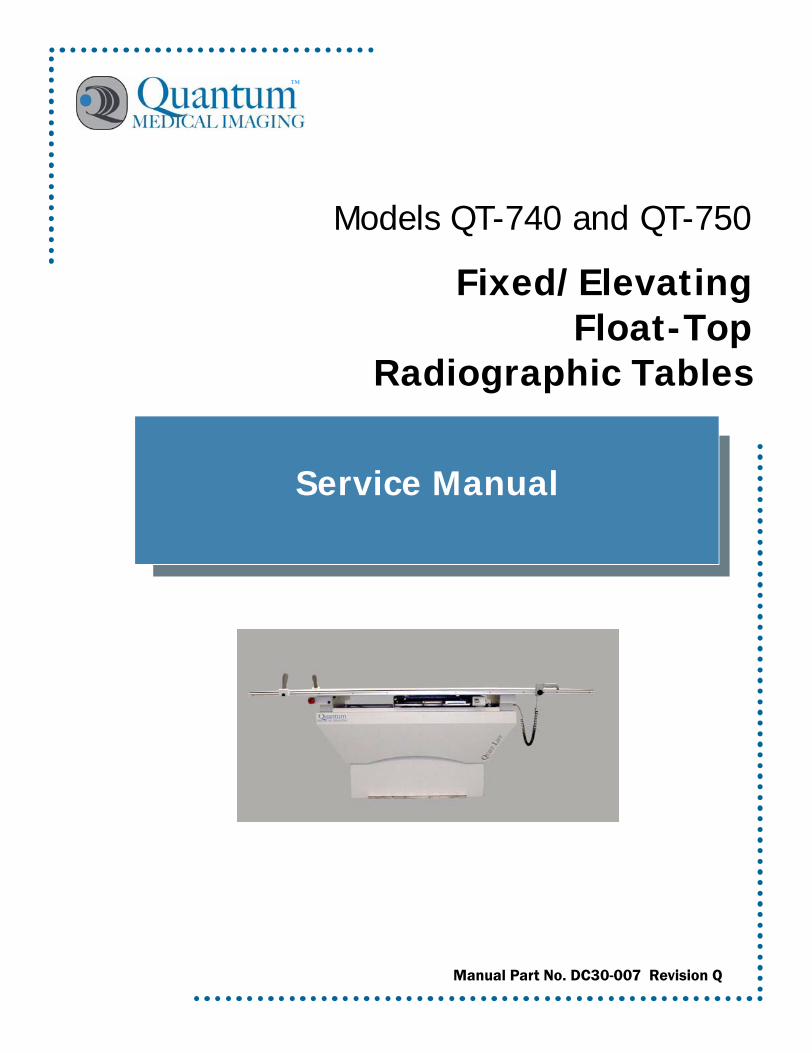
Service Manual
Fixed/ElevatingFloat-Top
Radiographic Tables
™
Models QT-740 and QT-750
Manual Part No. DC30-007 Revision Q

EU Authorized Representative:Medizintechnik Berlin GmbHAltentreptower, Strasse 5912683 Berlin - Germany
Phone: +49-302-82 4726Fax: +49-302-82 6382
E-mail: [email protected]
This manual is copyrighted and all rights are reserved. No portion of this document may be copied, photocopied, reproduced, translated, or reduced to any electronic medium or machine readable form without prior consent in writing from Quantum Medical Imaging, (QMI)
Copyright© 2007 QMI
Made in U.S.A.Quantum Medical Imaging, 2002-B Orville Drive NorthRonkonkoma, New York 11779 USAPhone: (631) 567-5800Fax: (631) 567-5074E-mail: [email protected]
THE ORIGINAL VERSION OF THIS MANUAL DATED DECEMBER 7, 2000 HAS BEEN DRAFTED IN THE ENGLISH LANGUAGE BY QUANTUM MEDICAL IMAGING
Models QT-740 & QT-750 - Service Manual Revision QQuantum Medical Imaging i
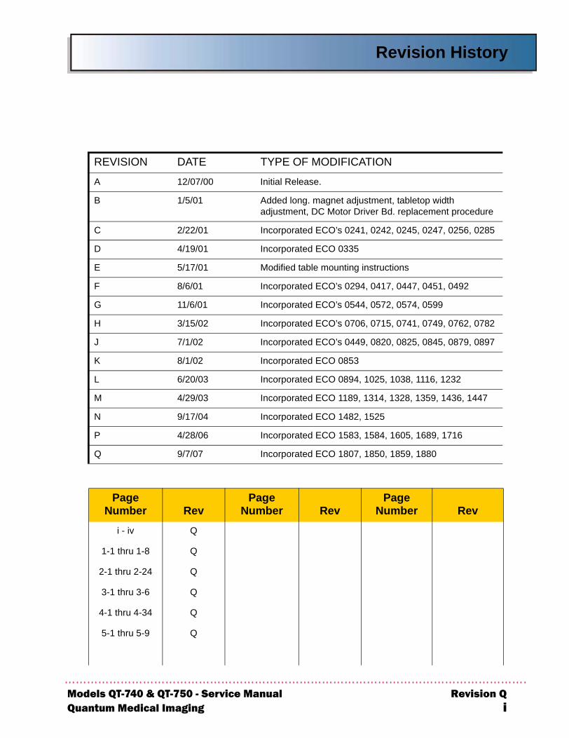
Revision History
REVISION DATE TYPE OF MODIFICATION
A 12/07/00 Initial Release.
B 1/5/01 Added long. magnet adjustment, tabletop width adjustment, DC Motor Driver Bd. replacement procedure
C 2/22/01 Incorporated ECO’s 0241, 0242, 0245, 0247, 0256, 0285
D 4/19/01 Incorporated ECO 0335
E 5/17/01 Modified table mounting instructions
F 8/6/01 Incorporated ECO’s 0294, 0417, 0447, 0451, 0492
G 11/6/01 Incorporated ECO’s 0544, 0572, 0574, 0599
H 3/15/02 Incorporated ECO’s 0706, 0715, 0741, 0749, 0762, 0782
J 7/1/02 Incorporated ECO’s 0449, 0820, 0825, 0845, 0879, 0897
K 8/1/02 Incorporated ECO 0853
L 6/20/03 Incorporated ECO 0894, 1025, 1038, 1116, 1232
M 4/29/03 Incorporated ECO 1189, 1314, 1328, 1359, 1436, 1447
N 9/17/04 Incorporated ECO 1482, 1525
P 4/28/06 Incorporated ECO 1583, 1584, 1605, 1689, 1716
Q 9/7/07 Incorporated ECO 1807, 1850, 1859, 1880
PageNumber Rev
PageNumber Rev
PageNumber Rev
i - iv Q
1-1 thru 1-8 Q
2-1 thru 2-24 Q
3-1 thru 3-6 Q
4-1 thru 4-34 Q
5-1 thru 5-9 Q

Revision Q Models QT-740 & QT-750 - Service Manualii Quantum Medical Imaging
Revision History
THIS PAGE INTENTIONALLY LEFT BLANK

Table of Contents
Models QQuantum
Chapter 1 Specifications
PHYSICAL SPECIFICATIONS ................................................................................. 1-3TABLETOP SPECIFICATIONS ............................................................................. 1-3
TABLE BASE SPECIFICATIONS ........................................................................... 1-3
IMAGE RECEPTOR SPECIFICATIONS .................................................................. 1-3
SYSTEM SPECIFICATIONS ................................................................................. 1-4
ELECTRICAL SPECIFICATIONS .............................................................................. 1-4SYSTEM OPTIONS ................................................................................................ 1-4SYSTEM OPERATING ENVIRONMENT .................................................................... 1-4NON-OPERATING ENVIRONMENT ......................................................................... 1-4
Chapter 2 Assembly & Installation
OVERVIEW .......................................................................................................... 2-3UNPACKING ........................................................................................................ 2-3TABLE ASSEMBLY ................................................................................................ 2-3
POSITIONING THE TABLE BASE ........................................................................ 2-3
ELECTRICAL CONNECTIONS .............................................................................. 2-4
Power Input Connections (Power Cord with Plug Configuration) .................... 2-4
Power Input Connections (Permanent Wiring Configuration) ......................... 2-4
Re-Configuring AC Line Input Transformer (115 VAC/230 VAC Input) ............ 2-6
Bucky Power Input Connections .................................................................. 2-6
PBL Interlock Cable Connections ................................................................. 2-6
TABLE LEVELING AND MOUNTING ........................................................................ 2-8MODEL QT-740 - LEVELING AND MOUNTING INSTRUCTIONS ............................. 2-8
MODEL QT-750 - LEVELING AND MOUNTING INSTRUCTIONS ............................. 2-8
ALIGNMENT PROCEDURES ................................................................................... 2-9IMAGE RECEPTOR/COLLIMATOR X-RAY ALIGNMENT .......................................... 2-9
TABLETOP ASSEMBLY/INSTALLATION ............................................................. 2-11
REDUCING THE TABLE TOP HEIGHT (MODEL QT-750 ONLY) ............................ 2-14
OPERATOR CONTROL HANDLE ASSEMBLY INSTALLATION ................................ 2-16
OPERATIONAL CHECKS AND ADJUSTMENTS ........................................................ 2-17CHECKING TABLE FLOAT-TOP OPERATION ...................................................... 2-17
CHECKING UP/DOWN OPERATION (MODEL QT-750 ONLY) ............................... 2-17
TABLE UP/DOWN SPEED ADJUSTMENT (MODEL QT-750 ONLY) ........................ 2-18
PEDAL DISABLE SWITCH OPERATIONAL CHECK ............................................... 2-18
CHECKING THE OBSTRUCTION SENSORS (ELEVATING TABLE ONLY) ................ 2-19
RECEPTOR CABINET LOCKING MAGNET CHECK ............................................... 2-20
POSITIVE BEAM LIMITATION (PBL) COLLIMATORS .......................................... 2-21
MODEL QT-750 COVERS INSTALLATION/ADJUSTMENT PROCEDURE ..................... 2-21MODEL QT-740 COVERS INSTALLATION PROCEDURE .......................................... 2-23
T-740 & QT-750 - Service Manual Revision QMedical Imaging iii
Table of Contents
Riv
Chapter 3 Theory of OperationOVERVIEW ..........................................................................................................3-3
MODEL QT-740 TABLE ......................................................................................3-3
Power Distribution ......................................................................................3-3
Float Control ..............................................................................................3-4
Foot Pedal Disable Circuit ...........................................................................3-4
Receptor Cabinet Lock ................................................................................3-4
MODEL QT-750 TABLE ......................................................................................3-4
Power Distribution ......................................................................................3-4
Voltage Regulation .....................................................................................3-5
Float Control ..............................................................................................3-5
Foot Pedal Disable Switch ...........................................................................3-5
Positive Beam Limitation .............................................................................3-5
Receptor Cabinet Lock ................................................................................3-5
Emergency Stop Switch ..............................................................................3-5
Chapter 4 Service InstructionsOVERVIEW ..........................................................................................................4-3
SERVICE MAINTENANCE ...................................................................................4-4
Visual Inspection ........................................................................................4-4
Functional Check for Model QT-750 Elevating Tables ....................................4-4
Lubrication ................................................................................................4-5
Float Top Locking Magnet Check .................................................................4-6
TROUBLESHOOTING PROCEDURES ....................................................................4-8
REMOVAL/REPLACEMENT PROCEDURES ...........................................................4-13
Replacing the Drive Belt (Model QT-750 Tables Only) .................................4-13
Replacing the Sync Belt (Model QT-750 Tables Only) ..................................4-14
Replacing the DC Motor (Model QT-750 Tables Only) ..................................4-16
Replacing the DC Motor Driver Board A2 (Model QT-750 Tables Only) ..........4-18
Receptor Cabinet Removal/Replacement ....................................................4-22
Cassette Tray Removal Procedure .............................................................4-23
REPLACEMENT PARTS AND ORDERING INFORMATION .....................................4-24
ORDERING INFORMATION ..............................................................................4-27
Chapter 5 DiagramsModel QT-740 Radiographic Table Wiring Diagram ..............................................5-3
Model QT-750 Radiographic Table Wiring Diagram ..............................................5-4
4-Way Table Control Board A1 (AY40-017T) .......................................................5-5
6-Way Table Control Board A1 (AY40-030T) Test Point Diagram ..........................5-6
Table Base Plate Mounting Hole Locations ..........................................................5-7
Installing Digital Image Receptor Using QT-FCD Mounting Bracket .......................5-8
Installing Digital Image Receptor Using QT-DDS Slide Mounting Bracket ...............5-9
evision Q Models QT-740 & QT-750 - Service ManualQuantum Medical Imaging

Chapter
1-1
SPECIFICATIONS
1

1-2
Chapter 1 Specifications
Models QT-7Quantum M
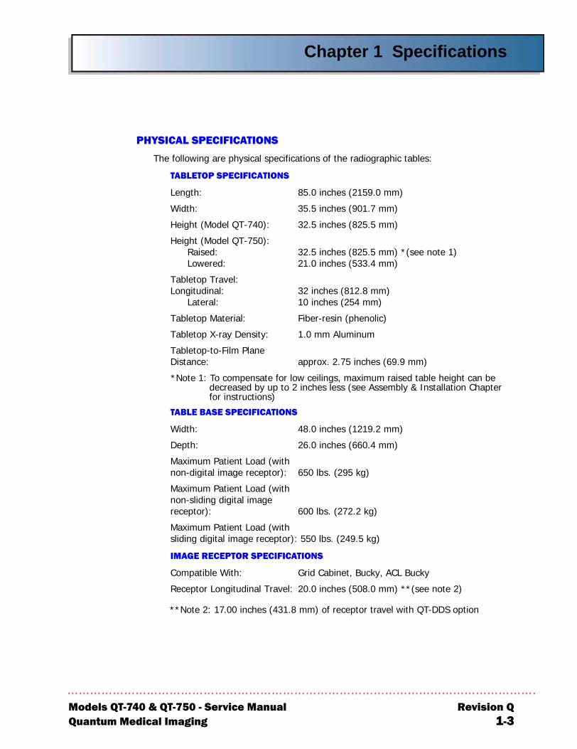
PHYSICAL SPECIFICATIONS
The following are physical specifications of the radiographic tables:
TABLETOP SPECIFICATIONS
Length: 85.0 inches (2159.0 mm)
Width: 35.5 inches (901.7 mm)
Height (Model QT-740): 32.5 inches (825.5 mm)
Height (Model QT-750):Raised: 32.5 inches (825.5 mm) *(see note 1)Lowered: 21.0 inches (533.4 mm)
Tabletop Travel:Longitudinal: 32 inches (812.8 mm)
Lateral: 10 inches (254 mm)
Tabletop Material: Fiber-resin (phenolic)
Tabletop X-ray Density: 1.0 mm Aluminum
Tabletop-to-Film Plane Distance: approx. 2.75 inches (69.9 mm)
*Note 1: To compensate for low ceilings, maximum raised table height can be decreased by up to 2 inches less (see Assembly & Installation Chapter for instructions)
TABLE BASE SPECIFICATIONS
Width: 48.0 inches (1219.2 mm)
Depth: 26.0 inches (660.4 mm)
Maximum Patient Load (with non-digital image receptor): 650 lbs. (295 kg)
Maximum Patient Load (with non-sliding digital image receptor): 600 lbs. (272.2 kg)
Maximum Patient Load (with sliding digital image receptor): 550 lbs. (249.5 kg)
IMAGE RECEPTOR SPECIFICATIONS
Compatible With: Grid Cabinet, Bucky, ACL Bucky
Receptor Longitudinal Travel: 20.0 inches (508.0 mm) **(see note 2)
**Note 2: 17.00 inches (431.8 mm) of receptor travel with QT-DDS option
40 & QT-750 - Service Manual Revision Qedical Imaging 1-3
Chapter 1 Specifications
R1
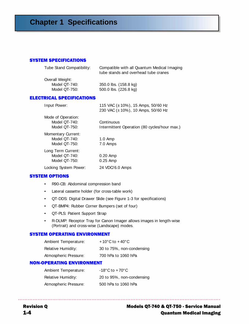
SYSTEM SPECIFICATIONSTube Stand Compatibility: Compatible with all Quantum Medical Imaging
tube stands and overhead tube cranes
Overall Weight:Model QT-740: 350.0 lbs. (158.8 kg)Model QT-750: 500.0 lbs. (226.8 kg)
ELECTRICAL SPECIFICATIONSInput Power: 115 VAC (±10%), 15 Amps, 50/60 Hz
230 VAC (±10%), 10 Amps, 50/60 Hz
Mode of Operation:Model QT-740: ContinuousModel QT-750: Intermittent Operation (80 cycles/hour max.)
Momentary Current:Model QT-740: 1.0 AmpModel QT-750: 7.0 Amps
Long Term Current:Model QT-740: 0.20 AmpModel QT-750: 0.25 Amp
Locking System Power: 24 VDC/6.0 Amps
SYSTEM OPTIONS
• R90-CB: Abdominal compression band
• Lateral cassette holder (for cross-table work)
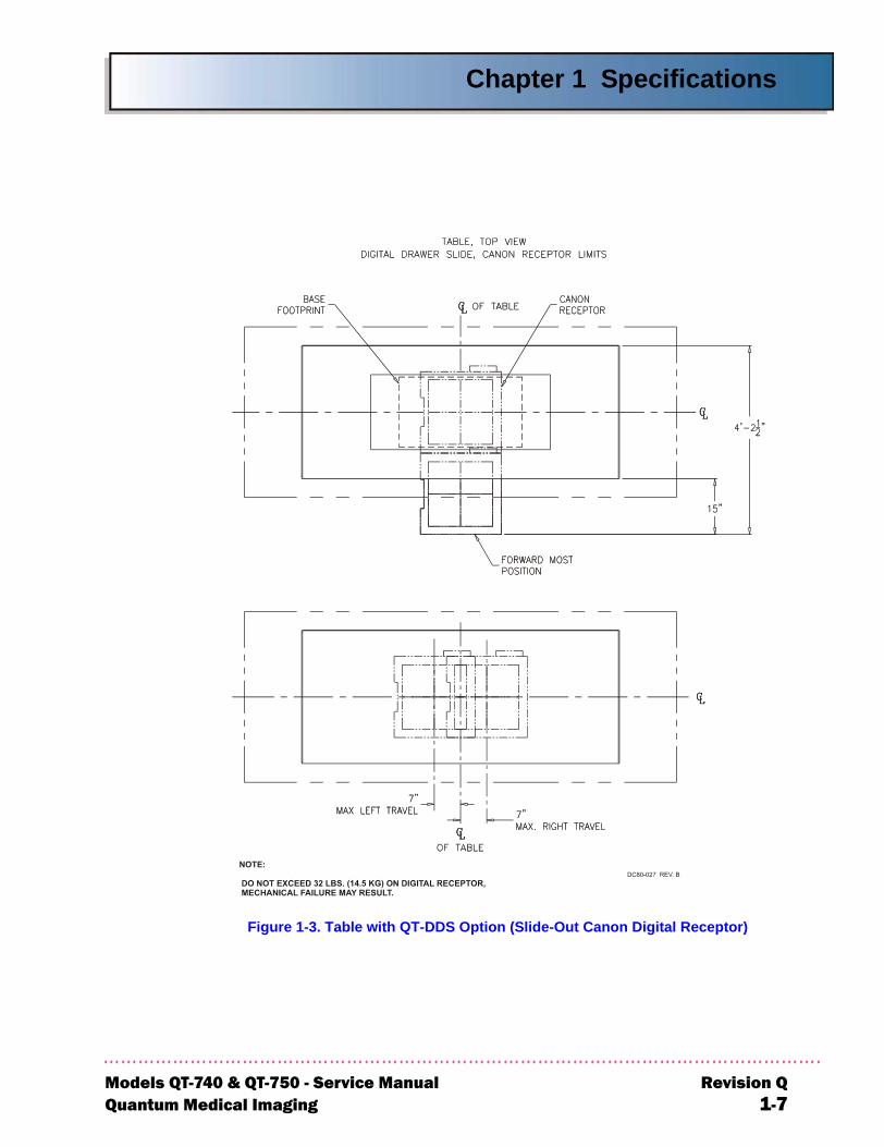
• QT-DDS: Digital Drawer Slide (see Figure 1-3 for specifications)
• QT-BMP4: Rubber Corner Bumpers (set of four)
• QT-PLS: Patient Support Strap
• R-DLMP: Receptor Tray for Canon Imager allows images in length-wise (Portrait) and cross-wise (Landscape) modes.
SYSTEM OPERATING ENVIRONMENTAmbient Temperature: +10°C to +40°C
Relative Humidity: 30 to 75%, non-condensing
Atmospheric Pressure: 700 hPa to 1060 hPa
NON-OPERATING ENVIRONMENTAmbient Temperature: -18°C to +70°C
Relative Humidity: 20 to 95%, non-condensing
Atmospheric Pressure: 500 hPa to 1060 hPa
evision Q Models QT-740 & QT-750 - Service Manual-4 Quantum Medical Imaging
Chapter 1 Specifications
Models QT-7Quantum M
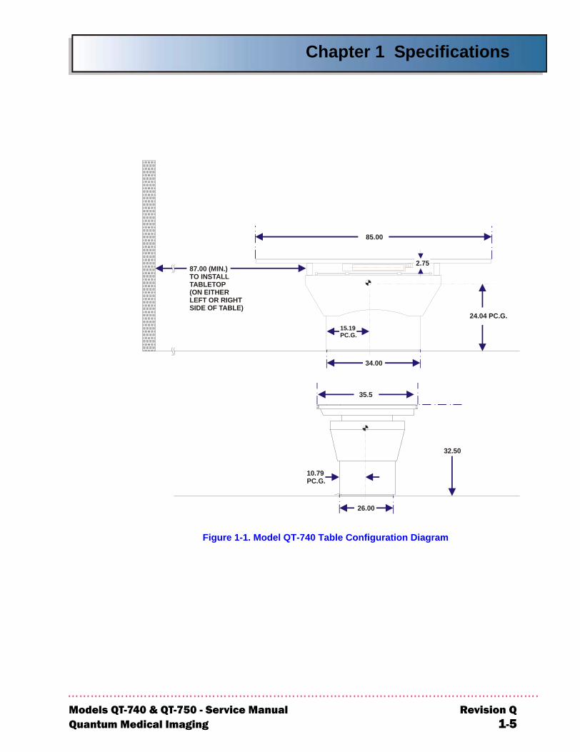
Figure 1-1. Model QT-740 Table Configuration Diagram
85.00
87.00 (MIN.)TO INSTALLTABLETOP(ON EITHERLEFT OR RIGHTSIDE OF TABLE)
35.5
34.00
26.00
10.79PC.G.
32.50
2.75
24.04 PC.G.15.19PC.G.
40 & QT-750 - Service Manual Revision Qedical Imaging 1-5
Chapter 1 Specifications
R1
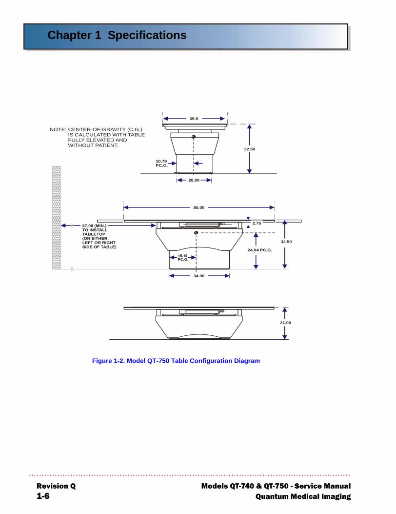
Figure 1-2. Model QT-750 Table Configuration Diagram
85.00
34.00
32.50
21.00
2.75
NOTE: CENTER-OF-GRAVITY (C.G.) IS CALCULATED WITH TABLE FULLY ELEVATED AND WITHOUT PATIENT.
24.04 PC.G.
35.5
26.00
10.79PC.G.
32.50
evision Q Models QT-740 & QT-750 - Service Manual-6 Quantum Medical Imaging
Chapter 1 Specifications
Models QT-7Quantum M
Figure 1-3. Table with QT-DDS Option (Slide-Out Canon Digital Receptor)
40 & QT-750 - Service Manual Revision Qedical Imaging 1-7

Chapter 1 Specifications
R1
THIS PAGE INTENTIONALLY LEFT BLANK
evision Q Models QT-740 & QT-750 - Service Manual-8 Quantum Medical Imaging

Chapter
2-1
ASSEMBLY &INSTALLATION
2

2-2
Chapter 2 Assembly & Installation
Models QTQuantum
NOTE
Examine all car-tons and crates carefully at time of delivery. If damage is appar-ent, have deliv-ery driver write a "Damaged Ship-ment Note" on copies of freight bill, sign it, and file appropriate carrier claim. Should you dis-cover concealed damage, immedi-ately notify the transporting agent and ask for an "Inspection of Damage". Carrier will not accept concealed dam-age claim if filed after 15 days from date of receipt of mer-chandise.
OVERVIEW
Preparing the table for operation requires completion of the following tasks:
• Positioning the Table Base
• Making the Electrical Connections
• Alignment Procedures
• Tabletop Assembly/Installation
• Checking Table Operation
• Installing the Covers
UNPACKING
Open crate or carton marked "packing list enclosed" first. Remove packing list and use it as a guide to open the remaining cartons. Do not dispose of packing material until packing list is matched with actual parts received. Should there be a shortage or damage, notify manufacturer’s customer service department immediately. The manu-facturer is relieved of any responsibility for damage during shipment after unit is picked up by the carrier.
TABLE ASSEMBLY
The radiographic table is shipped with most of its major components assembled. However, the tabletop assembly must be attached to the base assembly and the cov-ers must be installed. After the table is assembled, an operational check is per-formed. (This check is required only on Model QT-750 radiographic tables.)
On systems equipped with QT-FCD option (fixed mount for Canon Digital Image Receptor), refer to Figure 5-5 in Chapter 5, Diagrams for instructions on installing the digital image receptor in the table.
On systems equipped with QT-DDS option (drawer slide mount for Canon Digital Image Receptor), refer to Figure 5-6 in Chapter 5, Diagrams for instructions on installing the digital image receptor in the table.
POSITIONING THE TABLE BASE
Place the table base in the approximate location where it will be mounted. Ensure that the floor below the table is level. When positioning the table base, ensure there is a minimum clearance of 87 inches from the outer edge of Bearing Rail to the wall on either side of the table (see Figures 1-1 and 1-2). This allows for installation of the tabletop rails following table mounting. If enough clearance is provided, proceed to the "Electrical Connections" paragraph in this chapter.
If there is not enough clearance on either side to install the tabletop after the table is mounted to the floor, the tabletop must be installed prior to mounting the table. To install the tabletop, proceed to the paragraph entitled "Tabletop Assem-bly/Installation" before performing the next procedure.
-740 & QT-750 - Service Manual Revision QMedical Imaging 2-3
Chapter 2 Assembly & Installation
R2
ELECTRICAL CONNECTIONS
CAUTION! This equipment contains electrostaticsensitive devices. Observe proper grounding pre-cautions before handling components or printedcircuit boards.
Power Input Connections (Power Cord with Plug Configuration)
For 115 VAC installations, a 25-foot power cord with a hospital-grade plug is factory pre-wired to the table. For 230 VAC installations, a 25-foot "HAR" power cord is factory pre-wired to the table; the installer must attach the proper plug depending on receptacle type used at installation site. If a line cord with plug is provided by the facility, it must have a 16 AWG minimum cord (Type SJT or equivalent) and a hospital grade plug. Connect plug to hospital grade receptacle only. The power supply line input connection is fused internal to the table (2A for 115 VAC line input, 1A for 230 VAC line input for Model QT-740 tables; 6A for 115 VAC line input, 3A for 230 VAC line input for Model QT-750 tables).
Power Input Connections (Permanent Wiring Configuration)
CAUTION! When AC power source is single-phase(e.g., US 115 V and European 230 V), do not fusethe neutral leg if permanently installed. Replaceneutral wire Fuse F1 with dummy fuse, suppliedwith table. When two-phase AC power is used(e.g., US 240 V), both lines must be fused. For fusecharts see Chapter 5 Diagrams, Figure 5-1 forQT-740 Table and Figure 5-2 for QT-750 Table.
The table can be powered from independently fused power source (mains) or from specified equipment, such as an X-ray generator. All electrical connections must be made by a qualified electrician in compli-ance with NEC or local code requirements. Refer to QT-740 or QT-750 Interconnection Diagram in Chapter 5, Diagrams and proceed as follows:
1. To connect external wires to table, either bring cables through the Rear Bottom Cover access opening or, if conduit and flush floor box is run beneath the table, through the large 6" x 5" opening in the table base.
evision Q Models QT-740 & QT-750 - Service Manual-4 Quantum Medical Imaging
Chapter 2 Assembly & Installation
Models QTQuantum
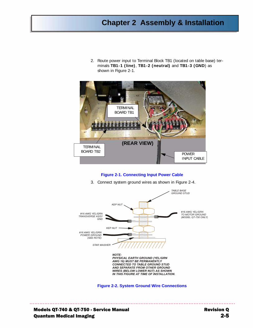
2. Route power input to Terminal Block TB1 (located on table base) ter-minals TB1-1 (line), TB1-2 (neutral) and TB1-3 (GND) as shown in Figure 2-1.
Figure 2-1. Connecting Input Power Cable
3. Connect system ground wires as shown in Figure 2-4.
Figure 2-2. System Ground Wire Connections
TERMINALBOARD TB2
TERMINALBOARD TB1
(REAR VIEW)
POWER INPUT CABLE
-740 & QT-750 - Service Manual Revision QMedical Imaging 2-5
Chapter 2 Assembly & Installation
R2
Re-Configuring AC Line Input Transformer (115 VAC/230 VAC Input)
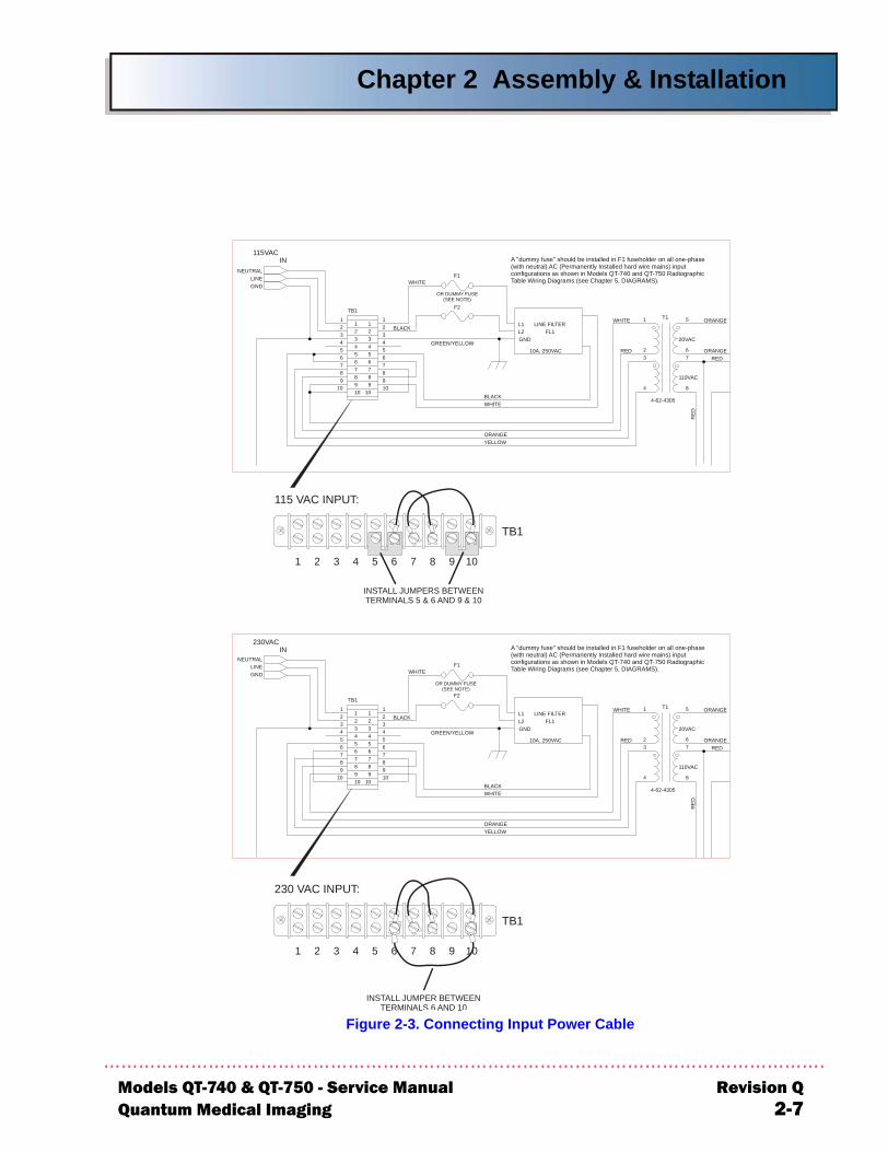
Typically, the AC line input transformer is configured at factory in accor-dance with user facility electrical requirements (i.e., 115 VAC or 230 VAC). If it is necessary to re-configure from 115 VAC to 230 VAC, or 230 VAC to 115 VAC, make connections at terminal block TB1, located on table base, as shown in Figure 2-3 and Model QT-740 and QT-750 Radio-graphic Table Wiring Diagrams in Chapter 5, Diagrams.
In addition, on Model QT-740 tables:
• For 115 VAC line input, the rating of fuse F2 and F1 should be 2 Amps, 250V slow-blow (see FFigureigure 5-1, Chapter 5, Diagrams for fuse applications chart.)
• For 230 VAC line input Model QT-750 tables, the rating of fuse F2 and F1 should be 1 Amp, 250V slow-blow
On Model QT-750 tables:
• For 115 VAC line input, the rating of fuse F2 (and F1 if two-phase AC input) should be 6 Amps, 250V slow-blow
• For 230 VAC line input Model QT-750 tables, the rating of fuse F2 and F1 should be 3 Amps, 250V slow-blow(see Figure 5-2, Chapter 5, Diagrams for fuse applications chart.)
CAUTION! A "dummy fuse" should be installed inF1 fuseholder on all one-phase (with neutral) AC(Permanently Installed hard wire mains) inputconfigurations as shown in Models QT-740 andQT-750 Radiographic Table Wiring Diagrams (seeChapter 5, DIAGRAMS).
Bucky Power Input Connections
To connect bucky wiring to table, route bucky cable through rear bottom cover access opening to Terminal Block TB2 (see Figure 2-1). Refer to Q-740 and QT-750 Table Wiring Diagrams in Chapter 5, Diagrams and to bucky manufacturer’s installation manual (provided with system) for spe-cific bucky wiring information.
PBL Interlock Cable Connections
On Model QT-750 tables using PBL interlock, connect PBL cable in accor-dance with QT-740 and QT-750 Table Wiring Diagrams (refer to Chapter 5, Diagrams).
evision Q Models QT-740 & QT-750 - Service Manual-6 Quantum Medical Imaging
Chapter 2 Assembly & Installation
Models QTQuantum M
T1
4-62-4305
4
1
23
8
76
5
F1
OR DUMMY FUSE(SEE NOTE)
F2TB1
77
66 55 44 33
22 11
77
66554433
2211
88
88
99
10109
9
1010
NEUTRAL
GNDLINE
GND
L1
IN
LINE FILTER
115VAC
FL120VAC
10A, 250VAC
L2
110VAC
BLACK
WHITE
BLACKWHITE
GREEN/YELLOW
WHITE
RED
ORANGEYELLOW
ORANGE
ORANGERED
RED
INSTALL JUMPERS BETWEENTERMINALS 5 & 6 AND 9 & 10
115 VAC INPUT:
TB1
1 2 3 4 5 6 7 8 9 10
T1
4-62-4305
4
1
23
8
76
5
F1
A "dummy fuse" should be installed in F1 fuseholder on all one-phase(with neutral) AC (Permanently Installed hard wire mains) inputconfigurations as shown in Models QT-740 and QT-750 RadiographicTable Wiring Diagrams (see Chapter 5, DIAGRAMS).
F2TB1
77
66
55 44 33 22 11
77
66
55443322
11
88
88
99
10109
9
1010
GND
L1
IN
LINE FILTER
230VAC
FL120VAC
10A, 250VAC
L2
110VAC
BLACK
WHITE
BLACKWHITE
GREEN/YELLOW
WHITE
RED
ORANGEYELLOW
ORANGE
ORANGERED
RE
D
INSTALL JUMPER BETWEENTERMINALS 6 AND 10
230 VAC INPUT:
TB1
1 2 3 4 5 6 7 8 9 10
NEUTRAL
GNDLINE
OR DUMMY FUSE(SEE NOTE)
A "dummy fuse" should be installed in F1 fuseholder on all one-phase(with neutral) AC (Permanently Installed hard wire mains) inputconfigurations as shown in Models QT-740 and QT-750 RadiographicTable Wiring Diagrams (see Chapter 5, DIAGRAMS).
Figure 2-3. Connecting Input Power Cable
-740 & QT-750 - Service Manual Revision Qedical Imaging 2-7

Chapter 2 Assembly & Installation
R2
TABLE LEVELING AND MOUNTING
The following paragraphs describe the steps necessary to level and mount ModelsQT-740 and QT-750 tables.
MODEL QT-740 - LEVELING AND MOUNTING INSTRUCTIONS
1. Move the QT-740 table into position according to room plan.
2. Place protective covering over boards and components located on the table base plate to prevent damage from dust and debris during drilling.
3. Using the six (6) table Base Plate 3/8" diameter mounting holes as a guide, transfer drill through the table base plate mounting holes.
4. Place a level on the table or bucky. A double-bubble level at least 18" long is recommended. If the table is not perfectly level, place the flat shim plates near the mounting locations (below the 1/2" aluminum base plate) as required until the table or bucky reads level. The shims, which measure approximately 3" x 5", are included with the table hardware kit.
5. Mount table to floor using hardware suitable for the type of floor in the instal-lation and of sufficient strength to handle 500 lb. pull-load.
MODEL QT-750 - LEVELING AND MOUNTING INSTRUCTIONS
1. Figure 5-5 in Chapter 5, DIAGRAMS shows the locations of the table mount-ing holes and cable through openings. Using Figure 5-5 as a guide, mark locations of the six (6) 3/8" diameter Base Plate mounting holes on the floor.
2. Drill the six (6) mounting holes as marked on floor.
3. Place Base Plate Sound-Proof Material (P/N ME30-081) into position over drilled holes.
4. Move table into position on top of Base Plate Sound-Proof Material.
5. Place a level on the table or bucky. A double-bubble level at least 18" long is recommended.
6. If the table is not perfectly level, place the flat shim plates near the mounting locations as required until the table or bucky reads level.
7. Mount table to floor using hardware suitable for the type of floor in the instal-lation and of sufficient strength to handle 500 lb. pull-load.
evision Q Models QT-740 & QT-750 - Service Manual-8 Quantum Medical Imaging

Chapter 2 Assembly & Installation
Models QTQuantum
ALIGNMENT PROCEDURES
IMAGE RECEPTOR/COLLIMATOR X-RAY ALIGNMENT
The image receptor must be properly aligned with the projected light field of the collimator in order to provide accurate x-ray exposures. If the tube stand used with the table provides transverse travel of the x-ray tube relative to the table, set the tube transverse travel in the center detent position prior to performing align-ment.
The following x-ray alignment procedure may require slight repositioning of the table base. This movement may affect the position or arrangement of the leveling plates, requiring an additional check that the table remains level.
Collimator calibration, tube stand alignments, and collimator light field to x-ray field adjustments, as described in their respective manuals, must be performed prior to the following procedure.
1. If the tabletop is installed, remove the radiographic portion of the tabletop, otherwise, proceed to step 2. The tabletop is held on with dual-lock tape; lift up a corner then carefully pull the tabletop off.
2. With the collimator parallel to the tabletop (0°), turn on the collimator light. Using the light field adjusting knobs on the collimator, reduce the light field to a narrow beam of light along the length of the table.
3. Position the collimator to approximately 24" source-to-image distance (SID).
4. Insert a 14" x 17" cassette into the film tray.
5. Turn on power to the table.
6. Turn on the collimator light and, if necessary, loosen mounting hardware and move the entire table so that the longitudinal center line on the cassette (i.e., the line which is parallel to the length of the table) is properly aligned with the narrow beam of light (see Figure 2-4).
-740 & QT-750 - Service Manual Revision QMedical Imaging 2-9
Chapter 2 Assembly & Installation
R2
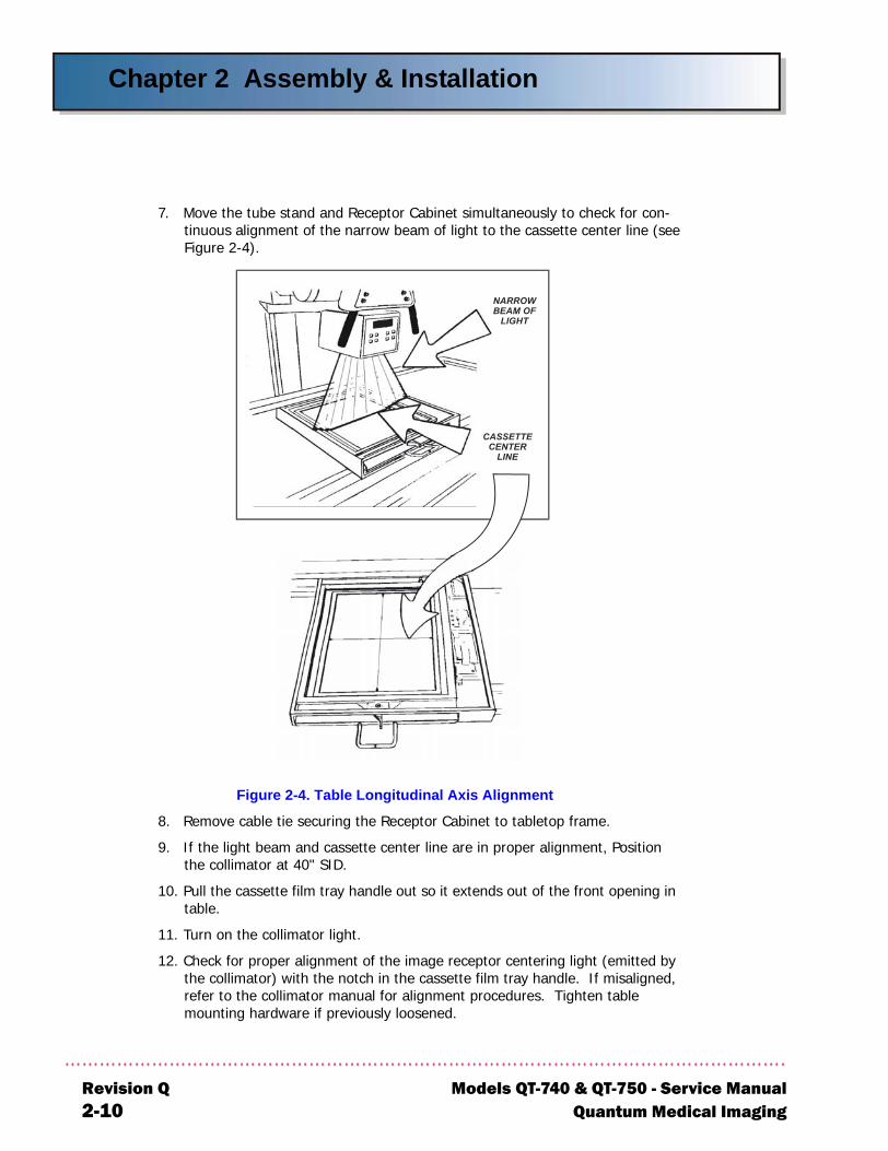
7. Move the tube stand and Receptor Cabinet simultaneously to check for con-tinuous alignment of the narrow beam of light to the cassette center line (seeFigure 2-4).
Figure 2-4. Table Longitudinal Axis Alignment
8. Remove cable tie securing the Receptor Cabinet to tabletop frame.
9. If the light beam and cassette center line are in proper alignment, Position the collimator at 40" SID.
10. Pull the cassette film tray handle out so it extends out of the front opening in table.
11. Turn on the collimator light.
12. Check for proper alignment of the image receptor centering light (emitted by the collimator) with the notch in the cassette film tray handle. If misaligned, refer to the collimator manual for alignment procedures. Tighten table mounting hardware if previously loosened.
evision Q Models QT-740 & QT-750 - Service Manual-10 Quantum Medical Imaging
Chapter 2 Assembly & Installation
Models QTQuantum M
TABLETOP ASSEMBLY/INSTALLATION
CAUTION! Be careful not to damage the Obstruc-tion Sensors when installing the Tabletop Assem-bly.
The following procedure describes how to install the Tabletop Assembly in the Tabletop Frame.
1. Unpack the Tabletop Assembly from the carton.
2. At the left end of the Tabletop Assembly (as viewed from front of table), remove three (3) 1/4-20 x 1" low profile socket head screws securing End Trim Plate to Tabletop End Support. Note: The front edge of table top is indi-cated by a label.
IMPORTANT! All shims located between theTabletop End Support and Rear Table Rail must bere-installed in exactly the same quantity and loca-tion for tabletop to be square. If not, tabletopmotion may be adversely affected.
-740 & QT-750 - Service Manual Revision Qedical Imaging 2-11
Chapter 2 Assembly & Installation
Re2-
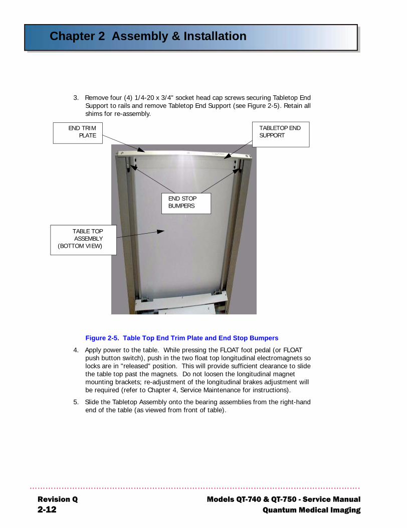
3. Remove four (4) 1/4-20 x 3/4" socket head cap screws securing Tabletop End Support to rails and remove Tabletop End Support (see Figure 2-5). Retain all shims for re-assembly.
Figure 2-5. Table Top End Trim Plate and End Stop Bumpers
4. Apply power to the table. While pressing the FLOAT foot pedal (or FLOAT push button switch), push in the two float top longitudinal electromagnets so locks are in "released" position. This will provide sufficient clearance to slide the table top past the magnets. Do not loosen the longitudinal magnet mounting brackets; re-adjustment of the longitudinal brakes adjustment will be required (refer to Chapter 4, Service Maintenance for instructions).
5. Slide the Tabletop Assembly onto the bearing assemblies from the right-hand end of the table (as viewed from front of table).
END STOP BUMPERS
END TRIMPLATE
TABLETOP END SUPPORT
TABLE TOPASSEMBLY
(BOTTOM VIEW)
vision Q Models QT-740 & QT-750 - Service Manual12 Quantum Medical Imaging
Chapter 2 Assembly & Installation
Models QTQuantum M
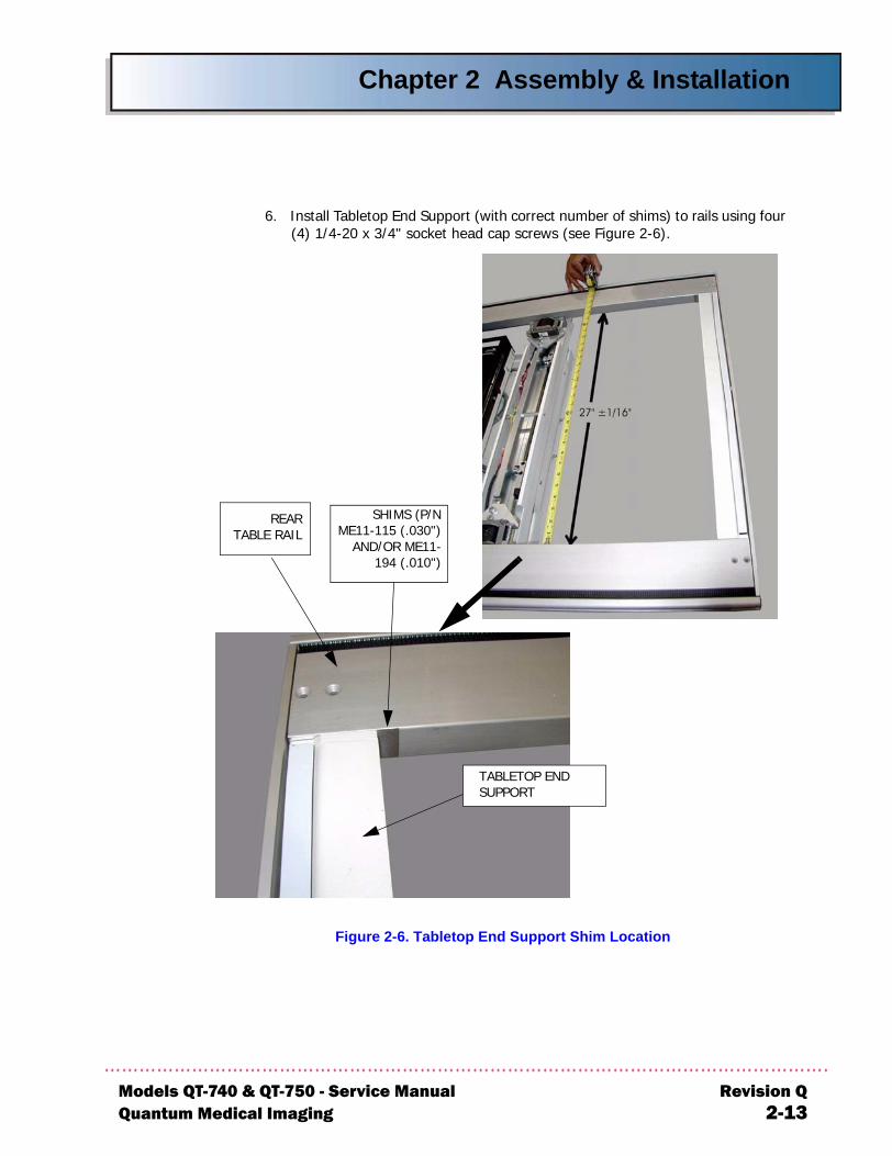
6. Install Tabletop End Support (with correct number of shims) to rails using four (4) 1/4-20 x 3/4" socket head cap screws (see Figure 2-6).
Figure 2-6. Tabletop End Support Shim Location
SHIMS (P/NME11-115 (.030")
AND/OR ME11-194 (.010")
TABLETOP END SUPPORT
REARTABLE RAIL
-740 & QT-750 - Service Manual Revision Qedical Imaging 2-13
Chapter 2 Assembly & Installation
Re2-
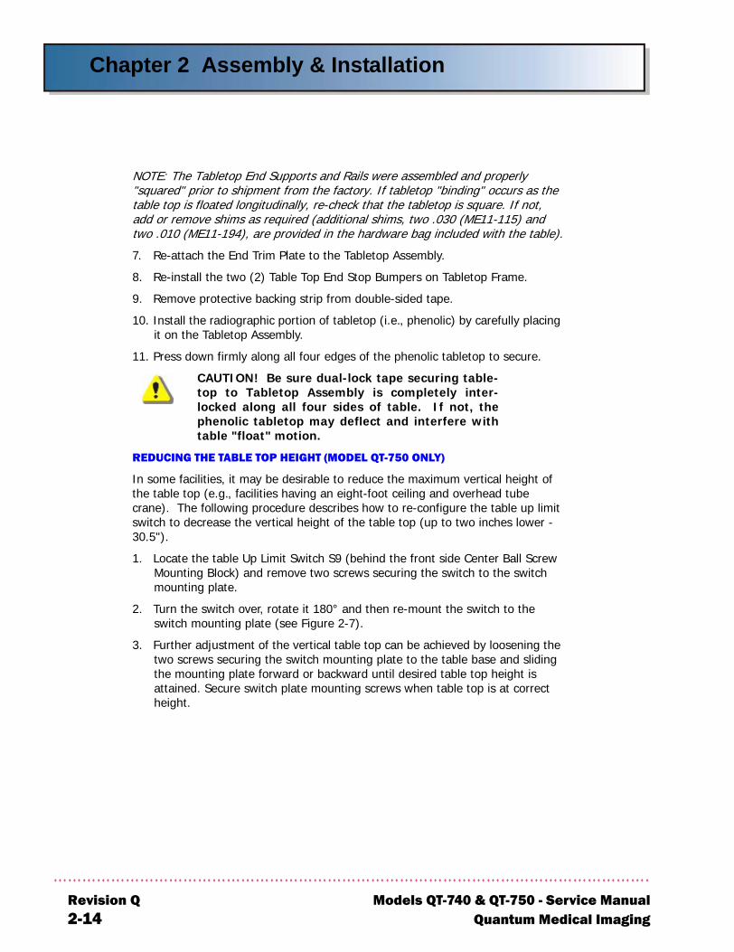
NOTE: The Tabletop End Supports and Rails were assembled and properly "squared" prior to shipment from the factory. If tabletop "binding" occurs as the table top is floated longitudinally, re-check that the tabletop is square. If not, add or remove shims as required (additional shims, two .030 (ME11-115) and two .010 (ME11-194), are provided in the hardware bag included with the table).
7. Re-attach the End Trim Plate to the Tabletop Assembly.
8. Re-install the two (2) Table Top End Stop Bumpers on Tabletop Frame.
9. Remove protective backing strip from double-sided tape.
10. Install the radiographic portion of tabletop (i.e., phenolic) by carefully placing it on the Tabletop Assembly.
11. Press down firmly along all four edges of the phenolic tabletop to secure.
CAUTION! Be sure dual-lock tape securing table-top to Tabletop Assembly is completely inter-locked along all four sides of table. If not, thephenolic tabletop may deflect and interfere withtable "float" motion.
REDUCING THE TABLE TOP HEIGHT (MODEL QT-750 ONLY)
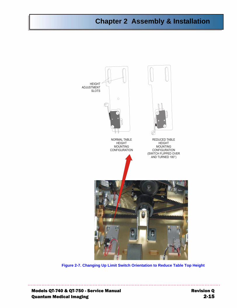
In some facilities, it may be desirable to reduce the maximum vertical height of the table top (e.g., facilities having an eight-foot ceiling and overhead tube crane). The following procedure describes how to re-configure the table up limit switch to decrease the vertical height of the table top (up to two inches lower - 30.5").
1. Locate the table Up Limit Switch S9 (behind the front side Center Ball Screw Mounting Block) and remove two screws securing the switch to the switch mounting plate.
2. Turn the switch over, rotate it 180° and then re-mount the switch to the switch mounting plate (see Figure 2-7).
3. Further adjustment of the vertical table top can be achieved by loosening the two screws securing the switch mounting plate to the table base and sliding the mounting plate forward or backward until desired table top height is attained. Secure switch plate mounting screws when table top is at correct height.
vision Q Models QT-740 & QT-750 - Service Manual14 Quantum Medical Imaging
Chapter 2 Assembly & Installation
Models QTQuantum M
Figure 2-7. Changing Up Limit Switch Orientation to Reduce Table Top Height
-740 & QT-750 - Service Manual Revision Qedical Imaging 2-15
Chapter 2 Assembly & Installation
Re2-
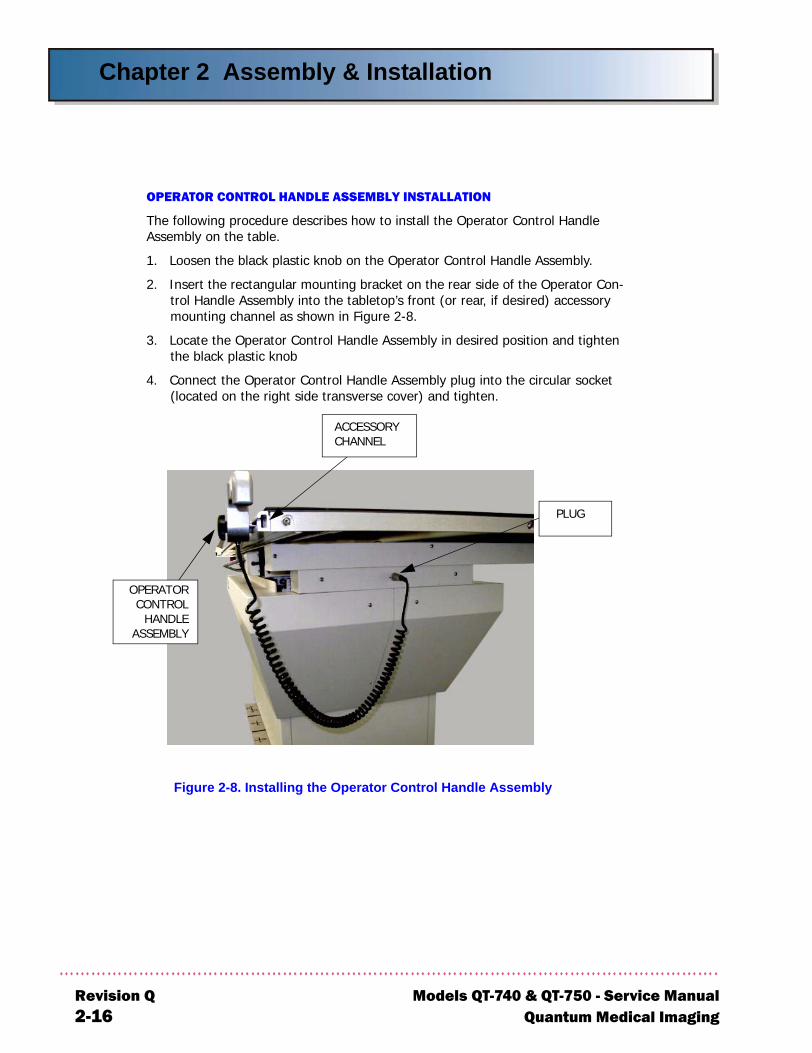
OPERATOR CONTROL HANDLE ASSEMBLY INSTALLATION
The following procedure describes how to install the Operator Control Handle Assembly on the table.
1. Loosen the black plastic knob on the Operator Control Handle Assembly.
2. Insert the rectangular mounting bracket on the rear side of the Operator Con-trol Handle Assembly into the tabletop’s front (or rear, if desired) accessory mounting channel as shown in Figure 2-8.
3. Locate the Operator Control Handle Assembly in desired position and tighten the black plastic knob
4. Connect the Operator Control Handle Assembly plug into the circular socket (located on the right side transverse cover) and tighten.
Figure 2-8. Installing the Operator Control Handle Assembly
PLUG
OPERATORCONTROL
HANDLEASSEMBLY
ACCESSORY CHANNEL
vision Q Models QT-740 & QT-750 - Service Manual16 Quantum Medical Imaging

Chapter 2 Assembly & Installation
Models QTQuantum
NOTEThe DC Motor Driver Board A2 has five (5) trim pots identified on the printed circuit board that are factory calibrated and should not require any further adjustment.
OPERATIONAL CHECKS AND ADJUSTMENTS
When the table is completely assembled and all required electrical connections have been made, perform the following tests to verify proper system operation. Tests for the table’s elevating (up/down) functions and positive beam limitation (PBL) are required only on Model QT-750 tables.
CHECKING TABLE FLOAT-TOP OPERATION
1. Depress the FLOAT foot pedal. The tabletop should move freely in either direction. Release the FLOAT foot pedal. The tabletop should be locked securely in its present position.
2. Depress the FLOAT push button on the Operator Control Handle Assembly. The tabletop should move freely in either direction. Release the FLOAT push button. The tabletop should be locked securely in its present position.
CHECKING UP/DOWN OPERATION (MODEL QT-750 ONLY)
1. Depress the UP and then the DOWN foot pedal. The following should occur while each foot pedal is depressed:
a. The tabletop should start to move up (while the UP foot pedal is pressed) and down (while the DOWN foot pedal is pressed).
b. The FLOAT foot pedal (the outside pedals) should be disabled (i.e., the tabletop should remain locked) while the tabletop is moving up or down.
c. With the table running either up or down, press the red Emergency Stop Switch. Table up or down motion should stop. Turn the Emer-gency Stop Switch counterclockwise until it is released. Tabletop up/down motion is now enabled when foot pedals are pressed.
2. Repeat previous step using the Operator Control Handle Assembly Up/Down rocker switch.
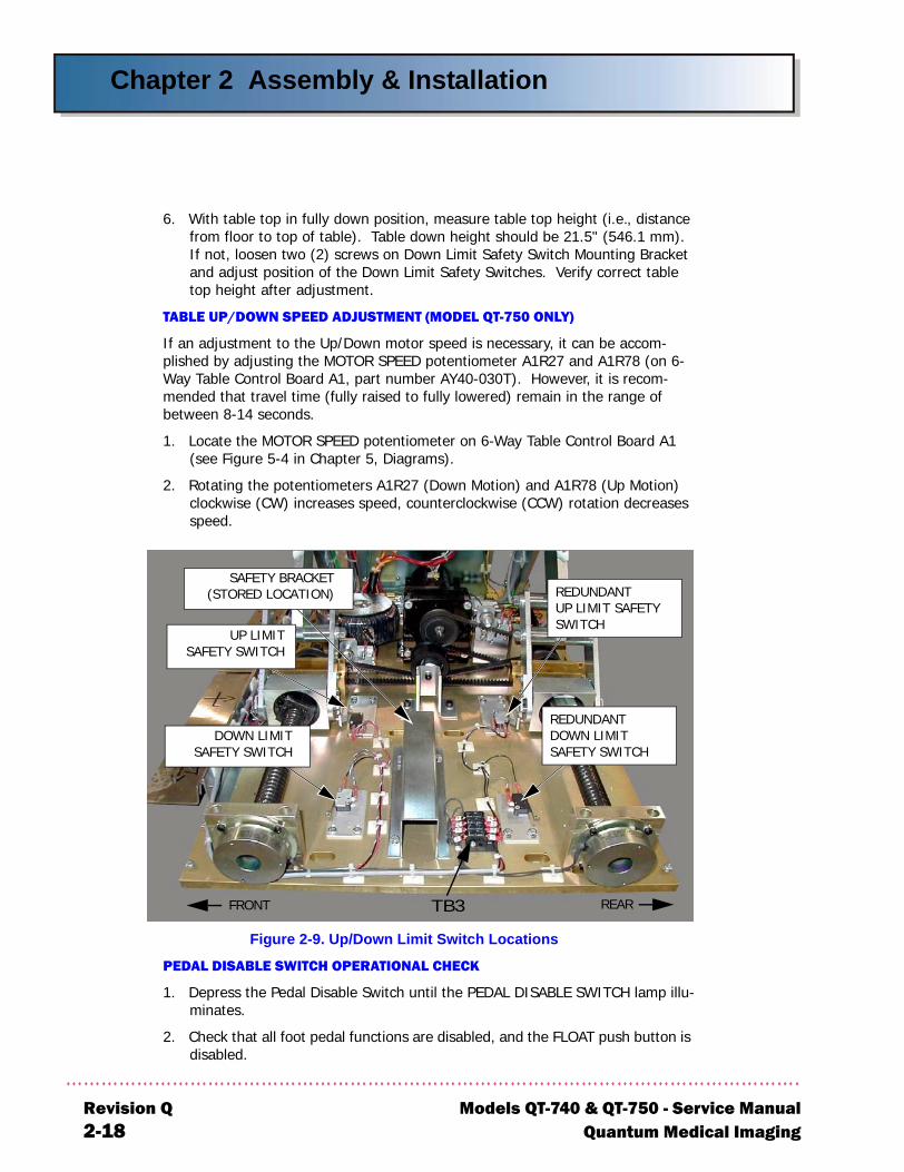
3. While running the table down, manually activate each Down Limit Safety Switch (S7 and S10, see Figure 2-9). The table should stop driving down.
4. While running the table up, manually activate each Up Limit Safety Switch (S8 and S9, see Figure 2-9). The table should stop driving up.
CAUTION! Table up/down height must be set tothe heights specified in the following steps. Failureto do so can cause damage to table components.
5. With table top in fully up position, measure table top height (i.e., distance from floor to top of table). Table up height should be 32" (812.8 mm). If not, loosen two (2) screws on Up Limit Safety Switch Mounting Bracket and adjust position of the Up Limit Safety Switches. Verify correct table top height after adjustment.
-740 & QT-750 - Service Manual Revision QMedical Imaging 2-17
Chapter 2 Assembly & Installation
Re2-
6. With table top in fully down position, measure table top height (i.e., distance from floor to top of table). Table down height should be 21.5" (546.1 mm). If not, loosen two (2) screws on Down Limit Safety Switch Mounting Bracket and adjust position of the Down Limit Safety Switches. Verify correct table top height after adjustment.
TABLE UP/DOWN SPEED ADJUSTMENT (MODEL QT-750 ONLY)
If an adjustment to the Up/Down motor speed is necessary, it can be accom-plished by adjusting the MOTOR SPEED potentiometer A1R27 and A1R78 (on 6-Way Table Control Board A1, part number AY40-030T). However, it is recom-mended that travel time (fully raised to fully lowered) remain in the range of between 8-14 seconds.
1. Locate the MOTOR SPEED potentiometer on 6-Way Table Control Board A1 (see Figure 5-4 in Chapter 5, Diagrams).
2. Rotating the potentiometers A1R27 (Down Motion) and A1R78 (Up Motion) clockwise (CW) increases speed, counterclockwise (CCW) rotation decreases speed.
Figure 2-9. Up/Down Limit Switch Locations
PEDAL DISABLE SWITCH OPERATIONAL CHECK
1. Depress the Pedal Disable Switch until the PEDAL DISABLE SWITCH lamp illu-minates.
2. Check that all foot pedal functions are disabled, and the FLOAT push button is disabled.
UP LIMITSAFETY SWITCH
DOWN LIMITSAFETY SWITCH
REDUNDANTUP LIMIT SAFETY SWITCH
REDUNDANTDOWN LIMIT SAFETY SWITCH
FRONT REARTB3
SAFETY BRACKET(STORED LOCATION)
vision Q Models QT-740 & QT-750 - Service Manual18 Quantum Medical Imaging
Chapter 2 Assembly & Installation
Models QTQuantum M
3. Depress the Pedal Disable Switch until switch lamp extinguishes.
4. Check that all pedal functions and the FLOAT push button are operational.
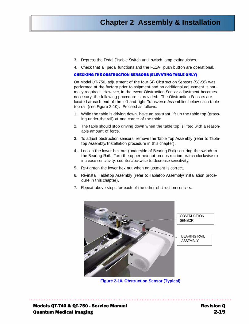
CHECKING THE OBSTRUCTION SENSORS (ELEVATING TABLE ONLY)
On Model QT-750, adjustment of the four (4) Obstruction Sensors (S3-S6) was performed at the factory prior to shipment and no additional adjustment is nor-mally required. However, in the event Obstruction Sensor adjustment becomes necessary, the following procedure is provided. The Obstruction Sensors are located at each end of the left and right Transverse Assemblies below each table-top rail (see Figure 2-10). Proceed as follows:
1. While the table is driving down, have an assistant lift up the table top (grasp-ing under the rail) at one corner of the table.
2. The table should stop driving down when the table top is lifted with a reason-able amount of force.
3. To adjust obstruction sensors, remove the Table Top Assembly (refer to Table-top Assembly/Installation procedure in this chapter).
4. Loosen the lower hex nut (underside of Bearing Rail) securing the switch to the Bearing Rail. Turn the upper hex nut on obstruction switch clockwise to increase sensitivity, counterclockwise to decrease sensitivity.
5. Re-tighten the lower hex nut when adjustment is correct.
6. Re-install Tabletop Assembly (refer to Tabletop Assembly/Installation proce-dure in this chapter).
7. Repeat above steps for each of the other obstruction sensors.
Figure 2-10. Obstruction Sensor (Typical)
OBSTRUCTION SENSOR
BEARING RAIL ASSEMBLY
-740 & QT-750 - Service Manual Revision Qedical Imaging 2-19
Chapter 2 Assembly & Installation
Re2-
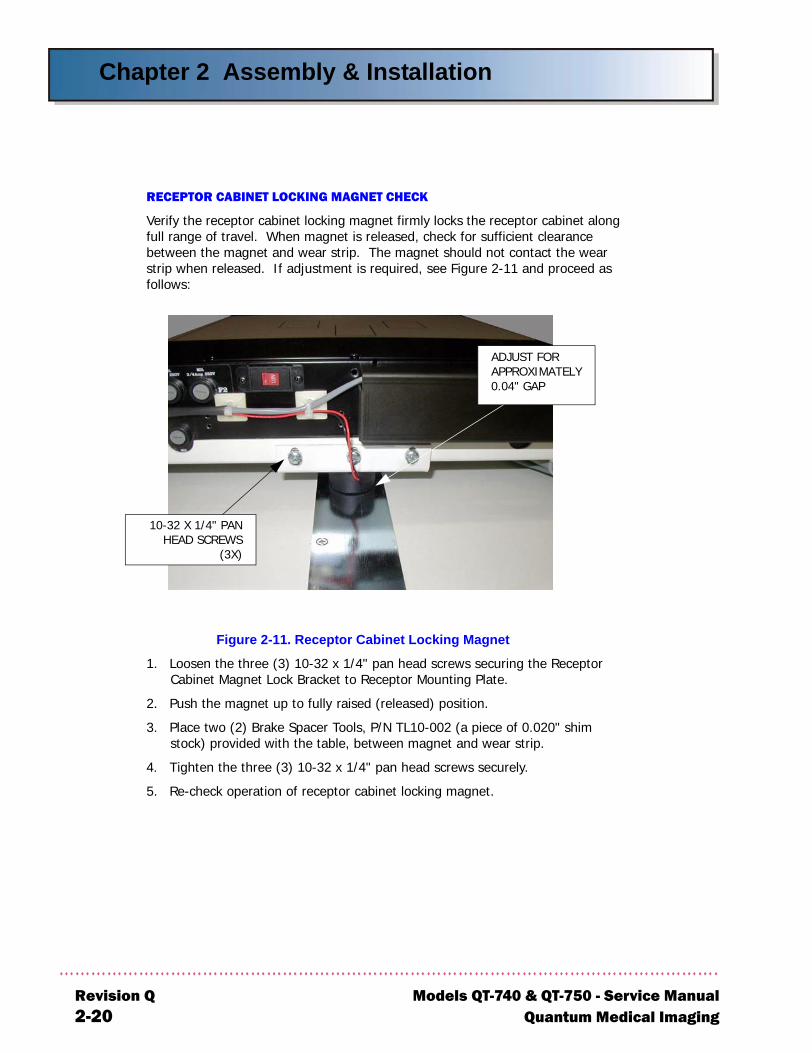
RECEPTOR CABINET LOCKING MAGNET CHECK
Verify the receptor cabinet locking magnet firmly locks the receptor cabinet along full range of travel. When magnet is released, check for sufficient clearance between the magnet and wear strip. The magnet should not contact the wear strip when released. If adjustment is required, see Figure 2-11 and proceed as follows:
Figure 2-11. Receptor Cabinet Locking Magnet
1. Loosen the three (3) 10-32 x 1/4" pan head screws securing the Receptor Cabinet Magnet Lock Bracket to Receptor Mounting Plate.
2. Push the magnet up to fully raised (released) position.
3. Place two (2) Brake Spacer Tools, P/N TL10-002 (a piece of 0.020" shim stock) provided with the table, between magnet and wear strip.
4. Tighten the three (3) 10-32 x 1/4" pan head screws securely.
5. Re-check operation of receptor cabinet locking magnet.
ADJUST FOR APPROXIMATELY 0.04" GAP
10-32 X 1/4" PANHEAD SCREWS
(3X)
vision Q Models QT-740 & QT-750 - Service Manual20 Quantum Medical Imaging
Chapter 2 Assembly & Installation
Models QTQuantum M
POSITIVE BEAM LIMITATION (PBL) COLLIMATORS
For Positive Beam Limitation (PBL) Collimators and Elevating Tables only, verify the Vertical SID Interlock feature is functioning properly as follows:
1. Place a 14" x 17" film cassette into the cassette tray and insert the cassette tray into the Receptor Cabinet.
2. Turn on power to the table.
3. Raise the table until it stops.
4. Position the collimator to 40" SID to table image receptor (40" SID LED indi-cator on tube stand handgrips should be illuminated).
5. The collimator should indicate it is ready for exposure.
6. Depress the DOWN foot pedal. The collimator should now indicate it is not ready for exposure.
7. Try to take an x-ray exposure and verify that no exposure is possible.
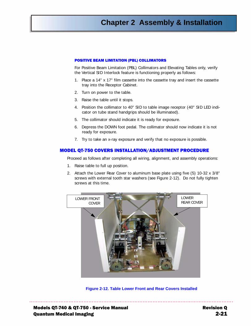
MODEL QT-750 COVERS INSTALLATION/ADJUSTMENT PROCEDURE
Proceed as follows after completing all wiring, alignment, and assembly operations:
1. Raise table to full up position.
2. Attach the Lower Rear Cover to aluminum base plate using five (5) 10-32 x 3/8" screws with external tooth star washers (see Figure 2-12). Do not fully tighten screws at this time.
Figure 2-12. Table Lower Front and Rear Covers Installed
LOWER REAR COVER
LOWER FRONTCOVER
-740 & QT-750 - Service Manual Revision Qedical Imaging 2-21
Chapter 2 Assembly & Installation
Re2-
3. Attach the Lower Front Cover to aluminum base plate using four (4) 10-32 x 3/8" screws with external tooth star washers (see Figure 2-12). Do not fully tighten screws at this time.
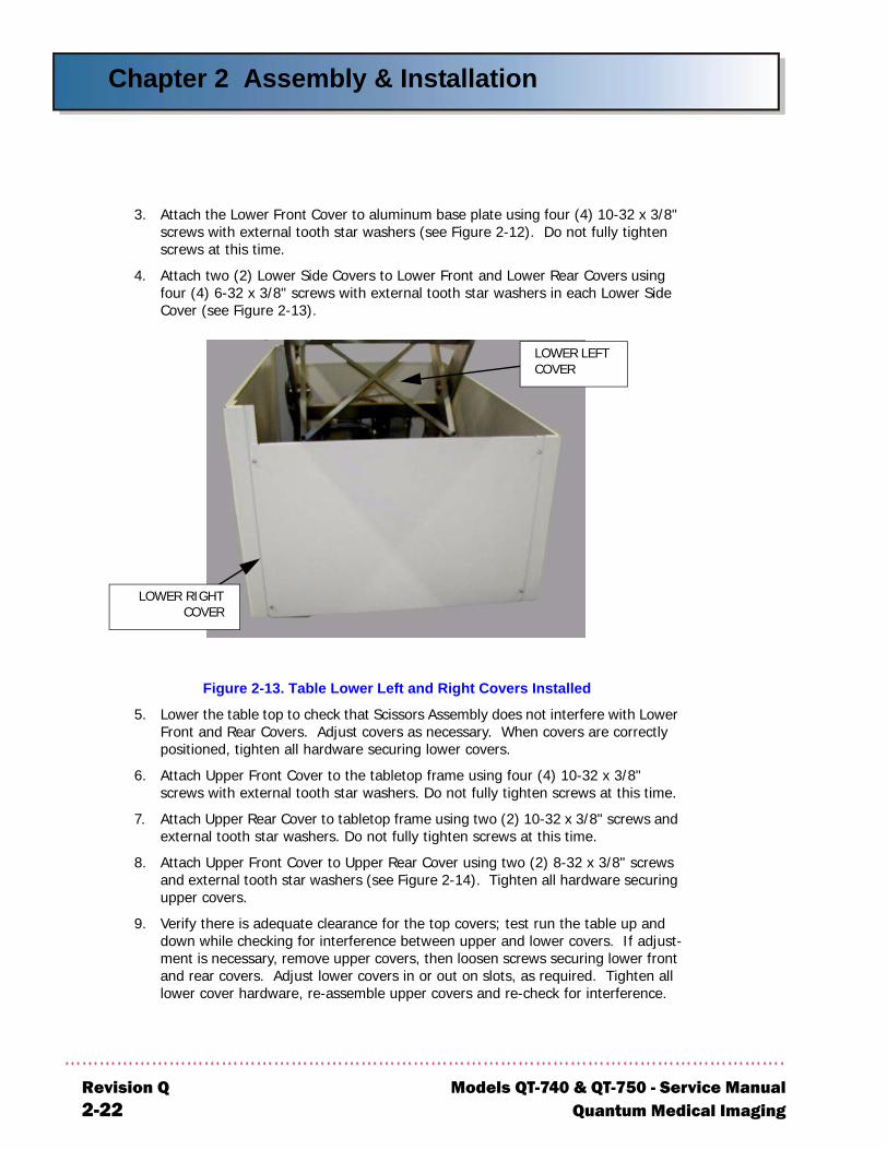
4. Attach two (2) Lower Side Covers to Lower Front and Lower Rear Covers using four (4) 6-32 x 3/8" screws with external tooth star washers in each Lower Side Cover (see Figure 2-13).
Figure 2-13. Table Lower Left and Right Covers Installed
5. Lower the table top to check that Scissors Assembly does not interfere with Lower Front and Rear Covers. Adjust covers as necessary. When covers are correctly positioned, tighten all hardware securing lower covers.
6. Attach Upper Front Cover to the tabletop frame using four (4) 10-32 x 3/8" screws with external tooth star washers. Do not fully tighten screws at this time.
7. Attach Upper Rear Cover to tabletop frame using two (2) 10-32 x 3/8" screws and external tooth star washers. Do not fully tighten screws at this time.
8. Attach Upper Front Cover to Upper Rear Cover using two (2) 8-32 x 3/8" screws and external tooth star washers (see Figure 2-14). Tighten all hardware securing upper covers.
9. Verify there is adequate clearance for the top covers; test run the table up and down while checking for interference between upper and lower covers. If adjust-ment is necessary, remove upper covers, then loosen screws securing lower front and rear covers. Adjust lower covers in or out on slots, as required. Tighten all lower cover hardware, re-assemble upper covers and re-check for interference.
LOWER LEFT COVER
LOWER RIGHTCOVER
vision Q Models QT-740 & QT-750 - Service Manual22 Quantum Medical Imaging
Chapter 2 Assembly & Installation
Models QTQuantum
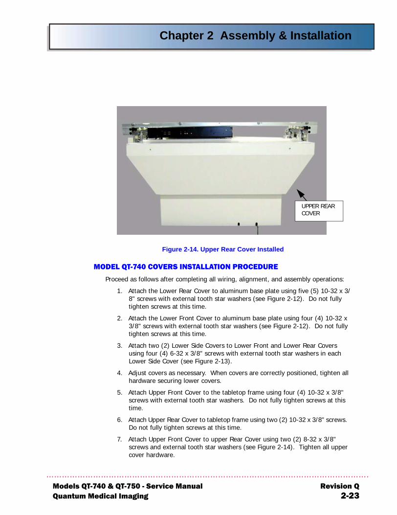
Figure 2-14. Upper Rear Cover Installed
MODEL QT-740 COVERS INSTALLATION PROCEDURE
Proceed as follows after completing all wiring, alignment, and assembly operations:
1. Attach the Lower Rear Cover to aluminum base plate using five (5) 10-32 x 3/8" screws with external tooth star washers (see Figure 2-12). Do not fully tighten screws at this time.
2. Attach the Lower Front Cover to aluminum base plate using four (4) 10-32 x 3/8" screws with external tooth star washers (see Figure 2-12). Do not fully tighten screws at this time.
3. Attach two (2) Lower Side Covers to Lower Front and Lower Rear Covers using four (4) 6-32 x 3/8" screws with external tooth star washers in each Lower Side Cover (see Figure 2-13).
4. Adjust covers as necessary. When covers are correctly positioned, tighten all hardware securing lower covers.
5. Attach Upper Front Cover to the tabletop frame using four (4) 10-32 x 3/8" screws with external tooth star washers. Do not fully tighten screws at this time.
6. Attach Upper Rear Cover to tabletop frame using two (2) 10-32 x 3/8" screws. Do not fully tighten screws at this time.
7. Attach Upper Front Cover to upper Rear Cover using two (2) 8-32 x 3/8" screws and external tooth star washers (see Figure 2-14). Tighten all upper cover hardware.
UPPER REAR COVER
-740 & QT-750 - Service Manual Revision QMedical Imaging 2-23

Chapter 2 Assembly & Installation
Re2-
THIS PAGE INTENTIONALLY LEFT BLANK
vision Q Models QT-740 & QT-750 - Service Manual24 Quantum Medical Imaging

Chapter
3-1
THEORYOF OPERATION
3

3-2
Chapter 3 Theory of Operation
Models QT-7Quantum M
NOTEThe table power supply cord is the power disconnect device. If hard wiring system power connection, the disconnect device is facility-provided external circuit breaker or shut-off switch.
OVERVIEW
Model QT-740 and QT-750 radiographic tables feature a tabletop that "floats" in four directions for transverse and longitudinal patient positioning. The tabletop of ModelQT-750 can also be raised and lowered.
The tabletop floats (rides) on 30 bearings; 26 provide longitudinal tabletop motion, and four are provided for transverse (forward and backward) tabletop motion. The longitudi-nal bearings are bolted to two precision-machined stainless steel bearing bars, which are mounted below the tabletop on the front and back sides of the table. Four 1-5/8" load bearings bolted on the Transverse Carriage Assembly permit transverse travel of the tabletop. Eight anti-racking and four anti-tipping guide bearings, bolted to the Transverse Carriage Assembly, stabilize tabletop transverse motion by controlling movement of the left and right Transverse Rails.
Two fail-safe brakes (24 VDC electromagnets) are positioned extremely close to the bear-ing bars. When the electromagnets are de-activated (i.e., FLOAT foot pedal/push button is not pressed), the fail-safe brakes "grab" the bearing bar securely, locking the longitudi-nal travel of the table. Similarly, four fail-safe brakes (24 VDC electromagnets) are used to grab the Transverse Rails, locking the transverse travel of the table. Depressing either the FLOAT foot pedal(s) or FLOAT push button energizes the electromagnets, releasing the fail-safe brakes and allowing the tabletop to float freely both longitudinally and trans-versely.
The Receptor Cabinet rides on four linear ball-bearings mounted to adjustable brackets attached to either side of the cabinet. These bearings travel on the hardened and pol-ished steel shafts of the Receptor Cabinet Carriage. One electromagnet on the underside of the housing "locks" the Receptor Cabinet into place until the Receptor Cabinet Lock Release switch is depressed, thereby releasing the magnet's hold and allowing free move-ment of the Receptor Cabinet.
The following paragraphs provide theory of operation for Model QT-740 and ModelQT-750 radiographic tables.
MODEL QT-740 TABLE
The table's major electrical components include the AC transformer and fuse block, printed circuit boards, and magnetic locks. See Figures 5-1 and 5-3 in Chapter 5, Dia-grams.
Power Distribution
115/230 VAC line input is applied through fuses F1 and F2 to step-down trans-former T1. Transformer T1 provides 18 VAC to 4-Way Table Control Board con-nector A1J1-1 and A1J1-2. The 18 VAC input is applied to full-wave bridge rectifier A1DB1, filtered by A1C1 and A1R1, and applied through resistor A1R2 and zener diode A1D1 to produce +12 VDC. The +24 VDC output of A1DB1 is connected to A1J1-6 and A1J1-10 to provide +24 VDC to the bucky, transverse, and longitudinal electromagnets.
40 & QT-750 - Service Manual Revision Qedical Imaging, LLC 3-3
Chapter 3 Theory of Operation
R3
Float Control
Model QT-740 tables have one foot pedal and one push button switch (located on the Operator Control Handle Assembly) that control four-way float top operation. Pressing the foot pedal operates switches S1 and S2, and pressing the push but-ton switch operates switch S3. When S1, S2, or S3 is activated, a negative-going level is applied through normally open (N.O.) PEDAL DISABLE switch S4 and FLOAT switch S1, S2, or S3 to A1C3, which generates a negative-going pulse at one-shot A1U1-2 on 4-Way Table Control Board A1. One-shot A1U1-3 produces a 47-second pulse that turns on FET A1Q1, which provides drive current for the +24 VDC transverse and longitudinal electromagnets. The magnets release the mechanical brakes, allowing tabletop "float" motion. After 47 seconds, or releas-ing the FLOAT foot pedal or push button (which applies a negative-going level to A1U1-4, resetting A1U1) A1Q1 turns off. The magnets de-energize and lock pre-venting tabletop "float" motion.
Foot Pedal Disable Circuit
A Foot Pedal Disable Switch S4 is located below the table rail on the left end of the table. Pressing the switch until PEDAL DISABLE SWITCH lamp DS2 is illumi-nated disconnects FLOAT switches S1, S2, and S3 thereby disabling FLOAT foot pedal and FLOAT push button operation. When the patient is in the correct loca-tion for x-ray, disabling the FLOAT foot pedal push button prevents inadvertent activation of the pedal. When Foot Pedal Disable Switch lamp DS2 is not illumi-nated, the FLOAT foot pedal and push button are fully operational.
Receptor Cabinet Lock
The Receptor Cabinet magnetic lock has its own release switch (S5) for Receptor Cabinet positioning. When S5 is pressed, the Receptor Cabinet locking magnet is de-energized enabling cabinet movement.
MODEL QT-750 TABLE
The table's major electrical components include the AC transformer and fuse block, printed circuit boards, magnetic locks, and DC motor. Vertical table motion is per-formed by a motor-driven twin lead screw assembly mounted on the table base. The DC motor drives the twin lead screw assembly via belt connection, which extends (upward) and retracts (downward) the Scissors Assembly when the UP or DOWN foot pedal, respectively, is depressed. See Figures 5-2 and 5-4 in Chapter 5, Diagrams.
Power Distribution
115/230 VAC line input is applied through terminal board TB1, fuses F1 and F2, and line filter FL1 and to AC transformer T1. Transformer T1 provides 20 VAC to 6-Way Table Control Board A1. Transformer T1 also provides 110 VAC to DC Motor Driver A2 (AC terminals) and to 6-Way Table Control Board connector A1J1-15 and A1J1-16.
evision Q Models QT-740 & QT-750 - Service Manual-4 Quantum Medical Imaging, LLC
Chapter 3 Theory of Operation
Models QT-7Quantum M
Voltage Regulation
From AC transformer T1, 20 VAC is supplied to 6-Way Table Control Board A1 at connector pins A1J5-1 and A1J5-3 (see Figure 5-2). Fuse protection for 20 VAC input is provided by fuse A1F2.
Float Control
Model QT-750 tables have two FLOAT foot pedals, which operate switches S11 and S12 and a FLOAT push button switch (S13) located on the Operator Control Handle Assembly, attached to the tabletop accessory rail. When S11, S12, or S13 is activated, a low FLOAT signal is applied through 6-Way Table Control Board connector A1J2-18. This signal triggers a one-shot that produces a 47 second pulse, which provides drive current for the +24 VDC transverse and longitudinal electromagnets. The magnets release the mechanical brakes allowing tabletop "float" motion. When the FLOAT push button is released, or after 47 seconds of continuous activation (i.e., after the one-shot times out) the magnets are de-energized and the fail-safe brakes lock, inhibiting tabletop "float" motion.
Foot Pedal Disable Switch
Foot Pedal Disable Switch S14 is located below the table rail on the left end of the table. Pressing the switch until the PEDAL DISABLE SWITCH lamp DS2 is illumi-nated disables foot pedal operation. When the patient is in the correct location for x-ray, disabling the foot pedals prevents inadvertent activation of the pedals. When the Foot Pedal Disable Switch lamp DS2 is not illuminated, the foot pedals are fully operational.
Positive Beam Limitation
When the table is used in a PBL system, the UP LIMIT signal is used to prevent exposures when the table is not in its full up position (i.e., at 40" SID). Relay A1K8 is energized when the table is at its maximum up position (as indicated when the /UP LIMIT signal is active low) to indicate the 40" SID position via relay contact closure at A1J4-1 and A1J4-2. This contact closure is then fed to the table's PBL circuit to indicate the 40" SID position.
Receptor Cabinet Lock
The Receptor Cabinet magnetic lock has its own release switch (S15) for Receptor Cabinet positioning. When S15 is pressed, the Receptor Cabinet locking magnet is de-energized enabling cabinet movement.
Emergency Stop Switch
The Emergency Stop switch (S16) is a two-position push-button switch connected across the 110 VAC secondary of transformer T1. Pressing the switch breaks the 110 VAC input connection applied to DC Motor Driver Board A2 (at one AC termi-nal) thereby removing power from the table DC motor drive circuit. To restore power, the switch must be manually released to the normally closed position.
40 & QT-750 - Service Manual Revision Qedical Imaging, LLC 3-5
Chapter 3 Theory of Operation
R3
In addition to providing an emergency shut-off function, the Emergency Stop Switch serves as an indicator lamp that flashes at a 1-Hertz rate in the event one of the following "faults" occur:
• Any of the obstruction sensors (S3 - S6) are activated (during tabletop down movement)
• A drive belt fault condition occurs (i.e. snapped or disengaged belt), sensed by normally-closed MOTOR BELT switch S22
• A sync belt fault condition occurs (i.e. snapped or disengaged belt), sensed by normally-closed SYNC BELT switch S23
• DC Motor over-temperature fault occurs (motor temperature exceeds 70°C), sensed by DC Motor thermal switch S21
• The 20 VAC input from transformer T1 falls below 15% nominal
• Redundant down limit switch S10 or redundant up limit switch S8 is activated
When any of the above conditions occur, a low-to-high transition is applied to a1-Hz square wave oscillator/transistor circuit on Table Control Board A1, which generates the FL+EM SW signal that drives the EMERGENCY SWITCH LAMP DS1 through connector A1J2-20.
evision Q Models QT-740 & QT-750 - Service Manual-6 Quantum Medical Imaging, LLC
Chapter
4-1
SERVICEINSTRUCTIONS
4

4-2
Chapter 4 Service Instructions
Models QT-7Quantum M
OVERVIEW
This chapter provides instructions to assist the service technician in maintaining the smooth operation of the table. The table will function reliably when maintained according to the instructions provided in this chapter. Only properly trained service personnel should service or maintain this equipment. Safe equipment performance requires the attention of service personnel who are specifically trained and experi-enced with medical x-ray apparatus. Applicable preventive maintenance or any repair service should be performed by these skilled individuals. Failure to follow manufac-turer’s or service personnel’s recommendations may result in serious injury.
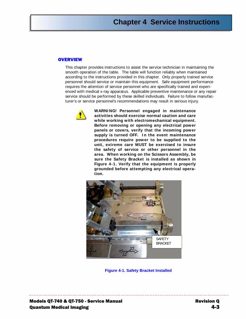
WARNING! Personnel engaged in maintenanceactivities should exercise normal caution and carewhile working with electromechanical equipment.Before removing or opening any electrical powerpanels or covers, verify that the incoming powersupply is turned OFF. In the event maintenanceprocedures require power to be supplied to theunit, extreme care MUST be exercised to insurethe safety of service or other personnel in thearea. When working on the Scissors Assembly, besure the Safety Bracket is installed as shown inFigure 4-1. Verify that the equipment is properlygrounded before attempting any electrical opera-tion.
Figure 4-1. Safety Bracket Installed
SAFETY BRACKET
40 & QT-750 - Service Manual Revision Qedical Imaging 4-3
Chapter 4 Service Instructions
R4
SERVICE MAINTENANCE
WARNING! Always disconnect the equipmentfrom the main power supply prior to any cleaning.
Visual Inspection
A complete series of inspections and functional checks was conducted at installation to insure proper operation of the system. The following inspection and adjustment procedures are recommended to maintain the system in its original operating condition.
Perform Every Six Months:
•Check for evidence of loose hardware or loose wires
•Check all bearings and bearing surfaces for cleanliness and corrosion
•Clean Bearing Tracks
•Conduct a general inspection for worn or damaged parts
•Inspect Drive and Sync belts for wear, cracks, looseness
•Check for smoothness of Receptor Cabinet motion
•Verify that all ground conductors are properly and securely installed and free of corrosion or damage
•Check all electrical cabling and wiring for wear and fraying
•Perform a functional test and check table vertical travel (Model QT-750 only)
•Perform float top locking magnet operational check (refer to "Float Top Locking Magnet Check" procedure in this chapter)
•Check external covers for proper fit; inspect for scratches that may indicate cover misalignment or damage caused by collisions with footstools, trolleys, or other equipment
Functional Check for Model QT-750 Elevating Tables
1. Raise the table to the full up position and then turn power off.
2. Remove the upper and lower covers from the table.
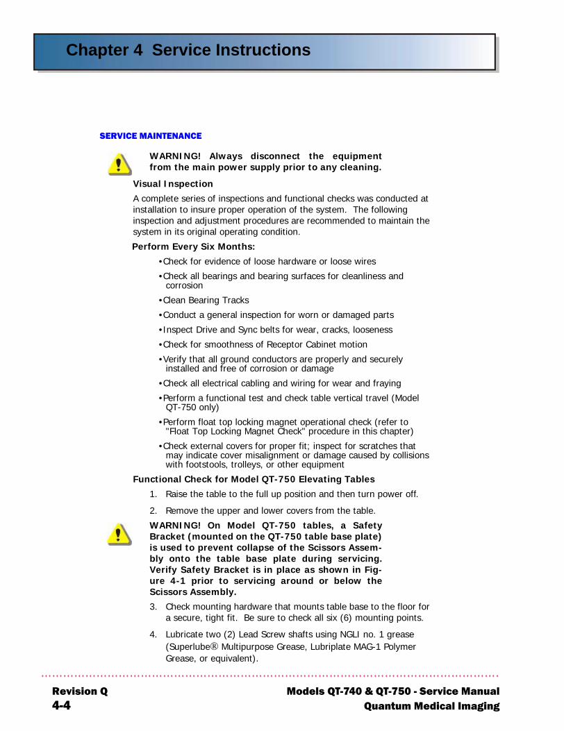
WARNING! On Model QT-750 tables, a SafetyBracket (mounted on the QT-750 table base plate)is used to prevent collapse of the Scissors Assem-bly onto the table base plate during servicing.Verify Safety Bracket is in place as shown in Fig-ure 4-1 prior to servicing around or below theScissors Assembly.
3. Check mounting hardware that mounts table base to the floor for a secure, tight fit. Be sure to check all six (6) mounting points.
4. Lubricate two (2) Lead Screw shafts using NGLI no. 1 grease (Superlube® Multipurpose Grease, Lubriplate MAG-1 Polymer Grease, or equivalent).
evision Q Models QT-740 & QT-750 - Service Manual-4 Quantum Medical Imaging
Chapter 4 Service Instructions
Models QT-7Quantum M
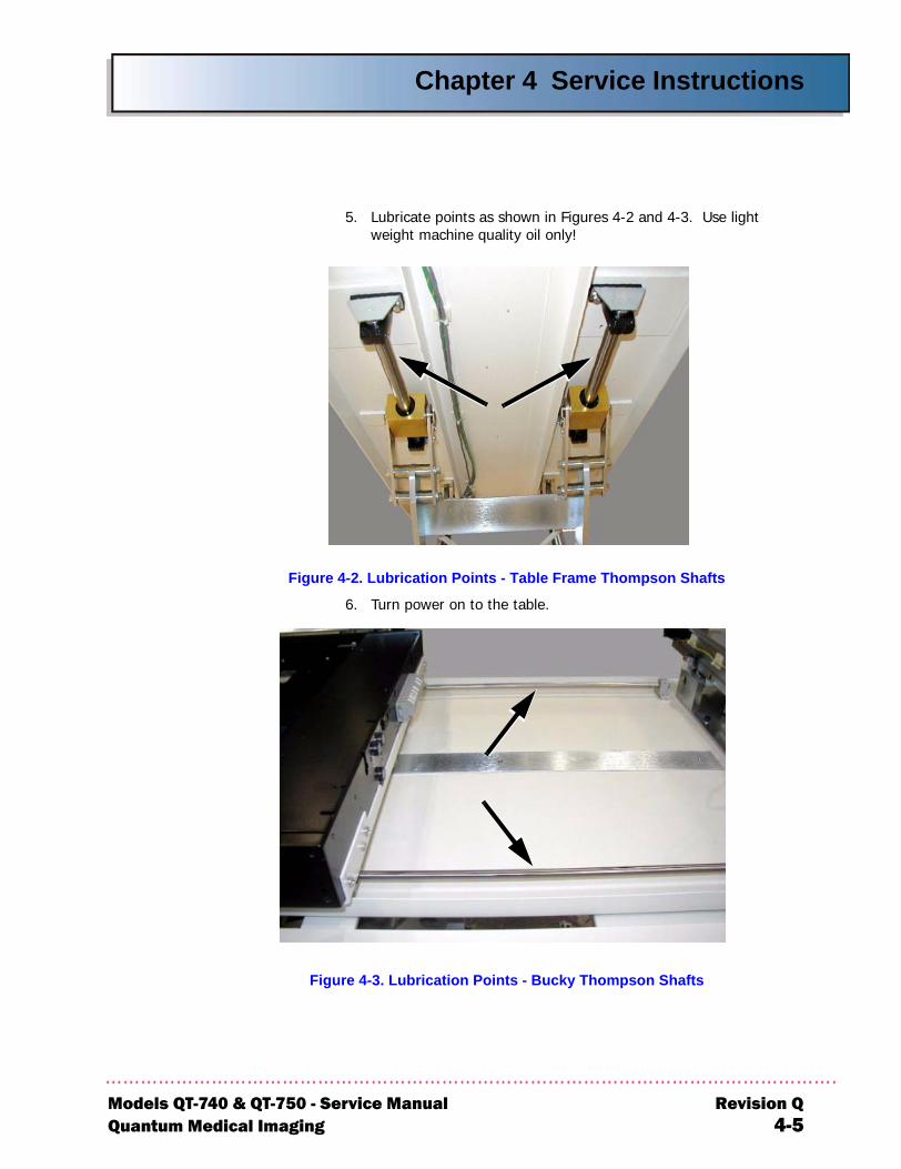
5. Lubricate points as shown in Figures 4-2 and 4-3. Use light weight machine quality oil only!
Figure 4-2. Lubrication Points - Table Frame Thompson Shafts
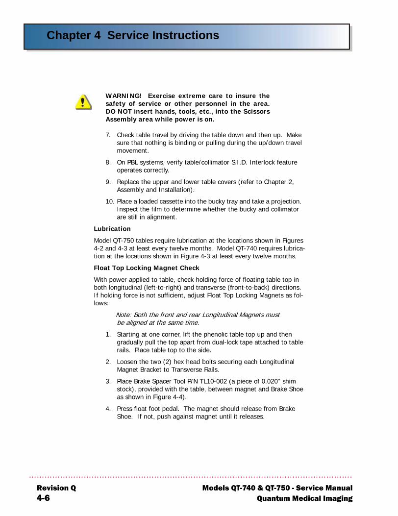
6. Turn power on to the table.
Figure 4-3. Lubrication Points - Bucky Thompson Shafts
40 & QT-750 - Service Manual Revision Qedical Imaging 4-5
Chapter 4 Service Instructions
R4
WARNING! Exercise extreme care to insure thesafety of service or other personnel in the area.DO NOT insert hands, tools, etc., into the ScissorsAssembly area while power is on.
7. Check table travel by driving the table down and then up. Make sure that nothing is binding or pulling during the up/down travel movement.
8. On PBL systems, verify table/collimator S.I.D. Interlock feature operates correctly.
9. Replace the upper and lower table covers (refer to Chapter 2, Assembly and Installation).
10. Place a loaded cassette into the bucky tray and take a projection. Inspect the film to determine whether the bucky and collimator are still in alignment.
Lubrication
Model QT-750 tables require lubrication at the locations shown in Figures 4-2 and 4-3 at least every twelve months. Model QT-740 requires lubrica-tion at the locations shown in Figure 4-3 at least every twelve months.
Float Top Locking Magnet Check
With power applied to table, check holding force of floating table top in both longitudinal (left-to-right) and transverse (front-to-back) directions. If holding force is not sufficient, adjust Float Top Locking Magnets as fol-lows:
Note: Both the front and rear Longitudinal Magnets must be aligned at the same time.
1. Starting at one corner, lift the phenolic table top up and then gradually pull the top apart from dual-lock tape attached to table rails. Place table top to the side.
2. Loosen the two (2) hex head bolts securing each Longitudinal Magnet Bracket to Transverse Rails.
3. Place Brake Spacer Tool P/N TL10-002 (a piece of 0.020" shim stock), provided with the table, between magnet and Brake Shoe as shown in Figure 4-4).
4. Press float foot pedal. The magnet should release from Brake Shoe. If not, push against magnet until it releases.
evision Q Models QT-740 & QT-750 - Service Manual-6 Quantum Medical Imaging
Chapter 4 Service Instructions
Models QT-7Quantum M
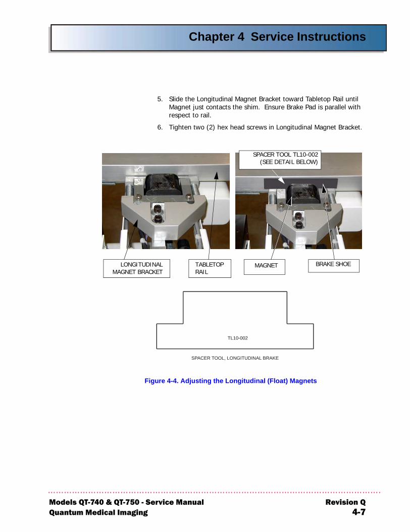
5. Slide the Longitudinal Magnet Bracket toward Tabletop Rail until Magnet just contacts the shim. Ensure Brake Pad is parallel with respect to rail.
6. Tighten two (2) hex head screws in Longitudinal Magnet Bracket.
Figure 4-4. Adjusting the Longitudinal (Float) Magnets
LONGITUDINALMAGNET BRACKET
TABLETOPRAIL
SPACER TOOL, LONGITUDINAL BRAKE
TL10-002
MAGNET
SPACER TOOL TL10-002(SEE DETAIL BELOW)
BRAKE SHOE
40 & QT-750 - Service Manual Revision Qedical Imaging 4-7
Chapter 4 Service Instructions
R4
-cur-
at di-n
en-
n-
sen-
sen-
l" nor-on.
" up al
TROUBLESHOOTING PROCEDURE
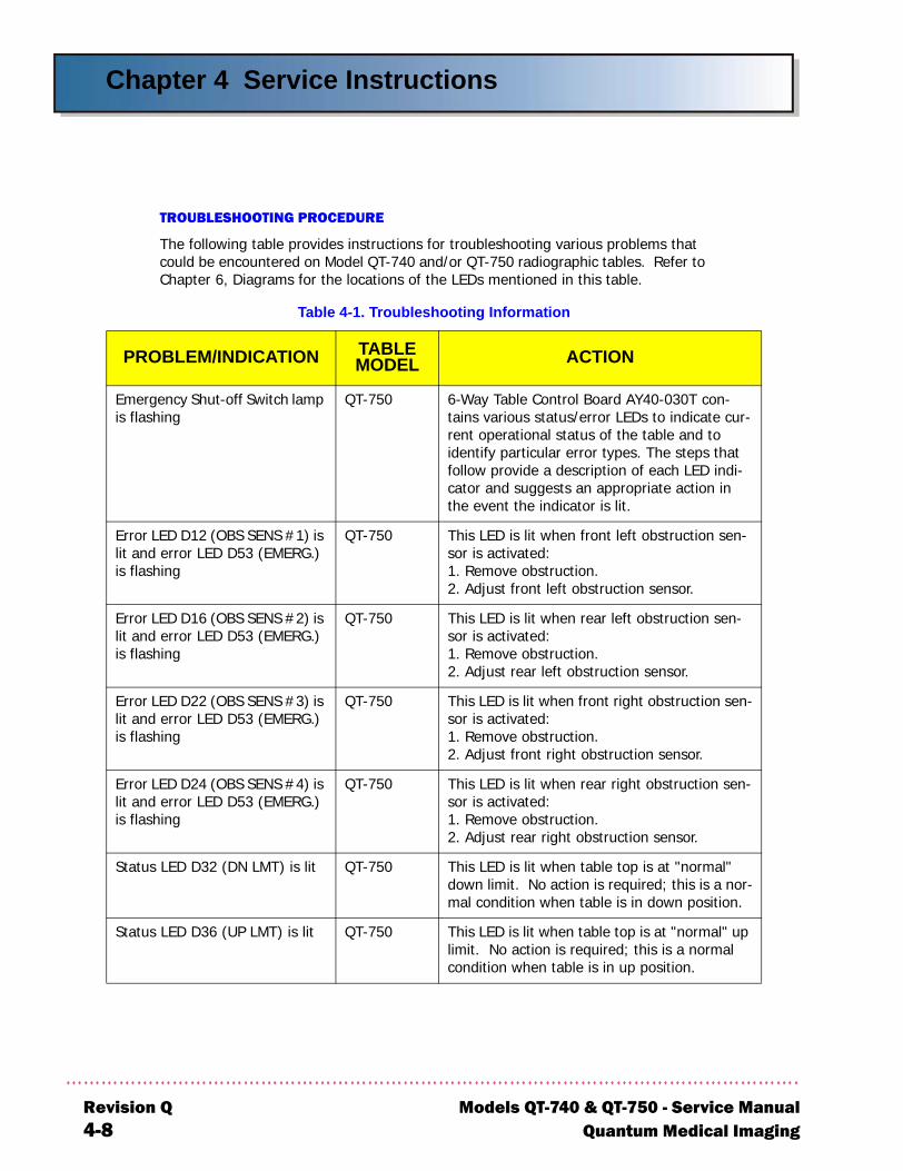
The following table provides instructions for troubleshooting various problems that could be encountered on Model QT-740 and/or QT-750 radiographic tables. Refer to Chapter 6, Diagrams for the locations of the LEDs mentioned in this table.
Table 4-1. Troubleshooting Information
PROBLEM/INDICATION TABLE MODEL ACTION
Emergency Shut-off Switch lamp is flashing
QT-750 6-Way Table Control Board AY40-030T contains various status/error LEDs to indicate rent operational status of the table and to identify particular error types. The steps thfollow provide a description of each LED incator and suggests an appropriate action ithe event the indicator is lit.
Error LED D12 (OBS SENS #1) is lit and error LED D53 (EMERG.) is flashing
QT-750 This LED is lit when front left obstruction ssor is activated:1. Remove obstruction.2. Adjust front left obstruction sensor.
Error LED D16 (OBS SENS #2) is lit and error LED D53 (EMERG.) is flashing
QT-750 This LED is lit when rear left obstruction sesor is activated:1. Remove obstruction.2. Adjust rear left obstruction sensor.
Error LED D22 (OBS SENS #3) is lit and error LED D53 (EMERG.) is flashing
QT-750 This LED is lit when front right obstruction sor is activated:1. Remove obstruction.2. Adjust front right obstruction sensor.
Error LED D24 (OBS SENS #4) is lit and error LED D53 (EMERG.) is flashing
QT-750 This LED is lit when rear right obstruction sor is activated:1. Remove obstruction.2. Adjust rear right obstruction sensor.
Status LED D32 (DN LMT) is lit QT-750 This LED is lit when table top is at "normadown limit. No action is required; this is a mal condition when table is in down positi
Status LED D36 (UP LMT) is lit QT-750 This LED is lit when table top is at "normallimit. No action is required; this is a normcondition when table is in up position.
evision Q Models QT-740 & QT-750 - Service Manual-8 Quantum Medical Imaging
Chapter 4 Service Instructions
Models QT-Quantum M
Status L
Status L
Error LEerror LEflashing
Error LEsteady switch i
PROB
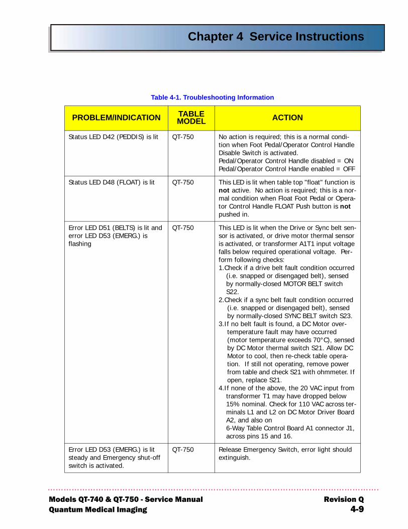
ED D42 (PEDDIS) is lit QT-750 No action is required; this is a normal condi-tion when Foot Pedal/Operator Control Handle Disable Switch is activated.Pedal/Operator Control Handle disabled = ONPedal/Operator Control Handle enabled = OFF
ED D48 (FLOAT) is lit QT-750 This LED is lit when table top "float" function is not active. No action is required; this is a nor-mal condition when Float Foot Pedal or Opera-tor Control Handle FLOAT Push button is not pushed in.
D D51 (BELTS) is lit and D D53 (EMERG.) is
QT-750 This LED is lit when the Drive or Sync belt sen-sor is activated, or drive motor thermal sensor is activated, or transformer A1T1 input voltage falls below required operational voltage. Per-form following checks:1.Check if a drive belt fault condition occurred
(i.e. snapped or disengaged belt), sensed by normally-closed MOTOR BELT switch S22.
2.Check if a sync belt fault condition occurred (i.e. snapped or disengaged belt), sensed by normally-closed SYNC BELT switch S23.
3.If no belt fault is found, a DC Motor over-temperature fault may have occurred (motor temperature exceeds 70°C), sensed by DC Motor thermal switch S21. Allow DC Motor to cool, then re-check table opera-tion. If still not operating, remove power from table and check S21 with ohmmeter. If open, replace S21.
4.If none of the above, the 20 VAC input from transformer T1 may have dropped below 15% nominal. Check for 110 VAC across ter-minals L1 and L2 on DC Motor Driver Board A2, and also on6-Way Table Control Board A1 connector J1, across pins 15 and 16.
D D53 (EMERG.) is lit and Emergency shut-off s activated.
QT-750 Release Emergency Switch, error light should extinguish.
Table 4-1. Troubleshooting Information
LEM/INDICATION TABLE MODEL ACTION
740 & QT-750 - Service Manual Revision Qedical Imaging 4-9
Chapter 4 Service Instructions
R4
down itch ble ent of wn nt, de-(i.e., as ormal
d (i.e., A1R27 on 6-- to tween
s (i.e., is g
ch is indi-ing).nnec-n foot d
ay (pins 14 to
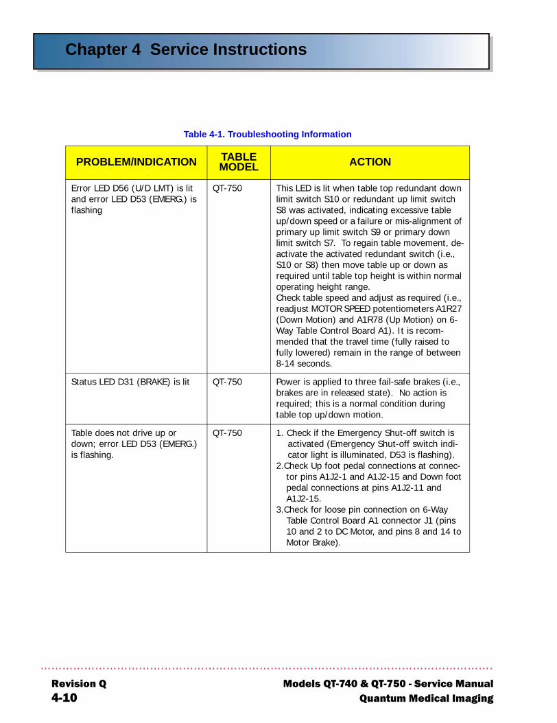
Error LED D56 (U/D LMT) is lit and error LED D53 (EMERG.) is flashing
QT-750 This LED is lit when table top redundantlimit switch S10 or redundant up limit swS8 was activated, indicating excessive taup/down speed or a failure or mis-alignmprimary up limit switch S9 or primary dolimit switch S7. To regain table movemeactivate the activated redundant switch S10 or S8) then move table up or downrequired until table top height is within noperating height range.Check table speed and adjust as requirereadjust MOTOR SPEED potentiometers (Down Motion) and A1R78 (Up Motion) Way Table Control Board A1). It is recommended that the travel time (fully raisedfully lowered) remain in the range of be8-14 seconds.
Status LED D31 (BRAKE) is lit QT-750 Power is applied to three fail-safe brakebrakes are in released state). No actionrequired; this is a normal condition durintable top up/down motion.
Table does not drive up or down; error LED D53 (EMERG.) is flashing.
QT-750 1. Check if the Emergency Shut-off switactivated (Emergency Shut-off switchcator light is illuminated, D53 is flash
2.Check Up foot pedal connections at cotor pins A1J2-1 and A1J2-15 and Dowpedal connections at pins A1J2-11 anA1J2-15.
3.Check for loose pin connection on 6-WTable Control Board A1 connector J1 10 and 2 to DC Motor, and pins 8 andMotor Brake).
Table 4-1. Troubleshooting Information
PROBLEM/INDICATION TABLE MODEL ACTION
evision Q Models QT-740 & QT-750 - Service Manual-10 Quantum Medical Imaging
Chapter 4 Service Instructions
Models QT-7Quantum M
Table dodown; enot flas
PROB
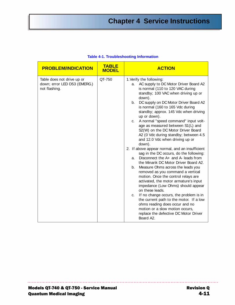
es not drive up or rror LED D53 (EMERG.)
hing.
QT-750 1.Verify the following:a. AC supply to DC Motor Driver Board A2
is normal (110 to 120 VAC during standby; 100 VAC when driving up or down).
b. DC supply on DC Motor Driver Board A2 is normal (160 to 165 Vdc during standby; approx. 145 Vdc when driving up or down).
c. A normal "speed command" input volt-age as measured between S1(L) and S2(W) on the DC Motor Driver Board A2 (0 Vdc during standby; between 4.5 and 12.0 Vdc when driving up or down).
2. If above appear normal, and an insufficient sag in the DC occurs, do the following:
a. Disconnect the A+ and A- leads from the Minarik DC Motor Driver Board A2.
b. Measure Ohms across the leads you removed as you command a vertical motion. Once the control relays are activated, the motor armature's input impedance (Low Ohms) should appear on these leads.
c. If no change occurs, the problem is in the current path to the motor. If a low ohms reading does occur and no motion or a slow motion occurs, replace the defective DC Motor Driver Board A2.
Table 4-1. Troubleshooting Information
LEM/INDICATION TABLE MODEL ACTION
40 & QT-750 - Service Manual Revision Qedical Imaging 4-11
Chapter 4 Service Instructions
R4
h is indi-ing).) and oard
Table and 3. Table and 8 r J3 ).ay
e at
er.AC 0 vac con-switch
ay pins 1
Table and 9.-Way
ectro-
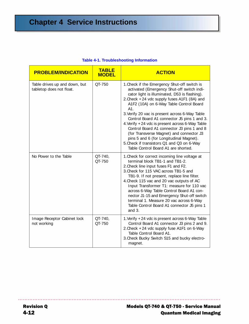
Table drives up and down, but tabletop does not float.
QT-750 1.Check if the Emergency Shut-off switcactivated (Emergency Shut-off switchcator light is illuminated, D53 is flash
2.Check +24 vdc supply fuses A1F1 (8AA1F2 (10A) on 6-Way Table Control BA1.
3.Verify 20 vac is present across 6-Way Control Board A1 connector J5 pins 1
4.Verify +24 vdc is present across 6-WayControl Board A1 connector J3 pins 1(for Transverse Magnet) and connectopins 5 and 6 (for Longitudinal Magnet
5.Check if transistors Q1 and Q3 on 6-WTable Control Board A1 are shorted.
No Power to the Table QT-740,QT-750
1.Check for correct incoming line voltagterminal block TB1-1 and TB1-2.
2.Check line input fuses F1 and F2.3.Check for 115 VAC across TB1-5 and
TB1-9. If not present, replace line filt4.Check 115 vac and 20 vac outputs of
Input Transformer T1: measure for 11across 6-Way Table Control Board A1 nector J1-15 and Emergency Shut-off terminal 1. Measure 20 vac across 6-WTable Control Board A1 connector J5 and 3.
Image Receptor Cabinet lock not working
QT-740,QT-750
1.Verify +24 vdc is present across 6-WayControl Board A1 connector J3 pins 2
2.Check +24 vdc supply fuse A1F1 on 6Table Control Board A1.
3.Check Bucky Switch S15 and bucky elmagnet.
Table 4-1. Troubleshooting Information
PROBLEM/INDICATION TABLE MODEL ACTION
evision Q Models QT-740 & QT-750 - Service Manual-12 Quantum Medical Imaging
Chapter 4 Service Instructions
Models QT-7Quantum M
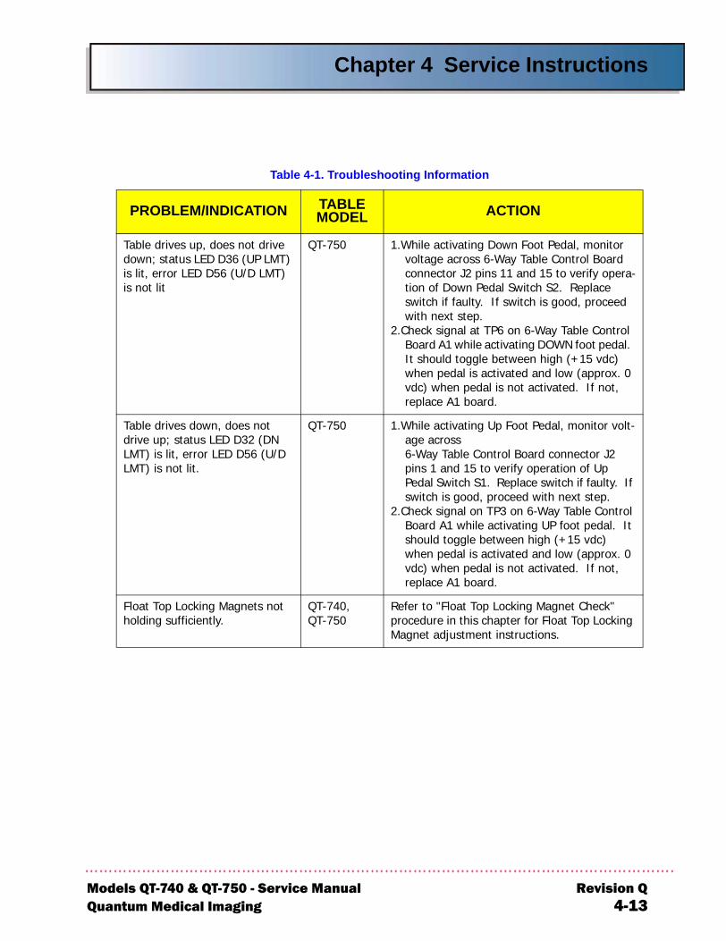
Table drdown; sis lit, eris not lit
Table drdrive upLMT) isLMT) is
Float Toholding
PROB
ives up, does not drive tatus LED D36 (UP LMT) ror LED D56 (U/D LMT)
QT-750 1.While activating Down Foot Pedal, monitor voltage across 6-Way Table Control Board connector J2 pins 11 and 15 to verify opera-tion of Down Pedal Switch S2. Replace switch if faulty. If switch is good, proceed with next step.
2.Check signal at TP6 on 6-Way Table Control Board A1 while activating DOWN foot pedal. It should toggle between high (+15 vdc) when pedal is activated and low (approx. 0 vdc) when pedal is not activated. If not, replace A1 board.
ives down, does not ; status LED D32 (DN
lit, error LED D56 (U/D not lit.
QT-750 1.While activating Up Foot Pedal, monitor volt-age across6-Way Table Control Board connector J2 pins 1 and 15 to verify operation of Up Pedal Switch S1. Replace switch if faulty. If switch is good, proceed with next step.
2.Check signal on TP3 on 6-Way Table Control Board A1 while activating UP foot pedal. It should toggle between high (+15 vdc) when pedal is activated and low (approx. 0 vdc) when pedal is not activated. If not, replace A1 board.
p Locking Magnets not sufficiently.
QT-740,QT-750
Refer to "Float Top Locking Magnet Check" procedure in this chapter for Float Top Locking Magnet adjustment instructions.
Table 4-1. Troubleshooting Information
LEM/INDICATION TABLE MODEL ACTION
40 & QT-750 - Service Manual Revision Qedical Imaging 4-13
Chapter 4 Service Instructions
R4
REMOVAL/REPLACEMENT PROCEDURES
The following procedures provide step-by-step instructions for removal and replacement of the repairable components in the table.
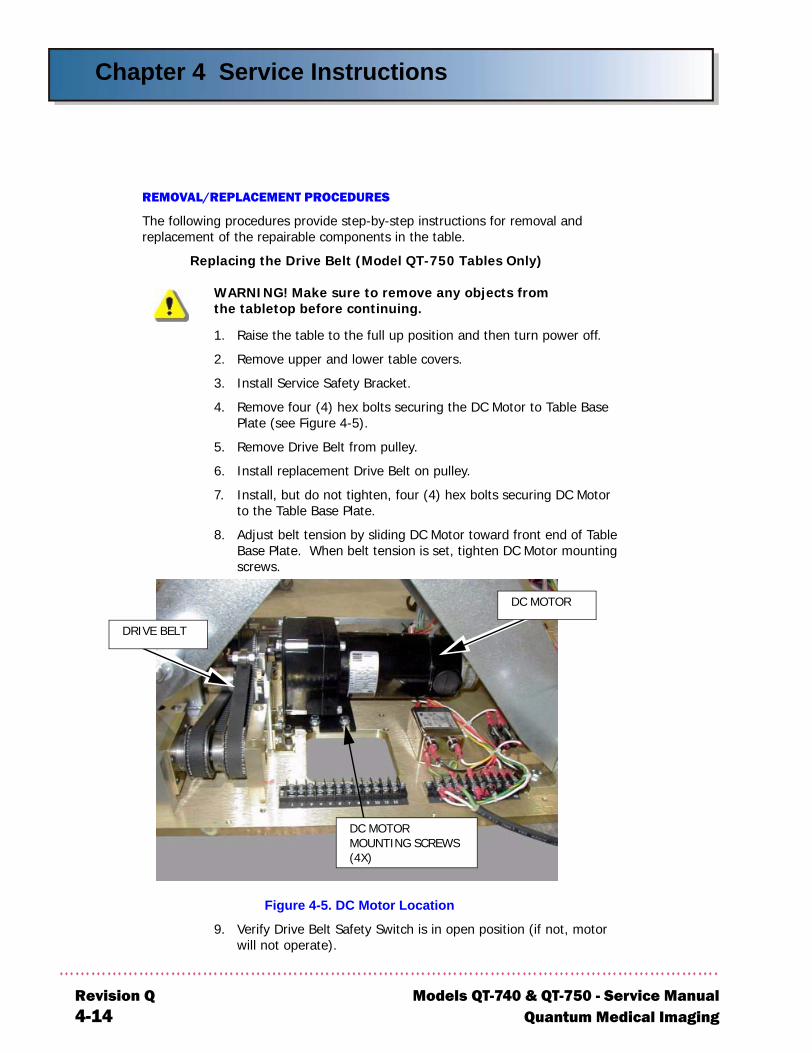
Replacing the Drive Belt (Model QT-750 Tables Only)
WARNING! Make sure to remove any objects fromthe tabletop before continuing.
1. Raise the table to the full up position and then turn power off.
2. Remove upper and lower table covers.
3. Install Service Safety Bracket.
4. Remove four (4) hex bolts securing the DC Motor to Table Base Plate (see Figure 4-5).
5. Remove Drive Belt from pulley.
6. Install replacement Drive Belt on pulley.
7. Install, but do not tighten, four (4) hex bolts securing DC Motor to the Table Base Plate.
8. Adjust belt tension by sliding DC Motor toward front end of Table Base Plate. When belt tension is set, tighten DC Motor mounting screws.
Figure 4-5. DC Motor Location
9. Verify Drive Belt Safety Switch is in open position (if not, motor will not operate).
DC MOTOR
DC MOTOR MOUNTING SCREWS (4X)
DRIVE BELT
evision Q Models QT-740 & QT-750 - Service Manual-14 Quantum Medical Imaging
Chapter 4 Service Instructions
Models QT-7Quantum M
10. Remove Safety Bracket.
11. Reinstall upper and lower table covers (refer to Chapter 2, Assembly and Installation).
12. Turn on power. Perform an operational test and check table travel and positions.
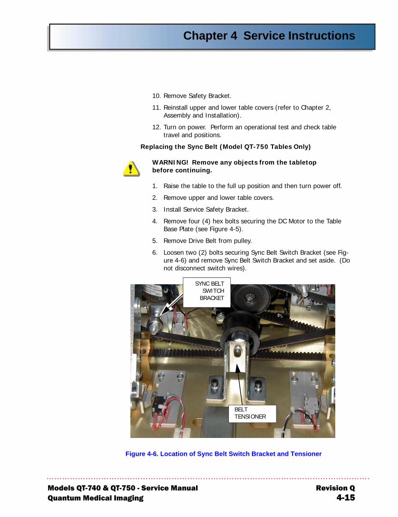
Replacing the Sync Belt (Model QT-750 Tables Only)
WARNING! Remove any objects from the tabletopbefore continuing.
1. Raise the table to the full up position and then turn power off.
2. Remove upper and lower table covers.
3. Install Service Safety Bracket.
4. Remove four (4) hex bolts securing the DC Motor to the Table Base Plate (see Figure 4-5).
5. Remove Drive Belt from pulley.
6. Loosen two (2) bolts securing Sync Belt Switch Bracket (see Fig-ure 4-6) and remove Sync Belt Switch Bracket and set aside. (Do not disconnect switch wires).
Figure 4-6. Location of Sync Belt Switch Bracket and Tensioner
BELT TENSIONER
SYNC BELTSWITCH
BRACKET
40 & QT-750 - Service Manual Revision Qedical Imaging 4-15
Chapter 4 Service Instructions
R4
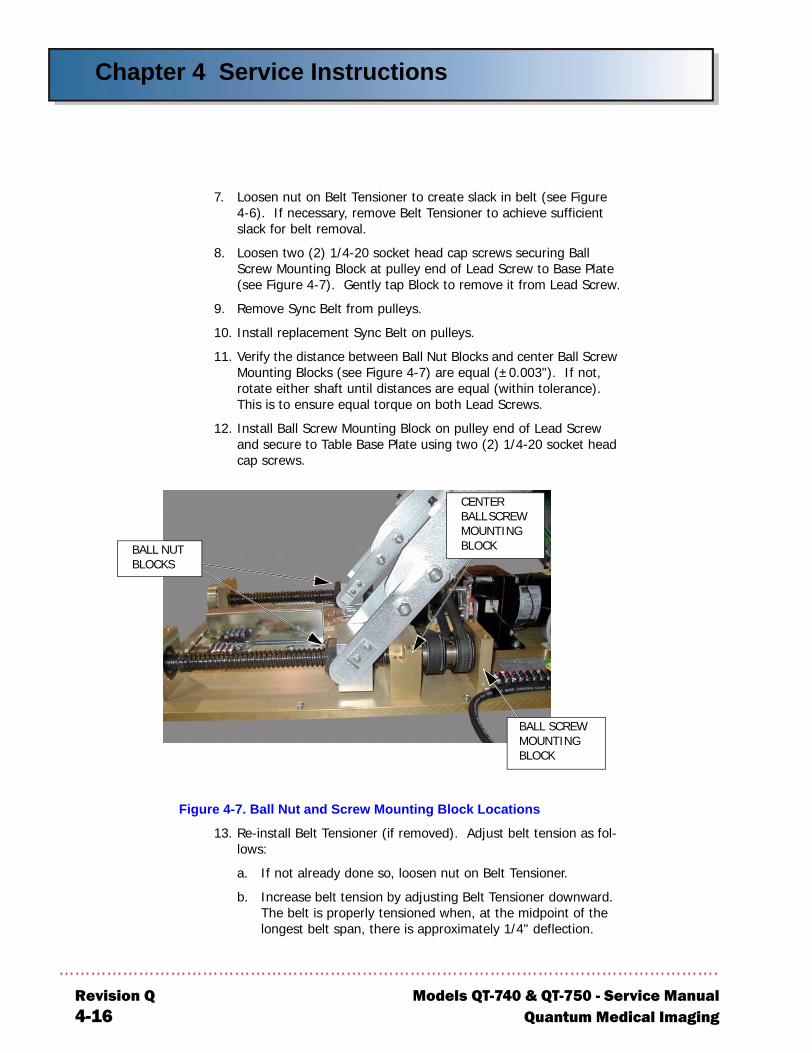
7. Loosen nut on Belt Tensioner to create slack in belt (see Figure 4-6). If necessary, remove Belt Tensioner to achieve sufficient slack for belt removal.
8. Loosen two (2) 1/4-20 socket head cap screws securing Ball Screw Mounting Block at pulley end of Lead Screw to Base Plate (see Figure 4-7). Gently tap Block to remove it from Lead Screw.
9. Remove Sync Belt from pulleys.
10. Install replacement Sync Belt on pulleys.
11. Verify the distance between Ball Nut Blocks and center Ball Screw Mounting Blocks (see Figure 4-7) are equal (±0.003"). If not, rotate either shaft until distances are equal (within tolerance). This is to ensure equal torque on both Lead Screws.
12. Install Ball Screw Mounting Block on pulley end of Lead Screw and secure to Table Base Plate using two (2) 1/4-20 socket head cap screws.
Figure 4-7. Ball Nut and Screw Mounting Block Locations
13. Re-install Belt Tensioner (if removed). Adjust belt tension as fol-lows:
a. If not already done so, loosen nut on Belt Tensioner.
b. Increase belt tension by adjusting Belt Tensioner downward. The belt is properly tensioned when, at the midpoint of the longest belt span, there is approximately 1/4" deflection.
BALL SCREW MOUNTING BLOCK
CENTER BALL SCREW MOUNTING BLOCKBALL NUT
BLOCKS
evision Q Models QT-740 & QT-750 - Service Manual-16 Quantum Medical Imaging

Chapter 4 Service Instructions
Models QT-7Quantum M
c. When belt tension is set, tighten nut on Belt Tensioner.
14. Verify Sync Belt Safety Switch is in open position (if not, motor will not operate).
15. Remove Safety Bracket.
16. Reinstall upper and lower table covers (refer to Chapter 2, Assembly and Installation).
17. Turn on power. Perform an operational test and check table travel and positions.
Replacing the DC Motor (Model QT-750 Tables Only)
1. Raise the table to the full up position and then turn power off.
2. Remove upper and lower table covers.
3. Install Service Safety Bracket.
4. Cut the two DC Motor wires connected to 6-Way Table Control Board A1 connectors A1J1-12 and A1J1-10.
5. Remove four (4) hex bolts securing the DC Motor to the Table Base Plate (see Figure 4-5).
6. Remove Drive Belt from DC Motor pulley.
7. Loosen set screw securing pulley to motor shaft and remove pul-ley from shaft. Retain pulley (and key) for re-assembly.
8. Slide pulley (with key inserted) onto shaft of replacement DC Motor.
9. Reinstall Drive Belt on DC Motor Pulley.
10. Mount DC Motor to Table Base Plate using four (4) hex bolts.
11. Be sure pulley on DC Motor is aligned with pulley on Lead Screw to within ±1/16". After adjusting pulley position, tighten set screw on DC Motor pulley.
12. Connect replacement DC Motor wires to 6-Way Table Control Board connector A1J1-12 and A1J1-10.
13. Verify Drive Belt Safety Switch is in open position (if not, motor will not operate).
14. Remove Safety Bracket.
15. Reinstall upper and lower table covers (refer to Chapter 2, Assembly and Installation).
16. Turn on power. Perform an operational test and check table travel and positions.
40 & QT-750 - Service Manual Revision Qedical Imaging 4-17
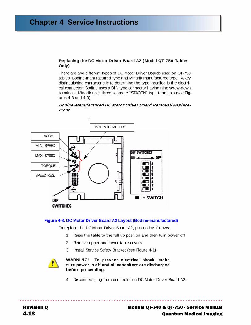
Chapter 4 Service Instructions
R4
Replacing the DC Motor Driver Board A2 (Model QT-750 Tables Only)
There are two different types of DC Motor Driver Boards used on QT-750 tables; Bodine-manufactured type and Minarik manufactured type. A key distinguishing characteristic to determine the type installed is the electri-cal connector; Bodine uses a DIN type connector having nine screw-down terminals, Minarik uses three separate "STACON" type terminals (see Fig-ures 4-8 and 4-9).
Bodine-Manufactured DC Motor Driver Board Removal/Replace-ment
.
Figure 4-8. DC Motor Driver Board A2 Layout (Bodine-manufactured)
To replace the DC Motor Driver Board A2, proceed as follows:
1. Raise the table to the full up position and then turn power off.
2. Remove upper and lower table covers.
3. Install Service Safety Bracket (see Figure 4-1).
WARNING! To prevent electrical shock, makesure power is off and all capacitors are dischargedbefore proceeding.
4. Disconnect plug from connector on DC Motor Driver Board A2.
POTENTIOMETERS
SPEED REG.
MAX. SPEED
MIN. SPEED
ACCEL.
TORQUE
evision Q Models QT-740 & QT-750 - Service Manual-18 Quantum Medical Imaging
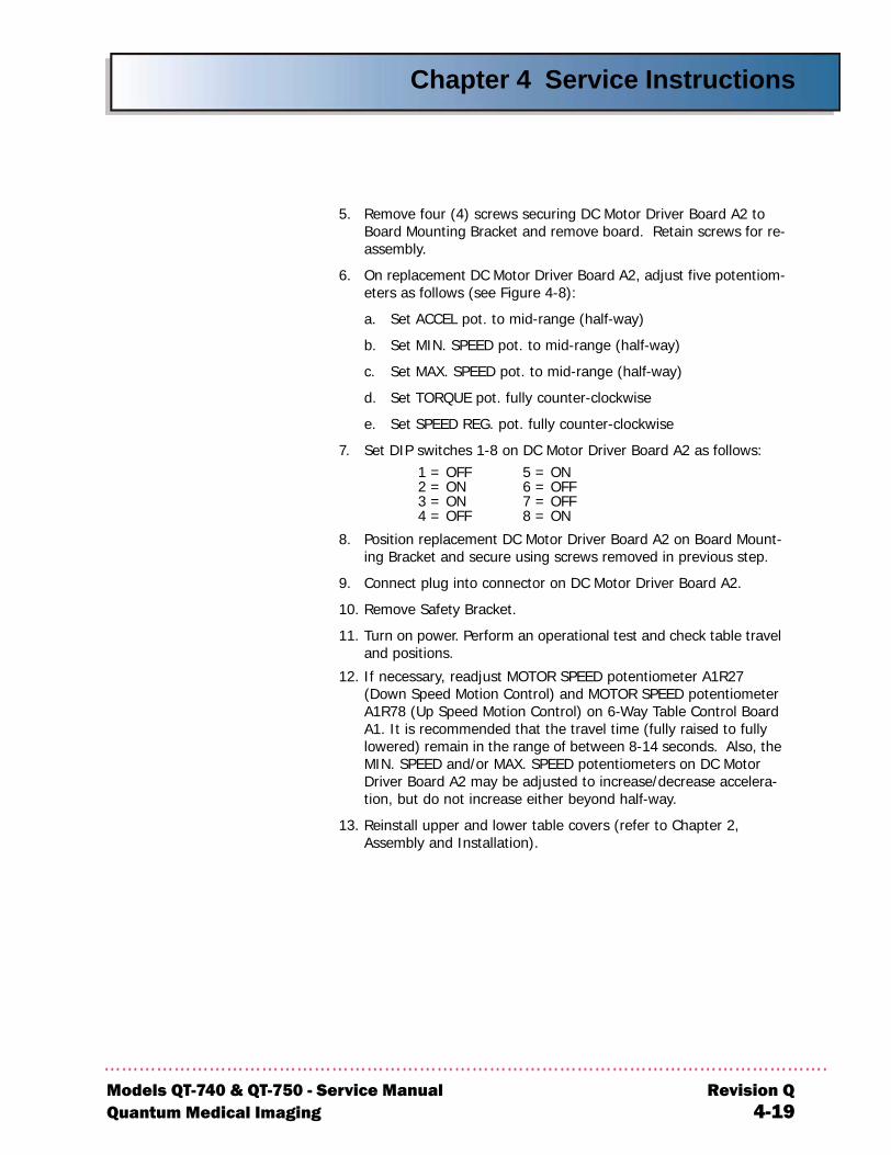
Chapter 4 Service Instructions
Models QT-Quantum M
5. Remove four (4) screws securing DC Motor Driver Board A2 to Board Mounting Bracket and remove board. Retain screws for re-assembly.
6. On replacement DC Motor Driver Board A2, adjust five potentiom-eters as follows (see Figure 4-8):
a. Set ACCEL pot. to mid-range (half-way)
b. Set MIN. SPEED pot. to mid-range (half-way)
c. Set MAX. SPEED pot. to mid-range (half-way)
d. Set TORQUE pot. fully counter-clockwise
e. Set SPEED REG. pot. fully counter-clockwise
7. Set DIP switches 1-8 on DC Motor Driver Board A2 as follows:1 = OFF 5 = ON2 = ON 6 = OFF3 = ON 7 = OFF4 = OFF 8 = ON
8. Position replacement DC Motor Driver Board A2 on Board Mount-ing Bracket and secure using screws removed in previous step.
9. Connect plug into connector on DC Motor Driver Board A2.
10. Remove Safety Bracket.
11. Turn on power. Perform an operational test and check table travel and positions.
12. If necessary, readjust MOTOR SPEED potentiometer A1R27 (Down Speed Motion Control) and MOTOR SPEED potentiometer A1R78 (Up Speed Motion Control) on 6-Way Table Control Board A1. It is recommended that the travel time (fully raised to fully lowered) remain in the range of between 8-14 seconds. Also, the MIN. SPEED and/or MAX. SPEED potentiometers on DC Motor Driver Board A2 may be adjusted to increase/decrease accelera-tion, but do not increase either beyond half-way.
13. Reinstall upper and lower table covers (refer to Chapter 2, Assembly and Installation).
740 & QT-750 - Service Manual Revision Qedical Imaging 4-19
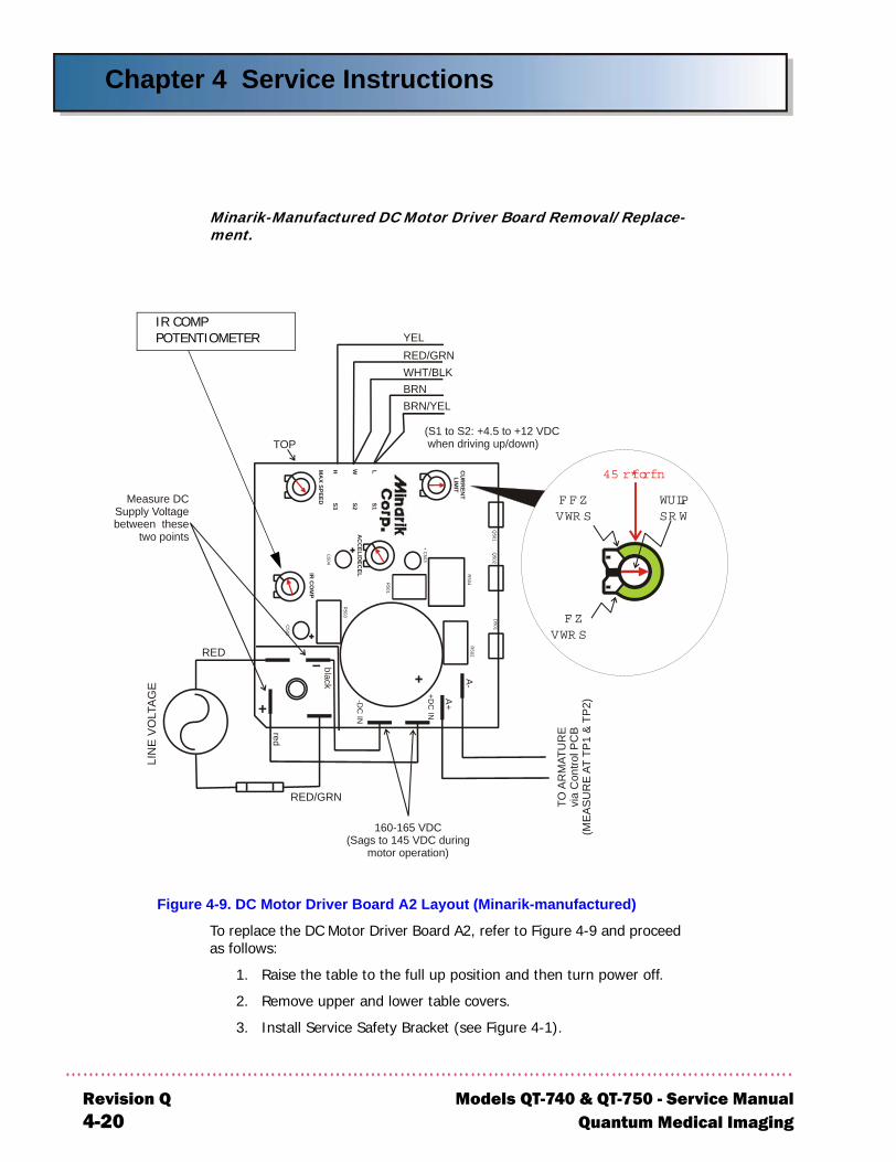
Chapter 4 Service Instructions
R4
Minarik-Manufactured DC Motor Driver Board Removal/Replace-ment.
Figure 4-9. DC Motor Driver Board A2 Layout (Minarik-manufactured)
To replace the DC Motor Driver Board A2, refer to Figure 4-9 and proceed as follows:
1. Raise the table to the full up position and then turn power off.
2. Remove upper and lower table covers.
3. Install Service Safety Bracket (see Figure 4-1).
TO A
RM
ATU
RE
via
Con
trol P
CB
(ME
AS
UR
E A
T TP
1 &
TP
2)
TOP
RED
RED/GRN
red
black
-DC
IN
LIN
E V
OL T
AG
E
AC
CEL/D
ECELIR
CO
MP
CU
RR
ENT
LIMIT
MA
X SPEED
+DC
IN
A+
R504
+ C503
R502
D501
Q502
A-
Q501
LWH
S1S2S3
R501
C504
C502
R503
Measure DCSupply Voltagebetween these
two points
160-165 VDC(Sags to 145 VDC during
motor operation)
YEL
BRN/YEL
RED/GRNWHT/BLKBRN
(S1 to S2: +4.5 to +12 VDC when driving up/down)
C CWSTO P
12 o'clock
TRIMPO T
CWSTO P
IR COMPPOTENTIOMETER
evision Q Models QT-740 & QT-750 - Service Manual-20 Quantum Medical Imaging
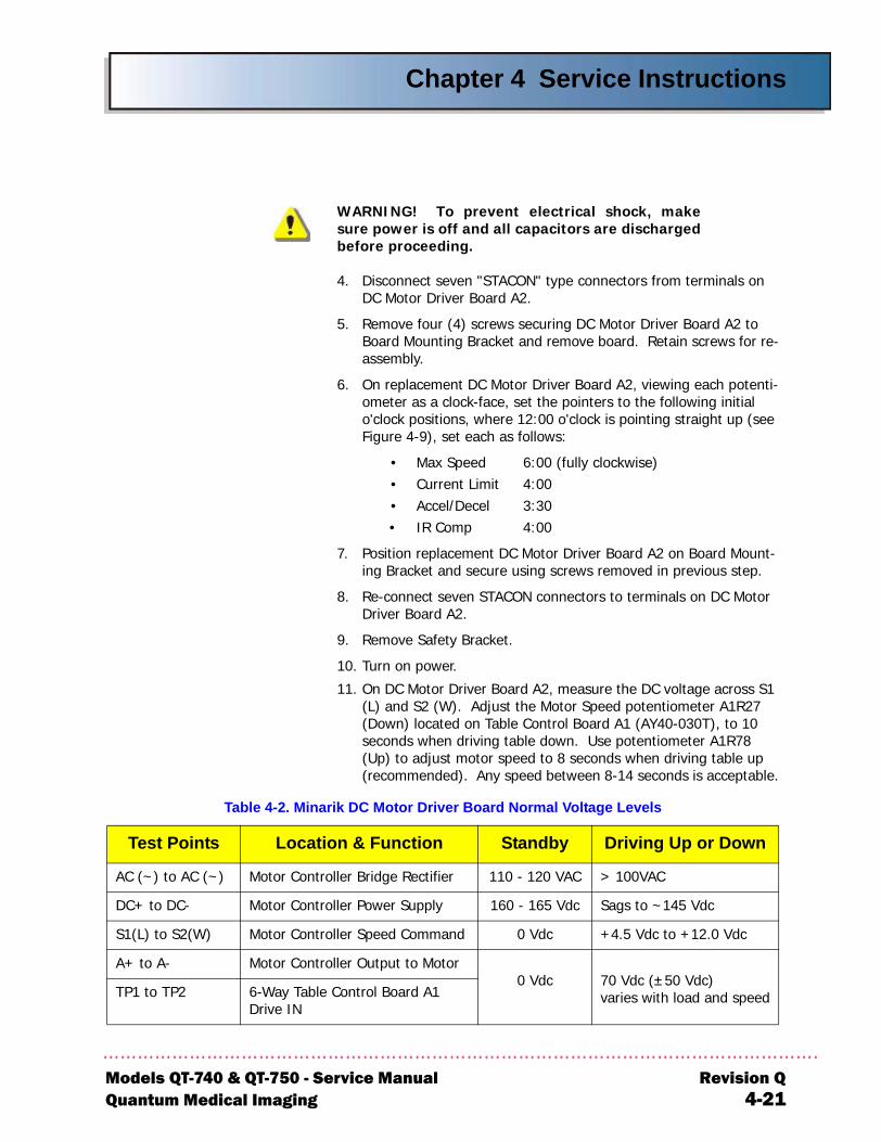
Chapter 4 Service Instructions
Models QT-7Quantum M
Test Poin
AC (~) to AC
DC+ to DC-
S1(L) to S2(W
A+ to A-
TP1 to TP2
WARNING! To prevent electrical shock, makesure power is off and all capacitors are dischargedbefore proceeding.
4. Disconnect seven "STACON" type connectors from terminals on DC Motor Driver Board A2.
5. Remove four (4) screws securing DC Motor Driver Board A2 to Board Mounting Bracket and remove board. Retain screws for re-assembly.
6. On replacement DC Motor Driver Board A2, viewing each potenti-ometer as a clock-face, set the pointers to the following initial o'clock positions, where 12:00 o'clock is pointing straight up (see Figure 4-9), set each as follows:
• Max Speed 6:00 (fully clockwise)• Current Limit 4:00• Accel/Decel 3:30 • IR Comp 4:00
7. Position replacement DC Motor Driver Board A2 on Board Mount-ing Bracket and secure using screws removed in previous step.
8. Re-connect seven STACON connectors to terminals on DC Motor Driver Board A2.
9. Remove Safety Bracket.
10. Turn on power.
11. On DC Motor Driver Board A2, measure the DC voltage across S1 (L) and S2 (W). Adjust the Motor Speed potentiometer A1R27 (Down) located on Table Control Board A1 (AY40-030T), to 10 seconds when driving table down. Use potentiometer A1R78 (Up) to adjust motor speed to 8 seconds when driving table up (recommended). Any speed between 8-14 seconds is acceptable.
Table 4-2. Minarik DC Motor Driver Board Normal Voltage Levels
ts Location & Function Standby Driving Up or Down
(~) Motor Controller Bridge Rectifier 110 - 120 VAC > 100VAC
Motor Controller Power Supply 160 - 165 Vdc Sags to ~145 Vdc
) Motor Controller Speed Command 0 Vdc +4.5 Vdc to +12.0 Vdc
Motor Controller Output to Motor0 Vdc 70 Vdc (±50 Vdc)
varies with load and speed6-Way Table Control Board A1 Drive IN
40 & QT-750 - Service Manual Revision Qedical Imaging 4-21
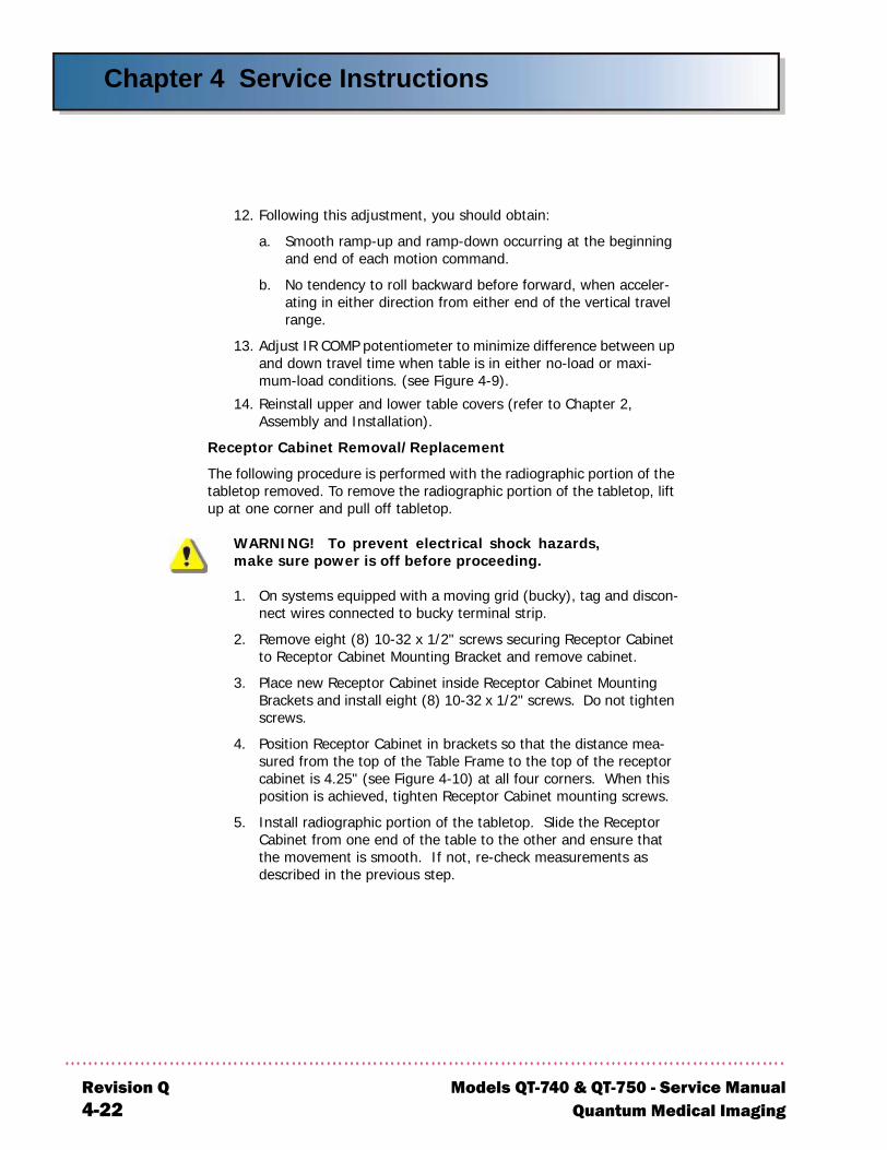
Chapter 4 Service Instructions
R4
12. Following this adjustment, you should obtain:
a. Smooth ramp-up and ramp-down occurring at the beginning and end of each motion command.
b. No tendency to roll backward before forward, when acceler-ating in either direction from either end of the vertical travel range.
13. Adjust IR COMP potentiometer to minimize difference between up and down travel time when table is in either no-load or maxi-mum-load conditions. (see Figure 4-9).
14. Reinstall upper and lower table covers (refer to Chapter 2, Assembly and Installation).
Receptor Cabinet Removal/Replacement
The following procedure is performed with the radiographic portion of the tabletop removed. To remove the radiographic portion of the tabletop, lift up at one corner and pull off tabletop.
WARNING! To prevent electrical shock hazards,make sure power is off before proceeding.
1. On systems equipped with a moving grid (bucky), tag and discon-nect wires connected to bucky terminal strip.
2. Remove eight (8) 10-32 x 1/2" screws securing Receptor Cabinet to Receptor Cabinet Mounting Bracket and remove cabinet.
3. Place new Receptor Cabinet inside Receptor Cabinet Mounting Brackets and install eight (8) 10-32 x 1/2" screws. Do not tighten screws.
4. Position Receptor Cabinet in brackets so that the distance mea-sured from the top of the Table Frame to the top of the receptor cabinet is 4.25" (see Figure 4-10) at all four corners. When this position is achieved, tighten Receptor Cabinet mounting screws.
5. Install radiographic portion of the tabletop. Slide the Receptor Cabinet from one end of the table to the other and ensure that the movement is smooth. If not, re-check measurements as described in the previous step.
evision Q Models QT-740 & QT-750 - Service Manual-22 Quantum Medical Imaging
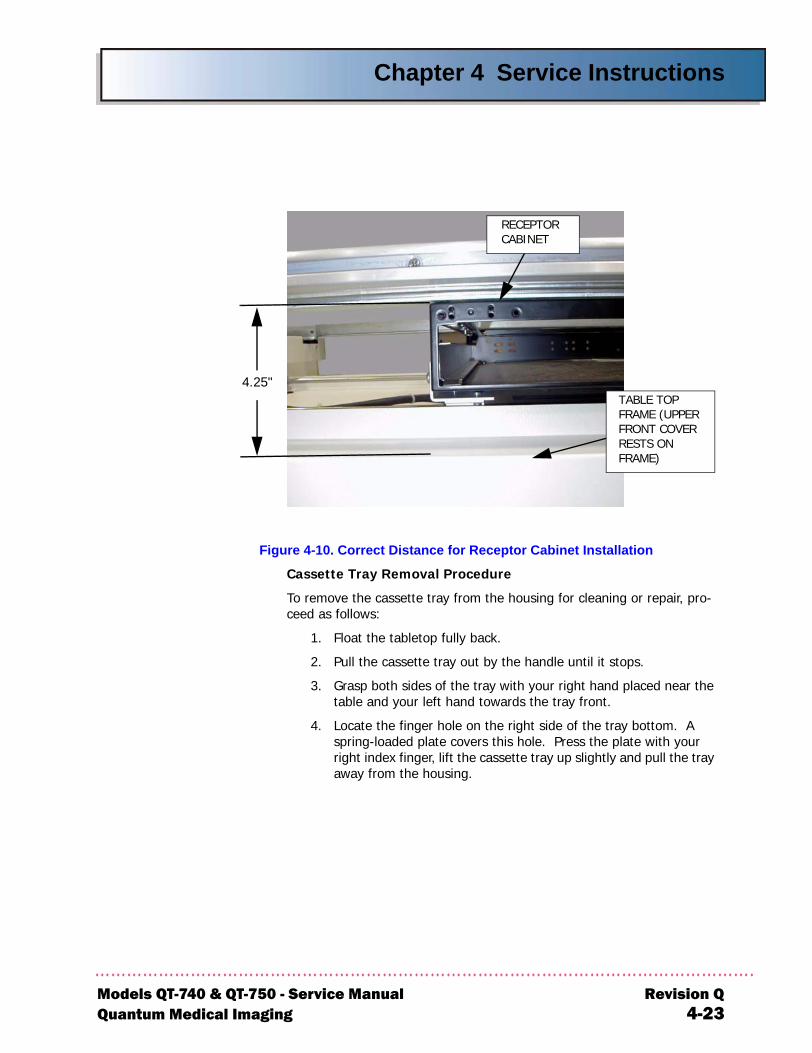
Chapter 4 Service Instructions
Models QT-7Quantum M
Figure 4-10. Correct Distance for Receptor Cabinet Installation
Cassette Tray Removal Procedure
To remove the cassette tray from the housing for cleaning or repair, pro-ceed as follows:
1. Float the tabletop fully back.
2. Pull the cassette tray out by the handle until it stops.
3. Grasp both sides of the tray with your right hand placed near the table and your left hand towards the tray front.
4. Locate the finger hole on the right side of the tray bottom. A spring-loaded plate covers this hole. Press the plate with your right index finger, lift the cassette tray up slightly and pull the tray away from the housing.
4.25"
RECEPTOR CABINET
TABLE TOP FRAME (UPPER FRONT COVER RESTS ON FRAME)
40 & QT-750 - Service Manual Revision Qedical Imaging 4-23
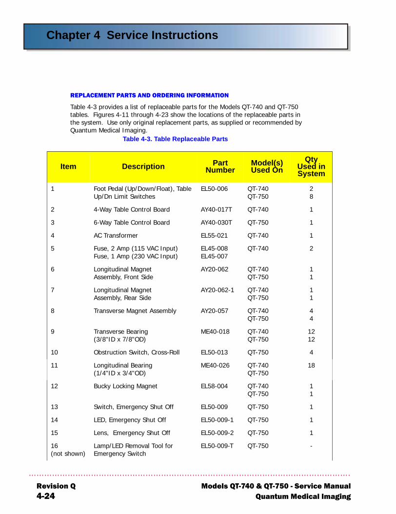
Chapter 4 Service Instructions
R4
ty d in tem
28
1
1
1
2
11
11
44
22
4
8
11
1
1
1
-
REPLACEMENT PARTS AND ORDERING INFORMATION
Table 4-3 provides a list of replaceable parts for the Models QT-740 and QT-750 tables. Figures 4-11 through 4-23 show the locations of the replaceable parts in the system. Use only original replacement parts, as supplied or recommended by Quantum Medical Imaging.
Table 4-3. Table Replaceable Parts
Item Description Part Number
Model(s) Used On
QUseSys
1 Foot Pedal (Up/Down/Float), Table Up/Dn Limit Switches
EL50-006 QT-740QT-750
2 4-Way Table Control Board AY40-017T QT-740
3 6-Way Table Control Board AY40-030T QT-750
4 AC Transformer EL55-021 QT-740
5 Fuse, 2 Amp (115 VAC Input)Fuse, 1 Amp (230 VAC Input)
EL45-008EL45-007
QT-740
6 Longitudinal MagnetAssembly, Front Side
AY20-062 QT-740QT-750
7 Longitudinal MagnetAssembly, Rear Side
AY20-062-1 QT-740QT-750
8 Transverse Magnet Assembly AY20-057 QT-740QT-750
9 Transverse Bearing(3/8"ID x 7/8"OD)
ME40-018 QT-740QT-750
11
10 Obstruction Switch, Cross-Roll EL50-013 QT-750
11 Longitudinal Bearing(1/4"ID x 3/4"OD)
ME40-026 QT-740QT-750
1
12 Bucky Locking Magnet EL58-004 QT-740QT-750
13 Switch, Emergency Shut Off EL50-009 QT-750
14 LED, Emergency Shut Off EL50-009-1 QT-750
15 Lens, Emergency Shut Off EL50-009-2 QT-750
16(not shown)
Lamp/LED Removal Tool forEmergency Switch
EL50-009-T QT-750
evision Q Models QT-740 & QT-750 - Service Manual-24 Quantum Medical Imaging
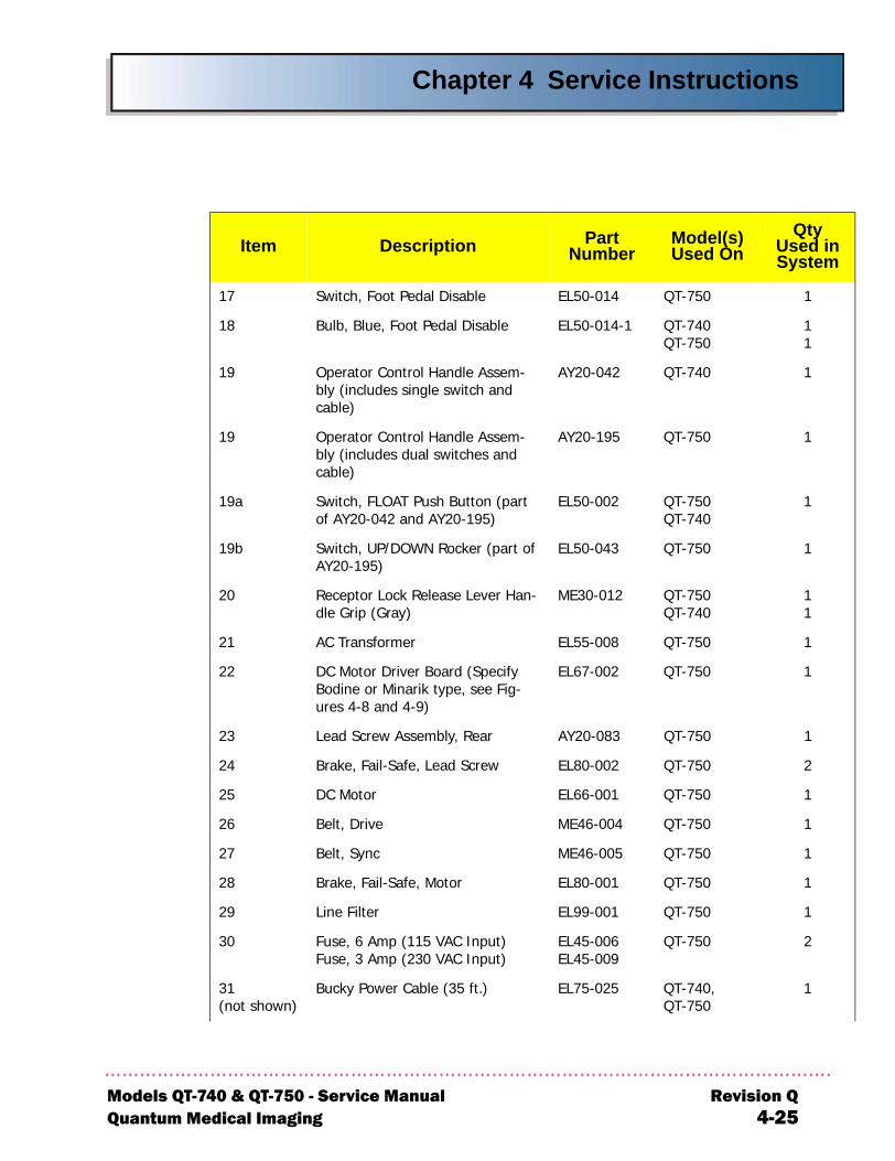
Chapter 4 Service Instructions
Models QT-Quantum M
1
11
1
1
1
1
11
1
1
1
2
1
1
1
1
1
2
1
ty d in tem
17 Switch, Foot Pedal Disable EL50-014 QT-750
18 Bulb, Blue, Foot Pedal Disable EL50-014-1 QT-740QT-750
19 Operator Control Handle Assem-bly (includes single switch and cable)
AY20-042 QT-740
19 Operator Control Handle Assem-bly (includes dual switches and cable)
AY20-195 QT-750
19a Switch, FLOAT Push Button (part of AY20-042 and AY20-195)
EL50-002 QT-750QT-740
19b Switch, UP/DOWN Rocker (part of AY20-195)
EL50-043 QT-750
20 Receptor Lock Release Lever Han-dle Grip (Gray)
ME30-012 QT-750QT-740
21 AC Transformer EL55-008 QT-750
22 DC Motor Driver Board (Specify Bodine or Minarik type, see Fig-ures 4-8 and 4-9)
EL67-002 QT-750
23 Lead Screw Assembly, Rear AY20-083 QT-750
24 Brake, Fail-Safe, Lead Screw EL80-002 QT-750
25 DC Motor EL66-001 QT-750
26 Belt, Drive ME46-004 QT-750
27 Belt, Sync ME46-005 QT-750
28 Brake, Fail-Safe, Motor EL80-001 QT-750
29 Line Filter EL99-001 QT-750
30 Fuse, 6 Amp (115 VAC Input)Fuse, 3 Amp (230 VAC Input)
EL45-006EL45-009
QT-750
31(not shown)
Bucky Power Cable (35 ft.) EL75-025 QT-740,QT-750
Item Description Part Number
Model(s) Used On
QUseSys
740 & QT-750 - Service Manual Revision Qedical Imaging 4-25
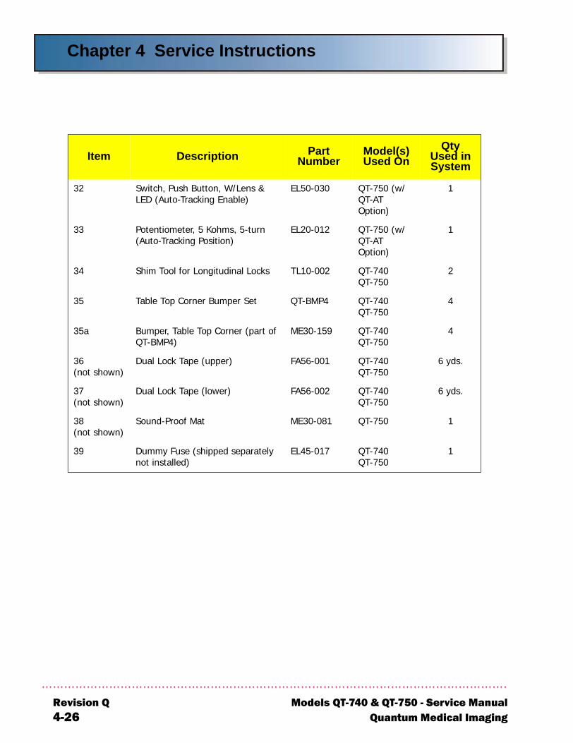
Chapter 4 Service Instructions
R4
1
1
2
4
4
ds.
ds.
1
1
ty d in tem
32 Switch, Push Button, W/Lens & LED (Auto-Tracking Enable)
EL50-030 QT-750 (w/ QT-AT Option)
33 Potentiometer, 5 Kohms, 5-turn (Auto-Tracking Position)
EL20-012 QT-750 (w/ QT-AT Option)
34 Shim Tool for Longitudinal Locks TL10-002 QT-740QT-750
35 Table Top Corner Bumper Set QT-BMP4 QT-740QT-750
35a Bumper, Table Top Corner (part of QT-BMP4)
ME30-159 QT-740QT-750
36(not shown)
Dual Lock Tape (upper) FA56-001 QT-740QT-750
6 y
37(not shown)
Dual Lock Tape (lower) FA56-002 QT-740QT-750
6 y
38(not shown)
Sound-Proof Mat ME30-081 QT-750
39 Dummy Fuse (shipped separately not installed)
EL45-017 QT-740QT-750
Item Description Part Number
Model(s) Used On
QUseSys
evision Q Models QT-740 & QT-750 - Service Manual-26 Quantum Medical Imaging
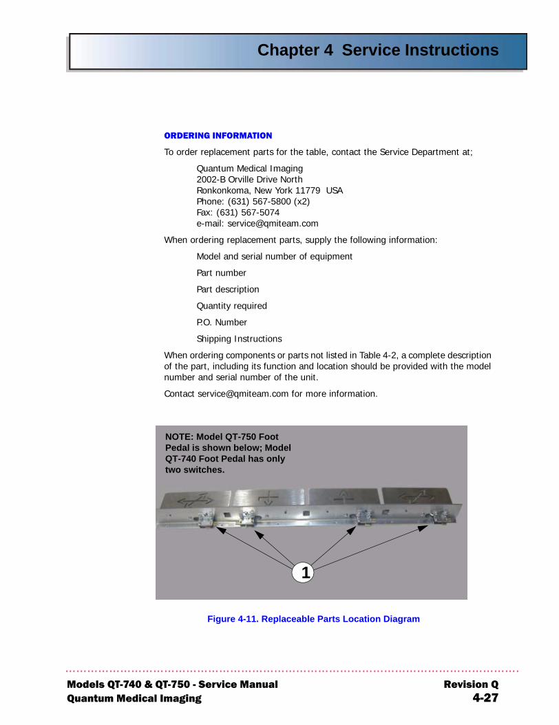
Chapter 4 Service Instructions
Models QT-Quantum M
ORDERING INFORMATION
To order replacement parts for the table, contact the Service Department at;
Quantum Medical Imaging2002-B Orville Drive NorthRonkonkoma, New York 11779 USAPhone: (631) 567-5800 (x2)Fax: (631) 567-5074e-mail: [email protected]
When ordering replacement parts, supply the following information:
Model and serial number of equipment
Part number
Part description
Quantity required
P.O. Number
Shipping Instructions
When ordering components or parts not listed in Table 4-2, a complete description of the part, including its function and location should be provided with the model number and serial number of the unit.
Contact [email protected] for more information.
Figure 4-11. Replaceable Parts Location Diagram
1
NOTE: Model QT-750 Foot Pedal is shown below; Model QT-740 Foot Pedal has only two switches.
740 & QT-750 - Service Manual Revision Qedical Imaging 4-27
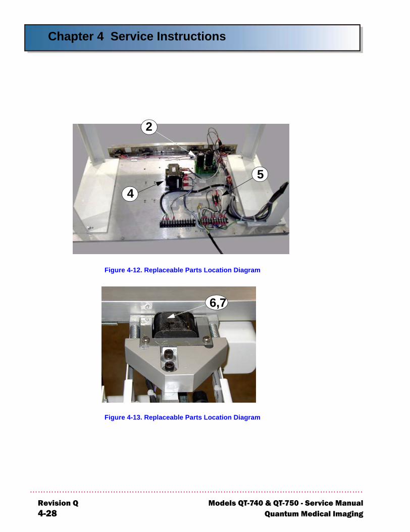
Chapter 4 Service Instructions
R4
Figure 4-12. Replaceable Parts Location Diagram
Figure 4-13. Replaceable Parts Location Diagram
2
54
6,7
evision Q Models QT-740 & QT-750 - Service Manual-28 Quantum Medical Imaging
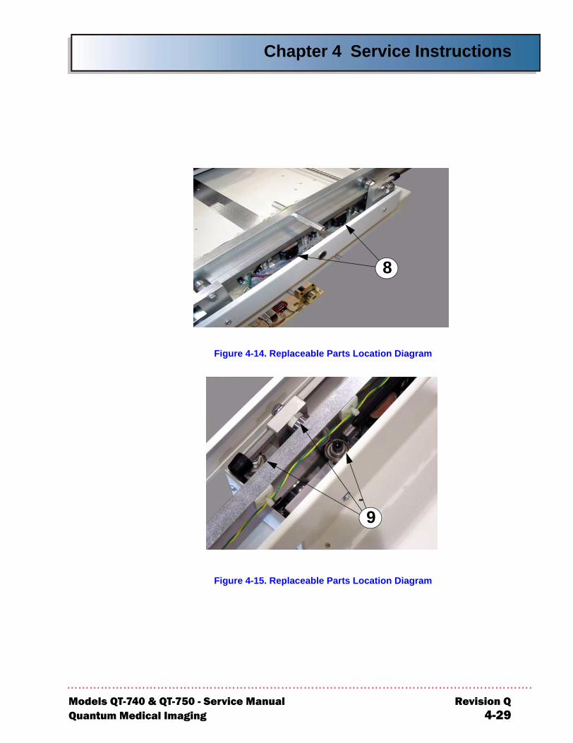
Chapter 4 Service Instructions
Models QT-7Quantum M
Figure 4-14. Replaceable Parts Location Diagram
Figure 4-15. Replaceable Parts Location Diagram
8
9
40 & QT-750 - Service Manual Revision Qedical Imaging 4-29

Chapter 4 Service Instructions
R4
Figure 4-16. Replaceable Parts Location Diagram
Figure 4-17. Replaceable Parts Location Diagram
10
11
12
evision Q Models QT-740 & QT-750 - Service Manual-30 Quantum Medical Imaging
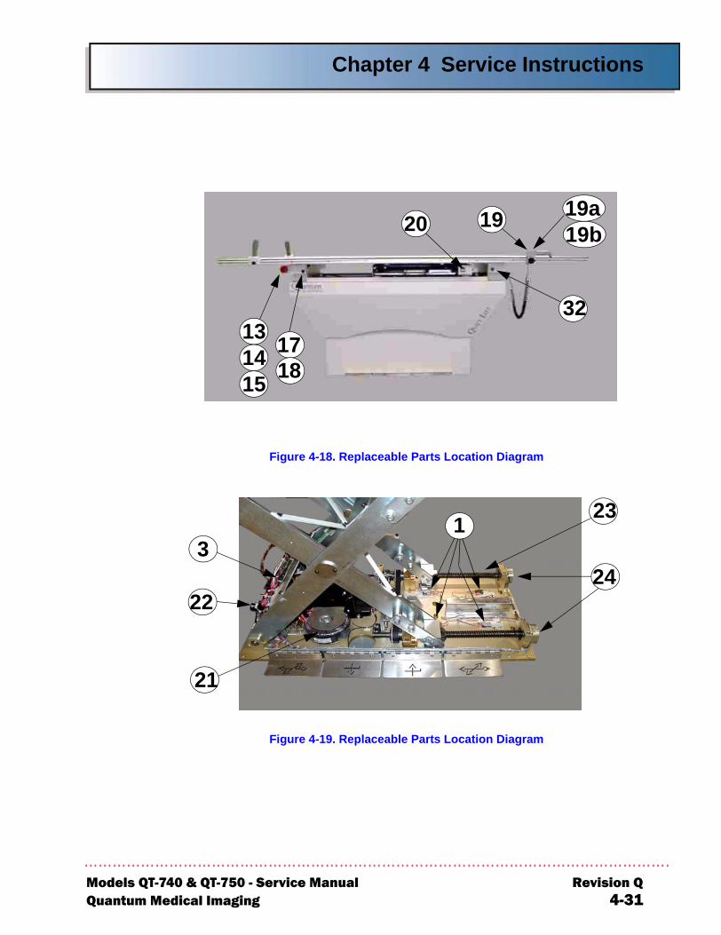
Chapter 4 Service Instructions
Models QT-7Quantum M
Figure 4-18. Replaceable Parts Location Diagram
Figure 4-19. Replaceable Parts Location Diagram
19
1718
20
131415
19a19b
32
3
21
2224
123
40 & QT-750 - Service Manual Revision Qedical Imaging 4-31
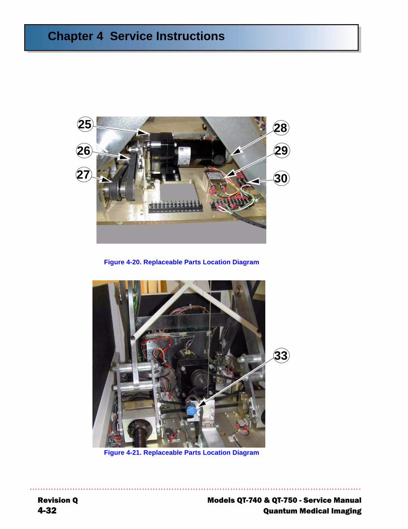
Chapter 4 Service Instructions
R4
Figure 4-20. Replaceable Parts Location Diagram
Figure 4-21. Replaceable Parts Location Diagram
30
29
25 28
26
27
33
evision Q Models QT-740 & QT-750 - Service Manual-32 Quantum Medical Imaging
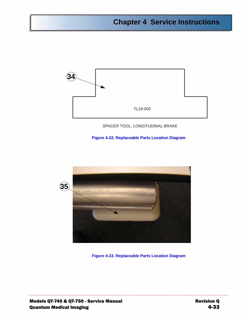
Chapter 4 Service Instructions
Models QT-7Quantum M
Figure 4-22. Replaceable Parts Location Diagram
Figure 4-23. Replaceable Parts Location Diagram
SPACER TOOL, LONGITUDINAL BRAKE
TL10-002
34
35
40 & QT-750 - Service Manual Revision Qedical Imaging 4-33
Chapter 4 Service Instructions
Models QT-7Quantum M
THIS PAGE INTENTIONALLY LEFT BLANK
40 & QT-750 - Service Manual Revision Qedical Imaging 4-34

Chapter
5-1
DIAGRAMS
5

5-2
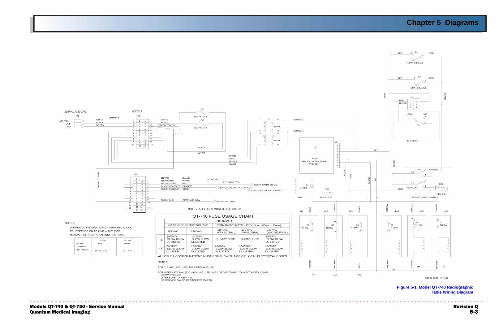
Chapter 5 Diagrams
ModeQuan
Figure 5-1. Model QT-740 RadiographicTable Wiring Diagram
1212
55
1110
9
1112
10
11109
8
67
78
6
9
1211109
8
67
78
6
2
45
3
4
23
11 2
3454
23
11
10 10
33
7
98
10
89
7
456 5
6
4
7
89
7
1098
56
4 56
4
23
112
12
23
1
12
1
211 1
2
2
2
1 1
2 2
4 ab
12
49
1
17
1319
15
3 3
1,3
1,34
2
2
23
1
12
3
1
12
2
1
32
115VAC
TB2
GNDLINE
NEUTRAL
TB1
SEE NOTE 2
SEE NOTE 2
F2
F1
DS2D1
PED DIS
TH SWTH SW
BUCKY SW
LM
EXPOSURE BUCKY CONTACT
BUCKY START SIGNALEXPOSURE BUCKY CONTACT
BUCKY GROUND
115VAC RTN
TH SWS6
BM
1N4005 S5
LM TMSC50-003T REV. K
TMTM TM
TH SWS8S7 TH SW
TH SWS9
S10
PEDAL DIS
S11
T1
S4
S3
FLOAT (PEDAL)
J1
S2
FLOAT (PEDAL)
S1
GR
EEN
/YEL
LOW
WHITE
ORANGEGREEN
BLACK
RED
GREEN/YELLOWBUCKY GND
115VAC RTNBUCKY START
BUCKY CONTACTBUCKY CONTACT
115VAC
GREENBLACKWHITE
115VAC/230VACIN
NOTE 1
BLACK
WHITE
GREEN/YELLOWBLACKWHITE
M6M1 M2 M3
- + PEDAL DISABLE SWITCH
M4
RED
M5
BLACK
TABLE CONTROL BOARD
WHITEWHITE
BLACKBROWNBLUE
AY40-017T
4-WAY
A1
ORANGE
ORANGE
18VAC
18VAC
1
8
BLAC
K
RE
D
67
5
34
2
BLAC
K
RED
RED
J1
BLA
CK
BROWN
E-Z GLIDE
COM N/O
RED
BLACKRED
P1
N/O COM
N/O COM
NOTE 3
PU
RP
LEBL
UE
BRO
WN
GR
EEN
BR
OW
N
BR
OW
N
RE
D
YELL
OW
OR
ANG
E
BLAC
K
YELL
OW
OR
ANG
E
LINE INPUT
230 VAC115 VAC
CORD CONNECTED (With Plug) PERMANENT INSTALLATION (Hard Wired to Mains)
2A/250VSLOW BLOWUL LISTED
ALL OTHER CONFIGURATIONS MUST COMPLY WITH NEC OR LOCAL ELECTRICAL CODES
2A/250VSLOW BLOWUL LISTED
1A/250VSLOW BLOWUL LISTED 1A/250VSLOW BLOWUL LISTED
115 VAC(W/NEUTRAL)
DUMMY FUSE
230 VAC(W/NEUTRAL)
230 VAC(W/O NEUTRAL)
DUMMY FUSE1A/250VSLOW BLOWUL LISTED
QT-740 FUSE USAGE CHART
2A/250VSLOW BLOWUL LISTED
1A/250VSLOW BLOWUL LISTED
1A/250VSLOW BLOWUL LISTED
F1
F2
NOTE 1:
230 VACINPUT
TB1: 6-10TB1: 5-6, 9-10
115 VACINPUT
JUMPER CONFIGURATION OF TERMINAL BLOCKTB1 DEPENDS ON AC LINE INPUT. (SEEMANUAL FOR ADDITIONAL INSTRUCTIONS).
INSTALLJUMPERBETWEEN:
NOTE 2: ALL FUSES MUST BE U.L. LISTED.
NOTE 3:
FOR 115 VAC LINE, USE LINE CORD AY51-170.
FOR INTERNATIONAL (230 VAC) LINE, USE LINE CORD EL75-038; CONNECT AS FOLLOWS: BROWN TO LINE LIGHT BLUE TO NEUTRAL GREEN/YELLOW TO PROTECTIVE EARTH
ls QT-740 & QT-750 - Service Manual Revision Qtum Medical Imaging 5-3
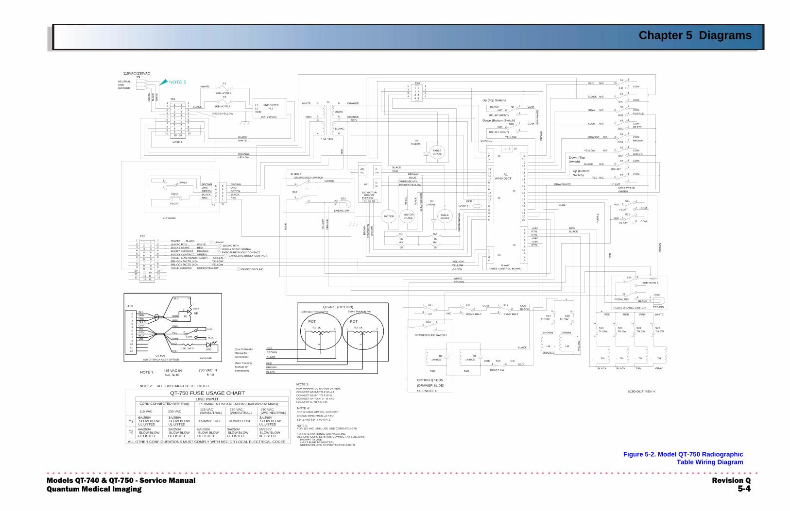
Chapter 5 Diagrams
ModeQuan
Figure 5-2. Model QT-750 RadiographicTable Wiring Diagram
+24V
GREEN/YELLOWTABLE GROUND
BUCKY STARTBUCKY CONTACTBUCKY CONTACTTABLE READY(GND=READY)PBL CONTACTS (NO)PBL CONTACTS (NO)
115VAC RTN
GREEN
YELLOWYELLOW
GREEN
ORANGEREDWHITE
BLACK
YEL
LOW
SEE NOTE 4
(DRAWER SLIDE)
OPTION QT-DDS
COM N/CRED
SC50-001T REV. V
ORANGE
BLACK BLACK
- -
TAN GRAY
- -
TABLE CONTROL BOARD
DRAWER SLIDE SWITCH
N/C
COM
GREEN
BROWNWHITE
YELLOWYELLOW
34
12
-
-GREENBROWN
BLACKCOM
+
RED
PEDAL DISABLE SWITCH
RED+
PINK WHITE
BLACK
J4
6-WAY
37
J3
105
29
RTN
SEE NOTE 4
RED
BR
OW
N
EMERGENCY SWITCH
BLACKGREEN
RED
BLACK115VAC
E Z GLIDE
REDBLACKGREEN
BLU
E
ORGBROWNBROWN
ORG
NOTE 1:
PURPLE
YELLOWORANGE
WHITEBLACK
115VAC/230VACIN
GREEN/YELLOW
BLACK
WHITE
10A, 250VAC
GND
RED
LINE FILTERL1L2 FL1
WHITE
BRO
WN
AY40-030T
8
MOTORBRAKE
BRO
WN
YELL
OW
OR
ANG
E
YELL
OW
RE
D/G
REE
N
MOTOR
DRIVERDC MOTOR
S1EL67-002
WH
ITE
S3S2
GR
EE
N/B
RO
WNTABLE
BRAKE45
BLAC
K
GR
EEN
/BR
OW
N
7NOTE 3:
23
6
RED
1516
14
WHITE/BLACK
BROWN
BROWN/YELLOWA2GREEN
ACAC
I1I2
A-A+
REDBLACK
RED
BLUE12
91
10
1113
BRAKETABLE
23
1
ORANGE
6
+24V
RTN46
+24V
18
RTN
1020
REDBLACK
8
919
18
J1
J2
717
16
BLUE
PU
RP
LE
N/0COM
GREEN
N/0COM
Switch)Up (Bottom
Down (TopSwitch)2
4
515
14
A1
313
12
GRAY/WHITE
1 2 J6
J5 111
YELLOW
GRAY/WHITE
RED N/C
BLACK N/C
COM
N/0YELLOW
N/0ORANGE
COM
GREENCOM
BROWNCOM
Up (Top Switch)
Down (Bottom Switch)
BLACK
110VAC
20VAC
REDORANGE
ORANGE
N/0RED
N/C
GR
AY/W
HIT
E
N/CCOM
COMCOMN/0GRAY
BLUE N/0WHITECOM
PURPLE
N/0BLACKCOM
COM
R4R3115VAC115VAC RTN
EXPOSURE BUCKY CONTACTEXPOSURE BUCKY CONTACTBUCKY START SIGNAL
BUCKY GROUND
S15
BUCKY SWBM2
1N4005D2
BM1
D11N4005 TM TM TM TM
S24
OT
S21
DRIVE BELT
S22
35 35
DS2
LM LM
SYNC BELT
S23
TH SWS17
TH SWS18
TH SWS19 S20
TH SWS24TH SW
S25TH SW
PEDAL DIS
PED DIS
S14
TB2
FLOAT
SW14
J1P1
S16
SW13
LINEGROUND
NEUTRALF1
SEE NOTE 2:
SEE NOTE 2:
TB1F2
35
R1
EMERG SW
DS1
35
R2
1N4005D3
4-62-4305
1N4005D2
FLOAT
S11
FLOAT
S12
UP LMT
DN LMT
S9
OS4
S7
OS3
S6
UP LMT (RDNT)
DN LMT (RDNT)
TB3
T1
S10
S8
OS2
S5
OS1
S4
S3
/DN
S2
/UP
S1
11
10
12
9
1112
1011
5
789 8
67 6
345 4
23 2
9
1112
12
101011
5
78
89
667
34
45
223
1 2
12
3
23
12
3
1
1 1
23
1
2 2
1 1
2 2
1 1
2 2
4 ab
3
12
10 10
1
44
1
2211
33
34
3
12
551
2
33
10
66 778
109 88 9
9 9
7 87
4
65 5
5 65
34
434
21 1
12
212
4
23
1
X1X2
23
2
1
3
1
2
2
3
1
3
2
2
1
3
1
3
34
2
8
67
5
1
444
2
32
32 3
111
2
2
12
3
3
12
2
1
3
1
3
2
1
3
1
3
1
GR
EEN
BLA
CK
WH
ITE
NOTE 5
COM
QT-MATAUTO TRACK ASSY OPTION
BLU
VIO
ORN
YEL
BRN
GRN
RED
BLK
N.C.
AY51-098
N.O.
5KR1
1.2K, 2W 5
J101
LED
POT
YEL
BLUGRN
VIO
12
1011
78
56
2
BRN
SHLDRED
BLK
ORN94
23
1
2
1
3
13
Servo Tracking Pot
QT-ACT (OPTION)
POT
BROWNManual for
Manual forconnection)
connection)
(See Tracking
BLACK
BROWN
RED
BLACK
(See Collimator RED
1 3 1
Collimator Tracking Pot
POT
3R1 1K R2 5K
2 2
NOTE 5:FOR 115 VAC LINE, USE LINE CORD AY51-170.
FOR INTERNATIONAL (230 VAC) LINE,USE LINE CORD EL75-038; CONNECT AS FOLLOWS: BROWN TO LINE LIGHT BLUE TO NEUTRAL GREEN/YELLOW TO PROTECTIVE EARTH
LINE INPUT
230 VAC115 VAC
CORD CONNECTED (With Plug) PERMANENT INSTALLATION (Hard Wired to Mains)
6A/250VSLOW BLOWUL LISTED
ALL OTHER CONFIGURATIONS MUST COMPLY WITH NEC OR LOCAL ELECTRICAL CODES
6A/250VSLOW BLOWUL LISTED
3A/250VSLOW BLOWUL LISTED
3A/250VSLOW BLOWUL LISTED
115 VAC(W/NEUTRAL)
DUMMY FUSE
230 VAC(W/NEUTRAL)
230 VAC(W/O NEUTRAL)
DUMMY FUSE3A/250VSLOW BLOWUL LISTED
QT-750 FUSE USAGE CHART
6A/250VSLOW BLOWUL LISTED
3A/250VSLOW BLOWUL LISTED
3A/250VSLOW BLOWUL LISTED
F1
F2
ls QT-740 & QT-750 - Service Manual Revision Qtum Medical Imaging 5-4
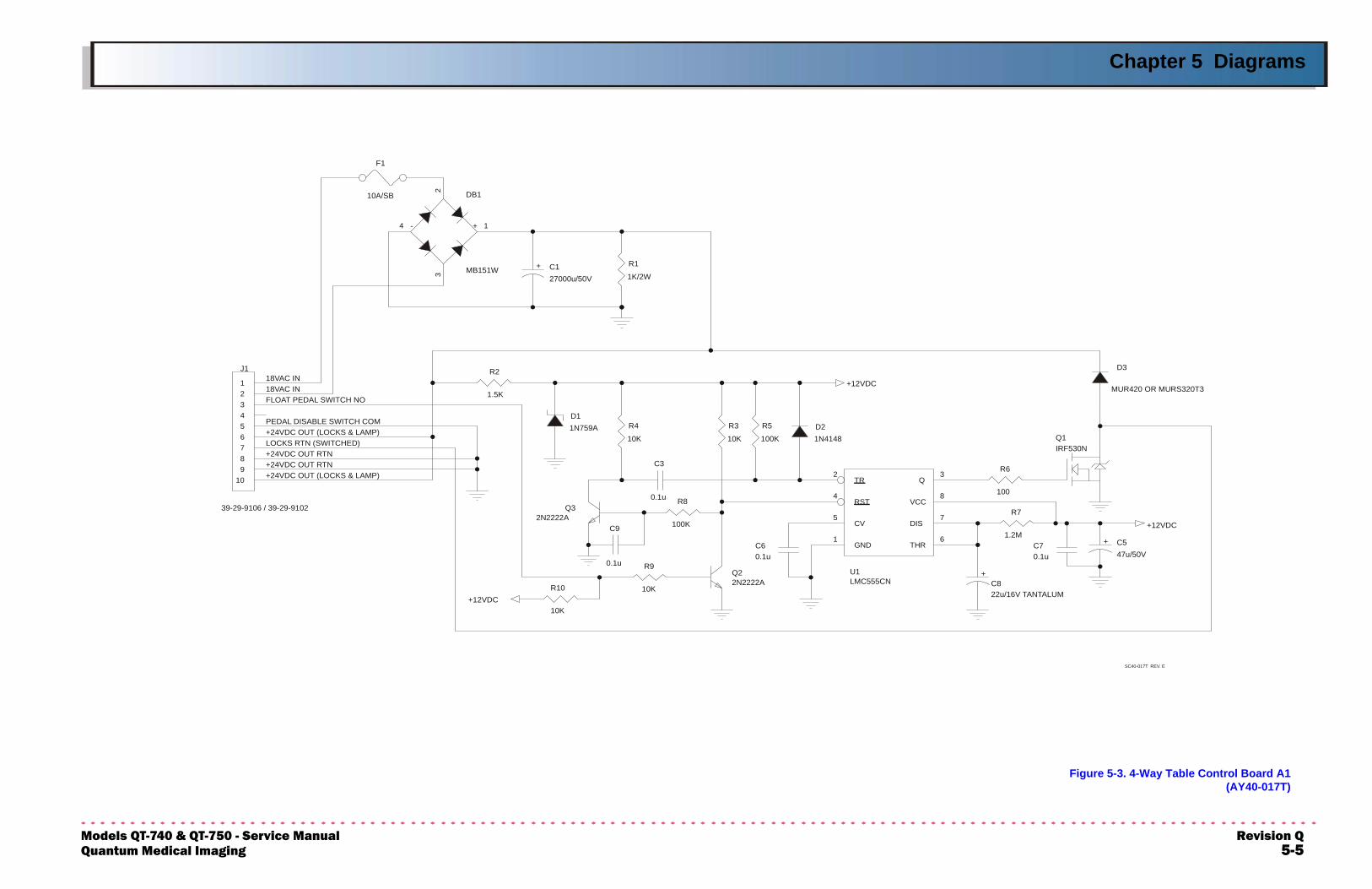
Chapter 5 Diagrams
ModeQuan
Figure 5-3. 4-Way Table Control Board A1 (AY40-017T)
R5
100K
D11N759A
Q22N2222A
C70.1u
R10
10K
C9
0.1u
C3
0.1u
D21N4148
U1LMC555CN
GND1
TR2
RST4
CV5
Q3
VCC8
DIS7
THR6
R3
10K
C822u/16V TANTALUM
+
J1
39-29-9106 / 39-29-9102
123456789
10
R1
1K/2WC127000u/50V
+
DB1
MB151W
2
1
3
4 - +
R8
100K
R9
10K
Q32N2222A
Q1IRF530N
R6
100
R7
1.2MC547u/50V
+
F1
10A/SB
R2
1.5K
D3
MUR420 OR MURS320T3
R4
10K
C60.1u
+12VDC
+12VDC
+12VDC
LOCKS RTN (SWITCHED)+24VDC OUT RTN
+24VDC OUT (LOCKS & LAMP)
FLOAT PEDAL SWITCH NO
PEDAL DISABLE SWITCH COM
18VAC IN18VAC IN
+24VDC OUT RTN+24VDC OUT (LOCKS & LAMP)
SC40-017T REV. E
ls QT-740 & QT-750 - Service Manual Revision Qtum Medical Imaging 5-5
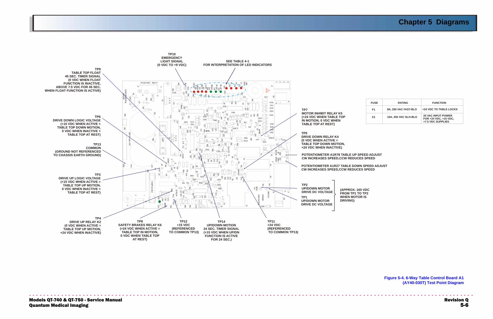
Chapter 5 Diagrams
ModeQuan
Figure 5-4. 6-Way Table Control Board A1(AY40-030T) Test Point Diagram
R23
R25
R73
C20
C3
D11D13
D14
D15
D20
D27
D28
D29
D30
D35
D39
D41
D45
D46
D49
D50
D54
D55
D60
D63
R1
R12
R17
R19
R2
R3
R35
R40
R47
R50
R55
R56
R64
R8
65
65
D70
R76
R26
C35
C36
R80
.Q6
.R73
D34
D23
PC40-030T REV F
TP10EMERGENCY
LIGHT SIGNAL(0 VDC TO +9 VDC)
TP9TABLE TOP FLOAT
45 SEC. TIMER SIGNAL(0 VDC WHEN FLOAT
FUNCTION IS INACTIVE,ABOVE 7.5 VDC FOR 45 SEC.
WHEN FLOAT FUNCTION IS ACTIVE)
TP14UP/DOWN MOTION
24 SEC. TIMER SIGNAL(+15 VDC WHEN UP/DNFUNCTION IS ACTIVE
FOR 24 SEC.)
TP1UP/DOWN MOTORDRIVE DC VOLTAGE
TP2UP/DOWN MOTORDRIVE DC VOLTAGE (APPROX. 160 VDC
FROM TP1 TO TP2WHEN MOTOR ISDRIVING)
TP13COMMON
(GROUND NOT REFERENCEDTO CHASSIS EARTH GROUND)
TP3DRIVE UP LOGIC VOLTAGE
(+15 VDC WHEN ACTIVE =TABLE TOP UP MOTION,
0 VDC WHEN INACTIVE =TABLE TOP AT REST)
TP6DRIVE DOWN LOGIC VOLTAGE
(+15 VDC WHEN ACTIVE =TABLE TOP DOWN MOTION,
0 VDC WHEN INACTIVE =TABLE TOP AT REST)
TP4DRIVE UP RELAY K2
(0 VDC WHEN ACTIVE =TABLE TOP UP MOTION,
+24 VDC WHEN INACTIVE)
TP11+24 VDC(REFERENCED TO COMMON TP13)
TP5DRIVE DOWN RELAY K4(0 VDC WHEN ACTIVE =TABLE TOP DOWN MOTION,+24 VDC WHEN INACTIVE)
TP12+15 VDC
(REFERENCED TO COMMON TP13)
TP8SAFETY BRAKES RELAY K6(+24 VDC WHEN ACTIVE =
TABLE TOP IN MOTION,0 VDC WHEN TABLE TOP
AT REST)
TP7MOTOR INHIBIT RELAY K5(+24 VDC WHEN TABLE TOPIN MOTION, 0 VDC WHENTABLE TOP AT REST)
20 VAC INPUT POWERFOR +24 VDC, +15 VDC,+7.5 VDC SUPPLIES
10A, 250 VAC SLO-BLOF2
+24 VDC TO TABLE LOCKS8A, 250 VAC FAST-BLOF1
FUSE RATING FUNCTION
SEE TABLE 4-1FOR INTERPRETATION OF SLED INDICATOR
POTENTIOMETER A1R78 TABLE UP SPEED ADJUSTCW INCREASES SPEED,CCW REDUCES SPEED
POTENTIOMETER A1R27 TABLE DOWN SPEED ADJUSTCW INCREASES SPEED,CCW REDUCES SPEED
ls QT-740 & QT-750 - Service Manual Revision Qtum Medical Imaging 5-6
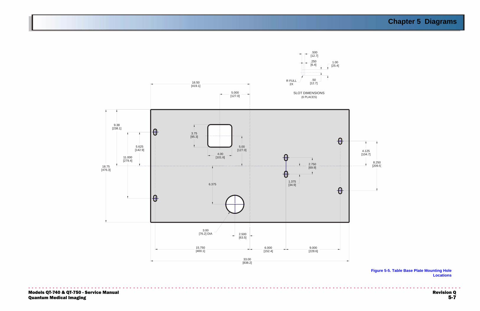
Chapter 5 Diagrams
ModeQuan
Figure 5-5. Table Base Plate Mounting HoleLocations
33.00[838.2]
.500[12.7]
.250[6.4]
.50[12.7]
1.00[25.4]
R FULL2X
4.125[104.7]
8.250[209.5]
3.75[95.3]
16.50[419.1]
5.625[142.9]
11.000[279.4]
2.750[69.9]
1.375[34.9]
2.500[63.5]
6.375
3.00[76.2] DIA
6.000[152.4]
9.000[228.6]
15.750[400.1]
4.00[101.6]
5.000[127.0]
5.00[127.0]
9.38[238.1]
SLOT DIMENSIONS(6 PLACES)
18.75[476.3]
ls QT-740 & QT-750 - Service Manual Revision Qtum Medical Imaging 5-7
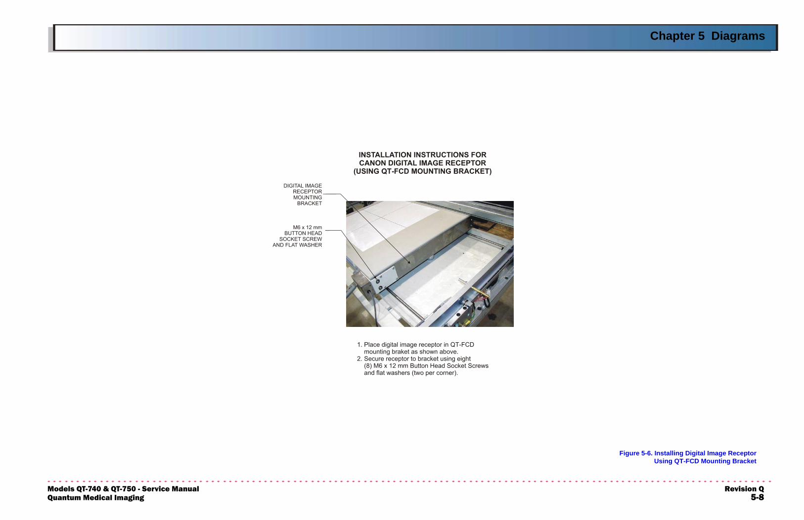
Chapter 5 Diagrams
ModeQuan
Figure 5-6. Installing Digital Image ReceptorUsing QT-FCD Mounting Bracket
ls QT-740 & QT-750 - Service Manual Revision Qtum Medical Imaging 5-8
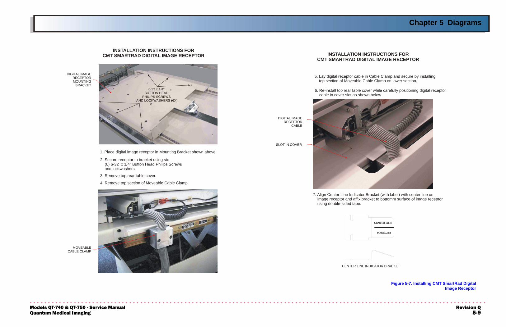
Chapter 5 Diagrams
ModeQuan
Figure 5-7. Installing CMT SmartRad DigitalImage Receptor
6-32 x 1/4"BUTTON HEAD
PHILIPS SCREWS AND LOCKWASHERS (6X)
DIGITAL IMAGERECEPTORMOUNTING
BRACKET
MOVEABLECABLE CLAMP
INSTALLATION INSTRUCTIONS FORCMT SMARTRAD DIGITAL IMAGE RECEPTOR
1. Place digital image receptor in Mounting Bracket shown above.
2. Secure receptor to bracket using six (6) 6-32 x 1/4" Button Head Philips Screws and lockwashers.
3. Remove top rear table cover.
4. Remove top section of Moveable Cable Clamp.
7. Align Center Line Indicator Bracket (with label) with center line on image receptor and affix bracket to bottomm surface of image receptor using double-sided tape.
CENTER LINE INDICATOR BRACKET
DIGITAL IMAGERECEPTOR
CABLE
SLOT IN COVER
INSTALLATION INSTRUCTIONS FORCMT SMARTRAD DIGITAL IMAGE RECEPTOR
5. Lay digital receptor cable in Cable Clamp and secure by installing top section of Moveable Cable Clamp on lower section.
6. Re-install top rear table cover while carefully positioning digital receptor cable in cover slot as shown below .
ls QT-740 & QT-750 - Service Manual Revision Qtum Medical Imaging 5-9