Embed Size (px)
Citation preview
Installation Instructions:
DC6-48-60-0-8C-EV
INSTALL INSTRUCTIONS DC6-48-60-0-8C-EV
www.raycap.com

INSTALL INSTRUCTIONS DC6-48-60-0-8C-EV
www.raycap.com
©Raycap • All rights reserved
(320-1318) Rev.A
Page 1 of 18
Contents
Section Description Page
1 Copyright 2
1.1 Disclaimer 2
1.2 Warnings 2
2 Introduction 3
3 OVP Package Contents 3
3.1 Prerequisites 3
3.2 Tools 3
4 Mounting the Bracket - Options 4
5 Ground Cable Installation 4
6 Pre-wiring Preparation Procedure 5
8 Removing and Securing Touch Guards 6
9 Installing DC Trunk 7
10 Installing DC Jumpers 9
11 Installing Alarm Cable 10
12 Installing Touch Guards 11
13 Securing Fiber Wires, DC Cable to Mounting Base 12
14 Securing Dome Cover and Dome Base Clamp 13
Addendum 1: 4-AWG Cable Trunk 14
DC6-48-60-0-8C-EV INSTALL INSTRUCTIONS
www.raycap.com
©Raycap • All rights reserved
(320-1318) Rev.A
Page 2 of 18
1.0 Copyright © Raycap, Inc. 2018 - All Rights Reserved
1.1 Disclaimer
above. This documentation is intended for the use of Raycap customers only for the purposes of the agreement
form or means without the prior written permission of Raycap. The documentation has been prepared to be
used by professional and properly trained personnel, and the customer assumes full responsibility when using it.
Raycap welcomes customer comments as part of the process of continuous development and improvement of
the documentation.
Raycap has made all reasonable efforts to ensure that the instructions contained in this document are adequate
and free of material errors and omissions. Raycap will, if deemed necessary, explain issues which may not be
covered by this document.
The contents of this document are subject to revision without notice due to continued progress in methodology,
design and manufacturing. Raycap shall have no liability for any damage of any kind resulting from the use of
this document.
1.2 WarningsPlease read this manual prior to use to become familiar with the product’s numerous features and operating
procedures. To maintain the maximum degree of safety, follow the sequences as outlined.
Before using the product, read all instructions and cautionary markings on the product and on any equipment
connected to the product.
CAUTION:
Unless otherwise noted, product usage that is not recommended or sold by the product manufacturer can
Do not operate the product if it has been damaged in any way. Return damaged products to their
manufacturer for repair or replacement.
which stresses the cables at the fastening point.
WARNING:
Do not stare into the laser beam or view it directly with optical instruments even if the interface has been
disabled.
Secure the cables so that they are not supporting their own weight. Place excess cable out of the way in a
neatly coiled loop. Placing fasteners on a loop helps cables maintain their shape.
Disconnect or disable the DC power source to the product prior to beginning its installation. Ensure that the
DC power source to the product remains de-energized until the completion of the installation and after all
Electrostatic sensitive devices. ESD mitigative procedures, such as wearing wriststraps are to be used
during installation and maintenance.
(208) 777-1166, (800) 890-2569 or www.raycap.com
Thank you for choosing quality products from Raycap.

INSTALL INSTRUCTIONS DC6-48-60-0-8C-EV
www.raycap.com
©Raycap • All rights reserved
(320-1318) Rev.A
Page 3 of 18
2.0 Introduction
In a split Radio Base Station (RBS) architecture the typical RBS consists of a Base Band Unit (BBU) and Remote Radio Heads (RRH) connected by cabling. Power to the RRH is provided through copper cables traveling from the DC power plant to the top of the tower or roof top. This creates a conductive path, making the active equipment at the top and the base of the site vulnerable to damage by direct lightning strikes. Protection systems installed in front of the PDU (DC power plant) and the RRH must be able to withstand direct lightning currents in order to protect the sensitive equipment. Raycap’s RRH solutions featuring Strikesorb® SPD technology
management solutions.
3.0 OVP Package Contents
1 eachDome CoverDome BaseDome Base ClampSealing O-RingMetal Mounting Base (already attached to Dome Base)Pre-terminated LanyardCarabiner for LanyardSheet of 21 blank labels for installer useOval Gasket: Power (for 2 trunks) 8AWGOval Gasket: Power (for 2 trunks) 6AWGOval Gasket: Power (for 2 trunks) 4AWG
10-24 Hex Nut, Silicon Bronze, Qty 85Lockwasher #10, External Tooth, Silicon Bronze, Qty 85
Ground Lug - #2, Dual ¼" Stud, 1" P, Long, w/o window
3.1 Prerequisites
This Document describes how to install the DC6-48-60-0-8C-EV on-site and how to mount, and connect it to external interfaces.
industry professionals who have attended training on the proper handling, installation and cleaning
mobile operator. Installers are required to read this installation guide thoroughly prior to installation of the Raycap RRH protection equipment.
3.2 Tools & Supplies
1/2" nut driver (oval gasket)
7/16" Nut Driver to install ground lug
Torque wrench/tool
2 each 17mm open end wrench (one for each side on mounting bracket for mounting to 2"-4" pole)
Recommended Banding Tools:
Site Pro: Strapping- part # WRL100
Site Pro: Clamps- part # BU254-25
Site Pro: Heavy Banding Tool- part # T001

DC6-48-60-0-8C-EV INSTALL INSTRUCTIONS
www.raycap.com
©Raycap • All rights reserved
(320-1318) Rev.A
Page 4 of 18
ProcedureMounting the Bracket
Dome unit is to be mounted at least 10' above ground.
4.1 Option 1: Pole Mount Using Pre-installed existing hardware, mount bracket to 2" to 4" diameter pole.
4.2 Option 2: MonopoleRemove supplied nut and bolt poleHardware from Bracket. Use 1" stainlesssteel bands (not supplied) through slots on bracket to mount to monopole.
4.3 Option 3: UnistrutUsing hardware from mounting bracket,mount to Unistrut (not supplied).
Ground Cable Installation
5.1 Attach #2 ground cable to #2, Dual 1/4" Stud, 1" P, Long, w/o window, ground lug on frame as shown. Ground lug can be mounted to either grounding location. Using the included lock washers, tighten nuts with a 7/16" nutdriver.
Note: Glands removed for clarity.
Torque: 65 in-lbs
5.2 Ground cable installation complete.
INSTALL INSTRUCTIONS DC6-48-60-0-8C-EV
www.raycap.com
©Raycap • All rights reserved
(320-1318) Rev.A
Page 5 of 18
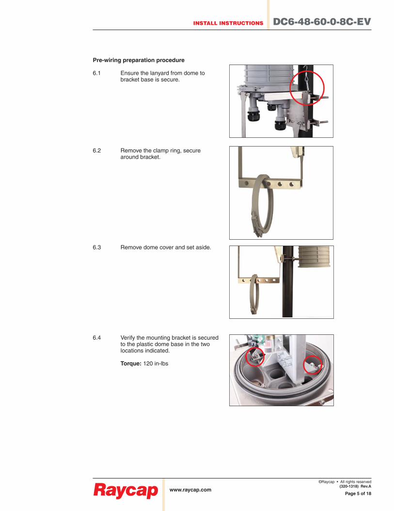
Pre-wiring preparation procedure
6.1 Ensure the lanyard from dome to bracket base is secure.
6.2 Remove the clamp ring, secure around bracket.
6.3 Remove dome cover and set aside.
6.4 Verify the mounting bracket is secured to the plastic dome base in the two locations indicated.
Torque: 120 in-lbs
DC6-48-60-0-8C-EV INSTALL INSTRUCTIONS
www.raycap.com
©Raycap • All rights reserved
(320-1318) Rev.A
Page 6 of 18
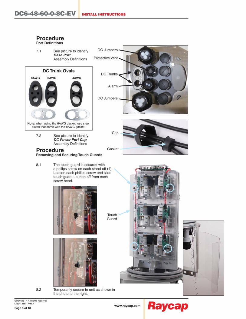
DC Trunk Ovals
8AWG 6AWG 4AWG
Note: when using the 6AWG gasket, use steel plates that come with the 8AWG gasket.
Procedure
7.1 See picture to identify Base Port
7.2 See picture to identify
DC Jumpers
Protective Vent
DC Trunks
Alarm
DC Jumpers
Cap
GasketProcedure Removing and Securing Touch Guards
8.1 The touch guard is secured with a philips screw on each stand-off (4). Loosen each philips screw and slide touch guard up then off from each screw head.
8.2 Temporarily secure to unit as shown in the photo to the right.
Touch Guard
INSTALL INSTRUCTIONS DC6-48-60-0-8C-EV
www.raycap.com
©Raycap • All rights reserved
(320-1318) Rev.A
Page 7 of 18
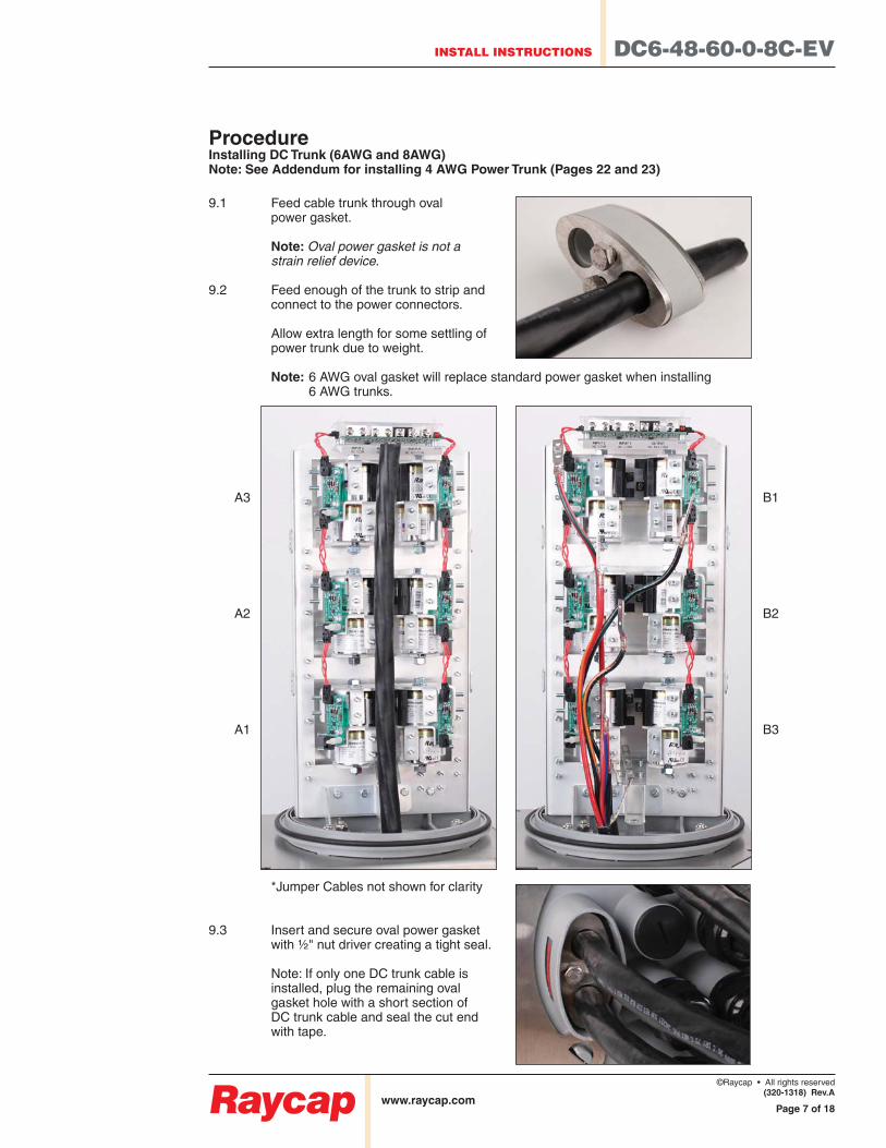
Procedure Installing DC Trunk (6AWG and 8AWG)Note: See Addendum for installing 4 AWG Power Trunk (Pages 22 and 23)
power gasket.
Note: Oval power gasket is not a strain relief device.
connect to the power connectors.
Allow extra length for some settling of power trunk due to weight.
Note: 6 AWG oval gasket will replace standard power gasket when installing 6 AWG trunks.
A3
A2
A1
B1
B2
B3
*Jumper Cables not shown for clarity
9.3 Insert and secure oval power gasket with ½" nut driver creating a tight seal.
Note: If only one DC trunk cable is installed, plug the remaining oval gasket hole with a short section of DC trunk cable and seal the cut end with tape.
DC6-48-60-0-8C-EV INSTALL INSTRUCTIONS
www.raycap.com
©Raycap • All rights reserved
(320-1318) Rev.A
Page 8 of 18
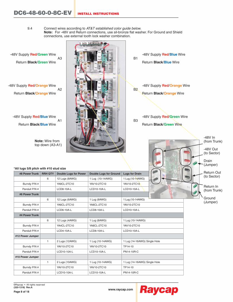
*All lugs 5/8 pitch with #10 stud size
#8 Power Trunk RRH QTY Double Lugs for Power Double Lugs for Ground Lugs for Drain
6 12 Lugs (8AWG) 1 Lug (10-14AWG) 1 Lug (10-14AWG)
Burndy P/N # YA8CL-2TC10 YAV10-2TC10 YAV10-2TC10
Panduit P/N # LCD8-10A-L LCD10-10A-L LCD10-10A-L
#6 Power Trunk
6 12 Lugs (6AWG) 1 Lug (8AWG) 1 Lug (10-14AWG)
Burndy P/N # YA6CL-2TC10 YA8CL-2TC10 YAV10-2TC10
Panduit P/N # LCD6-10A-L LCD8-10A-L LCD10-10A-L
#4 Power Trunk
6 12 Lugs (4AWG) 1 Lug (8AWG) 1 Lug (10-14AWG)
Burndy P/N # YA4CL-2TC10 YA8CL-2TC10 YAV10-2TC10
Panduit P/N # LCD4-10A-L LCD8-10A-L LCD10-10A-L
#12 Power Jumper
1 2 Lugs (12AWG) 1 Lug (10-14AWG) 1 Lug (14-16AWG) Single Hole
Burndy P/N # YAV10-2TC10 YAV10-2TC10 TP14-10
Panduit P/N # LCD10-10A-L LCD10-10A-L PN14-10R-C
#10 Power Jumper
1 2 Lugs (10AWG) 1 Lug (10-14AWG) 1 Lug (14-16AWG) Single Hole
Burndy P/N # YAV10-2TC10 YAV10-2TC10 TP14-10
Panduit P/N # LCD10-10A-L LCD10-10A-L PN14-10R-C
9.4 Connect wires according to AT&T established color guide below. Note: connections, use external tooth lock washer combination.
Note: Wire from top down (A3-A1)
-48V Supply Red/Green WireA3
Return Black/Green Wire
-48V Supply Red/Orange WireA2
Return Black/Orange Wire
-48V Supply Red/Blue WireA1
Return Black/Blue Wire
-48V Supply Red/Blue WireB1 Return Black/Blue Wire
-48V Supply Red/Orange WireB2 Return Black/Orange Wire
-48V Supply Red/Green WireB3 Return Black/Green Wire
-48V In(from Trunk)
-48V Out(to Sector)
Drain (Jumper)
Return Out(to Sector)
Return In(from Trunk)
Ground(Jumper)
INSTALL INSTRUCTIONS DC6-48-60-0-8C-EV
www.raycap.com
©Raycap • All rights reserved
(320-1318) Rev.A
Page 9 of 18
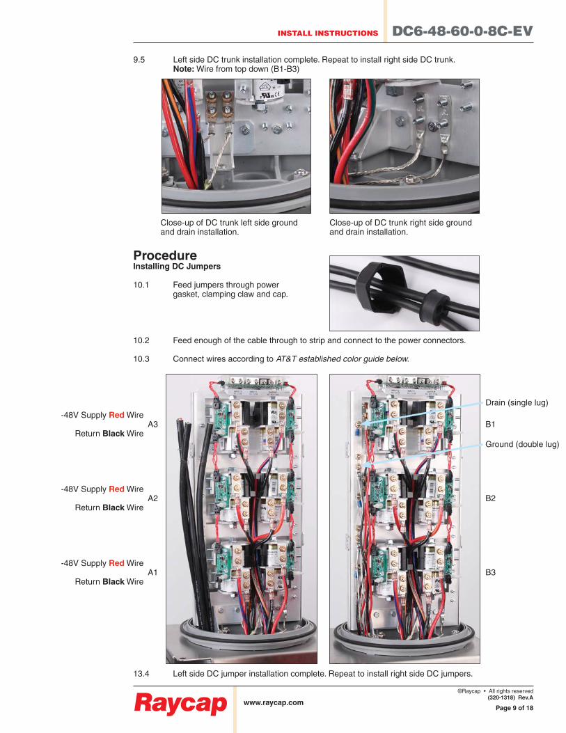
Procedure Installing DC Jumpers
gasket, clamping claw and cap.
10.3 Connect wires according to AT&T established color guide below.
13.4 Left side DC jumper installation complete. Repeat to install right side DC jumpers.
9.5 Left side DC trunk installation complete. Repeat to install right side DC trunk. Note: Wire from top down (B1-B3)
Close-up of DC trunk left side ground and drain installation.
Close-up of DC trunk right side ground and drain installation.
B1
B2
B3
-48V Supply Red WireA3
Return Black Wire
-48V Supply Red WireA2
Return Black Wire
-48V Supply Red WireA1
Return Black Wire
Drain (single lug)
Ground (double lug)
DC6-48-60-0-8C-EV INSTALL INSTRUCTIONS
www.raycap.com
©Raycap • All rights reserved
(320-1318) Rev.A
Page 10 of 18
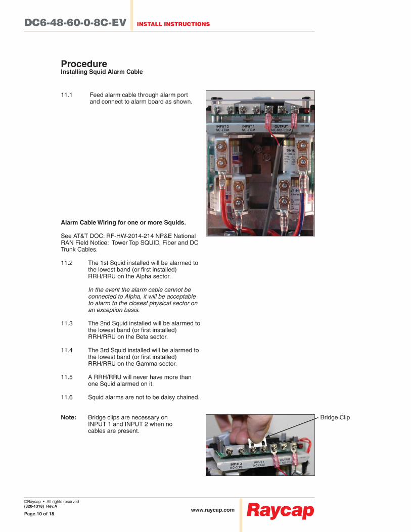
Bridge Clip
Procedure Installing Squid Alarm Cable
and connect to alarm board as shown.
Alarm Cable Wiring for one or more Squids.
Trunk Cables.
11.2 The 1st Squid installed will be alarmed to
RRH/RRU on the Alpha sector.
In the event the alarm cable cannot be connected to Alpha, it will be acceptable to alarm to the closest physical sector on an exception basis.
11.3 The 2nd Squid installed will be alarmed to
RRH/RRU on the Beta sector.
11.4 The 3rd Squid installed will be alarmed to
RRH/RRU on the Gamma sector.
11.5 A RRH/RRU will never have more than one Squid alarmed on it.
11.6 Squid alarms are not to be daisy chained.
Note: Bridge clips are necessary on INPUT 1 and INPUT 2 when no cables are present.
INSTALL INSTRUCTIONS DC6-48-60-0-8C-EV
www.raycap.com
©Raycap • All rights reserved
(320-1318) Rev.A
Page 11 of 18
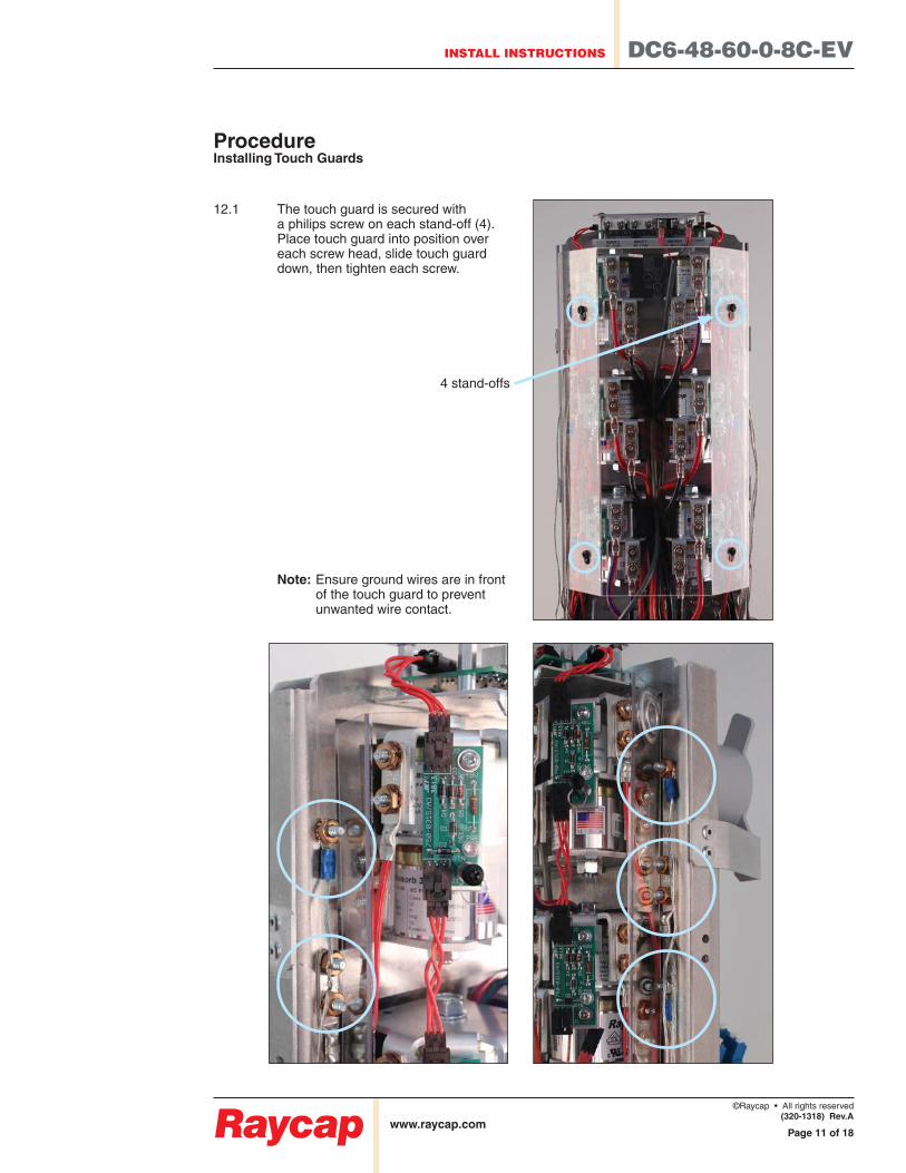
Procedure Installing Touch Guards
12.1 The touch guard is secured with a philips screw on each stand-off (4). Place touch guard into position over each screw head, slide touch guard down, then tighten each screw.
Note: Ensure ground wires are in front of the touch guard to prevent unwanted wire contact.
4 stand-offs

DC6-48-60-0-8C-EV INSTALL INSTRUCTIONS
www.raycap.com
©Raycap • All rights reserved
(320-1318) Rev.A
Page 12 of 18
Procedure Securing Fiber and DC Cables to Mounting Base
13.1 The strain relief bar is designed to accept common cable snap in hangers.
13.2
INSTALL INSTRUCTIONS DC6-48-60-0-8C-EV
www.raycap.com
©Raycap • All rights reserved
(320-1318) Rev.A
Page 13 of 18
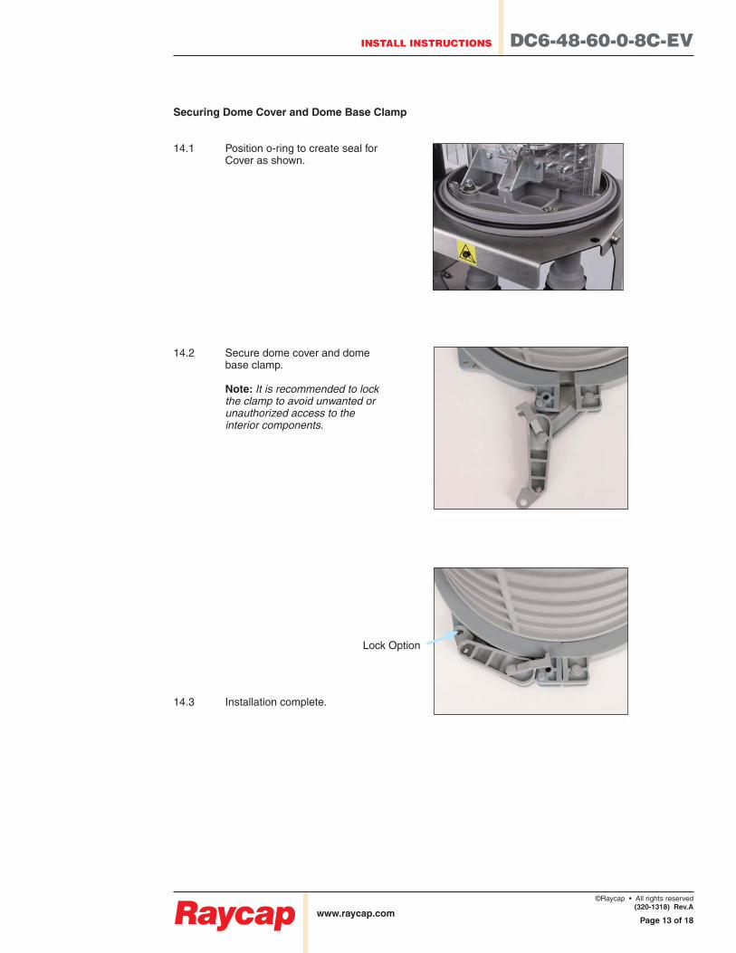
Securing Dome Cover and Dome Base Clamp
14.1 Position o-ring to create seal for Cover as shown.
14.2 Secure dome cover and dome base clamp.
Note: It is recommended to lock the clamp to avoid unwanted or unauthorized access to the interior components.
14.3 Installation complete.
Lock Option
DC6-48-60-0-8C-EV INSTALL INSTRUCTIONS
www.raycap.com
©Raycap • All rights reserved
(320-1318) Rev.A
Page 14 of 18
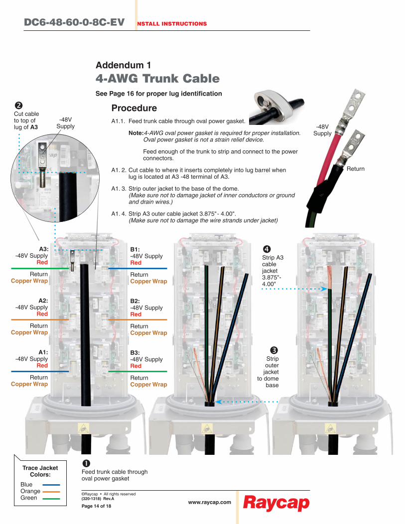
Addendum 1
4-AWG Trunk Cable
Procedure
Note:4-AWG oval power gasket is required for proper installation. Oval power gasket is not a strain relief device.
connectors.
A1. 2. Cut cable to where it inserts completely into lug barrel when lug is located at A3 -48 terminal of A3.
A1. 3. Strip outer jacket to the base of the dome. (Make sure not to damage jacket of inner conductors or ground and drain wires.)
A1. 4. Strip A3 outer cable jacket 3.875" - 4.00". (Make sure not to damage the wire strands under jacket)
Cut cable to top of lug of A3
oval power gasket
-48V Supply
Return
-48V Supply
Trace Jacket Colors:
BlueOrangeGreen
Strip outer
jacket to dome
base
Strip A3 cable jacket 3.875"- 4.00"
A3: -48V Supply
Red
ReturnCopper Wrap
A2:-48V Supply
Red
ReturnCopper Wrap
A1: -48V Supply
Red
ReturnCopper Wrap
B1: -48V SupplyRed
ReturnCopper Wrap
B2:-48V SupplyRed
ReturnCopper Wrap
B3:-48V SupplyRed
ReturnCopper Wrap
©Raycap • All rights reserved
(320-1318) Rev.A
Page 15 of 18
INSTALL INSTRUCTIONS DC6-48-60-0-8C-EV
www.raycap.com
Strip 0.75" of insulation from the red -48V wire and trim the exposed Return wire to a length of 2.25"
Slide boot over cable
Attach cable lugs
to unit
-48V Supply
Return
3.8
75
" -
4.0
0"
2.25"
.75"
A3
A2
A1
B1
B2
B3
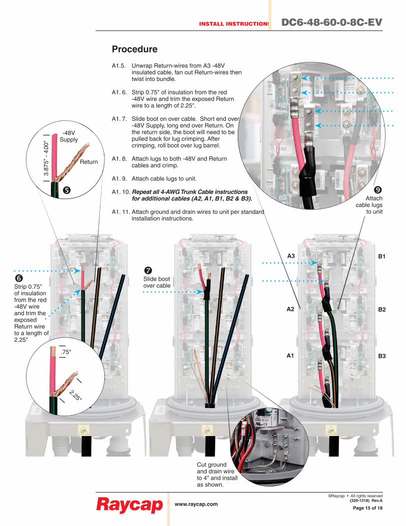
Cut ground and drain wire to 4" and install as shown.
Procedure
A1.5. Unwrap Return-wires from A3 -48V insulated cable, fan out Return-wires then twist into bundle.
A1. 6. Strip 0.75" of insulation from the red -48V wire and trim the exposed Return wire to a length of 2.25".
A1. 7. Slide boot on over cable. Short end over -48V Supply, long end over Return. On the return side, the boot will need to be pulled back for lug crimping. After crimping, roll boot over lug barrel.
A1. 8. Attach lugs to both -48V and Return cables and crimp.
A1. 9. Attach cable lugs to unit.
A1. 10.
A1. 11. Attach ground and drain wires to unit per standard installation instructions.

DC6-48-60-0-8C-EV INSTALL INSTRUCTIONS
www.raycap.com
©Raycap • All rights reserved
(320-1318) Rev.A
Page 16 of 18
Notes


DC6-48-60-0-8C-EV INSTALL INSTRUCTIONS
www.raycap.com
©Raycap • All rights reserved
(320-1318) Rev.A
Page 18 of 18

![What's your `eX5 - ARTHURarthur.hpt.at/php/online_links/links/LP_21456.pdf · 71 unit ( 8]z[ dg xdd`4 4gcf vjg rctcitcrj qp vjg tkijv cpf eqpegpvtcvg qp vjg igpgtcn kfgc 6jgp eqppgev](https://img.pdfslide.net/doc/110x75/5e0ae2d2a4f7bb729e6b3f48/whats-your-ex5-71-unit-8z-dg-xdd4-4gcf-vjg-rctcitcrj-qp-vjg-tkijv-cpf-eqpegpvtcvg.jpg)