Embed Size (px)
Citation preview
DCB/ASM Scenario Step1 System Definition Final
Document information
Project title Network Operations & Monitoring sub-system definition
Project N° 13.02.03
Project Manager ECTRL
Deliverable Name DCB/ASM Scenario Step1 System Definition Final
Deliverable ID D02
Edition 00.01.00
Template Version 02.00.00
Task contributors
AENA, ENAV, EUROCONTROL, INDRA, NATS
Please complete the advanced properties of the document
Abstract
This document is the Technical Specification for the “Cooperative Scenario Planning” Functional Block. It addresses the system required to ensure the support at local/sub-
regional level of the collaborative processes with the local and sub-regional actors,
Airports and all Airspace Users (including the military). It is based upon operational
requirements, and contains technical requirements specifying this system. The
requirements are derived from the P04.07.07 [1] Preliminary Operational Service and Environment Definition (OSED), deliverable 04.07.07.D25. The system specified in this
document is intended to cover the PERSEO module and the PIVL module enhancement
operational requirements stated in P04.07.07.D25 Final OSED [1], so there is no
traceability in this document for OCOT or HLDR requirements, as they are do not need a
v3 prototype to be delivered by P13.02.03 for validation.

Project ID 13.02.276 D02 – DCB/ASM Scenario Step1 System Definition Final Edition: 00.01.00
1 of 45
Authoring & Approval
Prepared By
Name & company Position / Title Date
Rafael Pereira / INDRA Task Contributor 21/03/2013
José Manuel Cordero /AENA Task Leader 22/03/2013
Reviewed By
Name & company Position / Title Date
Javier Poveda /AENA Contributor 15/03/2013
Steve Williams / NATS Reviewer 15/03/2013
Debora Palombi / ENAV Reviewer 15/03/2013
Bob Lewis /SELEX Project Member 15/03/2013
Alexander Dorta / AENA P04.07.07 PM 15/03/2013
Hughes Robin / EUROCONTROL P13.01.01 PM 15/03/2013
Andrew Hately / EUROCONTROL P13.02.03 PM 15/03/2013
Dominique Latge / THALES Project Member 15/03/2013
Approved By
Name & company Position / Title Date
Jose Manuel Cordero /AENA Contributor 15/03/2013
Steve Williams / NATS Reviewer 20/03/2013
Debora Palombi / ENAV Reviewer 20/03/2013
Bob Lewis /SELEX Project Member 21/03/2013
Alexander Dorta / AENA P04.07.07 PM 15/03/2013
Hughes Robin / EUROCONTROL P13.01.01 PM 21/03/2013
Andrew Hately / EUROCONTROL P13.02.03 PM 18/03/2013
Dominique Latge / THALES Project Member 21/03/2013
Document History
Edition Date Status Author Justification
00.00.01 10/01/2013 Draft Jose Manuel Cordero
Draft
00.00.02 17/01/2013 Draft Jose Manuel Cordero
Draft
00.00.02 24/01/2013 Draft Rafael Pereira Internal Draft Review
00.00.03 14/02/2013 Final Jose Manuel Cordero, Rafael Pereira
Final Version to formal review
00.01.00 06/03/2013 Final Jose Manuel Cordero
Approved version
Intellectual Property Rights (foreground) This deliverable consists of foreground owned by one or several Members or their Affiliates. Specifically, part of this foreground is owned by AENA and the remaining part is owned by INDRA.

Project ID 13.02.276 D02 – DCB/ASM Scenario Step1 System Definition Final Edition: 00.01.00
2 of 45
Table of Contents 1. EXECUTIVE SUMMARY ............................................................................................................................ 4
2. INTRODUCTION ......................................................................................................................................... 5
2.1 PURPOSE OF THE DOCUMENT ................................................................................................................ 5 2.2 INTENDED READERSHIP .......................................................................................................................... 6 2.3 INPUTS FROM OTHER PROJECTS ............................................................................................................ 6 2.4 REQUIREMENTS DEFINITIONS – GENERAL GUIDANCE .......................................................................... 6 2.5 FUNCTIONAL BLOCK PURPOSE............................................................................................................... 7 2.6 FUNCTIONAL BLOCK OVERVIEW ............................................................................................................. 7 2.7 ACRONYMS AND TERMINOLOGY ............................................................................................................. 8
3 GENERAL FUNCTIONAL BLOCK DESCRIPTION ............................................................................ 11
3.1 CONTEXT .............................................................................................................................................. 11 3.2 FUNCTIONAL BLOCK MODES AND STATES ........................................................................................... 11
3.2.1 Functional Block States ............................................................................................................ 11 3.2.2 Functional Block Modes ............................................................................................................ 11 3.2.2.1 Historical Mode ........................................................................................................................... 11 3.2.2.2 Real Mode ................................................................................................................................... 11 3.2.2.3 Mixed Mode ................................................................................................................................ 11
3.3 MAJOR FUNCTIONAL BLOCK CAPABILITIES .......................................................................................... 11 3.3.1 Data Acquisition ......................................................................................................................... 11 3.3.2 Optimization Analysis ................................................................................................................ 12 3.3.3 Display ......................................................................................................................................... 13
3.4 USER CHARACTERISTICS ..................................................................................................................... 13 3.5 OPERATIONAL SCENARIOS................................................................................................................... 13 3.6 FUNCTIONAL ......................................................................................................................................... 13
3.6.1 Functional decomposition ......................................................................................................... 13 3.6.2 Functional analysis .................................................................................................................... 14
3.7 SERVICE VIEW ...................................................................................................................................... 15
4 FUNCTIONAL BLOCK FUNCTIONAL AND NON-FUNCTIONAL REQUIREMENTS .................. 16
4.1 CAPABILITIES ........................................................................................................................................ 16 4.1.1 Functional Requirements .......................................................................................................... 16 4.1.2 HMI Requirements ..................................................................................................................... 29 4.1.3 Configuration Requirements .......................................................................................................... 32
4.2 ADAPTABILITY ....................................................................................................................................... 34 4.3 PERFORMANCE CHARACTERISTICS ..................................................................................................... 34
4.3.1Performances Requirements .......................................................................................................... 34 4.4 SAFETY & SECURITY ............................................................................................................................ 35 4.5 MAINTAINABILITY .................................................................................................................................. 35 4.6 RELIABILITY .......................................................................................................................................... 35
4.6.1 Reliability Requirements ........................................................................................................... 35 4.7 FUNCTIONAL BLOCK INTERNAL DATA REQUIREMENTS ........................................................................ 38 4.8 DESIGN AND CONSTRUCTION CONSTRAINTS ...................................................................................... 38 4.9 FUNCTIONAL BLOCK INTERFACE REQUIREMENTS ............................................................................... 38
4.9.1 Interface Configuration Requirements .................................................................................... 38 4.10 COMPLIANCE MATRIX ........................................................................................................................... 41
5 REFERENCES ........................................................................................................................................... 43
APPENDIX A TRACEABILITY ................................................................................................................. 44
Project ID 13.02.276 D02 – DCB/ASM Scenario Step1 System Definition Final Edition: 00.01.00
3 of 45
List of figures Figure 1: Flow of documentation overview [PMP] ................................................................................... 6 Figure 2: FB Cooperative Scenario Planning .......................................................................................... 8 Figure 3: “DCB/ASM Scenario Management” system functional decomposition .................................. 14 Figure 4: DCB/ASM Scenario Management system Data Flow Diagram ............................................. 15
Project ID 13.02.276 D02 – DCB/ASM Scenario Step1 System Definition Final Edition: 00.01.00
4 of 45
1.Executive summary
This document sets out the Technical Specification (TS) and System Definition, describing the requirements pertinent to the implementation of “DCB/ASM Scenario management” system in step1 associated to “Cooperative Scenario Planning” Functional Block. It is defined in the context of Step 1 of the SESAR Validation and Verification (V&V) Storyboard.
The main function provided by DCB/ASM Scenario management system in Step 1 is to support decision making about operational sectorization in a local/sub-regional scope, taking into account network effects at a local/sub-regional level. This decision-making support is provided by sectorization analysis and optimal solution suggestion for each Area Control Center, realized by this sub-system as an element of the whole functional block.
DCB/ASM Scenario management system supports elaboration of pre-defined scenarios in a collaborative way with local/sub-regional actors and AAMS/ Cooperative Scenario planning.
The requirements have been worked out in such a way that they actually describe the services provided by the sub-system and that they are as much as possible independent from the internal design.
Two local modules of this system, called PERSEO and PIVL, will be enhanced according to P04.07.07 operational requirements and will be used to support Step 1 P04.07.07 validation activities. According to P04.07.07, the system specified in this document is intended to cover only the PERSEO and PIVL operational requirements, as expressed in the Final OSED [1]. Only PERSEO and PIVL enhanced modules and its relationship with ATC System is intended to be validated through a v3 prototype; thereby, and in terms of P04.07.07 Initial OSED, there is no traceability in this document for OCOT or HLDR requirements.
Project ID 13.02.276 D02 – DCB/ASM Scenario Step1 System Definition Final Edition: 00.01.00
5 of 45
2.Introduction Controller workload (traffic complexity) in situations of high demand, and/or very busy airspace can be
so high that it will becomes impossible to manage it with conventional ATC means; managing
controllers' workload by balancing capacity with demand becomes crucial.
Dynamic resizing and change of sector's shape and volume contributes to distribute the workload with
respect to the capacity of sectors in one centre/FAB and it could be done only through automated
systems which continuously evaluate traffic complexity and propose optimum sectorization solutions.
This will provide possibilities for the users to fly as close as possible to their "business trajectories",
doing an optimum use of human and airspace capacity.
2.1 Purpose of the document This document describes the technical requirements for the DCB/ASM Scenario management system
to be developed. This information will serve as a starting point for further design and development of a
prototype to be verified and validated (by P04.07.07) in the context of Step 1 SESAR V&V Roadmap.
These requirements describe functional and capabilities specifications, covering performance,
physical characteristics and environmental and facility conditions under which the functional block has
to perform.
This document covers functional, non-functional and interface requirements for the PERSEO and
PIVL tools, as specified in the P04.07.07 Final OSED [1]. Only the PERSEO and PIVL prototypes as
specified in P04.07.07 are intended to be validated through a v3 prototype to be delivered by
P13.02.03; thereby, there is no traceability in this document for OCOT or HLDR requirements, as
stated in the P04.07.07 Final OSED [1].
The relations between this technical specification and the other SESAR deliverables are illustrated in
Figure 1.

Project ID 13.02.276 D02 – DCB/ASM Scenario Step1 System Definition Final Edition: 00.01.00
6 of 45
Figure 1: Flow of documentation overview [PMP]
2.2 Intended readership
This document is intended for the following audience:
•Operational projects: P04.07.07 (Implementation of the Dynamic Capacity Management in a high density area) as the sources of the operational requirements
•WPB4.3 as the SESAR Technical Architect
•P13.01.01 (Network Sub-System Definition & Verification) is interested in the document to identify and maintain the functional block list and to contribute to the definition of the architecture.
2.3 Inputs from other projects
Project 04.07.07 is identified as the source of a first set of inputs requirements impacting the DCB/ASM Cooperative Scenario planning FB.
2.4 Requirements Definitions – General Guidance Requirements have been developed according to the SESAR Requirements and V&V Guidelines[3].
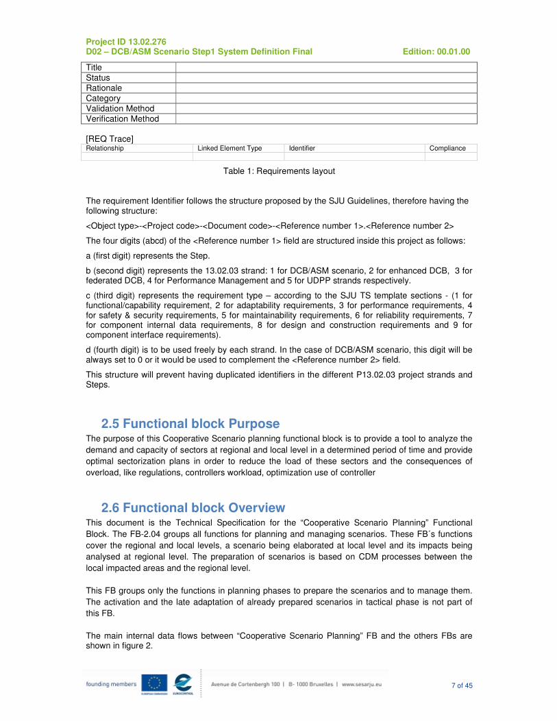
In order to facilitate importing of the requirements in a DOORS data base it has been used the toolbox delivered by the IS that provides the following layout described in [2].
The layout is illustrated below:
[REQ]
Identifier
Requirement
Project ID 13.02.276 D02 – DCB/ASM Scenario Step1 System Definition Final Edition: 00.01.00
7 of 45
Title
Status
Rationale
Category
Validation Method
Verification Method
[REQ Trace] Relationship Linked Element Type Identifier Compliance
Table 1: Requirements layout
The requirement Identifier follows the structure proposed by the SJU Guidelines, therefore having the following structure:
<Object type>-<Project code>-<Document code>-<Reference number 1>.<Reference number 2>
The four digits (abcd) of the <Reference number 1> field are structured inside this project as follows:
a (first digit) represents the Step.
b (second digit) represents the 13.02.03 strand: 1 for DCB/ASM scenario, 2 for enhanced DCB, 3 for federated DCB, 4 for Performance Management and 5 for UDPP strands respectively.
c (third digit) represents the requirement type – according to the SJU TS template sections - (1 for functional/capability requirement, 2 for adaptability requirements, 3 for performance requirements, 4 for safety & security requirements, 5 for maintainability requirements, 6 for reliability requirements, 7 for component internal data requirements, 8 for design and construction requirements and 9 for component interface requirements).
d (fourth digit) is to be used freely by each strand. In the case of DCB/ASM scenario, this digit will be always set to 0 or it would be used to complement the <Reference number 2> field.
This structure will prevent having duplicated identifiers in the different P13.02.03 project strands and Steps.
2.5 Functional block Purpose The purpose of this Cooperative Scenario planning functional block is to provide a tool to analyze the
demand and capacity of sectors at regional and local level in a determined period of time and provide
optimal sectorization plans in order to reduce the load of these sectors and the consequences of
overload, like regulations, controllers workload, optimization use of controller
2.6 Functional block Overview This document is the Technical Specification for the “Cooperative Scenario Planning” Functional
Block. The FB-2.04 groups all functions for planning and managing scenarios. These FB´s functions
cover the regional and local levels, a scenario being elaborated at local level and its impacts being
analysed at regional level. The preparation of scenarios is based on CDM processes between the
local impacted areas and the regional level.
This FB groups only the functions in planning phases to prepare the scenarios and to manage them.
The activation and the late adaptation of already prepared scenarios in tactical phase is not part of
this FB.
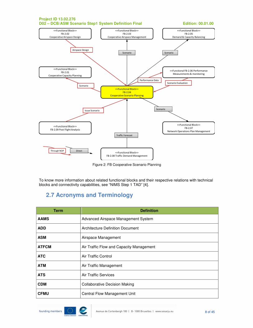
The main internal data flows between “Cooperative Scenario Planning” FB and the others FBs are shown in figure 2.
Project ID 13.02.276 D02 – DCB/ASM Scenario Step1 System Definition Final Edition: 00.01.00
8 of 45
<<Functional Block>>
FB-2.01
Cooperative Capacity Planning
<<Functional Block>>
FB-2.02
Cooperative Airspace Design
<<Functional Block>>
FB-2.03
Cooperative Airspace Management
<<Functional Block>>
FB-2.04
Cooperative Scenario Planning
<<Functional Block>>
FB-2.05
Demand & Capacity Balancing
<<Functional FB-2.06 Performance
Measurements & monitoring
<<Functional Block>>
FB-2.07
Network Operations Plan Management
<<Functional Block>>
FB-2.08 Traffic Demand Management
Scenario
Airspace Design
Performance Data
Scenario
Traffic Forecast
Scenario
Scenario Evaluation
Through NOP Direct
Scenario
<<Functional Block>>
FB-2.09 Post Flight Analysis
Issue Scenario
Figure 2: FB Cooperative Scenario Planning
To know more information about related functional blocks and their respective relations with technical blocks and connectivity capabilities, see “NIMS Step 1 TAD” [4].
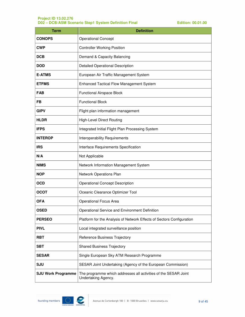
2.7 Acronyms and Terminology
Term Definition
AAMS Advanced Airspace Management System
ADD Architecture Definition Document
ASM Airspace Management
ATFCM Air Traffic Flow and Capacity Management
ATC Air Traffic Control
ATM Air Traffic Management
ATS Air Traffic Services
CDM Collaborative Decision Making
CFMU Central Flow Management Unit
Project ID 13.02.276 D02 – DCB/ASM Scenario Step1 System Definition Final Edition: 00.01.00
9 of 45
Term Definition
CONOPS Operational Concept
CWP Controller Working Position
DCB Demand & Capacity Balancing
DOD Detailed Operational Description
E-ATMS European Air Traffic Management System
ETFMS Enhanced Tactical Flow Management System
FAB Functional Airspace Block
FB Functional Block
GIPV Flight plan information management
HLDR High-Level Direct Routing
IFPS Integrated Initial Flight Plan Processing System
INTEROP Interoperability Requirements
IRS Interface Requirements Specification
N/A Not Applicable
NIMS Network Information Management System
NOP Network Operations Plan
OCD Operational Concept Description
OCOT Oceanic Clearance Optimizer Tool
OFA Operational Focus Area
OSED Operational Service and Environment Definition
PERSEO Platform for the Analysis of Network Effects of Sectors Configuration
PIVL Local integrated surveillance position
RBT Reference Business Trajectory
SBT Shared Business Trajectory
SESAR Single European Sky ATM Research Programme
SJU SESAR Joint Undertaking (Agency of the European Commission)
SJU Work Programme The programme which addresses all activities of the SESAR Joint Undertaking Agency.
Project ID 13.02.276 D02 – DCB/ASM Scenario Step1 System Definition Final Edition: 00.01.00
10 of 45
Term Definition
SESAR Programme The programme which defines the Research and Development activities and Projects for the SJU.
SPR Safety and Performance Requirements
SWIM System-Wide Information Management
TAD Technical Architecture Description
TB Technical Block
TS Technical Specification
Shift One of three time periods in which divides the day of operation
Project ID 13.02.276 D02 – DCB/ASM Scenario Step1 System Definition Final Edition: 00.01.00
11 of 45
3 General Functional block Description
3.1 Context This “Cooperative Scenario planning” Functional Block is enclosed in a local context of ATM, so that, using ATCs predefined sectorizations, declared capacity, and the demand over the operation day (in each sector of every pre-defined sectorization), it can propose an optimal sectorization plan along a time, in order to cover the needs for making decisions in each ATC airspace.
3.2 Functional block Modes and States
3.2.1 Functional Block States
Not Applicable
3.2.2 Functional Block Modes
This FB can work in three modes that have to be selected by the user to simulate and analyze sectorizations to be set in each ATC, over the operation day.
3.2.2.1 Historical Mode
This FB in Historical mode will perform an analysis with historical data stored in a database.
This mode can also be used to simulate sectorizations in order to improve the process in a day with a similar type of traffic. Additionally, the mining of historical data is used for reliable prediction of demand in a long-term horizon.
3.2.2.2 Real Mode
This FB in Real mode will perform an analysis with the latest available data provided by IFPS. The IFPS has to be configured to provide the data as a sequence of TCP/IP messages associated with events that occur in the IFPS, in a format known by the system.
This information provided by IFPS allows the user to view the evolution of flights and thus the system calculate the metrics associated demand by sectors that evolve these flights and to determine the optimal configuration plan.
3.2.2.3Mixed Mode
Real data may be combined with historical data to simulate traffic conditions and to determine the best optimal configuration plan using more information than the Real Mode.
3.3 Major Functional block Capabilities
This section gives an overview of the system associated to this functional block main requirements and the grouping of functionalities regarding these requirements.
This system is named “DCB/ASM Scenario Management System” but it will be named as “the system” in the next sections.
3.3.1Data Acquisition
§The system shall be connected to the online ATC system to receive configuration settings for the analysis that will be performed.
§The system shall compute the demand indicators from data received from the online ATC system for real or mixed traffic data type analysis.
Project ID 13.02.276 D02 – DCB/ASM Scenario Step1 System Definition Final Edition: 00.01.00
12 of 45
§The system shall compute the demand indicators from historical data received from a database for historical or mixed traffic data type analysis.
§The system shall use the following metrics to compute the demand indicators, metrics that allow the system to determine the demand in a sector:
o The number of aircraft within the sector in each time interval during the period of the analysis.
o The capacity of each sector per each time interval during the period of the analysis.
o The Occupancy Factor, relation between demand and capacity within the sector in each time interval during the period of the analysis.
o Number of Saturation flights, difference between demand and capacity within the sector in each time interval during the period of the analysis.
§The system should be connected to a database to retrieve historical information that allows demand indicator calculation as well as storage of the calculated demand indicators for later analysis or re-use.
§ The system should validate the data received or loaded in order to check that is formatted properly and consistent with the parameters an mode which determine the analysis to be performed. If this checking is not done the calculation may be done with the wrong information and thereby the reliability of the output would decrease.
3.3.2Optimization Analysis
§ The goal of this optimization/analysis is to determine the optimal sequence of predefined airspace sectorizations in a determined work shift, called "sectorization plan”, by trying to achieve even distribution of workload. To achieve this goal, the system, based on the ATC predefined airspace sectorizations for the analysis is performed, selects the optimal sequence by visiting the choices and constrains for each moment.
§The system should provide a default setup for optimal sectorization plan calculation constraints and a way to select it by the user.
§The optimal sectorization in a period of time shall be calculated taking into account the following parameters: Number of Controller Working Positions (CWP), mean value of load/capacity of each CWP, number of overloaded CWP, number of overloaded periods
§The optimal sectorizations calculated shall be one of the predefined and standardized sectorizations for the control area
§The system shall calculate optimal sectorization plan for the ATC Unit, predefined sectorizations, data source and constraints determined by the user or configured by default. For historical traffic data analysis, calculation will be performed for the time period date determined by the user. In a real, or mixed traffic data type analysis, calculation will be performed for the time period related to the system date.
§The system should compute a list of optimal sectorization plan, by finding time intervals for sectors to reduce the number of flights on saturation that cause the sectors traversed by them are overloaded, called saturation flights.
§The system should calculate a metric for each optimal sectorization plan by finding the minimum dispersion of the occupancy factor between sectors that belongs to a predefined sectorization of every plan in a time interval.
§The system should determine the best optimal sectorization plan and the other sectorization plans order by its metrics
§The system should provide a comparison between the best optimal sectorization and the operational sectorization for an interval of time determined for the current sectorization.
§The system should store the best optimal sectorization plan for historical purposes.
Project ID 13.02.276 D02 – DCB/ASM Scenario Step1 System Definition Final Edition: 00.01.00
13 of 45
3.3.3Display
§The system should display charts showing computed demand indicator for each sector of each predefined sectorization in every time interval of the time period for which analysis will be performed.
§The system should display tables showing computed demand indicator for each sector of each predefined sectorization in every time interval of the time period for which analysis will be performed.
§The system should inform the user about errors detected.
§The system should display the optimal sectorization plan and the metrics used for optimization per interval and sectors that are part of some of the sectorizations proposed.
§The system should display the optimal sectorization plan list as a result of the optimization analysis.
§The system should provide the user a way to display any stored optimal sectorization plan determined by the system in previous analysis.
3.4User Characteristics
Intended users:
• Flow Manager Position (FMP): Flow manager position uses the local tool to analyze sectorizations to be set, in each ATC, over the operation day.
• ACC Supervisor: ACC supervisor will use the ATC system to analyze and decide sectorizations to be set, in each ATC, over the operation day or the operation day.
3.5Operational Scenarios
The operational scenario for this FB, according to a local/subregional scope, will be an ATC control area in order to simulate and analyze sectorizations to be set in this ATC center, over the operation day. Pre-defined sectorizations for the selected ACC will be previously loaded on the tool.
3.6Functional
3.6.1Functional decomposition
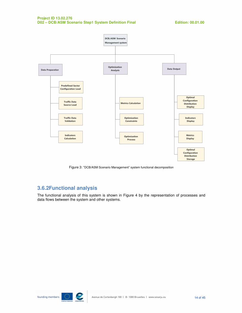
The functional decomposition of the “DCB/ASM Scenario Management” system is illustrated in figure 3.
Project ID 13.02.276 D02 – DCB/ASM Scenario Step1 System Definition Final Edition: 00.01.00
14 of 45
Figure 3: “DCB/ASM Scenario Management” system functional decomposition
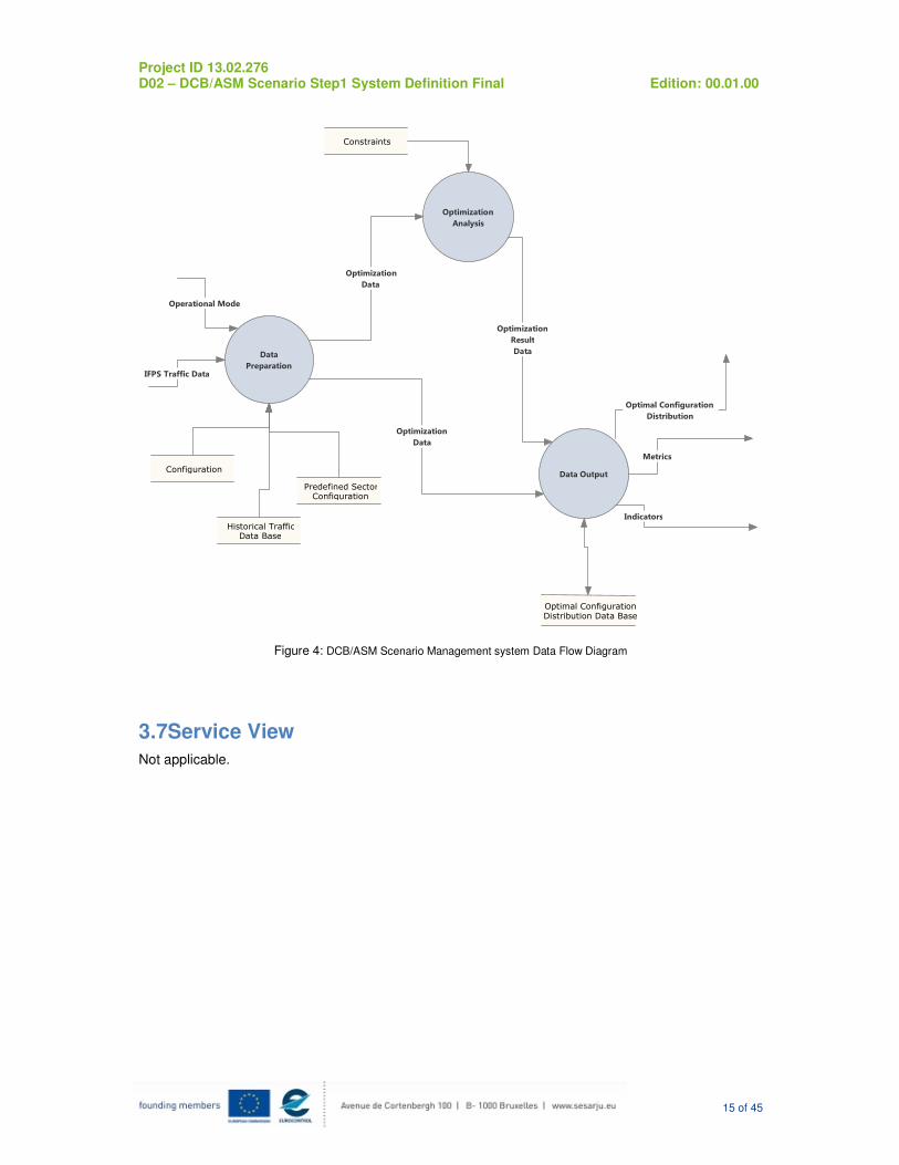
3.6.2Functional analysis
The functional analysis of this system is shown in Figure 4 by the representation of processes and data flows between the system and other systems.
Traffic Data
Source Load
DCB/ASM Scenario
Management system
Data Preparation
Traffic Data
Validation
Indicators
Calculation
Optimization
Analysis
Metrics Calculation
Optimization
Process
Optimization
Constraints
Data Output
Optimal
Configuration
Distribution Display
Indicators
Display
Metrics Display
Optimal
Configuration
Distribution
Storage
Predefined Sector Configuration Load
Project ID 13.02.276 D02 – DCB/ASM Scenario Step1 System Definition Final Edition: 00.01.00
15 of 45
Figure 4: DCB/ASM Scenario Management system Data Flow Diagram
3.7Service View
Not applicable.
Data
Preparation
Operational Mode
Configuration
Historical TrafficData Base
IFPS Traffic Data
Predefined SectorConfiguration
Optimization Analysis
Constraints
Optimization
Data
Data Output
Optimization
Result
Data
Optimal Configuration
Distribution
Metrics
Indicators
Optimal ConfigurationDistribution Data Base
Optimization
Data
Project ID 13.02.276 D02 – DCB/ASM Scenario Step1 System Definition Final Edition: 00.01.00
16 of 45
4Functional block Functional and non-Functional Requirements
4.1Capabilities
4.1.1 Functional Requirements
Identifier REQ-13.02.03-TS-1110.0001
Requirement The system shall provide the user a way to select the ATC Unit for which analysis will be performed.
Title ATC Unit selector for Optimization Analysis
Status <In Progress>
Rationale User Input parameter for Data Acquisition and Optimization Analysis. PIVL module does not need to meet this requirement as is a special case of implementation that already knows internal ATC Unit information.
Category <Functional>
Validation Method
Verification Method <Test>
[REQ Trace]
Relationship Linked Element Type Identifier Compliance
<ALLOCATED_TO> <Functional block> FB-2.04 N/A <APPLIES_TO> <Operational Focus Area> OFA05.03.04 N/A
<SATISFIES> <Enabler> Enabler code <Full>
<SATISFIES> <ATMS Requirement> REQ-04.07.07-OSED-DCM1.0001 <Partial>
<SATISFIES> <ATMS Requirement> REQ-04.07.07-OSED-DCM1.0009 <Partial>
[REQ]
Identifier REQ-13.02.03-TS-1110.0002
Requirement The system shall provide the user a way to select the date for which analysis will be performed.
Title Date selector for Optimization Analysis
Status <In Progress>
Rationale User Input parameter for Data Acquisition and Optimization Analysis in Historical Mode. PIVL module does not need to meet this requirement as is a special case of implementation that already knows internal ATC Unit information.
Category <Functional>
Validation Method
Verification Method <Test>
[REQ Trace]
Relationship Linked Element Type Identifier Compliance
<ALLOCATED_TO> <Functional block> FB-2.04 N/A
<APPLIES_TO> <Operational Focus Area> OFA05.03.04 N/A
<SATISFIES> <ATMS Requirement> REQ-04.07.07-OSED-DCM1.0001 <Partial>
<SATISFIES> <ATMS Requirement> REQ-04.07.07-OSED-DCM1.0009 <Partial>
[REQ]
Identifier REQ-13.02.03-TS-1110.0003
Requirement The system shall provide the user a way to select the shift (Morning, Afternoon or Night), for which analysis will be performed.
Title Shift selector for Optimization Analysis
Status <In Progress>
Rationale User Input parameter for Data Acquisition and Optimization Analysis. PIVL module does not need to meet this requirement as is a special case of
Project ID 13.02.276 D02 – DCB/ASM Scenario Step1 System Definition Final Edition: 00.01.00
17 of 45
implementation that already knows internal ATC Unit information
Category <Functional>
Validation Method
Verification Method <Test>
[REQ Trace]
Relationship Linked Element Type Identifier Compliance
<ALLOCATED_TO> <Functional block> FB-2.04 N/A
<APPLIES_TO> <Operational Focus Area> OFA05.03.04 N/A <SATISFIES> <ATMS Requirement> REQ-04.07.07-OSED-DCM1.0001 <Partial>
<SATISFIES> <ATMS Requirement> REQ-04.07.07-OSED-DCM1.0009 <Partial>
[REQ]
Identifier REQ-13.02.03-TS-1110.0008
Requirement The system shall provide the user a way to select the type of traffic data for which analysis will be performed: real, historical or mixed.
Title Type of traffic data selector
Status <In Progress>
Rationale User Input parameter for Data Acquisition, allowing the user to work with both sources or, if desired, with only one of them. PIVL module does not need to meet this requirement as is a special case of implementation that already knows internal ATC Unit information
Category <Functional>
Validation Method
Verification Method <Test>
[REQ Trace]
Relationship Linked Element Type Identifier Compliance
<ALLOCATED_TO> <Functional block> FB-2.04 N/A <APPLIES_TO> <Operational Focus Area> OFA05.03.04 N/A
<SATISFIES> <ATMS Requirement> REQ-04.07.07-OSED-DCM1.0010 <Partial>
[REQ]
Identifier REQ-13.02.03-TS-1110.0012
Requirement The system shall provide the user a way to set up the sectorization currently in operation.
Title Sectorization selector
Status <In Progress>
Rationale User input for Optimization Analysis. PIVL module does not need to meet this requirement as is a special case of implementation that already knows internal ATC Unit information
Category <Functional>
Validation Method
Verification Method <Test>
[REQ Trace]
Relationship Linked Element Type Identifier Compliance
<ALLOCATED_TO> <Functional block> FB-2.04 N/A
<APPLIES_TO> <Operational Focus Area> OFA05.03.04 N/A <SATISFIES> <ATMS Requirement> REQ-04.07.07-OSED-DCM1.0007 <Partial>
<SATISFIES> <ATMS Requirement> REQ-04.07.07-OSED-DCM1.00012 <Partial>
[REQ]
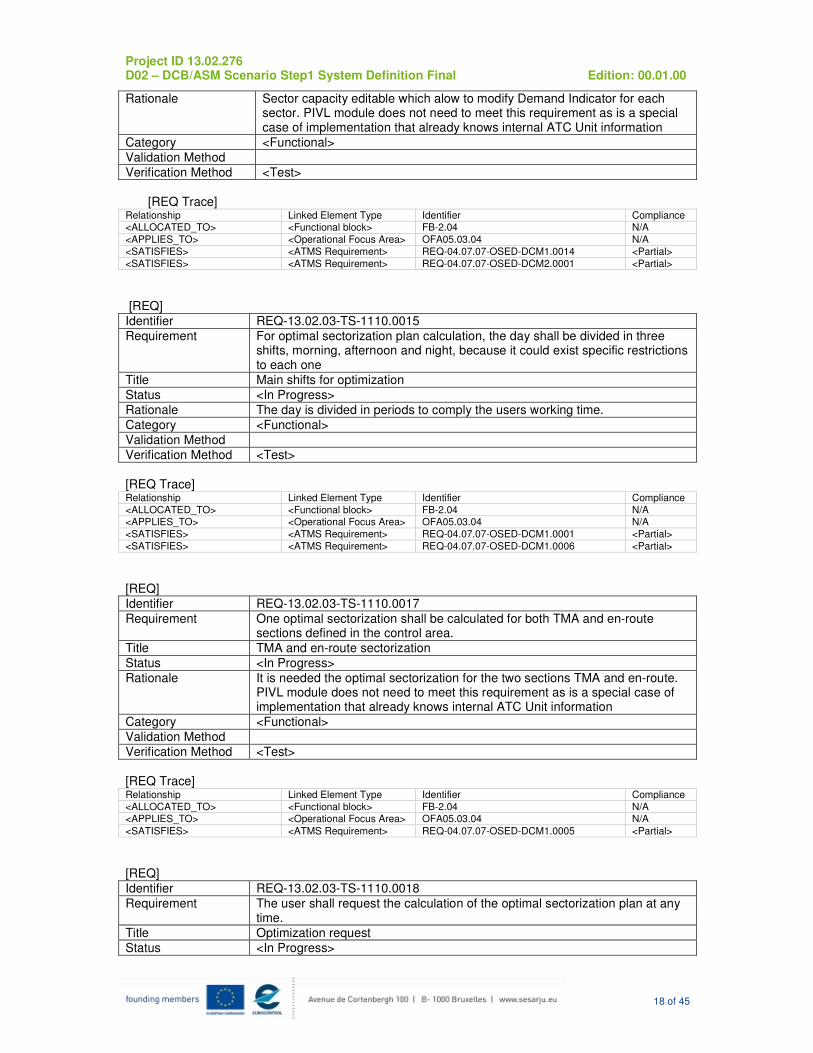
Identifier REQ-13.02.03-TS-1110.0013
Requirement The system shall provide the user a way to know the capacity for each sector for which analysis will be performed.
Title Sector Capacity Edition
Status <In Progress>
Project ID 13.02.276 D02 – DCB/ASM Scenario Step1 System Definition Final Edition: 00.01.00
18 of 45
Rationale Sector capacity editable which alow to modify Demand Indicator for each sector. PIVL module does not need to meet this requirement as is a special case of implementation that already knows internal ATC Unit information
Category <Functional>
Validation Method
Verification Method <Test>
[REQ Trace]
Relationship Linked Element Type Identifier Compliance <ALLOCATED_TO> <Functional block> FB-2.04 N/A
<APPLIES_TO> <Operational Focus Area> OFA05.03.04 N/A
<SATISFIES> <ATMS Requirement> REQ-04.07.07-OSED-DCM1.0014 <Partial>
<SATISFIES> <ATMS Requirement> REQ-04.07.07-OSED-DCM2.0001 <Partial>
[REQ]
Identifier REQ-13.02.03-TS-1110.0015
Requirement For optimal sectorization plan calculation, the day shall be divided in three shifts, morning, afternoon and night, because it could exist specific restrictions to each one
Title Main shifts for optimization
Status <In Progress>
Rationale The day is divided in periods to comply the users working time.
Category <Functional>
Validation Method
Verification Method <Test>
[REQ Trace] Relationship Linked Element Type Identifier Compliance
<ALLOCATED_TO> <Functional block> FB-2.04 N/A <APPLIES_TO> <Operational Focus Area> OFA05.03.04 N/A
<SATISFIES> <ATMS Requirement> REQ-04.07.07-OSED-DCM1.0001 <Partial>
<SATISFIES> <ATMS Requirement> REQ-04.07.07-OSED-DCM1.0006 <Partial>
[REQ]
Identifier REQ-13.02.03-TS-1110.0017
Requirement One optimal sectorization shall be calculated for both TMA and en-route sections defined in the control area.
Title TMA and en-route sectorization
Status <In Progress>
Rationale It is needed the optimal sectorization for the two sections TMA and en-route. PIVL module does not need to meet this requirement as is a special case of implementation that already knows internal ATC Unit information
Category <Functional>
Validation Method
Verification Method <Test>
[REQ Trace] Relationship Linked Element Type Identifier Compliance
<ALLOCATED_TO> <Functional block> FB-2.04 N/A <APPLIES_TO> <Operational Focus Area> OFA05.03.04 N/A
<SATISFIES> <ATMS Requirement> REQ-04.07.07-OSED-DCM1.0005 <Partial>
[REQ]
Identifier REQ-13.02.03-TS-1110.0018
Requirement The user shall request the calculation of the optimal sectorization plan at any time.
Title Optimization request
Status <In Progress>
Project ID 13.02.276 D02 – DCB/ASM Scenario Step1 System Definition Final Edition: 00.01.00
19 of 45
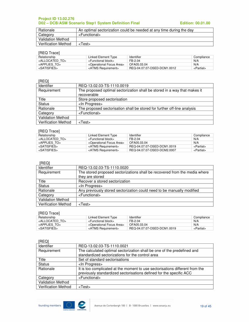
Rationale An optimal sectorization could be needed at any time during the day
Category <Functional>
Validation Method
Verification Method <Test>
[REQ Trace] Relationship Linked Element Type Identifier Compliance
<ALLOCATED_TO> <Functional block> FB-2.04 N/A
<APPLIES_TO> <Operational Focus Area> OFA05.03.04 N/A <SATISFIES> <ATMS Requirement> REQ-04.07.07-OSED-DCM1.0012 <Partial>
[REQ]
Identifier REQ-13.02.03-TS-1110.0019
Requirement The proposed optimal sectorization shall be stored in a way that makes it recoverable
Title Store proposed sectorisation
Status <In Progress>
Rationale The proposed sectorisation shall be stored for further off-line analysis
Category <Functional>
Validation Method
Verification Method <Test>
[REQ Trace] Relationship Linked Element Type Identifier Compliance
<ALLOCATED_TO> <Functional block> FB-2.04 N/A
<APPLIES_TO> <Operational Focus Area> OFA05.03.04 N/A
<SATISFIES> <ATMS Requirement> REQ-04.07.07-OSED-DCM1.0019 <Partial>
<SATISFIES> <ATMS Requirement> REQ-04.07.07-OSED-DCM2.0007 <Partial>
[REQ]
Identifier REQ-13.02.03-TS-1110.0020
Requirement The stored proposed sectorizations shall be recovered from the media where they are stored
Title Recover a stored sectorization
Status <In Progress>
Rationale Any previously stored sectorization could need to be manually modified
Category <Functional>
Validation Method
Verification Method <Test>
[REQ Trace] Relationship Linked Element Type Identifier Compliance
<ALLOCATED_TO> <Functional block> FB-2.04 N/A <APPLIES_TO> <Operational Focus Area> OFA05.03.04 N/A
<SATISFIES> <ATMS Requirement> REQ-04.07.07-OSED-DCM1.0019 <Partial>
[REQ]
Identifier REQ-13.02.03-TS-1110.0021
Requirement The calculated optimal sectorization shall be one of the predefined and standardized sectorizations for the control area
Title Set of standard sectorisations
Status <In Progress>
Rationale It is too complicated at the moment to use sectorisations different from the previously standardized sectorisations defined for the specific ACC
Category <Functional>
Validation Method
Verification Method <Test>
Project ID 13.02.276 D02 – DCB/ASM Scenario Step1 System Definition Final Edition: 00.01.00
20 of 45
[REQ Trace] Relationship Linked Element Type Identifier Compliance
<ALLOCATED_TO> <Functional block> FB-2.04 N/A
<APPLIES_TO> <Operational Focus Area> OFA05.03.04 N/A <SATISFIES> <ATMS Requirement> REQ-04.07.07-OSED-DCM1.0005 <Partial>
[REQ]
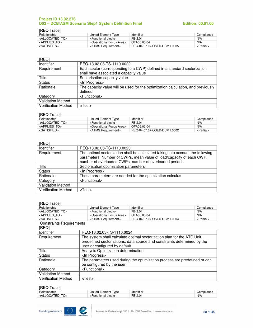
Identifier REQ-13.02.03-TS-1110.0022
Requirement Each sector (corresponding to a CWP) defined in a standard sectorization shall have associated a capacity value
Title Sectorisation capacity value
Status <In Progress>
Rationale The capacity value will be used for the optimization calculation, and previously defined
Category <Functional>
Validation Method
Verification Method <Test>
[REQ Trace] Relationship Linked Element Type Identifier Compliance
<ALLOCATED_TO> <Functional block> FB-2.04 N/A
<APPLIES_TO> <Operational Focus Area> OFA05.03.04 N/A
<SATISFIES> <ATMS Requirement> REQ-04.07.07-OSED-DCM1.0002 <Partial>
[REQ]
Identifier REQ-13.02.03-TS-1110.0023
Requirement The optimal sectorization shall be calculated taking into account the following parameters: Number of CWPs, mean value of load/capacity of each CWP, number of overloaded CWPs, number of overloaded periods
Title Sectorisation optimization parameters
Status <In Progress>
Rationale Those parameters are needed for the optimization calculus
Category <Functional>
Validation Method
Verification Method <Test>
[REQ Trace] Relationship Linked Element Type Identifier Compliance
<ALLOCATED_TO> <Functional block> FB-2.04 N/A
<APPLIES_TO> <Operational Focus Area> OFA05.03.04 N/A
<SATISFIES> <ATMS Requirement> REQ-04.07.07-OSED-DCM1.0004 <Partial>
Constraints Requirements [REQ]
Identifier REQ-13.02.03-TS-1110.0024
Requirement The system shall calculate optimal sectorization plan for the ATC Unit, predefined sectorizations, data source and constraints determined by the user or configured by default.
Title Analysis Optimization determination
Status <In Progress>
Rationale The parameters used during the optimization process are predefined or can be configured by the user
Category <Functional>
Validation Method
Verification Method <Test>
[REQ Trace] Relationship Linked Element Type Identifier Compliance
<ALLOCATED_TO> <Functional block> FB-2.04 N/A
Project ID 13.02.276 D02 – DCB/ASM Scenario Step1 System Definition Final Edition: 00.01.00
21 of 45
<APPLIES_TO> <Operational Focus Area> OFA05.03.04 N/A
<SATISFIES> <ATMS Requirement> REQ-04.07.07-OSED-DCM1.0005 <Partial>
<SATISFIES> <ATMS Requirement> REQ-04.07.07-OSED-DCM1.0015 <Partial>
[REQ]
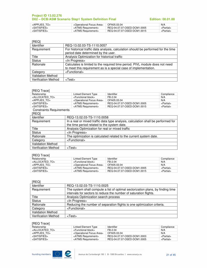
Identifier REQ-13.02.03-TS-1110.0057
Requirement For historical traffic data analysis, calculation should be performed for the time period date determined by the user.
Title Analysis Optimization for historical traffic
Status <In Progress>
Rationale Calculates is limited to the required time period. PIVL module does not need to meet this requirement as is a special case of implementation.
Category <Functional>
Validation Method
Verification Method <Test>
[REQ Trace] Relationship Linked Element Type Identifier Compliance <ALLOCATED_TO> <Functional block> FB-2.04 N/A
<APPLIES_TO> <Operational Focus Area> OFA05.03.04 N/A
<SATISFIES> <ATMS Requirement> REQ-04.07.07-OSED-DCM1.0005 <Partial>
<SATISFIES> <ATMS Requirement> REQ-04.07.07-OSED-DCM1.0015 <Partial>
Constraints Requirements [REQ]
Identifier REQ-13.02.03-TS-1110.0058
Requirement In a real or mixed traffic data type analysis, calculation shall be performed for the time period related to the system date.
Title Analysis Optimization for real or mixed traffic
Status <In Progress>
Rationale The optimization is calculated related to the current system date.
Category <Functional>
Validation Method
Verification Method <Test>
[REQ Trace] Relationship Linked Element Type Identifier Compliance
<ALLOCATED_TO> <Functional block> FB-2.04 N/A
<APPLIES_TO> <Operational Focus Area> OFA05.03.04 N/A
<SATISFIES> <ATMS Requirement> REQ-04.07.07-OSED-DCM1.0005 <Partial> <SATISFIES> <ATMS Requirement> REQ-04.07.07-OSED-DCM1.0015 <Partial>
[REQ]
Identifier REQ-13.02.03-TS-1110.0025
Requirement The system shall compute a list of optimal sectorization plans, by finding time intervals for sectors to reduce the number of saturation flights.
Title Analysis Optimization search process
Status <In Progress>
Rationale Reducing the number of separation flights is one optimization criteria.
Category <Functional>
Validation Method
Verification Method <Test>
[REQ Trace] Relationship Linked Element Type Identifier Compliance
<ALLOCATED_TO> <Functional block> FB-2.04 N/A
<APPLIES_TO> <Operational Focus Area> OFA05.03.04 N/A
<SATISFIES> <ATMS Requirement> REQ-04.07.07-OSED-DCM1.0003 <Partial>
<SATISFIES> <ATMS Requirement> REQ-04.07.07-OSED-DCM1.0005 <Partial>

Project ID 13.02.276 D02 – DCB/ASM Scenario Step1 System Definition Final Edition: 00.01.00
22 of 45
[REQ]
Identifier REQ-13.02.03-TS-1110.0026
Requirement The system shall calculate a metric for each optimal sectorization plan by finding the minimum dispersion of the occupancy factor between sectors that belongs to a predefined sectorization of every plan in a time interval.
Title Analysis Optimization combination process
Status <In Progress>
Rationale Minimum dispersion of the occupancy factor is one optimisation criteria.
Category <Functional>
Validation Method
Verification Method <Test>
[REQ Trace] Relationship Linked Element Type Identifier Compliance
<ALLOCATED_TO> <Functional block> FB-2.04 N/A
<APPLIES_TO> <Operational Focus Area> OFA05.03.04 N/A
<SATISFIES> <ATMS Requirement> REQ-04.07.07-OSED-DCM1.0003 <Partial>
<SATISFIES> <ATMS Requirement> REQ-04.07.07-OSED-DCM1.0005 <Partial>
[REQ]
Identifier REQ-13.02.03-TS-1110.0027
Requirement The system shall provide the best optimal sectorization plan and the other sectorization plans order by its metrics
Title Analysis Optimization filter process
Status <In Progress>
Rationale The order of combined metrics determines the solutions proposed.
Category <Functional>
Validation Method
Verification Method <Test>
[REQ Trace] Relationship Linked Element Type Identifier Compliance <ALLOCATED_TO> <Functional block> FB-2.04 N/A
<APPLIES_TO> <Operational Focus Area> OFA05.03.04 N/A
<SATISFIES> <ATMS Requirement> REQ-04.07.07-OSED-DCM1.0003 <Partial>
<SATISFIES> <ATMS Requirement> REQ-04.07.07-OSED-DCM1.0005 <Partial>
[REQ]
Identifier REQ-13.02.03-TS-1110.0028
Requirement The system shall store the best optimal sectorization plan for historical purposes.
Title Analysis Optimization result storage
Status <In Progress>
Rationale The calculated sectorizations are stored for further analysis in an appropriate media.
Category <Functional>
Validation Method
Verification Method <Test>
[REQ Trace] Relationship Linked Element Type Identifier Compliance
<ALLOCATED_TO> <Functional block> FB-2.04 N/A <APPLIES_TO> <Operational Focus Area> OFA05.03.04 N/A
<SATISFIES> <ATMS Requirement> REQ-04.07.07-OSED-DCM1.0019 <Partial>
[REQ]
Identifier REQ-13.02.03-TS-1110.0029
Project ID 13.02.276 D02 – DCB/ASM Scenario Step1 System Definition Final Edition: 00.01.00
23 of 45
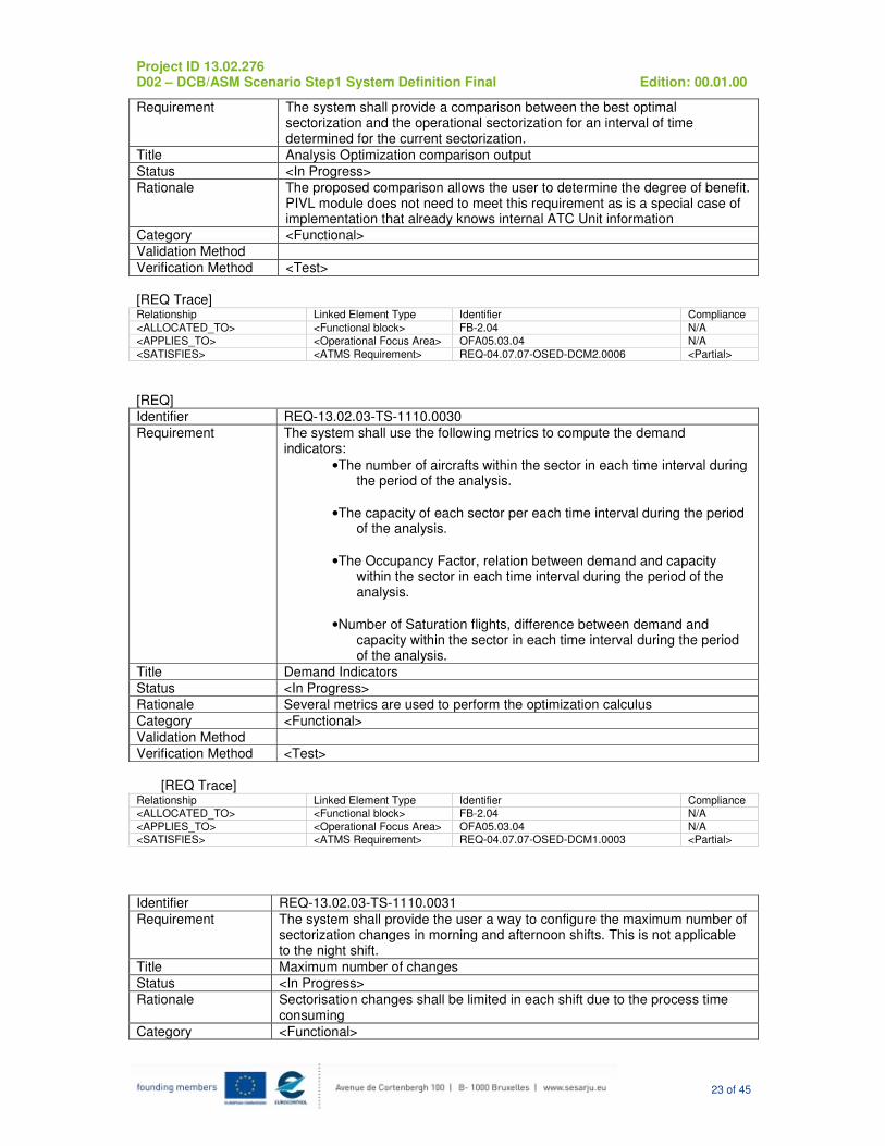
Requirement The system shall provide a comparison between the best optimal sectorization and the operational sectorization for an interval of time determined for the current sectorization.
Title Analysis Optimization comparison output
Status <In Progress>
Rationale The proposed comparison allows the user to determine the degree of benefit. PIVL module does not need to meet this requirement as is a special case of implementation that already knows internal ATC Unit information
Category <Functional>
Validation Method
Verification Method <Test>
[REQ Trace] Relationship Linked Element Type Identifier Compliance
<ALLOCATED_TO> <Functional block> FB-2.04 N/A
<APPLIES_TO> <Operational Focus Area> OFA05.03.04 N/A
<SATISFIES> <ATMS Requirement> REQ-04.07.07-OSED-DCM2.0006 <Partial>
[REQ]
Identifier REQ-13.02.03-TS-1110.0030
Requirement The system shall use the following metrics to compute the demand indicators:
•The number of aircrafts within the sector in each time interval during the period of the analysis.
•The capacity of each sector per each time interval during the period of the analysis.
•The Occupancy Factor, relation between demand and capacity within the sector in each time interval during the period of the analysis.
•Number of Saturation flights, difference between demand and capacity within the sector in each time interval during the period of the analysis.
Title Demand Indicators
Status <In Progress>
Rationale Several metrics are used to perform the optimization calculus
Category <Functional>
Validation Method
Verification Method <Test>
[REQ Trace]
Relationship Linked Element Type Identifier Compliance
<ALLOCATED_TO> <Functional block> FB-2.04 N/A
<APPLIES_TO> <Operational Focus Area> OFA05.03.04 N/A <SATISFIES> <ATMS Requirement> REQ-04.07.07-OSED-DCM1.0003 <Partial>
Identifier REQ-13.02.03-TS-1110.0031
Requirement The system shall provide the user a way to configure the maximum number of sectorization changes in morning and afternoon shifts. This is not applicable to the night shift.
Title Maximum number of changes
Status <In Progress>
Rationale Sectorisation changes shall be limited in each shift due to the process time consuming
Category <Functional>
Project ID 13.02.276 D02 – DCB/ASM Scenario Step1 System Definition Final Edition: 00.01.00
24 of 45
Validation Method
Verification Method <Test>
[REQ Trace]
Relationship Linked Element Type Identifier Compliance
<ALLOCATED_TO> <Functional block> FB-2.04 N/A
<APPLIES_TO> <Operational Focus Area> OFA05.03.04 N/A <SATISFIES> <ATMS Requirement> REQ-04.07.07-OSED-DCM1.0007 <Partial>
[REQ]
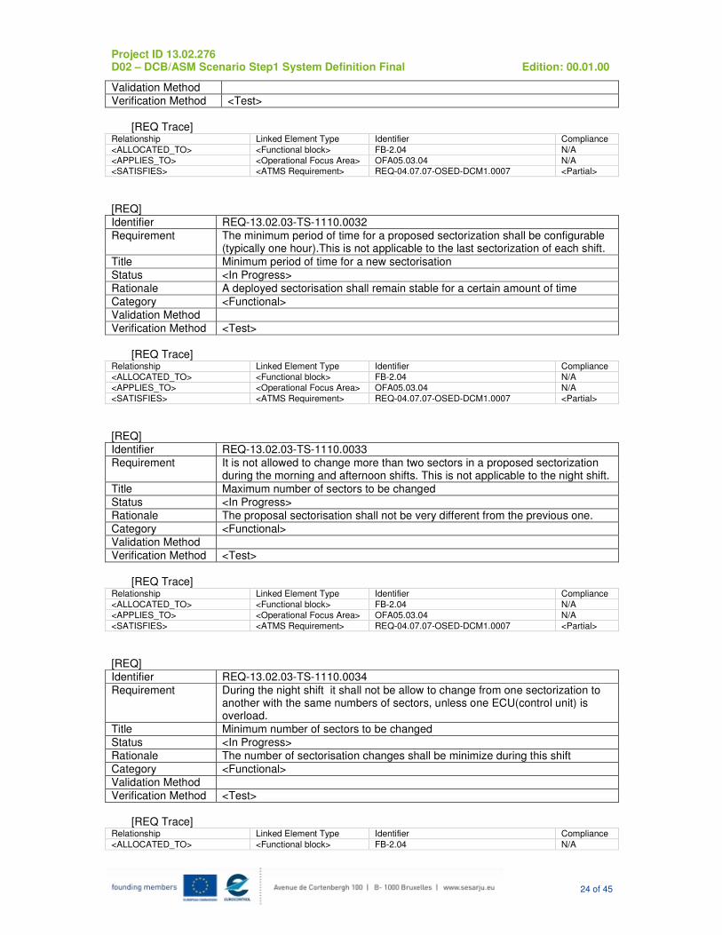
Identifier REQ-13.02.03-TS-1110.0032
Requirement The minimum period of time for a proposed sectorization shall be configurable (typically one hour).This is not applicable to the last sectorization of each shift.
Title Minimum period of time for a new sectorisation
Status <In Progress>
Rationale A deployed sectorisation shall remain stable for a certain amount of time
Category <Functional>
Validation Method
Verification Method <Test>
[REQ Trace]
Relationship Linked Element Type Identifier Compliance
<ALLOCATED_TO> <Functional block> FB-2.04 N/A
<APPLIES_TO> <Operational Focus Area> OFA05.03.04 N/A
<SATISFIES> <ATMS Requirement> REQ-04.07.07-OSED-DCM1.0007 <Partial>
[REQ]
Identifier REQ-13.02.03-TS-1110.0033
Requirement It is not allowed to change more than two sectors in a proposed sectorization during the morning and afternoon shifts. This is not applicable to the night shift.
Title Maximum number of sectors to be changed
Status <In Progress>
Rationale The proposal sectorisation shall not be very different from the previous one.
Category <Functional>
Validation Method
Verification Method <Test>
[REQ Trace]
Relationship Linked Element Type Identifier Compliance
<ALLOCATED_TO> <Functional block> FB-2.04 N/A
<APPLIES_TO> <Operational Focus Area> OFA05.03.04 N/A
<SATISFIES> <ATMS Requirement> REQ-04.07.07-OSED-DCM1.0007 <Partial>
[REQ]
Identifier REQ-13.02.03-TS-1110.0034
Requirement During the night shift it shall not be allow to change from one sectorization to another with the same numbers of sectors, unless one ECU(control unit) is overload.
Title Minimum number of sectors to be changed
Status <In Progress>
Rationale The number of sectorisation changes shall be minimize during this shift
Category <Functional>
Validation Method
Verification Method <Test>
[REQ Trace]
Relationship Linked Element Type Identifier Compliance
<ALLOCATED_TO> <Functional block> FB-2.04 N/A
Project ID 13.02.276 D02 – DCB/ASM Scenario Step1 System Definition Final Edition: 00.01.00
25 of 45
<APPLIES_TO> <Operational Focus Area> OFA05.03.04 N/A
<SATISFIES> <ATMS Requirement> REQ-04.07.07-OSED-DCM1.0007 <Partial>
[REQ]
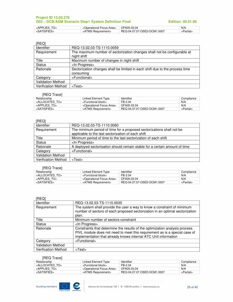
Identifier REQ-13.02.03-TS-1110.0059
Requirement The maximum number of sectorization changes shall not be configurable at night shift
Title Maximum number of changes in night shift
Status <In Progress>
Rationale Sectorization changes shall be limited in each shift due to the process time consuming
Category <Functional>
Validation Method
Verification Method <Test>
[REQ Trace]
Relationship Linked Element Type Identifier Compliance
<ALLOCATED_TO> <Functional block> FB-2.04 N/A
<APPLIES_TO> <Operational Focus Area> OFA05.03.04 N/A <SATISFIES> <ATMS Requirement> REQ-04.07.07-OSED-DCM1.0007 <Partial>
[REQ]
Identifier REQ-13.02.03-TS-1110.0060
Requirement The minimum period of time for a proposed sectorizations shall not be applicable to the last sectorization of each shift
Title Minimum period of time to the last sectorization of each shift
Status <In Progress>
Rationale A deployed sectorisation should remain stable for a certain amount of time
Category <Functional>
Validation Method
Verification Method <Test>
[REQ Trace]
Relationship Linked Element Type Identifier Compliance
<ALLOCATED_TO> <Functional block> FB-2.04 N/A
<APPLIES_TO> <Operational Focus Area> OFA05.03.04 N/A
<SATISFIES> <ATMS Requirement> REQ-04.07.07-OSED-DCM1.0007 <Partial>
[REQ]
Identifier REQ-13.02.03-TS-1110.0035
Requirement The system shall provide the user a way to know a constraint of minimum number of sectors of each proposed sectorization in an optimal sectorization plan.
Title Minimum number of sectors constraint
Status <In Progress>
Rationale Constraints that determine the results of the optimization analysis process. PIVL module does not need to meet this requirement as is a special case of implementation that already knows internal ATC Unit information
Category <Functional>
Validation Method
Verification Method <Test>
[REQ Trace]
Relationship Linked Element Type Identifier Compliance
<ALLOCATED_TO> <Functional block> FB-2.04 N/A
<APPLIES_TO> <Operational Focus Area> OFA05.03.04 N/A
<SATISFIES> <ATMS Requirement> REQ-04.07.07-OSED-DCM1.0007 <Partial>
Project ID 13.02.276 D02 – DCB/ASM Scenario Step1 System Definition Final Edition: 00.01.00
26 of 45
[REQ]
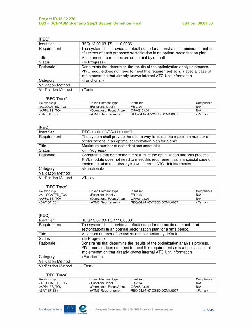
Identifier REQ-13.02.03-TS-1110.0036
Requirement The system shall provide a default setup for a constraint of minimum number of sectors of each proposed sectorization in an optimal sectorization plan.
Title Minimum number of sectors constraint by default
Status <In Progress>
Rationale Constraints that determine the results of the optimization analysis process. PIVL module does not need to meet this requirement as is a special case of implementation that already knows internal ATC Unit information
Category <Functional>
Validation Method
Verification Method <Test>
[REQ Trace]
Relationship Linked Element Type Identifier Compliance
<ALLOCATED_TO> <Functional block> FB-2.04 N/A
<APPLIES_TO> <Operational Focus Area> OFA05.03.04 N/A <SATISFIES> <ATMS Requirement> REQ-04.07.07-OSED-DCM1.0007 <Partial>
[REQ]
Identifier REQ-13.02.03-TS-1110.0037
Requirement The system shall provide the user a way to select the maximum number of sectorizations in an optimal sectorization plan for a shift.
Title Maximum number of sectorizations constraint
Status <In Progress>
Rationale Constraints that determine the results of the optimization analysis process. PIVL module does not need to meet this requirement as is a special case of implementation that already knows internal ATC Unit information
Category <Functional>
Validation Method
Verification Method <Test>
[REQ Trace]
Relationship Linked Element Type Identifier Compliance
<ALLOCATED_TO> <Functional block> FB-2.04 N/A
<APPLIES_TO> <Operational Focus Area> OFA05.03.04 N/A
<SATISFIES> <ATMS Requirement> REQ-04.07.07-OSED-DCM1.0007 <Partial>
[REQ]
Identifier REQ-13.02.03-TS-1110.0038
Requirement The system shall provide a default setup for the maximum number of sectorizations in an optimal sectorization plan for a time period.
Title Maximum number of sectorizations constraint by default
Status <In Progress>
Rationale Constraints that determine the results of the optimization analysis process. PIVL module does not need to meet this requirement as is a special case of implementation that already knows internal ATC Unit information
Category <Functional>
Validation Method
Verification Method <Test>
[REQ Trace]
Relationship Linked Element Type Identifier Compliance
<ALLOCATED_TO> <Functional block> FB-2.04 N/A
<APPLIES_TO> <Operational Focus Area> OFA05.03.04 N/A
<SATISFIES> <ATMS Requirement> REQ-04.07.07-OSED-DCM1.0007 <Partial>
Project ID 13.02.276 D02 – DCB/ASM Scenario Step1 System Definition Final Edition: 00.01.00
27 of 45
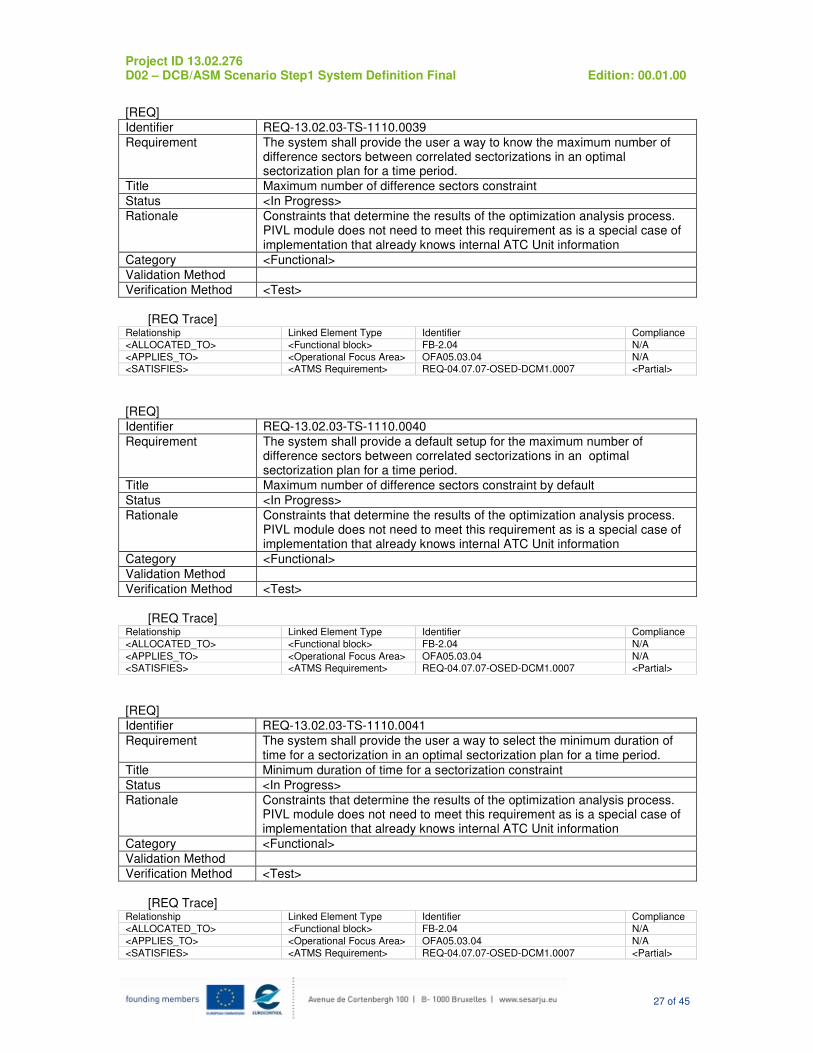
[REQ]
Identifier REQ-13.02.03-TS-1110.0039
Requirement The system shall provide the user a way to know the maximum number of difference sectors between correlated sectorizations in an optimal sectorization plan for a time period.
Title Maximum number of difference sectors constraint
Status <In Progress>
Rationale Constraints that determine the results of the optimization analysis process. PIVL module does not need to meet this requirement as is a special case of implementation that already knows internal ATC Unit information
Category <Functional>
Validation Method
Verification Method <Test>
[REQ Trace]
Relationship Linked Element Type Identifier Compliance
<ALLOCATED_TO> <Functional block> FB-2.04 N/A
<APPLIES_TO> <Operational Focus Area> OFA05.03.04 N/A <SATISFIES> <ATMS Requirement> REQ-04.07.07-OSED-DCM1.0007 <Partial>
[REQ]
Identifier REQ-13.02.03-TS-1110.0040
Requirement The system shall provide a default setup for the maximum number of difference sectors between correlated sectorizations in an optimal sectorization plan for a time period.
Title Maximum number of difference sectors constraint by default
Status <In Progress>
Rationale Constraints that determine the results of the optimization analysis process. PIVL module does not need to meet this requirement as is a special case of implementation that already knows internal ATC Unit information
Category <Functional>
Validation Method
Verification Method <Test>
[REQ Trace]
Relationship Linked Element Type Identifier Compliance
<ALLOCATED_TO> <Functional block> FB-2.04 N/A
<APPLIES_TO> <Operational Focus Area> OFA05.03.04 N/A <SATISFIES> <ATMS Requirement> REQ-04.07.07-OSED-DCM1.0007 <Partial>
[REQ]
Identifier REQ-13.02.03-TS-1110.0041
Requirement The system shall provide the user a way to select the minimum duration of time for a sectorization in an optimal sectorization plan for a time period.
Title Minimum duration of time for a sectorization constraint
Status <In Progress>
Rationale Constraints that determine the results of the optimization analysis process. PIVL module does not need to meet this requirement as is a special case of implementation that already knows internal ATC Unit information
Category <Functional>
Validation Method
Verification Method <Test>
[REQ Trace]
Relationship Linked Element Type Identifier Compliance
<ALLOCATED_TO> <Functional block> FB-2.04 N/A
<APPLIES_TO> <Operational Focus Area> OFA05.03.04 N/A
<SATISFIES> <ATMS Requirement> REQ-04.07.07-OSED-DCM1.0007 <Partial>
Project ID 13.02.276 D02 – DCB/ASM Scenario Step1 System Definition Final Edition: 00.01.00
28 of 45
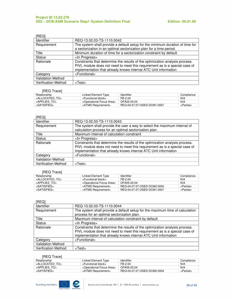
[REQ]
Identifier REQ-13.02.03-TS-1110.0042
Requirement The system shall provide a default setup for the minimum duration of time for a sectorization in an optimal sectorization plan for a time period.
Title Minimum duration of time for a sectorization constraint by default
Status <In Progress>
Rationale Constraints that determine the results of the optimization analysis process. PIVL module does not need to meet this requirement as is a special case of implementation that already knows internal ATC Unit information
Category <Functional>
Validation Method
Verification Method <Test>
[REQ Trace]
Relationship Linked Element Type Identifier Compliance
<ALLOCATED_TO> <Functional block> FB-2.04 N/A
<APPLIES_TO> <Operational Focus Area> OFA05.03.04 N/A <SATISFIES> <ATMS Requirement> REQ-04.07.07-OSED-DCM1.0007 <Partial>
[REQ]
Identifier REQ-13.02.03-TS-1110.0043
Requirement The system shall provide the user a way to select the maximum interval of calculation process for an optimal sectorization plan.
Title Maximum interval of calculation constraint
Status <In Progress>
Rationale Constraints that determine the results of the optimization analysis process. PIVL module does not need to meet this requirement as is a special case of implementation that already knows internal ATC Unit information
Category <Functional>
Validation Method
Verification Method <Test>
[REQ Trace]
Relationship Linked Element Type Identifier Compliance
<ALLOCATED_TO> <Functional block> FB-2.04 N/A
<APPLIES_TO> <Operational Focus Area> OFA05.03.04 N/A
<SATISFIES> <ATMS Requirement> REQ-04.07.07-OSED-DCM2.0004 <Partial>
<SATISFIES> <ATMS Requirement> REQ-04.07.07-OSED-DCM1.0007 <Partial>
[REQ]
Identifier REQ-13.02.03-TS-1110.0044
Requirement The system shall provide a default setup for the maximum time of calculation process for an optimal sectorization plan.
Title Maximum interval of calculation constraint by default
Status <In Progress>
Rationale Constraints that determine the results of the optimization analysis process. PIVL module does not need to meet this requirement as is a special case of implementation that already knows internal ATC Unit information
Category <Functional>
Validation Method
Verification Method <Test>
[REQ Trace]
Relationship Linked Element Type Identifier Compliance
<ALLOCATED_TO> <Functional block> FB-2.04 N/A
<APPLIES_TO> <Operational Focus Area> OFA05.03.04 N/A
<SATISFIES> <ATMS Requirement> REQ-04.07.07-OSED-DCM2.0004 <Partial>
Project ID 13.02.276 D02 – DCB/ASM Scenario Step1 System Definition Final Edition: 00.01.00
29 of 45
<SATISFIES> <ATMS Requirement> REQ-04.07.07-OSED-DCM1.0007 <Partial>
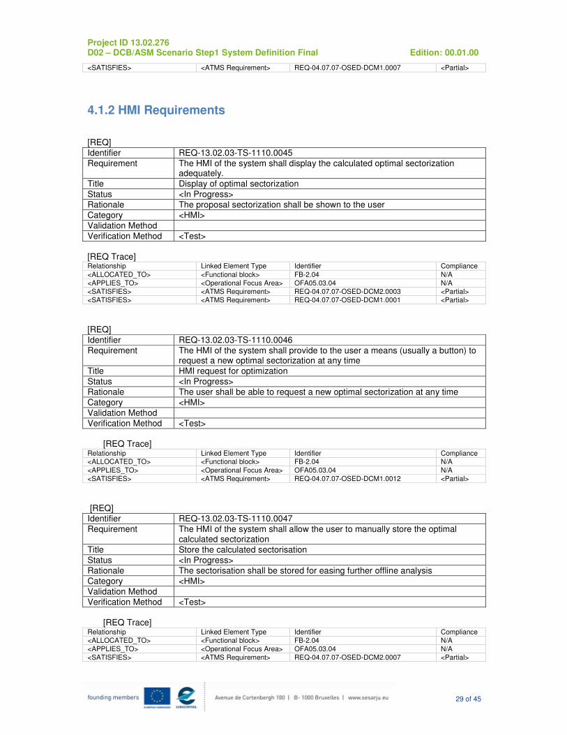
4.1.2 HMI Requirements
[REQ]
Identifier REQ-13.02.03-TS-1110.0045
Requirement The HMI of the system shall display the calculated optimal sectorization adequately.
Title Display of optimal sectorization
Status <In Progress>
Rationale The proposal sectorization shall be shown to the user
Category <HMI>
Validation Method
Verification Method <Test>
[REQ Trace] Relationship Linked Element Type Identifier Compliance
<ALLOCATED_TO> <Functional block> FB-2.04 N/A
<APPLIES_TO> <Operational Focus Area> OFA05.03.04 N/A
<SATISFIES> <ATMS Requirement> REQ-04.07.07-OSED-DCM2.0003 <Partial>
<SATISFIES> <ATMS Requirement> REQ-04.07.07-OSED-DCM1.0001 <Partial>
[REQ]
Identifier REQ-13.02.03-TS-1110.0046
Requirement The HMI of the system shall provide to the user a means (usually a button) to request a new optimal sectorization at any time
Title HMI request for optimization
Status <In Progress>
Rationale The user shall be able to request a new optimal sectorization at any time
Category <HMI>
Validation Method
Verification Method <Test>
[REQ Trace]
Relationship Linked Element Type Identifier Compliance <ALLOCATED_TO> <Functional block> FB-2.04 N/A
<APPLIES_TO> <Operational Focus Area> OFA05.03.04 N/A
<SATISFIES> <ATMS Requirement> REQ-04.07.07-OSED-DCM1.0012 <Partial>
[REQ] Identifier REQ-13.02.03-TS-1110.0047
Requirement The HMI of the system shall allow the user to manually store the optimal calculated sectorization
Title Store the calculated sectorisation
Status <In Progress>
Rationale The sectorisation shall be stored for easing further offline analysis
Category <HMI>
Validation Method
Verification Method <Test>
[REQ Trace]
Relationship Linked Element Type Identifier Compliance
<ALLOCATED_TO> <Functional block> FB-2.04 N/A
<APPLIES_TO> <Operational Focus Area> OFA05.03.04 N/A
<SATISFIES> <ATMS Requirement> REQ-04.07.07-OSED-DCM2.0007 <Partial>

Project ID 13.02.276 D02 – DCB/ASM Scenario Step1 System Definition Final Edition: 00.01.00
30 of 45
[REQ]
Identifier REQ-13.02.03-TS-1110.0048
Requirement The HMI of the system shall be able to display to the user any previously stored optimal sectorization.
Title Display stored sectorizations
Status <In Progress>
Rationale The stored sectorizations shall be displayed to ease the offline analysis
Category <HMI>
Validation Method
Verification Method <Test>
[REQ Trace] Relationship Linked Element Type Identifier Compliance
<ALLOCATED_TO> <Functional block> FB-2.04 N/A
<APPLIES_TO> <Operational Focus Area> OFA05.03.04 N/A
<SATISFIES> <ATMS Requirement> REQ-04.07.07-OSED-DCM1.0018 <Partial>
[REQ]
Identifier REQ-13.02.03-TS-1110.0049
Requirement The HMI of the system shall provide to the user a means for selecting any of the previously stored optimal sectorizations
Title Select a stored sectorisation
Status <In Progress>
Rationale The user can perform, in this way, an offline analysis by comparing the different stored sectorisations
Category <HMI>
Validation Method
Verification Method <Test>
[REQ Trace] Relationship Linked Element Type Identifier Compliance
<ALLOCATED_TO> <Functional block> FB-2.04 N/A <APPLIES_TO> <Operational Focus Area> OFA05.03.04 N/A
<SATISFIES> <ATMS Requirement> REQ-04.07.07-OSED-DCM1.0018 <Partial>
<SATISFIES> <ATMS Requirement> REQ-04.07.07-OSED-DCM2.0006 <Partial>
[REQ]
Identifier REQ-13.02.03-TS-1110.0050
Requirement The HMI of the system shall provide to the user a means to modify manually any of the previously stored optimal sectorizations
Title Modify a stored sectorization
Status <In Progress>
Rationale The user shall be able to test small changes on a previously stored sectorization. PIVL module does not need to meet this requirement as is a special case of implementation that already knows internal ATC Unit information
Category <HMI>
Validation Method
Verification Method <Test>
[REQ Trace] Relationship Linked Element Type Identifier Compliance
<ALLOCATED_TO> <Functional block> FB-2.04 N/A
<APPLIES_TO> <Operational Focus Area> OFA05.03.04 N/A
<SATISFIES> <ATMS Requirement> REQ-04.07.07-OSED-DCM2.0009 <Partial>
<SATISFIES> <ATMS Requirement> REQ-04.07.07-OSED-DCM1.0014 <Partial>

Project ID 13.02.276 D02 – DCB/ASM Scenario Step1 System Definition Final Edition: 00.01.00
31 of 45
[REQ]
Identifier REQ-13.02.03-TS-1110.0051
Requirement The HMI of the system shall display charts showing computed demand indicator for each sector of each predefined sectorization in every time interval of the time period for which analysis will be performed.
Title Demand Indicators per Sector data chart output
Status <In Progress>
Rationale System output for demand indicators calculated in data acquisition by graphical chart. PIVL module does not need to meet this requirement as is a special case of implementation that already knows internal ATC Unit information
Category <HMI>
Validation Method
Verification Method <Test>
[REQ Trace] Relationship Linked Element Type Identifier Compliance
<ALLOCATED_TO> <Functional block> FB-2.04 N/A
<APPLIES_TO> <Operational Focus Area> OFA05.03.04 N/A <SATISFIES> <ATMS Requirement> REQ-04.07.07-OSED-DCM2.0001 <Partial>
[REQ]
Identifier REQ-13.02.03-TS-1110.0052
Requirement The HMI of the system shall display tables showing computed demand indicator for each sector of each predefined sectorization in every time interval of the time period for which analysis will be performed.
Title Demand Indicator per Sector data table output
Status <In Progress>
Rationale System output for demand indicators calculated in data acquisition by Property Value table. PIVL module does not need to meet this requirement as is a special case of implementation that already knows internal ATC Unit information
Category <HMI>
Validation Method
Verification Method <Test>
[REQ Trace] Relationship Linked Element Type Identifier Compliance
<ALLOCATED_TO> <Functional block> FB-2.04 N/A <APPLIES_TO> <Operational Focus Area> OFA05.03.04 N/A
<SATISFIES> <ATMS Requirement> REQ-04.07.07-OSED-DCM2.0002 <Partial>
[REQ]
Identifier REQ-13.02.03-TS-1110.0053
Requirement The HMI of the system shall inform the user about errors detected in the user input data process by error warnings.
Title Error output.
Status <In Progress>
Rationale System output for errors detected. PIVL module does not need to meet this requirement as is a special case of implementation that already knows internal ATC Unit information
Category <HMI>
Validation Method
Verification Method <Test>
[REQ Trace] Relationship Linked Element Type Identifier Compliance
<ALLOCATED_TO> <Functional block> FB-2.04 N/A
<APPLIES_TO> <Operational Focus Area> OFA05.03.04 N/A
Project ID 13.02.276 D02 – DCB/ASM Scenario Step1 System Definition Final Edition: 00.01.00
32 of 45
<SATISFIES> <ATMS Requirement> REQ-04.07.07-OSED-DCM2.0008 <Partial>
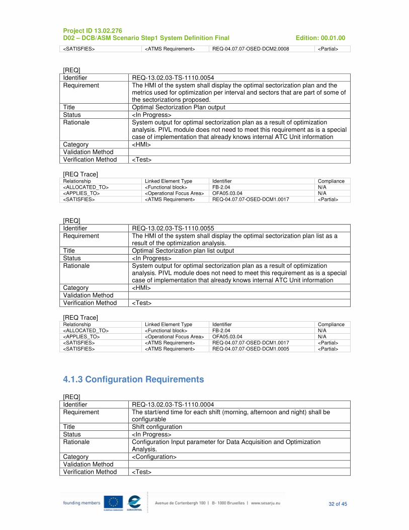
[REQ]
Identifier REQ-13.02.03-TS-1110.0054
Requirement The HMI of the system shall display the optimal sectorization plan and the metrics used for optimization per interval and sectors that are part of some of the sectorizations proposed.
Title Optimal Sectorization Plan output
Status <In Progress>
Rationale System output for optimal sectorization plan as a result of optimization analysis. PIVL module does not need to meet this requirement as is a special case of implementation that already knows internal ATC Unit information
Category <HMI>
Validation Method
Verification Method <Test>
[REQ Trace] Relationship Linked Element Type Identifier Compliance
<ALLOCATED_TO> <Functional block> FB-2.04 N/A <APPLIES_TO> <Operational Focus Area> OFA05.03.04 N/A
<SATISFIES> <ATMS Requirement> REQ-04.07.07-OSED-DCM1.0017 <Partial>
[REQ]
Identifier REQ-13.02.03-TS-1110.0055
Requirement The HMI of the system shall display the optimal sectorization plan list as a result of the optimization analysis.
Title Optimal Sectorization plan list output
Status <In Progress>
Rationale System output for optimal sectorization plan as a result of optimization analysis. PIVL module does not need to meet this requirement as is a special case of implementation that already knows internal ATC Unit information
Category <HMI>
Validation Method
Verification Method <Test>
[REQ Trace] Relationship Linked Element Type Identifier Compliance
<ALLOCATED_TO> <Functional block> FB-2.04 N/A
<APPLIES_TO> <Operational Focus Area> OFA05.03.04 N/A
<SATISFIES> <ATMS Requirement> REQ-04.07.07-OSED-DCM1.0017 <Partial>
<SATISFIES> <ATMS Requirement> REQ-04.07.07-OSED-DCM1.0005 <Partial>
4.1.3 Configuration Requirements [REQ]
Identifier REQ-13.02.03-TS-1110.0004
Requirement The start/end time for each shift (morning, afternoon and night) shall be configurable
Title Shift configuration
Status <In Progress>
Rationale Configuration Input parameter for Data Acquisition and Optimization Analysis.
Category <Configuration>
Validation Method
Verification Method <Test>

Project ID 13.02.276 D02 – DCB/ASM Scenario Step1 System Definition Final Edition: 00.01.00
33 of 45
[REQ Trace] Relationship Linked Element Type Identifier Compliance
<ALLOCATED_TO> <Functional block> FB-2.04 N/A
<APPLIES_TO> <Operational Focus Area> OFA05.03.04 N/A <SATISFIES> <ATMS Requirement> REQ-04.07.07-OSED-DCM1.0011 <Partial>
<SATISFIES> <ATMS Requirement> REQ-04.07.07-OSED-DCM1.0006 <Partial>
[REQ]
Identifier REQ-13.02.03-TS-1110.0005
Requirement The system shall provide a default setup of the start/end time for each shift: Morning, Afternoon or Night.
Title Default configuration for Time Period
Status <In Progress>
Rationale Configuration Input parameter for Data Acquisition and Optimization Analysis. PIVL module does not need to meet this requirement as is a special case of implementation that already knows internal ATC Unit information.
Category <Configuration>
Validation Method
Verification Method <Test>
[REQ Trace]
Relationship Linked Element Type Identifier Compliance
<ALLOCATED_TO> <Functional block> FB-2.04 N/A <APPLIES_TO> <Operational Focus Area> OFA05.03.04 N/A
<SATISFIES> <ATMS Requirement> REQ-04.07.07-OSED-DCM1.0011 <Partial>
[REQ]
Identifier REQ-13.02.03-TS-1110.0009
Requirement The system shall provide a way to configure communication setup with the ATC-System to which it is connected.
Title ATC-System communication configuration
Status <In Progress>
Rationale Parameters used by the communication are TCP/IP protocol and format determined by the ATC Unit. PIVL module does not need to meet this requirement as is a special case of implementation that already knows internal ATC Unit information
Category <Configuration>
Validation Method
Verification Method <Test>
[REQ Trace]
Relationship Linked Element Type Identifier Compliance
<ALLOCATED_TO> <Functional block> FB-2.04 N/A
<APPLIES_TO> <Operational Focus Area> OFA05.03.04 N/A
<SATISFIES> <ATMS Requirement> REQ-04.07.07-OSED-DCM1.0008 <Partial>
[REQ]
Identifier REQ-13.02.03-TS-1110.0010
Requirement The system shall provide a way to configure communication setup with the Data Base to which it is connected.
Title Data Base communication configuration
Status <In Progress>
Rationale Parameters used by the communication are TCP/IP protocol and format determined by the data Base. PIVL module does not need to meet this requirement as is a special case of implementation that already knows internal ATC Unit information
Category <Configuration>
Project ID 13.02.276 D02 – DCB/ASM Scenario Step1 System Definition Final Edition: 00.01.00
34 of 45
Validation Method
Verification Method <Test>
[REQ Trace]
Relationship Linked Element Type Identifier Compliance
<ALLOCATED_TO> <Functional block> FB-2.04 N/A
<APPLIES_TO> <Operational Focus Area> OFA05.03.04 N/A <SATISFIES> <ATMS Requirement> REQ-04.07.07-OSED-DCM1.0008 <Partial>
[REQ]
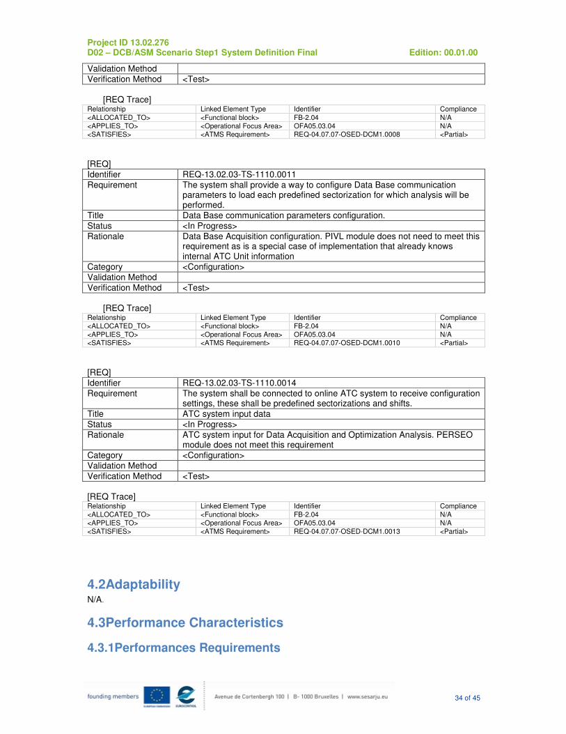
Identifier REQ-13.02.03-TS-1110.0011
Requirement The system shall provide a way to configure Data Base communication parameters to load each predefined sectorization for which analysis will be performed.
Title Data Base communication parameters configuration.
Status <In Progress>
Rationale Data Base Acquisition configuration. PIVL module does not need to meet this requirement as is a special case of implementation that already knows internal ATC Unit information
Category <Configuration>
Validation Method
Verification Method <Test>
[REQ Trace]
Relationship Linked Element Type Identifier Compliance
<ALLOCATED_TO> <Functional block> FB-2.04 N/A
<APPLIES_TO> <Operational Focus Area> OFA05.03.04 N/A <SATISFIES> <ATMS Requirement> REQ-04.07.07-OSED-DCM1.0010 <Partial>
[REQ]
Identifier REQ-13.02.03-TS-1110.0014
Requirement The system shall be connected to online ATC system to receive configuration settings, these shall be predefined sectorizations and shifts.
Title ATC system input data
Status <In Progress>
Rationale ATC system input for Data Acquisition and Optimization Analysis. PERSEO module does not meet this requirement
Category <Configuration>
Validation Method
Verification Method <Test>
[REQ Trace] Relationship Linked Element Type Identifier Compliance
<ALLOCATED_TO> <Functional block> FB-2.04 N/A
<APPLIES_TO> <Operational Focus Area> OFA05.03.04 N/A
<SATISFIES> <ATMS Requirement> REQ-04.07.07-OSED-DCM1.0013 <Partial>
4.2Adaptability N/A.
4.3Performance Characteristics
4.3.1Performances Requirements

Project ID 13.02.276 D02 – DCB/ASM Scenario Step1 System Definition Final Edition: 00.01.00
35 of 45
[REQ]
Identifier REQ-13.02.03-TS-1130.0001
Requirement The performances of the system take into account the following parameters: -The number of predefined sectorizations -The number of flights processed in the system -The duration of the shifts
Title Optimal Sectorization Plan performance
Status <In Progress>
Rationale . PIVL module does not need to meet this requirement as is a special case of implementation that already knows internal ATC Unit information
Category <Performance>
Validation Method
Verification Method <Test>
[REQ Trace] Relationship Linked Element Type Identifier Compliance
<ALLOCATED_TO> <Functional block> FB-2.04 N/A
<APPLIES_TO> <Operational Focus Area> OFA05.03.04 N/A
<SATISFIES> <ATMS Requirement> REQ-04.07.07-OSED-DCM2.0004 <Partial>
4.4Safety & Security N/A
4.5Maintainability N/A
4.6Reliability
Reliability encompasses robustness to abnormal operating conditions.
4.6.1Reliability Requirements
[REQ]
Identifier REQ-13.02.03-TS-1160.0001
Requirement The system shall detect format errors on the input data from the ATC System
Title Detection of input data errors from the ATC System
Status <In Progress>
Rationale An error in input data shall be detected to avoid further processing on those data. PIVL module does not need to meet this requirement as is a special case of implementation that already knows internal ATC Unit information
Category <Reliability>
Validation Method
Verification Method <Test>
[REQ Trace] Relationship Linked Element Type Identifier Compliance
<ALLOCATED_TO> <Functional block> FB-2.04 N/A
<APPLIES_TO> <Operational Focus Area> OFA05.03.04 N/A <SATISFIES> <ATMS Requirement> REQ-04.07.07-OSED-DCM2.0008 <Partial>
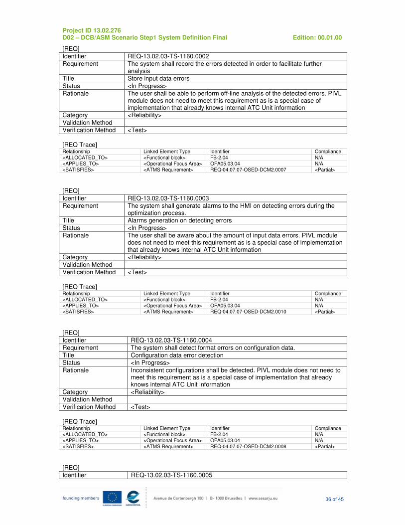
Project ID 13.02.276 D02 – DCB/ASM Scenario Step1 System Definition Final Edition: 00.01.00
36 of 45
[REQ]
Identifier REQ-13.02.03-TS-1160.0002
Requirement The system shall record the errors detected in order to facilitate further analysis
Title Store input data errors
Status <In Progress>
Rationale The user shall be able to perform off-line analysis of the detected errors. PIVL module does not need to meet this requirement as is a special case of implementation that already knows internal ATC Unit information
Category <Reliability>
Validation Method
Verification Method <Test>
[REQ Trace] Relationship Linked Element Type Identifier Compliance
<ALLOCATED_TO> <Functional block> FB-2.04 N/A
<APPLIES_TO> <Operational Focus Area> OFA05.03.04 N/A
<SATISFIES> <ATMS Requirement> REQ-04.07.07-OSED-DCM2.0007 <Partial>
[REQ]
Identifier REQ-13.02.03-TS-1160.0003
Requirement The system shall generate alarms to the HMI on detecting errors during the optimization process.
Title Alarms generation on detecting errors
Status <In Progress>
Rationale The user shall be aware about the amount of input data errors. PIVL module does not need to meet this requirement as is a special case of implementation that already knows internal ATC Unit information
Category <Reliability>
Validation Method
Verification Method <Test>
[REQ Trace] Relationship Linked Element Type Identifier Compliance
<ALLOCATED_TO> <Functional block> FB-2.04 N/A
<APPLIES_TO> <Operational Focus Area> OFA05.03.04 N/A
<SATISFIES> <ATMS Requirement> REQ-04.07.07-OSED-DCM2.0010 <Partial>
[REQ]
Identifier REQ-13.02.03-TS-1160.0004
Requirement The system shall detect format errors on configuration data.
Title Configuration data error detection
Status <In Progress>
Rationale Inconsistent configurations shall be detected. PIVL module does not need to meet this requirement as is a special case of implementation that already knows internal ATC Unit information
Category <Reliability>
Validation Method
Verification Method <Test>
[REQ Trace] Relationship Linked Element Type Identifier Compliance
<ALLOCATED_TO> <Functional block> FB-2.04 N/A
<APPLIES_TO> <Operational Focus Area> OFA05.03.04 N/A
<SATISFIES> <ATMS Requirement> REQ-04.07.07-OSED-DCM2.0008 <Partial>
[REQ]
Identifier REQ-13.02.03-TS-1160.0005

Project ID 13.02.276 D02 – DCB/ASM Scenario Step1 System Definition Final Edition: 00.01.00
37 of 45
Requirement The system shall detect format errors on user input data.
Title User input data error detection
Status <In Progress>
Rationale These alarms allow reliable use for intended users. PIVL module does not need to meet this requirement as is a special case of implementation that already knows internal ATC Unit information
Category <Reliability>
Validation Method
Verification Method <Test>
[REQ Trace] Relationship Linked Element Type Identifier Compliance <ALLOCATED_TO> <Functional block> FB-2.04 N/A
<APPLIES_TO> <Operational Focus Area> OFA05.03.04 N/A
<SATISFIES> <ATMS Requirement> REQ-04.07.07-OSED-DCM2.0008 <Partial>
[REQ]
Identifier REQ-13.02.03-TS-1160.0006
Requirement The system shall record all the alarms generated in order to facilitate further analysis
Title Record generated alarms
Status <In Progress>
Rationale The alarms generated shall be used for further analysis. PIVL module does not need to meet this requirement as is a special case of implementation that already knows internal ATC Unit information
Category <Reliability>
Validation Method
Verification Method <Test>
[REQ Trace] Relationship Linked Element Type Identifier Compliance
<ALLOCATED_TO> <Functional block> FB-2.04 N/A <APPLIES_TO> <Operational Focus Area> OFA05.03.04 N/A
<SATISFIES> <ATMS Requirement> REQ-04.07.07-OSED-DCM2.0007 <Partial>
[REQ]
Identifier REQ-13.02.03-TS-1160.0007
Requirement The system shall provide a media (likely a service) to deliver the recorded alarms and errors information to external systems requests
Title Deliver recorded alarm and error information
Status <In Progress> Rationale This information could be used by other systems for further analysis. PIVL
module does not need to meet this requirement as is a special case of implementation that already knows internal ATC Unit information
Category <Reliability>
Validation Method
Verification Method <Test>
[REQ Trace] Relationship Linked Element Type Identifier Compliance
<ALLOCATED_TO> <Functional block> FB-2.04 N/A
<APPLIES_TO> <Operational Focus Area> OFA05.03.04 N/A
<SATISFIES> <ATMS Requirement> REQ-04.07.07-OSED-DCM2.0008 <Partial>
<SATISFIES> <ATMS Requirement> REQ-04.07.07-OSED-DCM2.0007 <Partial>
[REQ]
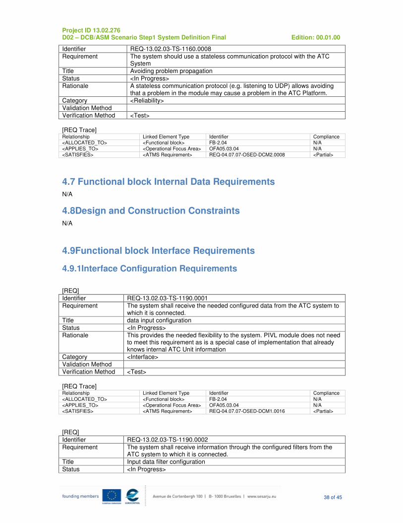
Project ID 13.02.276 D02 – DCB/ASM Scenario Step1 System Definition Final Edition: 00.01.00
38 of 45
Identifier REQ-13.02.03-TS-1160.0008
Requirement The system should use a stateless communication protocol with the ATC System
Title Avoiding problem propagation
Status <In Progress>
Rationale A stateless communication protocol (e.g. listening to UDP) allows avoiding that a problem in the module may cause a problem in the ATC Platform.
Category <Reliability>
Validation Method
Verification Method <Test>
[REQ Trace] Relationship Linked Element Type Identifier Compliance <ALLOCATED_TO> <Functional block> FB-2.04 N/A
<APPLIES_TO> <Operational Focus Area> OFA05.03.04 N/A
<SATISFIES> <ATMS Requirement> REQ-04.07.07-OSED-DCM2.0008 <Partial>
4.7 Functional block Internal Data Requirements
N/A
4.8Design and Construction Constraints
N/A
4.9Functional block Interface Requirements
4.9.1Interface Configuration Requirements
[REQ]
Identifier REQ-13.02.03-TS-1190.0001
Requirement The system shall receive the needed configured data from the ATC system to which it is connected.
Title data input configuration
Status <In Progress>
Rationale This provides the needed flexibility to the system. PIVL module does not need to meet this requirement as is a special case of implementation that already knows internal ATC Unit information
Category <Interface>
Validation Method
Verification Method <Test>
[REQ Trace] Relationship Linked Element Type Identifier Compliance
<ALLOCATED_TO> <Functional block> FB-2.04 N/A
<APPLIES_TO> <Operational Focus Area> OFA05.03.04 N/A <SATISFIES> <ATMS Requirement> REQ-04.07.07-OSED-DCM1.0016 <Partial>
[REQ]
Identifier REQ-13.02.03-TS-1190.0002
Requirement The system shall receive information through the configured filters from the ATC system to which it is connected.
Title Input data filter configuration
Status <In Progress>
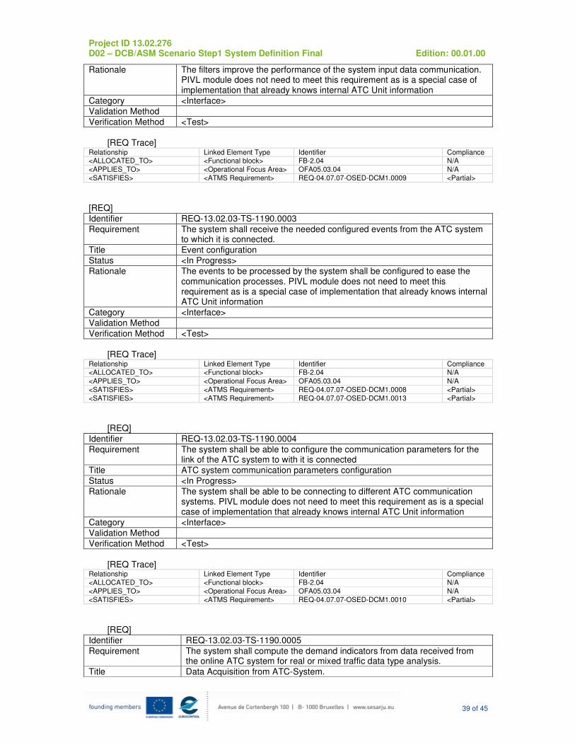
Project ID 13.02.276 D02 – DCB/ASM Scenario Step1 System Definition Final Edition: 00.01.00
39 of 45
Rationale The filters improve the performance of the system input data communication. PIVL module does not need to meet this requirement as is a special case of implementation that already knows internal ATC Unit information
Category <Interface>
Validation Method
Verification Method <Test>
[REQ Trace]
Relationship Linked Element Type Identifier Compliance <ALLOCATED_TO> <Functional block> FB-2.04 N/A
<APPLIES_TO> <Operational Focus Area> OFA05.03.04 N/A
<SATISFIES> <ATMS Requirement> REQ-04.07.07-OSED-DCM1.0009 <Partial>
[REQ]
Identifier REQ-13.02.03-TS-1190.0003
Requirement The system shall receive the needed configured events from the ATC system to which it is connected.
Title Event configuration
Status <In Progress>
Rationale The events to be processed by the system shall be configured to ease the communication processes. PIVL module does not need to meet this requirement as is a special case of implementation that already knows internal ATC Unit information
Category <Interface>
Validation Method
Verification Method <Test>
[REQ Trace]
Relationship Linked Element Type Identifier Compliance <ALLOCATED_TO> <Functional block> FB-2.04 N/A
<APPLIES_TO> <Operational Focus Area> OFA05.03.04 N/A
<SATISFIES> <ATMS Requirement> REQ-04.07.07-OSED-DCM1.0008 <Partial>
<SATISFIES> <ATMS Requirement> REQ-04.07.07-OSED-DCM1.0013 <Partial>
[REQ]
Identifier REQ-13.02.03-TS-1190.0004
Requirement The system shall be able to configure the communication parameters for the link of the ATC system to with it is connected
Title ATC system communication parameters configuration
Status <In Progress>
Rationale The system shall be able to be connecting to different ATC communication systems. PIVL module does not need to meet this requirement as is a special case of implementation that already knows internal ATC Unit information
Category <Interface>
Validation Method
Verification Method <Test>
[REQ Trace]
Relationship Linked Element Type Identifier Compliance
<ALLOCATED_TO> <Functional block> FB-2.04 N/A
<APPLIES_TO> <Operational Focus Area> OFA05.03.04 N/A
<SATISFIES> <ATMS Requirement> REQ-04.07.07-OSED-DCM1.0010 <Partial>
[REQ]
Identifier REQ-13.02.03-TS-1190.0005
Requirement The system shall compute the demand indicators from data received from the online ATC system for real or mixed traffic data type analysis.
Title Data Acquisition from ATC-System.
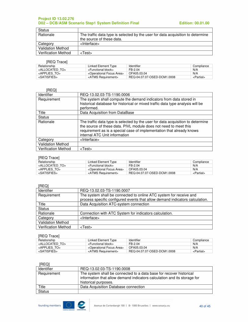
Project ID 13.02.276 D02 – DCB/ASM Scenario Step1 System Definition Final Edition: 00.01.00
40 of 45
Status
Rationale The traffic data type is selected by the user for data acquisition to determine the source of these data.
Category <Interface>
Validation Method
Verification Method <Test>
[REQ Trace]
Relationship Linked Element Type Identifier Compliance
<ALLOCATED_TO> <Functional block> FB-2.04 N/A <APPLIES_TO> <Operational Focus Area> OFA05.03.04 N/A
<SATISFIES> <ATMS Requirement> REQ-04.07.07-OSED-DCM1.0008 <Partial>
[REQ]
Identifier REQ-13.02.03-TS-1190.0006
Requirement The system shall compute the demand indicators from data stored in historical database for historical or mixed traffic data type analysis will be performed.
Title Data Acquisition from DataBase
Status
Rationale The traffic data type is selected by the user for data acquisition to determine the source of these data. PIVL module does not need to meet this requirement as is a special case of implementation that already knows internal ATC Unit information
Category <Interface>
Validation Method
Verification Method <Test>
[REQ Trace] Relationship Linked Element Type Identifier Compliance <ALLOCATED_TO> <Functional block> FB-2.04 N/A
<APPLIES_TO> <Operational Focus Area> OFA05.03.04 N/A
<SATISFIES> <ATMS Requirement> REQ-04.07.07-OSED-DCM1.0008 <Partial>
[REQ]
Identifier REQ-13.02.03-TS-1190.0007
Requirement The system shall be connected to online ATC system for receive and process specific configured events that allow demand indicators calculation.
Title Data Acquisition ATC-system connection
Status
Rationale Connection with ATC System for indicators calculation.
Category <Interface>
Validation Method
Verification Method <Test>
[REQ Trace] Relationship Linked Element Type Identifier Compliance
<ALLOCATED_TO> <Functional block> FB-2.04 N/A
<APPLIES_TO> <Operational Focus Area> OFA05.03.04 N/A
<SATISFIES> <ATMS Requirement> REQ-04.07.07-OSED-DCM1.0008 <Partial>
[REQ]
Identifier REQ-13.02.03-TS-1190.0008
Requirement The system shall be connected to a data base for recover historical information that allow demand indicators calculation and its storage for historical purposes.
Title Data Acquisition Database connection
Status
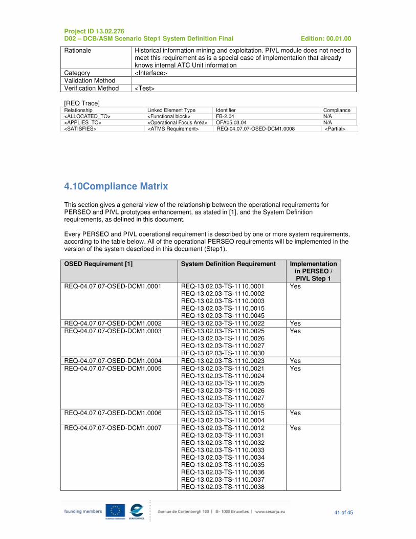
Project ID 13.02.276 D02 – DCB/ASM Scenario Step1 System Definition Final Edition: 00.01.00
41 of 45
Rationale Historical information mining and exploitation. PIVL module does not need to meet this requirement as is a special case of implementation that already knows internal ATC Unit information
Category <Interface>
Validation Method
Verification Method <Test>
[REQ Trace] Relationship Linked Element Type Identifier Compliance <ALLOCATED_TO> <Functional block> FB-2.04 N/A
<APPLIES_TO> <Operational Focus Area> OFA05.03.04 N/A
<SATISFIES> <ATMS Requirement> REQ-04.07.07-OSED-DCM1.0008 <Partial>
4.10Compliance Matrix This section gives a general view of the relationship between the operational requirements for PERSEO and PIVL prototypes enhancement, as stated in [1], and the System Definition requirements, as defined in this document. Every PERSEO and PIVL operational requirement is described by one or more system requirements, according to the table below. All of the operational PERSEO requirements will be implemented in the version of the system described in this document (Step1).
OSED Requirement [1] System Definition Requirement Implementation in PERSEO / PIVL Step 1
REQ-04.07.07-OSED-DCM1.0001 REQ-13.02.03-TS-1110.0001 REQ-13.02.03-TS-1110.0002 REQ-13.02.03-TS-1110.0003 REQ-13.02.03-TS-1110.0015 REQ-13.02.03-TS-1110.0045
Yes
REQ-04.07.07-OSED-DCM1.0002 REQ-13.02.03-TS-1110.0022 Yes
REQ-04.07.07-OSED-DCM1.0003 REQ-13.02.03-TS-1110.0025 REQ-13.02.03-TS-1110.0026 REQ-13.02.03-TS-1110.0027 REQ-13.02.03-TS-1110.0030
Yes
REQ-04.07.07-OSED-DCM1.0004 REQ-13.02.03-TS-1110.0023 Yes
REQ-04.07.07-OSED-DCM1.0005 REQ-13.02.03-TS-1110.0021 REQ-13.02.03-TS-1110.0024 REQ-13.02.03-TS-1110.0025 REQ-13.02.03-TS-1110.0026 REQ-13.02.03-TS-1110.0027 REQ-13.02.03-TS-1110.0055
Yes
REQ-04.07.07-OSED-DCM1.0006 REQ-13.02.03-TS-1110.0015 REQ-13.02.03-TS-1110.0004
Yes
REQ-04.07.07-OSED-DCM1.0007 REQ-13.02.03-TS-1110.0012 REQ-13.02.03-TS-1110.0031 REQ-13.02.03-TS-1110.0032 REQ-13.02.03-TS-1110.0033 REQ-13.02.03-TS-1110.0034 REQ-13.02.03-TS-1110.0035 REQ-13.02.03-TS-1110.0036 REQ-13.02.03-TS-1110.0037 REQ-13.02.03-TS-1110.0038
Yes
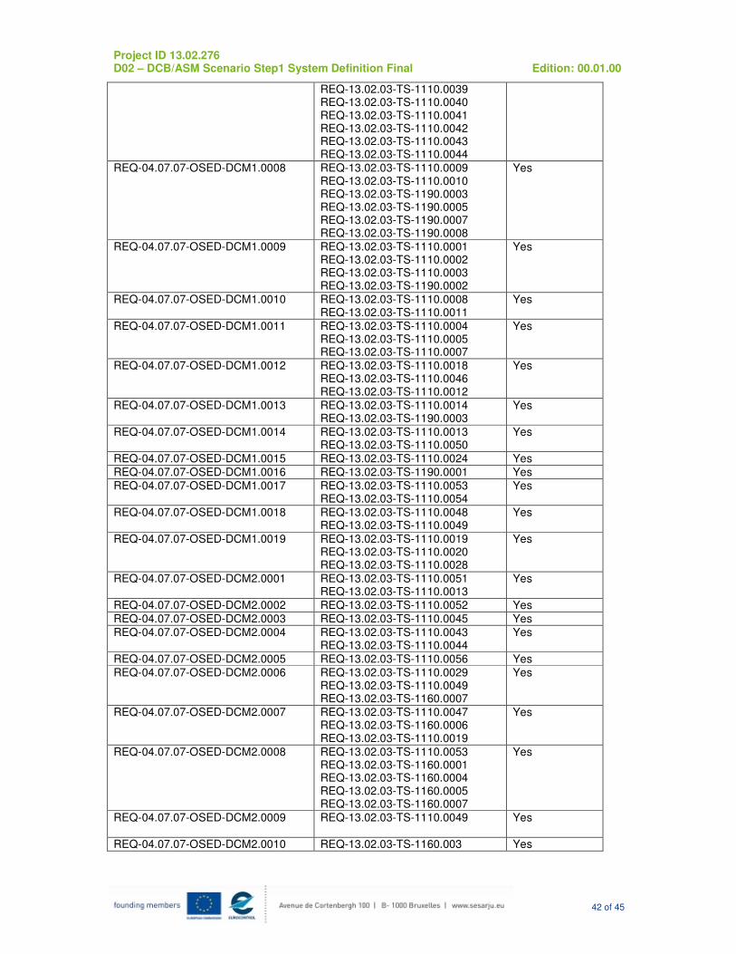
Project ID 13.02.276 D02 – DCB/ASM Scenario Step1 System Definition Final Edition: 00.01.00
42 of 45
REQ-13.02.03-TS-1110.0039 REQ-13.02.03-TS-1110.0040 REQ-13.02.03-TS-1110.0041 REQ-13.02.03-TS-1110.0042 REQ-13.02.03-TS-1110.0043 REQ-13.02.03-TS-1110.0044
REQ-04.07.07-OSED-DCM1.0008 REQ-13.02.03-TS-1110.0009 REQ-13.02.03-TS-1110.0010 REQ-13.02.03-TS-1190.0003 REQ-13.02.03-TS-1190.0005 REQ-13.02.03-TS-1190.0007 REQ-13.02.03-TS-1190.0008
Yes
REQ-04.07.07-OSED-DCM1.0009 REQ-13.02.03-TS-1110.0001 REQ-13.02.03-TS-1110.0002 REQ-13.02.03-TS-1110.0003 REQ-13.02.03-TS-1190.0002
Yes
REQ-04.07.07-OSED-DCM1.0010 REQ-13.02.03-TS-1110.0008 REQ-13.02.03-TS-1110.0011
Yes
REQ-04.07.07-OSED-DCM1.0011 REQ-13.02.03-TS-1110.0004 REQ-13.02.03-TS-1110.0005 REQ-13.02.03-TS-1110.0007
Yes
REQ-04.07.07-OSED-DCM1.0012 REQ-13.02.03-TS-1110.0018 REQ-13.02.03-TS-1110.0046 REQ-13.02.03-TS-1110.0012
Yes
REQ-04.07.07-OSED-DCM1.0013 REQ-13.02.03-TS-1110.0014 REQ-13.02.03-TS-1190.0003
Yes
REQ-04.07.07-OSED-DCM1.0014 REQ-13.02.03-TS-1110.0013 REQ-13.02.03-TS-1110.0050
Yes
REQ-04.07.07-OSED-DCM1.0015 REQ-13.02.03-TS-1110.0024 Yes
REQ-04.07.07-OSED-DCM1.0016 REQ-13.02.03-TS-1190.0001 Yes
REQ-04.07.07-OSED-DCM1.0017 REQ-13.02.03-TS-1110.0053 REQ-13.02.03-TS-1110.0054
Yes
REQ-04.07.07-OSED-DCM1.0018 REQ-13.02.03-TS-1110.0048 REQ-13.02.03-TS-1110.0049
Yes
REQ-04.07.07-OSED-DCM1.0019 REQ-13.02.03-TS-1110.0019 REQ-13.02.03-TS-1110.0020 REQ-13.02.03-TS-1110.0028
Yes
REQ-04.07.07-OSED-DCM2.0001 REQ-13.02.03-TS-1110.0051 REQ-13.02.03-TS-1110.0013
Yes
REQ-04.07.07-OSED-DCM2.0002 REQ-13.02.03-TS-1110.0052 Yes
REQ-04.07.07-OSED-DCM2.0003 REQ-13.02.03-TS-1110.0045 Yes
REQ-04.07.07-OSED-DCM2.0004 REQ-13.02.03-TS-1110.0043 REQ-13.02.03-TS-1110.0044
Yes
REQ-04.07.07-OSED-DCM2.0005 REQ-13.02.03-TS-1110.0056 Yes
REQ-04.07.07-OSED-DCM2.0006 REQ-13.02.03-TS-1110.0029 REQ-13.02.03-TS-1110.0049 REQ-13.02.03-TS-1160.0007
Yes
REQ-04.07.07-OSED-DCM2.0007 REQ-13.02.03-TS-1110.0047 REQ-13.02.03-TS-1160.0006 REQ-13.02.03-TS-1110.0019
Yes
REQ-04.07.07-OSED-DCM2.0008 REQ-13.02.03-TS-1110.0053 REQ-13.02.03-TS-1160.0001 REQ-13.02.03-TS-1160.0004 REQ-13.02.03-TS-1160.0005 REQ-13.02.03-TS-1160.0007
Yes
REQ-04.07.07-OSED-DCM2.0009 REQ-13.02.03-TS-1110.0049 Yes
REQ-04.07.07-OSED-DCM2.0010 REQ-13.02.03-TS-1160.003 Yes

Project ID 13.02.276 D02 – DCB/ASM Scenario Step1 System Definition Final Edition: 00.01.00
43 of 45
5References [1] SESAR 04.07.07.D25 Final OSED Edition 00.01.00 22/01/2013
[2] SESAR Template Toolbox 02.00.00
[3] SESAR Requirements and V&V Guidelines 02.00.00
[4] DEL_13.01.01.D04 NIMS Step 1 TAD Edition 00.00.01 12/10/2011

Project ID 13.02.276 D02 – DCB/ASM Scenario Step1 System Definition Final Edition: 00.01.00
44 of 45
Appendix A Traceability
Project ID 13.02.276 D02 – DCB/ASM Scenario Step1 System Definition Final Edition: 00.01.00
45 of 45
-END OF DOCUMENT -