Embed Size (px)
Citation preview

User Guide
DCM1500SDigital Clamp Meter
5 Commonwealth Ave Woburn, MA 01801 Phone 781-665-1400 Toll Free 1-800-517-8431
Visit us at www.TestEquipmentDepot.com

DCM1500S User Guide2

Declaration of ConformityHereby, Megger Instruments Limited declares that radio equipment manufactured by Megger Instruments Limited described in this user guide is in compliance with Directive 2014/53/EU. Other equipment manufactured by Megger Instruments Limited described in this user guide is in compliance with Directives 2014/30/EU and 2014/35/EU where they apply.
The full text of Megger Instruments EU declarations of conformity are available at the following internet address
megger.com/company/about-us/eu-dofc
This manual supersedes all previous issues of this manual. Please ensure that you are using the most recent issue of this document. Destroy any copies that are of an older issue.
DCM1500S User Guide 3

G Safety Information
Understand and follow the operating instructions carefully.
G WARNING
Identify hazardous conditions and actions that could cause BODILY HARM or DEATH
� When using test leads or probes, keep your fingers behind the finger guards.
� Personal protective equipment should be used if there are ACCESSIBLEHAZARDOUS LIVE PARTS in the installation where measurement is to be carriedout.
� Remove test leads from meter before opening the battery door or meter case.
� Use the meter only as specified in this manual; otherwise, the protection providedby the meter may be impaired.
� Always use the proper input terminals, switch position, and range formeasurements.
� Verify the meters operation by measuring a known voltage. If in doubt, have themeter calibrated.
� Do not apply more than the rated voltage, as marked on the meter, betweenterminals or between any terminal and earth.
� Use caution with voltages above 30 V AC rms, 42 V AC peak, or 60 V DC. Thesevoltages pose a shock hazard.
� To avoid false readings that can lead to electric shock and injury, replace thebattery as soon as the low battery indicator blinks.
� Disconnect circuit power and discharge all high-voltage capacitors before testingresistance, continuity, diodes, or capacitance.
� Do not use the meter around explosive gas or vapour.
� To reduce the risk of fire or electric shock do not expose this product to rain ormoisture.
� Probe assemblies to be used for MAINS measurements shall be RATED asappropriate for MEASUREMENT CATEGORY III or IV according to EN 61010-031 and shall have a voltage RATING of at least the voltage of the circuit to bemeasured.
DCM1500S User Guide4

G Safety Information
■ DO NOT USE the test leads if the internal white insulation layer is exposed.■ DO NOT USE the test leads above maximum ratings of CAT Environment or
voltage and current that are indicated on the probe and probe tip guard.■ Do not apply a current with a frequency that is higher than the frequency
response range specified in the Electrical Specifications section.■ Do not apply or remove the clamp or test leads on or around uninsulated
hazardous live conductors where a potential to cause electric shock, electricalburns or arc flash exists.
G CAUTION
� Disconnect the test leads from the test points before changing the position of thefunction rotary switch.
� Never connect a source of voltage with the function rotary switch in Ω, and position.
� Do not expose the meter to extremes of temperature or high humidity.
DCM1500S User Guide 5

Symbols as marked on the Meter and Instruction manual
Risk of electric shock
See instruction manual
DC measurement
AC measurement
Both direct and alternating current
Equipment protected by double or reinforced insulation
Battery
Earth
Conforms to EU directives
Conforms to UKCA directives
Application around and removal from hazardous live conductors
Do not discard this product or throw away
Bluetooth®
CATIV
Measurement category IV: Equipment connected between the origin of the low-voltage mains supply outside the building and the consumer unit.
CATIII
Measurement category III: Equipment connected between the consumer unit and the electrical outlets.
CATII
Measurement category II: Equipment connected between the electrical outlets and the user’s equipment.
G Unsafe Voltage
� To alert you to the presence of a potentially hazardous voltage, when the tester
detects a voltage ≥30 V or a voltage overload (OL) in V, mV, PV. The V symbol isdisplayed.
DCM1500S User Guide6

Features
� 6000 Count LCD display
� Backlight
� VoltSeek (Non-Contact Voltage Detection)
� True RMS reading on AC
� Data logger (up to 4000 sample values)
� Manual save mode
� Bluetooth® communication
� Torch turns on when clamp jaws open
� 1500 A AC/DC current measurement
� DC voltage measurement up to 2000 V using the PVHV lead set
� AV voltage measurement up to 1500 V using the PVHV lead set
� 600 kΩ Resistance measurement / continuity beeper
� Frequency counter
� Capacitance/Diode test
� °C/°F Temperature function
� Inrush current
� DCA auto-zeroing button
� Max/Min hold
� Smart hold
� High frequency noise rejection filter
� Auto power off (APO)
� CAT IV 600 V/CAT III 1000 V safety standard
DCM1500S User Guide 7

Unpacking and Inspection
Upon removing your new Solar/PV Clamp Meter from its packing, you should have the following items:
� Megger DCM1500S Solar/PV Clamp Meter
� Test lead set (one black, one red)
� Test probes (one black, one red)
� Crocodile clips (one black, one red)
� TP100 Temperature probe
� Megger PVHV1 Lead set (4mm plugs)
� Megger PVHV2 Lead set (MC4 PV plugs)
� User Manual
� Carry case
� Batteries
DCM1500S User Guide8

The Meter Description
1 JAW
2 VoltSeek LED
3 Push button
4 Trigger
5 Rotary switch to turn the instrument On / Off and select a function
6 6,000 count LCD display
7 Positive input terminal
8 Common (earth reference) input terminal
Function Button
DCM1500S User Guide 9

Making Basic Measurements
Preparation and Caution Before Measurement
G Observe the rules of G Warnings and G Cautions.
G CAUTION
When connecting the test leads to the DUT (Device Under Test) connect the common test lead before connecting the live test lead. When removing the test leads remove the live test lead before removing the common test lead.
Measuring Voltage
Turn the switch to select the measuring function.
DCM1500S User Guide10

Measuring PV Voltage
Turn the switch and press the Function button to select AC/DC mode
G CAUTION
This function is only available with the dedicated PVHV test lead sets.
The PVHV test leads are designed for use in environments that are not directly connected to the mains. Always select correct AC/DC mode to perform any high voltage measurement.
The meter will flash this symbol F and the correct mode symbol (AC/DC) if the inputvoltage is different and/or dangerous.
PV String
DCM1500S User Guide 11

Measuring Current
Turn the switch and press the Function button to select AC/DC/Hz mode.
Note: The torch will turn on when the jaw is opened.
GCAT IV 600 V
CAT III 1000 V
Fixed barrier hand guard
G Do not hold the meteracross the fixed barrier
DCM1500S User Guide12
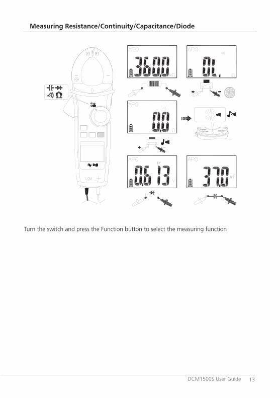
Measuring Resistance/Continuity/Capacitance/Diode
Turn the switch and press the Function button to select the measuring function
DCM1500S User Guide 13

Measuring Temperature °C / °F
Turn the switch and press the Function button to select °C / °F mode.
Function button
K Type Temperature
Probe
Vent / Pipe
DCM1500S User Guide14

Measuring µA
Turn the switch and press the Function button to select AC/DC mode.
(Example)
Flame sensor
Control module
DCM1500S User Guide 15

Using the Function Button
Switch Position
Function
Press the Function button to change the function for each rotary switch position.
DCM1500S User Guide16

Measuring Frequency
Function button
Backlight
Press > 2 sec
2 sec
Press Function button for over 2 seconds to turn Backlight on or off.
DCM1500S User Guide 17

MIN/MAX
>2 sec to exitthe MIN/MAXmode
Press
The MIN/MAX mode records the min and max input values.
When the input goes below the recorded min value or above the recorded max value, the meter beeps and records the new value. Press Hold button to pause the recording.
DCM1500S User Guide18

Volt Seek
Sensor position
Volt Seek 2 sec
Do not hold across this line when sensing the hazardous voltage
Press MIN/MAX button for over 2 seconds to enter/exit Volt Seek mode. Press MIN/MAX button to switch from high to low sensitivity.
G WARNING
The Volt Seek LED indicates the electric field. If the Volt Seek LED is not on, voltage could still be present.
DCM1500S User Guide 19
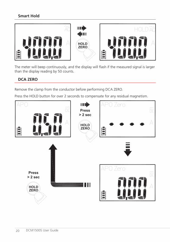
Smart Hold
The meter will beep continuously, and the display will flash if the measured signal is larger than the display reading by 50 counts.
DCA ZERO
Remove the clamp from the conductor before performing DCA ZERO.
Press the HOLD button for over 2 seconds to compensate for any residual magnetism.
Press > 2 sec
Press > 2 sec
DCM1500S User Guide20

High Frequency Rejection Filter (HFR)
The High Frequency Rejection (HFR) mode uses a low pass filter when taking AC measurements. The cut-off frequency (-3 dB point) of the low pass filter is 800 Hz.
Press
F WARNING
Hazardous voltages may still be present when the LCD reading is very low in HFR mode. Verify the voltage again without HFR mode activated.
DCM1500S User Guide 21

INRUSH
When using the inrush current mode, select a suitable measurement range before pressing the HFR/INRUSH button and triggering the inrush current measurement feature.
Motor Off
Trigger Point
Press > 2 sec
Press > 2 sec
Inrush 2 sec
Inrush 2 sec
The current is > trigger level
Motor On Time
Detecting
DCM1500S User Guide22

Auto Power Off
After user specified time with no operation (Note Time Setting of Auto Power Off)
Wake up the meter by turning the switch or pressing any button.
Time Setting of Auto Power Off
Function Button
Function Button
Press and hold the function button whilst turning the meter on, the meter beeps 3 times prior to APO (Auto Power Off) activating.
Release the function button and press it again to select the desired time. The auto power off time can be set to 5 mins,10 mins, 20 mins, or disabled (OFF).
DCM1500S User Guide 23

Testing LCD Display
Turn on the meter while keeping HOLD button pressed.
DCM1500S User Guide24

Function of LOG Button
Press
Press the Bluetooth® button while powering-up to select the Logger mode, Manual Saving mode or Clear the memory.
DCM1500S User Guide 25

Data Logger
The meter can store up to 4000 data entries in internal memory.
Press the Bluetooth® button for more than 2 seconds to activate data logger mode. The meter will enter time interval setting mode. Press the Bluetooth® button again to select the desired sample interval. This can be set to 1, 5, 10, 30 or 60 seconds.
Press > 2 sec
Time interval setting mode
PressPress
Press
Start to record automatically after 2 seconds without operation
LOG icon flashes while logging
G CAUTION
All stored data is cleared at the start of each data log or when Clr (Clear) or Save (Manual Saving) is selected. Data can be downloaded and saved for analysis by the Megger Link App.
DCM1500S User Guide26

Manual Saving Mode
Press > 2 sec
Flash
To save a reading
Show stored reading amount for 2 seconds
If Manual Saving is selected, readings can be stored by pressing the Hold/Zero button when in Log mode. The sample location is displayed on each button press.
G CAUTION
All stored data is saved until switching to data logger mode or executing the clear function.
DCM1500S User Guide 27

Bluetooth®
The meter uses Bluetooth® low energy (BLE) V4.0 wireless technology to transfer the real-time reading and the stored data. The open-air communication range is up to 10 meters.
Download the “Megger Link” App. Turn on the Bluetooth function of the meter by pressing the Bluetooth button and open the Megger Link App to connect the DCM. The Bluetooth icon of the meter will flash whilst connecting and remain on the LCD once the connection is established.
QR Code for the Megger Link App on the Google Play Store
QR Code for the Megger Link App on the Apple App Store
DCM1500S User Guide28

Default Temperature Units Setting
OR
Press and hold the MIN/MAX button whilst turning the meter on to select °C or °F.
DCM1500S User Guide 29

Low Battery and Battery Replacement
Replace the battery as soon as the low battery indicator appears to avoid false readings. Refer to the following figure to replace the batteries
G CAUTION
Remove test leads from meter before opening the battery cover or meter case.
DCM1500S User Guide30

Specifications
General Specifications
Display count : 6,000 counts.
Overrange display : « OL » or « -OL »
Measurement frequency : 3 times per second
Maximum Conductor Size of JAW:
42 mm diameter
Dimensions (W x H x D) : 62 x 254 x 41 mm
Weight (approx.) : 480 g (including battery)
Low Batteries Indication If battery voltage drops below the operating voltage, will flash.
Power requirements : AA size battery x 2 (R6, LR6, 15D, 15A)
Battery life : Approximately 200 hours (based on Alkaline batteries without using the backlight).
Environmental Conditions
Indoor Use Only
Pollution degree : 2
Maximum Operating Altitude : 2,000 m (6562 ft)
Operating Temperature & Relative Humidity :
-10 °C ~ 10 °C,-10 °C ~ 30 °C, ≤80 % RH.30 °C ~ 40 °C, ≤75 % RH.40 °C ~ 50 °C, ≤45 % RH.
Storage temperature : -20 to +60 °C, 0 to 80 % RH.(batteries not fitted)
Vibration : Random Vibration per MIL-PRF-28800F Class 2
Drop Protection : 1.2 m (4 ft) drop to hardwood on concrete floor
Safety : EN 61010-1, EN 61010-2-032, EN 61010-2-033 for CAT III 1000 V, CAT IV 600 V, EN 61326-1
DCM1500S User Guide 31

Electrical SpecificationsAccuracy is given as ± (% of reading + counts of least significant digit) at 23°C ± 5°C, with relative humidity less than 80% and is specified for 1 year after calibration.
Temperature coefficient : 0.1 x (Specified accuracy) / °C, < 18 °C, > 28 °C
AC Function : � ACV and ACA specifications are AC coupled,true RMS.
� Accuracy is unspecified for a Square Wave.
� For non-sinusoidal waveforms, AdditionalAccuracy by Crest Factor (C.F.):Add 3.0% for C.F. 1.0 ~ 2.0Add 5.0% for C.F. 2.0 ~ 2.5Add 7.0% for C.F. 2.5 ~ 3.0
� Max. Crest Factor of Input Signal:3.0 @ 3000 counts2.0 @ 4500 counts1.5 @ 6000 counts
� Frequency Response is specified for sinewaveform. LCD displays 0 counts when thereading < 20 counts.
DC mV
Range OL Reading Resolution Accuracy
600.0 mV 660.0 mV 0.1 mV ± (0.7% + 5D)
Input Impedance : 10 MΩ
Overload Protection : AC/DC 1,000 V
DC Voltage
Range OL Reading Resolution Accuracy
600.0 V 660.0 V 0.1 V± (0.7% + 2D)
1000 V 1100 V 1 V
Input Impedance : 10 MΩ
Overload Protection : AC/DC 1,000 V
DCM1500S User Guide32

AC Voltage
Range OL Reading Resolution Accuracy
600.0 V 660.0 V 0.1 V± (1.0% + 5D)
1000 V 1100 V 1 V
Input Impedance : 10MΩ // less than 100pF
Frequency Response : 45 ~ 400Hz (Sine Wave)
Overload Protection : AC/DC 1,000 V
PV DC Voltage (using PVHV1 or PVHV2 lead set)
Range OL Reading Resolution Accuracy
600.0 V 660.0 V 0.1 V± (2.0% + 5D)
2000 V 2200 V 1 V
Input Impedance : 10MΩ
Overload Protection : AC/DC 1,000 V
PV AC Voltage (using PVHV1 or PVHV2 lead set)
Range OL Reading Resolution Accuracy
600.0 V 660.0 V 0.1 V± (2.0% + 5D)
1500 V 1600 V 1 V
Input Impedance : 10MΩ
Frequency Response : 45 ~ 400Hz (Sine Wave)
Overload Protection : AC/DC 1,000 V
AC/DC µA
Range OL Reading Resolution Accuracy
400.0 µA 440.0 µA 0.1 µA± (1.0% + 3D)
4000 µA 4400 µA 1 µA
Input Impedance : Approx. 2.2 kΩ
Frequency Response : 45 ~ 400Hz (Sine Wave)
Overload Protection : AC/DC 1,000 V
DCM1500S User Guide 33

AC/DC Current
Range OL Reading Resolution Accuracy
60.00 A 66.00 A 0.01 A
± (2.0% + 5D)600.0 A 660.0 A 0.1 A
1500 A 1550 A 1 A
Add 10 digits to the accuracy when <5.0 A. Add 0.5% to the accuracy when >1000 A. Add 1% to the accuracy when >100 Hz.
Frequency Response : (Sine Wave) 45 ~ 400 Hz for ≤1000 A
45 ~ 65 Hz for >1000 A
Overload Protection : AC/DC 1500 A
Frequency
Range OL Reading Resolution Accuracy
100.00 Hz 100.00 Hz 0.01 Hz
± (0.3% + 3D)1000.0 Hz 1000.0 Hz 0.1 Hz
10.000 kHz 10.000 kHz 0.001 kHz
Minimum Sensitivity : > 5 V (for ACV 1 Hz ~ 10 kHz)
> 8 A (for ACA 1 Hz ~ 1 kHz)
Minimum Frequency : 1 Hz
Overload Protection : AC/DC 1000 V and 1500 A
HFR (High Frequency Rejection)
Available for ACV and ACA. Add ± 4% to specified accuracy of each function and each range for 45 Hz to 200 Hz. Accuracy is unspecified for > 200 Hz.
Cut-off Frequency (-3 dB): 800 Hz
Inrush Current
Available for ACA and Flexible Current Probe. Trigger level: ≥50d.
Add ± 3% to specified accuracy of each function and each range.
DCM1500S User Guide34

Resistance
Range OL Reading Resolution Accuracy
600.0 Ω 660.0 Ω 0.1 Ω ± (0.9% + 5D)
6.000 kΩ 6.600 kΩ 0.001 kΩ
± (0.9% + 2D)60.00 kΩ 66.00 kΩ 0.01 kΩ
600.0 kΩ 660.0 kΩ 0.1 kΩ
To obtain a more accurate reading, the lead resistance should be measured by connecting the probes/clips together and the result deducted from any resistance measurement taken.
Overload Protection : AC/DC 1000 V
Continuity
Built-in buzzer sounds when measured resistance is less than 20Ω and the sound is off when measured resistance is more than 200 Ω, between 20 Ω to 200 Ω the buzzer may be either on or off.
Continuity Indicator : 2.7 kHz Tone Buzzer
Response Time of Buzzer : < 100 ms
Overload Protection : AC/DC 1000 V
Diode
Range OL Reading Resolution Accuracy
1.500 V 1.550 V 0.001 V ± (0.9% + 2D)
Open Circuit Voltage : Approx. 1.8 V
Overload Protection : AC/DC 1000 V
Capacitance
Range OL Reading Resolution Accuracy
100.0 µF 110.0 µF 0.1 µF± (1.9% + 2D)
1000 µF 1100 µF 1 µF
Overload Protection : AC/DC 1000 V
DCM1500S User Guide 35

VoltSeek
Voltage Range of High Sensitivity :
80 V ~ 1000 V (At the top edge of the jaw)
Voltage Range of Low Sensitivity :
160 V ~ 1000 V (At the top edge of the jaw)
Temperature
Range OL Reading Resolution Accuracy
-40.0 °C – 400.0 °C 440.0 °C 0.1 °C ± (1% + 20D)
-40.0 °F – 752.0 °F 824.0 °F 0.1 °F ± (1% + 36D)
The accuracy does not include the accuracy of the thermocouple probe. Accuracy specification assumes surrounding temperature stable to ±1 °C. For surrounding temperature changes of ± 2 °C rated accuracy applies after 2 hours.
Overload Protection : AC/DC 1000 V
Specification PVHV1 (4mm plugs) and PVHV2 (MC4) test leads
Input Impedance : 10 MΩ
Overvoltage Category : CAT II 1000 V AC ,1500 V DC CAT III 1000 V, CAT IV 600 V.
Pollution Degree : 2
Exposed probe tip length : Test probe: 18 mm to 3.5 mm (0.70 inch to 0.14 inch)
Environmental ratings : -10 °C to 45 °C (-4 °F to 113 °F), 80% R.H.
Altitude : 2000 m (6,562 ft)
Safety Standard : EN61010-031
Product manufactured in Taiwan
DCM1500S User Guide36

Maintenance
Do not attempt to repair this meter. It contains no user-serviceable parts. Repair or servicing should only be performed by qualified personnel.
Cleaning
Periodically wipe the case with a dry cloth and detergent, do not use abrasives or solvents
WEEE Directive
The crossed out wheeled bin symbol on the instrument and on the batteries is a reminder not to dispose of them with general waste at the end of their life. Megger is registered in the UK as a Producer of Electrical and Electronic equipment. The registration No is; WEE/DJ2235XR.
Users of Megger products in the UK may dispose of them at the end of their useful life by contacting B2B Compliance at www.b2bcompliance.org.uk or by telephone on 01691676124.
Users of Megger products in other regions should contact their local Megger office or distributor.
Battery Disposal
The batteries in this product are classified as Portable Batteries under the Batteries Directive. Please contact either Megger Ltd, your local Megger office or distributor for instructions on the safe disposal of these batteries. Megger is registered in the UK as a producer of batteries. The registration number is BPRN01235.
DCM1500S User Guide 37

Warranty (3 years)
This meter is warranted to the original purchaser against defects in material and workmanship for 3 year from the date of purchase.
During this warranty period, the manufacturer will, at its option, replace or repair the defective unit, subject to verification of the defect or malfunction.
This warranty does not cover fuses, disposable batteries, or damage from abuse, neglect, accident, unauthorised repair, alteration, contamination, or abnormal conditions of operation or handling.
Any implied warranties arising out of the sale of this product, including but not limited to implied warranties of merchantability and fitness for a particular purpose, are limited to the above. The manufacturer shall not be liable for loss of use of the instrument or other incidental or consequential damages, expenses, or economic loss, or for any claim or claims for such damage, expense or economic loss. Some states or countries laws vary, so the above limitations or exclusions may not apply to you.
Megger Limited Archcliffe Road Dover Kent CT17 9EN
DCM1500S User Guide38

This instrument is manufactured in Taiwan.
The company reserves the right to change the specification or design without prior notice.
Megger is a registered trademark
The Bluetooth® word mark and logos are registered trademarks owned by Bluetooth SIG, Inc and is used under licence.
Part No: DCM1500S_1013-357_UG_EN_V02
© Megger Limited 2020
5 Commonwealth Ave Woburn, MA 01801 Phone 781-665-1400 Toll Free 1-800-517-8431
Visit us at www.TestEquipmentDepot.com