Embed Size (px)
Citation preview
DCP 550 Digital Control Programmer Specifications 57-77-03-12 February 1995
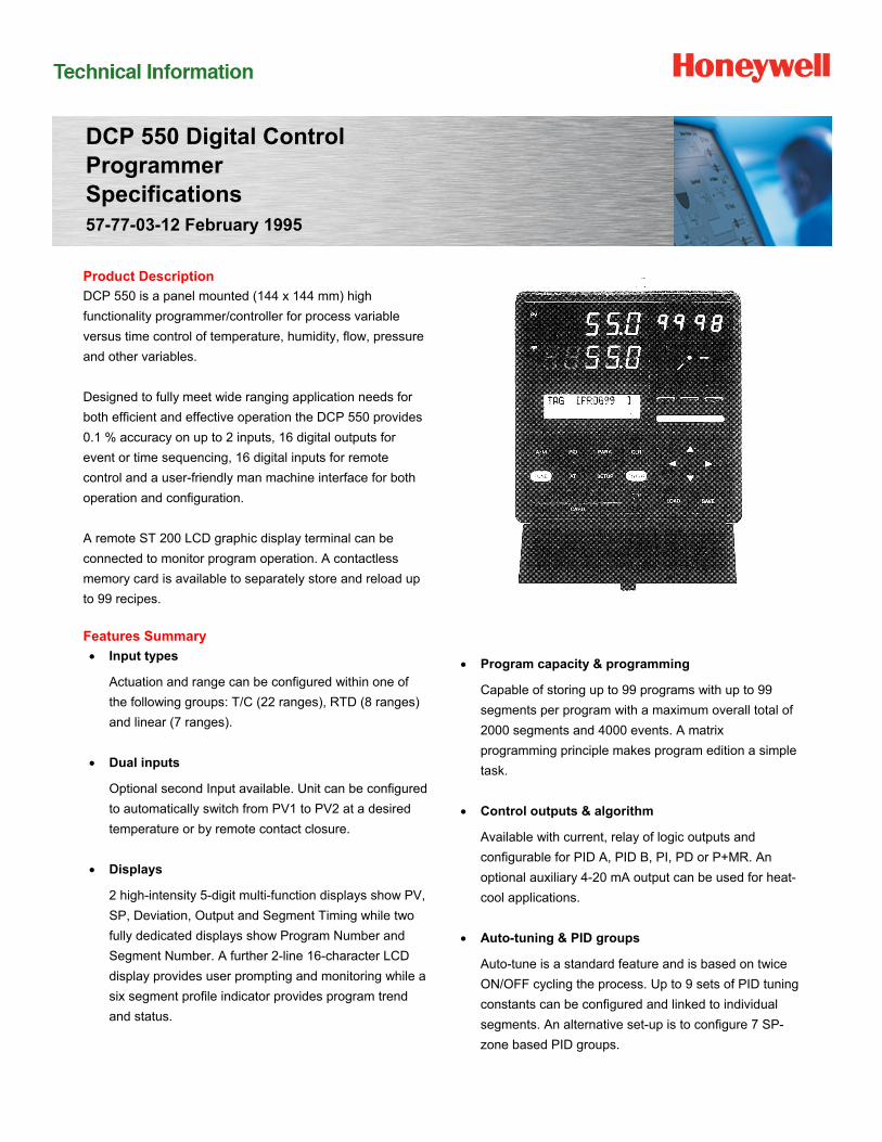
Product Description
DCP 550 is a panel mounted (144 x 144 mm) high
functionality programmer/controller for process variable
versus time control of temperature, humidity, flow, pressure
and other variables.
Designed to fully meet wide ranging application needs for
both efficient and effective operation the DCP 550 provides
0.1 % accuracy on up to 2 inputs, 16 digital outputs for
event or time sequencing, 16 digital inputs for remote
control and a user-friendly man machine interface for both
operation and configuration.
A remote ST 200 LCD graphic display terminal can be
connected to monitor program operation. A contactless
memory card is available to separately store and reload up
to 99 recipes.
Features Summary
Input types
Actuation and range can be configured within one of
the following groups: T/C (22 ranges), RTD (8 ranges)
and linear (7 ranges).
Dual inputs
Optional second Input available. Unit can be configured
to automatically switch from PV1 to PV2 at a desired
temperature or by remote contact closure.
Displays
2 high-intensity 5-digit multi-function displays show PV,
SP, Deviation, Output and Segment Timing while two
fully dedicated displays show Program Number and
Segment Number. A further 2-line 16-character LCD
display provides user prompting and monitoring while a
six segment profile indicator provides program trend
and status.
Program capacity & programming
Capable of storing up to 99 programs with up to 99
segments per program with a maximum overall total of
2000 segments and 4000 events. A matrix
programming principle makes program edition a simple
task.
Control outputs & algorithm
Available with current, relay of logic outputs and
configurable for PID A, PID B, PI, PD or P+MR. An
optional auxiliary 4-20 mA output can be used for heat-
cool applications.
Auto-tuning & PID groups
Auto-tune is a standard feature and is based on twice
ON/OFF cycling the process. Up to 9 sets of PID tuning
constants can be configured and linked to individual
segments. An alternative set-up is to configure 7 SP-
zone based PID groups.
HFS Catalog_Without Tab_HighRes.pdf 346 6/8/2011 12:41:18 PM
DCP 550 Digital Control Programmer 2
Digital inputs
16 dry contact inputs permit remote selection of
Program Number, Run, Hold, Reset, Segment
Advance, Fast Forward, Guaranteed Soak Reset, Auto-
tune Initiation, Manual Control, PV channel selection.
Digital outputs
16 fully configurable open-collector digital outputs can
be triggered by PV, SP, Deviation, Output, Program
Status, Auto-tune Operation and Diagnostic Checks.
An Event Code feature in addition can transmit
Program and Segment Number to an external PLC.
Memory card
A optional memory card permits saving, retrieval and
loading of up to 99 recipes and includes not only
program but also associated event settings.
Contactless technology guarantees troublefree
operation in harsh environments. Available in 8, 16 and
64K capacity. Full instrument configuration can also be
saved on the memory card, but only one full
configuration per card.
Remote graphic display
An optional LCD terminal connected via an RS485
communication link provides remote indication (up to
300 meters) of Program Number, Segment Number,
Elapsed Time and both SP and PV time profiles.
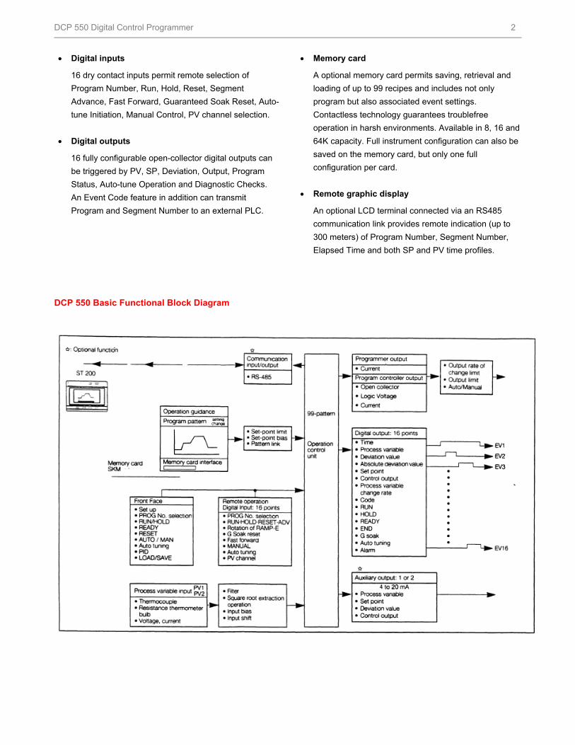
DCP 550 Basic Functional Block Diagram
HFS Catalog_Without Tab_HighRes.pdf 347 6/8/2011 12:41:18 PM
DCP 550 Digital Control Programmer 3
Specifications
Program Pattern
Storage capacity
No. of segments + No. of subfunctions
No of Patterns
99 patterns
No of Segments
99 segments per pattern
Total Number of segments
2000 segments
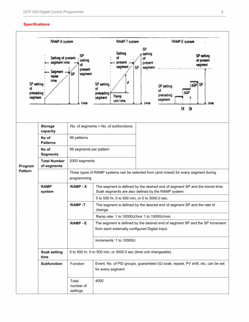
Three types of RAMP systems can be selected from (and mixed) for every segment during
programming
RAMP system
RAMP - X The segment is defined by the desired end of segment SP and the transit time. Soak segments are also defined by the RAMP system.
0 to 500 hr, 0 to 500 min, or 0 to 3000.0 sec.
RAMP -T The segment is defined by the desired end of segment SP and the rate of change.
Ramp rate: 1 to 10000U/hror 1 to 10000U/min
RAMP - E The segment is defined by the desired end of segment SP and the SP increment
from each externally configured Digital Input.
Increments: 1 to 10000U
Soak setting time
0 to 500 hr, 0 to 500 min, or 3000.0 sec (time unit changeable).
Subfunction Function Event, No. of PID groups, guaranteed (G) soak, repeat, PV shift, etc. can be set
for every segment
Total number of settings
4000
HFS Catalog_Without Tab_HighRes.pdf 348 6/8/2011 12:41:18 PM
DCP 550 Digital Control Programmer 4
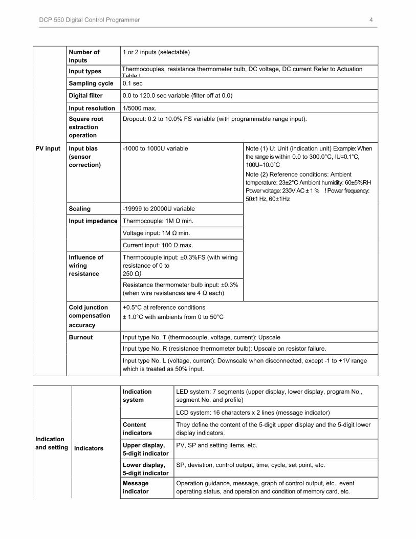
Number of
Inputs 1 or 2 inputs (selectable)
Input types Thermocouples, resistance thermometer bulb, DC voltage, DC current Refer to Actuation Table |
Sampling cycle 0.1 sec
Digital filter 0.0 to 120.0 sec variable (filter off at 0.0)
Input resolution 1/5000 max.
Square root extraction operation
Dropout: 0.2 to 10.0% FS variable (with programmable range input).
PV input
Input bias (sensor correction)
-1000 to 1000U variable Note (1) U: Unit (indication unit) Example: When the range is within 0.0 to 300.0°C, IU=0.1°C, 100U=10.0°C
Note (2) Reference conditions: Ambient temperature: 23±2°C Ambient humidity: 60±5%RH Power voltage: 230V AC ± 1 % ! Power frequency: 50±1 Hz, 60±1Hz
Scaling -19999 to 20000U variable
Input impedance Thermocouple: 1M Ω min.
Voltage input: 1M Ω min.
Current input: 100 Ω max.
Influence of wiring resistance
Thermocouple input: ±0.3%FS (with wiring resistance of 0 to 250 Ω)
Resistance thermometer bulb input: ±0.3% (when wire resistances are 4 Ω each)
Cold junction compensation
accuracy
+0.5°C at reference conditions
± 1.0°C with ambients from 0 to 50°C
Burnout Input type No. T (thermocouple, voltage, current): Upscale
Input type No. R (resistance thermometer bulb): Upscale on resistor failure.
Input type No. L (voltage, current): Downscale when disconnected, except -1 to +1V range which is treated as 50% input.
Indication and setting
Indicators
Indication system
LED system: 7 segments (upper display, lower display, program No., segment No. and profile)
LCD system: 16 characters x 2 lines (message indicator)
Content indicators
They define the content of the 5-digit upper display and the 5-digit lower display indicators.
Upper display, 5-digit indicator
PV, SP and setting items, etc.
Lower display, 5-digit indicator
SP, deviation, control output, time, cycle, set point, etc.
Message indicator
Operation guidance, message, graph of control output, etc., event operating status, and operation and condition of memory card, etc.
HFS Catalog_Without Tab_HighRes.pdf 349 6/8/2011 12:41:18 PM
DCP 550 Digital Control Programmer 5
Indication and setting
Indicators
(continued)
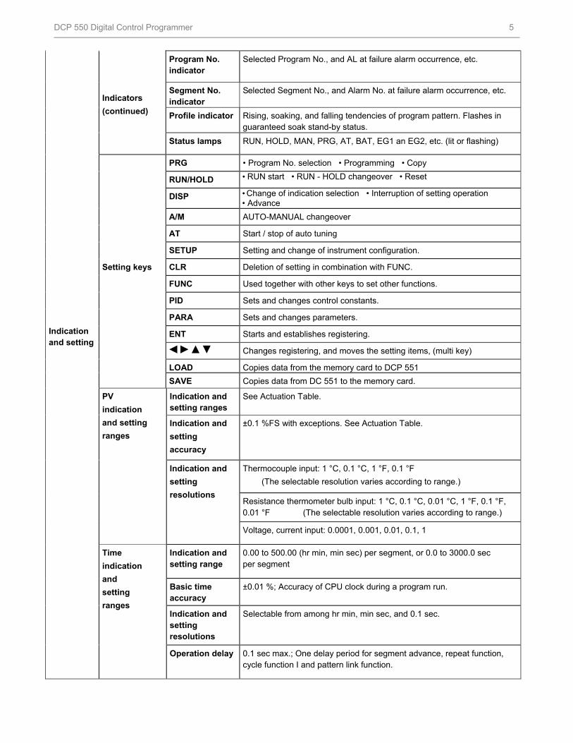
Program No. indicator
Selected Program No., and AL at failure alarm occurrence, etc.
Segment No. indicator
Selected Segment No., and Alarm No. at failure alarm occurrence, etc.
Profile indicator Rising, soaking, and falling tendencies of program pattern. Flashes in guaranteed soak stand-by status.
Status lamps RUN, HOLD, MAN, PRG, AT, BAT, EG1 an EG2, etc. (lit or flashing)
PRG • Program No. selection • Programming • Copy
RUN/HOLD • RUN start • RUN - HOLD changeover • Reset
DISP • Change of indication selection • Interruption of setting operation • Advance
A/M AUTO-MANUAL changeover
AT Start / stop of auto tuning
SETUP Setting and change of instrument configuration.
Setting keys CLR Deletion of setting in combination with FUNC.
FUNC Used together with other keys to set other functions.
PID Sets and changes control constants.
PARA Sets and changes parameters.
ENT Starts and establishes registering.
Changes registering, and moves the setting items, (multi key)
LOAD Copies data from the memory card to DCP 551
SAVE Copies data from DC 551 to the memory card.
PV
indication
and setting
ranges
Indication and setting ranges
See Actuation Table.
Indication and
setting
accuracy
±0.1 %FS with exceptions. See Actuation Table.
Indication and
setting
resolutions
Thermocouple input: 1 °C, 0.1 °C, 1 °F, 0.1 °F
(The selectable resolution varies according to range.)
Resistance thermometer bulb input: 1 °C, 0.1 °C, 0.01 °C, 1 °F, 0.1 °F, 0.01 °F (The selectable resolution varies according to range.)
Voltage, current input: 0.0001, 0.001, 0.01, 0.1, 1
Time
indication
and
setting
ranges
Indication and setting range
0.00 to 500.00 (hr min, min sec) per segment, or 0.0 to 3000.0 sec per segment
Basic time accuracy
±0.01 %; Accuracy of CPU clock during a program run.
Indication and setting resolutions
Selectable from among hr min, min sec, and 0.1 sec.
Operation delay 0.1 sec max.; One delay period for segment advance, repeat function, cycle function I and pattern link function.
HFS Catalog_Without Tab_HighRes.pdf 350 6/8/2011 12:41:19 PM
DCP 550 Digital Control Programmer 6
Control
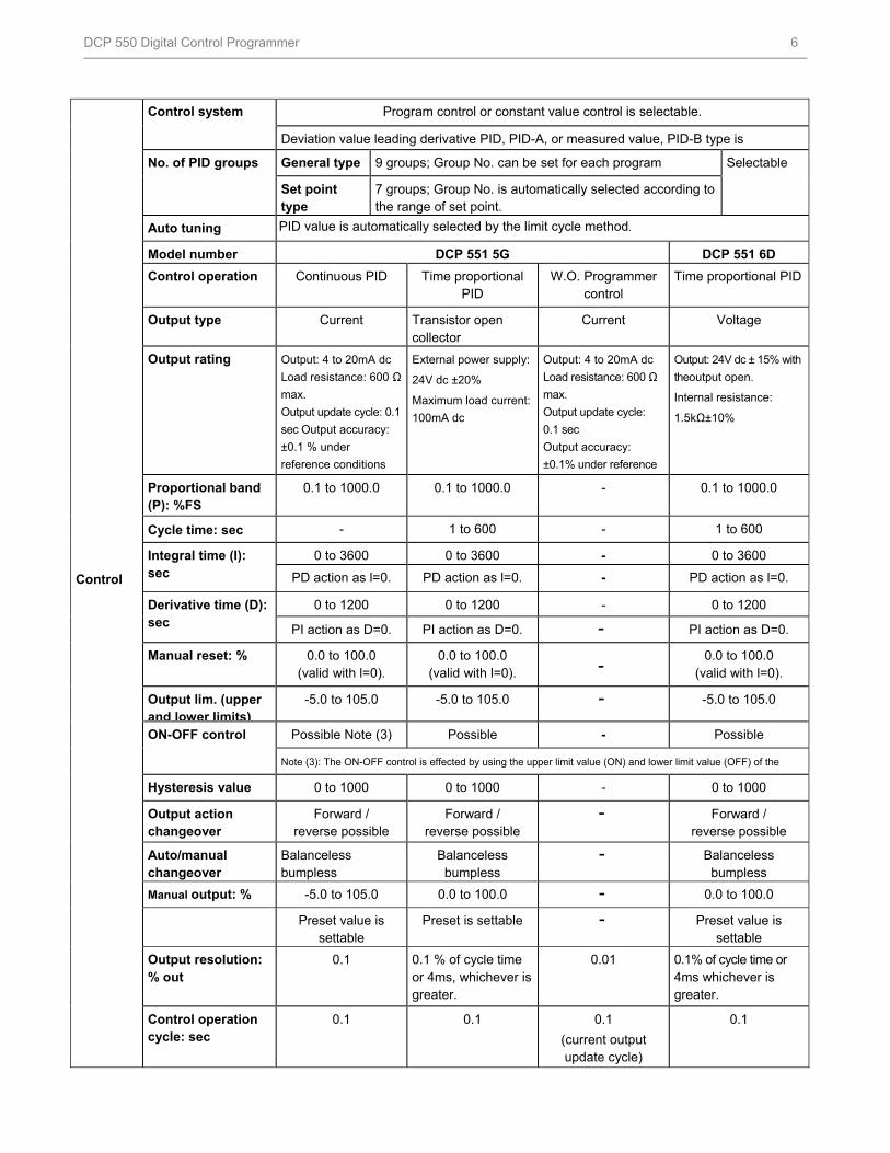
Control system Program control or constant value control is selectable.
Deviation value leading derivative PID, PID-A, or measured value, PID-B type is
No. of PID groups General type 9 groups; Group No. can be set for each program t
Selectable
Set point type
7 groups; Group No. is automatically selected according to the range of set point.
Auto tuning PID value is automatically selected by the limit cycle method.
Model number DCP 551 5G DCP 551 6D
Control operation Continuous PID Time proportional PID
W.O. Programmer control
Time proportional PID
Output type Current Transistor open collector
Current Voltage
Output rating Output: 4 to 20mA dc
Load resistance: 600 Ω
max.
Output update cycle: 0.1
sec Output accuracy:
±0.1 % under
reference conditions
External power supply:
24V dc ±20%
Maximum load current:
100mA dc
Output: 4 to 20mA dc
Load resistance: 600 Ω
max.
Output update cycle:
0.1 sec
Output accuracy:
±0.1% under reference
Output: 24V dc ± 15% with
theoutput open.
Internal resistance:
1.5kΩ±10%
Proportional band (P): %FS
0.1 to 1000.0 0.1 to 1000.0 - 0.1 to 1000.0
Cycle time: sec - 1 to 600 - 1 to 600
Integral time (I): sec
0 to 3600 0 to 3600 - 0 to 3600
PD action as l=0. PD action as l=0. - PD action as l=0.
Derivative time (D): sec
0 to 1200 0 to 1200 - 0 to 1200
PI action as D=0. PI action as D=0. - PI action as D=0.
Manual reset: % 0.0 to 100.0 (valid with l=0).
0.0 to 100.0 (valid with l=0). -
0.0 to 100.0 (valid with l=0).
Output lim. (upper and lower limits)
-5.0 to 105.0 -5.0 to 105.0 - -5.0 to 105.0
ON-OFF control Possible Note (3) Possible - Possible
Note (3): The ON-OFF control is effected by using the upper limit value (ON) and lower limit value (OFF) of the
Hysteresis value 0 to 1000 0 to 1000 - 0 to 1000
Output action changeover
Forward / reverse possible
Forward / reverse possible
- Forward / reverse possible
Auto/manual changeover
Balanceless bumpless
Balanceless bumpless
- Balanceless bumpless
Manual output: % -5.0 to 105.0 0.0 to 100.0 - 0.0 to 100.0
Preset value is settable
Preset is settable - Preset value is settable
Output resolution: % out
0.1 0.1 % of cycle time or 4ms, whichever is greater.
0.01 0.1% of cycle time or 4ms whichever is greater.
Control operation cycle: sec
0.1 0.1 0.1
(current output update cycle)
0.1
HFS Catalog_Without Tab_HighRes.pdf 351 6/8/2011 12:41:19 PM
DCP 550 Digital Control Programmer 7
Control
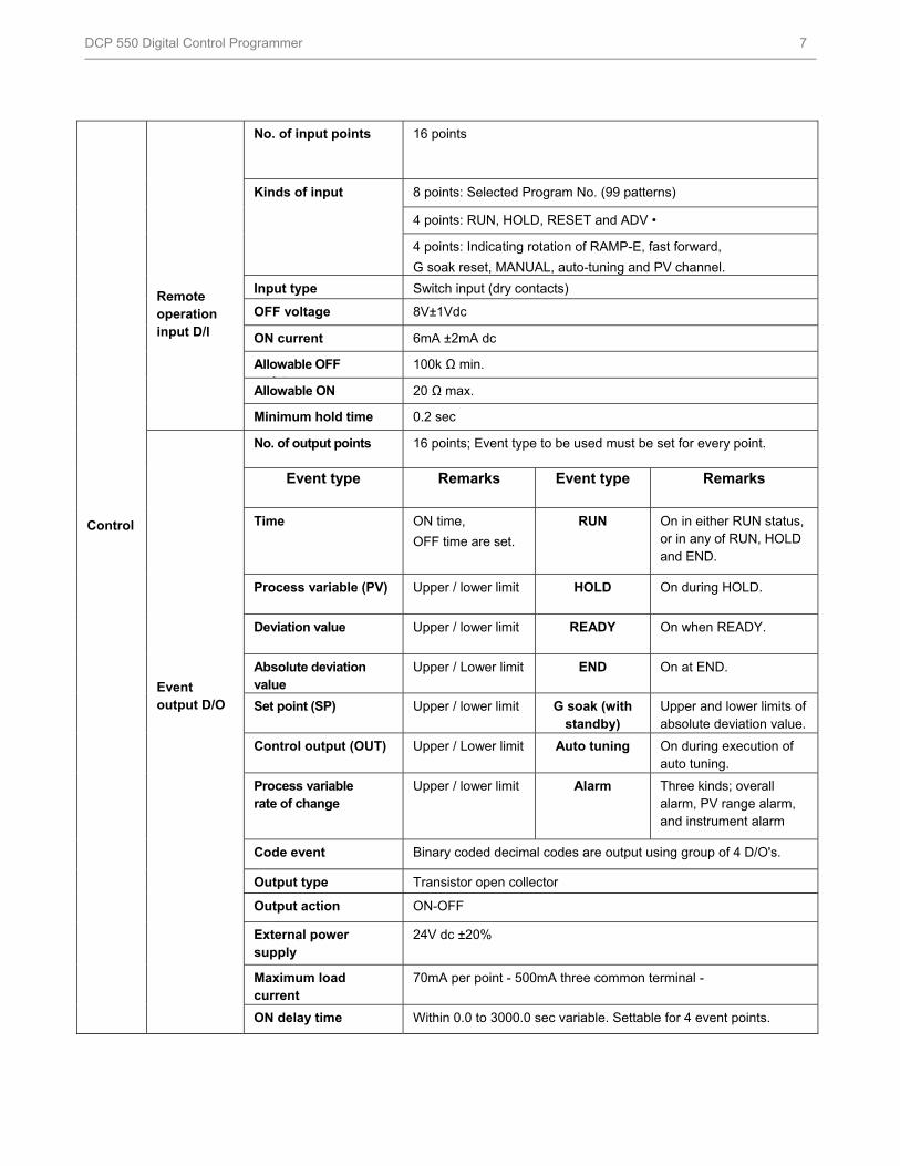
Remote operation input D/l
No. of input points 16 points
Kinds of input
8 points: Selected Program No. (99 patterns)
4 points: RUN, HOLD, RESET and ADV •
4 points: Indicating rotation of RAMP-E, fast forward,
G soak reset, MANUAL, auto-tuning and PV channel.
Input type Switch input (dry contacts)
OFF voltage 8V±1Vdc
ON current 6mA ±2mA dc
Allowable OFF i t
100k Ω min.
Allowable ON 20 Ω max.
Minimum hold time 0.2 sec
Event output D/O
No. of output points 16 points; Event type to be used must be set for every point.
Event type Remarks Event type Remarks
Time ON time,
OFF time are set.
RUN On in either RUN status, or in any of RUN, HOLD and END.
Process variable (PV) Upper / lower limit HOLD On during HOLD.
Deviation value Upper / lower limit READY On when READY.
Absolute deviation value
Upper / Lower limit END On at END.
Set point (SP) Upper / lower limit G soak (with standby)
Upper and lower limits of absolute deviation value.
Control output (OUT) Upper / Lower limit Auto tuning On during execution of auto tuning.
Process variable rate of change
Upper / lower limit Alarm Three kinds; overall alarm, PV range alarm, and instrument alarm
Code event Binary coded decimal codes are output using group of 4 D/O's.
Output type Transistor open collector
Output action ON-OFF
External power supply
24V dc ±20%
Maximum load current
70mA per point - 500mA three common terminal -
ON delay time Within 0.0 to 3000.0 sec variable. Settable for 4 event points.
HFS Catalog_Without Tab_HighRes.pdf 352 6/8/2011 12:41:19 PM
DCP 550 Digital Control Programmer 8
Control
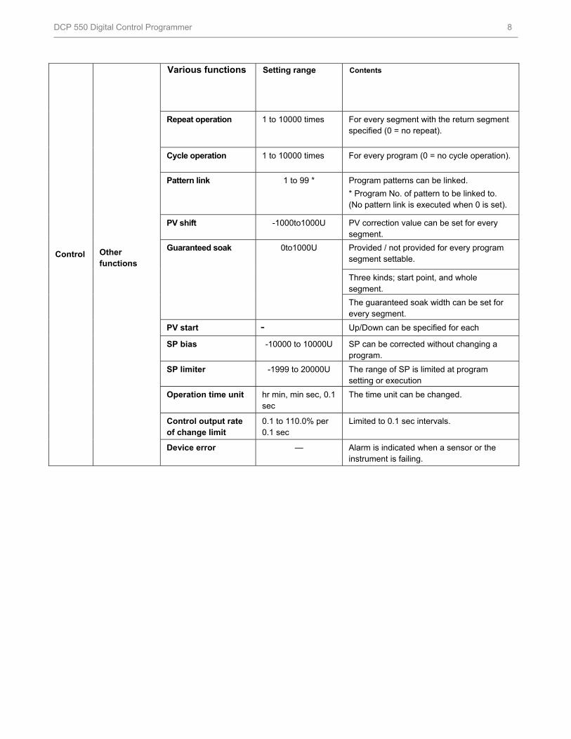
Other functions
Various functions Setting range Contents
Repeat operation 1 to 10000 times For every segment with the return segment specified (0 = no repeat).
Cycle operation 1 to 10000 times For every program (0 = no cycle operation).
Pattern link 1 to 99 * Program patterns can be linked.
* Program No. of pattern to be linked to. (No pattern link is executed when 0 is set).
PV shift -1000to1000U PV correction value can be set for every segment.
Guaranteed soak
0to1000U
Provided / not provided for every program segment settable.
Three kinds; start point, and whole segment.
The guaranteed soak width can be set for every segment.
PV start - Up/Down can be specified for each
SP bias -10000 to 10000U SP can be corrected without changing a program.
SP limiter -1999 to 20000U The range of SP is limited at program setting or execution
Operation time unit hr min, min sec, 0.1 sec
The time unit can be changed.
Control output rate of change limit
0.1 to 110.0% per 0.1 sec
Limited to 0.1 sec intervals.
Device error — Alarm is indicated when a sensor or the instrument is failing.
HFS Catalog_Without Tab_HighRes.pdf 353 6/8/2011 12:41:19 PM
DCP 550 Digital Control Programmer 9
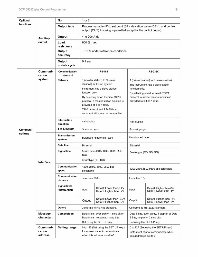
Optional functions
Auxiliary output
No. 1 or 2
Output type Process variable (PV), set point (SP), deviation value (DEV), and control output (OUT) I (scaling is permitted except for the control output).
Output 4 to 20mA dc
Load resistance
600 Ω max.
Output accuracy
+0.1 % under reference conditions
Output update cycle
0.1 sec
Communi-cations
Communi-cation system
Communication
standard
RS-485 RS-232C
Network 1 (master station) to N (slave
stations) multidrop system.
Instrument has a slave station
function only
By selecting smart terminal ST22)
protocol, a master station function is
provided at 1-to-1 ratio.
T200 protocol and RS485 host
communication are not compatible.
1 (master station) to 1 (slave station)
The instrument has a slave station
function only.
By selecting smart terminal ST221
protocol, a master station function is
provided with 1-to-1 ratio.
Information
direction Half-duplex Half-duplex
Sync, system Start-stop sync. Stan-stop sync.
Interface
Transmission
system Balanced (differential) type Unbalanced type
Data line Bit serial Bit serial
Signal line
5-wire type (SDA. SOB. RDA, RDB.
SG)3-wire type (RD, SD. SG)
3-wiretype (+,-. SG) —
Communication
speed
1200, 2400, 4800, 9600 bps
selectable 1200,2400,4800,9600 bps selectable
Communication
distance Less than 500m Less than 15m
Signal level
(differential) Input Data 0: Lower than-0.2V Data 1: Higher than +2V Input Data 0: Higher than+3V
Data 1: Lower than -3V
Output Data 0: Lower than -0.2V Data 1: Higher than +2V Output Data 0: Higher than +5V
Data 1: Lower than -5V
Others Conforms to RS-485 standard. Conforms to RS-232C standard.
Message character
Composition Data 8 bits, even parity, 1 stop bit or
Data 8 bits, no panty, 1 stop bits
Set using the SET UP key.
Data 8 bits, even panty, 1 stop bit or Data
8 Bits, no parity, 2 stop bits
Set using the SET UP key.
Communi-cation address
Setting range 0 to 127 (Set using the SET UP key.)
Instrument cannot communicate
when this address is set to0.
0 to 127 (Set using the SET UP key.)
Instrument cannot communicate when
this address is set to 0.
HFS Catalog_Without Tab_HighRes.pdf 354 6/8/2011 12:41:19 PM
DCP 550 Digital Control Programmer 10
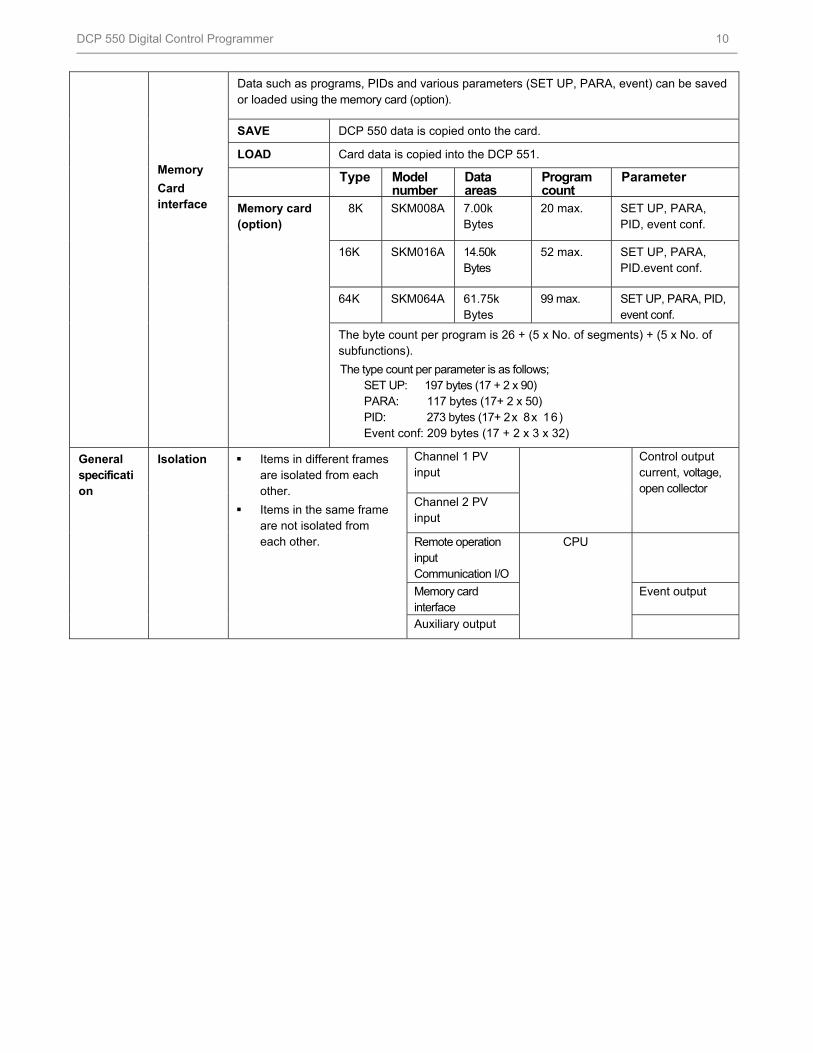
Memory
Card interface
Data such as programs, PIDs and various parameters (SET UP, PARA, event) can be saved or loaded using the memory card (option).
SAVE DCP 550 data is copied onto the card.
LOAD Card data is copied into the DCP 551.
Type Model number
Data areas
Program count
Parameter
Memory card (option)
8K SKM008A 7.00k Bytes
20 max. SET UP, PARA, PID, event conf.
16K SKM016A 14.50k Bytes
52 max. SET UP, PARA, PID.event conf.
64K SKM064A 61.75k Bytes
99 max. SET UP, PARA, PID, event conf.
The byte count per program is 26 + (5 x No. of segments) + (5 x No. of subfunctions).
The type count per parameter is as follows; SET UP: 197 bytes (17 + 2 x 90) PARA: 117 bytes (17+ 2 x 50) PID: 273 bytes (17+ 2x 8x 16) Event conf: 209 bytes (17 + 2 x 3 x 32)
General specification
Isolation
Items in different frames are isolated from each other.
Items in the same frame are not isolated from each other.
Channel 1 PV input
Control output current, voltage, open collector Channel 2 PV
input
Remote operation input Communication I/O
CPU
Memory card interface
Event output
Auxiliary output
HFS Catalog_Without Tab_HighRes.pdf 355 6/8/2011 12:41:19 PM
DCP 550 Digital Control Programmer 11
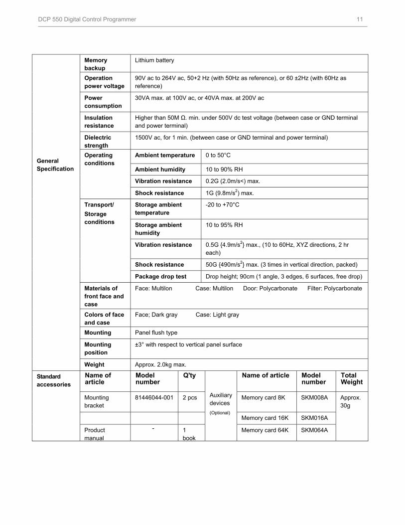
General Specification
Memory backup
Lithium battery
Operation power voltage
90V ac to 264V ac, 50+2 Hz (with 50Hz as reference), or 60 ±2Hz (with 60Hz as reference)
Power consumption
30VA max. at 100V ac, or 40VA max. at 200V ac
Insulation resistance
Higher than 50M Ω. min. under 500V dc test voltage (between case or GND terminal and power terminal)
Dielectric strength
1500V ac, for 1 min. (between case or GND terminal and power terminal)
Operating conditions
Ambient temperature 0 to 50°C
Ambient humidity 10 to 90% RH
Vibration resistance 0.2G (2.0m/s<) max.
Shock resistance 1G (9.8m/s2) max.
Transport/
Storage conditions
Storage ambient temperature
-20 to +70°C
Storage ambient humidity
10 to 95% RH
Vibration resistance 0.5G 4.9m/s2 max., (10 to 60Hz, XYZ directions, 2 hr each)
Shock resistance 50G 490m/s2 max. (3 times in vertical direction, packed)
Package drop test Drop height; 90cm (1 angle, 3 edges, 6 surfaces, free drop)
Materials of front face and case
Face: Multilon Case: Multilon Door: Polycarbonate Filter: Polycarbonate
Colors of face and case
Face; Dark gray Case: Light gray
Mounting Panel flush type
Mounting position
±3° with respect to vertical panel surface
Weight Approx. 2.0kg max.
Standard accessories
Name of article
Model number
Q'ty
Auxiliary devices
(Optional)
Name of article Model number
Total Weight
Mounting bracket
81446044-001 2 pcs Memory card 8K SKM008A Approx. 30g
Memory card 16K SKM016A
Product manual
- 1 book
Memory card 64K SKM064A
HFS Catalog_Without Tab_HighRes.pdf 356 6/8/2011 12:41:19 PM
DCP 550 Digital Control Programmer 12
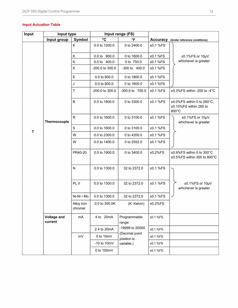
Input Actuation Table Input t
Input type Input range (FS)
Input group Symbol °C °F Accuracy (Under reference conditions)
T
Thermocouple
K 0.0 to 1200.0 0 to 2400.0 ±0.1 %FS
±0.1%FS or 10µV whichever is greater
K 0.0 to 800.0 0 to 1600.0 ±0.1 %FS
K 0.0 to 400.0 0 to 750.0 ±0.1 %FS
K -200.0 to 300.0 -300 to 400.0 ±0.1 %FS
E 0.0 to 800.0 0 to 1800.0 ±0.1 %FS
J 0.0 to 800.0 0 to 1600.0 ±0.1 %FS
T -200.0 to 300.0 -300.0 to 700.0 ±0.1 %FS ±0.3%FS within -200 to -4°C
B 0.0 to 1800.0 0 to 3300.0 ±0.1 %FS ±4.0%FS within 0 to 260°C, ±0.15%FS within 260 to 800°C
R 0.0 to 1600.0 0 to 3100.0 ±0.1 %FS ±0.1%FS or 10µV whichever is greater
S 0.0 to 1600.0 0 to 3100.0 ±0.1 %FS
W 0.0 to 2300.0 0 to 4200.0 ±0.1 %FS
W 0.0 to 1400.0 0 to 2552.0 ±0.1 %FS
PR40-20 0.0 to 1900.0 0 to 3400.0 ±0.2%FS ±0.9%FS within 0 to 300°C ±0.5%FS within 300 to 800°C
N 0.0 to 1300.0 32 to 2372.0 ±0.1 %FS
PL II 0.0 to 1300.0 32 to 2372.0 ±0.1 %FS ±0.1%FS or 10µV whichever is greater
Ni-Ni • Mo 0.0 to 1300.0 32 to 2372.0 ±0.1 %FS
Alloy iron chromel
0.0 to 300.0K (K: Kelvin) ±0.2%FS
Voltage and current
mA 4 to 20mA Programmable
range:
-19999 to 20000
(Decimal point
position is variable.)
±0.1 %FS
2.4 to 20mA ±0.1 %FS
mV 0 to 10mV ±0.1 %FS
-10 to 10mV ±0.1 %FS
0 to 100mV ±0.1 %FS
HFS Catalog_Without Tab_HighRes.pdf 357 6/8/2011 12:41:19 PM
DCP 550 Digital Control Programmer 13
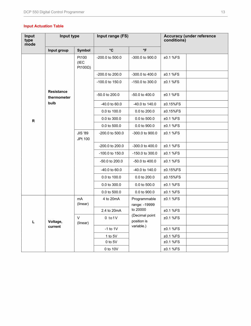
Input Actuation Table Input type mode
Input type Input range (FS) Accuracy (under reference conditions)
Input group Symbol °C °F
R
Resistance
thermometer
bulb
Pt100 (IEC Pt100Ω)
-200.0 to 500.0 -300.0 to 900.0 ±0.1 %FS
-200.0 to 200.0 -300.0 to 400.0 ±0.1 %FS
-100.0 to 150.0 -150.0 to 300.0 ±0.1 %FS
-50.0 to 200.0 -50.0 to 400.0 ±0.1 %FS
-40.0 to 60.0 -40.0 to 140.0 ±0.15%FS
0.0 to 100.0 0.0 to 200.0 ±0.15%FS
0.0 to 300.0 0.0 to 500.0 ±0.1 %FS
0.0 to 500.0 0.0 to 900.0 ±0.1 %FS
JIS '89
JPt 100
-200.0 to 500.0 -300.0 to 900.0 ±0.1 %FS
-200.0 to 200.0 -300.0 to 400.0 ±0.1 %FS
-100.0 to 150.0 -150.0 to 300.0 ±0.1 %FS
-50.0 to 200.0 -50.0 to 400.0 ±0.1 %FS
-40.0 to 60.0 -40.0 to 140.0 ±0.15%FS
0.0 to 100.0 0.0 to 200.0 ±0.15%FS
0.0 to 300.0 0.0 to 500.0 ±0.1 %FS
0.0 to 500.0 0.0 to 900.0 ±0.1 %FS
L
Voltage, current
mA (linear)
4 to 20mA Programmable
range: -19999 to 20000
(Decimal point
position is variable.)
±0.1 %FS
2.4 to 20mA ±0.1 %FS
V (linear)
0 to1V ±0.1 %FS
-1 to 1V ±0.1 %FS
1 to 5V ±0.1 %FS 0 to 5V ±0.1 %FS
0 to 10V ±0.1 %FS
HFS Catalog_Without Tab_HighRes.pdf 358 6/8/2011 12:41:19 PM
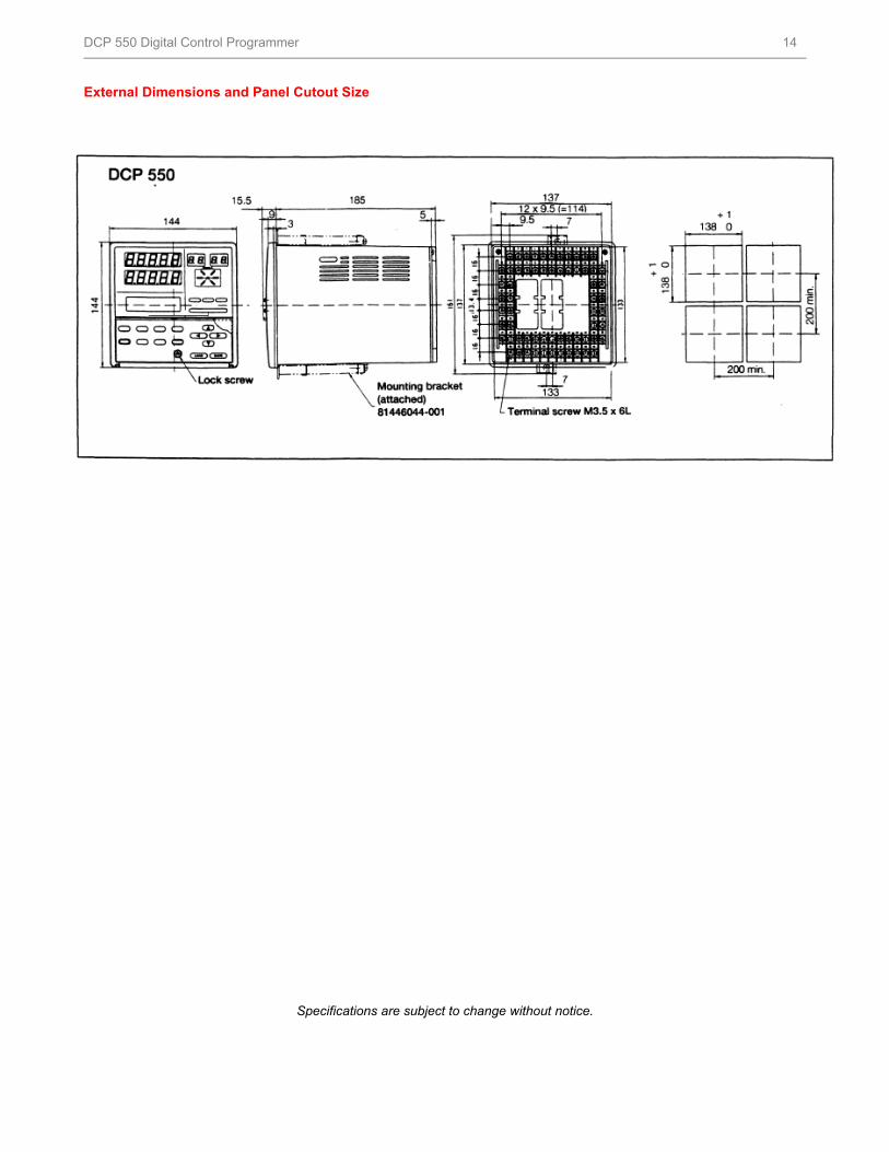
DCP 550 Digital Control Programmer 14
External Dimensions and Panel Cutout Size
Specifications are subject to change without notice.
HFS Catalog_Without Tab_HighRes.pdf 359 6/8/2011 12:41:19 PM
DCP 550 Digital Control Programmer 15
For More Information
Learn more about how Honeywell’s DCP 550 Digital
Control Programmer combines superior functionality,
quality and reliability, visit our website
www.honeywell.com/ps/hfs or contact your Honeywell
account manager.
Honeywell Process Solutions
1860 West Rose Garden Lane
Phoenix, Arizona 85027
Tel: 1-800-423-9883 or 1-800-343-0228 www.honeywell.com/ps
57-77-03-12February 1995 © 2010 Honeywell International Inc.
HFS Catalog_Without Tab_HighRes.pdf 360 6/8/2011 12:41:19 PM