Embed Size (px)
Citation preview
INS
TR
UC
TIO
N M
AN
UA
L
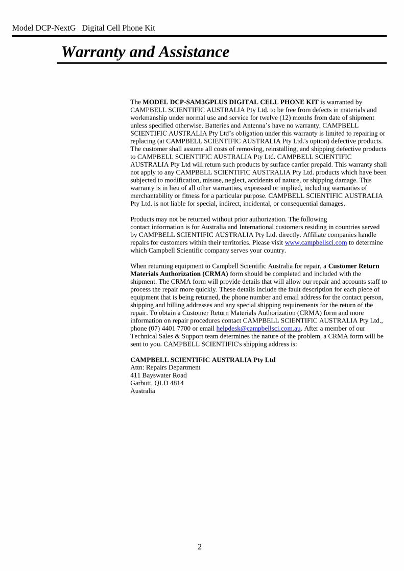
DCP-NextG
Digital Cell Phone Kit
Maxon ModMax MM-6280IND Revision: Dec 2012
Copyright © 1990 - 2007
Campbell Scientific Australia Pty Ltd
Model DCP-NextG Digital Cell Phone Kit
2
Warranty and Assistance
The MODEL DCP-SAM3GPLUS DIGITAL CELL PHONE KIT is warranted by
CAMPBELL SCIENTIFIC AUSTRALIA Pty Ltd. to be free from defects in materials and
workmanship under normal use and service for twelve (12) months from date of shipment
unless specified otherwise. Batteries and Antenna’s have no warranty. CAMPBELL
SCIENTIFIC AUSTRALIA Pty Ltd’s obligation under this warranty is limited to repairing or
replacing (at CAMPBELL SCIENTIFIC AUSTRALIA Pty Ltd.'s option) defective products.
The customer shall assume all costs of removing, reinstalling, and shipping defective products
to CAMPBELL SCIENTIFIC AUSTRALIA Pty Ltd. CAMPBELL SCIENTIFIC
AUSTRALIA Pty Ltd will return such products by surface carrier prepaid. This warranty shall
not apply to any CAMPBELL SCIENTIFIC AUSTRALIA Pty Ltd. products which have been
subjected to modification, misuse, neglect, accidents of nature, or shipping damage. This
warranty is in lieu of all other warranties, expressed or implied, including warranties of
merchantability or fitness for a particular purpose. CAMPBELL SCIENTIFIC AUSTRALIA
Pty Ltd. is not liable for special, indirect, incidental, or consequential damages.
Products may not be returned without prior authorization. The following
contact information is for Australia and International customers residing in countries served
by CAMPBELL SCIENTIFIC AUSTRALIA Pty Ltd. directly. Affiliate companies handle
repairs for customers within their territories. Please visit www.campbellsci.com to determine
which Campbell Scientific company serves your country.
When returning equipment to Campbell Scientific Australia for repair, a Customer Return
Materials Authorization (CRMA) form should be completed and included with the
shipment. The CRMA form will provide details that will allow our repair and accounts staff to
process the repair more quickly. These details include the fault description for each piece of
equipment that is being returned, the phone number and email address for the contact person,
shipping and billing addresses and any special shipping requirements for the return of the
repair. To obtain a Customer Return Materials Authorization (CRMA) form and more
information on repair procedures contact CAMPBELL SCIENTIFIC AUSTRALIA Pty Ltd.,
phone (07) 4401 7700 or email [email protected]. After a member of our
Technical Sales & Support team determines the nature of the problem, a CRMA form will be
sent to you. CAMPBELL SCIENTIFIC's shipping address is:
CAMPBELL SCIENTIFIC AUSTRALIA Pty Ltd Attn: Repairs Department
411 Bayswater Road
Garbutt, QLD 4814
Australia
Model DCP-NextG Digital Cell Phone Kit
3
Table of Contents
1 Network Coverage .......................................................................................................................... 5
2 Specifications ................................................................................................................................... 5
3 Getting Connected – Circuit Switched Data ................................................................................. 6
4 Modem Overview ............................................................................................................................ 7
5 Data Logger Port Connection ........................................................................................................ 7
5.1 RS-232 vs CS I/O ........................................................................................ 7
5.2 Datalogger I/O Ports ................................................................................... 8
5.3 Connection via CS I/O port ......................................................................... 9
5.3.1 SC105 Interface .......................................................................................... 11
5.4 Connection via RS232 port ....................................................................... 14
6 Power Considerations ................................................................................................................... 15
6.1 Current Requirements ............................................................................... 15
6.2 Switched Power ........................................................................................ 15
6.2.1 SW12 and Remote Program Upload ........................................................... 15
7 SAM3G+ Configuration ............................................................................................................... 16
7.1 Hardware ................................................................................................... 16
7.2 Software .................................................................................................... 17
7.2.1 SAM 3G+ Settings ...................................................................................... 17
7.2.2 PC Modem Requirements ........................................................................... 19
7.2.3 Data Logger Settings ................................................................................... 19
8 SMS ................................................................................................................................................ 20
8.1 Example Program ...................................................................................... 21
9 Advanced Communications ......................................................................................................... 22
10 Troubleshooting ............................................................................................................................ 23
Model DCP-NextG Digital Cell Phone Kit
4
Figures FIGURE 4-1 SAM3G+ MODEM ....................................................................................................................................................................... 7 FIGURE 5-1 MODEM CONNECTION TO DATA LOGGER CS I/O PORT ................................................................................................................... 9 FIGURE 5-2 SC105 CONNECTION VIA DEVICE CONFIGURATION UTILITY .......................................................................................................... 11 FIGURE 5-3 SC105 DEPLOYMENT CONFIGURATION ......................................................................................................................................... 12 FIGURE 5-4 MODEM CONNECTION TO DATA LOGGER RS232 PORT .................................................................................................................. 14 FIGURE 7-1 DEVICE CONFIGURATION UTILITY CONNECTION TO SAM3G+ ...................................................................................................... 17 FIGURE 7-2 PUTTY CONNECTION TO SAM3G+ .............................................................................................................................................. 18
Tables TABLE 5-1 DATALOGGER 9-PIN I/O PORTS ....................................................................................................................................................... 8 TABLE 5-2 PARTS SUPPLIED WITH CS I/O MODEM KIT ...................................................................................................................................... 9 TABLE 5-3 SC105 CONFIGURATION SETTINGS ................................................................................................................................................ 12 TABLE 5-4 PARTS SUPPLIED WITH RS232 MODEM KIT .................................................................................................................................... 14 TABLE 7-1 AT COMMANDS TO CHANGE REQUIRED SETTINGS IN SAM3G+ ....................................................................................................... 18 TABLE 8-1 SIMPLE AT COMMANDS FOR SMS .................................................................................................................................................. 20
Model DCP-NextG Digital Cell Phone Kit
5
Model DCP-NextG Digital Cell Phone Kit
1 Network Coverage One of the main advantages of using a cellular telephone network is being able to set up a
communications link to a data logger virtually anywhere without installing telephone lines.
However, this only applies if your installation site is covered by a suitable NextG network.
Before purchasing a NextG modem it is recommended that the coverage is tested on site by
using a NextG handset with the same service provider, and measuring the exact signal
strength.
Though this manual focuses on use of the SAM 3G+ modem kit with Telstra’s NextG service,
the SAM 3G+ is compatible with all 3G and GSM frequency bands including those used by
Optus, Vodafone and their resellers.
Coverage maps are available from the service providers. Please note however that even
though an area is shown as covered on the map, it is important to check the signal strength on
site because it may be that the location has poor coverage due to interference or other
technical reasons.
As with any network based on radio technology, some local conditions may prevent or
interfere with mobile phone reception within coverage areas. Such conditions may include
concrete buildings, lift wells, below ground basements, tunnels, mountains and road cuttings.
2 Specifications Operating Temperature: -20°C to +60°C
Supply Voltage: 5 to 32 VDC
Power Consumption (12V): Average 250mA using 3G
Average 205mA using 2G
30mA in standby
Antenna: SMB Male 50Ω SMB Male – FME Female connector supplied.
Other Interfaces: RS232 and Power via RJ45 Connector, USB for PC Interface
Dimensions: 74mm x 45mm x 24mm
Weight: 56g (without antennas)
Frequency Bands: UMTS/HSPA (3G) 850MHz, 1900MHz, 2100MHz
GPRS/EDGE (2G) 850MHz, 900MHz, 1800MHz, 1900MHz
See Table 5-1 for a list of the parts supplied with our CS I/O kit
See Table 5-4 for a list of the parts supplied with our CS I/O kit

Model DCP-NextG Digital Cell Phone Kit
6
3 Getting Connected – Circuit Switched Data The NextG modem is sold without an airtime agreement. The user must arrange connection of
the modem to a network and have it enabled for data use. The service provider will supply a
Subscriber Identification Module (SIM), which is inserted into the SAM3G+ and acts as a key
to enable its use.
When setting up the account, the service provider may require some information such as the
make and model of the modem being used. They will then set up an account and provide a
phone number. This phone number is a voice number. However, voice is not supported in the
SAM3G+, and it is not possible for the data logger to receive data calls (circuit switched data)
with a voice number.
A data number is required for circuit switched data and SMS transmissions to the data
logger. The service provider will need to know this information when setting up the account
and enabling the SIM card. Telstra will need to know that you require a Data Terminating
Number. Furthermore, ensure that Bearer Code 2620 is activated on your account. Bearer
code 2620 is Telstra’s code for data service on NextG. This can be done through the Telstra
Business Centre or a suitable reseller of Telstra data services. Telstra Shop employees are not
trained in industrial modem use and cannot help you set up a Data Terminating Number.
There are options that can be specified to reduce complexity and cost of the service. You can
remove all ancillary services such as Call Waiting, Call Diversion and Message Bank as these
are not required.
If the unit is set up with a security code or pin number, it should be disabled before use with
the Campbell Scientific data logger. The security code or pin number can be disabled by
putting the SIM card into a normal digital mobile phone and select the security menu. Exact
key presses will depend on the mobile phone used, but from this menu it should be possible to
disable the PIN.
If you experience difficulty getting Circuit Switched Data enabled for your SIM card, contact
Campbell Scientific Australia.
THE SIM CARD MUST NOT BE REMOVED WHILE THE UNIT IS POWERED UP.
THIS MAY RESULT IN DAMAGE TO THE MODEM AND/OR SIM CARD.
Note: Some users may have experienced reliability problems when calling a NextG modem
on the Telstra network from a non-Telstra telephone line. Please see Section 7, on
Troubleshooting for more information.
Model DCP-NextG Digital Cell Phone Kit
7
4 Modem Overview
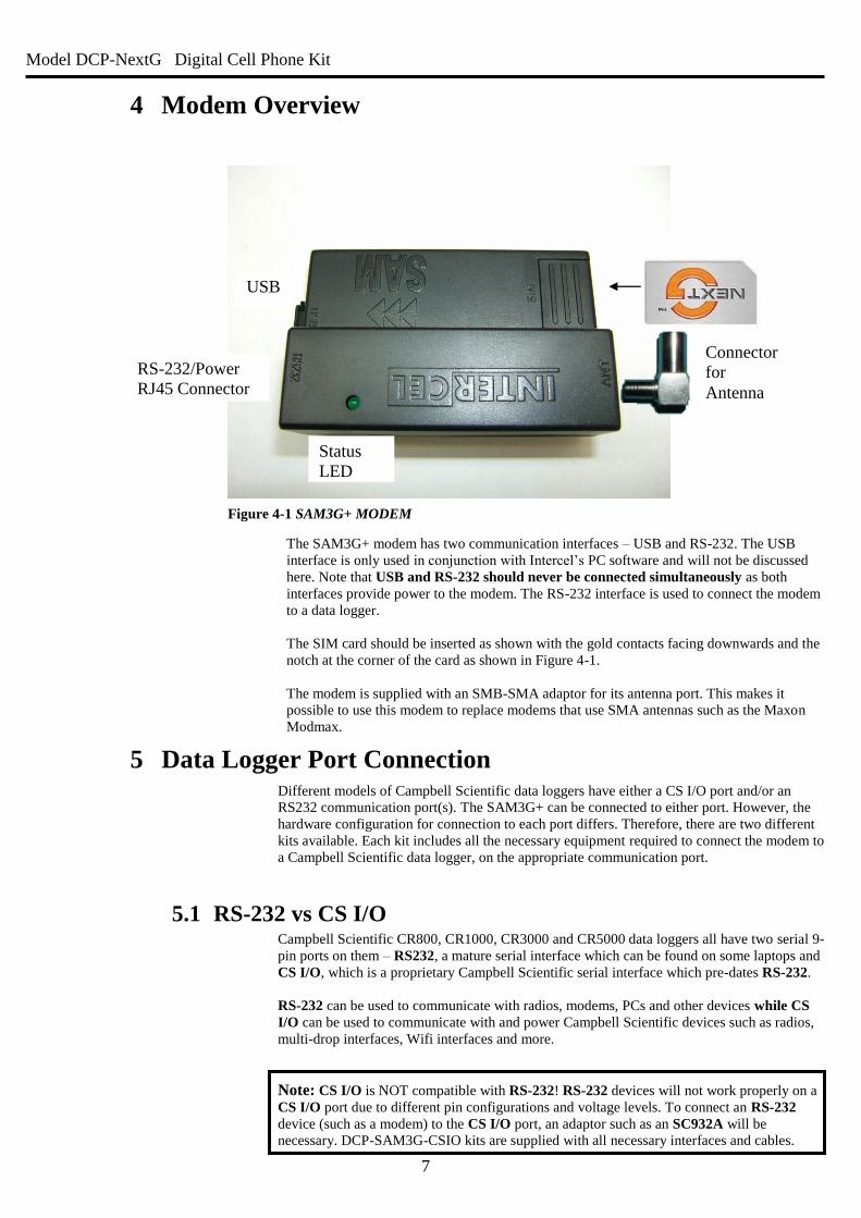
The SAM3G+ modem has two communication interfaces – USB and RS-232. The USB
interface is only used in conjunction with Intercel’s PC software and will not be discussed
here. Note that USB and RS-232 should never be connected simultaneously as both
interfaces provide power to the modem. The RS-232 interface is used to connect the modem
to a data logger.
The SIM card should be inserted as shown with the gold contacts facing downwards and the
notch at the corner of the card as shown in Figure 4-1.
The modem is supplied with an SMB-SMA adaptor for its antenna port. This makes it
possible to use this modem to replace modems that use SMA antennas such as the Maxon
Modmax.
5 Data Logger Port Connection Different models of Campbell Scientific data loggers have either a CS I/O port and/or an
RS232 communication port(s). The SAM3G+ can be connected to either port. However, the
hardware configuration for connection to each port differs. Therefore, there are two different
kits available. Each kit includes all the necessary equipment required to connect the modem to
a Campbell Scientific data logger, on the appropriate communication port.
5.1 RS-232 vs CS I/O Campbell Scientific CR800, CR1000, CR3000 and CR5000 data loggers all have two serial 9-
pin ports on them – RS232, a mature serial interface which can be found on some laptops and
CS I/O, which is a proprietary Campbell Scientific serial interface which pre-dates RS-232.
RS-232 can be used to communicate with radios, modems, PCs and other devices while CS
I/O can be used to communicate with and power Campbell Scientific devices such as radios,
multi-drop interfaces, Wifi interfaces and more.
Note: CS I/O is NOT compatible with RS-232! RS-232 devices will not work properly on a
CS I/O port due to different pin configurations and voltage levels. To connect an RS-232
device (such as a modem) to the CS I/O port, an adaptor such as an SC932A will be
necessary. DCP-SAM3G-CSIO kits are supplied with all necessary interfaces and cables.
USB
RS-232/Power
RJ45 Connector
Connector
for
Antenna
Status
LED
Figure 4-1 SAM3G+ MODEM
Model DCP-NextG Digital Cell Phone Kit
8
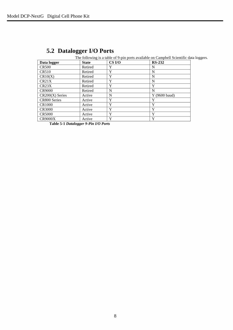
5.2 Datalogger I/O Ports The following is a table of 9-pin ports available on Campbell Scientific data loggers.
Data logger State CS I/O RS-232
CR500 Retired Y N
CR510 Retired Y N
CR10(X) Retired Y N
CR21X Retired Y N
CR23X Retired Y Y
CR9000 Retired N N
CR200(X) Series Active N Y (9600 baud)
CR800 Series Active Y Y
CR1000 Active Y Y
CR3000 Active Y Y
CR5000 Active Y Y
CR9000X Active Y Y
Table 5-1 Datalogger 9-Pin I/O Ports
Model DCP-NextG Digital Cell Phone Kit
9
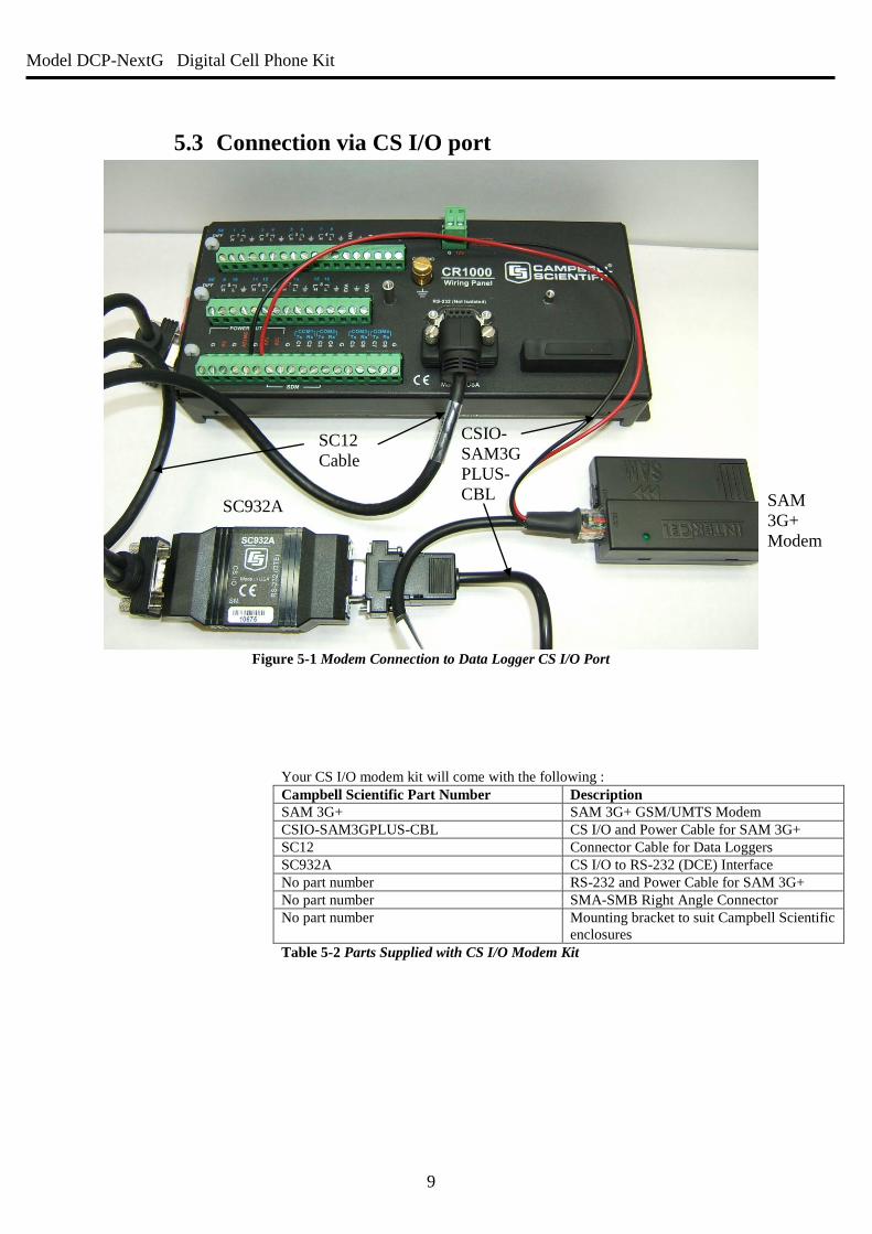
5.3 Connection via CS I/O port
Figure 5-1 Modem Connection to Data Logger CS I/O Port
Your CS I/O modem kit will come with the following :
Campbell Scientific Part Number Description
SAM 3G+ SAM 3G+ GSM/UMTS Modem
CSIO-SAM3GPLUS-CBL CS I/O and Power Cable for SAM 3G+
SC12 Connector Cable for Data Loggers
SC932A CS I/O to RS-232 (DCE) Interface
No part number RS-232 and Power Cable for SAM 3G+
No part number SMA-SMB Right Angle Connector
No part number Mounting bracket to suit Campbell Scientific
enclosures Table 5-2 Parts Supplied with CS I/O Modem Kit
SAM
3G+
Modem
CSIO-
SAM3G
PLUS-
CBL SC932A
SC12
Cable
Model DCP-NextG Digital Cell Phone Kit
10
To connect a new CS I/O modem kit to a data logger, follow these steps:
Connect the black DCP-SAM3GPLUS-CBL’s square RJ45 connector to the socket
on the modem.
Connect the two tinned wires on this cable to the data logger. The red wire connects
to 12V and the black wire to the G terminal. The SW12 terminal can be used instead
of 12V however since it is a switched supply it needs to be enabled in the
datalogger program to function correctly.
Note that SW12 is a switched 12V supply and needs to be enabled in the data logger
program to function.
Insert the 9-pin end of the DCP-SAM3GPLUS-CBL into the RS-232 (DCE)
connector on the SC932A.
Finally, connect the male end of the SC12 cable to the logger’s CS I/O port and one
of the female ends (doesn’t matter which) to the CS I/O connector the SC932A
Ensure that the SC932A interface is connected correctly!
It is easy to connect the SC932A the wrong way around – it will not work unless the DCE
Device end is connected to the modem and the Datalogger end is connected to the logger’s
CS I/O port.
The CSIO-SAM3GPLUS-CBL cable must be used between the SC932A device and the
modem for successful communication between the data logger and the modem. The
manufacturer’s beige interface cable with the female RS-232 connector is not suitable for this
connection.
Model DCP-NextG Digital Cell Phone Kit
11
5.3.1 SC105 Interface In order to connect via the CS I/O port of the data logger a serial interface is required.
Generally a SC932A RS-232 interface is supplied, however in some cases the alternate SC105
RS-232 interface may be used due to the customer preference or the requirements of the
system.
The SC105 is a more advanced device than the SC932A as it contains more user-definable
settings which allow the interface between the modem and logger to be specifically
configured and controlled. The following section relates to using the SC105 interface.
In order for the SC105 to work effectively with the SAM3G+ modem, the SC105 default
settings will need to be slightly modified. To change these settings, we recommend using
Campbell Scientific’s Device Configuration Utility, available from
https://www.campbellsci.com/downloads. If desired, configuration changes can also be made
using a terminal emulator package and the SC105’s built in menus.
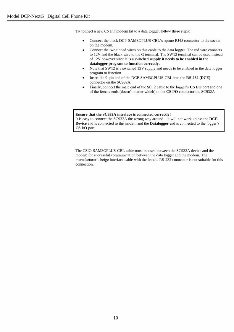
Figure 5.2 Connection to SC105 using Device Configuration Utility
To configure the SC105 using Device Configuration Utility, first connect the female-female
null modem cable supplied with the SC105 to your PC’s serial port and the Modem connector
on the SC105. Next, provide power to the SC105 by connecting the SC12 cable supplied to
the SC105’s Datalogger connector and the CS I/O port of a datalogger. Once this is done,
open Device Configuration Utility, expand the Peripheral section if available and select
SC105. Check that the Communications Port selected is the one that you have connected to
the SC105, press the green program button on the SC105, then press Connect in Device
Configuration Utility.
Figure 5-2 SC105 Connection via Device Configuration Utility
Model DCP-NextG Digital Cell Phone Kit
12
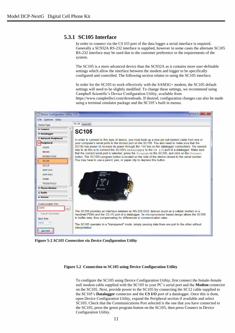
In the Deployment tab, select the following settings:
Field Value
CS I/O Mode Modem Enable
CS I/O Baud Rate 115.2k
RS-232 Mode PC/PDA
Baud Rate 115.2k
Table 5-3 SC105 Configuration Settings
Once this is done, click Apply. Connect to the SC105 again and select the Settings Editor Tab.
Change the RS-232 Auto Power Down setting to “RS-232 Always Active to power RS-232
devices” and click Apply again. Your SC105 is now configured for use with a DCP-
SAM3GPLUS-CSIO modem kit.
Figure 5-3 SC105 Deployment Configuration
Model DCP-NextG Digital Cell Phone Kit
13
To access the menus using Hyperterminal, establish a connection between the serial port and
the SC105 using the null-modem cable (included with the SC105). The port settings for this
connection should be 9600-8-N-1.
Press the green programming button on the side of the SC105 and the menus will appear in
the terminal window.
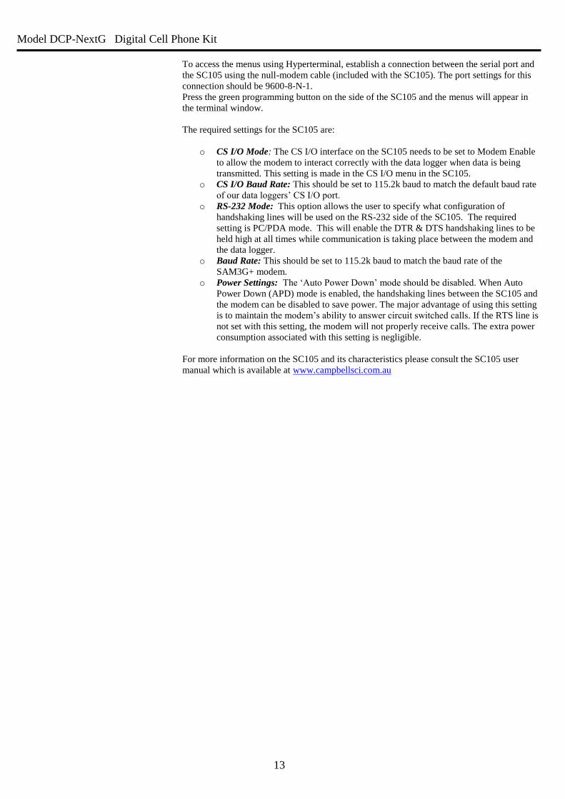
The required settings for the SC105 are:
o CS I/O Mode: The CS I/O interface on the SC105 needs to be set to Modem Enable
to allow the modem to interact correctly with the data logger when data is being
transmitted. This setting is made in the CS I/O menu in the SC105.
o CS I/O Baud Rate: This should be set to 115.2k baud to match the default baud rate
of our data loggers’ CS I/O port.
o RS-232 Mode: This option allows the user to specify what configuration of
handshaking lines will be used on the RS-232 side of the SC105. The required
setting is PC/PDA mode. This will enable the DTR & DTS handshaking lines to be
held high at all times while communication is taking place between the modem and
the data logger.
o Baud Rate: This should be set to 115.2k baud to match the baud rate of the
SAM3G+ modem.
o Power Settings: The ‘Auto Power Down’ mode should be disabled. When Auto
Power Down (APD) mode is enabled, the handshaking lines between the SC105 and
the modem can be disabled to save power. The major advantage of using this setting
is to maintain the modem’s ability to answer circuit switched calls. If the RTS line is
not set with this setting, the modem will not properly receive calls. The extra power
consumption associated with this setting is negligible.
For more information on the SC105 and its characteristics please consult the SC105 user
manual which is available at www.campbellsci.com.au
Model DCP-NextG Digital Cell Phone Kit
14
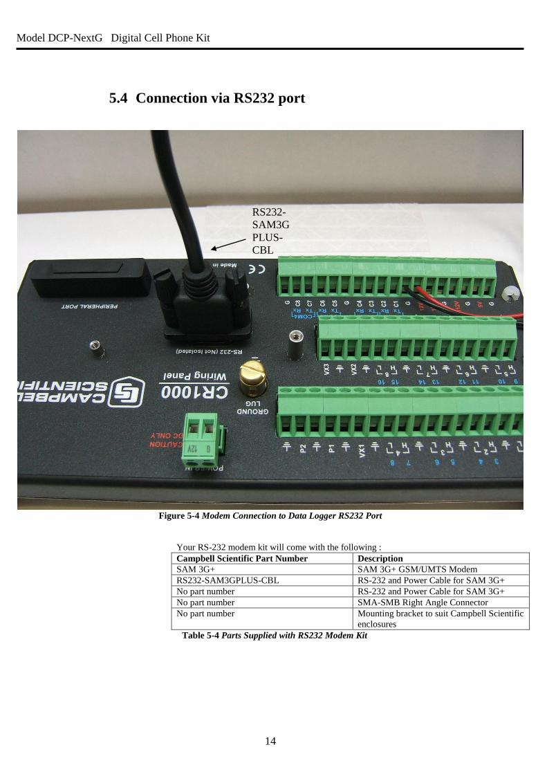
5.4 Connection via RS232 port
Figure 5-4 Modem Connection to Data Logger RS232 Port
Your RS-232 modem kit will come with the following :
Campbell Scientific Part Number Description
SAM 3G+ SAM 3G+ GSM/UMTS Modem
RS232-SAM3GPLUS-CBL RS-232 and Power Cable for SAM 3G+
No part number RS-232 and Power Cable for SAM 3G+
No part number SMA-SMB Right Angle Connector
No part number Mounting bracket to suit Campbell Scientific
enclosures Table 5-4 Parts Supplied with RS232 Modem Kit
RS232-
SAM3G
PLUS-
CBL
Model DCP-NextG Digital Cell Phone Kit
15
6 Power Considerations
6.1 Current Requirements Because of the transmitting current drain of the Intercel SAM 3G+, the length and frequency
of both incoming and outgoing calls should be considered when determining the best power
supply for your system:
o Where pre-determined call intervals are short and infrequent (e.g.: 10 minutes per
day), the system can typically be powered by sealed rechargeable batteries
supplemented by a charging source (AC power or solar panel)
o For longer calls or more frequent time intervals (e.g.: 20 to 30 minutes every hour), a
deep-cycle battery trickle-charged by AC power would be a better option for powering
the system.
o When communications between the data logger and the computer must be available
for long periods of time, AC power may be required.
Use the current consumption numbers in Specifications (section 2) to calculate the power
consumption of your modem and the size of battery, solar panel and charging regulator that
you will require.
6.2 Switched Power In an effort to conserve power, power to the modem can be switched on and off at different
times or under certain circumstances by utilizing the Switched 12V supply or by using an
external relay circuit. Details of an external relay circuit can be found in the installation
section of your data logger manual. Common configurations include having the modem
switch on for 10 minutes per hour or switching the modem off during night time in solar
powered systems.
Switched 12V power can be supplied by the data logger on its SW12 channel. Note that this
output is controlled by the datalogger program and is disabled by default – a modem plugged
into an unconfigured data logger’s SW12 will be unpowered. In order to use SW12, the
logger’s program must be written to switch the power on and off using the SW12() instruction
in CRBasic.
6.2.1 SW12 and Remote Program Upload Please exercise caution when loading new programs over the modem link if the modem is
powered by SW12. If the new program is not properly configured, this can cause the modem
to lose power and the station may no longer be contactable.
One good way to avoid this situation is to insert a SW12(1) statement in your CRBasic
program between the BeginProg and Scan() statements – this will ensure that one of the first
things the logger will do after receiving its new program is power on the modem.
Model DCP-NextG Digital Cell Phone Kit
16
7 SAM3G+ Configuration
7.1 Hardware As discussed above, the modem can be powered in a number of ways. The power supply
wires can be connected directly to battery terminals, to the logger 12V or SW12V supplies or
to some external relay circuit. If the modem is to be switched on and off via a relay or the
SW12V supply of a data logger, the control of switching the power supply on and off can be
performed by the user program in the data logger. See the data logger manual for details of
using the switched 12V supply.
For most situations, a 3dB antenna will be suitable for remote operation. In low signal areas
however, a 6.5dB antenna may be necessary.
The Intercel SAM 3G+ is supplied with a mounting bracket for connection to environmental
enclosures. The modem can be easily removed from this bracket if necessary. This bracket has
been modified to suit Campbell Scientific enclosure backplanes.
Model DCP-NextG Digital Cell Phone Kit
17
7.2 Software
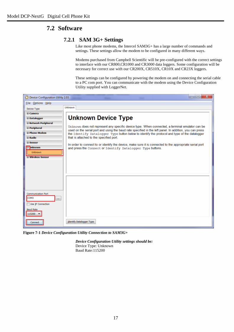
7.2.1 SAM 3G+ Settings Like most phone modems, the Intercel SAM3G+ has a large number of commands and
settings. These settings allow the modem to be configured in many different ways.
Modems purchased from Campbell Scientific will be pre-configured with the correct settings
to interface with our CR800,CR1000 and CR3000 data loggers. Some configuration will be
necessary for correct use with our CR200X, CR510X, CR10X and CR23X loggers.
These settings can be configured by powering the modem on and connecting the serial cable
to a PC com port. You can communicate with the modem using the Device Configuration
Utility supplied with LoggerNet.
Device Configuration Utility settings should be:
Device Type: Unknown
Baud Rate:115200
Figure 7-1 Device Configuration Utility Connection to SAM3G+
Model DCP-NextG Digital Cell Phone Kit
18
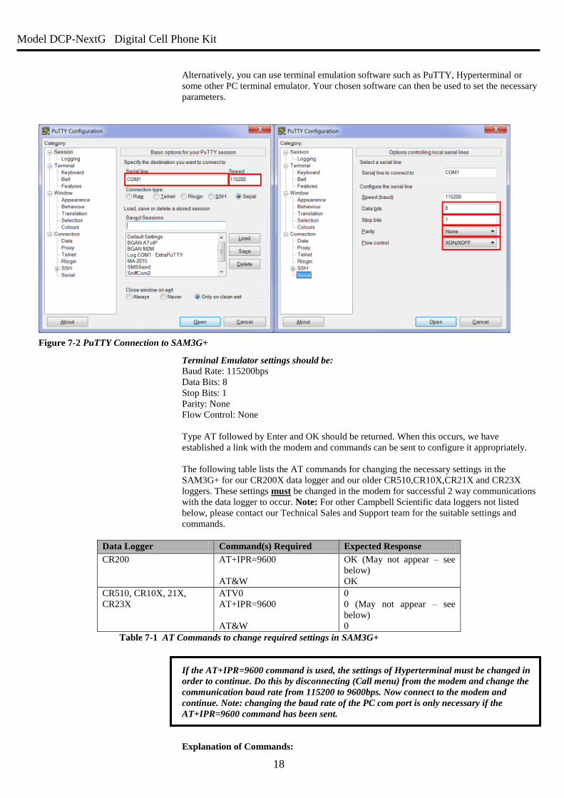
Alternatively, you can use terminal emulation software such as PuTTY, Hyperterminal or
some other PC terminal emulator. Your chosen software can then be used to set the necessary
parameters.
Terminal Emulator settings should be:
Baud Rate: 115200bps
Data Bits: 8
Stop Bits: 1
Parity: None
Flow Control: None
Type AT followed by Enter and OK should be returned. When this occurs, we have
established a link with the modem and commands can be sent to configure it appropriately.
The following table lists the AT commands for changing the necessary settings in the
SAM3G+ for our CR200X data logger and our older CR510,CR10X,CR21X and CR23X
loggers. These settings must be changed in the modem for successful 2 way communications
with the data logger to occur. Note: For other Campbell Scientific data loggers not listed
below, please contact our Technical Sales and Support team for the suitable settings and
commands.
Data Logger Command(s) Required Expected Response
CR200 AT+IPR=9600
AT&W
OK (May not appear – see
below)
OK
CR510, CR10X, 21X,
CR23X
ATV0
AT+IPR=9600
AT&W
0
0 (May not appear – see
below)
0
Table 7-1 AT Commands to change required settings in SAM3G+
If the AT+IPR=9600 command is used, the settings of Hyperterminal must be changed in
order to continue. Do this by disconnecting (Call menu) from the modem and change the
communication baud rate from 115200 to 9600bps. Now connect to the modem and
continue. Note: changing the baud rate of the PC com port is only necessary if the
AT+IPR=9600 command has been sent.
Explanation of Commands:
Figure 7-2 PuTTY Connection to SAM3G+
Model DCP-NextG Digital Cell Phone Kit
19
+IPR=9600 : Baud Rate control. The CR200, and Array-based data loggers, such as
the CR510 and CR10X, are limited to 9600 baud communications. This command limits the
terminal communications speed to 9600 baud from its default of 115200. The response to this
command may not be visible as it may be returned at 9600 baud while the terminal emulator
is set to 115200. It is for this reason that the terminal emulator must be reconfigured to 9600
baud to match the modem in order to send mode commands. This parameter is automatically
stored in the non-volatile memory of the modem, so it will be retained during a power up.
This command is not required when using Pakbus-based data loggers (except the CR200) as
they will (by default) interface to the SAM3G+ modem at 115200 baud.
&W : Save to power up profile. This command saves the current configuration. This
should be done so the modem retains the settings when power-cycled.
NOTE ON AT&W: Some modems make use of the AT&F command. Do not use this
command with the SAM3GPLUS as it will reset the SMS mode, preventing SMS
messages from being sent or received correctly.
7.2.2 PC Modem Requirements There are 3 connections in a modem link.
1. PC to Modem1
2. Modem1 to Modem2
3. Modem2 to Data logger
These connections do not have to be at the same speed. The AT+IPR = 9600 command that
we may have set in the modem is to lock the speed between logger and SAM3G+ modem at
9600 (Connection 3). The AT+IPR=9600 is only for Array-based data loggers and the
CR200X.
7.2.3 Data Logger Settings The data logger will not require configuration and custom programming when using the
SAM3G+ modem unless one of the following items is required:
o Switch the modem power on and off via a relay or SW12V.
o Send an SMS message or alarm dial out based on some alarm condition.
o Have the data logger send commands to the modem to configure any settings.
o TCP/IP communications via the modem – e.g. email, FTP, IP callback.
These operations require the data logger to have certain commands in the program in order for
the logger/modem to operate correctly. For more information, see sections 8 and 9 below.
Model DCP-NextG Digital Cell Phone Kit
20
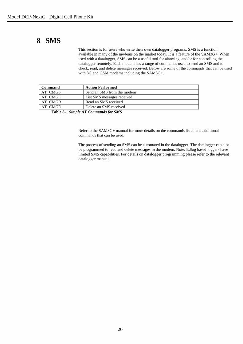
8 SMS This section is for users who write their own datalogger programs. SMS is a function
available in many of the modems on the market today. It is a feature of the SAM3G+. When
used with a datalogger, SMS can be a useful tool for alarming, and/or for controlling the
datalogger remotely. Each modem has a range of commands used to send an SMS and to
check, read, and delete messages received. Below are some of the commands that can be used
with 3G and GSM modems including the SAM3G+.
Command Action Performed
AT+CMGS Send an SMS from the modem
AT+CMGL List SMS messages received
AT+CMGR Read an SMS received
AT+CMGD Delete an SMS received
Table 8-1 Simple AT Commands for SMS
Refer to the SAM3G+ manual for more details on the commands listed and additional
commands that can be used.
The process of sending an SMS can be automated in the datalogger. The datalogger can also
be programmed to read and delete messages in the modem. Note: Edlog based loggers have
limited SMS capabilities. For details on datalogger programming please refer to the relevant
datalogger manual.
Model DCP-NextG Digital Cell Phone Kit
21
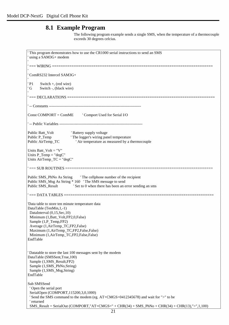
8.1 Example Program The following program example sends a single SMS, when the temperature of a thermocouple
exceeds 30 degrees celcius.
' This program demonstrates how to use the CR1000 serial instructions to send an SMS
' using a SAM3G+ modem
'
' === WIRING ==========================================================================
'
' ComRS232 Intercel SAM3G+
'
' P1 Switch +, (red wire)
' G Switch -, (black wire)
'
' === DECLARATIONS ====================================================================
' -- Constants ------------------------------------------------------------------------
Const COMPORT = ComME ' Comport Used for Serial I/O
' -- Public Variables -----------------------------------------------------------------
Public Batt_Volt ' Battery supply voltage
Public P_Temp ' The logger's wiring panel temperature
Public AirTemp_TC ' Air temperature as measured by a thermocouple
Units Batt_Volt = "V"
Units P_Temp = "degC"
Units AirTemp_TC = "degC"
' === SUB ROUTINES ====================================================================
Public SMS_PhNo As String ' The cellphone number of the recipient
Public SMS_Msg As String * 160 ' The SMS message to send
Public SMS_Result ' Set to 0 when there has been an error sending an sms
' === DATA TABLES =====================================================================
'Data table to store ten minute temperature data
DataTable (TenMin,1,-1)
DataInterval (0,15,Sec,10)
Minimum (1,Batt_Volt,FP2,0,False)
Sample (1,P_Temp,FP2)
Average (1,AirTemp_TC,FP2,False)
Maximum (1,AirTemp_TC,FP2,False,False)
Minimum (1,AirTemp_TC,FP2,False,False)
EndTable
' Datatable to store the last 100 messages sent by the modem
DataTable (SMSSent,True,100)
Sample (1,SMS_Result,FP2)
Sample (1,SMS_PhNo,String)
Sample (1,SMS_Msg,String)
EndTable
Sub SMSSend
' Open the serial port
SerialOpen (COMPORT,115200,3,0,1000)
' Send the SMS command to the modem (eg. AT+CMGS=0412345678) and wait for ">" to be
' returned
SMS_Result = SerialOut (COMPORT,"AT+CMGS=" + CHR(34) + SMS_PhNo + CHR(34) + CHR(13),">",1,100)
Model DCP-NextG Digital Cell Phone Kit
22
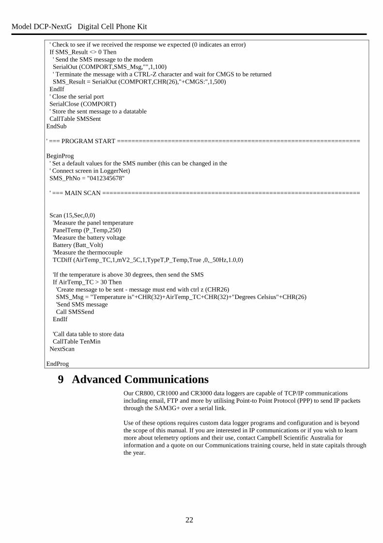
' Check to see if we received the response we expected (0 indicates an error)
If SMS_Result <> 0 Then
' Send the SMS message to the modem
SerialOut (COMPORT,SMS_Msg,"",1,100)
' Terminate the message with a CTRL-Z character and wait for CMGS to be returned
SMS_Result = SerialOut (COMPORT,CHR(26),"+CMGS:",1,500)
EndIf
' Close the serial port
SerialClose (COMPORT)
' Store the sent message to a datatable
CallTable SMSSent
EndSub
' === PROGRAM START ===================================================================
BeginProg
' Set a default values for the SMS number (this can be changed in the
' Connect screen in LoggerNet)
SMS_PhNo = "0412345678"
' === MAIN SCAN =======================================================================
Scan (15,Sec,0,0)
'Measure the panel temperature
PanelTemp (P_Temp,250)
'Measure the battery voltage
Battery (Batt_Volt)
'Measure the thermocouple
TCDiff (AirTemp_TC,1,mV2_5C,1,TypeT,P_Temp,True ,0,_50Hz,1.0,0)
'If the temperature is above 30 degrees, then send the SMS
If AirTemp_TC > 30 Then
'Create message to be sent - message must end with ctrl z (CHR26)
SMS_Msg = "Temperature is"+CHR(32)+AirTemp_TC+CHR(32)+"Degrees Celsius"+CHR(26)
'Send SMS message
Call SMSSend
EndIf
'Call data table to store data
CallTable TenMin
NextScan
EndProg
9 Advanced Communications Our CR800, CR1000 and CR3000 data loggers are capable of TCP/IP communications
including email, FTP and more by utilising Point-to Point Protocol (PPP) to send IP packets
through the SAM3G+ over a serial link.
Use of these options requires custom data logger programs and configuration and is beyond
the scope of this manual. If you are interested in IP communications or if you wish to learn
more about telemetry options and their use, contact Campbell Scientific Australia for
information and a quote on our Communications training course, held in state capitals through
the year.
Model DCP-NextG Digital Cell Phone Kit
23
10 Troubleshooting There are many steps involved in getting your phone modem ready for use and each step must be completed before the
unit can be used. Please use the following points to check that you have the correct setup.
Do you have the wiring correct? A common fault is to have the SC932A adapter around the wrong way. Please check your wiring against the figure 4.1
in section 4. The gender of these devices allows connection in reverse.
Do you have power to the unit? If you are using switched 12V please check the wiring to make sure that it is being turned on as programmed. When
properly connected, the green LED on the modem will be flashing or solid, depending on modem activity.
Do you have the antenna connected? Ensure that the antenna (and surge suppressor, if applicable) is connected to the modem.
Do you have network coverage?
This can be easily tested if you have a mobile phone on the Telstra network. If not, you can check using the modem
directly by connecting to the modem with a terminal program (See section 7.2.1) and sending AT+CSQ followed by the
Enter key. The modem will return two numbers in the form +CSQ: x,y where x is your signal strength (0-31, 31 is
best) and y is your bit error rate - you can normally disregard this second number. If your signal strength is lower than
9, you may experience disconnections and low data rates.
Do you have the modem set up to communicate with the logger at the correct baud rate? The default for the modem is to communicate at 115200 to any device. For some Campbell Scientific data loggers,
such as the Array-Based data loggers, the maximum baud rate is 9600. Please check the data logger manual for
maximum baud rate, and program the modem accordingly.
Is the SIM card inserted correctly? The SIM card should be inserted into the modem as shown in section 4.
Does the SIM card require a PIN? If it does then this needs to be disabled. A PIN is used by default, so if you did not specify it, then your SIM card most
likely has one. To disable the PIN you need to put the card into a normal digital mobile phone and select the security
menu. Exact key presses will depend on the mobile phone used but from this menu you should be able to disable the
PIN. Alternatively the following command can be used to disable the PIN: AT+CLCK=”SC”,0,”XXXX” where XXXX
is the pin number. The quotes are required.
Does the SIM card have the data service enabled?
This will be a separate number to your voice number. If you only have one phone number for the phone then it is
most likely the voice number. Check with your service provider to get the data service enabled using Bearer Code
2620 – see Section 3 This is the number that the modem must be called on. If you have difficulty getting a data
number activated on your SIM, contact Campbell Scientific.
Model DCP-NextG Digital Cell Phone Kit
24
Campbell Scientific Companies
Campbell Scientific Australia Pty. Ltd. (CSA)
PO Box 8108 Garbutt
QLD 4814
AUSTRALIA
www.campbellsci.com.au
PH: +61 7 4401 7700
Campbell Scientific Africa Pty. Ltd. (CSAf)
PO Box 2450
Somerset West 7129
SOUTH AFRICA
www.csafrica.co.za
Campbell Scientific do Brazil Ltda. (CSB)
Rua Luisa Crapsi Orsi, 15 Butantã
CEP: 005543-000 São Paulo SP
BRAZIL
www.campbellsci.com.br
Campbell Scientific Canada Corp. (CSC)
11564 - 149th Street NW
Edmonton, Alberta T5M 1W7
CANADA
www.campbellsci.ca
Campbell Scientific, Inc. (CSI)
815 West 1800 North
Logan, Utah 84321
UNITED STATES
www.campbellsci.com
Campbell Scientific Ltd. (CSL)
Campbell Park
80 Hathern Road
Shepshed, Loughborough LE12 9GX
UNITED KINGDOM
www.campbellsci.co.uk
Campbell Scientific Ltd. (France)
Miniparc du Verger - Bat. H
1, rue de Terre Neuve - Les Ulis
91967 COURTABOEUF CEDEX
FRANCE
www.campbellsci.fr
Campbell Scientific Spain, S. L.
Psg. Font 14, local 8
08013 Barcelona
SPAIN
www.campbellsci.es
Please visit www.campbellsci.com to obtain contact information for your local Campbell Scientific representative.