Embed Size (px)
Citation preview
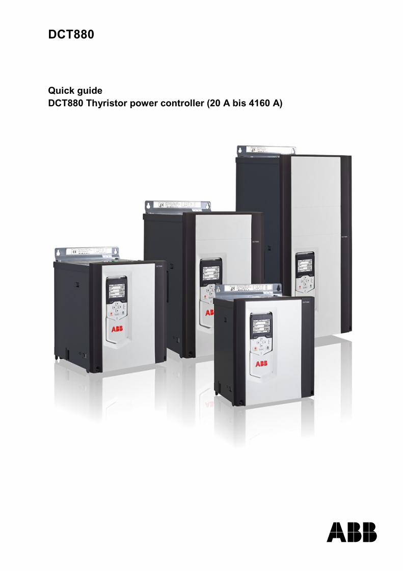
DCT880
Quick guide DCT880 Thyristor power controller (20 A bis 4160 A)

3
Safety Instructions Chapter overview This chapter contains the safety instructions you must follow when installing, operating and servicing the thyristor power controller. If ignored, physical injury or death may follow, or damage may occur to the thyristor power controller or the connected equipment. Read the safety instructions before you work on the unit.
To which products this chapter applies The information is valid for the whole range of the product DCT880.
Usage of warnings and notes There are two types of safety instructions throughout this manual: warnings and notes. Warnings caution you about conditions, which can result in serious injury or death and/or damage to the equipment, and advice on how to avoid the danger. Notes draw attention to a particular condition or fact, or give information on a subject. The warning symbols are used as follows:
Dangerous voltage warning warns of high voltage, which can cause physical injury or death and/or damage to the equipment.
General danger warning warns about conditions, other than those caused by electricity, which can result in physical injury or death and/or damage to the equipment.
Electrostatic sensitive devices warning warns of electrostatic discharge, which can damage the equipment.
Installation and maintenance work These warnings are intended for all who work on the thyristor power controller, the cables or the connected equipment. Ignoring the instructions can cause physical injury or death and/or damage to the equipment.
WARNING! 1. Only qualified electricians are allowed to install and maintain the thyristor power
controller! − Never work on the thyristor power controller, the cables or the connected equipment when
main power is applied. Always ensure by measuring with a multimeter (impedance at least 1 Mohm) that:
1. Voltage between thyristor power controller input phases U1, V1, W1 and the frame is close to 0 V.
2. Voltage between thyristor power controller output phases U2, V2, W2 and the frame is close to 0 V.
− Do not work on the control cables when power is applied to the thyristor power controller or to the external control circuits. Externally supplied control circuits may cause dangerous voltages inside the thyristor power controller even when the main power on the thyristor power controller is switched off.
− Do not make any insulation resistance or voltage withstand tests on the thyristor power controller.
− Isolate the cables to the equipment from the thyristor power controller when testing the insulation resistance or voltage withstand of the cables or the equipment.
− When reconnecting the cables to the equipment, always check that the U2, V2 and W2 cables are connected with the proper terminal.
Note: − The output phase cable terminals on the thyristor power controller are at a dangerously high
voltage when the main power is on. − Depending on the external wiring, dangerous voltages (115 V, 220 V or 230 V) may be
present on the relay outputs of the drive system (e.g. XRO1 … XRO3). − DCT880 with enclosure extension: Before working on the thyristor power controller, isolate
the whole thyristor power controller system from the supply.
Safety Instructions
3ADW000435R0101 DCT880 Quick guide e a
4
Grounding These instructions are intended for all who are responsible for the grounding of the thyristor power controller. Incorrect grounding can cause physical injury, death and/or equipment malfunction and increase electromagnetic interference.
WARNING! − Ground the thyristor power controller, the connected equipment and adjoining devices to
ensure personnel safety in all circumstances, and to reduce electromagnetic emission and pick-up.
− Make sure that grounding conductors are adequately sized and marked as required by safety regulations.
− In a multiple thyristor power controller installation, connect each thyristor power controller separately to protective earth (PE).
− Minimize EMC emission and make a 360° high frequency grounding (e.g. conductive sleeves) of screened cable entries at the cabinet lead-through plate.
Note: − Power cable shields are suitable as equipment grounding conductors only when adequately
sized to meet safety regulations. − As the normal leakage current of the thyristor power controller is higher than 3.5 mAAC or
10 mADC (stated by EN 50178, 5.2.11.1), a fixed protective earth connection is required. Printed circuit boards and fiber optic cables These instructions are intended for all who handle the circuit boards and fiber optic cables. Ignoring the following instructions can cause damage to the equipment.
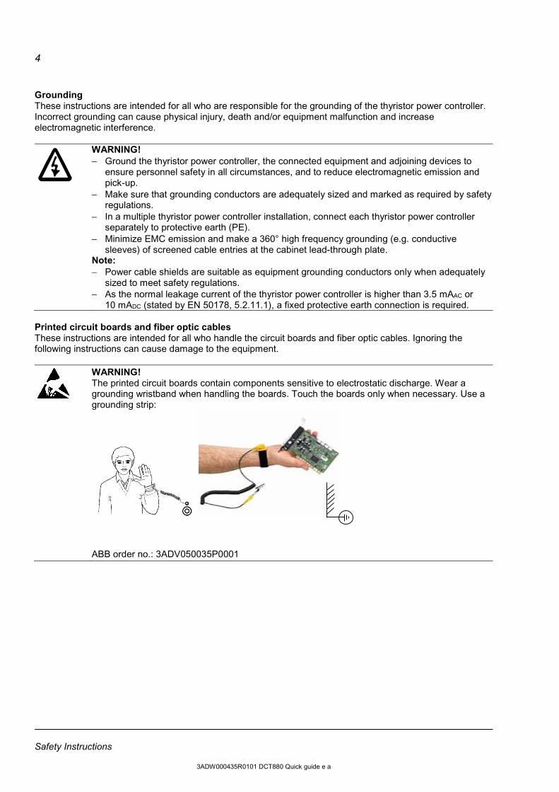
WARNING! The printed circuit boards contain components sensitive to electrostatic discharge. Wear a grounding wristband when handling the boards. Touch the boards only when necessary. Use a grounding strip:
ABB order no.: 3ADV050035P0001
Safety Instructions
3ADW000435R0101 DCT880 Quick guide e a
5
Mechanical installation These notes are intended for all who install the thyristor power controller. Handle the unit carefully to avoid damage and injury.
WARNING! − DCT880 sizes T4 and T5: The thyristor power controller is heavy. Do not lift it alone. Do not
lift the unit by the front cover. Place units T4 and T5 only on its back. − Make sure that dust from drilling does not enter the thyristor power controller when installing.
Electrically conductive dust inside the unit may cause damage or lead to malfunction. − Ensure sufficient cooling. − Do not fasten the drive by riveting or welding.
Operation These warnings are intended for all who plan the operation of the thyristor power controller or operate the thyristor power controller. Ignoring the instructions can cause physical injury or death and/or damage to the equipment.
WARNING! − Before adjusting the thyristor power controller and putting it into service, make sure that all
connected equipment is suitable for operation throughout the voltage/current range provided by the thyristor power controller.
− Do not control the connected equipment with the disconnecting device (disconnecting mains); instead, use the control panel keys and , or commands via the I/O board of the thyristor power controller.
− Mains connection You can use a disconnect switch (with fuses) to disconnect the electrical components of the thyristor power controller from the mains for installation and maintenance work. The type of disconnect switch used must be as per EN 60947-3, Class B, so as to comply with EU regulations, or a circuit-breaker type which switches off the load circuit by means of an auxiliary contact causing the breaker's main contacts to open. The mains disconnect must be locked in its "OPEN" position during any installation and maintenance work.
− EMERGENCY POWER OFF buttons must be installed at each control desk and at all other control panels requiring an emergency off function. Pressing the Stop button on the control panel of the thyristor power controller will not cause an emergency off by the thyristor power controller and it will not disconnect the thyristor power controller from any dangerous potential. To avoid unintentional operating states, or to shut the unit down in case of any imminent danger according to the standards in the safety instructions it is not sufficient to merely shut down the drive via signals Run, Enable respectively from control panel or PC tool.
− Intended use The operating instructions cannot take into consideration every possible case of configuration, operation or maintenance. Thus, they mainly give such advice only, which is required by qualified personnel for normal operation of the machines and devices in industrial installations. If in special cases the electrical machines and devices are intended for use in non-industrial installations - which may require stricter safety regulations (e.g. protection against contact by children or similar) - these additional safety measures for the installation must be provided by the customer during assembly.
Note: − When the control location is not set to Local (Local not shown in the status row of the
display), the Stop key on the control panel will not stop the thyristor power controller. To stop the thyristor power controller using the control panel, press the Loc/Rem key and then the Stop key .
Safety Instructions
3ADW000435R0101 DCT880 Quick guide e a
6
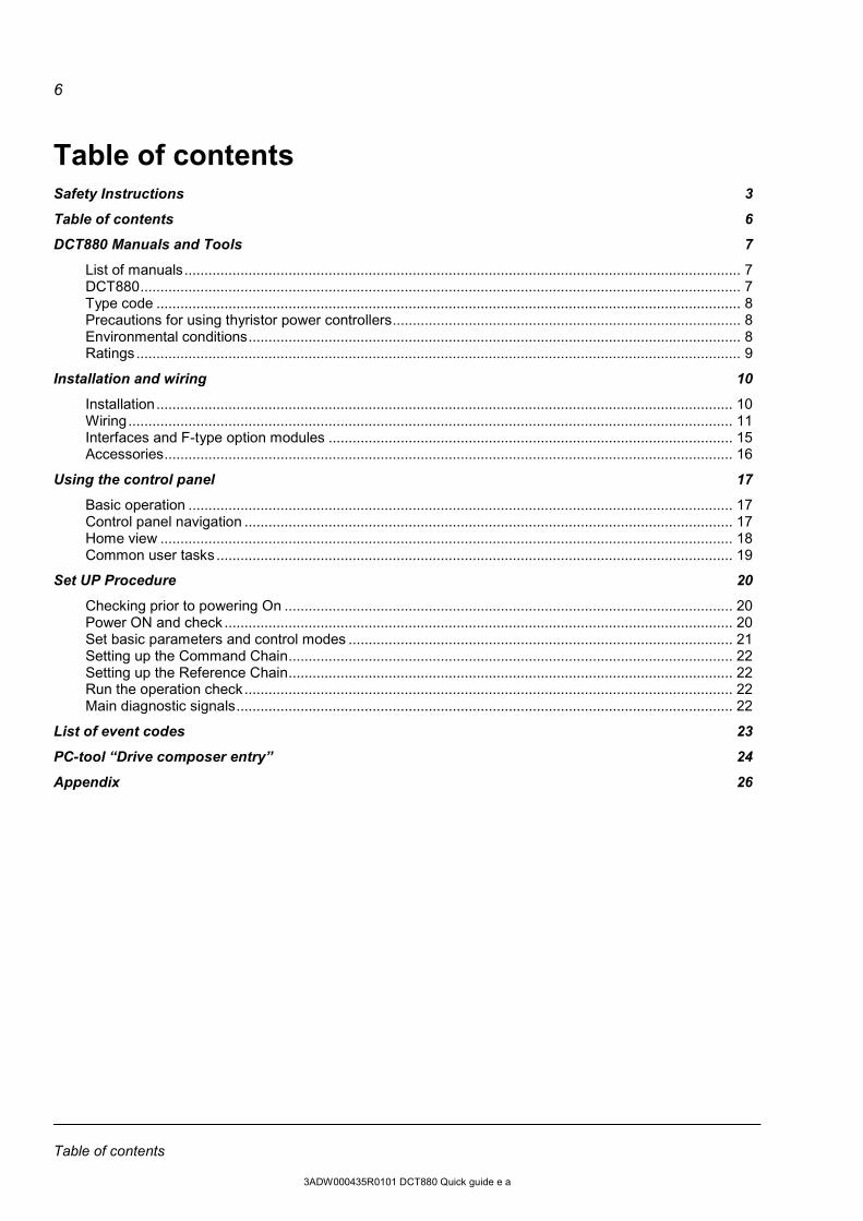
Table of contents Safety Instructions 3
Table of contents 6
DCT880 Manuals and Tools 7
List of manuals ........................................................................................................................................... 7 DCT880 ...................................................................................................................................................... 7 Type code .................................................................................................................................................. 8 Precautions for using thyristor power controllers ....................................................................................... 8 Environmental conditions ........................................................................................................................... 8 Ratings ....................................................................................................................................................... 9
Installation and wiring 10
Installation ................................................................................................................................................ 10 Wiring ....................................................................................................................................................... 11 Interfaces and F-type option modules ..................................................................................................... 15 Accessories .............................................................................................................................................. 16
Using the control panel 17
Basic operation ........................................................................................................................................ 17 Control panel navigation .......................................................................................................................... 17 Home view ............................................................................................................................................... 18 Common user tasks ................................................................................................................................. 19
Set UP Procedure 20
Checking prior to powering On ................................................................................................................ 20 Power ON and check ............................................................................................................................... 20 Set basic parameters and control modes ................................................................................................ 21 Setting up the Command Chain ............................................................................................................... 22 Setting up the Reference Chain ............................................................................................................... 22 Run the operation check .......................................................................................................................... 22 Main diagnostic signals ............................................................................................................................ 22
List of event codes 23
PC-tool “Drive composer entry” 24
Appendix 26
Table of contents
3ADW000435R0101 DCT880 Quick guide e a
7
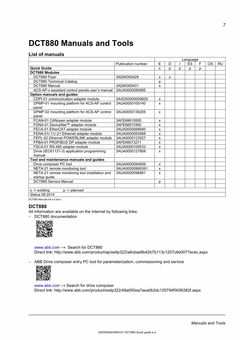
DCT880 Manuals and Tools List of manuals Language Publication number E D I ES F CN RU Quick Guide x p p p p DCT880 Modules
DCT880 Flyer 3ADW000429 x x DCT880 Technical Catalog p DCT880 Manual 3ADW000431 x ACS-AP-x assistant control panels user’s manual 3AUA0000085685
Option manuals and guides CDPI-01 communication adapter module 3AXD50000009929 x DPMP-01 mounting platform for ACS-AP control panel
3AUA0000100140 x
DPMP-02 mounting platform for ACS-AP control panel
3AUA0000136205 x
FCAN-01 CANopen adapter module 3AFE68615500 x FDNA-01 DeviceNet™ adapter module 3AFE68573360 x FECA-01 EtherCAT adapter module 3AUA0000068940 x FENA-01/-11/-21 Ethernet adapter module 3AUA0000093568 x FEPL-02 Ethernet POWERLINK adapter module 3AUA0000123527 x FPBA-01 PROFIBUS DP adapter module 3AFE68573271 x FSCA-01 RS-485 adapter module 3AUA0000109533 x Drive (IEC61131-3) application programming manual
3AUA0000127808 x
Tool and maintenance manuals and guides Drive composer PC tool 3AUA0000094606 x NETA-21 remote monitoring tool 3AUA00000969391 x NETA-21 remote monitoring tool installation and startup guide
3AUA0000096881 x
DCT880 Service Manual p x -> existing p -> planned Status 08.2014
DCT880 Manuals list e b.docx
DCT880 All information are available on the Internet by following links: − DCT880 documentation
www.abb.com → Search for DCT880 Direct link: http://www.abb.com/product/ap/seitp322/a6cbaa9b42b7b113c1257c6e0077ecec.aspx
− ABB Drive composer entry PC tool for parameterization, commissioning and service
www.abb.com → Search for drive composer Direct link: http://www.abb.com/product/seitp322/48a055ea7aea0b2dc125794f0056382f.aspx
Manuals and Tools
3ADW000435R0101 DCT880 Quick guide e a
8
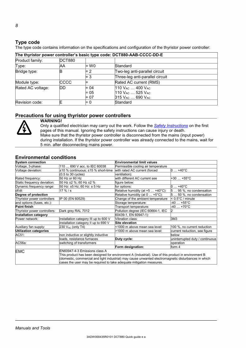
Type code The type code contains information on the specifications and configuration of the thyristor power controller:
The thyristor power controller’s basic type code: DCT880-AAB-CCCC-DD-E Product family: DCT880 Type: AA = W0 Standard Bridge type: B = 2 Two-leg anti-parallel circuit
= 3 Three-leg anti-parallel circuit Module type: CCCC = Rated AC current (RMS) Rated AC voltage: DD = 04
= 05 = 07
110 VAC … 400 VAC 110 VAC … 525 VAC 315 VAC … 690 VAC
Revision code: E = 0 Standard
Precautions for using thyristor power controllers
WARNING! Only a qualified electrician may carry out the work. Follow the Safety Instructions on the first pages of this manual. Ignoring the safety instructions can cause injury or death. Make sure that the thyristor power controller is disconnected from the mains (input power) during installation. If the thyristor power controller was already connected to the mains, wait for 5 min. after disconnecting mains power.
Environmental conditions System connection Environmental limit values Voltage, 3-phase: 110 … 690 V acc. to IEC 60038 Permissible cooling air temperature Voltage deviation: ±10 % continuous; ±15 % short-time with rated AC current (forced 0 … +40°C (0.5 to 30 cycles) ventilation): Rated frequency: 50 Hz or 60 Hz with different AC current see +30 … +55°C Static frequency deviation: 50 Hz ±2 %; 60 Hz ±2 % figure below: Dynamic frequency range: 50 Hz: ±5 Hz; 60 Hz: ± 5 Hz for options: 0 … +40°C df/dt: 17 % / s Relative humidity (at +5 … +40°C): 5 … 95 %, no condensation Degree of protection Relative humidity (at 0 … +5°C): 5 … 50 %, no condensation Thyristor power controllers IP 00 (EN 60529) Change of the ambient temperature < 0.5°C / minute and options (fuses, etc.): Storage temperature: -40 … +55°C Paint finish Transport temperature: -40 … +70°C Thyristor power controllers: Dark grey RAL 7012 Pollution degree (IEC 60664-1, IEC 2 Installation category 60439-1, EN 60947-1): Power network: installation category III up to 600 V Vibration class: 3M3 installation category II up to 690 V Site elevation Auxiliary fan supply: 230 VAC (only T4) <1000 m above mean sea level: 100 %, no current reduction Utilization categories >1000 m above mean sea level: current reduction, see figure AC51: non inductive or slightly inductive below loads, resistance furnaces Duty cycle: uninterrupted duty / continuous AC56a: switching of transformers operation Form designation: form 4 EMC EN60947-4-3 Emissions class A
This product has been designed for environment A (Industrial). Use of this product in environment B (domestic, commercial and light industrial) may cause unwanted electromagnetic disturbances in which cases the user may be required to take adequate mitigation measures.
Manuals and Tools
3ADW000435R0101 DCT880 Quick guide e a
9
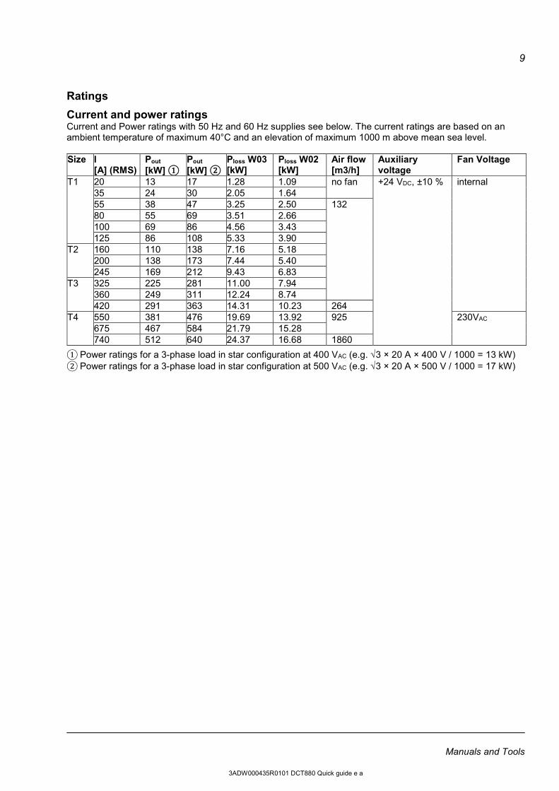
Ratings
Current and power ratings Current and Power ratings with 50 Hz and 60 Hz supplies see below. The current ratings are based on an ambient temperature of maximum 40°C and an elevation of maximum 1000 m above mean sea level. Size I
[A] (RMS) Pout [kW] ①
Pout [kW] ②
Ploss W03 [kW]
Ploss W02 [kW]
Air flow [m3/h]
Auxiliary voltage
Fan Voltage
T1 20 13 17 1.28 1.09 no fan +24 VDC, ±10 % internal 35 24 30 2.05 1.64 55 38 47 3.25 2.50 132 80 55 69 3.51 2.66 100 69 86 4.56 3.43 125 86 108 5.33 3.90
T2 160 110 138 7.16 5.18 200 138 173 7.44 5.40 245 169 212 9.43 6.83
T3 325 225 281 11.00 7.94 360 249 311 12.24 8.74 420 291 363 14.31 10.23 264
T4 550 381 476 19.69 13.92 925 230VAC 675 467 584 21.79 15.28 740 512 640 24.37 16.68 1860
① Power ratings for a 3-phase load in star configuration at 400 VAC (e.g. √3 × 20 A × 400 V / 1000 = 13 kW) ② Power ratings for a 3-phase load in star configuration at 500 VAC (e.g. √3 × 20 A × 500 V / 1000 = 17 kW)
Manuals and Tools
3ADW000435R0101 DCT880 Quick guide e a
10
Installation and wiring Installation
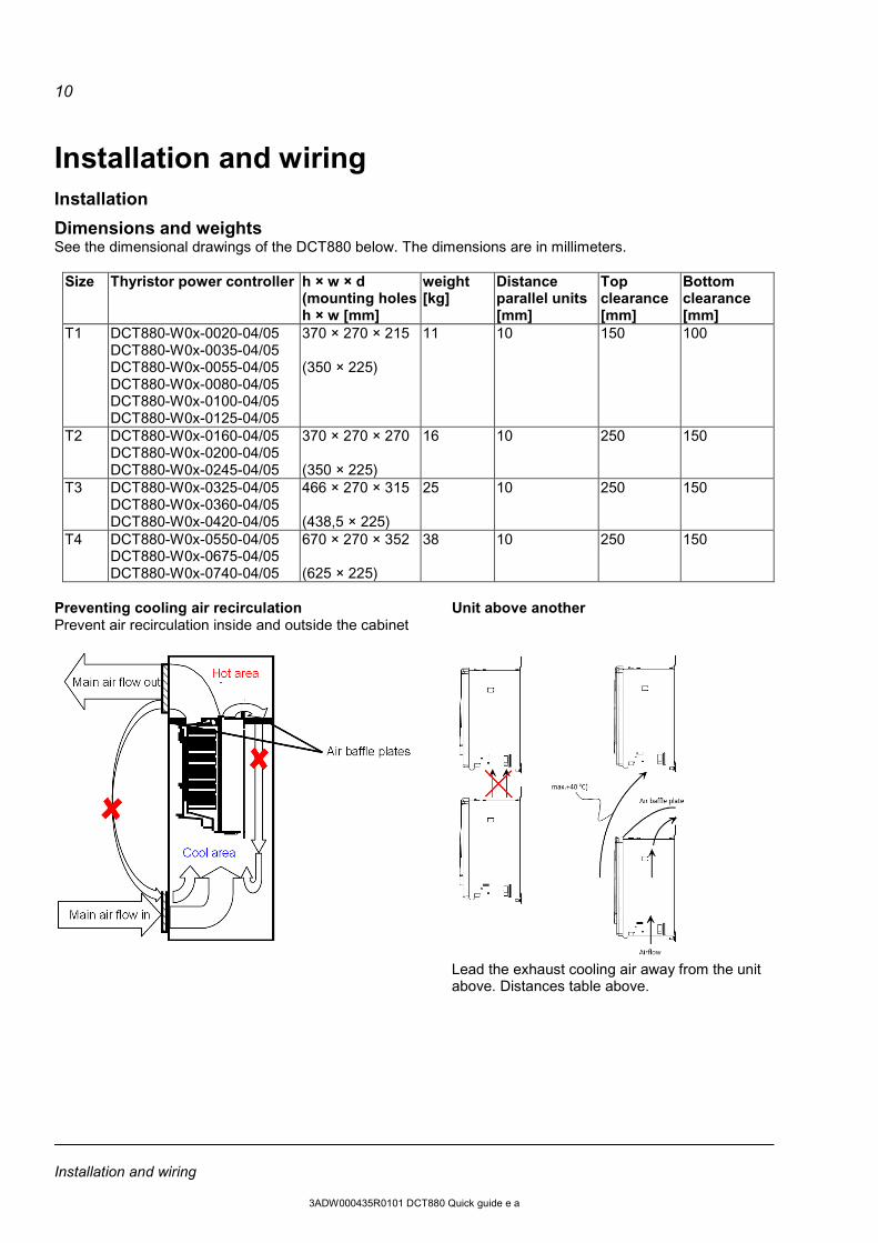
Dimensions and weights See the dimensional drawings of the DCT880 below. The dimensions are in millimeters.
Size Thyristor power controller h × w × d (mounting holes h × w [mm]
weight [kg]
Distance parallel units [mm]
Top clearance [mm]
Bottom clearance [mm]
T1 DCT880-W0x-0020-04/05 DCT880-W0x-0035-04/05 DCT880-W0x-0055-04/05 DCT880-W0x-0080-04/05 DCT880-W0x-0100-04/05 DCT880-W0x-0125-04/05
370 × 270 × 215 (350 × 225)
11 10 150 100
T2 DCT880-W0x-0160-04/05 DCT880-W0x-0200-04/05 DCT880-W0x-0245-04/05
370 × 270 × 270 (350 × 225)
16 10 250 150
T3 DCT880-W0x-0325-04/05 DCT880-W0x-0360-04/05 DCT880-W0x-0420-04/05
466 × 270 × 315 (438,5 × 225)
25 10 250 150
T4 DCT880-W0x-0550-04/05 DCT880-W0x-0675-04/05 DCT880-W0x-0740-04/05
670 × 270 × 352 (625 × 225)
38 10 250 150
Preventing cooling air recirculation Unit above another Prevent air recirculation inside and outside the cabinet
Lead the exhaust cooling air away from the unit
above. Distances table above.
Installation and wiring
3ADW000435R0101 DCT880 Quick guide e a
11
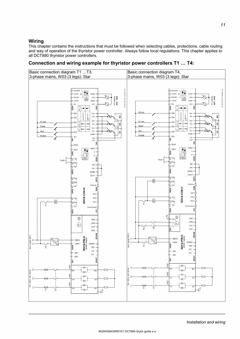
Wiring This chapter contains the instructions that must be followed when selecting cables, protections, cable routing and way of operation of the thyristor power controller. Always follow local regulations. This chapter applies to all DCT880 thyristor power controllers.
Connection and wiring example for thyristor power controllers T1 … T4: Basic connection diagram T1 …T3, 3-phase mains, W03 (3 legs): Star
Basic connection diagram T4, 3-phase mains, W03 (3 legs): Star
Installation and wiring
3ADW000435R0101 DCT880 Quick guide e a
12
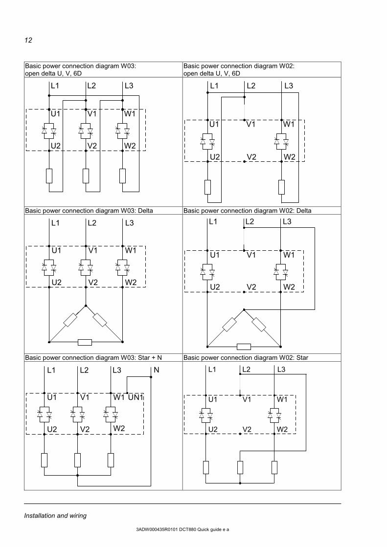
Basic power connection diagram W03: open delta U, V, 6D
Basic power connection diagram W02: open delta U, V, 6D
W2V2U2
U1 W1V1
L1 L2 L3
W2V2U2
U1 W1V1
L1 L2 L3
Basic power connection diagram W03: Delta Basic power connection diagram W02: Delta
U1
W2V2U2
W1V1
L1 L2 L3
U1
W2V2U2
W1V1
L1 L2 L3
Basic power connection diagram W03: Star + N Basic power connection diagram W02: Star
N
U1 W1V1
W2V2U2
UN1
L1 L2 L3
U1
W2V2U2
W1V1
L1 L2 L3
Installation and wiring
3ADW000435R0101 DCT880 Quick guide e a
13
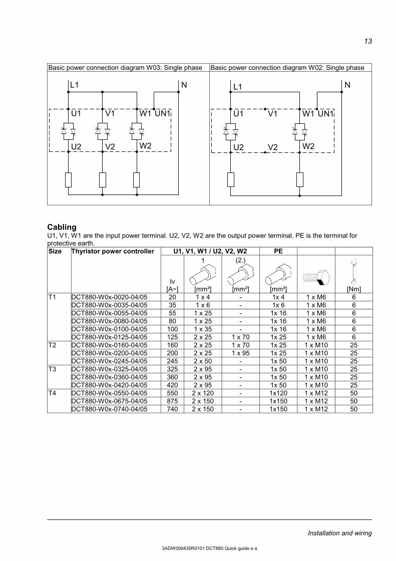
Basic power connection diagram W03: Single phase Basic power connection diagram W02: Single phase
L1 N
U1 W1V1
W2V2U2
UN1
N
U1 W1V1
W2V2U2
UN1
L1
Cabling U1, V1, W1 are the input power terminal. U2, V2, W2 are the output power terminal. PE is the terminal for protective earth. Size Thyristor power controller U1, V1, W1 / U2, V2, W2 PE
Iv
[A~]
1
[mm²]
(2.)
[mm²]
[mm²]
[Nm]
T1 DCT880-W0x-0020-04/05 20 1 x 4 - 1x 4 1 x M6 6 DCT880-W0x-0035-04/05 35 1 x 6 - 1x 6 1 x M6 6 DCT880-W0x-0055-04/05 55 1 x 25 - 1x 16 1 x M6 6 DCT880-W0x-0080-04/05 80 1 x 25 - 1x 16 1 x M6 6 DCT880-W0x-0100-04/05 100 1 x 35 - 1x 16 1 x M6 6 DCT880-W0x-0125-04/05 125 2 x 25 1 x 70 1x 25 1 x M6 6
T2 DCT880-W0x-0160-04/05 160 2 x 25 1 x 70 1x 25 1 x M10 25 DCT880-W0x-0200-04/05 200 2 x 25 1 x 95 1x 25 1 x M10 25 DCT880-W0x-0245-04/05 245 2 x 50 - 1x 50 1 x M10 25
T3 DCT880-W0x-0325-04/05 325 2 x 95 - 1x 50 1 x M10 25 DCT880-W0x-0360-04/05 360 2 x 95 - 1x 50 1 x M10 25 DCT880-W0x-0420-04/05 420 2 x 95 - 1x 50 1 x M10 25
T4 DCT880-W0x-0550-04/05 550 2 x 120 - 1x120 1 x M12 50 DCT880-W0x-0675-04/05 875 2 x 150 - 1x150 1 x M12 50 DCT880-W0x-0740-04/05 740 2 x 150 - 1x150 1 x M12 50
Installation and wiring
3ADW000435R0101 DCT880 Quick guide e a
14
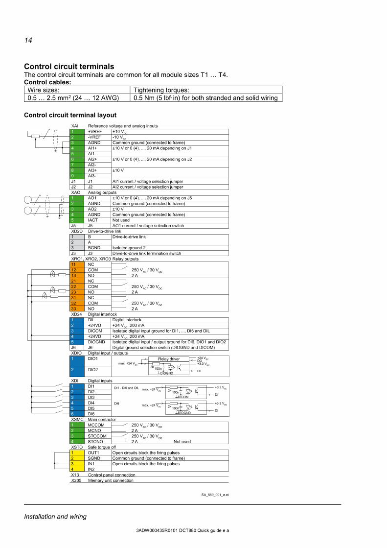
Control circuit terminals The control circuit terminals are common for all module sizes T1 … T4. Control cables:
Wire sizes: Tightening torques: 0.5 … 2.5 mm2 (24 … 12 AWG) 0.5 Nm (5 lbf·in) for both stranded and solid wiring
Control circuit terminal layout
Installation and wiring
3ADW000435R0101 DCT880 Quick guide e a
15
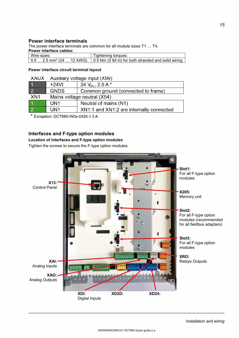
Power interface terminals The power interface terminals are common for all module sizes T1 … T4. Power interface cables:
Wire sizes: Tightening torques: 0.5 … 2.5 mm2 (24 … 12 AWG) 0.5 Nm (5 lbf·in) for both stranded and solid wiring
Power interface circuit terminal layout
Interfaces and F-type option modules Location of interfaces and F-type option modules Tighten the screws to secure the F-type option modules.
X13: Control Panel
XAI: Analog Inputs
XAO:
Analog Outputs
Slot1: For all F-type option modules X205: Memory unit Slot2: For all F-type option modules (recommended for all fieldbus adapters) Slot3: For all F-type option modules XRO: Relays Outputs
XDI: XD2D: XD24: Digital Inputs
Installation and wiring
3ADW000435R0101 DCT880 Quick guide e a
16
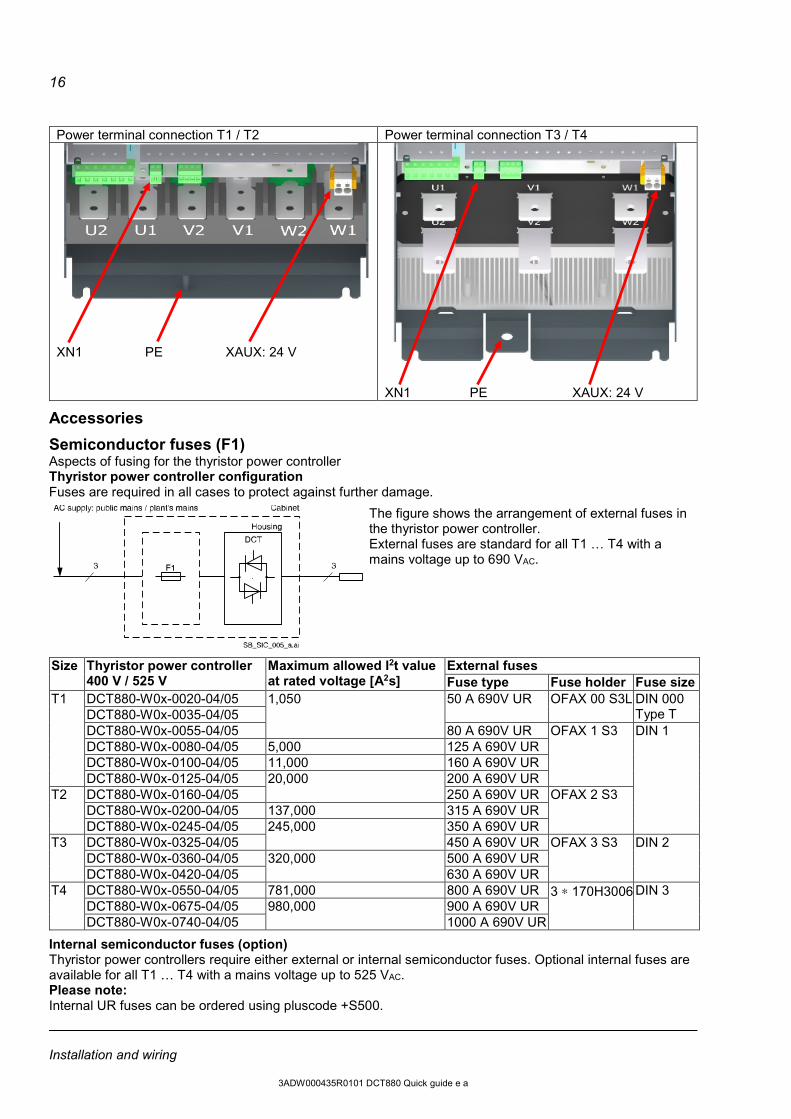
Power terminal connection T1 / T2 Power terminal connection T3 / T4
XN1 PE XAUX: 24 V
XN1 PE XAUX: 24 V
Accessories
Semiconductor fuses (F1) Aspects of fusing for the thyristor power controller Thyristor power controller configuration Fuses are required in all cases to protect against further damage.
The figure shows the arrangement of external fuses in the thyristor power controller. External fuses are standard for all T1 … T4 with a mains voltage up to 690 VAC.
Size Thyristor power controller 400 V / 525 V
Maximum allowed I2t value at rated voltage [A2s]
External fuses Fuse type Fuse holder Fuse size
T1 DCT880-W0x-0020-04/05 1,050 50 A 690V UR OFAX 00 S3L DIN 000 Type T DCT880-W0x-0035-04/05
DCT880-W0x-0055-04/05 80 A 690V UR OFAX 1 S3 DIN 1 DCT880-W0x-0080-04/05 5,000 125 A 690V UR DCT880-W0x-0100-04/05 11,000 160 A 690V UR DCT880-W0x-0125-04/05 20,000 200 A 690V UR
T2 DCT880-W0x-0160-04/05 250 A 690V UR OFAX 2 S3 DCT880-W0x-0200-04/05 137,000 315 A 690V UR DCT880-W0x-0245-04/05 245,000 350 A 690V UR
T3 DCT880-W0x-0325-04/05 450 A 690V UR OFAX 3 S3 DIN 2 DCT880-W0x-0360-04/05 320,000 500 A 690V UR DCT880-W0x-0420-04/05 630 A 690V UR
T4 DCT880-W0x-0550-04/05 781,000 800 A 690V UR 3 ∗ 170H3006 DIN 3 DCT880-W0x-0675-04/05 980,000 900 A 690V UR DCT880-W0x-0740-04/05 1000 A 690V UR
Internal semiconductor fuses (option) Thyristor power controllers require either external or internal semiconductor fuses. Optional internal fuses are available for all T1 … T4 with a mains voltage up to 525 VAC. Please note: Internal UR fuses can be ordered using pluscode +S500. Installation and wiring
3ADW000435R0101 DCT880 Quick guide e a
17
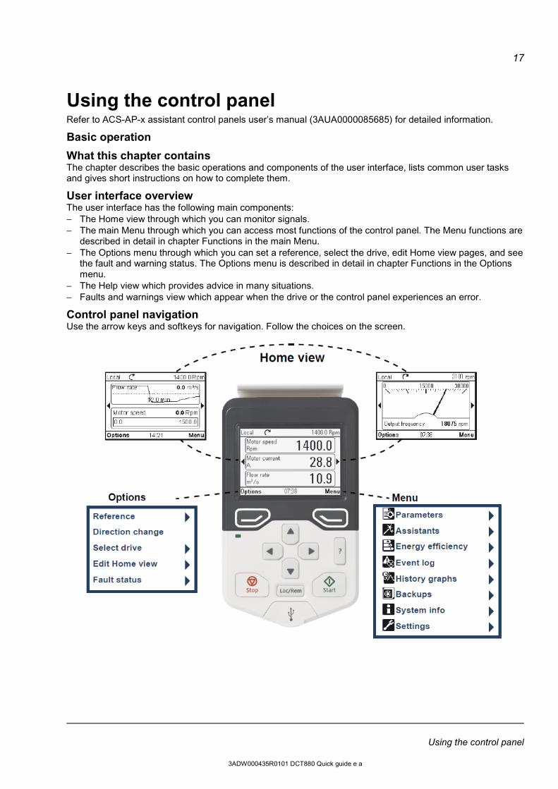
Using the control panel Refer to ACS-AP-x assistant control panels user’s manual (3AUA0000085685) for detailed information.
Basic operation
What this chapter contains The chapter describes the basic operations and components of the user interface, lists common user tasks and gives short instructions on how to complete them.
User interface overview The user interface has the following main components: − The Home view through which you can monitor signals. − The main Menu through which you can access most functions of the control panel. The Menu functions are
described in detail in chapter Functions in the main Menu. − The Options menu through which you can set a reference, select the drive, edit Home view pages, and see
the fault and warning status. The Options menu is described in detail in chapter Functions in the Options menu.
− The Help view which provides advice in many situations. − Faults and warnings view which appear when the drive or the control panel experiences an error.
Control panel navigation Use the arrow keys and softkeys for navigation. Follow the choices on the screen.
Using the control panel
3ADW000435R0101 DCT880 Quick guide e a
18
Navigation memory The Assistant control panel has a navigation memory that allows you to backtrack your steps through the user interface with the arrow keys and . The path you have last accessed remains in the memory for 10 minutes. − The left arrow key ( ) moves you backwards in the menu structure. If you press repeatedly, you return
back to the Home view. − The right arrow key ( ) moves you forward in the menu structure. If you press repeatedly, you move
forward along the path in the menu structure you had previously accessed.
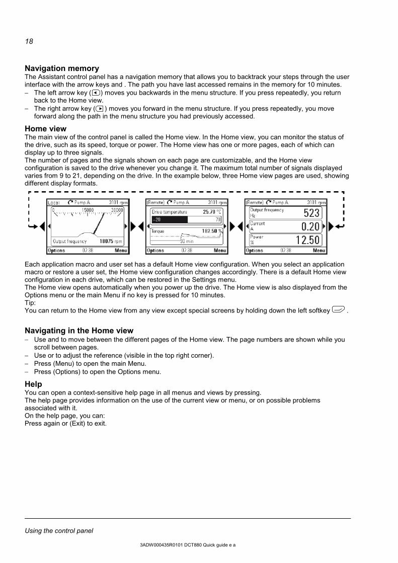
Home view The main view of the control panel is called the Home view. In the Home view, you can monitor the status of the drive, such as its speed, torque or power. The Home view has one or more pages, each of which can display up to three signals. The number of pages and the signals shown on each page are customizable, and the Home view configuration is saved to the drive whenever you change it. The maximum total number of signals displayed varies from 9 to 21, depending on the drive. In the example below, three Home view pages are used, showing different display formats.
Each application macro and user set has a default Home view configuration. When you select an application macro or restore a user set, the Home view configuration changes accordingly. There is a default Home view configuration in each drive, which can be restored in the Settings menu. The Home view opens automatically when you power up the drive. The Home view is also displayed from the Options menu or the main Menu if no key is pressed for 10 minutes. Tip: You can return to the Home view from any view except special screens by holding down the left softkey .
Navigating in the Home view − Use and to move between the different pages of the Home view. The page numbers are shown while you
scroll between pages. − Use or to adjust the reference (visible in the top right corner). − Press (Menu) to open the main Menu. − Press (Options) to open the Options menu.
Help You can open a context-sensitive help page in all menus and views by pressing. The help page provides information on the use of the current view or menu, or on possible problems associated with it. On the help page, you can: Press again or (Exit) to exit.
Using the control panel
3ADW000435R0101 DCT880 Quick guide e a
19
Common user tasks This following tables list common user tasks and describe how to complete them. See Functions in the main Menu and Functions in the Options menu for detailed descriptions of functions in the menus.
Basic operation of the drive Task Actions Start and stop the drive. In local control, press to start the drive and to stop the drive. Set the reference (for example, speed) in the Home view. In local control, go to Options > Reference.
Set the reference with the arrow keys. Switch between local and remote control. Press REM/LOC
Parameters Task Actions Choose parameters displayed on the Favorites list. Go to Menu > Parameters > Favorites > Edit. View/edit parameters. Go to Menu > Parameters to view parameters.
Move by arrow keys and save using left soft key. View parameters that differ from Application Macro defaults. Go to Menu > Parameters > Modified.
System information and help Task Actions How to get help. Press to open the context-sensitive help. View control panel version. Go to Menu > System info > Control panel. View drive information. Go to Menu > System info > Drive.
Faults and warnings Task Actions Hide/view an active fault. Faults are automatically displayed. If you hide a fault by pressing
(Hide), it automatically reappears after 60 seconds of no key presses. You can also view the fault through Options > Fault status.
Open help page on a fault. Press to view the help page. Reset an active fault. Press (Reset) to reset an active fault. View tripping faults. Go to Menu > Event log > Primary faults. Hide/view an active warning. Warnings are automatically displayed. If you hide a warning by
pressing (Hide), it automatically reappears if the warning is still active after 60 seconds of no key presses.
Open help page on a warning. Press (How to fix) or to view the help page. Reset an active warning. Warnings disappear automatically once the condition that has
triggered it goes away. View past warnings and faults. Go to Menu > Event log > Other events.
Basic settings and assistants Task Actions Change language. Go to Menu > Settings > Language. Change time and date, and related settings. Go to Menu > Settings > Date & time. Launch an assistant. Go to Menu > Assistants and select an assistant to launch.
Backups Task Actions Create a backup. Creates an backup of firmware parameters to the panel. Restore a backup. Restores a backup to the firmware parameters of DCT880. It is
mandatory to set the unit in local mode before.
Using the control panel
3ADW000435R0101 DCT880 Quick guide e a
20
Set UP Procedure Follow the procedure below for setting up the thyristor power controller
Checking prior to powering On Check the following before powering on the thyristor power controller (1) Check the wiring to the input terminals U1, V1 and W1 and output terminals U2, V2 and W2. Also check
that the grounding wires are connected to the grounding terminals (PE).
WARNING! Be sure to connect the grounding wires of the power controller to the ground electrodes. Otherwise, an electric shock could occur.
(2) Check the wiring to the aux. voltage supply. (3) Check the wiring to neutral point connection for single phase or 3ph + neutral configurations connected to
XN1 : 1 (4) Check the control circuit terminals and main circuit terminals for short circuit or ground faults. (5) Check for loose terminals, connectors and screws. (6) Make sure that all switches of devices connected to the power controller are turned OFF.
Power on the power controller with any of those switches being ON may cause unexpected behavior at load side.
Power ON and check
WARNING! Be sure to mount the front cover before turning the power ON. Do not remove the cover when the power controller is ON. Do not operate switches with wet hands. Otherwise, an electric shock could occur.
Turn the aux. power ON and check the following points. The following is a case when no parameter data is changed from factory defaults. (1) Check that the assistant control panel displays no fault and set date and time (2) Check that the used analog and digital inputs work properly
Check signals 12.11, 12.21 and 12.31 for analog inputs Check signals 10.1 for digital inputs Set the inputs from voltage to current if needed
Turn on the input power and check the following points. (1) Check following parameters a. In case of three phase system supply Voltage between input phases
signals 1.07, 1.08, 1.09 b. In case of single phase system supply Voltage between phase and neutral
signals 1.01, 1.02, 1.03
Set UP Procedure
3ADW000435R0101 DCT880 Quick guide e a
21
Set basic parameters and control modes Please look up your configuration in following tables and set up accordingly
Basic settings for supply and load configuration Parameters Parameter
name Parameters setting
99.01 Supply Voltage Actual supply voltage (U1, V1, W1 / U1, N) 99.02 Load current Rated load current 99.03 Load Voltage Rated voltage across the load 99.04 Supply
Configuration 0 3ph UVW For W03 1 3ph UW eco For W02 2 3 x 1ph + N For W03 and W02 connected to single phase 6 2ph Scot For W02
For detailed description see Chapter Parameters 99.05 Load
Configuration 0 3ph Star (3S) 1 3ph Star +N (4S) 2 3ph Delta (3D) 3 3ph open Delta UV (6D) 4 3ph open Delta UW (6D) 5 3ph Transformer (3D/3S) 6 3ph Transformer UV (6D) 7 3ph Transformer UW (6D) 8 Scot Transfomer 9 3 x 1ph loads 10 3 x 1ph transformer loads
For detailed description see Chapter Parameters 99.10 Leg 1 Control
Mode 2 Full Wave Fix Cycle 3 Full Wave Variable Cycle 4 Half Wave
5 U α Open loop control 6 U² α Open loop control 7 I α Control 8 I² α Control 9 U α Control 10 U² α Control 11 P α Control 12 Leg 1 External Ref 23.65
99.25 Leg 2 Control Mode
As 99.10 for separately controlled loads 13 Follow Leg 1, for 3ph common controlled loads
99.40 Leg 3 Control Mode
As 99.10 for separately controlled loads 13 Follow Leg 1, for 3ph common controlled loads
Additional settings for Phase Angle Control Parameters Parameter name Parameters setting 99.16 / 99.31 / 99.46
Leg 1 / 2 / 3 Phase Angle Soft Start Ramp
Set to desired soft start period, to prevent current overshoot at start
Set UP Procedure
3ADW000435R0101 DCT880 Quick guide e a
22
Additional settings for Full Wave Fix Cycle Parameters Parameter name Parameters setting 99.11 / 99.26 / 99.41
Leg 1 / 2 / 3 Cycle Time
Set to desired fixed cycle time
99.12 / 99.27 / 99.42
Leg 1 Start Mode
1 First Angle Starts always using first angle 99.13 / 28 / 43 2 Soft Start Starts using 99.14 / 29 / 44 one time
3 Soft Start / Soft Down
Start using 99.14 / 29 / 44 Stops using 99.15 / 30 / 45
4 Soft Start / first Angle
First Start using 99.14 / 29 / 44 after using 99.13 / 28 / 43
For detailed description see Chapter Parameters 99.13 / 99.28 / 99.43
Leg 1 / 2 / 3 First Angle
First angle to magnetize the transformer. Recommended setting range 80° ~ 90°
99.14 / 99.29 / 99.44
Leg 1/ 2 / 3 Burst Soft Start Ramp
Set to desired soft start period
99.15 / 99.30 / 99.45
Leg 1 / 2 / 3 Burst Soft Down Ramp
Set to desired soft down period
Additional settings for Full Wave Fix Cycle and Full Wave Variable Cycle Parameters Parameter name Parameters setting 23.23 / 25.23 / 27.23
Leg 1 / 2 / 3 Minimum Cycle variable Burst
Set the minimum cycle for variable burst
Setting up the Command Chain By factory default the ON/OFF Control is set to following: LEG 1 Parameter LEG 2 Parameter LEG 3 Parameter Enable DI1 19.01 DI1 19.03 DI1 19.05 RUN DI2 19.02 DI2 19.04 DI2 19.06 Reset DI3 19.15 See Leg 1 Command Location Selector
DI5
19.10
DI5
19.11
DI5
19.12
See also DI Status in parameter 10.01. If you need differently please check settings of given parameters.
Setting up the Reference Chain By factory default the reference chain is set to following: LEG 1 Parameter LEG 2 Parameter LEG 3 Parameter Main Reference AI1
scaled 22.15 AI2
scaled 24.15 AI3
scaled 26.15
See also AI Status in parameters 12.12, 12.22 and 12.32. If you need differently please check settings of given parameter and also description of Reference Groups 22 / 24 / 26.
Run the operation check
Main diagnostic signals Parameter Parameter name Description 1.26 / 1.27 / 1.28 Mains Voltage Leg 1 / 2 / 3 relative Relative measured mains voltage 1.30 / 1.31 / 1.32 Leg 1 / 2 / 3 Current RMS actual RMS current per leg 1.40 / 1.41 / 1.42 Leg 1 / 2 / 3 Alpha actual Actual firing angle 1.60 / 1.61 / 1.62 Leg 1 / 2 / 3 Voltage RMS relative actual Actual relative output voltage 6.05 / 6.06 / 6.07 Leg 1 / 2 / 3 Status word Actual status words
Set UP Procedure
3ADW000435R0101 DCT880 Quick guide e a
23
List of event codes If the power controller detects an event, check whether any warning or fault code appears on the assistant control panel. As listed below, some warnings and fault codes are followed by sub codes that denote the detailed error causes. For codes not followed by sub codes, "--" is written in the table below. Events valid for all legs are only listed at leg 1. For the alarm sub code checking procedure please see chapter “Using the control panel” Table Abnormal states detectable (Fault and Warning Objects) Leg1 Fault code
Leg1 Warning code
Leg2 Fault code
Leg2 Warning code
Leg3 Fault code
Leg3 Warning code
Error cause Auto Reset object
Sub code
Detailed error cause
3101 2101 3201 2201 3301 2301 Overcurrent X 3102 2102 3202 2202 3302 2302 Overvoltage X 3103 2103 3203 2203 3303 2303 Thyristor short circuit 3104 2104 3204 2204 3304 2304 Thyristor open 3105 2105 3205 2205 3305 2305 Under voltage X 3154 2154 3354 2254 3354 2354 Unit overload X 5211 1201 External Event 1 X -- 5212 1202 External Event 2 X -- 5213 1203 External Event 3 X -- 5214 1204 External Event 4 X -- 5215 1205 External Event 5 X -- 1132 Parameter setting conflict 3151 2151 3251 2251 3351 2351 Load loss X 3152 2152 3252 2252 3352 2352 Partial load loss X 3153 2153 3253 2252 3353 2353 Partial load short circuit X 3155 2155 3255 2255 3355 2355 Load overload X 3157 2157 3257 2257 3357 2357 Load aging 3158 2158 3258 2258 3358 3358 Load current imbalance X
List of event codes
3ADW000435R0101 DCT880 Quick guide e a
24
PC-tool “Drive composer entry” Drive composer entry is a free of charge startup and maintenance PC tool for ABB's common architecture industrial devices series such as ACS880, DCT880 etc. The key functions of Drive composer entry are the following: − Connect point-to-point to one DCT880 using Assistant control panel's USB port − Show the actual status of the connected DCT880 − View, edit on line and search the DCT880 parameters − Show modified DCT880 parameters (Not at default) − Print parameters − Save parameters from DCT880 to PC and download parameters from PC to DCT880 − Monitor drive signals graphically and numerically (Limited functionality) − Local Control of a DCT880 − Use of workspace and customized parameter windows Download the software from the internet: www.abb.com → Search for Drive composer
Unzip the Drive_composer_entry.zip file
Start the installation program Setup.exe of Drive composer entry and follow the instruction carefully
Connect the panel to your PC
Install the second part of drivers manually as follows
In the Start menu of your computer, enter Device manager in the search field and click Device Manager
Click Browse my computer for driver software to search the driver software
Click Browse to locate the drivers and click Next.
In the Windows Security window, click Install to install the device software
After installation is complete, click Close.
PC-tool
3ADW000435R0101 DCT880 Quick guide e a
25
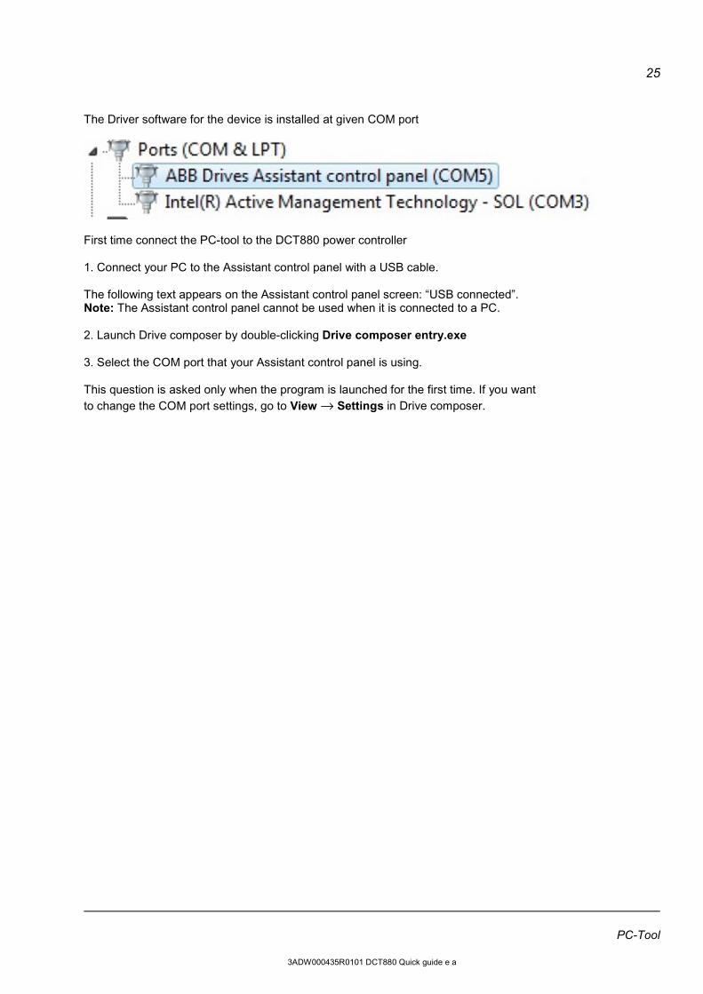
The Driver software for the device is installed at given COM port
First time connect the PC-tool to the DCT880 power controller 1. Connect your PC to the Assistant control panel with a USB cable. The following text appears on the Assistant control panel screen: “USB connected”. Note: The Assistant control panel cannot be used when it is connected to a PC. 2. Launch Drive composer by double-clicking Drive composer entry.exe 3. Select the COM port that your Assistant control panel is using. This question is asked only when the program is launched for the first time. If you want to change the COM port settings, go to View → Settings in Drive composer.
PC-Tool
3ADW000435R0101 DCT880 Quick guide e a

26
Appendix
Appendix
3ADW000435R0101 DCT880 Quick guide e a

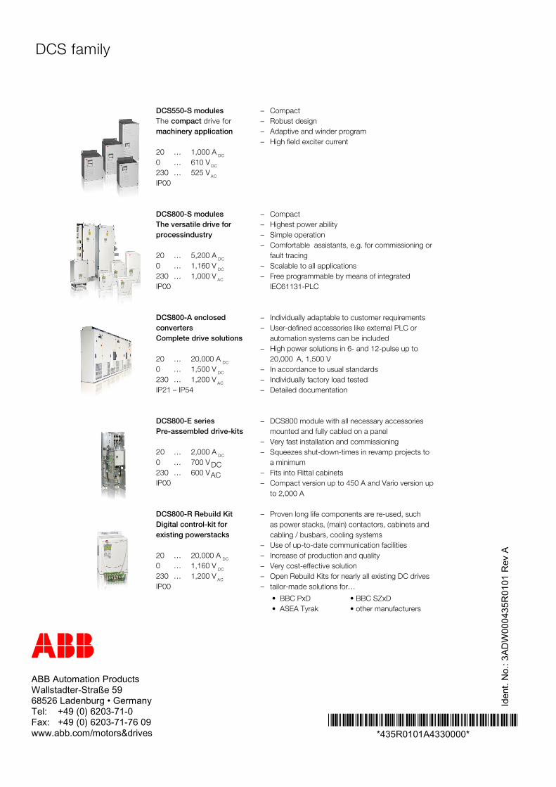
ABB Automation Products Wallstadter-Straße 59 68526 Ladenburg • Germany Tel: +49 (0) 6203-71-0 Fax: +49 (0) 6203-71-76 09 www.abb.com/motors&drives
*435R0101A4330000* *435R0101A4330000*
Iden
t. N
o.: 3
AD
W00
0435
R01
01 R
ev A
– Compact– Robust design– Adaptive and winder program– High field exciter current
– Compact– Highest power ability– Simple operation– Comfortable assistants, e.g. for commissioning or
fault tracing– Scalable to all applications– Free programmable by means of integrated
IEC61131-PLC
– Individually adaptable to customer requirements– User-defined accessories like external PLC or
automation systems can be included– High power solutions in 6- and 12-pulse up to
20,000 A, 1,500 V– In accordance to usual standards– Individually factory load tested– Detailed documentation
– DCS800 module with all necessary accessoriesmounted and fully cabled on a panel
– Very fast installation and commissioning– Squeezes shut-down-times in revamp projects to
a minimum– Fits into Rittal cabinets– Compact version up to 450 A and Vario version up
to 2,000 A
– Proven long life components are re-used, suchas power stacks, (main) contactors, cabinets andcabling / busbars, cooling systems
– Use of up-to-date communication facilities– Increase of production and quality– Very cost-effective solution– Open Rebuild Kits for nearly all existing DC drives– tailor-made solutions for…
DCS550-S modulesThe compact drive formachinery application
20 … 1,000 A DC
0 … 610 VDC
230 … 525 VAC
IP00
DCS800-S modulesThe versatile drive forprocessindustry
20 … 5,200 ADC
0 … 1,160 VDC
230 … 1,000 VAC
IP00
DCS800-A enclosedconvertersComplete drive solutions
20 … 20,000 ADC
0 … 1,500 VDC
230 … 1,200 VAC
IP21 – IP54
DCS800-E seriesPre-assembled drive-kits
20 … 2,000 ADC
0 … 700 V DC230 … 600 VACIP00
DCS800-R Rebuild KitDigital control-kit forexisting powerstacks
20 … 20,000 ADC
0 … 1,160 VDC
230 … 1,200 VAC
IP00
DCS family
• BBC PxD • BBC SZxD• ASEA Tyrak • other manufacturers