Embed Size (px)
Citation preview
low voltage
DD-SERIES-CAT-V2DEC 2017
CataloguePage 1 of 33
DD Frame - Series Circuit Breakers
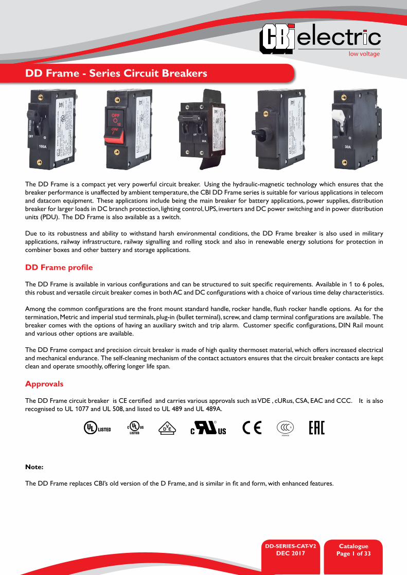
The DD Frame is a compact yet very powerful circuit breaker. Using the hydraulic-magnetic technology which ensures that the breaker performance is unaffected by ambient temperature, the CBI DD Frame series is suitable for various applications in telecom and datacom equipment. These applications include being the main breaker for battery applications, power supplies, distribution breaker for larger loads in DC branch protection, lighting control, UPS, inverters and DC power switching and in power distribution units (PDU). The DD Frame is also available as a switch. Due to its robustness and ability to withstand harsh environmental conditions, the DD Frame breaker is also used in military applications, railway infrastructure, railway signalling and rolling stock and also in renewable energy solutions for protection in combiner boxes and other battery and storage applications.
DD Frame profile
The DD Frame is available in various configurations and can be structured to suit specific requirements. Available in 1 to 6 poles, this robust and versatile circuit breaker comes in both AC and DC configurations with a choice of various time delay characteristics.
Among the common configurations are the front mount standard handle, rocker handle, flush rocker handle options. As for the termination, Metric and imperial stud terminals, plug-in (bullet terminal), screw, and clamp terminal configurations are available. The breaker comes with the options of having an auxiliary switch and trip alarm. Customer specific configurations, DIN Rail mount and various other options are available.
The DD Frame compact and precision circuit breaker is made of high quality thermoset material, which offers increased electrical and mechanical endurance. The self-cleaning mechanism of the contact actuators ensures that the circuit breaker contacts are kept clean and operate smoothly, offering longer life span.
Approvals
The DD Frame circuit breaker is CE certified and carries various approvals such as VDE , cURus, CSA, EAC and CCC. It is also recognised to UL 1077 and UL 508, and listed to UL 489 and UL 489A.
S
A005438
Note:
The DD Frame replaces CBI’s old version of the D Frame, and is similar in fit and form, with enhanced features.
DD-SERIES-CAT-V2DEC 2017
CataloguePage 2 of 33
low voltage
DD Frame - Series Circuit Breakers
• AC and DC circuit breaker• Hydraulic-magnetic technology• 100% rating capability independent of ambient temperature • Up to six poles• VDE, EAC and CCC approved, CE certified• UL compliant (listed / recognised)• Ratings 0.1 to 100 A AC and 400 A DC
(specific certifications)• Precision tripping characteristics• Wide range of circuits, mountings, terminations and time
delays• Two colour handle indication (two tone flush rocker)• Optional mid-trip indication (standard handle)• Optional auxiliary switch and trip alarm
Features Applications• AC and DC branch circuit installations• Power conditioning• Telecom DC power distribution• Alternative energy equipment• UPS equipment• Lighting control• Mobile power generation equipment• Battery protection
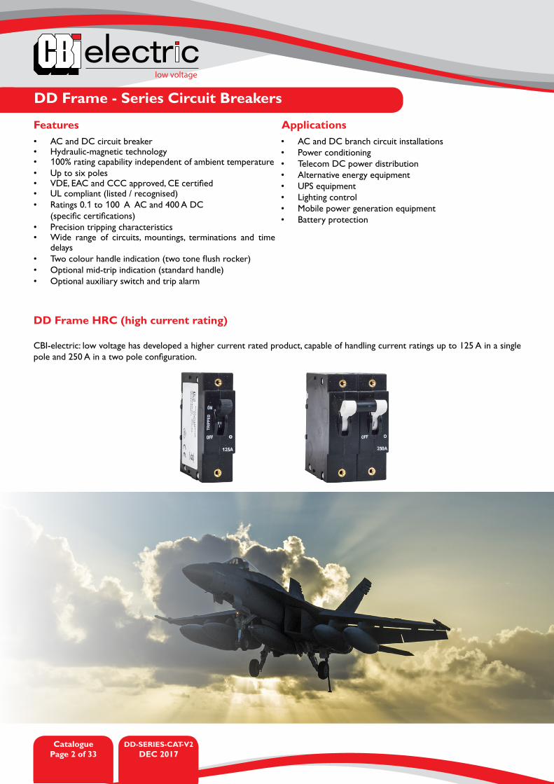
DD Frame HRC (high current rating)
CBI-electric: low voltage has developed a higher current rated product, capable of handling current ratings up to 125 A in a single pole and 250 A in a two pole configuration.

low voltage
DD-SERIES-CAT-V2DEC 2017
CataloguePage 3 of 33
DD Frame - Series Circuit Breakers
Technical Data
Product Type DD FrameOperating Temperature Range -40 °C to +85 °C
Endurance 10000 operations - 1500 electrical at rated current and voltage (IEC 60934)6000 electrical operations (UL 1077)
Dielectric Strength 1000 - 2000 V, 50 Hz for one minute after testing (IEC 60934)Weight 100 g per pole (unpacked)Humidity 35 to 85% relative
Altitude Certification tests done at altitude ≈ 2000 metres. Will operate at higher altitudes.
Shock 100 G to MIL-STD-202G, test method 213B, test condition 1Vibration 10 G to MIL-STD-202G test method 204D, test condition AFlammability I2 - No ignition at 850 °C with an oxygen index of ≥ 32Toxicity F1 - Smoke index of ≤ 20 which determines the fume class
Pollution Degree PD2 - Normally only non-conductive pollution occurs. Temporary conductivity caused by condensation is to be expected.
Product Type Circuit Breaker Circuit Breaker Circuit Breaker
Approvals UL 489, CSA IEC / EN 60947-2,VDE, CE, CCC
UL 489A, IEC / EN 60947-2, VDE, CE
Number of Poles 1, 2, 3 1, 2 1, 2 - 5 (parallel)
Maximum Voltages 120 V AC, 120 / 240 V AC, 240 V AC, 80 V DC
240 V AC, 80 V DC 80 V DC
Current Ratings 0.1 - 80 A AC, 0.1 - 100 A DC 0.1 - 50 A AC, 0.1 - 100 A DC 20 - 40 AInterrupting Capacity 5 kA (240 V AC), 10 kA (DC) 10 kA (120 V AC) 10 kA (DC)HIC 10 kA up to 20 A
Product Type Circuit Breaker Circuit Breaker Switch
Approvals IEC / EN 60934, VDE, CE UL 1077, CSA, cURus UL 508, IEC / EN 60947-3, VDE, CE
Number of Poles 1 - 4 1 - 4 1, 2Maximum Voltages 240 / 415 V AC, 80 V DC 277 / 480 V AC, 80 V DC 120 / 240 V AC, 240 V AC
Current Ratings 0.1 - 100 A (1 p), 0.1 - 70 A (2 - 4 p)
0.1 - 100 A (1 p), 0.1 - 70 A (2 - 4 p) 15 - 50 A
Interrupting Capacity 3 kA (AC), 5 kA (DC) 2 kA (AC), 5 kA (DC) 0.6 kA (for 1 s)
DD-SERIES-CAT-V2DEC 2017
CataloguePage 4 of 33
low voltage
DD Frame - Series Circuit Breakers
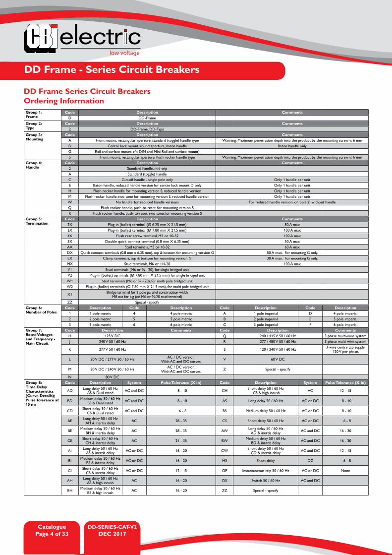
DD Frame Series Circuit BreakersOrdering InformationGroup 1: Frame
Code Description CommentsD DD-Frame
Group 2: Type
Code Description Comments2 DD-Frame, DD-Type
Group 3: Mounting
Code Description CommentsA Front mount, rectangular aperture, standard (toggle) handle type Warning: Maximum penetration depth into the product by the mounting screw is 6 mmD Centre lock mount, round aperture, baton handle Baton handle onlyG Rail and surface mount, (fit DIN and Mini Rail and surface mount)S Front mount, rectangular aperture, flush rocker handle type Warning: Maximum penetration depth into the product by the mounting screw is 6 mm
Group 4: Handle
Code Description Comments2 Standard handle, mid-tripA Standard (toggle) handleC Cut-off handle - single pole only Only 1 handle per unitE Baton handle, reduced handle version for centre lock mount D only Only 1 handle per unitH Flush rocker handle for mounting version S, reduced handle version Only 1 handle per unitM Flush rocker handle, two tone for mounting version S, reduced handle version Only 1 handle per unitW No handle, for reduced handle versions For reduced handle version, on pole(s) without handleQ Flush rocker handle, push-to-reset, for mounting version SR Flush rocker handle, push-to-reset, two tone, for mounting version S
Group 5: Termination
Code Description Comments2X Plug-in (bullet) terminal (Ø 6.25 mm X 21.5 mm) 50 A max3X Plug-in (bullet) terminal (Ø 7.80 mm X 21.5 mm) 100 A max4X Flush rear screw terminal, M5 or 10-32 100 A max5X Double quick connect terminal (0.8 mm X 6.35 mm) 50 A maxAX Stud terminals, M5 or 10-32 60 A maxDX Quick connect terminals (0.8 mm x 6.35 mm), top & bottom for mounting version G 50 A max. For mounting G only.LX Clamp terminals, top & bottom for mounting version G 30 A max. For mounting G only.MX Stud terminals, M6 or 1/4-20 100 A maxV1 Stud terminals (M6 or ¼ - 20), for single bridged unitV2 Plug-in (bullet) terminals (Ø 7.80 mm X 21.5 mm) for single bridged unitW1 Stud terminals (M6 or ¼ - 20), for multi pole bridged unitW2 Plug-in (bullet) terminals (Ø 7.80 mm X 21.5 mm), for multi pole bridged unit
X1 Bridge terminal for 2 pole parallel construction width M8 nut for lug (on M6 or ¼-20 stud terminal)
ZZ Special - specifyGroup 6: Number of Poles
Code Description Code Description Code Description Code Description1 1 pole metric 4 4 pole metric A 1 pole imperial D 4 pole imperial2 2 pole metric 5 5 pole metric B 2 pole imperial E 5 pole imperial3 3 pole metric 6 6 pole metric C 3 pole imperial F 6 pole imperial
Group 7: Rated Voltagesand Frequency - Main Circuit
Code Description Comments Code Description CommentsH 125 V DC Q 240 / 415 V 50 / 60 Hz 3 phase multi-wire systemJ 240 V 50 / 60 Hz R 277 / 480 V 50 / 60 Hz 3 phase multi-wire system
K 277 V 50 / 60 Hz S 120 / 240 V 50 / 60 Hz 3 wire centre tap supply. 120 V per phase.
L 80 V DC / 277 V 50 / 60 Hz AC / DC version. With AC and DC curves. V 60 V DC
M 80 V DC / 240 V 50 / 60 Hz AC / DC version. With AC and DC curves. Z Special - specify
N 80 V DCGroup 8: Time Delay Characteristics (Curve Details); Pulse Tolerance at 10 ms
Code Description System Pulse Tolerance (X In) Code Description System Pulse Tolerance (X In)
AD Long delay 50 / 60 HzAS & Dual rated AC and DC 8 - 10 CH Short delay 50 / 60 Hz
CS & high inrush AC 12 - 15
BD Medium delay 50 / 60 Hz BS & Dual rated AC and DC 8 - 10 AS Long delay 50 / 60 Hz AC or DC 8 - 10
CD Short delay 50 / 60 HzCS & Dual rated AC and DC 6 - 8 BS Medium delay 50 / 60 Hz AC or DC 8 - 10
AE Long delay 50 / 60 HzAH & inertia delay AC 28 - 35 CS Short delay 50 / 60 Hz AC or DC 6 - 8
BE Medium delay 50 / 60 Hz BH & inertia delay AC 28 - 35 AW Long delay 50 / 60 Hz
AD & inertia delay AC and DC 16 - 20
CE Short delay 50 / 60 HzCH & inertia delay AC 21 - 35 BW Medium delay 50 / 60 Hz
BD & inertia delay AC and DC 16 - 20
AI Long delay 50 / 60 HzAS & inertia delay AC or DC 16 - 20 CW Short delay 50 / 60 Hz
CD & inertia delay AC and DC 12 - 15
BI Medium delay 50 / 60 Hz BS & inertia delay AC or DC 16 - 20 H3 Short delay DC 6 - 8
CI Short delay 50 / 60 HzCS & inertia delay AC or DC 12 - 15 OP Instantaneous trip 50 / 60 Hz AC or DC None
AH Long delay 50 / 60 HzAS & high inrush AC 16 - 20 OX Switch 50 / 60 Hz AC and DC
BH Medium delay 50 / 60 Hz BS & high inrush AC 16 - 20 ZZ Special - specify

low voltage
DD-SERIES-CAT-V2DEC 2017
CataloguePage 5 of 33
DD Frame - Series Circuit Breakers
DD Frame Series Circuit BreakersOrdering Information
Group 10: Circuit Configuration (Circuit Breaker’s Internal Construction)
Code Description CommentsAX SwitchBX Series trip (circuit breaker, current coil in series)CX Relay trip current sensing, centre terminal construction, 4 terminal Total load 100 A maxDX Relay trip voltage sensing, centre terminal construction, 4 terminal See Group 12 for voltage optionsEX Shunt trip current sensing, 3rd terminal close to load side Total load 100 A maxFX Shunt trip voltage sensing, 3rd terminal close to load side See Group 12 for voltage options
GX Dual control shunt trip construction, 3rd terminal close to load side Curves AH, BH, CH, AE, BE, CE not possible. See Group 12 for voltage options (Voltage coil normally at line voltage).
HX Dual control relay trip construction (4 terminal) Curves AH, BH, CH, AE, BE, CE not possible. See Group 12 for voltage options.JX Switch with auxiliary switchKX Series trip, with auxiliary switchLX Series trip, mid-trip handle, with trip alarm Trip alarm requires mid-trip handleMX Series trip, trip alarm (latch type - reversed function)
H1 Dual control relay trip construction, fly leads for relay trip coil, with auxiliary switch
Fly leads (wire terminals) for relay trip coil (Group 13). Curves AH, BH, CH, AE, BE, CE not possible.
ZZ Special - specifyGroup 11: Auxiliary and Alarm Switches
Code Description CommentsX Not applicableA Gold tips, equally spaced terminals, 2.75 mm, (0.108”) 0.1 A MaxB Silver tips, equally spaced terminals, 2.75 mm, (0.108”) 10 A MaxC Silver tips, offset terminals, 4.75 mm (0.187”), 10 A MaxM Parallel bridge housing - for all parallel bridged polesZ Special - specify
Group 12:Voltage and Current Ratings for Dual Control, Shunt and Relay Trip Construction
Code Description Code Description Code Description Code DescriptionXX Not applicable A3 65 V AC 50 / 60 Hz B0 12 V DC B3 80 V DC
A1 12 V AC 50 / 60 Hz A4 110 - 125 V AC 50 / 60 Hz B1 24 V DC ZZ Special - specify
A2 24 V AC 50 / 60 Hz A5 220 - 240 V AC 50 / 60 Hz B2 48 V DC
Group 13: Terminal Options for Dual Control, Shunt and Relay Coils
Code Description CommentsX Not applicable
B Screw terminal, M5 or 10 - 32 50 A max
C Quick connect terminals (0.8 mm X 6.35 mm)
D Flying leads (wire terminals) 15 A max
E Stud terminal, M5 or 10 - 32 60 A max
Group 14: Voltage forRocker Handle
Code Description Comments
X Not applicable
Group 15: Terminal for Illuminated Rocker
Code Description Comments
X Not applicable
Group 16: Handle Colour
Code Description Comments
X No handle
B Black handle, white marking
G Green handle, white marking
W White handle, black marking
R Red handle, white marking
Y Yellow handle, black marking
Group 17: Marking
Code Description CommentsX No handle (n/a)
D I – O and ON - OFF For products requiring VDE & UL approvals
H I – O and ON - OFF and ampere rating
1 Push-to-reset and ampere rating Group 3 option S only. Group 4 options Q or R only. Flush rocker or two tone rocker handle.
Group 18: Mounting Orientation for Marking
Code Description Code Description CommentsX No handle (n/a) H Horizontal (line at the left) If the breaker needs to be reverse fed, the
printing will be upside down and codes 1 or 2 should be selected.
1 Vertical (reverse mounting, line at the bottom) V Vertical (standard mounting, line at the top)
2 Horizontal (line at the right)
Group 19: Front Plate Marking and Test Button
Code Description Comments Code Description Comments
1 Standard marking, with test button, standard handle
Test button for mechanical trip A Standard marking, standard handle I – O and ON - OFF and ampere rating
2 No marking, with test button, rocker handle
Test button for mechanical trip B No marking, rocker handle
Group 9: Rated Current (Main Circuit) Examples only - Specific A Rating Possible
Code Description CommentsXXXX No current, for voltage trip poles
Specific A rating possible from 0.1 – 400 A050M 50 mA100 1 A1000 10 AK400 400 A
DD-SERIES-CAT-V2DEC 2017
CataloguePage 6 of 33
low voltage
DD Frame - Series Circuit Breakers
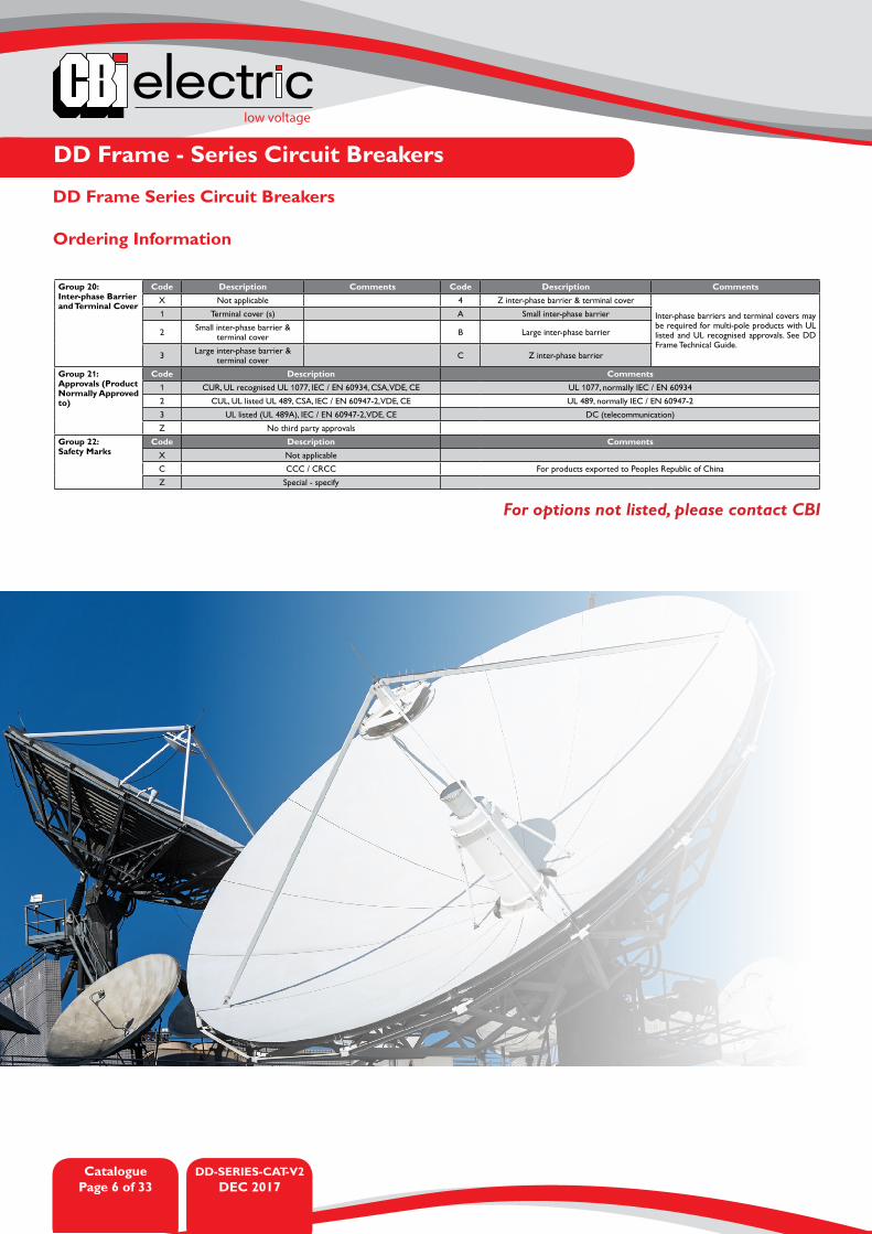
Group 20: Inter-phase Barrier and Terminal Cover
Code Description Comments Code Description CommentsX Not applicable 4 Z inter-phase barrier & terminal cover
Inter-phase barriers and terminal covers may be required for multi-pole products with UL listed and UL recognised approvals. See DD Frame Technical Guide.
1 Terminal cover (s) A Small inter-phase barrier
2 Small inter-phase barrier & terminal cover B Large inter-phase barrier
3 Large inter-phase barrier & terminal cover C Z inter-phase barrier
Group 21: Approvals (Product Normally Approved to)
Code Description Comments1 CUR, UL recognised UL 1077, IEC / EN 60934, CSA, VDE, CE UL 1077, normally IEC / EN 60934
2 CUL, UL listed UL 489, CSA, IEC / EN 60947-2, VDE, CE UL 489, normally IEC / EN 60947-2
3 UL listed (UL 489A), IEC / EN 60947-2, VDE, CE DC (telecommunication)
Z No third party approvals
Group 22: Safety Marks
Code Description CommentsX Not applicable
C CCC / CRCC For products exported to Peoples Republic of China
Z Special - specify
DD Frame Series Circuit Breakers
Ordering Information
For options not listed, please contact CBI

low voltage
DD-SERIES-CAT-V2DEC 2017
CataloguePage 7 of 33
DD Frame - Series Circuit Breakers
DD Frame 80 V DC - UL 489
DD Frame 80 V DC - IEC / EN 60947-2, VDEU
L 48
9
Poles 1 Pole 2 Pole
80 V DC X X
Standard Handle 0.1 - 100 A; 10 kA 0.1 - 100 A; 10 kA
Reduced Handle 0.1 - 100 A; 10 kA 0.1 - 50 A; 5 kA
Rocker Handle Flush 0.1 - 100 A; 10 kA 0.1 - 80 A, 10 kA
Front Mount X X
Rail Mount
Centre Lock
Stud M5 ≤ 60 A ≤ 60 A
Stud M6 ≤ 100 A ≤ 100 A
Plug-in (Bullet) 6.25 mm ≤ 50 A ≤ 50 A
Plug-in (Bullet) 7.8 mm ≤ 100 A ≤ 100 A
Screw Terminal
Double Qk connect ≤ 50 A ≤ 50 A
Flying Leads (Dual Voltage) X X
Series Trip X X
Series Mid Trip X X
Dual Control X X
Dual Control Shunt Trip 30 VA coil
Dual Control Relay Trip 30 VA coil
Shunt Trip 3 VA coil X X
Relay Trip 3 VA coil X X
Time Delay AS longest tested. AH & AI up to 30 A also tested. Faster curves can be specified
IEC
/ E
N
6094
7-2
VD
E
Poles 4 Pole Parallel 5 Pole Parallel
80 V DC X X
Standard Handle 300 A 400 A
Reduced Handle
Rocker Handle Flush
Front Mount
Rail Mount
Centre Lock
Stud M5
Stud M6 X X
Plug-in (Bullet) 6.25 mm X X
Plug-in (Bullet) 7.8 mm X X
Screw Terminal
Double Qk Connect
Flying Leads
Series Trip X X
Series Mid Trip X X
Dual Control X X
Dual Control Shunt Trip 30 VA coil X X
Dual Control Relay Trip 30 VA coil X X
Shunt Trip 3 VA coil
Relay Trip 3 VA coil X X
Time Delay AS, BS, CS, H3, AI, BI, CI, AH, BH, CH, AE, BE, CE, AD, BD, C, AW, BW, CW
Inter-phase Barrier Small
Inter-phase Barrier Large
Inter-phase Barrier Z type
Auxiliary Switch Silver X X
Auxiliary Switch Gold X X

DD-SERIES-CAT-V2DEC 2017
CataloguePage 8 of 33
low voltage
DD Frame - Series Circuit Breakers
DD Frame 80 V DC - UL 1077, CSA
DD Frame 80 V DC - UL 489A
UL
489A
Poles 1 Pole 2 Pole 2 Pole Parallel 3 Pole Parallel 4 Pole Parallel 5 Pole Parallel
80 V DC X X X X X X
Standard Handle 110 - 200 A; 10 kA 160 - 250 A; 10 kA 300 A; 10 kA 400 A; 10 kA
Reduced Handle 110 - 200 A; 10 kA 160 - 250 A; 10 kA 300 A; 10 kA 400 A; 10 kA
Rocker Handle Flush 110 - 200 A; 10 kA 160 - 250 A; 10 kA 300 A; 10 kA 400 A; 10 kA
Front Mount X X X X
Rail Mount 0.1 - 30 A; 5 A 0.1 - 30 A; 5 A
Centre Lock
Stud M5
Stud M6 X X X X
Plug-in (Bullet) 6.25 mm X X X X X X
Plug-in (Bullet) 7.8 mm X X X X X X
Screw Terminal
Double Qk Connect
Flying Leads
Series Trip X X X X X X
Series Mid Trip X X X X X X
Dual Control X X X X
Dual Control Shunt Trip 30 VA coil
Dual Control Relay Trip 30 VA coil
Shunt Trip 3 VA coil X X X X
Relay Trip 3 VA coil X X X X
Time Delay AS, BS, CS, AI, BI, CI, AD, BD, CD, AW, BW, CW, OP
AS, BS, CS, OP
Inter-phase Barrier Small X
Inter-phase Barrier Large X
Inter-phase Barrier Z type X
Auxiliary Switch Silver X X
Auxiliary Switch Gold X X
cUR
us U
L 10
77 C
SA
Poles 1 Pole 2 Pole
80 V DC X
Standard Handle 0.1 - 100 A; 5 kA 0.1 - 80 A; 5 kA
Reduced Handle 0.1 - 100 A; 5 kA 0.1 - 80 A; 5 kA
Rocker Handle Flush 0.1 - 100 A; 5 kA 0.1 - 80 A; 5 kA
Front Mount X X
Rail Mount
Centre Lock
Stud M5 ≤ 60 A ≤ 60 A
Stud M6 ≤ 100 A ≤ 100 A
Plug-in (Bullet) 6.25 mm ≤ 50 A ≤ 50 A
Plug-in (Bullet) 7.8 mm ≤ 100 A ≤ 100 A
Screw Terminal
Double Qk Connect ≤ 50 A ≤ 50 A
Flying Leads X X
Series Trip X X
Series Mid Trip X X
Dual Control X X
Dual Control Shunt Trip 30 VA coil
Dual Control Relay Trip 30 VA coil
Shunt Trip 3 VA coil X X
Relay Trip 3 VA coil X X
Time Delay AS, BS, CS, H3, AI, BI, CI, AD, BD, CD, AW, BW, CW, OP
low voltage
DD-SERIES-CAT-V2DEC 2017
CataloguePage 9 of 33
DD Frame - Series Circuit Breakers
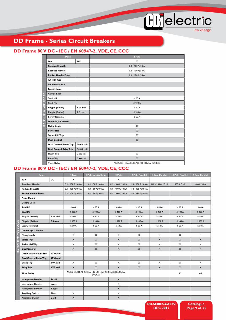
DD Frame 80 V DC - IEC / EN 60947-2, VDE, CE, CCC
DD Frame 80 V DC - IEC / EN 60947-2, VDE, CE, CCC
IEC
/ E
N 6
0934
V
DE
CC
C C
E
Poles 1 Pole
80 V DC X
Standard Handle 0.1 - 100 A; 5 kA
Reduced Handle 0.1 - 100 A; 5 kA
Rocker Handle Flush 0.1 - 100 A; 5 kA
kA with fuse
kA without fuse
Front Mount
Centre Lock
Stud M5 ≤ 60 A
Stud M6 ≤ 100 A
Plug-in (Bullet) 6.25 mm ≤ 50 A
Plug-in (Bullet) 7.8 mm ≤ 100 A
Screw Terminal ≤ 50 A
Double Qk Connect
Flying Leads X
Series Trip X
Series Mid Trip X
Dual Control X
Dual Control Shunt Trip 30 VA coil
Dual Control Relay Trip 30 VA coil
Shunt Trip 3 VA coil X
Relay Trip 3 VA coil X
Time Delay AS,BS, CS, H3, AI, BI, CI, AD, BD, CD, AW, BW, CW.
IEC
/ E
N 6
0934
VD
E C
CC
CE
Poles 1 Pole 1 Pole Inertia Delay 2 Pole 2 Pole Parallel 3 Pole Parallel 4 Pole Parallel 5 Pole Parallel
80 V DC X X
Standard Handle 0.1 - 100 A; 10 kA 0.1 - 50 A; 10 kA 0.1 - 100 A; 10 kA 110 - 180 A; 10 kA 160 - 250 A; 10 kA 300 A; 5 kA 400 A; 5 kA
Reduced Handle 0.1 - 100 A; 10 kA 0.1 - 50 A; 10 kA 0.1 - 100 A; 10 kA 110 - 180 A; 10 kA
Rocker Handle Flush 0.1 - 100 A; 10 kA 0.1 - 50 A; 10 kA 0.1 - 100 A; 10 kA 110 - 180 A; 10 kA
Front Mount
Centre Lock
Stud M5 ≤ 60 A ≤ 60 A ≤ 60 A ≤ 60 A ≤ 60 A ≤ 60 A ≤ 60 A
Stud M6 ≤ 100 A ≤ 100 A ≤ 100 A ≤ 100 A ≤ 100 A ≤ 100 A ≤ 100 A
Plug-in (Bullet) 6.25 mm ≤ 50 A ≤ 50 A ≤ 50 A ≤ 50 A ≤ 50 A ≤ 50 A ≤ 50 A
Plug-in (Bullet) 7.8 mm ≤ 100 A ≤ 100 A ≤ 100 A ≤ 100 A ≤ 100 A ≤ 100 A ≤ 100 A
Screw Terminal ≤ 50 A ≤ 50 A ≤ 50 A ≤ 50 A ≤ 50 A ≤ 50 A ≤ 50 A
Double Qk Connect
Flying Leads X X X X X X X
Series Trip X X X X X X X
Series Mid Trip X X X X X X X
Dual Control X X X X X X X
Dual Control Shunt Trip 30 VA coil
Dual Control Relay Trip 30 VA coil
Shunt Trip 3 VA coil X X X X X X X
Relay Trip 3 VA coil X X X X X X X
Time Delay AS, BS, CS, H3, AI, BI, CI, AH, BH, CH, AE, BE, CE, AD, BD, C, AW, BW, CW
AS AS
Inter-phase Barrier Small X
Inter-phase Barrier Large X
Inter-phase Barrier Z type X
Auxiliary Switch Silver X X
Auxiliary Switch Gold X X

DD-SERIES-CAT-V2DEC 2017
CataloguePage 10 of 33
low voltage
DD Frame - Series Circuit Breakers
DD Frame 80 V AC - IEC / EN 60947-2, VDE, CCC
DD Frame 80 V DC - CCC
IEC
/ E
N 6
0947
-2, V
DE
,CC
C
Poles 1 Pole 1+N 2 Pole 2 Pole inertia delay 2 Pole Parallel 3 Pole Parallel
80 V AC X X X
Standard Handle 0.1 - 100 A; 5 kA 0.1 - 50 A; 5 kA 0.1 - 50 A; 5 kA 0.1 - 40 A; 5 kA 110 - 180 A 160 - 250 A
Reduced Handle 0.1 - 100 A; 5 kA 0.1 - 50 A; 5 kA 0.1 - 50 A; 5 kA 0.1 - 40 A; 5 kA
Rocker Handle Flush 0.1 - 100 A; 5 kA 0.1 - 50 A; 5 kA 0.1 - 50 A; 5 kA 0.1 - 40 A; 5 kA
Front Mount
Centre Lock
Stud M5 ≤ 60 A ≤ 60 A ≤ 60 A ≤ 60 A
Stud M6 ≤ 100 A ≤ 100 A ≤ 100 A ≤ 100 A
Plug-in (Bullet) 6.25 mm ≤ 60 A / pole ≤ 60 A / pole
Plug-in (Bullet) 7.8 mm ≤ 100 A ≤ 100 A ≤ 100 A ≤ 100 A ≤ 100 A / pole ≤ 100 A / pole
Screw terminal ≤ 50 A ≤ 50 A ≤ 50 A ≤ 50 A ≤ 50 A / pole ≤ 50 A / pole
Double Qk Connect ≤ 50 A ≤ 50 A ≤ 50 A ≤ 50 A ≤ 100 A / pole ≤ 100 A / pole
Flying Leads X X X X ≤ 50 A / pole ≤ 50 A / pole
Series Trip X X X X ≤ 50 A / pole ≤ 50 A / pole
Series Mid Trip X X X X X X
Dual Control X X X X X X
Dual Control Shunt Trip 30 VA coil
Dual Control Relay Trip 30 VA coil
Shunt Trip 3 VA coil X X X X X X
Relay Trip 3 VA coil X X X X X X
Time Delay AS, BS, CS, HE, AI, BI, CI, AH, BH, CH, AE, BE, CE, AD, BD, C, AW, BW, CW
CC
C
Poles 1 Pole 2 Pole 2 Pole inertia delay 2 Pole Parallel 3 Pole Parallel 4 Pole Parallel 5 Pole Parallel
80 V DC X X
Standard Handle 0.1 - 100 A; 10 kA 0.1 - 100 A; 10 kA 0.1 - 50 A; 10 kA 110 - 180 A 160 - 250 A 300 A 400 A
Reduced Handle 0.1 - 100 A; 10 kA 0.1 - 100 A; 10 kA 0.1 - 50 A; 10 kA 200 A
Rocker Handle Flush 0.1 - 100 A; 10 kA 0.1 - 100 A; 10 kA 0.1 - 50 A; 10 kA 200 A
kA with fuse
kA without fuse
Front Mount
Centre Lock
Stud M5 ≤ 60 A ≤ 60 A ≤ 60 A ≤ 60 A / pole ≤ 60 A / pole ≤ 60 A / pole ≤ 60 A / pole
Stud M6 ≤ 100 A ≤ 100 A ≤ 100 A ≤ 100 A / pole ≤ 100 A / pole ≤ 100 A / pole ≤ 100 A / pole
Plug-in (Bullet) 6.25 mm ≤ 50 A ≤ 50 A ≤ 50 A ≤ 50 A / pole ≤ 50 A / pole ≤ 50 A / pole ≤ 50 A / pole
Plug-in (Bullet) 7.8 mm ≤ 100 A ≤ 100 A ≤ 100 A ≤ 100 A / pole ≤ 100 A / pole ≤ 100 A / pole ≤ 100 A / pole
Screw Terminal ≤ 50 A ≤ 50 A ≤ 50 A ≤ 50 A / pole ≤ 50 A / pole ≤ 50 A / pole ≤ 50 A / pole
Double Qk Connect ≤ 50 A ≤ 50 A ≤ 50 A ≤ 50 A / pole ≤ 50 A / pole ≤ 50 A / pole ≤ 50 A / pole
Flying Leads X X X X X X X
Series Trip X X X X X X X
Series Mid Trip X X X X X X X
Dual Control X X X X X X X
Dual Control Shunt Trip 30 VA coil
Dual Control Relay Trip 30 VA coil
Shunt Trip 3 VA coil X X X X X X X
Relay Trip 3 VA coil X X X X X X X
Time Delay AS, BS, CS, H3, AI, BI, CI, AH, BH, CH, AE, BE, CE, AD, BD, C, AW, BW, CW AS AS
Inter-phase Barrier Small X X
Inter-phase Barrier Large X X
Inter-phase Barrier Z type X X
Auxiliary Switch Silver X X X
Auxiliary Switch Gold X X X

low voltage
DD-SERIES-CAT-V2DEC 2017
CataloguePage 11 of 33
DD Frame - Series Circuit Breakers
DD Frame 120 V AC - UL 508
DD Frame 120 V AC - UL 489U
L 48
9Poles 1 Pole 1+1 Pole 2 Pole
120 V AC X X
120 / 240 V AC X
Standard Handle 0.1 - 80 A; 10 kA 0.1 - 50 A; 10 kA 0.1 - 50 A; 5 kA
Reduced Handle 0.1 - 80 A; 10 kA 0.1 - 50 A; 5 kA
Rocker Handle Flush 0.1 - 80 A; 10 kA 0.1 - 50 A; 5 kA
Rocker Handle
Front Mount X X
Stud M5 ≤ 60 A ≤ 60 A ≤ 60 A
Stud M6 ≤ 80 A ≤ 80 A ≤ 80 A
Plug-in (Bullet) 6.25 mm ≤ 50 A ≤ 50 A ≤ 50 A
Plug-in (Bullet) 7.8 mm ≤ 100 A ≤ 100 A ≤ 100 A
Screw Terminal ≤ 50 A ≤ 50 A ≤ 50 A
Double Qk Connect ≤ 50 A ≤ 50 A ≤ 50 A
Flying Leads (Dual Voltage) X X X
Series Trip X X X
Series Mid Trip X X X
Dual Control X X X
Dual Control Shunt Trip 30 VA coil
Dual Control Relay Trip 30 VA coil
Shunt Trip 3 VA coil X X X
Relay Trip 3 VA coil X X X
Time Delay
Notes 10 kA HIC up to 20 A
UL
508
Poles 1 Pole 2 Pole
120 V AC X X
120 V / 240 V AC
Standard Handle 15 - 50 A; 0.6 kA 15 - 50 A; 0.6 kA
Reduced Handle 15 - 50 A; 0.6 kA 15 - 50 A; 0.6 kA
Rocker Handle Flush
kA with Fuse
kA without Fuse
Stud M5 ≤ 60 A ≤ 60 A
Stud M6 ≤ 100 A ≤ 100 A
Plug-in (Bullet) 6.25 mm X X
Plug-in (Bullet) 7.8 mm X X
Screw Terminal
Double Qk Connect
Flying Leads
Switch X X
Dual Control
Dual Control Shunt Trip 30 VA coil
Dual Control Relay Trip 30 VA coil
Shunt Trip 3 VA coil
Relay Trip 3 VA coil
Time Delay OX
Inter-phase Barrier Small X
Inter-phase Barrier Large X
Inter-phase Barrier Z type X
Auxiliary Switch Silver X X
Auxiliary Switch Gold X X

DD-SERIES-CAT-V2DEC 2017
CataloguePage 12 of 33
low voltage
DD Frame - Series Circuit Breakers
DD Frame 125 V DC - IEC / EN 60947-2, VDE
DD Frame 240 V AC - UL 489
IEC
/ E
N 6
0947
-2
VD
E
Poles 1 Pole
125 V DC X
Standard Handle 0.1 - 60 A; 5 kA
Reduced Handle 0.1 - 60 A; 5 kA
Rocker Handle Flush 0.1 - 60 A; 5 kA
Front Mount
Centre Lock
Stud M5 ≤ 60 A
Stud M6 ≤ 60 A
Plug-in (Bullet) 6.2 5mm ≤ 50 A
Plug-in (Bullet) 7.8 mm ≤ 100 A
Screw terminal ≤ 50 A
Double Qk connect
Flying leads X
Series Trip X
Series Mid Trip X
Dual control X
Dual Control Shunt Trip 30 VA coil
Dual Control Relay Trip 30 VA coil
Shunt Trip 3 VA coil X
Relay Trip 3 VA coil X
Time Delay AS, BS, CS, OP
Inter-phase Barrier Small
Inter-phase Barrier Large
Inter-phase Barrier Z type
Auxiliary Switch Silver X
Auxiliary Switch Gold X
UL
489
Poles 1 Pole 2 Pole 3 Pole
240 V AC X X X
Standard Handle 0.1 - 30 A; 5 kA 0.1 - 30 A; 5 kA 0.1 - 30 A; 5 kA
Reduced Handle 0.1 - 30 A; 5 kA 0.1 - 30 A; 5 kA 0.1 - 30 A; 5 kA
Rocker Handle Flush 0.1 - 30 A; 5 kA 0.1 - 30 A; 5 kA 0.1 - 30 A; 5 kA
Front Mount
Centre Lock
Stud M5 ≤ 60 A ≤ 60 A ≤ 60 A
Stud M6 ≤ 100 A ≤ 100 A ≤ 100 A
Plug-in (Bullet) 6.25 mm ≤ 50 A ≤ 50 A ≤ 50 A
Plug-in (Bullet) 7.8 mm ≤ 100 A ≤ 100 A ≤ 100 A
Screw terminal
Double Qk connect ≤ 50 A ≤ 50 A ≤ 50 A
Flying leads (dual voltage) X X X
Series Trip X X X
Series Mid Trip X X X
Dual control X X X
Dual Control Shunt Trip 30 VA coil
Dual Control Relay Trip 30 VA coil
Shunt Trip 3 VA coil X X X
Relay Trip 3 VA coil X X X
Time Delay AS, BS, BH, BI. AH & AI up to 30 A
Notes 10 kA HIC up to 20 A

low voltage
DD-SERIES-CAT-V2DEC 2017
CataloguePage 13 of 33
DD Frame - Series Circuit Breakers
DD Frame 240 V AC - IEC / EN 60934, VDE, CE, CCC
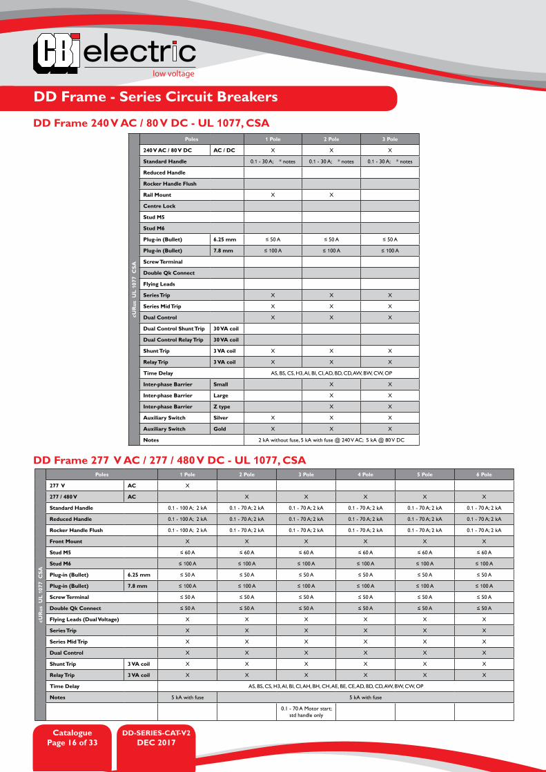
DD Frame 240 V AC / 80 V AC / DC - UL 489U
L 48
9
Poles 1 Pole 2 Pole 3 Pole
240 V / 80 V AC / DC X X X
Standard Handle
Reduced Handle
Rocker Handle Flush
Rail Mount 0.1 - 30 A; * notes 0.1 - 30 A; * notes 0.1 - 30 A; * notes
Centre Lock
Stud M5
Stud M6
Plug-in (Bullet) 6.25 mm ≤ 50 A ≤ 50 A ≤ 50 A
Plug-in (Bullet) 7.8 mm ≤ 100 A ≤ 100 A ≤ 100 A
Screw terminal
Double Qk connect
Flying leads
Series Trip X X X
Series Mid Trip X X X
Dual control X X X
Dual Control Shunt Trip 30 VA coil
Dual Control Relay Trip 30 VA coil
Shunt Trip 3 VA coil X X X
Relay Trip 3 VA coil X X X
Time Delay AS, BS, CS, AI, BI, CI, AD, BD, CD, AW, BW, CW, OP
Inter-phase Barrier Small X X
Inter-phase Barrier Large X X
Inter-phase Barrier Z type X X
Auxiliary Switch Silver X X X
Auxiliary Switch Gold X X X
Notes 5 kA @ 240 V AC 5 kA @ 240 V AC 5 kA @ 240 V AC
10 kA @ 80 V DC 10 kA @ 80 V DC 10 kA @ 80 V DC
IEC
/ E
N 6
0934
V
DE
CC
C C
E
Poles 1 Pole 1+N 2 Pole 2 Pole inertia Delay
240 V AC X X X
Standard Handle 0.1 - 50 A; 3 kA 0.1 - 50 A; 3 kA 0.1 - 50 A; 5 kA 0.1 - 50 A; 5 kA
Reduced Handle 0.1 - 50 A; 3 kA 0.1 - 50 A; 3 kA 0.1 - 50 A; 5 kA 0.1 - 50 A; 5 kA
Rocker Handle Flush 0.1 - 50 A; 3 kA 0.1 - 50 A; 3 kA 0.1 - 50 A; 5 kA 0.1 - 50 A; 5 kA
Front Mount
Centre Lock
Stud M5 ≤ 60 A ≤ 60 A ≤ 60 A ≤ 60 A
Stud M6 ≤ 100 A ≤ 100 A ≤ 100 A ≤ 100 A
Plug-in (Bullet) 6.25 mm ≤ 50 A ≤ 50 A ≤ 50 A ≤ 50 A
Plug-in (Bullet) 7.8 mm ≤ 100 A ≤ 100 A ≤ 100 A ≤ 100 A
Screw terminal ≤ 50 A ≤ 50 A ≤ 50 A ≤ 50 A
Double Qk connect ≤ 50 A ≤ 50 A ≤ 50 A ≤ 50 A
Flying leads X X X X
Series Trip X X X X
Series Mid Trip X X X X
Dual control X X X X
Dual Control Shunt Trip 30 VA coil
Dual Control Relay Trip 30 VA coil
Shunt Trip 3 VA coil X X X X
Relay Trip 3 VA coil X X X X
Time Delay AS, BS, CS, HE, AI, BI, CI, AH, BH, CH, AE, BE, CE, AD, BD, C, AW, BW, CW

DD-SERIES-CAT-V2DEC 2017
CataloguePage 14 of 33
low voltage
DD Frame - Series Circuit Breakers
DD Frame 240 V AC - IEC / EN 60934, VDE, CE, CCC
DD Frame 240 V AC / 80 V DC - IEC / EN 60934, VDE, CE, CCC
IEC
/ E
N 6
0934
V
DE
CC
C C
E
Poles 1 Pole 2 Pole 3 Pole 4 Pole
240 V AC X X X
Standard Handle 0.1 - 70 A: 3 kA 0.1 - 70 A: 3 kA 0.1 - 70 A: 3 kA 0.1 - 70 A: 3 kA
Reduced Handle 0.1 - 70 A: 3 kA 0.1 - 70 A: 3 kA 0.1 - 70 A: 3 kA 0.1 - 70 A: 3 kA
Rocker Handle Flush 0.1 - 70 A: 3 kA 0.1 - 70 A: 3 kA 0.1 - 70 A: 3 kA 0.1 - 70 A: 3 kA
Front Mount
Centre Lock
Stud M5 ≤ 60 A ≤ 60 A ≤ 60 A ≤ 60 A
Stud M6 ≤ 100 A ≤ 100 A ≤ 100 A ≤ 100 A
Plug-in (Bullet) 6.25 mm ≤ 50 A ≤ 50 A ≤ 50 A ≤ 50 A
Plug-in (Bullet) 7.8 mm ≤ 100 A ≤ 100 A ≤ 100 A ≤ 100 A
Screw terminal ≤ 50 A ≤ 50 A ≤ 50 A ≤ 50 A
Double Qk connect ≤ 50 A ≤ 50 A ≤ 50 A ≤ 50 A
Flying leads (dual voltage) X X X X
Series Trip X X X X
Series Mid Trip X X X X
Dual control X X X X
Dual Control Shunt Trip 30 VA coil
Dual Control Relay Trip 30 VA coil
Shunt Trip 3 VA coil X X X X
Relay Trip 3 VA coil X X X X
Time Delay AS, BS, CS, H3, AI,BI, CI, AH, BH, CH, AE, BE, CE, AD, BD, CD, AW, BW, CW
IEC
/ E
N 6
0934
V
DE
CC
C C
E
Poles 1 Pole 2 Pole 3 Pole
240 V / 80 V AC / DC X X X
I Amps
Reduced Handle
Rocker Handle Flush
kA with fuse
kA without fuse
Rail Mount 0.1 - 30 A; 3 kA 0.1 - 30 A; 3 kA 0.1 - 30 A; 3 kA
Centre Lock
Stud M5
Stud M6
Plug-in (Bullet) 6.25 mm ≤ 50 A ≤ 50 A ≤ 50 A
Plug-in (Bullet) 7.8 mm ≤ 100 A ≤ 100 A ≤ 100 A
Screw terminal
Double Qk connect
Flying leads
Series Trip X X X
Series Mid Trip X X X
Dual control X X X
Dual Control Shunt Trip 30 VA coil
Dual Control Relay Trip 30 VA coil
Shunt Trip 3 VA coil X X X
Relay Trip 3 VA coil X X X
Time Delay AS, BS, CS, AI, BI, CI, AD, BD, CD, AW, BW, CW, OP
Inter-phase Barrier Small X X
Inter-phase Barrier Large X X
Inter-phase Barrier Z type X X
Auxiliary Switch Silver X X X
Auxiliary Switch Gold X X X

low voltage
DD-SERIES-CAT-V2DEC 2017
CataloguePage 15 of 33
DD Frame - Series Circuit Breakers
DD Frame 240 V AC - IEC / EN 60947-3, VDE, CE
DD Frame 240 V AC - IEC / EN 60947-2, VDE, CCC
IEC
/ E
N 6
0947
-2, V
DE
, CC
C
Poles 1 Pole 1+N 2 Pole 2 Pole Inertia Delay
240 V AC X X X
Standard Handle 0.1 - 50 A; 5 kA 0.1 - 50 A; 5 kA 0.1 - 50 A; 5 kA 0.1 - 40 A; 5 kA
Reduced Handle 0.1 - 50 A; 5 kA 0.1 - 50 A; 5 kA 0.1 - 50 A; 5 kA 0.1 - 40 A; 5 kA
Rocker Handle Flush 0.1 - 50 A; 5 kA 0.1 - 50 A; 5 kA 0.1 - 50 A; 5 kA 0.1 - 40 A; 5 kA
Front Mount
Centre Lock
Stud M5 ≤ 60 A ≤ 60 A ≤ 60 A ≤ 60 A
Stud M6 ≤ 100 A ≤ 100 A ≤ 100 A ≤ 100 A
Plug-in (Bullet) 6.25 mm ≤ 50 A ≤ 50 A ≤ 50 A ≤ 50 A
Plug-in (Bullet) 7.8 mm ≤ 100 A ≤ 100 A ≤ 100 A ≤ 100 A
Screw terminal ≤ 50 A ≤ 50 A ≤ 50 A ≤ 50 A
Double Qk connect ≤ 50 A ≤ 50 A ≤ 50 A ≤ 50 A
Flying leads X X X X
Series Trip X X X X
Series Mid Trip X X X X
Dual control X X X X
Dual Control Shunt Trip 30 VA coil
Dual Control Relay Trip 30 VA coil
Shunt Trip 3 VA coil X X X X
Relay Trip 3 VA coil X X X X
Time Delay AS, BS, CS, HE, AI, BI, CI, AH, BH, CH, AE, BE, CE, AD, BD, C, AW, BW, CW
IEC
/ E
N 6
0947
-3
VD
E C
E
Poles 1 Pole 2 Pole
240 V AC X X
Standard Handle 50 A; 0.6 kA 50 A; 0.6 kA
Reduced Handle 50 A; 0.6 kA 50 A; 0.6 kA
Rocker Handle Flush
kA with fuse
kA without fuse
Front Mount
Centre Lock
Stud M5 ≤ 60 A ≤ 60 A
Stud M6 ≤ 100 A ≤ 100 A
Plug-in (Bullet) 6.25 mm ≤ 50 A ≤ 50 A
Plug-in (Bullet) 7.8 mm ≤ 100 A ≤ 100 A
Screw terminal ≤ 50 A ≤ 50 A
Double Qk connect
Flying Leads
Switch X X
Series Mid Trip
Dual control
Dual Control Shunt Trip 30 VA coil
Dual Control Relay Trip 30 VA coil
Shunt Trip 3 VA coil
Relay Trip 3 VA coil
Time Delay OX
Inter-phase Barrier Small X
Inter-phase Barrier Large X
Inter-phase Barrier Z type X
Auxiliary Switch Silver X X
Auxiliary Switch Gold X X
DD-SERIES-CAT-V2DEC 2017
CataloguePage 16 of 33
low voltage
DD Frame - Series Circuit Breakers
DD Frame 240 V AC / 80 V DC - UL 1077, CSA
DD Frame 277 V AC / 277 / 480 V DC - UL 1077, CSA
cUR
us U
L 10
77 C
SA
Poles 1 Pole 2 Pole 3 Pole 4 Pole 5 Pole 6 Pole
277 V AC X
277 / 480 V AC X X X X X
Standard Handle 0.1 - 100 A; 2 kA 0.1 - 70 A; 2 kA 0.1 - 70 A; 2 kA 0.1 - 70 A; 2 kA 0.1 - 70 A; 2 kA 0.1 - 70 A; 2 kA
Reduced Handle 0.1 - 100 A; 2 kA 0.1 - 70 A; 2 kA 0.1 - 70 A; 2 kA 0.1 - 70 A; 2 kA 0.1 - 70 A; 2 kA 0.1 - 70 A; 2 kA
Rocker Handle Flush 0.1 - 100 A; 2 kA 0.1 - 70 A; 2 kA 0.1 - 70 A; 2 kA 0.1 - 70 A; 2 kA 0.1 - 70 A; 2 kA 0.1 - 70 A; 2 kA
Front Mount X X X X X X
Stud M5 ≤ 60 A ≤ 60 A ≤ 60 A ≤ 60 A ≤ 60 A ≤ 60 A
Stud M6 ≤ 100 A ≤ 100 A ≤ 100 A ≤ 100 A ≤ 100 A ≤ 100 A
Plug-in (Bullet) 6.25 mm ≤ 50 A ≤ 50 A ≤ 50 A ≤ 50 A ≤ 50 A ≤ 50 A
Plug-in (Bullet) 7.8 mm ≤ 100 A ≤ 100 A ≤ 100 A ≤ 100 A ≤ 100 A ≤ 100 A
Screw Terminal ≤ 50 A ≤ 50 A ≤ 50 A ≤ 50 A ≤ 50 A ≤ 50 A
Double Qk Connect ≤ 50 A ≤ 50 A ≤ 50 A ≤ 50 A ≤ 50 A ≤ 50 A
Flying Leads (Dual Voltage) X X X X X X
Series Trip X X X X X X
Series Mid Trip X X X X X X
Dual Control X X X X X X
Shunt Trip 3 VA coil X X X X X X
Relay Trip 3 VA coil X X X X X X
Time Delay AS, BS, CS, H3, AI, BI, CI, AH, BH, CH, AE, BE, CE, AD, BD, CD, AW, BW, CW, OP
Notes 5 kA with fuse 5 kA with fuse
0.1 - 70 A Motor start; std handle only
cUR
us U
L 10
77 C
SAPoles 1 Pole 2 Pole 3 Pole
240 V AC / 80 V DC AC / DC X X X
Standard Handle 0.1 - 30 A; * notes 0.1 - 30 A; * notes 0.1 - 30 A; * notes
Reduced Handle
Rocker Handle Flush
Rail Mount X X
Centre Lock
Stud M5
Stud M6
Plug-in (Bullet) 6.25 mm ≤ 50 A ≤ 50 A ≤ 50 A
Plug-in (Bullet) 7.8 mm ≤ 100 A ≤ 100 A ≤ 100 A
Screw Terminal
Double Qk Connect
Flying Leads
Series Trip X X X
Series Mid Trip X X X
Dual Control X X X
Dual Control Shunt Trip 30 VA coil
Dual Control Relay Trip 30 VA coil
Shunt Trip 3 VA coil X X X
Relay Trip 3 VA coil X X X
Time Delay AS, BS, CS, H3, AI, BI, CI, AD, BD, CD, AW, BW, CW, OP
Inter-phase Barrier Small X X
Inter-phase Barrier Large X X
Inter-phase Barrier Z type X X
Auxiliary Switch Silver X X X
Auxiliary Switch Gold X X X
Notes 2 kA without fuse, 5 kA with fuse @ 240 V AC; 5 kA @ 80 V DC
low voltage
DD-SERIES-CAT-V2DEC 2017
CataloguePage 17 of 33
DD Frame - Series Circuit Breakers
PERCENTAGE OF RATED CURRENT
TR
IP T
IME
IN S
ECO
ND
S
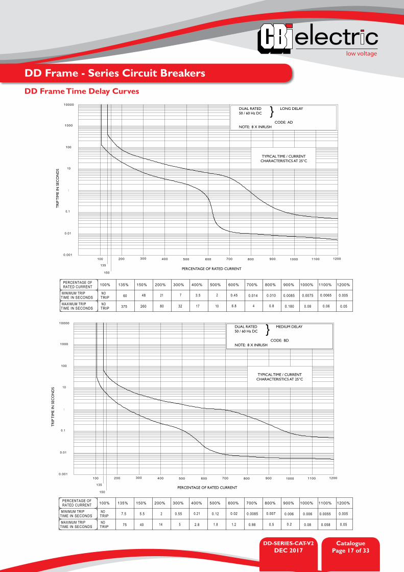
TYPICAL TIME / CURRENT CHARACTERISTICS AT 25°C
DUAL RATED LONG DELAY50 / 60 Hz DC
CODE: ADNOTE: 8 X INRUSH
}
PERCENTAGE OF RATED CURRENT
TR
IP T
IME
IN S
ECO
ND
S
TYPICAL TIME / CURRENT CHARACTERISTICS AT 25°C
DUAL RATED MEDIUM DELAY50 / 60 Hz DC
CODE: BDNOTE: 8 X INRUSH
}
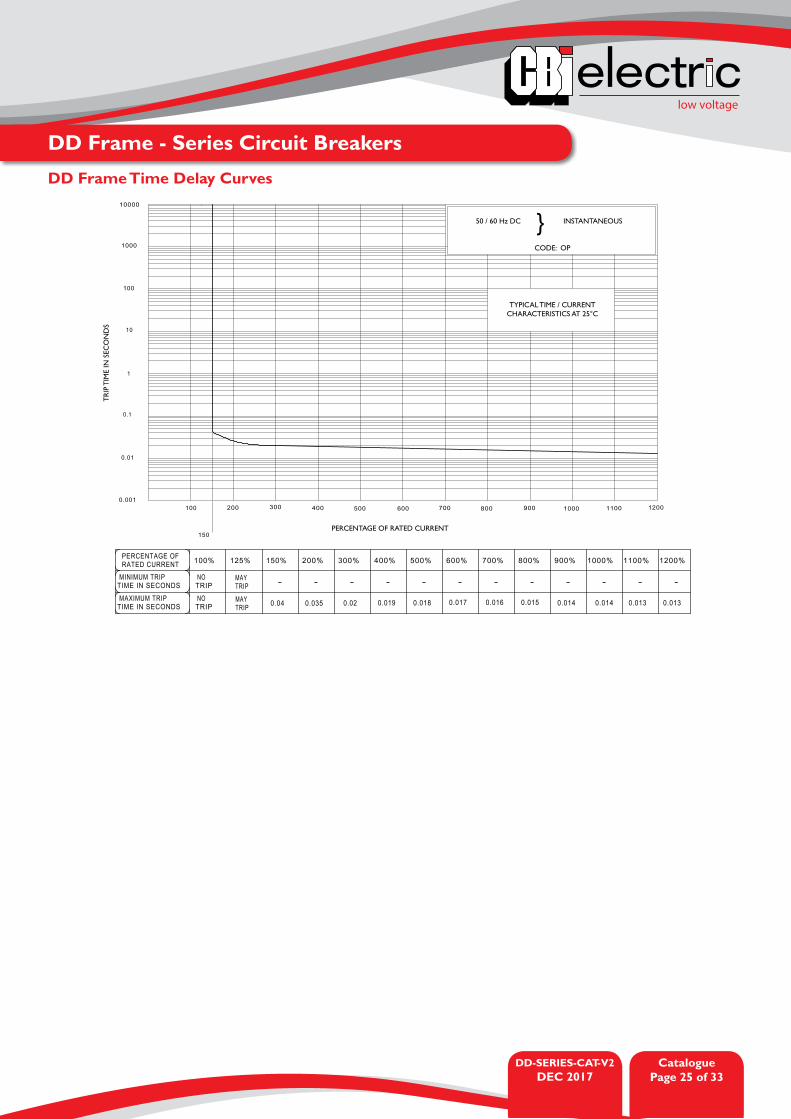
DD Frame Time Delay Curves
DD-SERIES-CAT-V2DEC 2017
CataloguePage 18 of 33
low voltage
DD Frame - Series Circuit Breakers
PERCENTAGE OF RATED CURRENT
TR
IP T
IME
IN S
ECO
ND
S
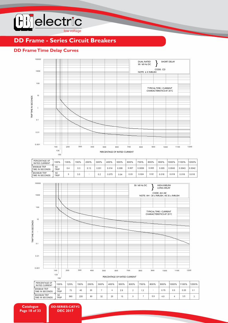
TYPICAL TIME / CURRENT CHARACTERISTICS AT 25°C
DUAL RATED SHORT DELAY50 / 60 Hz DC
CODE: CDNOTE: 6 X INRUSH
}
DD Frame Time Delay Curves
PERCENTAGE OF RATED CURRENT
TR
IP T
IME
IN S
ECO
ND
S
TYPICAL TIME / CURRENT CHARACTERISTICS AT 25°C
50 / 60 Hz DC HIGH-INRUSH LONG DELAY
CODE: AH /AENOTE: AH - 20 x INRUSH, AE 35 x INRUSH
}
low voltage
DD-SERIES-CAT-V2DEC 2017
CataloguePage 19 of 33
DD Frame - Series Circuit Breakers
PERCENTAGE OF RATED CURRENT
TR
IP T
IME
IN S
ECO
ND
S
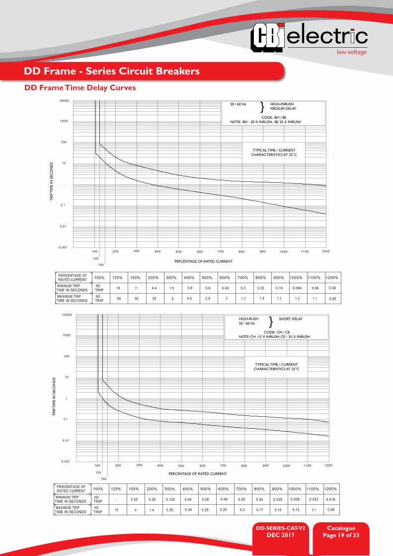
TYPICAL TIME / CURRENT CHARACTERISTICS AT 25°C
50 / 60 Hz HIGH-INRUSH MEDIUM DELAY
CODE: BH / BENOTE: BH - 20 X INRUSH, BE 25 X INRUSH
}
PERCENTAGE OF RATED CURRENT
TR
IP T
IME
IN S
ECO
ND
S
TYPICAL TIME / CURRENT CHARACTERISTICS AT 25°C
HIGH-RUSH SHORT DELAY 50 / 60 Hz
CODE: CH / CENOTE: CH -15 X INRUSH, CE - 35 X INRUSH
}
DD Frame Time Delay Curves

DD-SERIES-CAT-V2DEC 2017
CataloguePage 20 of 33
low voltage
DD Frame - Series Circuit Breakers
PERCENTAGE OF RATED CURRENT
TR
IP T
IME
IN S
ECO
ND
S
TYPICAL TIME / CURRENT CHARACTERISTICS AT 25°C
50 / 60 Hz DC LONG DELAY WITH INRUSH PULSE TOLERANCE
CODE: AINOTE: 20 x INRUSH
}
PERCENTAGE OF RATED CURRENT
TR
IP T
IME
IN S
ECO
ND
S
TYPICAL TIME / CURRENT CHARACTERISTICS AT 25°C
50 / 60 Hz DC MEDIUM DELAY WITH INRUSH PULSE TOLERANCE
CODE: BINOTE: 20 X INRUSH
}
DD Frame Time Delay Curves

low voltage
DD-SERIES-CAT-V2DEC 2017
CataloguePage 21 of 33
DD Frame - Series Circuit Breakers
PERCENTAGE OF RATED CURRENT
TR
IP T
IME
IN S
ECO
ND
S
TYPICAL TIME / CURRENT CHARACTERISTICS AT 25°C
50 / 60 Hz DC LONG DELAY WITH INRUSH PULSE TOLERANCE
CODE: CINOTE: 15 x INRUSH
}
PERCENTAGE OF RATED CURRENT
TR
IP T
IME
IN S
ECO
ND
S
TYPICAL TIME / CURRENT CHARACTERISTICS AT 25°C
50 / 60 Hz DC LONG DELAY
CODE: ASNOTE: 8 x INRUSH
}
DD Frame Time Delay Curves
DD-SERIES-CAT-V2DEC 2017
CataloguePage 22 of 33
low voltage
DD Frame - Series Circuit Breakers
PERCENTAGE OF RATED CURRENT
TR
IP T
IME
IN S
ECO
ND
S
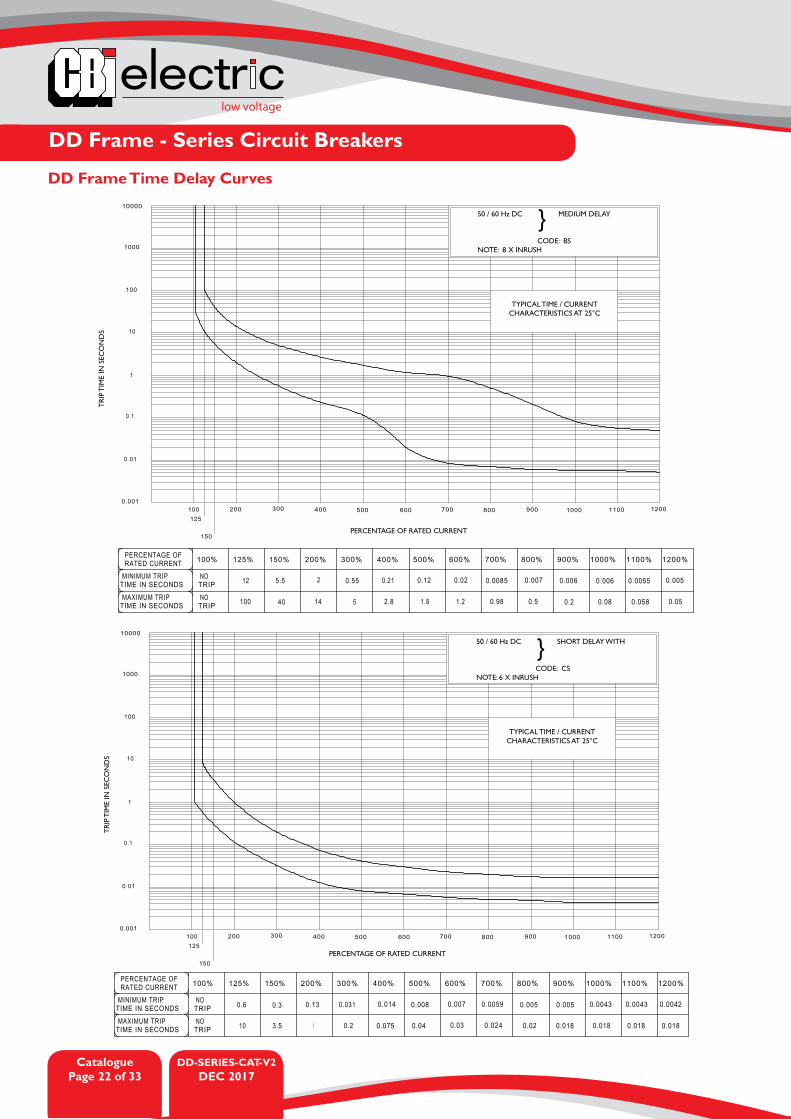
TYPICAL TIME / CURRENT CHARACTERISTICS AT 25°C
50 / 60 Hz DC MEDIUM DELAY
CODE: BSNOTE: 8 X INRUSH
}
PERCENTAGE OF RATED CURRENT
TR
IP T
IME
IN S
ECO
ND
S
TYPICAL TIME / CURRENT CHARACTERISTICS AT 25°C
50 / 60 Hz DC SHORT DELAY WITH
CODE: CSNOTE: 6 X INRUSH
}
DD Frame Time Delay Curves

low voltage
DD-SERIES-CAT-V2DEC 2017
CataloguePage 23 of 33
DD Frame - Series Circuit Breakers
PERCENTAGE OF RATED CURRENT
TR
IP T
IME
IN S
ECO
ND
S
TYPICAL TIME / CURRENT CHARACTERISTICS AT 25°C
DUAL RATED LONG DELAY WITH50 / 60 Hz DC INRUSH PULSE TOLERANCE
CODE: AWNOTE: 20 x INRUSH
}
PERCENTAGE OF RATED CURRENT
TR
IP T
IME
IN S
ECO
ND
S
TYPICAL TIME / CURRENT CHARACTERISTICS AT 25°C
DUAL RATED MEDIUM DELAY WITH50 / 60 Hz DC INRUSH PULSE TOLERANCE
CODE: BWNOTE: 20 X INRUSH
}
DD Frame Time Delay Curves

DD-SERIES-CAT-V2DEC 2017
CataloguePage 24 of 33
low voltage
DD Frame - Series Circuit Breakers
PERCENTAGE OF RATED CURRENT
TR
IP T
IME
IN S
ECO
ND
S
TYPICAL TIME / CURRENT CHARACTERISTICS AT 25°C
DUAL RATED SHORT DELAY WITH50 / 60 Hz INSTANTANEOUS
CODE: CWNOTE: 15 X INRUSH
}
% %%%%%%%%%%%%%PERCENTAGE OF RATED CURRENT
MINIMUM TRIP TIMEIN SECONDS
MAXIMUM TRIP TIMEIN SECONDS
NOTRIPNOTRIP
PERCENTAGE OF RATED CURRENT
TR
IP T
IME
IN S
ECO
ND
S
TYPICAL TIME / CURRENT CHARACTERISTICS AT 25°C
50 / 60 Hz DC SHORT DELAY
CODE: H3
}
DD Frame Time Delay Curves
low voltage
DD-SERIES-CAT-V2DEC 2017
CataloguePage 25 of 33
DD Frame - Series Circuit Breakers
PERCENTAGE OF RATED CURRENT
TR
IP T
IME
IN S
ECO
ND
S
TYPICAL TIME / CURRENT CHARACTERISTICS AT 25°C
50 / 60 Hz DC INSTANTANEOUS
CODE: OP
}
DD Frame Time Delay Curves

DD-SERIES-CAT-V2DEC 2017
CataloguePage 26 of 33
low voltage
DD Frame - Series Circuit Breakers
--
- - -
-
DD
Fra
me
Stan
dard
Han
dle
Out
line
Dim
ensi
ons

low voltage
DD-SERIES-CAT-V2DEC 2017
CataloguePage 27 of 33
DD Frame - Series Circuit Breakers
-
--
- - -
DD
Fra
me
Stan
dard
Red
uced
Han
dle
Out
line
Dim
ensi
ons
DD-SERIES-CAT-V2DEC 2017
CataloguePage 28 of 33
low voltage
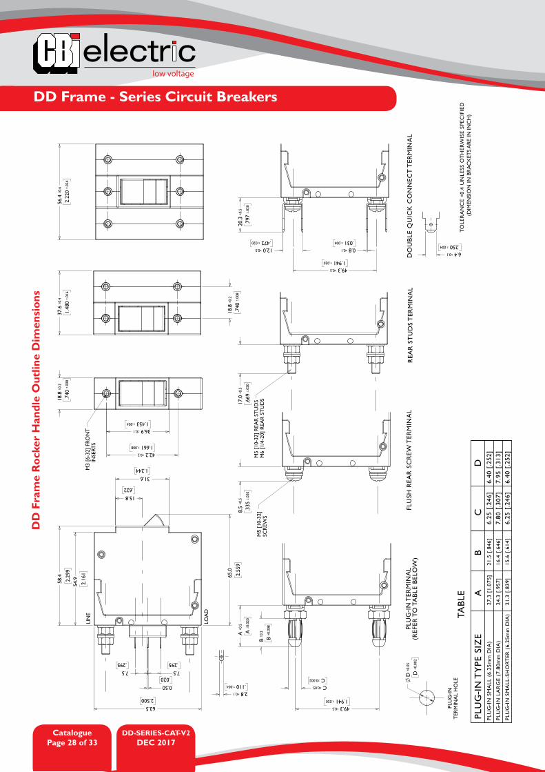
DD Frame - Series Circuit Breakers
-
--
- - -
DD
Fra
me
Roc
ker
Han
dle
Out
line
Dim
ensi
ons

low voltage
DD-SERIES-CAT-V2DEC 2017
CataloguePage 29 of 33
DD Frame - Series Circuit Breakers
-
--
- - -
DD
Fra
me
Cut
-off
Han
dle
Out
line
Dim
ensi
ons
DD-SERIES-CAT-V2DEC 2017
CataloguePage 30 of 33
low voltage
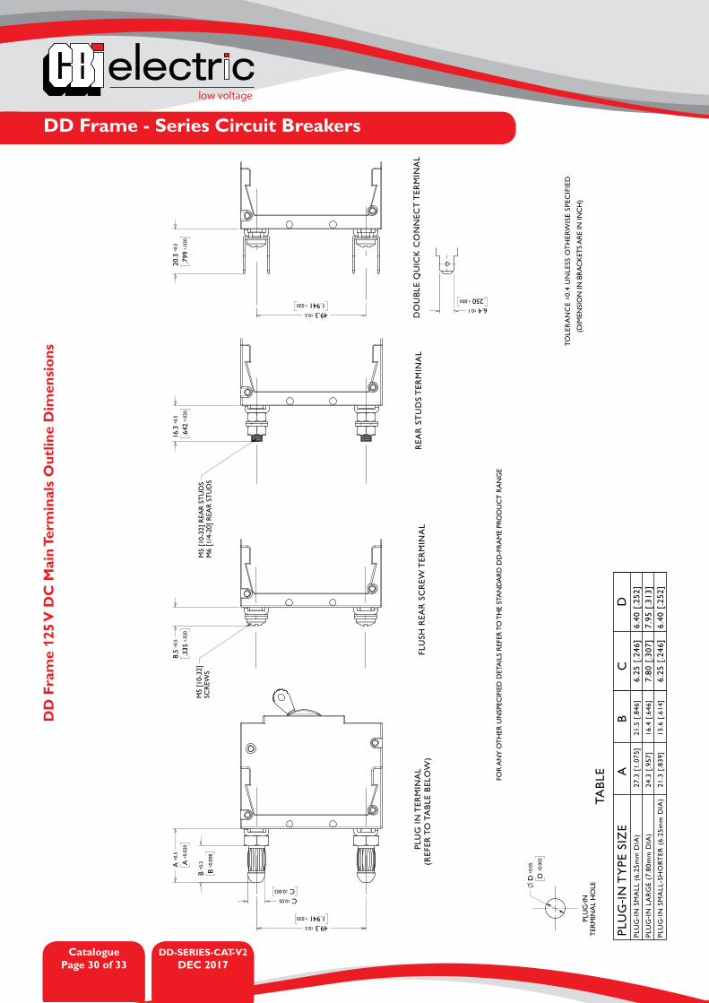
DD Frame - Series Circuit Breakers
--
- - -
DD
Fra
me
125
V D
C M
ain
Term
inal
s O
utlin
e D
imen
sion
s

low voltage
DD-SERIES-CAT-V2DEC 2017
CataloguePage 31 of 33
DD Frame - Series Circuit Breakers
DD
Fra
me
Rel
ay a
nd S
hunt
Tri
p U
nits
Out
line
Dim
ensi
ons

DD-SERIES-CATOCT 2016
CataloguePage 32 of 33
low voltage
DD Frame - Series Circuit Breakers
DD
Fra
me
Rea
r In
ter-
Pha
se B
arri
er a
nd T
erm
inal
Cov
er O
utlin
e D
imen
sion
s

AUSTRALIACBI-electric: Australia27 Wedgewood Rd, Hallam Victoria 3803 AustraliaTel: +61 3 8752 9300Fax: +61 3 9796 5407Email: [email protected]: www.cbi-electric.com.au
SOUTH AFRICACBI-electric: low voltageTripswitch Drive ElandsfonteinGauteng South AfricaTel: +27 11 928 2000Fax: + 27 11 392 2354Email: [email protected] [email protected]: www.cbi-lowvoltage.com
USACBI-electric: North America35 E. Uwchlan Ave Suite 328Exton PA 19341 USATel: +1 610 524 9949Fax: +1 610 524 9945E-mail: [email protected]: www.cbibreakers.com
Please review our Customer Terms and Conditions on www.cbi-lowvoltage.co.zaAll rights reserved. Unless otherwise indicated, all materials on these pages are copyrighted by CBI (Pty) Ltd. No part of these pages, either text or image may be used for any purpose other than personal use. Therefore, reproduction, modification, storage in a retrieval system or retransmission, in any form or by any means, electronic, mechanical or otherwise, for reasons other than personal use, is strictly prohibited without prior written permission. CBI (Pty) Ltd reserves the right to alter any details of this document without notice and while every effort is made to ensure the accuracy of the content, no warranty is given as to the accuracy of this document and no responsibility will be accepted for error or misinterpretation and any resulting loss.
© 2016.09 CBI (Pty) Ltd. All Rights Reserved.
DD-SERIES-CATOCT 2016
low voltage
CataloguePage 33 of 33
A member of the Group
DD Frame - Series Circuit Breakers
DD
Fra
me
Rai
l Mou
ntin
g U
nits
Out
line
Dim
ensi
ons