Embed Size (px)
Citation preview
DD150-U
Bedienungsanleitung deOperating instructions enMode d’emploi frIstruzioni d’uso itManual de instrucciones esManual de instruções ptGebruiksaanwijzing nlBrugsanvisning daBruksanvisning svBruksanvisning noKäyttöohje fiΟδηγιες χρησεως elHasználati utasítás huInstrukcja obsługi plИнструкция по зксплуатации ruNávod k obsluze csNávod na obsluhu skUpute za uporabu hrNavodila za uporabo slLietošanas pamācība lvInstrukcija ltKasutusjuhend et
Printed: 22.11.2013 | Doc-Nr: PUB / 5069532 / 000 / 06Printed: 22.11.2013 | Doc-Nr: PUB / 5069532 / 000 / 07
1
Printed: 22.11.2013 | Doc-Nr: PUB / 5069532 / 000 / 06Printed: 22.11.2013 | Doc-Nr: PUB / 5069532 / 000 / 07

2
Printed: 22.11.2013 | Doc-Nr: PUB / 5069532 / 000 / 06Printed: 22.11.2013 | Doc-Nr: PUB / 5069532 / 000 / 07

3
4 5
Printed: 22.11.2013 | Doc-Nr: PUB / 5069532 / 000 / 06Printed: 22.11.2013 | Doc-Nr: PUB / 5069532 / 000 / 07

6
8
9 10
11 12
7
Printed: 22.11.2013 | Doc-Nr: PUB / 5069532 / 000 / 06Printed: 22.11.2013 | Doc-Nr: PUB / 5069532 / 000 / 07

16
17 18
19 20
14
15
13
Printed: 22.11.2013 | Doc-Nr: PUB / 5069532 / 000 / 06Printed: 22.11.2013 | Doc-Nr: PUB / 5069532 / 000 / 07

21 22
23 24
25 26
Printed: 22.11.2013 | Doc-Nr: PUB / 5069532 / 000 / 06Printed: 22.11.2013 | Doc-Nr: PUB / 5069532 / 000 / 07
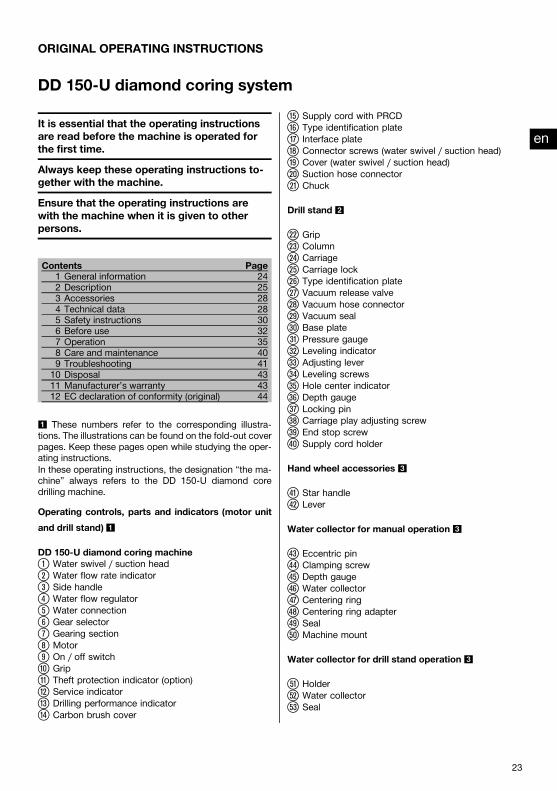
ORIGINAL OPERATING INSTRUCTIONS
DD 150‑U diamond coring system
It is essential that the operating instructionsare read before the machine is operated forthe first time.Always keep these operating instructions to-gether with the machine.Ensure that the operating instructions arewith the machine when it is given to otherpersons.
Contents Page1 General information 242 Description 253 Accessories 284 Technical data 285 Safety instructions 306 Before use 327 Operation 358 Care and maintenance 409 Troubleshooting 4110 Disposal 4311 Manufacturer’s warranty 4312 EC declaration of conformity (original) 44
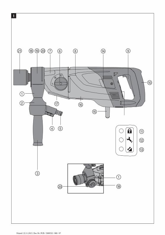
1 These numbers refer to the corresponding illustra-tions. The illustrations can be found on the fold-out coverpages. Keep these pages open while studying the oper-ating instructions.In these operating instructions, the designation “the ma-chine” always refers to the DD 150-U diamond coredrilling machine.
Operating controls, parts and indicators (motor unitand drill stand) 1
DD 150‑U diamond coring machine@
Water swivel / suction head;
Water flow rate indicator=
Side handle%
Water flow regulator&
Water connection(
Gear selector)
Gearing section+
Motor§
On / off switch/
Grip:
Theft protection indicator (option)·
Service indicator$
Drilling performance indicator£
Carbon brush cover
|Supply cord with PRCD
¡Type identification plate
QInterface plate
WConnector screws (water swivel / suction head)
ECover (water swivel / suction head)
RSuction hose connector
TChuck
Drill stand 2
ZGrip
UColumn
ICarriage
OCarriage lock
PType identification plate
ÜVacuum release valve
[Vacuum hose connector
]Vacuum seal
ÆBase plate
ºPressure gauge
•Leveling indicator
AAdjusting lever
SLeveling screws
DHole center indicator
FDepth gauge
GLocking pin
HCarriage play adjusting screw
JEnd stop screw
KSupply cord holder
Hand wheel accessories 3
LStar handle
ÖLever
Water collector for manual operation 3
ÄEccentric pin
†Clamping screw
ŒDepth gauge
ÅWater collector
ªCentering ring
^Centering ring adapter
YSeal
XMachine mount
Water collector for drill stand operation 3
CHolder
VWater collector
BSeal
en
23
Printed: 22.11.2013 | Doc-Nr: PUB / 5069532 / 000 / 06Printed: 22.11.2013 | Doc-Nr: PUB / 5069532 / 000 / 07

Various accessories 3
NJack screw
MWheel assembly
?Rota-Rail
!Switch lock for drill stand operation
—Vacuum base plate
1 General information1.1 Safety notices and their meaningDANGERDraws attention to imminent danger that will lead toserious bodily injury or fatality.
WARNINGDraws attention to a potentially dangerous situation thatcould lead to serious personal injury or fatality.
CAUTIONDraws attention to a potentially dangerous situation thatcould lead to slight personal injury or damage to theequipment or other property.
NOTEDraws attention to an instruction or other useful informa-tion.
1.2 Explanation of the pictograms and otherinformation
Prohibition signs
Transport bycrane is notpermissible.
Warning signs
Generalwarning
Warning:electricity
Warning: hotsurface
Obligation signs
Wear eyeprotection.
Wear a hardhat.
Wear earprotection.
Wearprotectivegloves.
Wear safetyshoes.
Wearbreathingprotection.
Symbols
Read theoperatinginstructionsbefore use.
Lock symbol Equippedwith theftprotectionsystem
Return wastematerial forrecycling.
Serviceindicator
Drillingperformanceindicator
Amps Volts
en
24
Printed: 22.11.2013 | Doc-Nr: PUB / 5069532 / 000 / 06Printed: 22.11.2013 | Doc-Nr: PUB / 5069532 / 000 / 07

VACUUM
VACUUM
Alternatingcurrent
Watts Hertz Nominalspeed underno load
Diameter Millimeters Revolutionsper minute
On the drill stand and the vacuum base plate
Upper: An additional means of securing the drill standmust be employed when the machine is used for hori-zontal drilling with the vacuum securing method.Lower: Use of the vacuum securing method for overheaddrilling with the drill stand is not permissible.
On the machine
Use of the water collection system in conjunction witha wet-type industrial vacuum cleaner is a mandatoryrequirement for working on ceilings.
Location of identification data on the machineThe type designation and serial number can be found onthe type identification plate on the machine. Make a noteof this data in your operating instructions and always referto it when making an enquiry to your Hilti representativeor service department.
Type:
Generation: 01
Serial no.:
2 Description2.1 Use of the product as directedThe DD 150-U is an electrically powered diamond core drilling machine for hand-guided wet and dry drilling of throughholes or blind holes (e.g. anchor holes) and for wet drilling of through holes or blind holes in (reinforced) mineralmaterials with the machine mounted on a drill stand.When mounted on the drill stand, the system must be adequately secured to the working surface with an anchor orvacuum base plate before use.Drilling into materials that produce electrically conductive dust (e.g. magnesium) is not permissible.Where possible, use a suitable industrial vacuum cleaner when working with the system, e.g. the Hilti VC 20‑U/UM,VC 40‑U/UM or VC 60‑U.To avoid injury, use only genuine Hilti core bits and DD 150-U accessories.Observe the safety rules and operating instructions for the accessories used.Observe the information printed in the operating instructions concerning operation, care and maintenance.Nationally applicable industrial safety regulations must be observed.The machine, accessories and cutting tools may present hazards when handled incorrectly by untrained personnel orwhen used not as directed.Use of the water collection system in conjunction with a wet-type industrial vacuum cleaner is a mandatory requirementfor wet drilling overhead.
en
25
Printed: 22.11.2013 | Doc-Nr: PUB / 5069532 / 000 / 06Printed: 22.11.2013 | Doc-Nr: PUB / 5069532 / 000 / 07

Use of the vacuum fastening method for overhead drilling is prohibited.An additional means of securing the drill stand must be employed when the machine is secured with the vacuum baseplate (accessory) for horizontal drilling.Do not strike the base plate with a hammer or other heavy object when making adjustments to it.Tampering with or modification of the machine, drill stand and accessories is strictly prohibited.
WARNINGThe machine may be operated only when connected to an adequately-rated electric supply equipped with anearth (ground) conductor.
WARNINGDrilling into materials hazardous to the health (e.g. asbestos) is not permissible.
DANGERUse only the genuine Hilti accessories or ancillary equipment listed in the operating instructions. Use ofaccessories or ancillary equipment not listed in the operating instructions may present a risk of personal injury.
2.2 Use of the machine with various items of equipment
With / without the drill stand With / without thesystem Core bit diameter Drilling direction
Hand-guided / dry With dust removal sys-tem
37…162 mm All directions
Hand-guided / wet Without water collec-tion system
8…132 mm Not upwards
Hand-guided / wet With water collectionsystem
8…62 mm All directions
On drill stand / wet Without water collec-tion system
12…162 mm Not upwards
On drill stand / wet With water collectionsystem
12…162 mm All directions
2.3 Gears and corresponding core bit diametersOn drill stand, wet
Gear Core bit diameters(mm)
Core bit diameters(inches)
Speed under no load/min
1 102…162 4…6¹⁄₄ 7802 28…87 1¹⁄₈…3¹⁄₂ 1,5203 12…25 ¹⁄₂…1 2,850
Hand-guided, wet
Gear Core bit diameters(mm)
Core bit diameters(inches)
Speed under no load/min
1 121…131 4³⁄₄…5 7802 41…111 1⁵⁄₈…4³⁄₈ 1,5203 8…36 ¹⁄₂…1¹⁄₂ 2,850
Hand-guided, dry, HDM
Gear Core bit diameters(mm)
Core bit diameters(inches)
Speed under no load/min
1 122…162 4³⁄₄…6¹⁄₄ 7802 67…112 2⁵⁄₈…4¹⁄₄ 1,5203 37…62 1¹⁄₂…2¹⁄₂ 2,850
en
26
Printed: 22.11.2013 | Doc-Nr: PUB / 5069532 / 000 / 06Printed: 22.11.2013 | Doc-Nr: PUB / 5069532 / 000 / 07

Hand-guided, dry, PCM
Gear Core bit diameters(mm)
Core bit diameters(inches)
Speed under no load/min
1 52…162 2…6¹⁄₄ 780
2.4 Status indicatorLED indicators State Description / informationTheft protection indicator (11) Blinking yellow light The machine's theft protection system
is active and must be unlocked with theTPS key.
Service indicator (12) Red light and the machinestarts
The carbon brushes are badly worn.After the lamp lights for the first time,the machine may continue to be usedfor several hours before the automaticcut-out is activated. Have the carbonbrushes changed in good time so thatthe machine is always ready for use.
Red light and the machinedoesn’t start
The carbon brushes must be changed.
Blinking red light Temporary fault, see Troubleshootingsection.
Drilling performance indicator (13)(only in conjunction with the drillstand)
Orange light Contact pressure too lowGreen light Optimum contact pressureRed light Contact pressure too high
NOTEWhen using the machine for hand-guided coring, the drilling performance indicator gives no indication of the optimumpressure.
2.5 TPS theft protection system (optional)The machine may be optionally equipped with the TPS theft protection system. If equipped with this feature, themachine can be unlocked and made ready for operation only through use of the corresponding TPS key.
2.6 Items supplied as standard1 Machine1 Operating instructions1 Hilti toolbox or cardboard box
2.7 Using extension cordsUse only extension cords of a type approved for the application and with conductors of adequate gauge.Recommended minimum conductor gauge (cross section) and max. cable lengthsConductor cross section 1.5 mm² 2.5 mm² 3.5 mm² 4.0 mm²Mains voltage 100 V Not recommen-
dedNot recommen-ded
25 Not recommen-ded
Mains voltage 110 V Not recommen-ded
15 m Not recommen-ded
30 m
Mains voltage 127 V Not recommen-ded
20 m Not recommen-ded
35 m
Mains voltage 220 V 35 m 65 m Not recommen-ded
105 m
Mains voltage 230 V 40 m 70 m Not recommen-ded
110 m
en
27
Printed: 22.11.2013 | Doc-Nr: PUB / 5069532 / 000 / 06Printed: 22.11.2013 | Doc-Nr: PUB / 5069532 / 000 / 07

Conductor cross section 1.5 mm² 2.5 mm² 3.5 mm² 4.0 mm²Mains voltage 240 V 40 m 70 m Not recommen-
ded110 m
Do not use extension cords with 1.25 mm² conductors. Use only extension cords equipped with an earth conductor.
2.8 Using a generator or transformerThis machine may be powered by a generator or transformer when the following conditions are fulfilled: The unit mustprovide a power output in watts of at least twice the value printed on the type identification plate on the machine. Theoperating voltage must remain within +5% and -15% of the rated voltage at all times, frequency must be in the 50 – 60Hz range and never above 65 Hz, and the unit must be equipped with automatic voltage regulation and starting boost.
NOTESwitching other machines or appliances on and off can cause undervoltage and/or overvoltage peaks which coulddamage the machine. Never operate other machines from the generator/transformer at the same time.
3 AccessoriesDesignation Short designation DescriptionTPS theft protection system withcompany card, company remoteand TPS‑K key
Option
Water collection system (for usewith the drill stand)Water collection system (for hand-guided drilling)Drill stand (with combination baseplate and tilt mechanism)Drill stand with anchor base plateVacuum base plate DD-ST-120/160-VBPDepth gaugeHand wheel (lever)Hand wheel (star handle)Core bit extension (BI+)Jack screwRota-Rail (column swivel)
4 Technical dataRight of technical changes reserved.
NOTEThe machine is available in various voltage ratings. Please refer to the machine’s type identification plate for details ofits rated voltage and rated input power.
Ratedvoltage[V]
100 110 GB 110 TW 120 127 220 230 240
Ratedcurrent[A]
15 16 15 19.5 18.5 10 10.3 9.9
en
28
Printed: 22.11.2013 | Doc-Nr: PUB / 5069532 / 000 / 06Printed: 22.11.2013 | Doc-Nr: PUB / 5069532 / 000 / 07
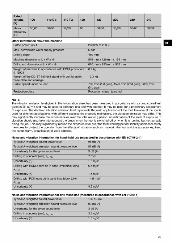
Ratedvoltage[V]
100 110 GB 110 TW 120 127 220 230 240
Mainsfrequency[Hz]
50/60 50/60 50/60 60 50/60 50/60 50/60 50/60
Other information about the machineRated power input 2200 W at 230 VMax. permissible water supply pressure 6 barDrilling depth 450 mmMachine dimensions (L x W x H) 516 mm x 129 mm x 159 mmDrill stand dimensions (L x W x H) 610 mm x 250 mm x 952 mmWeight of machine in accordance with EPTA procedure01/2003
8.2 kg
Weight of the DD-ST 150 drill stand with combinationbase plate and carriage
13.3 kg
Rated speed under no load 780 /min (1st gear), 1520 /min (2nd gear), 2850 /min(3rd gear)
Protection class Protection class I (earthed)
NOTEThe vibration emission level given in this information sheet has been measured in accordance with a standardised testgiven in EN 60745 and may be used to compare one tool with another. It may be used for a preliminary assessmentof exposure. The declared vibration emission level represents the main applications of the tool. However if the tool isused for different applications, with different accessories or poorly maintained, the vibration emission may differ. Thismay significantly increase the exposure level over the total working period. An estimation of the level of exposure tovibration should also take into account the times when the tool is switched off or when it is running but not actuallydoing the job. This may significantly reduce the exposure level over the total working period. Identify additional safetymeasures to protect the operator from the effects of vibration such as: maintain the tool and the accessories, keepthe hands warm, organisation of work patterns.
Noise and vibration information for hand-held use (measured in accordance with EN 60745‑2‑1)Typical A-weighted sound power level 98 dB (A)Typical A-weighted emission sound pressure level 87 dB (A)Uncertainty for the given sound level 3 dB (A)Drilling in concrete (wet), ah, DD 7 m/s²Uncertainty (K) 1.5 m/s²Drilling with HDMU core bit in sand-lime block (dry),ah, DD
6.5 m/s²
Uncertainty (K) 1.6 m/s²Drilling with PCM core bit in sand-lime block (dry),ah, DD
14.5 m/s²
Uncertainty (K) 4.5 m/s²
Noise and vibration information for drill stand use (measured in accordance with EN 61029‑1)Typical A-weighted sound power level 106 dB (A)Typical A-weighted emission sound pressure level 93 dB (A)Uncertainty for the given sound level 3 dB (A)Drilling in concrete (wet), ah, DD 3.5 m/s²Uncertainty (K) 1.5 m/s²
en
29
Printed: 22.11.2013 | Doc-Nr: PUB / 5069532 / 000 / 06Printed: 22.11.2013 | Doc-Nr: PUB / 5069532 / 000 / 07

5 Safety instructions5.1 General Power Tool Safety Warningsa) WARNING
Read all safety warnings and all instructions. Fail-ure to follow the warnings and instructions may resultin electric shock, fire and/or serious injury. Save allwarnings and instructions for future reference.The term “power tool” in the warnings refers toyour mains-operated (corded) power tool or battery-operated (cordless) power tool.
5.1.1 Work area safetya) Keepwork area clean and well lit. Cluttered or dark
areas invite accidents.b) Do not operate power tools in explosive atmo-
spheres, such as in the presence of flammableliquids, gases or dust. Power tools create sparkswhich may ignite the dust or fumes.
c) Keep children and bystanders away while operat-ing a power tool. Distractions can cause you to losecontrol.
5.1.2 Electrical safetya) Power tool plugs must match the outlet. Never
modify the plug in any way. Do not use any ad-apter plugs with earthed (grounded) power tools.Unmodified plugs and matching outlets will reducerisk of electric shock.
b) Avoid body contact with earthed or groundedsurfaces, such as pipes, radiators, ranges andrefrigerators. There is an increased risk of electricshock if your body is earthed or grounded.
c) Do not expose power tools to rain or wet condi-tions. Water entering a power tool will increase therisk of electric shock.
d) Do not abuse the cord. Never use the cord forcarrying, pulling or unplugging the power tool.Keep cord away from heat, oil, sharp edges ormoving parts.Damaged or entangled cords increasethe risk of electric shock.
e) When operating a power tool outdoors, use anextension cord suitable for outdoor use. Use ofa cord suitable for outdoor use reduces the risk ofelectric shock.
f) If operating a power tool in a damp location isunavoidable, use a residual current device (RCD)protected supply. Use of an RCD reduces the riskof electric shock.
5.1.3 Personal safetya) Stay alert, watch what you are doing and use
common sense when operating a power tool. Donot use a power tool while you are tired or underthe influence of drugs, alcohol or medication. Amoment of inattention while operating power toolsmay result in serious personal injury.
b) Use personal protective equipment. Always weareye protection. Protective equipment such as dustmask, non-skid safety shoes, hard hat, or hearing
protection used for appropriate conditionswill reducepersonal injuries.
c) Prevent unintentional starting. Ensure the switchis in the off‐position before connecting to powersource and/or battery pack, picking up or carryingthe tool. Carrying power tools with your finger on theswitch or energising power tools that have the switchon invites accidents.
d) Remove any adjusting key or wrench before turn-ing the power tool on. A wrench or a key left at-tached to a rotating part of the power tool may resultin personal injury.
e) Do not overreach. Keep proper footing and bal-ance at all times. This enables better control of thepower tool in unexpected situations.
f) Dress properly. Do not wear loose clothing orjewellery. Keep your hair, clothing and glovesaway from moving parts. Loose clothes, jewelleryor long hair can be caught in moving parts.
g) If devices are provided for the connection of dustextraction and collection facilities, ensure theseare connected and properly used. Use of dustcollection can reduce dust-related hazards.
5.1.4 Power tool use and carea) Do not force the power tool. Use the correct
power tool for your application. The correct powertool will do the job better and safer at the rate forwhich it was designed.
b) Do not use the power tool if the switch does notturn it on and off. Any power tool that cannot becontrolled with the switch is dangerous and must berepaired.
c) Disconnect the plug from the power sourceand/or the battery pack from the power toolbefore making any adjustments, changingaccessories, or storing power tools. Suchpreventive safety measures reduce the risk ofstarting the power tool accidentally.
d) Store idle power tools out of the reach of chil-dren and do not allow persons unfamiliar with thepower tool or these instructions to operate thepower tool. Power tools are dangerous in the handsof untrained users.
e) Maintain power tools. Check for misalignment orbinding of moving parts, breakage of parts andany other condition that may affect the powertool’s operation. If damaged, have the power toolrepaired before use.Many accidents are caused bypoorly maintained power tools.
f) Keep cutting tools sharp and clean. Properly main-tained cutting tools with sharp cutting edges are lesslikely to bind and are easier to control.
g) Use the power tool, accessories and tool bits etc.in accordance with these instructions, taking intoaccount the working conditions and the work tobe performed. Use of the power tool for opera-tions different from those intended could result in ahazardous situation.
en
30
Printed: 22.11.2013 | Doc-Nr: PUB / 5069532 / 000 / 06Printed: 22.11.2013 | Doc-Nr: PUB / 5069532 / 000 / 07

5.1.5 Servicea) Have your power tool servicedby a qualified repair
person using only identical replacement parts.This will ensure that the safety of the power tool ismaintained.
5.2 Drill safety warningsa) Wear ear protectors when impact drilling. Expos-
ure to noise can cause hearing loss.b) Use auxiliary handle(s), if supplied with the tool.
Loss of control can cause personal injury.c) Hold power tool by insulated gripping surfaces,
when performing an operation where the cuttingaccessory may contact hidden wiring or its owncord. Cutting accessory contacting a "live" wire maymake exposed metal parts of the power tool "live"and could give the operator an electric shock.
5.3 Additional safety rules5.3.1 Personal safety
a) During hand-held use, always hold the machinesecurely with both hands on the grips provided.Keep the grips dry, clean and free from oil andgrease.
b) Check that the side handle is tightened securely.c) Assemble the parts of the mounting device cor-
rectly before attaching the machine. In order toavoid the risk of collapse, it is important that theparts are assembled correctly.
d) Attach the machine to the mounting device se-curely before beginning use.Movement of the ma-chine on the mounting device could lead to loss ofcontrol.
e) Place themounting device on a solid, flat and levelsurface. If the mounting device can slip or wobble,the machine cannot be guided smoothly and safely.
f) Check the nature of the surface. Rough surfacesmay reduce holding power. Coatings or compositematerials may pull away from the surface while youare working.
g) Do not overload the mounting device and do notuse it as a substitute for a ladder or platform.Overloading the mounting device or standing on itmay shift its center of gravity to a higher position,causing it to tip over.
h) Respiratory protection must be worn if the ma-chine is used without a dust extraction system forwork that creates dust.
i) Improve the blood circulation in your fingers byrelaxing your hands and exercising your fingersduring breaks between working.
j) Avoid touching rotating parts. Switch the powertool on only after bringing it into position at theworkpiece. Touching rotating parts, especially ro-
tating drill bits, discs or blades, etc. may lead toinjury.
k) Whenusing the equipment, always lead the supplycord, the extension cord and the water hose (ifapplicable) away from the machine to the rear.This will reduce the risk of tripping and falling overthe cord or hose while working.
l) Avoid skin contact with drilling slurry.m) Wear protective gloves when changing core bits.
The core bit may become hot during use.n) Children must be instructed not to play with the
machine.o) The machine is not intended for use by children,
by debilitated persons or thosewho have receivedno instruction or training.
p) Dust from material such as paint containing lead,some wood species, minerals and metal may beharmful. Contact with or inhalation of the dust maycause allergic reactions and/or respiratory diseasesto the operator or bystanders. Certain kinds of dustare classified as carcinogenic such as oak and beechdust especially in conjunction with additives for woodconditioning (chromate, wood preservative). Materialcontaining asbestos must only be treated by special-ists. Where the use of a dust extraction device ispossible it shall be used. To achieve a high levelof dust collection, use a suitable vacuum cleanerof the type recommended by Hilti for wood dustand/ormineral dust togetherwith this tool. Ensurethat the workplace is well ventilated. The use of adust mask of filter class P2 is recommended. Fol-low national requirements for the materials youwant to work with.
5.3.2 Power tool use and carea) Secure the workpiece. Use clamps or a vice to
secure the workpiece. The workpiece is thus heldmore securely than by hand and both hands remainfree to operate the machine.
b) Check that the core bits used are compatible withthe chuck system and that they are secured in thechuck correctly.
c) Switch the machine off and unplug the supplycord in the event of a power failure or interruptionin the electric supply. This will prevent accidentalrestarting when the electric power returns.
5.3.3 Electrical safety
a) Before beginning work, check the working area(e.g. using a metal detector) to ensure that noconcealed electric cables or gas and water pipesare present. External metal parts of themachinemaybecome live, for example, when an electric cable isdamaged accidentally. This presents a serious risk ofelectric shock.
en
31
Printed: 22.11.2013 | Doc-Nr: PUB / 5069532 / 000 / 06Printed: 22.11.2013 | Doc-Nr: PUB / 5069532 / 000 / 07

b) Never operate the machine without the suppliedPRCD (machines without PRCD: Never operatethe machine without an isolating transformer).Test the PRCD each time before use.
c) Check the machine’s supply cord at regular inter-vals and have it replaced by a qualified specialistif found to be damaged. If the machine’s sup-ply cord is damaged it must be replaced witha specially-prepared supply cord available fromHilti Customer Service. Check extension cords atregular intervals and replace them if found to bedamaged. Do not touch the supply cord or exten-sion cord if damaged while working. Disconnectthe supply cord plug from the power outlet. Dam-aged supply cords or extension cords present a riskof electric shock.
5.3.4 Work area
a) Ensure that the workplace is well ventilated. Ex-posure to dust at a poorly ventilated workplace mayresult in damage to the health.
b) Wear a protective mask during work that gen-erates dust, e.g. dry drilling. Connect a dust re-moval system. Drilling in materials hazardous tothe health (e.g. asbestos) is not permissible.
c) Approval must be obtained from the site engineeror architect prior to beginning drillingwork.Drillingwork on buildings and other structures may influencethe statics of the structure, especially when steelreinforcing bars or load-bearing components are cutthrough.
d) It is recommended that rubber gloves and non-skid shoes are worn when working outdoors.
5.3.5 Personal protective equipment
The user and any other persons in the vicinity mustwear suitable eye protection, a hard hat, ear protec-tion, protective gloves, safety footwear and respirat-ory protection while the tool is in use.
6 Before use
CAUTIONThemains voltage must comply with the specificationgiven on the type identification plate. Ensure that thepower tool is disconnected from the electric supply.
DANGERWhen drilling through walls, cover the area behindthe wall, as material or the core may fall out on theother side of the wall. When drilling through ceilings,secure (cover) the area below as drilled material orthe core may drop out and fall down.
DANGERCheck that the drill stand is securely fastened to thework surface.
CAUTIONDo not break the connection to earth by using anadaptor plug.
6.1 Preparing for useCAUTIONThe machine and the diamond core bit are heavy. Thereis a risk of pinching parts of the body. Wear a hard hat,protective gloves and safety boots.
6.1.1 Adjusting the side handle 4
1. Release the side handle.2. Pivot the side handle into the desired position.3. Tighten the side handle securely by turning its grip.4. Check to ensure that the side handle is tightened
securely.
6.1.2 Adjusting the depth gauge (when using thedrill stand)
1. Set the depth gauge to the desired depth.2. Secure the depth gauge by tightening the clamping
screw.
en
32
Printed: 22.11.2013 | Doc-Nr: PUB / 5069532 / 000 / 06Printed: 22.11.2013 | Doc-Nr: PUB / 5069532 / 000 / 07

VACUUM
VACUUM
6.1.3 Fastening the drill stand with an anchor 5 6
WARNINGUse an anchor suitable for the material on which youare working and observe the anchor manufacturer’sinstructions.
NOTEHilti M12 or M16 metal expansion anchors are usuallysuitable for fastening diamond core drilling equipment touncracked concrete. Under certain conditions it may benecessary to use an alternative fastening method. Pleasecontact Hilti Technical Service if you have any questionsabout secure fastening.
1. If using the anchor base plate, set an anchor suitablefor the applicable basematerial at a distance (ideally)of 267 mm (10 ½ ") from the center of the hole to bedrilled or, if using the combination base plate, at adistance of 292 mm (11 ½ ") from the hole center.
2. Screw the clamping spindle into the anchor.3. Place the drill stand base plate over the spindle and
align it.4. Screw the clamping nut onto the spindle but do not
tighten it.5. Level the base plate by turning the four leveling
screws. Take care to ensure that the leveling screwsmake firm contact with the underlying surface.
6. Use a suitable open-end wrench to tighten theclamping nut on the clamping spindle.
7. Make sure that the drilling system is secured reliably.
6.1.4 Fitting the hand wheel 7
The hand wheel can be fitted on either side of the drillstand.1. Fit the hand wheel onto the axle.2. Secure the hand wheel.
6.1.5 Mounting the machine on the drillstand 8 9 10 11 12 13
CAUTIONThe locking pins on the drill stand must be in the openposition and the carriage should be at the top of thecolumn. The carriage must be locked in position.
1. Use the hand wheel to release the locking pin (turncounterclockwise) and then pull the locking pin out.
2. Engage the interface plate on the machine with thehooks on the drill stand.
3. Push the locking pin in and use the hand wheel totighten it securely (turn clockwise).
4. Insert the switch locking device in the grip. Theswitch locking device can be used to lock the on/offswitch in the “on” position for sustained operation.
5. Close the water valve on the side handle.6. Connect the water supply
6.1.6 Removing the machine from the drill standDANGERThe machine must be disconnected from the electricsupply.
The carriage must be locked in position.1. Close the water valve on the side handle.2. Disconnect the water supply.3. Remove the switch locking device from the grip.4. Use the hand wheel to release the locking pin (turn
counterclockwise).5. Pull the locking pin out of the slot.6. Pivot the machine away from the drill stand.
6.1.7 Fastening the drill stand by vacuum 14
DANGEROverhead drilling with the machine secured only bythe vacuum base plate is not permissible.
CAUTIONMake yourself familiar with information contained inthe operating instructions for the vacuum pump andfollow these instructions before using it.
WARNINGBefore beginning drilling and during operation it mustbe ensured that the pressure gauge indicator remainswithin the green area.
NOTEOptional when using the drill stand with the anchor baseplate: Screw the anchor base plate onto the vacuum baseplate.
NOTEMake sure that the anchor base plate lies flat against thevacuum base plate and that the two plates are securelyconnected. Make sure that the core bit selected for usewill not damage the vacuum base plate.
1. Turn (retract) the 4 leveling screws until they projectapprox. 5 mm beneath the combination base plateor, respectively, the vacuum base plate.
2. Connect the vacuumpump to the vacuumconnectoron the combination base plate or vacuumbase plate.
3. Locate the center point of the hole to be drilled.4. Draw a line approximately 800 mm in length from
the center of the hole to be drilled towards wherethe drill stand is to be positioned.
en
33
Printed: 22.11.2013 | Doc-Nr: PUB / 5069532 / 000 / 06Printed: 22.11.2013 | Doc-Nr: PUB / 5069532 / 000 / 07

5. Make a mark on the line at a distance of 292 mm(11½") from the center of the hole to be drilled.
6. Switch on the vacuum pump and press the vacuumrelease valve.
7. Bring the mark on the combination base plate orvacuum base plate into alignment with the line.
8. Once the drill stand has been positioned correctly,release the vacuum release valve and press the baseplate against the work surface.
9. Level and steady the combination base plate orvacuum base plate by turning the 4 leveling screws.
10. An additional means of securing the drilling systemmust be provided when drilling horizontally (e.g. achain attached to an anchor, etc.).
11. Make sure that the drilling system is secured reliably.
6.1.8 Fastening the drill stand with the jack screw1. Fit the jack screw at the top end of the rail.2. Position the drill stand on the work surface.3. Level the base plate by turning the four leveling
screws.4. Secure the base plate by tightening the jack screw.5. Check to ensure that the machine is fastened se-
curely.
6.1.9 Adjusting the drilling angle when usingthe drill stand with combination baseplate 15 16 17
(in 7.5° increments; adjustable to max. 45°)
CAUTIONThere is a risk of crushing the fingers in the pivot mech-anism.Wear protective gloves.
1. At the foot of the drill stand, release the adjustinglever until the sliding nuts are disengaged.
2. Adjust the column to the desired angle.3. Tighten the adjusting lever until the sliding nuts are
fully engaged and the column is again secured inposition.
6.1.10 Connecting the vacuum removal system 18
1. Unscrew the cover from the water swivel / suctionhead.
2. Push the suction hose into the suction hose con-nector.
3. Close the water valve on the side handle.
6.1.11 Fitting the water connection 19
CAUTIONRegularly check the hoses for damage andmake surethat the maximum permissible water supply pressureof 6 bar is not exceeded.
CAUTIONMake sure that the hose doesn’t come into contactwith rotating parts.
CAUTIONMake sure that the hose is not pinched and damagedas the carriage advances.
CAUTIONMax. water temperature: 40°C.
CAUTIONCheck the water supply system to ensure there areno leaks.
NOTETo avoid damage to the components, use only freshwater containing no dirt particles.
1. Close the cover on the water swivel / suction head.2. Connect the water regulator to the machine.3. Connect the water supply (hose coupling).
6.1.12 Fitting the water collection system(accessory) 20
WARNINGUse of thewater collection system in conjunctionwitha wet-type industrial vacuum cleaner is a mandatoryrequirement for work on ceilings. The machine mustbe positioned at an angle of 90° to the ceiling. Theseal used must be of the correct size for the diamondcore bit diameter.
NOTEUse of the water collection system allows water to beled away in controlled fashion, thus avoiding a messor damage to the surrounding area. Best results areachieved with a wet-type industrial vacuum cleaner.
1. Release the screw at the front of the rail.2. Push the water collector holder into position.3. Fit the screw and tighten it.4. Fit the water collector between the two movable
arms of the water collector holder.5. Press the water collector against the work surface
by turning the two screws on the water collectorholder.
6. Connect a wet-type industrial vacuum cleaner to thewater collector or fit a length of hose through whichthe water can drain away.
6.1.13 Fitting the diamond core bit 21
DANGERDo not use damaged core bits. Check the core bits forchipping, cracks, or heavy wear each time before use.Do not use damaged tools. Fragments of the workpieceor a broken core bit may be ejected and cause injurybeyond the immediate area of operation.
en
34
Printed: 22.11.2013 | Doc-Nr: PUB / 5069532 / 000 / 06Printed: 22.11.2013 | Doc-Nr: PUB / 5069532 / 000 / 07

NOTEDiamond core bits must be replaced when the cuttingperformance and/or rate of drilling progress drops sig-nificantly. This generally is the case when the segmentsreach a height of less than 2 mm.
DANGERTo avoid injury, use only genuine Hilti core bits andDD 150-U accessories. If using a machine with a BI+chuck, only genuine Hilti core bits may be used withit.
CAUTIONThe core bit may become hot during use or duringsharpening. There is a risk of burning your hands. Wearprotective gloves when changing the core bit.
CAUTIONDisconnect the supply cord plug from the power out-let.
NOTEIf using an alternative type of chuck, lock the drive spindlewith a suitable open-endwrench and use another suitableopen-end wrench to tighten the core bit.
1. Engage the carriage locking systemwith the channeland check that the channel is securely fastened.
2. Open the chuck (BI+) by turning it in the direction ofthe open brackets symbol.
3. Push the diamond core bit into the chuck (BI+) frombelow, turning the core bit until the teeth in thechuck engage with the core bit.
4. Close the chuck (BI+) by turning it in the direction ofthe closed brackets symbol.
5. Check that the diamond core bit is securelymountedin the chuck by pulling on the core bit and attemptingto move it from side to side.
6.1.14 Selecting the speed 22
CAUTIONDo not change gear while the machine is running.Wait for the spindle to come to a halt.
1. Set the switch to the correct position according tothe core bit diameter used (see Section 2.3). Whenturning the switch, rotate the core bit by hand at thesame time until the switch can be engaged in therecommended position.
6.1.15 Removing the diamond core bit
CAUTIONThe core bit may become hot during use or duringsharpening. There is a risk of burning your hands. Wearprotective gloves when changing the core bit.
CAUTIONDisconnect the supply cord plug from the power out-let.
NOTEIf using an alternative type of chuck, lock the drive spindlewith a suitable open-endwrench and use another suitableopen-end wrench to release the core bit.
1. Engage the carriage locking systemwith the channeland check that the channel is securely fastened.
2. Open the chuck (BI+) by turning it in the direction ofthe open brackets symbol.
3. Pull the sleeve on the chuck in the direction of thearrow towards the machine. This releases the corebit.
4. Remove the core bit.
7 Operation
WARNINGTake care to ensure that the supply cord and water orvacuum cleaner hoses do not come into contact withrotating parts.
WARNINGMake sure that the supply cord is not pinched anddamaged as the carriage advances.
CAUTIONThe machine and the drilling operation generate noise.Wear ear protectors. Excessive noise may damage thehearing.
CAUTIONDrilling may cause hazardous flying fragments. Flyingfragments present a risk of injury to the eyes and body.Wear eye protection and a hard hat.
CAUTIONDo not change gear while the machine is running.Wait until the drive spindle has stopped rotating.
WARNINGWhen using a two-part hole-starting aid, do not allowthe machine to run without contact with the worksurface.
en
35
Printed: 22.11.2013 | Doc-Nr: PUB / 5069532 / 000 / 06Printed: 22.11.2013 | Doc-Nr: PUB / 5069532 / 000 / 07

7.1 TPS theft protection system (optional)NOTEThe machine may be equipped with the optional theftprotection system. If the machine is equipped with thisfeature, it can be unlocked and made ready for operationonly with the corresponding TPS key.
7.1.1 Unlocking the machine1. Connect the supply cord to the electric supply and
press the “I” or “Reset” button on the ground faultcircuit interrupter. The yellow theft protection indic-ator LED blinks. Themachine is now ready to receivethe signal from the TPS key.
2. Hold the TPS key or the TPS watch strap buckleagainst the lock symbol. The machine is unlockedas soon as the yellow theft protection indicator LEDno longer lights.NOTE If, for example, the electric supply is brieflyinterrupted due to a power failure or disconnectedwhen moving to a different workplace, the machineremains ready for operation for approx. 20 minutes.In the event of a longer interruption, the TPS keymust be used again to unlock the machine.
7.1.2 Activation of the theft protection system forthe machine
NOTEFurther detailed information on activation and use of thetheft protection system can be found in the operatinginstructions for the theft protection system.
7.2 Switching on and checking the ground faultcircuit interrupter (PRCD)
An isolating transformer must be used with machines notequipped with a PRCD.1. Plug the machine’s supply cord into an
earthed/grounded power outlet.2. Press the “I” or “Reset” button on the ground fault
circuit interrupter (PRCD).The drilling performance indicator lights orange.
3. Press the “0” or “Test” button on the ground faultcircuit interrupter (PRCD).The indicator must go out.
4. WARNING If the indicator continues to light, fur-ther operation of the machine is not permiss-ible.Have themachine repaired by trained personnelusing genuine Hilti spare parts.Press the “I” or “Reset” button on the ground faultcircuit interrupter (PRCD).The indicator must light.
7.3 Hand-guided dry drillingNOTEIf a considerable quantity of dust collects in the core bitthis can cause the core bit to run out of balance. Removethe dust from the core bit.
7.3.1 Dry drilling with dust removalCAUTIONWhen working, always lead the vacuum cleaner hoseaway to the rear of the machine so that it cannotcome into contact with the core bit.
CAUTIONPlease read the operating instructions for the vacuumcleaner for information about disposal of the materialcollected.
NOTETo avoid electrostatic effects, use an anti-static vacuumcleaner.
7.3.1.1 Fitting the hole-starting aidA different hole-starting aid is required for each core bitdiameter.Fit the hole-starting aid into the open end of the diamondcore bit.
7.3.1.2 Vacuum cleaner with power outlet forpower tools 23
CAUTIONDo not use slotted core bits when working with a dustremoval system.
NOTEThe optional operations are to be carried out when thetwo-part hole starting aid is used.
1. Bring the side handle into the desired position andsecure it (see Section 6.1.1).
2. Fit the hole-starting aid (optional operation).3. Plug themachine’s supply cord into the power outlet
on the vacuum cleaner.4. Plug the vacuum cleaner supply cord into the power
outlet and press the “Reset” button or the “I” buttonon the PRCD (see Section 7.2).
5. Position the machine at the point where the hole isto be drilled (hole center).
6. Press the on / off switch on the machine.NOTE The vacuum cleaner starts with a delay afterthe machine is switched on. After switching themachine off, the vacuum cleaner continues to runfor a short time before switching itself off.
7. When beginning drilling, apply only light pressureuntil the core bit has centered itself and then in-crease the pressure. Drill to a depth of 3-5 mm toform a guide kerf (optional operation).
8. Switch the machine off by releasing the on / offswitch and then wait until the core bit has stoppedrotating (optional operation).
9. Remove the hole-starting aid from the core bit (op-tional operation).
en
36
Printed: 22.11.2013 | Doc-Nr: PUB / 5069532 / 000 / 06Printed: 22.11.2013 | Doc-Nr: PUB / 5069532 / 000 / 07

10. Position the core bit in the guide kerf and thenpress the on / off switch to continue drilling (optionaloperation).
7.3.1.3 Vacuum cleaner without power outlet forpower tools
CAUTIONDo not use slotted core bits when working with a dustremoval system.
NOTEThe optional operations are to be carried out when thetwo-part hole starting aid is used.
1. Bring the side handle into the desired position andsecure it (see Section 6.1.1).
2. Fit the hole-starting aid (optional operation).3. Plug the vacuum cleaner’s supply cord into the
power outlet and switch the vacuum cleaner on.4. Plug themachine’s supply cord into the power outlet
and press the “Reset” button or the “I” button onthe PRCD (see Section 7.2).
5. Press the on / off switch on the machine.6. When beginning drilling, apply only light pressure
until the core bit has centered itself and then in-crease the pressure. Drill to a depth of 3-5 mm toform a guide kerf (optional operation).
7. Switch the machine off by releasing the on / offswitch and then wait until the core bit has stoppedrotating (optional operation).
8. Remove the hole-starting aid from the core bit (op-tional operation).
9. Position the core bit in the guide kerf and thenpress the on / off switch to continue drilling (optionaloperation).
10. Allow the vacuum cleaner to run for a few secondsafter switching off the machine in order to ensurethat the remaining dust is removed.
7.3.2 Working without dust removal
NOTEUse slotted core bits when drilling without a dust removalsystem.
NOTEThe optional operations are to be carried out when thetwo-part hole starting aid is used.
CAUTIONDisconnect the machine from the power outlet beforeremoving the core from the slotted core bit.
DANGERWear respiratory protection.
NOTEDust is released in all directions. Drilling without a dustremoval system, especially overhead drilling, is very un-pleasant and optimum performance is not achieved.Overhead drilling without use of dust removal systemis therefore not recommended. For dry coring it is recom-mended that the dust removal attachment and a suitablevacuum cleaner are always used.
1. Secure the side handle in the desired position.2. Fit the hole-starting aid (optional operation).3. Insert the supply cord plug in the power outlet and
then press the “Reset” button or “I” button on thePRCD (if applicable).
4. Position the machine at the point where the hole isto be drilled (hole center).
5. Press the on / off switch on the machine.6. When beginning drilling, apply only light pressure
until the core bit has centered itself and then in-crease the pressure. Drill to a depth of 3-5 mm toform a guide kerf (optional operation).
7. Switch the machine off by releasing the on / offswitch and then wait until the core bit has stoppedrotating (optional operation).
8. Remove the hole-starting aid from the core bit (op-tional operation).
9. Position the core bit in the guide kerf and thenpress the on / off switch to continue drilling (optionaloperation).
7.4 Hand-guided wet drilling without use of a watercollection system
WARNINGWater must not be allowed to run over the motor andcover.
en
37
Printed: 22.11.2013 | Doc-Nr: PUB / 5069532 / 000 / 06Printed: 22.11.2013 | Doc-Nr: PUB / 5069532 / 000 / 07

WARNINGA water collection system with wet-type vacuumcleaner must be used when drilling in an upwardsdirection.
NOTEThe optional operations are to be carried out when thetwo-part hole starting aid is used.
1. Bring the side handle into the desired position andsecure it (see Section 6.1.1).
2. Fit the hole-starting aid (optional operation).3. Plug the supply cord into the power outlet and press
the “Reset” button or the “I” button on the PRCD.4. Position the machine at the point where the hole is
to be drilled (hole center).5. Slowly open thewater flow regulator until the desired
volume of water is flowing.6. Press the on/off switch on the machine.7. When beginning drilling, apply only light pressure
until the core bit has centered itself and then in-crease the pressure. Drill to a depth of 3-5 mm toform a guide kerf (optional operation).
8. Switch the machine off by releasing the on / offswitch and then wait until the core bit has stoppedrotating (optional operation).
9. Remove the hole-starting aid from the core bit (op-tional operation).
10. Position the core bit in the guide kerf and thenpress the on / off switch to continue drilling (optionaloperation).
7.5 Hand-guided wet drilling with use of a watercollection system
WARNINGWater must not be allowed to run over the motor andcover.
WARNINGA water collection system with wet-type vacuumcleaner must be used when drilling in an upwardsdirection.
NOTEThe optional operations are to be carried out when thetwo-part hole starting aid is used.
NOTEStart the wet-type vacuum cleaner manually before open-ing the water supply valve and switch it off againmanuallywhen the drilling operation is completed and after closingthe water supply valve.
NOTEDo not use the power outlet on the vacuum cleaner.
1. If a water extraction system (vacuum cleaner) isused, switch it on.
2. Secure the side handle in the desired position.3. Fit the hole-starting aid (optional operation).4. Plug the supply cord into the power outlet and press
the “Reset” button or the “I” button on the PRCD.5. Position the machine at the point where the hole is
to be drilled (hole center).6. Slowly open thewater flow regulator until the desired
volume of water is flowing.The indicator on the side handle can be used tocheck the water flow.
7. Press the on/off switch on the machine.8. When beginning drilling, apply only light pressure
until the core bit has centered itself and then in-crease the pressure. Drill to a depth of 3-5 mm toform a guide kerf (optional operation).
9. Switch the machine off by releasing the on / offswitch and then wait until the core bit has stoppedrotating (optional operation).
10. Remove the hole-starting aid from the core bit (op-tional operation).
11. Position the core bit in the guide kerf and thenpress the on / off switch to continue drilling (optionaloperation).
en
38
Printed: 22.11.2013 | Doc-Nr: PUB / 5069532 / 000 / 06Printed: 22.11.2013 | Doc-Nr: PUB / 5069532 / 000 / 07

7.6 Wet drilling using the drill stand 24 25
WARNINGWater must not be allowed to run over the motor andcover.
WARNINGA water collection system with wet-type vacuumcleaner must be used when drilling in an upwardsdirection.
WARNINGStop working if the vacuum removal system no longerfunctions.
WARNINGThe end stop screw must be fitted at the end of theguide rail when drilling in an upwards direction.
CAUTIONReleasing the tilt mechanism on the drill stand maycause the column to tilt suddenly.
NOTEStart the wet-type vacuum cleaner manually before open-ing thewater supply valve and switch it off againmanuallywhen the drilling operation is completed and after closingthe water supply valve.
NOTEDo not use the power outlet on the vacuum cleaner.
1. Open the water flow regulator on the side handleslowly until the desired volume of water is flowing.The indicator on the side handle can be used tocheck the water flow.
2. Use the switch locking device to switch the machineon for sustained operation.The drilling performance indicator lights orange.
3. Release the carriage locking mechanism.
4. Turn the hand wheel until the diamond core bit is incontact with the work surface.
5. When beginning drilling, apply only light pressureuntil the core bit has centered itself and then in-crease the pressure.
6. Regulate the contact pressure while observing thedrilling performance indicator.NOTE The drilling performance indicator lights or-ange after switching on. Optimum drilling perform-ance is achieved when the drilling performance in-dicator shows a green light. If the drilling perform-ance indicator shows a red light, reduce the pressureapplied to the core bit.
7.7 Using the Rota-Rail (column swivel)CAUTIONDo not use the Rota-Rail as a column extension.
The Rota-Rail allows quick and easy access to the holebeing drilled, or to the core, with no need to partly or fullydismantle the system.1. Switch the machine off.2. Lock the carriage on the channel by engaging the
carriage locking mechanism and check that it issecurely attached.
3. Remove the end stop screw from the end of the rail.4. Attach the Rota-Rail so that the toothed racks are
facing the same direction.5. Tighten the screw on the Rota-Rail securely.6. Release the carriage lock and run the carriage along
the rail onto the Rota-Rail.7. Release the Rota-Rail fastening screw and pivot the
machine with the Rota-Rail to the left or right toprovide access to the hole being drilled.
8. Remove the core or change the core bit.9. Pivot the machine back to its original position,
tighten the Rota-Rail fastening screw securely andthen run the carriage back onto the column of thedrill stand in order to continue drilling.
10. After removing the Rota-Rail, refit the end stopscrew to the end of the rail.
7.8 Procedure in the event of the core bit stickingIn the event of the core bit sticking, the clutch will slipuntil the user switches the power tool off. The core bitcan be released by taking the following action:
7.8.1 Using an open-end wrench to release thecore bit
1. Disconnect the supply cord plug from the poweroutlet.
2. Grip the core bit with a suitable open-end wrenchclose to the connection end and release the core bitby rotating it.
3. Plug the machine’s supply cord into the power out-let.
4. Resume the drilling operation.
en
39
Printed: 22.11.2013 | Doc-Nr: PUB / 5069532 / 000 / 06Printed: 22.11.2013 | Doc-Nr: PUB / 5069532 / 000 / 07
7.8.2 Using the hand wheel to release a core bit(when using the drill stand)
1. Disconnect the supply cord plug from the poweroutlet.
2. Release the core bit from the hole by turning it withthe hand wheel.
3. Plug the machine’s supply cord into the power out-let.
4. Resume the drilling operation.
7.9 DismantlingCAUTIONDisconnect the supply cord plug from the power out-let.
1. For instructions on removing the diamond core bit,please refer to the section “Removing the diamondcore bit”.
2. Remove the core if necessary.
7.10 Disposing of drilling slurryPlease refer to the section “Disposal”.
7.11 Transport and storageOpen the water flow regulator before putting the machineinto storage.CAUTIONWhen temperatures drop below zero, check to ensurethat no water remains in the power tool.
WARNINGDo not lift the machine and/or the drill stand by crane.
8 Care and maintenanceCAUTIONDisconnect the supply cord plug from the power out-let.
8.1 Care of cutting tools and metal partsRemove any dirt adhering to the surface of cutting tools,the chuck and drive spindle and protect their surfacesfrom corrosion by rubbing them with an oily cloth fromtime to time.Always keep the connection end clean and lightlygreased.
8.2 Care of the machineCAUTIONKeep the machine, especially its grip surfaces, cleanand free from oil and grease. Do not use cleaningagents which contain silicone.
The outer casing of the machine is made from impact-resistant plastic.Never operate the machine when the ventilation slots areblocked. Clean the ventilation slots carefully using a drybrush. Do not permit foreign objects to enter the interior ofthe machine. Clean the outside of the machine at regularintervals with a slightly damp cloth. Do not use a spray,steam pressure cleaning equipment or running water forcleaning. This may negatively affect the electrical safetyof the machine.Clean the chuck and the clamping segments with acloth at regular intervals and lubricate the parts with Hiltilubricant spray. Remove any particles of foreign matterfrom the chuck.Remove the filter from the water inlet on the side handleoccasionally and flush the filter mesh through with waterin the direction opposite to the normal water flow.If the water flow indicator is dirty, remove it from themachine and clean it as necessary. Do not use abrasivecleaning agents or sharp objects to clean the sight glass.
This may adversely affect the functionality of the waterflow indicator.
8.3 MaintenanceWARNINGRepairs to the electrical section of the machine maybe carried out only by trained electrical specialists.
Check all external parts of the power tool for damageat regular intervals and check that all controls operatefaultlessly. Do not operate the power tool if parts aredamaged or when the controls do not function faultlessly.If necessary, the power tool should be repaired by HiltiService.
8.4 Replacing the carbon brushes 26
NOTEThe indicator lamp with wrench symbol lights up whenthe carbon brushes need to be replaced.
DANGERThe machine may be operated, serviced and repairedonly by trained, authorized personnel. This personnelmust be particularly informedof any possible hazards.Failure to observe the following instructions may result incontact with dangerous electric voltage.
1. Disconnect the machine from the electric supply.2. Open the carbon brush covers on the left-hand and
right-hand side of the motor.
en
40
Printed: 22.11.2013 | Doc-Nr: PUB / 5069532 / 000 / 06Printed: 22.11.2013 | Doc-Nr: PUB / 5069532 / 000 / 07

3. Take note of how the carbon brushes are fitted andhow the conductors are positioned. Remove theworn carbon brushes from the machine.
4. Fit the new carbon brushes just as the old oneswere fitted (spare part numbers: 100‑127 V carbonbrush set: 2006844, 220‑240 V carbon brush set:2006843).NOTE Take care to avoid damaging the insulationon the indicator lead as you insert the brushes.
5. Close the carbon brush covers on the left-hand andright-hand side of themotor and tighten the retainingscrews.
6. Allow the tool to run in for approx. 1 min. under noload.NOTE After replacing the carbon brushes the indic-ator lamp will go out after the machine has run forapprox. 1 minute.
8.5 Checking the power tool after care andmaintenance
After carrying out care and maintenance, check that allprotective and safety devices are fitted and that theyfunction faultlessly.
8.6 Adjusting the play between rail and carriageNOTEPlay between the rail and the carriage can be adjustedby turning the carriage play adjustment screws.
Use an Allen key to tighten the carriage adjustmentscrews to a torque of 5 Nm (finger-tight) and then turnthe screws back ¹/₄ of a turn.The carriage is correctly adjusted if it remains in positionwhen no core bit is fitted but moves down under its ownweight when a core bit is fitted.
9 TroubleshootingFault Possible cause RemedyThe machine doesn’t start. Interruption in the electric supply. Plug in another electric appliance and
check whether it works. Check theplug connections, supply cords andextension cords, PRCD and electricsupply.
On/off switch defective. If necessary, the power tool should berepaired by Hilti Service.
Interruption in the electric supply. Check the supply cord, extensioncord, supply cord plug, PRCD andhave them replaced by a qualifiedelectrician if necessary.
The electronics are defective. The machine should be repaired byHilti Service.
Water in the machine. Dry the machine.The machine should be repaired byHilti Service.
The service indicator lights. The carbon brushes are worn; themachine will continue to run for a fewhours.
The carbon brushes should bechanged.See section: 8.4 Replacing the carbonbrushes 26
The machine doesn’t start andthe service indicator lights.
The carbon brushes are worn. Replace the carbon brushes.See section: 8.4 Replacing the carbonbrushes 26
The machine doesn’t start,carbon brushes have beenchanged, service indicatorlights.
A fault has occurred in the power tool. If necessary, the power tool should berepaired by Hilti Service.
The machine doesn’t run andthe service indicator blinks.
The machine has overheated. Wait a few moments until the motorhas cooled down or allow it to rununder no load in order to speed upthe cooling-down process.
Overload error. Switch the machine off and on again.The machine doesn’t start, theftprotection indicator blinks yel-low.
The power tool has not been un-locked (tools with optional theft pro-tection system).
Use the TPS key to unlock the powertool.
en
41
Printed: 22.11.2013 | Doc-Nr: PUB / 5069532 / 000 / 06Printed: 22.11.2013 | Doc-Nr: PUB / 5069532 / 000 / 07

Fault Possible cause RemedyThe motor runs. The diamondcore bit doesn’t rotate.
Gear selector doesn’t engage. Move the gear selector until felt toengage.
The gearing is defective. If necessary, the machine should berepaired by Hilti Service.
Drilling speed drops. The diamond core bit is polished. Sharpen the diamond core bit on asharpening plate with water flowing.
The diamond core bit is polished. The wrong type of core bit has beenused. Seek advice from Hilti.
Water pressure / flow rate too high. Reduce the water flow rate by adjust-ing the flow regulator.
The core is stuck in the core bit. Remove the core.Maximum drilling depth is reached. Remove the core and use a core bit
extension.The diamond core bit is defective. Check the diamond core bit for dam-
age and replace it if necessary.The slip clutch is disengaging prema-turely or slipping.
If necessary, the machine should berepaired by Hilti Service.
The carriage is locked. Unlock the carriage.The water flow rate is too low. Adjust (open) the water flow regulator.
Check the water supply.The motor cuts out. The machine has stalled. Guide the machine straight.
The machine is too hot. The motoroverheating protection system hasbeen activated.
Relieve the load on the machine andpress the switch several times to re-start.
The electronics are defective. The machine should be repaired byHilti Service.
The cooling fan is defective. The machine should be repaired byHilti Service.
The handwheel turns but does-n’t engage.
The retaining pin is broken. Fit a new retaining pin.
Water escapes at the waterswivel or gear housing.
The water pressure is too high. Reduce the water pressure.The shaft seal is defective. The machine should be repaired by
Hilti Service.No water flows. The filter or water flow indicator is
blocked.Remove the filter or water flow indic-ator and flush it through.
The diamond core bit cannot befitted into the chuck.
The core bit connection end or chuckis dirty or damaged.
Clean the connection end /chuck orreplace if necessary.
Water escapes from the chuckduring operation.
The core bit is not screwed securelyinto the chuck.
Tighten it securely.
The core bit connection end / chuckis dirty.
Clean the connection end / chuck.
The chuck or connection end seal isdefective.
Check the seal and replace it if ne-cessary.
Excessive play in the drillingsystem.
The core bit is not screwed securelyinto the chuck.
Tighten it securely.
The leveling screws or clampingspindle are not tightened.
Tighten the leveling screws or clamp-ing spindle.
Excessive play at the carriage. Adjust the play between rail and car-riage.See section: 8.6 Adjusting the playbetween rail and carriage
The core bit connection end is defect-ive.
Check the connection end and re-place it if necessary.
en
42
Printed: 22.11.2013 | Doc-Nr: PUB / 5069532 / 000 / 06Printed: 22.11.2013 | Doc-Nr: PUB / 5069532 / 000 / 07

10 Disposal
Most of the materials from which Hilti machines or appliances are manufactured can be recycled. The materials mustbe correctly separated before they can be recycled. In many countries, Hilti has already made arrangements for takingback old machines and appliances for recycling. Ask Hilti customer service or your Hilti representative for furtherinformation.
For EC countries onlyDisposal of electric appliances together with household waste is not permissible.In observance of the European Directive on waste electrical and electronic equipment and its imple-mentation in accordance with national law, electrical appliances that have reached the end of their lifemust be collected separately and returned to an environmentally compatible recycling facility.
Recommended pretreatment for disposal of drilling slurryNOTEThe disposal of drilling slurry directly into rivers, lakes or the sewerage system without suitable pretreatment presentsenvironmental problems. Ask the local public authorities for information about current regulations.
1. Collect the drilling slurry (e.g. using a wet-type industrial vacuum cleaner)2. Allow the drilling slurry to settle and dispose of the solid material at a construction waste disposal site (the
addition of a flocculent may accelerate the separation process).3. The remaining water (alkaline, pH value > 7) must be neutralized by the addition of an acidic neutralizing agent or
diluted with a large volume of water before it is allowed to flow into the sewerage system.
Recommended pretreatment for disposal of drilling slurryNOTEFrom the environmental and health point of view, the disposal of drilling dust can be problematic. Ask the local publicauthorities for information about current regulations.
11 Manufacturer’s warrantyHilti warrants that the tool supplied is free of defects inmaterial and workmanship. This warranty is valid so longas the tool is operated and handled correctly, cleanedand serviced properly and in accordance with the HiltiOperating Instructions, and the technical system is main-tained. This means that only original Hilti consumables,components and spare parts may be used in the tool.
This warranty provides the free-of-charge repair or re-placement of defective parts only over the entire lifespanof the tool. Parts requiring repair or replacement as aresult of normal wear and tear are not covered by thiswarranty.
Additional claims are excluded, unless stringent na-tional rules prohibit such exclusion. In particular, Hiltiis not obligated for direct, indirect, incidental or con-sequential damages, losses or expenses in connec-tion with, or by reason of, the use of, or inability touse the tool for any purpose. Implied warranties ofmerchantability or fitness for a particular purpose arespecifically excluded.
For repair or replacement, send the tool or related partsimmediately upon discovery of the defect to the addressof the local Hilti marketing organization provided.
This constitutes Hilti’s entire obligation with regard towarranty and supersedes all prior or contemporaneouscomments and oral or written agreements concerningwarranties.
en
43
Printed: 22.11.2013 | Doc-Nr: PUB / 5069532 / 000 / 06Printed: 22.11.2013 | Doc-Nr: PUB / 5069532 / 000 / 07

12 EC declaration of conformity (original)Designation: diamond coring systemType: DD 150‑UGeneration: 01Year of design: 2010
We declare, on our sole responsibility, that this productcomplies with the following directives and standards:2006/42/EC, 2004/108/EC, 2011/65/EU, EN 60745‑1,EN 60745‑2‑1, EN ISO 12100.
Hilti Corporation, Feldkircherstrasse 100,FL‑9494 Schaan
Paolo Luccini JohannesWilfried HuberHead of BA Quality and Process Man-agement
Senior Vice President
Business Area Electric Tools & Ac-cessories
Business Unit Diamond
01/2011 01/2011
Technical documentation filed at:Hilti Entwicklungsgesellschaft mbHZulassung ElektrowerkzeugeHiltistrasse 686916 KauferingDeutschland
en
44
Printed: 22.11.2013 | Doc-Nr: PUB / 5069532 / 000 / 06Printed: 22.11.2013 | Doc-Nr: PUB / 5069532 / 000 / 07

*434949*
4349
49
Hilti CorporationLI-9494 SchaanTel.: +423 / 234 21 11Fax:+423 / 234 29 65www.hilti.com
Hilti = registered trademark of Hilti Corp., Schaan W 3982 | 0913 | 00-Pos. 1 | 1 Printed in Germany © 2013Right of technical and programme changes reserved S. E. & O. 434949 / A5
Printed: 22.11.2013 | Doc-Nr: PUB / 5069532 / 000 / 06Printed: 22.11.2013 | Doc-Nr: PUB / 5069532 / 000 / 07