Embed Size (px)
Citation preview

i
Dédicace, Widmung, Dedicate
Le château de ma mère
La gloire de mon père
Marcel Pagnol , 1957
To my Cameroonian, French, and German family
To my wife
To the next generation

ii
In memory of
Emilie Fansi and Christel Schäfer


iii
Acknowledgments
La production de cette thèse est avant tout le fruit d’un travail d'équipe basé sur la confiance entre personnes. Pour cela je remercie Anne-Marie HABRAKEN (Université de Liège), Tudor BALAN (ENSAM-Metz) et Xavier LEMOINE (ArcelorMittal-Maizières) de m'avoir encadré et entièrement fait confiance tout au long de ces trois années de recherche. Il faut dire que confier un tel sujet de travail aussi techniquement, et administrativement complexe, et doté d'un enjeu industriel aussi important à une personne venant de l'industrie et avec peu de connaissance de l'endommagement n'a pas été une décision prise à la légère. Durant ces trois années j'ai pu m'immerger dans le monde de la mécanique des matériaux avec Anne-Marie,que je remercie grandement ainsi que toute son équipe. Je remercie Tudor qui avec son humour décapant a permis de me relaxer un peu durant les longues réunions de projet. Bien sûr, ses compétences en calculs numériques m'ont permis de comprendre un peu le fonctionnement des logiciels de simulations. Non loin de son bureau se trouvait Xavier qui partagé entre les cours d'enseignement supérieur et ses obligations chez ArcelorMittal m'a largement aidé à accomplir les innombrables formalités administratives dans l'entreprise. Bien entendu, je ne nie pas ces grandes compétences en programmation qui m'ont permis de gagner un temps inestimable pour la rédaction de livrables pour l'entreprise: l'ANRT que je remercie au passage et les deux écoles doctorales. Mes remerciements vont également à Mr BABBIT, directeur au sein du secteur Auto (ArcelorMittal à Maizières-lès-Metz) de m'avoir intégré dans l'équipe AUP² (Automotive Product Properties). Je suis également reconnaissant envers ce centre de recherche et particulièrement à Stéphane DOUCHAMPS pour m’avoir accueilli
afin de réaliser les essais expérimentaux. Et, je n'oublie pas l'aide administrative d'AlainGASPAROLI.
Je souhaite également préciser que ce projet n'aurait jamais pu techniquement démarrer sans la lourde tâche de Mohamed BEN BETTAIEB qui m'a initié à la compréhension de son model de Gurson. Je le remercie d'avoir pris du temps et la patience pour m'enseigner les rudiments de l'implémentation d'un calcul numérique. Les précisions et les détails apportés à ses explications m'ont éblouit sachant le nombre de projets dont il avait la charge. Nous avons eu également de très bons moments de relaxation à chaque étape de compréhension.
C'est avec beaucoup d'honneur que je remercie Thomas PARDOEN d'avoir accepté d'être président de ce jury qui correspond pour moi à la « dream team » de l'endommagement. Je remercie aussi Eric MAIRE et Ton VAN DEN BOOGAARD d'avoir accepté d'être des rapporteurs. Je remercie également Laurent DUCHÊNE pour avoir voulu examiner mon travail et je remercie Olivier BOUAZIZ de sa présence dans ce jury qui a participé aux discussions sur l'endommagement tout au long de ces trois années consacrées à mes recherches. L’établissement du modèle GTNBF (Gurson-Tvergaard-Ben Bettaieb-Fansi) n'aurait pas pu être possible sans le remarquable travail expérimental de Caroline LANDRON sur l'endommagement des aciers Dual-Phases. Donc, merci à Caroline.
Je remercie ma famille d’Allemagne, du Cameroun et de France, mes parents (Jean Bernard, Marie-Solange), mes frères (Bob, Christopher, Clarence, Idriss, Sonny) et sœurs (Cécile-Laure, Myriam) pour les encouragements et les inoubliables réunions de famille. Danke KURT für dein Verständnis. Je dédie ce travail à mes proches qui m'ont quitté trop tôt, je pense à ma mère Emilie FANSI, mes deux grands parents et ma belle-mère Christel SCHÄFER.

iv
Je remercie mes deux supers garçons Clarence-Félix et Simon-Maxence, dont j'ai la chance de les voir grandir au point de devenir de vrais dictionnaires Franco-allemands vivants. Aujourd'hui vous ne comprenez pas tout à fait ce que je faisais en Allemagne, en Belgique et en France durant ces trois années mais dans quelques années vous aurez la réponse en lisant ce manuscrit. Alors encore un peu de patience mes garçons. Ce travail est aussi pour que vous sachiez qu’après être devenu athlète de haut niveau, éducateur dans un centre de jeunesse, musicien, entrepreneur, ingénieur, j’étais apprenti scientifique.
En espérant n'avoir oublié personne je tiens à remercier une personne sans qui cette thèse n'aurait jamais vu le jour, c'est ma femme, la courageuse, grande de taille et de cœur, Silvia FANSI.
Etat d'esprit adopté durant la période de thèse:
Le sentiment d'isolement que j'ai parfois ressenti lorsque j'étais loin de ma famille a été un atout efficace pour me concentrer sur l'essentiel, à savoir, ma femme, mes enfants, ma familleen France et mon travail de Thèse. Ce travail dont j'ai investi beaucoup de temps et d’énergie
est en fait le point de départ et la base d’une réflexion pour que dans le future mes enfants et ma famille puissent croire en des choses qu'ils veulent réaliser et de s’engager jusqu'au bout, en travaillant très dur pour cela. Je suis persuadé que l'intelligence ou le savoir n'a ni odeur, ni couleur et encore moins de limite. Il n'existe pas une intelligence mais plusieurs. Il existe une expression qui résume cet état d'esprit et que les africains aiment fréquemment utiliser dans des situations particulièrement difficiles "On va faire comment?".

v
He who is not courageous enough to take risks will accomplish nothing
in life.
Age is whatever you think it is. You are as old as you think you are.
Hating people because of their color is wrong. And it doesn't matter
which color does the hating. It's just plain wrong.
Muhammad Ali


vi
Contents
Dedicate ................................................................................................................ ii
Acknowledgments ............................................................................................... iv
Contents ...............................................................................................................vi
Chapter I. :Introduction .................................................................................. I.1
I.1 Context ..................................................................................................... I.2
I.1.1 Automotive history ...................................................................... I.2
I.1.2 Production and development of new materials ........................... I.3
I.I.3 Dual-Phase in automotive industry .............................................. I.4
I.2 Objectives of the thesis ............................................................................ I.5
I.3 Contents ................................................................................................... I.7
Chapter II. :Dual-Phase steels ........................................................................ II.1
II.1 Description of DP steels ....................................................................... II.2
II.1.1 Microstructures ........................................................................ II.2
II.1.2 Mechanical properties .............................................................. II.3
II.I.3 Formability characteristics ....................................................... II.5
II.2 Experimental Damage Investigation of DP steels ................................ II.7
II.2.1 Experimental techniques to study fracture .............................. II.7
II.2.2 X-ray tomography principle..................................................... II.8
II.2.3 In-situ tensile tests ................................................................... II.9
II.3 Selected DP steels grades ................................................................... II.10
Chapter III. :State of the art ........................................................................ III.1
III.1 Introduction ........................................................................................ III.2
III.2 Plasticity modeling ............................................................................. III.3
vii
III.2.1 Yield functions ...................................................................... III.3
III.2.2 Hardening functions .............................................................. III.9
III.3 Damage modeling ............................................................................ III.15
III.3.1 Ductile damage mechanism ................................................. III.16
III.3.2 The Gurson model and its extensions .................................. III.28
III.4 Fracture modeling ............................................................................ III.34
III.4.1 Micromechanical fracture criteria ....................................... III.34
III.4.2 Empirical fracture criteria .................................................... III.35
III.5 Conclusions ...................................................................................... III.37
Chapter IV. : Model description ................................................................... IV.1
IV.1 Introduction ...................................................................................... IV.2
IV.2 Gurson-Tvergaard-Needleman-Ben Bettaïeb model (GTNB) ......... IV.3
IV.2.1 Constitutive equations ........................................................... IV.3
IV.2.2 Physically-based void nucleation and growth ....................... IV.5
IV.2.3 Experiments and GTNB model comparisons ...................... IV.14
IV.3 GTNB model extension (GTNBF) ................................................. IV.18
IV.3.1 Landron's physically-based void nucleation and growth .... IV.18
IV.3.2 Void coalescence law .......................................................... IV.24
IV.3.3 Fracture initiation modelling ............................................... IV.25
IV.3.4 Flowcharts of the extended GTN models............................ IV.30
IV.4 Conclusions .................................................................................... IV.32
Chapter V. :Material parameters identification .......................................... V.1
V.1 Elastic-Plastic parameters .................................................................. V.2
V.1.1 Elastic parameters .................................................................... V.2
V.1.2 Anisotropic plastic parameters ................................................ V.3
V.1.3 Isotropic hardening parameters ............................................... V.5
V.1.4 Kinematic hardening parameters ............................................. V.7
V.2 Damage and fracture parameters ....................................................... V.8
viii
V.2.1 GTN model .............................................................................. V.8
V.2.2 GTNB model ........................................................................... V.9
V.2.3 GTNBF model ....................................................................... V.10
Conclusions ............................................................................................... V.18
Chapter VI. :Implementation of the GTNBF constitutive model .............. VI.1
VI.1 Introduction ...................................................................................... VI.2
VI.2 The implementation of the GTNBF model in Abaqus/Explicit ....... VI.2
VI.2.1 The GTNBF model implementation in Lagamine framework .... .......................................................................................................... VI.3
VI.2.2 The Lagamine/Abaqus-Explicit interfacing via VUMAT .. VI.12
VI.3 VUMAT programming validations ................................................ VI.13
VI.3.1 Introduction ......................................................................... VI.13
VI.3.2 Validation on single element ............................................... VI.13
VI.4 Conclusions .................................................................................... VI.15
Chapter VII. : Potentialities and limitations of the GTNBF model ....... VII.1
VII.1 Introduction .................................................................................... VII.2
VII.2 Sensitivity study ............................................................................. VII.2
VII.2.1 Material parameters influence on the GTNBF predictions VII.2
VII.2.2 Element size influence on GTNBF model ....................... VII.14
VII.3 GTNBF model validation on a notched tensile test ..................... VII.19
VII.3.1 Stress-strain curve and triaxiality evolution .................... VII.20
VII.3.2 Nucleation laws comparison ............................................ VII.21
VII.3.3 Growth laws comparison ................................................. VII.22
VII.3.4 GTN Abaqus-explicit and GTNBF models responses .... VII.24
VII.3.5 Back stress definition ....................................................... VII.27
VII.4 Conclusions .................................................................................. VII.33
ix
Chapter VIII. : Applications ..................................................................... VIII.1
VIII.1 Introduction .................................................................................. VIII.2
VIII.2 Tensile tests .................................................................................. VIII.2
VIII.2.1 Experiments and Finite element model ........................... VIII.2
VIII.2.2 Results and comparisons ................................................. VIII.8
VIII.2.3 Conclusions.................................................................... VIII.28
VIII.3 Cross-Die Drawing test .............................................................. VIII.29
VIII.3.1 Experimental and finite element model ......................... VIII.29
VIII.3.2 Results and comparisons ............................................... VIII.32
VIII.4 Conclusions ................................................................................ VIII.40
Chapter IX. :Conclusions and Further works ............................................. IX.1
IX.1 Conclusions ........................................................................................ IX.2
IX.2 Further works ..................................................................................... IX.5
IX.2.1 Improvement of the hardening modeling .............................. IX.6
IX.2.2 Improvement of the porosity evolution for vanishing triaxiality . .......................................................................................................... IX.7
Appendix ......................................................................................................... X.1
Nomenclature .................................................................................................. XI.1
Abbreviations ................................................................................................XII.1
References .................................................................................................. XIII.1
Chapter I. Introduction
Contents
Chapter I. Introduction ........................................................................................I.1
I.1 Context ........................................................................................................ I.2
I.1.1 Automotive history...........................................................................I.2
I.1.2 Production and development of new materials ................................I.3
I.I.3 Dual-Phase in automotive industry ..................................................I.4
I.2 Objectives of the thesis ............................................................................... I.5
I.3 Contents ...................................................................................................... I.7
Chapter I Introduction
~I.3 ~
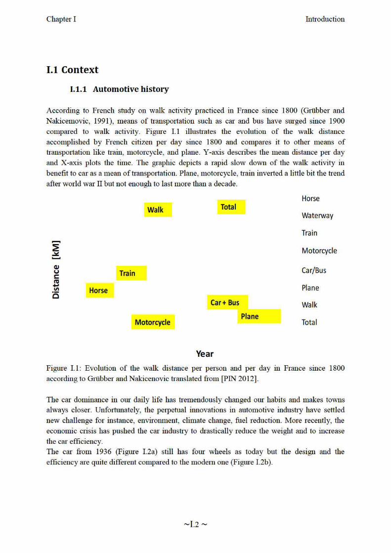
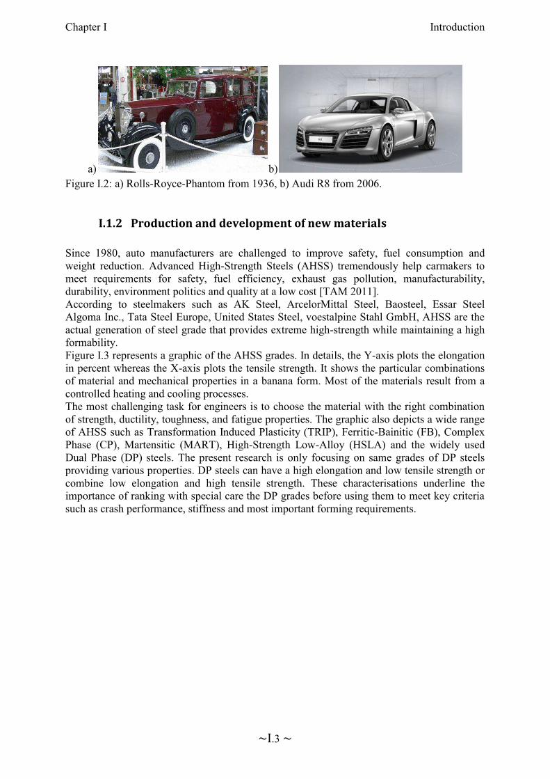
a) b)Figure I.2: a) Rolls-Royce-Phantom from 1936, b) Audi R8 from 2006.
I.1.2 Production and development of new materials
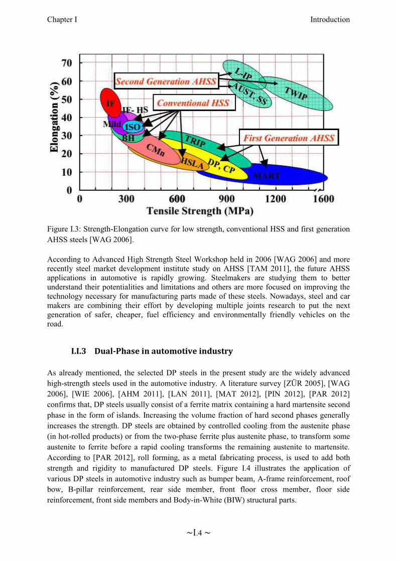
Since 1980, auto manufacturers are challenged to improve safety, fuel consumption and weight reduction. Advanced High-Strength Steels (AHSS) tremendously help carmakers to meet requirements for safety, fuel efficiency, exhaust gas pollution, manufacturability, durability, environment politics and quality at a low cost [TAM 2011]. According to steelmakers such as AK Steel, ArcelorMittal Steel, Baosteel, Essar Steel Algoma Inc., Tata Steel Europe, United States Steel, voestalpine Stahl GmbH, AHSS are the actual generation of steel grade that provides extreme high-strength while maintaining a high formability. Figure I.3 represents a graphic of the AHSS grades. In details, the Y-axis plots the elongation in percent whereas the X-axis plots the tensile strength. It shows the particular combinations of material and mechanical properties in a banana form. Most of the materials result from a controlled heating and cooling processes. The most challenging task for engineers is to choose the material with the right combination of strength, ductility, toughness, and fatigue properties. The graphic also depicts a wide range of AHSS such as Transformation Induced Plasticity (TRIP), Ferritic-Bainitic (FB), Complex Phase (CP), Martensitic (MART), High-Strength Low-Alloy (HSLA) and the widely used Dual Phase (DP) steels. The present research is only focusing on same grades of DP steels providing various properties. DP steels can have a high elongation and low tensile strength or combine low elongation and high tensile strength. These characterisations underline theimportance of ranking with special care the DP grades before using them to meet key criteria such as crash performance, stiffness and most important forming requirements.
Chapter I Introduction
~I.4 ~
Figure I.3: Strength-Elongation curve for low strength, conventional HSS and first generation AHSS steels [WAG 2006].
According to Advanced High Strength Steel Workshop held in 2006 [WAG 2006] and more recently steel market development institute study on AHSS [TAM 2011], the future AHSS applications in automotive is rapidly growing. Steelmakers are studying them to better understand their potentialities and limitations and others are more focused on improving the technology necessary for manufacturing parts made of these steels. Nowadays, steel and car makers are combining their effort by developing multiple joints research to put the next generation of safer, cheaper, fuel efficiency and environmentally friendly vehicles on the road.
I.I.3 Dual-Phase in automotive industry
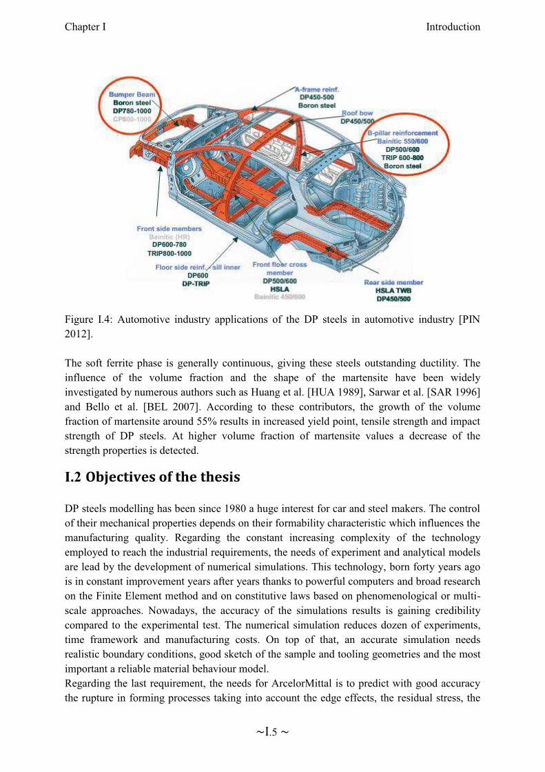
As already mentioned, the selected DP steels in the present study are the widely advanced high-strength steels used in the automotive industry. A literature survey [ZÜR 2005], [WAG 2006], [WIE 2006], [AHM 2011], [LAN 2011], [MAT 2012], [PIN 2012], [PAR 2012] confirms that, DP steels usually consist of a ferrite matrix containing a hard martensite second phase in the form of islands. Increasing the volume fraction of hard second phases generally increases the strength. DP steels are obtained by controlled cooling from the austenite phase (in hot-rolled products) or from the two-phase ferrite plus austenite phase, to transform some austenite to ferrite before a rapid cooling transforms the remaining austenite to martensite. According to [PAR 2012], roll forming, as a metal fabricating process, is used to add both strength and rigidity to manufactured DP steels. Figure I.4 illustrates the application of various DP steels in automotive industry such as bumper beam, A-frame reinforcement, roof bow, B-pillar reinforcement, rear side member, front floor cross member, floor side reinforcement, front side members and Body-in-White (BIW) structural parts.
Chapter I Introduction
~I.5 ~
Figure I.4: Automotive industry applications of the DP steels in automotive industry [PIN2012].
The soft ferrite phase is generally continuous, giving these steels outstanding ductility. The influence of the volume fraction and the shape of the martensite have been widely investigated by numerous authors such as Huang et al. [HUA 1989], Sarwar et al. [SAR 1996]and Bello et al. [BEL 2007]. According to these contributors, the growth of the volume fraction of martensite around 55% results in increased yield point, tensile strength and impact strength of DP steels. At higher volume fraction of martensite values a decrease of the strength properties is detected.
I.2 Objectives of the thesis
DP steels modelling has been since 1980 a huge interest for car and steel makers. The control of their mechanical properties depends on their formability characteristic which influences the manufacturing quality. Regarding the constant increasing complexity of the technology employed to reach the industrial requirements, the needs of experiment and analytical models are lead by the development of numerical simulations. This technology, born forty years ago is in constant improvement years after years thanks to powerful computers and broad research on the Finite Element method and on constitutive laws based on phenomenological or multi-scale approaches. Nowadays, the accuracy of the simulations results is gaining credibility compared to the experimental test. The numerical simulation reduces dozen of experiments, time framework and manufacturing costs. On top of that, an accurate simulation needs realistic boundary conditions, good sketch of the sample and tooling geometries and the most important a reliable material behaviour model. Regarding the last requirement, the needs for ArcelorMittal is to predict with good accuracy the rupture in forming processes taking into account the edge effects, the residual stress, the
Chapter I Introduction
~I.6 ~
material and mechanical anisotropy. Therefore a study has been carried out in 2008 by a joint research composed of MS²F Argenco (Liège, Belgium) and ArcelorMittal-Maizières (Maizières-Lès-Metz, France) targeting the development of a formability criterion for deep drawing, rolling, bending etc... As a result of this research study conducted by Ben Bettaieb for 2 years, an extended Gurson-Tvergaad-Needleman (GTN) model [BEN 2010] has been proposed for ductile failure. The study included a literature review and state of the art of formability criteria [BEN 2011], the development of a 3D advanced GTN Formability criterion (damage modelling) [BEN 2012] implemented in the finite element code Lagamine [ZHU 1992]. The Gurson-Tvergaard-Needleman-Ben-Bettaieb model (GTNB) takes into account the void nucleation. It allows for the accurate modelling of the observations of damage initiation and growth in DP steels measured by high-resolution X-ray absorption tomography [BOU 2008]. The numerical implementation used an explicit-implicit algorithm. It is explicit for the porosity state variables and implicit for other variables (macroscopic plastic strain and the yield stress of the dense matrix, backstress, equivalent plastic strain). This choice, justified by the complexity of the porosity function and dependency of the other variables, requires small time steps to avoid any convergence problem during the computation. The success of the GTNB model application on smooth specimen motivates the joint research to stretch the model out and to implement it into a commercial finite element code used by ArcelorMittal, through a three years PhD work. At the starting point of the present research, further X-ray tomography measurements have been investigated by Landron et al. [LAN 2011] on in situ tensile notched specimens made of DP steels. The experiments revealed a strong dependency between the density of voids, the back stress, and the triaxiality for these grades. Motivated by these new experimental observations and the industrial needs, the extension of the GTNB model has been developed in cooperation with four research teams (ArcelorMittal-Maizières, INSA-Lyon, ENSAM ParisTech-Metz and University of Liège) [FAN 2013].
The main goal of this work is to correlate the experimental results on notched samples and the model predictions for better understanding of the DP steel ductile fracture. To attempt this aim, the GTNB model has been adapted as "User-defined Material model subroutine" (VUMAT) in the Abaqus/explicit FE code [ABA 2011]. The model has been enriched by adding a coalescence model, a recent void nucleation and growth laws integrating the back stress variable [LAN 2011] and a fracture initiation criterion. These enhancements have been done based on high resolution X-ray tomography observations and measurements. In order to accurately correlate the finite element predictions with the experiments, a precise post-processing method has been developed taking into account identical results extraction between experiments and simulations. The numerical void volume fraction definition is the same as the one used in the test related to the number of cavities and their size in a fixed volume. Along with the attempt of integrating the back stress variable in the new nucleation law, a discussion has been opened regarding the triaxiality definition. The second objective is to be able to rank the DP steel grades chosen in this study. Finally, the experimental validation is being further extended to other sample geometries in flat sheet steels, as well as industrial application such as cross-die drawing test.

Chapter I Introduction
~I.7 ~
I.3 Contents
The aim of the second chapter is to give a general presentation of the Dual-Phase (DP) steels. It will show typical DP steels microstructures, mechanical properties and formability characteristics. The third chapter presents how the mechanical behaviour of DP steels can be predicted by plasticity, damage or fracture modelling. The experiments carried out on in-situ tensile notched axisymmetric specimens of DP steels [LAN 2011] revealed a strong dependency between the density of voids, the back stress, and the triaxiality. The fourth chapter summarizes the contributions brought to the damage and fracture modeling during this thesis. These contributions are based on the recent experimental results of [LAN 2011] on in-situ tensile notched axisymmetric specimens of DP steels, and the one-dimensional metallurgical models inferred therein. These contributions concern the void nucleation and void growth law, the coalescence model and an additional fracture initiation criterion, which were extended to the 3D incremental case and integrated in the proposed model (further called GTNBF). The parameter identification of the whole set of parameters of the GTNBF model for three DP steels is described in chapter five. Chapter six deals with the finite element implementation of proposed model in the commercial code Abaqus/Explicit. The implementation follows the path previously adopted by Ben Bettaieb [BEN 2012] in the finite element code Lagamine. The proposed implementation remains compatible with the two finite element codes, with the Abaqus routine “VUMAT” being used as an interface. The developed algorithm and code is
numerically validated. The potentialities and limitations of the model are contained in Chapter seven where the material parameters sensitivity is carefully checked. In front of that, the post processing and the element size influence on the current model are carried out. Chapter eight illustrates the industrial applications of the GTNBF model. Finally, the conclusions are summarized in chapter nine along with some potential future work.

Chapter II. Dual-Phase steels
Contents
Chapter II. Dual-Phase steels ............................................................................ II.1
II.1 Description of DP steels .......................................................................... II.2
II.1.1 Microstructures............................................................................... II.2
II.1.2 Mechanical properties .................................................................... II.3
II.I.3 Formability characteristics ............................................................. II.5
II.2 Experimental Damage Investigation of DP steels .................................. II.7
II.2.1 Experimental techniques to study fracture ..................................... II.7
II.2.2 X-ray tomography principle ........................................................... II.8
II.2.3 In-situ tensile tests .......................................................................... II.9
II.3 Selected DP steels grades ...................................................................... II.10
Chapter II Dual-Phase steels
~II.2 ~
The aim of the current chapter is to give a general presentation of the Dual-Phase (DP) steels. The first part presents the typical properties of DP steels: microstructures, mechanical properties and formability characteristics. The second part of the chapter focuses on the experimental damage tests realized to evaluate the void evolution in DP steels, and gives more details of the DP steels studied.
II.1 Description of DP steels
II.1.1 Microstructures
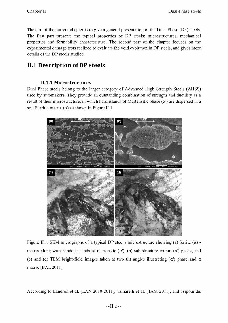
Dual Phase steels belong to the larger category of Advanced High Strength Steels (AHSS) used by automakers. They provide an outstanding combination of strength and ductility as a result of their microstructure, in which hard islands of Martensitic phase (α') are dispersed in a
soft Ferritic matrix (α) as shown in Figure II.1.
Figure II.1: SEM micrographs of a typical DP steel's microstructure showing (a) ferrite (α) -
matrix along with banded islands of martensite (α'), (b) sub-structure within (α') phase, and
(c) and (d) TEM bright-field images taken at two tilt angles illustrating (α') phase and α
matrix [BAL 2011].
According to Landron et al. [LAN 2010-2011], Tamarelli et al. [TAM 2011], and Tsipouridis
Chapter II Dual-Phase steels
~II.3 ~
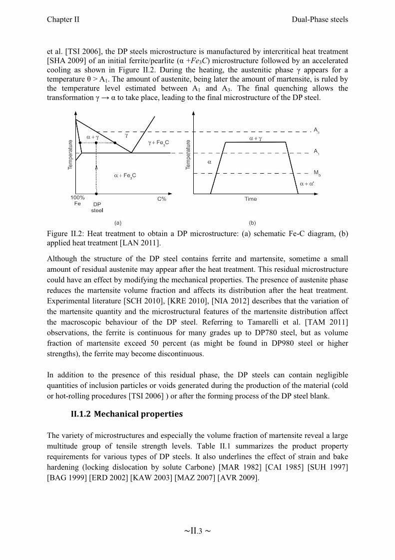
et al. [TSI 2006], the DP steels microstructure is manufactured by intercritical heat treatment [SHA 2009] of an initial ferrite/pearlite (α +Fe3C) microstructure followed by an accelerated cooling as shown in Figure II.2. During the heating, the austenitic phase γ appears for a
temperature θ > A1. The amount of austenite, being later the amount of martensite, is ruled by the temperature level estimated between A1 and A3. The final quenching allows the transformation γ → α to take place, leading to the final microstructure of the DP steel.
Figure II.2: Heat treatment to obtain a DP microstructure: (a) schematic Fe-C diagram, (b) applied heat treatment [LAN 2011].
Although the structure of the DP steel contains ferrite and martensite, sometime a small amount of residual austenite may appear after the heat treatment. This residual microstructure could have an effect by modifying the mechanical properties. The presence of austenite phase reduces the martensite volume fraction and affects its distribution after the heat treatment. Experimental literature [SCH 2010], [KRE 2010], [NIA 2012] describes that the variation of the martensite quantity and the microstructural features of the martensite distribution affect the macroscopic behaviour of the DP steel. Referring to Tamarelli et al. [TAM 2011]observations, the ferrite is continuous for many grades up to DP780 steel, but as volume fraction of martensite exceed 50 percent (as might be found in DP980 steel or higher strengths), the ferrite may become discontinuous.
In addition to the presence of this residual phase, the DP steels can contain negligible quantities of inclusion particles or voids generated during the production of the material (cold or hot-rolling procedures [TSI 2006] ) or after the forming process of the DP steel blank.
II.1.2 Mechanical properties
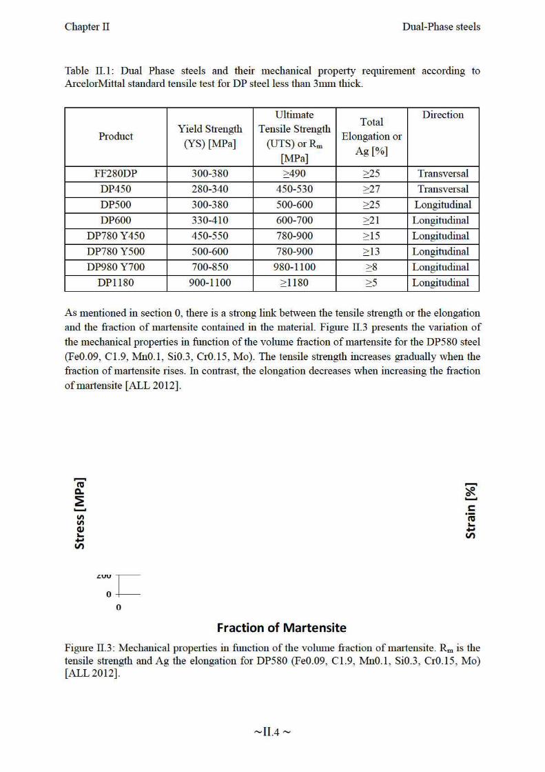
The variety of microstructures and especially the volume fraction of martensite reveal a large multitude group of tensile strength levels. Table II.1 summarizes the product property requirements for various types of DP steels. It also underlines the effect of strain and bake hardening (locking dislocation by solute Carbone) [MAR 1982] [CAI 1985] [SUH 1997] [BAG 1999] [ERD 2002] [KAW 2003] [MAZ 2007] [AVR 2009].

Chapter II Dual-Phase steels
~II.5 ~
II.I.3 Formability characteristics
The Dual-Phase steels present an excellent candidate for the car body structural components. These are often produced for safety-critical parts (see Figure II.4) which maintain passenger surviving space in crash events. The DP steels present a good balance of strength, formability, energy absorption and durability. Also the employability of this kind of steel provides the possibility of reducing the weight of the vehicle. DP is sometimes selected for visible body parts and closures, such as doors, hoods, front and rear rails. Other well known applications include: beams and cross members; rocker, sill, and pillar reinforcements; cowl inner and outer; crush cans; shock towers, fasteners, and wheels [TAM 2011].
Figure II.4: DP steels used for safety-critical body parts (General Motors, [BUI 2011]).
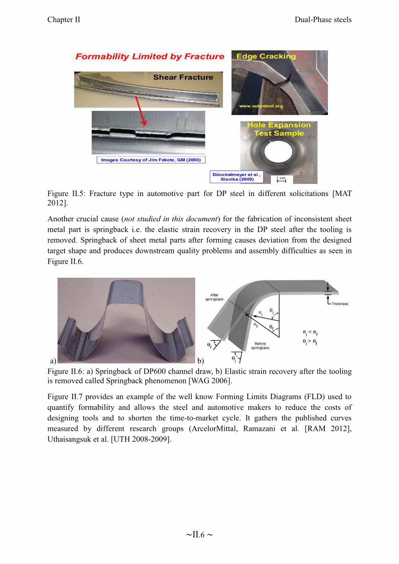
However, the excellent structural properties of this AHSS group are limited by the fracture phenomena. Fractures are different from ordinary steel and depend strongly on the DP steel grades used. The Figure II.5 below shows a shear fracture, an edge cracking and a crack during a hole expansion test. Numerous factors can affect the outstanding DP properties such as number of forming stages, tool geometry for each stage, boundary constraints, lubrication conditions, material variability and eventually the product changes [KEE 2009].
Chapter II Dual-Phase steels
~II.6 ~
Figure II.5: Fracture type in automotive part for DP steel in different solicitations [MAT 2012].
Another crucial cause (not studied in this document) for the fabrication of inconsistent sheet metal part is springback i.e. the elastic strain recovery in the DP steel after the tooling is removed. Springback of sheet metal parts after forming causes deviation from the designed target shape and produces downstream quality problems and assembly difficulties as seen in Figure II.6.
a) b)Figure II.6: a) Springback of DP600 channel draw, b) Elastic strain recovery after the tooling is removed called Springback phenomenon [WAG 2006].
Figure II.7 provides an example of the well know Forming Limits Diagrams (FLD) used to quantify formability and allows the steel and automotive makers to reduce the costs of designing tools and to shorten the time-to-market cycle. It gathers the published curves measured by different research groups (ArcelorMittal, Ramazani et al. [RAM 2012], Uthaisangsuk et al. [UTH 2008-2009].

Chapter II Dual-Phase steels
~II.8 ~
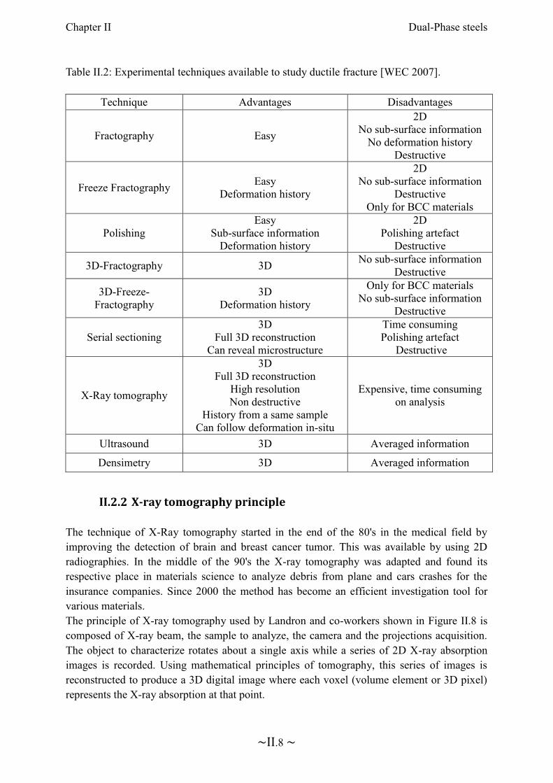
Table II.2: Experimental techniques available to study ductile fracture [WEC 2007].
II.2.2 X-ray tomography principle
The technique of X-Ray tomography started in the end of the 80's in the medical field by improving the detection of brain and breast cancer tumor. This was available by using 2D radiographies. In the middle of the 90's the X-ray tomography was adapted and found its respective place in materials science to analyze debris from plane and cars crashes for the insurance companies. Since 2000 the method has become an efficient investigation tool for various materials. The principle of X-ray tomography used by Landron and co-workers shown in Figure II.8 is composed of X-ray beam, the sample to analyze, the camera and the projections acquisition. The object to characterize rotates about a single axis while a series of 2D X-ray absorption images is recorded. Using mathematical principles of tomography, this series of images is reconstructed to produce a 3D digital image where each voxel (volume element or 3D pixel) represents the X-ray absorption at that point.
Technique Advantages Disadvantages
Fractography Easy
2DNo sub-surface information
No deformation historyDestructive
Freeze FractographyEasy
Deformation history
2DNo sub-surface information
DestructiveOnly for BCC materials
PolishingEasy
Sub-surface informationDeformation history
2DPolishing artefact
Destructive
3D-Fractography 3DNo sub-surface information
Destructive
3D-Freeze-Fractography
3DDeformation history
Only for BCC materialsNo sub-surface information
Destructive
Serial sectioning3D
Full 3D reconstructionCan reveal microstructure
Time consumingPolishing artefact
Destructive
X-Ray tomography
3DFull 3D reconstruction
High resolutionNon destructive
History from a same sampleCan follow deformation in-situ
Expensive, time consuming on analysis
Ultrasound 3D Averaged information
Densimetry 3D Averaged information
Chapter II Dual-Phase steels
~II.9 ~
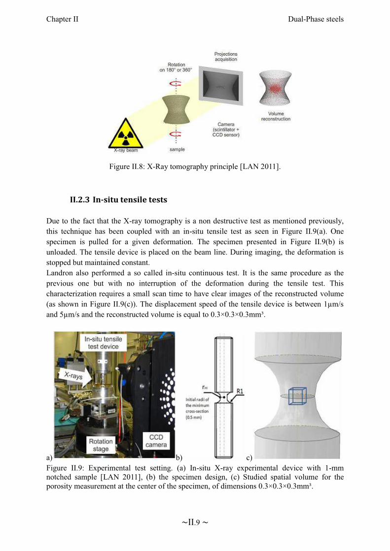
Figure II.8: X-Ray tomography principle [LAN 2011].
II.2.3 In-situ tensile tests
Due to the fact that the X-ray tomography is a non destructive test as mentioned previously, this technique has been coupled with an in-situ tensile test as seen in Figure II.9(a). One specimen is pulled for a given deformation. The specimen presented in Figure II.9(b) is unloaded. The tensile device is placed on the beam line. During imaging, the deformation is stopped but maintained constant. Landron also performed a so called in-situ continuous test. It is the same procedure as the previous one but with no interruption of the deformation during the tensile test. This characterization requires a small scan time to have clear images of the reconstructed volume (as shown in Figure II.9(c)). The displacement speed of the tensile device is between 1µm/s and 5µm/s and the reconstructed volume is equal to 0.3×0.3×0.3mm³.
a) b) c)Figure II.9: Experimental test setting. (a) In-situ X-ray experimental device with 1-mmnotched sample [LAN 2011], (b) the specimen design, (c) Studied spatial volume for the porosity measurement at the center of the specimen, of dimensions 0.3×0.3×0.3mm³.
b)
Chapter II Dual-Phase steels
~II.11 ~
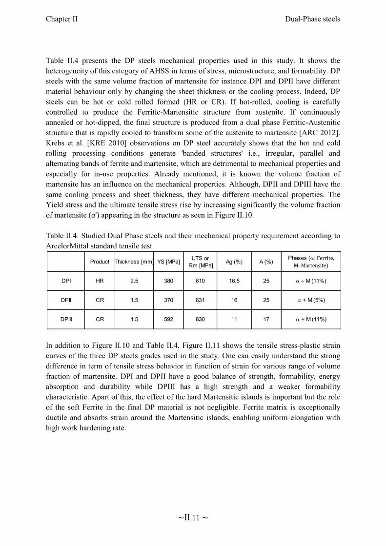
Table II.4 presents the DP steels mechanical properties used in this study. It shows the heterogeneity of this category of AHSS in terms of stress, microstructure, and formability. DP steels with the same volume fraction of martensite for instance DPI and DPII have different material behaviour only by changing the sheet thickness or the cooling process. Indeed, DP steels can be hot or cold rolled formed (HR or CR). If hot-rolled, cooling is carefully controlled to produce the Ferritic-Martensitic structure from austenite. If continuously annealed or hot-dipped, the final structure is produced from a dual phase Ferritic-Austenitic structure that is rapidly cooled to transform some of the austenite to martensite [ARC 2012]. Krebs et al. [KRE 2010] observations on DP steel accurately shows that the hot and cold rolling processing conditions generate 'banded structures' i.e., irregular, parallel and alternating bands of ferrite and martensite, which are detrimental to mechanical properties and especially for in-use properties. Already mentioned, it is known the volume fraction of martensite has an influence on the mechanical properties. Although, DPII and DPIII have the same cooling process and sheet thickness, they have different mechanical properties. The Yield stress and the ultimate tensile stress rise by increasing significantly the volume fraction of martensite (α') appearing in the structure as seen in Figure II.10.
Table II.4: Studied Dual Phase steels and their mechanical property requirement according to ArcelorMittal standard tensile test.
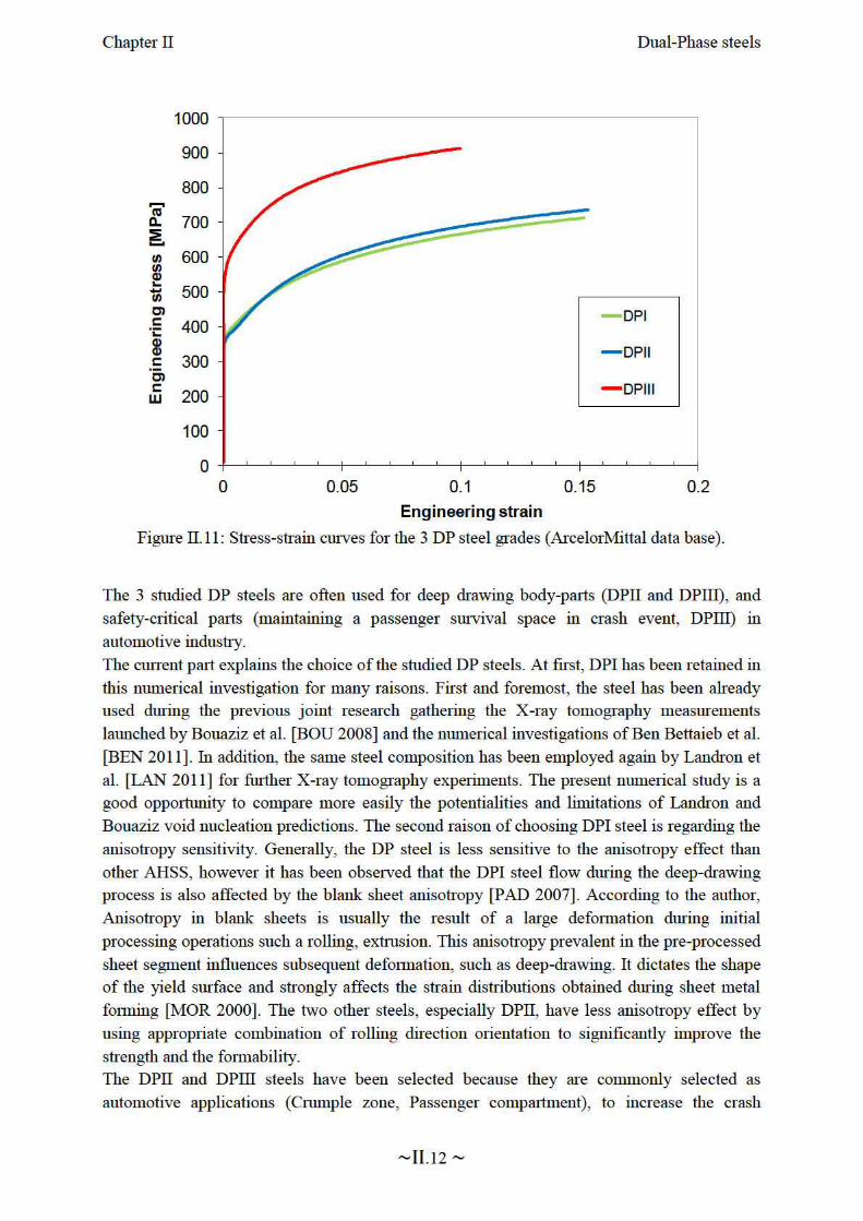
In addition to Figure II.10 and Table II.4, Figure II.11 shows the tensile stress-plastic strain curves of the three DP steels grades used in the study. One can easily understand the strong difference in term of tensile stress behavior in function of strain for various range of volume fraction of martensite. DPI and DPII have a good balance of strength, formability, energy absorption and durability while DPIII has a high strength and a weaker formability characteristic. Apart of this, the effect of the hard Martensitic islands is important but the role of the soft Ferrite in the final DP material is not negligible. Ferrite matrix is exceptionally ductile and absorbs strain around the Martensitic islands, enabling uniform elongation with high work hardening rate.
Product Thickness [mm] YS [MPa]UTS or
Rm [MPa]Ag (%) A (%)
Phases (a: Ferrite,
M: Martensite)
631
830
16
DPI
DPII
DPIII
HR 2.5 380 610
CR
CR
1.5
1.5
370
592 11
25
17
a + M (5%)
a + M (11%)
a + M (11%)16.5 25
Chapter II Dual-Phase steels
~II.13 ~
performance and protect the passenger by absorbing the low and high-speed vehicle deformation over a specific distance. Beyond the safety requirement, DPI and DPIII steels give the opportunity to compare the plasticity and the damage mechanisms provided by the hot and cold rolled forming process.

Chapter III. State of the art
Contents
Chapter III. State of the art ............................................................................... III.1
III.1 Introduction ........................................................................................... III.2
III.2 Plasticity modeling ............................................................................... III.3
III.2.1 Yield functions ............................................................................. III.3
III.2.2 Hardening functions ..................................................................... III.9
III.3 Damage modeling ............................................................................... III.15
III.3.1 Ductile damage mechanism........................................................ III.16
III.3.2 The Gurson model and its extensions ........................................ III.28
III.4 Fracture modeling ............................................................................... III.34
III.4.1 Micromechanical fracture criteria .............................................. III.34
III.4.2 Empirical fracture criteria .......................................................... III.35
III.5 Conclusions ......................................................................................... III.37

Chapter III State of the art
~III.2 ~
III.1 Introduction
The previous chapter presented the DP steels as the coexistence of hard islands of Martensitic phase dispersed in a soft Ferritic matrix. This microstructure provides a good combination of strength and ductility. The mechanical behaviour until failure has been studied for more than four decades. Nowadays, the ductile failure mechanism is well known and divided in three steps before fracture: void nucleation, void growth, and void coalescence. Chapter III describes the different proposals that the scientific community has developed to model the mechanical behavior of metals such as elasto-plastic damage constitutive laws as well as rupture criteria. Of course as often as possible, examples will be dedicated to DP steels.
Many researchers have contributed to give a proper microscopic approach. Habraken [HAB 2004] presents general features of crystal plasticity models and homogenization techniques to reach macroscopic scale while [KAD 2011], [VAJ 2012], [CHO 2013] are studying specifically DP models at microscopic or macroscopic scales. Very often macro scale is the world of phenomenological approaches which can however have roots within micro scale. The mechanical behaviour of DP steels can be modeled, based on elasto-plastic theory including both scales.
The phenomenological approach of elasto-plastic behaviour will be used within this thesis. It can mainly be defined by three different assumptions: a yield function, a hardening model and a plastic flow rule. The first hypothesis is described by an initial yield surface defined in stress space. This function also called plastic yield criterion is a mathematical description of the initial yield surface. It can be isotropic (von Mises [MIS 1928], Tresca [TRE 1868]) or anisotropic (Hill48 [HIL 1948], Barlat [BAR 2004]).The second hypothesis known as hardening model describes the evolution of the shape, the size and the position of the yield surface during the deformation. It is mainly divided in two categories: isotropic and kinematic hardening. The isotropic hardening models the expansion of the yield surface with no shape distortion while the kinematic hardening also called anisotropic hardening computes the yield surface displacement in the stress space. Shape distortion is only seldom addressed with phenomenological models. The third hypothesis called the flow rule defines the relation between the plastic strain rate tensor and the stress tensor. A plasticity model is called associative, if the yield function is considered as a plastic potential and its derivative provides the strain rate direction.
In the microscopic approach, not studied within this thesis, the global macroscopic stress and strain tensors are calculated relying on a numerical simulation of each particle or grain of the DP steels [KAD 2011], [VAJ 2012], [CHO 2013]. This approach physically describes the heterogeneity of plastic strain contained in the material. However, it requires a huge quantity of data storage and CPU time. Both approaches are complementary, the microscopic approach

Chapter III State of the art
~III.3 ~
allows understanding the mechanical plastic deformation and validating the phenomenological approach.
Section III.2 presents how the mechanical behaviour of DP steels can be predicted with the plasticity theory. Attention will be devoted to explain the isotropic and anisotropic yield functions as well as the hardening models. Section III.3 describes the coupled damage modeling concept where mechanical behavior is affected by the damage growth due to loading. The specific case of DP steels will be investigated. Within this section, both ductile damage mechanisms and some damage models are unveiled. Preceding the conclusion, the last section is dedicated to the fracture criteria or uncoupled damage approach applied on the DP steels.
III.2 Plasticity modeling
III.2.1 Yield functions
The Dual-Phase steel deforms elastically. During a monotonic loading it suddenly yields. In the plastic strain domain, the flow stress first increases due to hardening then eventually, it may soften due to damage. In numerous mechanical books [LEM 1988], [HOS 2005], [ROE 2006], the yield function defines the transition between elastic and plastic behaviour under complex stress states. According to Lemaitre and Chaboche [LEM 1988], the first scientific work on plasticity modeling began in 1868 with Tresca work on the maximum shear stress criterion [TRE 1868]. The goal of this section is to define the yield function with its associative normality rule. It briefly summarizes the most commonly isotropic and anisotropic yield functions that can be used to model the plastic behaviour of the DP steels.
III.2.1.1 Yield function and the associative normality rule
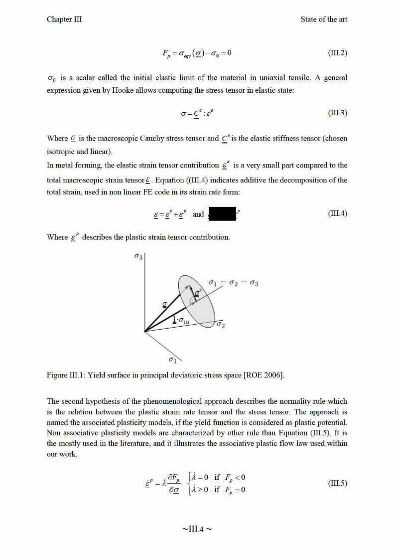
The yield surface or plastic yield criterion defined in the stress space as seen Figure III.1,models the elastic limit and the beginning of the plastic flow. It is written as:
( ) , 0p eqv y pF Fs s s= - £ (III.1)
Where ( )eqvs s is the equivalent stress and ys is the material flow stress. On one hand, when
( )eqvs s is smaller than ys ( )0pF < , the deformation is purely elastic.
On the other hand when ( )eqvs s is equal to ys ( )0pF = , the border is reached and the DP
steel starts to plastically deform. At initial state and before hardening function takes place, the yield surface is written as following:

Chapter III State of the art
~III.5 ~
Where ll is the plastic multiplier.
Figure III.2 shows that there are dozens of yield functions or plastic criteria usable for DP steels in metal forming processes, generally split in two families: the isotropic (von Mises, Tresca…) and the anisotropic (Hill, Barlat…) yield functions.
Figure III.2: Historical overview of different yield criteria [LIE 2009].
III.2.1.2 Isotropic yield functions The isotropic yield functions must not depend on the orientation of the load. The yield function
pF is based on the deviatoric stress tensor invariants. Figure III.2 shows an overview
of the most used isotropic yield criteria.
The von Mises yield criterion
The von Mises criterion [MIS 1928], known as the maximum distortion energy criterion, octahedral shear stress theory, or Maxwell-Huber-Hencky-von Mises theory, states that the plasticity is isotropic. The equation for the von Mises yield function is:
( ) ( )3:
2p eqv y yF s s s s s s¢ ¢
= - = - (III.6)
Where ¢s is the deviatoric stress tensor: ( )Itr sss
3
1-=
¢ with I second order unit tensor.
Consequently, the corresponding equivalent plastic strain rate p
eqve p
eqve can be given by the
explicit expression:


ERROR: undefinedresourceOFFENDING COMMAND: findresource
STACK:
/49 /CSA /49


![Widmung [Op.25 No.1] - Free-scores.com...Title Widmung [Op.25 No.1] Author Schumann, Robert - Arranger: Auer, Leopold - Publisher: Vienna: Universal Edition, 1920. Plate U.E. 6790](https://img.pdfslide.net/doc/110x75/6122a946a2c74f3e3b2cec77/widmung-op25-no1-free-title-widmung-op25-no1-author-schumann-robert.jpg)