Embed Size (px)
Citation preview
DDMC802
Multipurpose Modular Controller
RJ12 x274 mm(2.91 in)
95
mm
(3
.74
in)
105
mm
(4
.13 in
)
216 mm (8.50 in)
145 mm(1.77 in)
45 mm(1.77 in)
Installation Instructions
Instructions d’installation
Installationsanweisungen
Instrucciones de instalación
Istruzioni per l’installazione
Installatie-instructies
インストール手順安装指示
IEC Pollution Degree II
If ventilation is restricted,
apply load de-rating to
phase-cut modules.
Devices must be installed in an approved enclosure by a qualified electrician in accordance with all national and local electrical and construction codes and regulations.
Les appareils doivent être installés dans un lieu jugé apte, par un électricien qualifié et conformément aux règles et normes locales et nationales en matière d’électricité et de construction.
Die Geräte müssen von einem geprüften Elektriker entsprechend allen nationalen und lokalen Elektro – und Bauvorschriften in einem zugelassenen Gehäuse installiert werden.
Los dispositivos se deben instalar en un recinto aprobado por un electricista cualificado de acuerdo a todos los reglamentos eléctricos y de construcción locales y nacionales pertinentes
I dispositivi devono essere installati da un elettricista qualificato in un luogo approvato, in conformità a tutti gli standard e le norme nazionali e locali vigenti in materia di impianti elettrici e costruzioni edilizie.
Apparaten moeten door een erkende elektricien worden geïnstalleerd in een goedgekeurde behuizing in overeenstemming met alle nationale en lokale elektriciteits – en bouwvoorschriften en wetgeving.
デバイスを取り付ける際は、資格のある電気技師に依頼し、電気と建設に関する国および地域のすべての法令に従って、認可されている筐体内に取り付けてください。根据国家/地区及当地的电气与建筑规范和法规,该设备必须由有资质的电工安装在经批准的外罩内。
40° C (104° F)
0° C (32° F)
≤90%
www.lighting.philips.com/dynalite

2
≤ 16 A≤ 5 A/CH
DDMC802
≤ 5 mm2
10+ AWG0.6 Nm
5.5 Lb-in
•• L NDA+ DA-
CH3L N
DA+ DA-CH2
L NDA+SUPPLY DA-
CH1LN L N
DA+ DA-CH4
L NDA+ DA-
CH5L N
DA+ DA-CH6
L NDA+ DA-
CH7L N
DA+ DA-CH8
2
3
N/DA–LNCH1
L/DA+
+12
V
D +
D -
GN
DS
HLD
AU
XDyNet / RS-485 / DMX Rx
DRY CONTACT INPUTSRJ12
T 6.3 A M205C
1
N/DA–
CH2L/DA+ N/DA–
CH3L/DA+ N/DA–
CH4L/DA+ N/DA–
CH5L/DA+ N/DA–
CH6L/DA+ N/DA–
CH7 ManualOverrideL/DA+ N/DA–
CH8L/DA+
µP
1 100-240 V 16 A
SELV/CLASS 2
CLASS 1 or CLASS 2
12 V 200 mA
T 6.3 A M205C
2
T 6.3 A M205C
3
T 6.3 A M205C
4
1 CC C C2 3 4 5 6 7 8
4
DGBM2002 CHballast module
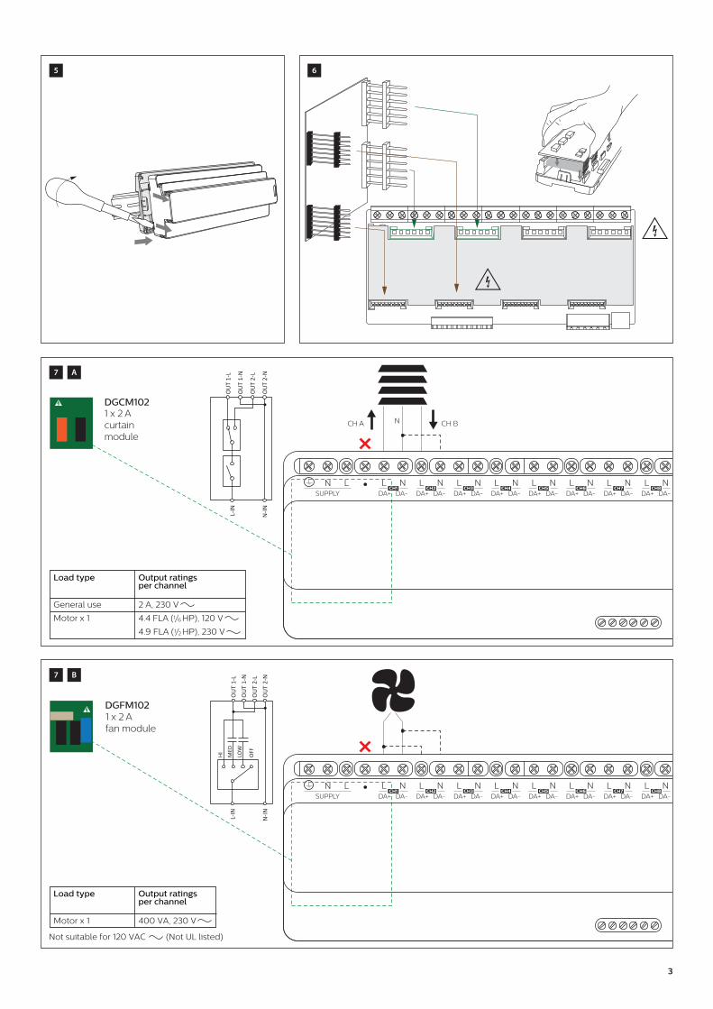
DGRM2042 x 4 Arelay module
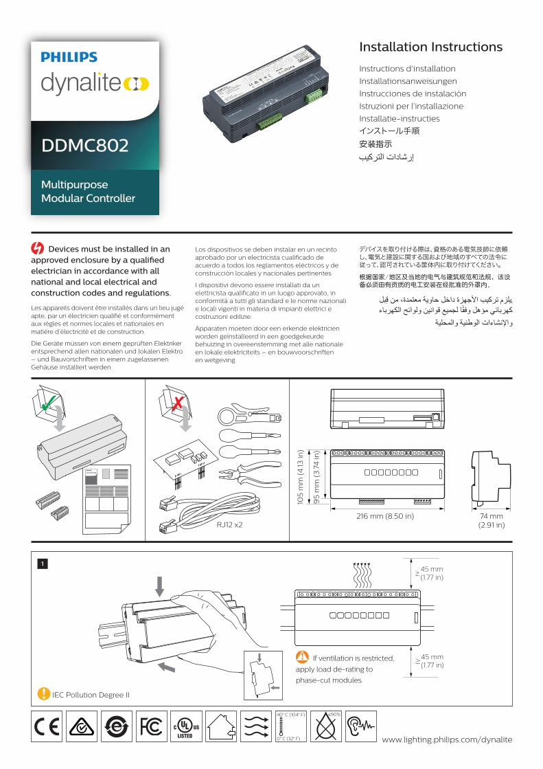
DGCM1021 x 2 Acurtain module
DGFM1021 x 2 Afan module
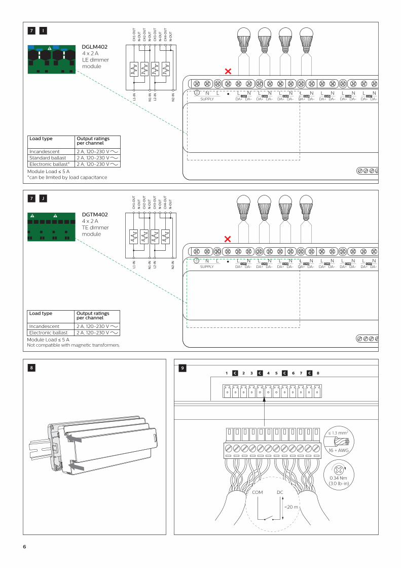
DGTM4024 x 2 ATrailing Edge dimmer module
DGLM4024 x 2 ALeading Edge dimmer module
DGLM1051 x 5 ALeading Edge dimmer module
DGLM2022 x 2 ALeading Edge dimmer module
DGTM1041 x 4 ATrailing Edge dimmer module
DGTM2022 x 2 ATrailing Edge dimmer module
IEC Overvoltage Category III
3
Load type Output ratings per channel
General use
Motor x 1
2 A, 230 V
4.4 FLA (1/6 HP), 120 V
4.9 FLA (1/2 HP), 230 V
NCH A CH B
DGCM1021 x 2 Acurtain module
L-IN
N-IN
OU
T 2-
N
OU
T 1-
L
OU
T 1-
N
OU
T 2-
L
•• L NDA+ DA-
CH3L N
DA+ DA-CH2
L NDA+SUPPLY DA-
CH1LN L N
DA+ DA-CH4
L NDA+ DA-
CH5L N
DA+ DA-CH6
L NDA+ DA-
CH7L N
DA+ DA-CH8
DGFM1021 x 2 Afan module
HI MED
LOW
OFF
L-IN
N-IN
OU
T 1-
LO
UT
1-N
OU
T 2-
LO
UT
2-N
•• L NDA+ DA-
CH3L N
DA+ DA-CH2
L NDA+SUPPLY DA-
CH1LN L N
DA+ DA-CH4
L NDA+ DA-
CH5L N
DA+ DA-CH6
L NDA+ DA-
CH7L N
DA+ DA-CH8
Load type Output ratings per channel
Motor x 1 400 VA, 230 V
Not suitable for 120 VAC (Not UL listed)
65
7 A
7 B
4
DGTM1041 x 4 ATE dimmermodule
Not compatible with magnetic transformers.
OU
T1-L
OU
T1-N
OU
T2-L
OU
T2-N
L-IN
N-IN
Load type Output ratings per channel
Incandescent 4 A, 120-230 V
Electronic ballast 4 A, 120-230 V
•• L NDA+ DA-
CH3L N
DA+ DA-CH2
L NDA+SUPPLY DA-
CH1LN L N
DA+ DA-CH4
L NDA+ DA-
CH5L N
DA+ DA-CH6
L NDA+ DA-
CH7L N
DA+ DA-CH8
DGBM200
Protocol
2 CHballast module
N
L
A (CH1)1-10 V DSI/DALI 1-10 V DSI/DALI
B (CH2)
N
L
A B
OU
T1-D
A+O
UT1
-DA-
OU
T2-D
A+O
UT2
-DA-
DALI
/1-1
0V/D
SI
DALI
/1-1
0V/D
SI
Load type
Max ballasts
1-10 V 10
DSI/DALI 5
Output ratings per channel
10 mA sink/source
13 V 10 mA guaranteed, 250 mA max. DALI Insulation System: Basic Supporting Class 1 / Class 2 wiring
•• L NDA+ DA-
CH3L N
DA+ DA-CH2
L NDA+SUPPLY DA-
CH1LN L N
DA+ DA-CH4
L NDA+ DA-
CH5L N
DA+ DA-CH6
L NDA+ DA-
CH7L N
DA+ DA-CH8
DGRM2042 x 4 Arelay module
OU
T 1-
LO
UT
1-N
OU
T 2-
LO
UT
2-N
L-IN
N-IN •• L N
DA+ DA-CH3
L NDA+ DA-
CH2N
DA+SUPPLY DA-
LN L NDA+ DA-
CH4L N
DA+ DA-CH5
L NDA+ DA-
CH6L N
DA+ DA-CH7
L NDA+ DA-
CH8CH1L
Load type Output ratings per channel
General Use 4 A, 230 V
Incandescent 600 W, 120 V1100 W, 230 V
Standard ballast
4 A, 120 V3 A, 230 V
Electronic ballast
2 A, 120 V
Module Load ≤ 5 A
7 D
7 C
7 E

5
DGTM2022 x 2 ATE dimmer module
CH1-
OU
TN
-OU
TCH
2-O
UT
N-O
UT
L-IN
N-IN
Not compatible with magnetic transformers.
•• L NDA+ DA-
CH3L N
DA+ DA-CH2
L NDA+SUPPLY DA-
CH1LN L N
DA+ DA-CH4
L NDA+ DA-
CH5L N
DA+ DA-CH6
L NDA+ DA-
CH7L N
DA+ DA-CH8
Load type Output ratings per channel
Incandescent
Electronic ballast
2 A, 120-230 V
2 A, 120-230 V
DGLM1051 x 5 ALE dimmer module
CH1-
OU
TN
-OU
TCH
1-O
UT
N-O
UT
CH1-
OU
TN
-OU
TCH
1-O
UT
N-O
UT
Load type Output ratings per channel
Incandescent 5 A, 120-230 VStandard ballast 5 A, 120-230 VElectronic ballast*
*can be limited by load capacitance
5 A, 120-230 V
L1-IN
L2-IN
N1-
IN
N2-
IN •• L NDA+ DA-
CH3L N
DA+ DA-CH2
L NDA+SUPPLY DA-
CH1LN L N
DA+ DA-CH4
L NDA+ DA-
CH5L N
DA+ DA-CH6
L NDA+ DA-
CH7L N
DA+ DA-CH8
DGLM2022 x 2 ALE dimmer module
CH1-
OU
TN
-OU
TCH
2-O
UT
N-O
UT
L-IN
N-IN
Load type Output ratings per channel
Incandescent
Standard ballast
2 A, 120-230 V
2 A, 120-230 V
Electronic ballast* 2 A, 120-230 V
*can be limited by load capacitance.
•• L NDA+ DA-
CH3L N
DA+ DA-CH2
L NDA+SUPPLY DA-
CH1LN L N
DA+ DA-CH4
L NDA+ DA-
CH5L N
DA+ DA-CH6
L NDA+ DA-
CH7L N
DA+ DA-CH8
7
7 G
F
7 H
6
DGLM4024 x 2 ALE dimmer module
CH1-
OU
TN
-OU
TCH
2-O
UT
N-O
UT
L1-IN
L2-IN
N1-
IN
N2-
IN
CH3-
OU
TN
-OU
TCH
4-O
UT
N-O
UT
•• L NDA+ DA-
CH3L N
DA+ DA-CH2
L NDA+SUPPLY DA-
CH1LN L N
DA+ DA-CH4
L NDA+ DA-
CH5L N
DA+ DA-CH6
L NDA+ DA-
CH7L N
DA+ DA-CH8
*can be limited by load capacitanceModule Load ≤ 5 A
Load type Output ratings per channel
Incandescent 2 A, 120-230 VStandard ballast 2 A, 120-230 VElectronic ballast* 2 A, 120-230 V
UT
UT
UT
UT
CH1-
ON
-OU
TCH
2-O
N-O
UT
L1-IN
L2-IN
N1-
IN
N2-
IN
CH3-
ON
-OU
TCH
4-O
N-O
UT
DGTM4024 x 2 ATE dimmer module
Not compatible with magnetic transformers.
•• L NDA+ DA-
CH3L N
DA+ DA-CH2
L NDA+SUPPLY DA-
CH1LN L N
DA+ DA-CH4
L NDA+ DA-
CH5L N
DA+ DA-CH6
L NDA+ DA-
CH7L N
DA+ DA-CH8
Load type Output ratings per channel
Incandescent 2 A, 120-230 VElectronic ballast 2 A, 120-230 V
Module Load ≤ 5 A
1 C C C C2 3 4 5 6 7 8
COM DC
<20 m
≤ 1.3 mm2
16 + AWG
0.34 Nm (3.0 lb-in)
98
7 I
7 J

7
≤ 2.5 mm2
12 + AWG
0.4 Nm3.5 Lb-in
SH
LD
GN
D
D+
D-
+12
V
AU
X
DyNet RS-485
GND AUX
< 20 m
≤ 2 A
RJ12
DyNetRS-485
GNDGND
D+D–
+12 V+12 V
+12
V+1
2 V D-
D+
GN
DG
ND
DyNet RS-485
DMX 512
Rx
11
10 A
10 B
A
11 B
Philips Dynalitewww.lighting.philips.com/dynalite
© 2017 Philips Lighting. All rights reserved.
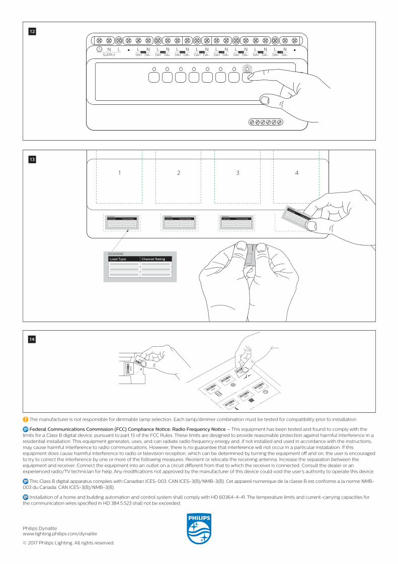
The manufacturer is not responsible for dimmable lamp selection. Each lamp/dimmer combination must be tested for compatibility prior to installation.
Federal Communications Commission (FCC) Compliance Notice: Radio Frequency Notice – This equipment has been tested and found to comply with the limits for a Class B digital device, pursuant to part 15 of the FCC Rules. These limits are designed to provide reasonable protection against harmful interference in a residential installation. This equipment generates, uses, and can radiate radio frequency energy and, if not installed and used in accordance with the instructions, may cause harmful interference to radio communications. However, there is no guarantee that interference will not occur in a particular installation. If this equipment does cause harmful interference to radio or television reception, which can be determined by turning the equipment off and on, the user is encouraged to try to correct the interference by one or more of the following measures: Reorient or relocate the receiving antenna. Increase the separation between the equipment and receiver. Connect the equipment into an outlet on a circuit different from that to which the receiver is connected. Consult the dealer or an experienced radio/TV technician for help. Any modifications not approved by the manufacturer of this device could void the user’s authority to operate this device.
This Class B digital apparatus complies with Canadian ICES-003: CAN ICES-3(B)/NMB-3(B). Cet appareil numerique de la classe B est conforme a la norme NMB-003 du Canada: CAN ICES-3(B)/NMB-3(B).
Installation of a home and building automation and control system shall comply with HD 60364-4-41. The temperature limits and current-carrying capacities for the communication wires specified in HD 384.5.523 shall not be exceeded.
1 2 3 4
DGXXXXX
Load Type Channel Rating
DGXXXXX
Load Type Channel Rating Load Type Channel Rating Load Type Channel Rating
DGXXXXXLoad Type
Channel Rating
DGXXXXX DGXXXXX
14
13
12
•• L NDA+ DA-
CH3L N
DA+ DA-CH2
L NDA+SUPPLY DA-
CH1LN L N
DA+ DA-CH4
L NDA+ DA-
CH5L N
DA+ DA-CH6
L NDA+ DA-
CH7L N
DA+ DA-CH8


![WELCOME [lightmoves.com.au]lightmoves.com.au/downloads/Dealer/Dealer...DR2PA SINGLE COLUMN REVOLUTION PANEL Mounted in 1 gang masonry back box (Box not by Philips) Station 0 DR2PA](https://img.pdfslide.net/doc/110x75/60ad9df3c753e77a42090ff2/welcome-dr2pa-single-column-revolution-panel-mounted-in-1-gang-masonry-back.jpg)