Embed Size (px)
Citation preview

DE Attachments
Design Examples
Attachment DE1: SDC A Design Flow Chart
o Flow chart for design of precast bent cap connections in SDC A
Attachment DE2: SDC A Design Example—Grouted Duct Connection
o Design example for grouted duct connection in SDC A (minimum joint reinforcement)
Attachment DE3: SDC A Design Example—Cap Pocket Connection
o Design example for cap pocket connection in SDC A (minimum joint reinforcement)
Attachment DE4: SDCs B, C, and D Design Flow Chart
o Flow chart for design of precast bent cap connections in SDCs B, C, and D
Attachment DE5: SDC B Design Example—Grouted Duct Connection
o Design example for grouted duct connection in SDC B (minimum joint reinforcement)
Attachment DE6: SDC B Design Example—Cap Pocket Connection
o Design example for cap pocket connection in SDC B (minimum joint reinforcement)
Attachment DE7: SDCs C and D Design Example—Grouted Duct Connection
o Design example for grouted duct connection in SDCs C and D (additional joint
reinforcement)
Attachment DE8: SDCs C and D Design Example—Cap Pocket Connection
o Design example for cap pocket connection in SDCs C and D (additional joint reinforcement)
Attachment DE9: SDCs C and D Design Example—Hybrid Connection
o Design example for hybrid connection in SDCs C and D
Attachment DE10: SDCs C and D Design Example—Integral Connection
o Design example for integral connection in SDCs C and D
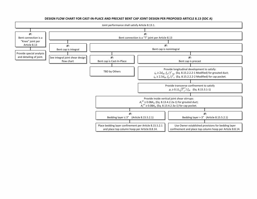
DESIGN FLOW CHART FOR CAST‐IN‐PLACE AND PRECAST BENT CAP JOINT DESIGN PER PROPOSED ARTICLE 8.13 (SDC A)
Joint performance shall satisfy Article 8.13.1.
TBD by Others
IF: Bent cap is Cast‐In‐Place
IF: Bedding layer ≤ 3” (Article 8.15.5.2.1)
IF: Bedding layer > 3” (Article 8.15.5.2.1)
Use Owner established provisions for bedding layer confinement and place top column hoop per Article 8.8.14.
Place bedding layer confinement per Article 8.15.5.2.1 and place top column hoop per Article 8.8.14.
Provide special analysis and detailing of joint.
IF: Bent connection is a “Knee” joint per Article 8.13
IF: Bent connection is a “T” joint per Article 8.13
IF: Bent cap is precast
Provide inside vertical joint shear stirrups: As
jvi ≥ 0.08Ast (Eq. 8.13.4.2.2a‐1) for grouted duct; As
jvi ≥ 0.08Ast (Eq. 8.13.4.2.3a‐1) for cap pocket.
IF: Bent cap is integral
See integral joint shear design flow chart
IF: Bent cap is nonintegral
Provide longitudinal development to satisfy: lac ≥ 2 ⁄ (Eq. 8.15.2.2.2‐1 Modified) for grouted duct;
lac ≥ 2.3 ⁄ (Eq. 8.15.2.2.2‐2 Modified) for cap pocket.
Provide transverse confinement to satisfy
ρs ≥ 0.11 ’ / fyh (Eq. 8.15.3.1‐1)

1 5
Grouted Duct Joint Design Example For SDC A
Geometry and Design Parametersf'c = 4.0 ksi (specified compressive strength of bent cap)f'ce = 1.3f'c = 5.2 ksi (expected f'c of bent cap)f'cg = 7.5 ksi (specified compressive strength of grout)
Check: f'cg ≥ max[1.25(f'ce+0.5)=7 ksi, 6 ksi)]OK per BCS 8.13.8.3.2a
fy = 60 ksi (yield stress of column bars)fyh = 60 ksi (yield stress of hoops)
SHEET NO PROJECT DESIGN EXAMPLES
PROJECT NO DESIGNED BY DATE OF
Note: 1. The provisions of 8.13.1 apply to all levels within SDC A, but where SD1 is less than 0.10, the designer has the option of using alternative precast bent cap connections such as those detailed in Matsumoto et al., 2001.
DATE
An SDC A grouted duct connection between a column and a precast bent cap is not expected to be subjected to significant seismic demand. Therefore, the joint stresses in the connection are not checked; however, limited joint shear reinforcement is required. This SDC A design example applies to a T‐joint of a rectangular, nonintegral precast bent cap supported by circular columns. The applicable commentary sections in the AASHTO Guide Specifications for LRFD Seismic Bridge Design (SGS) provide additional background.
M. STILLER 11/6/2009
CHECKED BY E. MATSUMOTO 11/9/2009
NCHRP 12‐74
CLIENT SACRAMENTO STATE UNIV.
AASHTO SEISMIC GUIDE SPECIFICATIONS NONINTEGRAL GROUTED DUCT BENT CAP JOINT DESIGN EXAMPLE ‐ SDC A
AASHTO Guide Specifications for LRFD Seismic Bridge Design (SGS)
AASHTO LRFD Construction Specifications (BCS)
SUBJECT
Ascaptop
ABent cap width = ft (Bcap)
Bent cap height ft (Ds)Stirrup bar size: #6
Column diameter = 4.0 ft (Dc)
Ast in2 (#10 Tot 20)
Hoop bar size: #6Hoop spacing = 4.0 in
Joint Performance SGS8.13.1
Joint Proportioning (Minimum Development Length) SGS8.13.2.2
lac ≥ 2dbl fy Eq. 8.15.2.2.2‐1(modified)
= 5.00
= 25.4
5.25
Capacity of the bent cap section needs to satisfy applicable load combinations, including the Strength load cases. The bent cap section capacity is not investigated in this design example.
Typical cap section within Dc from face of column. Note: Bent cap reinforcement shown reflects that required by load combinations before application of joint shear design requirements.
f'cg
Ascaptop
Ascapbot
Av
Bedding Layer

2 5SHEET NO PROJECT DESIGN EXAMPLES
PROJECT NO DESIGNED BY DATE OF
DATE M. STILLER 11/6/2009
CHECKED BY E. MATSUMOTO 11/9/2009
NCHRP 12‐74
CLIENT SACRAMENTO STATE UNIV.
AASHTO SEISMIC GUIDE SPECIFICATIONS NONINTEGRAL GROUTED DUCT BENT CAP JOINT DESIGN EXAMPLE ‐ SDC ASUBJECT
dbl = in (#10 rebar)fy = ksi (Article 8.13.2.2 permits use of fy instead of fye)f'cg = ksi = min (7.5 ksi, 7.0 ksi) per Article 8.15.2.2.2
lac = in (minimum)
Extend column reinforcement as far as practically possible; assume 3" clear from opposite face.
lac = Ds ‐ 3" = 5.0 ft x 12"/ft ‐ 3" = in
in ≥ in minimum OK Extend to top face of cap less 3 in cover.
Minimum Joint Reinforcing SGS8.13.3.2.1
Calculate required volumetric ratio of transverse joint reinforcement:
ρ ≥ 0 11 √f' / f ≥ 0 0037 Eq 8 15 3 1 1
57.0 21.8
1.27607.0
21.8
57.0
Transverse reinforcement in the form of hoops will be placed to encompass the ducts and thereby satisfy the minimum joint reinforcement requirement. The size and spacing of this reinforcement is determined by applying the provisions of Article 8.13.3.2.1 and Eq. 8.15.3.1‐1.
ρs ≥ 0.11 √f'c / fyh ≥ 0.0037 Eq. 8.15.3.1‐1
ρs ≥
ρs =
Asp = in2 (#6 hoop)D'gd = in (confined diameter of column between centroids of #6 hoop)s = in
D'gd =
D'gd = 48.0" ‐ 2" x 2 ‐ 0.88" ‐ 1.44" + 4" + 0.12" x 2 = in(deformed diameters are used for clearance calculations)
ρs =
ρs = ≥ minimum OK
Actual even spacing is 9.37 inches, total 6 hoops.
Column diameter ‐ clear cover x 2 ‐ hoop diameter ‐ long. column reinf diameter + grouted duct inside diameter + corrugation amplitude x 2.
0.0037
0.0038
0.003810" spacing is adequate (Note: Common practice is to carry hoop spacing from column into cap, or s=4" in this case.)
45.9210.0
45.92
(trial spacing of transverse reinforcement hoops, 12" or 0.3Ds maximum per Art. 8.13.3.2.1)
Assume transverse reinforcement in the joint is the same size as the column plastic hinging region transverse reinforcement.
0.44
0.004
4AspD'gd s
D'gd
Grouted DuctColumn Reinf.
Column
Hoop

3 5SHEET NO PROJECT DESIGN EXAMPLES
PROJECT NO DESIGNED BY DATE OF
DATE M. STILLER 11/6/2009
CHECKED BY E. MATSUMOTO 11/9/2009
NCHRP 12‐74
CLIENT SACRAMENTO STATE UNIV.
AASHTO SEISMIC GUIDE SPECIFICATIONS NONINTEGRAL GROUTED DUCT BENT CAP JOINT DESIGN EXAMPLE ‐ SDC ASUBJECT
Nonintegral Bent Cap Joint Shear Design SGS8.13.4
Vertical Stirrups Inside the Joint Region SGS8.13.4.2.2a
Asjvi ≥ 0.08 Ast Eq. 8.13.4.2.2a‐1
Ast = in2
Asjvi ≥ in2
Use #6 single U stirrups Tot 3 patterns placed evenly through joint
Asjvi = 3 patterns x 2 legs / pattern x 0.44 in2/ leg = in2 ≥ in2 OK
Note:
Bedding Layer Reinforcement SGS8.13.4.2.1
2.64 2.03
Three patterns are required and used. The minimum number of stirrups is two, per Article 8.13.4.2.2a, and the bar size is no smaller than what is used in the bent cap shear stirrups. If only two stirrups were required, three may be used to reduce the spacing between stirrups to satisfy temperature and shrinkage requirements for side faces of the bent cap per AASHTO LRFD Article 5.10.8.
2.03
25.40
Figures Showing Final Design
Elevation View at Column Connection
Provide bedding layer transverse reinforcement to match the size and type used in the column plastic hinging region (#6 bar). Hoop will be placed at mid‐height in the bedding layer; bedding layer to be 3" thick. Cover on top column hoop to be 2" as shown in figures below, and resulting center to center spacing of transverse reinforcement is 4" throughout, in accordance with Article 8.8.14.
#6 Stirrups, Tot 3
#6 Stirrups @ 8"
#10, Tot 16 Typ
#10, Tot 3 each face
#6 bedding hoop

4 5SHEET NO PROJECT DESIGN EXAMPLES
PROJECT NO DESIGNED BY DATE OF
DATE M. STILLER 11/6/2009
CHECKED BY E. MATSUMOTO 11/9/2009
NCHRP 12‐74
CLIENT SACRAMENTO STATE UNIV.
AASHTO SEISMIC GUIDE SPECIFICATIONS NONINTEGRAL GROUTED DUCT BENT CAP JOINT DESIGN EXAMPLE ‐ SDC ASUBJECT
#6 stirrups, Tot 3
See detail below
#6 hoops @ 4"
#10 Column Reinf
#10, Tot 12(6 bundles)
#6 hoops, Tot 6, even spacing
#10, Tot 12 (6 bundles)
5'‐3"
5'‐0"
4'‐0"
Bedding layer
Simplified Section at Column Edge
Typical Section through Joint
4" overall spacing maintained
Clear cover may be less than 2" per Art. 8.8.14 as required.
Bent Cap
Bedding
Layer
Column
1.5"
2.5"
per Art. 8.13.3.2.1
per Art. 8.8.14

5 5SHEET NO PROJECT DESIGN EXAMPLES
PROJECT NO DESIGNED BY DATE OF
DATE M. STILLER 11/6/2009
CHECKED BY E. MATSUMOTO 11/9/2009
NCHRP 12‐74
CLIENT SACRAMENTO STATE UNIV.
AASHTO SEISMIC GUIDE SPECIFICATIONS NONINTEGRAL GROUTED DUCT BENT CAP JOINT DESIGN EXAMPLE ‐ SDC ASUBJECT
Plan View at Column Connection
5'‐3"
Grouted Duct Column
#6 Hoops
#10 Tot 12(6 bundles)
#6 Stirrups, Tot 3#6 Stirrups @ 8" #6 Stirrups @ 8"
For additional details, see Figures 8.13.4.2.2‐1, 8.13.4.2.2‐2, and 8.13.4.2.2‐3 in the AASHTO Guide Specifications for LRFD Seismic Bridge Design.

1 6
Cap Pocket Joint Design Example For SDC A
Geometry and Design Parametersf'c = 4.0 ksi (specified compressive strength of bent cap)f'ce =1.3f'c = 5.2 ksi (expected f'c of bent cap)f'c_pocket: (specified compressive strength of pocket fill)Select cap pocket strength to satisfy BCS.f'c_pocket = 1.3 f'c + 0.5 ksi = 5.7 ksi (BCS 8.13.8.3.3a)f h (yield strength of equivalent hoop)
AASHTO LRFD Construction Specifications (BCS)
PROJECT NO 11/9/2009
11/6/2009
CLIENT DATE DATE
SUBJECT AASHTO SEISMIC GUIDE SPECIFICATIONS NONINTEGRAL CAP POCKET BENT CAP JOINT DESIGN EXAMPLE ‐ SDC A
AASHTO Guide Specifications for LRFD Seismic Bridge Design (SGS)
An SDC A cap pocket connection between a column and a precast bent cap is not expected to be subjected to significant seismic demand. Therefore, the joint stresses in the connection are not checked; however, limited joint shear reinforcement is required. This SDC A design example applies to a T‐joint of a rectangular, nonintegral precast bent cap supported by circular columns. The applicable commentary sections in the AASHTO Guide Specifications for LRFD Seismic Bridge Design (SGS) provide additional background.
Note: 1. The provisions of 8.13.1 apply to all levels within SDC A, but where SD1 is less than 0.10, the designer has the option of using alternative precast bent cap connections such as those detailed in Matsumoto et al., 2001.
OF SHEET NO PROJECT DESIGN EXAMPLES
NCHRP 12‐74
SACRAMENTO STATE UNIV.
DESIGNED BY M. STILLER
CHECKED BY E. MATSUMOTO
Ascaptopfyh (yield strength of equivalent hoop)fyp (nominal yield stress of steel pipe)θ (angle between horizontal axis of
cap and pipe helical corrugationor lock seam)
fy = 60 ksi (yield stress of column bars)
Bent cap width = ft (Bcap)
Bent cap height ft (Ds)Stirrup bar size: #6
Column diameter = 4.0 ft (Dc)
Ast in2 (#10 Tot 20)
Hoop bar size: #6Hoop spacing = 4.0 in
Joint Performance SGS8.13.1
Capacity of the bent cap section needs to satisfy applicable load combinations, including the Strength load cases. The bent cap section capacity is not investigated in this design example.
= 5.005.25
= 25.4Typical cap section within Dc from face of column. Note: Bent cap reinforcement shown reflects that required by load combinations before application of joint shear design requirements.
Ascaptop
Ascapbot
Av
Bedding Layer

2 6
PROJECT NO 11/9/2009
11/6/2009
CLIENT DATE DATE
SUBJECT AASHTO SEISMIC GUIDE SPECIFICATIONS NONINTEGRAL CAP POCKET BENT CAP JOINT DESIGN EXAMPLE ‐ SDC A
OF SHEET NO PROJECT DESIGN EXAMPLES
NCHRP 12‐74
SACRAMENTO STATE UNIV.
DESIGNED BY M. STILLER
CHECKED BY E. MATSUMOTO
Joint Proportioning (Minimum Development Length) SGS8.13.2.2
lac ≥ 2.3dbl fyEq. 8.15.2.2.2‐2
(modified)
dbl = in (#10 bar diameter)fy = ksi (Article 8.13.2.2 permits use of fy instead of fye)f'c = ksi (cap pocket concrete) = min (5.7 ksi, 7.0 ksi) per Article 8.15.2.2.2
lac = in (minimum)
Extend column reinforcement as far as practically possible, assume 3" clear from opposite face.
lac = Ds ‐ 3" = 5.0 ft x 12"/ft ‐ 3" = in
in ≥ in minimum OK Extend to top face of cap less 3 in cover.
Minimum Joint Reinforcing SGS8.13.3.2.2
5.7
57.0
57.0
30.7
30.7
Minimum thickness of the helical corrugated steel pipe confinement is determined from Eq. 8.15.3.2.2‐1 and Eq. 8.15.3.2.2‐2. This more involved calculation can be replaced by Eq. 8.13.3.2.2‐1,
60
f'c
1.27
Calculate required volumetric ratio of transverse joint reinforcement:
ρs ≥ 0.11 √f'c / fyh Eq. 8.15.3.1‐1
ρs ≥
SGS8.15.3.2.2
ρs = s =
Asp = in2 (assume #6 hoop to match column transverse reinforcement)D'cp = in (average confined dia. of column between corrugated steel pipe walls)ρs = (minimum volumetric ratio)
Corrugated steel pipe
D'cp
D'cp = Nominal inside diameter of corrugated pipe + average wall corrugation width.
s = in max spacingTherefore, the number of equivalent hoops per foot is 12" / s = hoops/ft
0.004
48.650.0037
9.91.216
0.44
8.15.3.2.2 1 and Eq. 8.15.3.2.2 2. This more involved calculation can be replaced by Eq. 8.13.3.2.2 1, a simplified equation that provides a more conservative wall thickness.
Use the minimum volumetric ratio to calculate the required number of equivalent #6 hoops per unit length of corrugated steel pipe. Use a unit length of 1 foot. Use a 48" ID corrugated pipe based on the outer diameter of column reinforcement pattern.
4AspD'cp s
4AspD'cp ρs

3 6
PROJECT NO 11/9/2009
11/6/2009
CLIENT DATE DATE
SUBJECT AASHTO SEISMIC GUIDE SPECIFICATIONS NONINTEGRAL CAP POCKET BENT CAP JOINT DESIGN EXAMPLE ‐ SDC A
OF SHEET NO PROJECT DESIGN EXAMPLES
NCHRP 12‐74
SACRAMENTO STATE UNIV.
DESIGNED BY M. STILLER
CHECKED BY E. MATSUMOTO
Calculate the nominal confining hoop force of the equivalent hoops.
FH = nh Asp fyh Eq. 8.15.3.2.2‐2
nh = ea (number of equivalent hoops per unit length)
Asp = in2 (area of #6 equivalent hoop)fyh = ksi (yield strength of equivalent hoop)
FH = kips/ft
tpipe ≥ max Eq. 8.15.3.2.2‐1
FH = kips/ftHp = in/ft (specified unit length)fyp = ksi (manufacturer specified)θ = deg (manufacturer specified)
32.11
32.112.030.020.0
1.216
0.4460.0
Calculate the thickness of the corrugated steel pipe that provides the same nominal confinement as standard hoop reinforcement.
FHHp fyp cosθ
0.060 in
g ( p )
tpipe ≥ in
Use a 12 gage corrugated steel pipe, 48" nominal inside diameter. tpipe = in
As a check, compare tpipe from the simplified Eq. C8.13.3.2.2‐1 to that from Eq. 8.15.3.2.2‐1:
tpipe ≥ 0.04 = in and ≥ 0.06 in (Note: f'c refers to cap pocket) Eq. C8.13.3.2.2‐1
0.0949
If the refined equation (Eq. 8.15.3.2.2‐1) is not used, the simplified equation may be used because it provides a more conservative value. Note that the thickness of 0.1381" from Eq. 8.13.3.2.2‐1 is considerably larger than the 0.0949" calculated from the refined equation. Use of the refined equation reduces the required pipe thickness, especially for larger diameter pipes.
0.105
0.1381D'cp √f'c fyp cosθ

4 6
PROJECT NO 11/9/2009
11/6/2009
CLIENT DATE DATE
SUBJECT AASHTO SEISMIC GUIDE SPECIFICATIONS NONINTEGRAL CAP POCKET BENT CAP JOINT DESIGN EXAMPLE ‐ SDC A
OF SHEET NO PROJECT DESIGN EXAMPLES
NCHRP 12‐74
SACRAMENTO STATE UNIV.
DESIGNED BY M. STILLER
CHECKED BY E. MATSUMOTO
Nonintegral Bent Cap Joint Shear Design SGS8.13.4
Vertical Stirrups Inside the Joint Region SGS8.13.4.2.3a
Asjvi ≥ 0.08 Ast Eq. 8.13.4.2.3a‐1
Ast = in2
Asjvi ≥ in2
Use #6 double U stirrups, Tot 3 patterns placed evenly through joint.
Asjvi = 3 patterns x 2 legs/ pattern x 0.44 in2/ leg = in2 ≥ in2 OK
Note:
Bedding Layer Reinforcement SGS
2.03
25.40
2.03
Three patterns are required and used. The minimum number of stirrups is two, per Article 8.13.4.2.2a, and the bar size is no smaller than what is used in the bent cap shear stirrups. If only two stirrups were required, three may be used to reduce the spacing between stirrups to satisfy temperature and shrinkage requirements for side faces of the bent cap per AASHTO LRFD Article 5.10.8.
2.64
8.13.4.2.1
Figures Showing Final Design
Elevation View at Column Connection
Provide bedding layer transverse reinforcement to match the size and type used in the column plastic hinging region (#6 bar). Hoop will be placed at mid‐height in the bedding layer; bedding layer to be 3" thick. Cover on top column hoop to be 2" as shown in figures below and resulting center to center spacing of transverse reinforcement is 4" throughout, in accordance with Article 8.8.14.
#6 Stirrups, Tot 3
#6 Stirrups @ 8"
#10, Tot 12, Typ
#10, Tot 3 each face
#6 bedding hoop

5 6
PROJECT NO 11/9/2009
11/6/2009
CLIENT DATE DATE
SUBJECT AASHTO SEISMIC GUIDE SPECIFICATIONS NONINTEGRAL CAP POCKET BENT CAP JOINT DESIGN EXAMPLE ‐ SDC A
OF SHEET NO PROJECT DESIGN EXAMPLES
NCHRP 12‐74
SACRAMENTO STATE UNIV.
DESIGNED BY M. STILLER
CHECKED BY E. MATSUMOTO
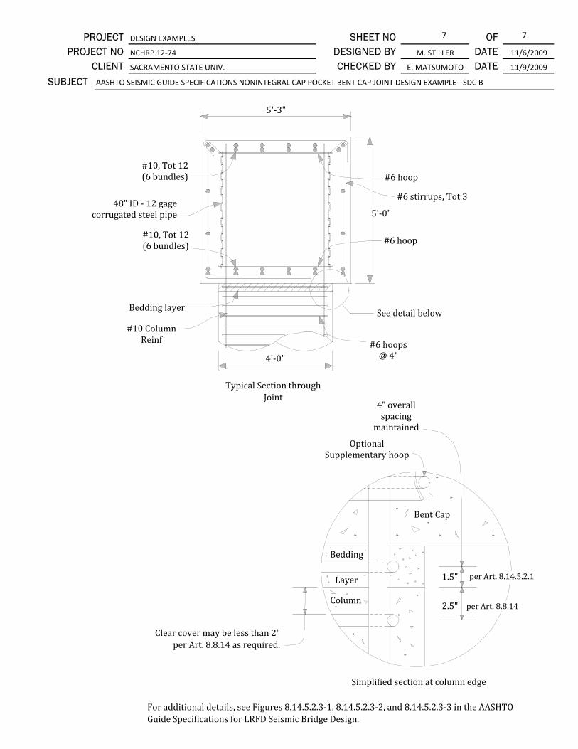
#6 stirrups, Tot 3
Bedding layer
#10 Column Reinf
See detail below
#10, Tot 12(6 bundles)
#10, Tot 12 (6 bundles)
#6 hoops@ 4"
5'‐3"
5'‐0"
4'‐0"
48" ID ‐ 12 gage corrugated steel pipe
Simplified Section at Column Edge
Clear cover may be less than 2" per Art. 8.8.14 as required.
Typical Section through
Bent Cap
Bedding
Layer
Column
4" overall spacing
maintained
1.5"
2.5"
per Art. 8.13.3.2.1
per Art. 8.8.14

6 6
PROJECT NO 11/9/2009
11/6/2009
CLIENT DATE DATE
SUBJECT AASHTO SEISMIC GUIDE SPECIFICATIONS NONINTEGRAL CAP POCKET BENT CAP JOINT DESIGN EXAMPLE ‐ SDC A
OF SHEET NO PROJECT DESIGN EXAMPLES
NCHRP 12‐74
SACRAMENTO STATE UNIV.
DESIGNED BY M. STILLER
CHECKED BY E. MATSUMOTO
#6 Stirrups, Tot 3#6 Stirrups @ 8" #6 Stirrups @ 8"
#10 Tot 12(6 bundles)
48" ID 12 gage corrugated metal pipe
Column
5'‐3"
Column Reinf
Plan View at Column Connection
For additional details, see Figures 8.13.4.2.3‐1, 8.13.4.2.3‐2, and 8.13.4.2.3‐3 in the AASHTO Guide Specifications for LRFD Seismic Bridge Design.

DESIGN FLOW CHART FOR CAST‐IN‐PLACE AND PRECAST BENT CAP JOINT DESIGN PER PROPOSED ARTICLE 8.15 (SDCs C AND D) AND ARTICLE 8.14 (SDC B)*
*Articles referenced in flow chart are for SDCs C and D; alternate article references for SDC B are shown italicized following the related SDCs C and D reference as applicable.
Joint performance shall satisfy Article 8.15.1; 8.14.1*. Evaluate principal tension and compression stresses in joint per Article 8.15.2.1 and concurrently satisfy Article 8.15.2.2.
IF: Principal tension < 0.11 ’ (Article 8.15.3.1)
IF: Dc ≤ d ≤ 1.25Dc (Eq. 8.15.5‐1)
Use strut & tie provisions of the AASHTO LRFD Bridge Design
Specifications and as approved by the Owner to determine joint
shear reinforcement.
IF: d < Dc or d > 1.25Dc (Eq. 8.15.5‐1)
Provide transverse confinement to satisfy ρs ≥ 0.11 ’ / fyh and ρs ≥ 0.40Ast /l2ac
(Eq. 8.15.3.1‐1) and (Eq. 8.15.3.1‐2)
Provide outside vertical joint shear stirrups: Asjvo ≥ 0.175Ast
(Eq. 8.15.5.1.1‐1)
Provide inside vertical joint shear stirrups: As
jvi ≥ 0.135Ast
(Eq. 8.15.5.1.2‐1)
Provide additional longitudinal reinforcement: Asjl ≥ 0.245Ast
(Eq. 8.15.5.1.3‐1)
IF: Cast‐In‐Place bent cap
Provide horizontal “J” bars per Article 8.15.5.1.4.
IF: Bedding layer ≤ 3” (Article 8.15.5.2.1)
IF: Bedding layer > 3” (Article 8.15.5.2.1)
Use Owner established provisions for bedding layer confinement and place top column hoop per Article 8.8.14.
Place bedding layer confinement per Article 8.15.5.2.1 and place top column hoop per Article 8.8.14.
IF: Precast “Cap pocket” connection
Provide horizontal “J” bars per Article 8.15.5.1.4.
Provide special analysis and detailing of joint.
See integral joint shear design flow chart
IF: Principal tension ≥ 0.11 ’ (Article 8.15.3.1)
IF: Bent connection is a “Knee” joint per Article 8.15; 8.14*
IF: Principal compression ≤ 0.25f’c and principal tension ≤ 0.38 ’ (Article 8.15.2.1)
IF: Principal compression > 0.25f’c or principal tension > 0.38 ’
(Article 8.15.2.1)
IF: Bent connection is a “T” joint per Article 8.15; 8.14*
IF: Bent cap is nonintegral
IF: Precast “Grouted duct” connection
Provide inside vertical joint shear stirrups: As
jvi ≥ 0.135Ast
(Eq. 8.15.5.1.2‐1)
Provide inside vertical joint shear stirrups: As
jvi ≥ 0.12Ast
(Eq. 8.15.5.2.3a‐1) Provide inside vertical joint shear stirrups: As
jvi ≥ 0.10Ast (Eq. 8.14.5.2.2a‐1) for grouted duct; As
jvi ≥ 0.10Ast (Eq. 8.14.5.2.3a‐1) for cap pocket; CIP Provisions TBD by Others.
IF: Bent connection is a “T” joint per Article 8.15;
8.14*
IF: Bent connection is a “Knee” joint per Article 8.15; 8.14*
IF: Bent cap is nonintegral
Provide special analysis and detailing of joint.
IF: Bent cap is integral
IF: SDCs C or D
IF: SDC B
TBD by Others Provide supplementary hoops per
Article 8.15.5.2.3a
IF: Bent cap is CIP in SDC B
IF: Bent cap is not CIP in SDC B TBD by
Others
Re‐proportion joint until the provisions of Article 8.15.2 are
satisfied.
Provide transverse confinement to
satisfy ρs ≥ 0.11 ’ / fyh (Eq. 8.15.3.1‐1)

1 7
Grouted Duct Joint Design Example For SDC B
Geometry and Design Parametersf'c = 4.0 ksi (specified compressive strength of bent cap)f'ce = 1.3f'c = 5.2 ksi (expected f'c of bent cap)f'cg = 7.5 ksi (specified compressive strength of grout)
Check: f'cg (ksi) ≥ max[1.25(f'ce+0.5)=7.0, 6.0)]OK per BCS 8.13.8.3.2a
fy = 60 ksi (yield stress of column bars)fye = 68 ksi (expected yield stress)fyh = 60 ksi (yield stress of hoops)
SHEET NO
CHECKED BY
OF DATE M. STILLER
AASHTO SEISMIC GUIDE SPECIFICATIONS NONINTEGRAL GROUTED DUCT BENT CAP JOINT DESIGN EXAMPLE ‐ SDC B
11/9/2009DATE DESIGNED BY PROJECT NO NCHRP 12‐74
E. MATSUMOTO
11/6/2009
PROJECT DESIGN EXAMPLES
SACRAMENTO STATE UNIV.CLIENT
Notes: 1. When the principal tensile stress exceeds the specified limit, the joint design follows the procedure found in the corresponding SDC C and D design example. 2. Knee joints such as that represented in C8.15.1 are not addressed in the current SGS, and special design provisions should be identified by the designer.
SUBJECT
AASHTO Guide Specifications for LRFD Seismic Bridge Design (SGS)
AASHTO LRFD Construction Specifications (BCS)
An SDC B grouted duct connection between a column and a precast bent cap is designed to produce performance similar to an SDC B cast‐in‐place connection; however, it is required that the principal stress in the connection be checked. This SDC B design example applies to a T‐joint of a rectangular, nonintegral precast bent cap supported by circular columns for which the principal tensile stress in the connection does not exceed 0.11√f'c. The applicable commentary sections in the AASHTO Guide Specifications for LRFD Seismic Bridge Design (SGS) provide additional background.
Ascaptop
Bent cap width = ft (Bcap)
Bent cap height ft (Ds)Stirrup bar size: #6
Column diameter = 4.0 ft (Dc)
Ast in2 (#10 Tot 20)
Hoop bar size: #6Hoop spacing = 4.0 in
Joint Performance SGS8.14.1
5.25= 5.00
Column sections (possibly governed by load cases other than Extreme Event (seismic) load case for SDC B) are analyzed to determine the idealized plastic moment capacity, Mp. Connections are designed for the lesser of two forces: 1) those produced by the column plastic hinging overstrength moment capacity, Mpo, or 2) unreduced elastic seismic moment in a column (i.e., the ultimate moment demand for seismic load combination, Mu). In the case where Mu exceeds Mp but not Mpo, Mpo is conservatively used for design because significant plastic hinging may develop. See Article 8.5 and C8.14.1 for further discussion.
Capacity of the bent cap section needs to satisfy applicable load combinations, including the Strength load cases and capacity protection during Extreme Event load cases. The bent cap section capacity is not investigated in this design example.
= 25.4
Typical cap section within Dc from face of column. Note: Bent cap reinforcement shown reflects that required by load combinations before application of joint shear design requirements.
Ascaptop
Ascapbot
Av
Bedding Layer
2 7SHEET NO
CHECKED BY
OF DATE M. STILLER
AASHTO SEISMIC GUIDE SPECIFICATIONS NONINTEGRAL GROUTED DUCT BENT CAP JOINT DESIGN EXAMPLE ‐ SDC B
11/9/2009DATE DESIGNED BY PROJECT NO NCHRP 12‐74
E. MATSUMOTO
11/6/2009
PROJECT DESIGN EXAMPLES
SACRAMENTO STATE UNIV.CLIENT
SUBJECT
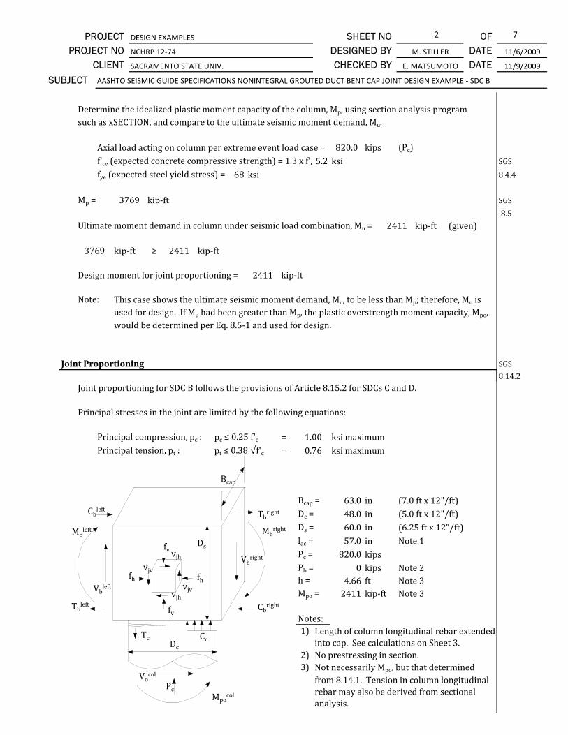
Axial load acting on column per extreme event load case = kips (Pc)f'ce (expected concrete compressive strength) = 1.3 x f'c 5.2 ksi SGS
fye (expected steel yield stress) = 68 ksi 8.4.4
Mp = kip‐ft SGS
8.5
Ultimate moment demand in column under seismic load combination, Mu = kip‐ft (given)
kip‐ft ≥ kip‐ft
Design moment for joint proportioning = kip‐ft
Note:
Joint Proportioning SGS
3769
2411
3769
2411
Determine the idealized plastic moment capacity of the column, Mp, using section analysis program such as xSECTION, and compare to the ultimate seismic moment demand, Mu.
820.0
This case shows the ultimate seismic moment demand, Mu, to be less than Mp; therefore, Mu is used for design. If Mu had been greater than Mp, the plastic overstrength moment capacity, Mpo, would be determined per Eq. 8.5‐1 and used for design.
2411
8.14.2Joint proportioning for SDC B follows the provisions of Article 8.15.2 for SDCs C and D.
Principal stresses in the joint are limited by the following equations:
Principal compression, pc : pc ≤ 0.25 f'c = ksi maximumPrincipal tension, pt : pt ≤ 0.38 √f'c = ksi maximum
Bcap = in (7.0 ft x 12"/ft)Dc = in (5.0 ft x 12"/ft)Ds = in (6.25 ft x 12"/ft)lac = in Note 1Pc = kipsPb = kips Note 2h = ft Note 3Mpo = kip‐ft Note 3
Notes:1)
2) No prestressing in section.3)
0.761.00
63.048.060.057.0820.0
04.662411
Not necessarily Mpo, but that determined from 8.14.1. Tension in column longitudinal rebar may also be derived from sectional analysis.
Length of column longitudinal rebar extended into cap. See calculations on Sheet 3.
fh fh
fv
fv
vjv
vjv
vjh
vjh
PcVocol
Mbleft
Tc Cc
Vbleft
Tbleft
Cbleft
Mbright
Vbright
Tbright
Cbright
Bcap
Ds
Dc
Mpocol

3 7SHEET NO
CHECKED BY
OF DATE M. STILLER
AASHTO SEISMIC GUIDE SPECIFICATIONS NONINTEGRAL GROUTED DUCT BENT CAP JOINT DESIGN EXAMPLE ‐ SDC B
11/9/2009DATE DESIGNED BY PROJECT NO NCHRP 12‐74
E. MATSUMOTO
11/6/2009
PROJECT DESIGN EXAMPLES
SACRAMENTO STATE UNIV.CLIENT
SUBJECT
pt = = = ksi Eq. 8.15.2.1‐3
pc = = = ksi Eq. 8.15.2.1‐4
vjv = Tc / Ajv = 517 k / 3591.0 in2 = ksi Eq. 8.15.2.1‐5
Ajv = lacBcap = 57.0 in x 63.0 in = in2 Eq. 8.15.2.1‐6
fv = Pc / Ajh = 820 k / 6804 in2 = ksi Eq. 8.15.2.1‐7
Ajh = (Dc + Ds) Bcap = (48.0 in + 60.0 in) x 63.0 in = in2 Eq. 8.15.2.1‐8
fh = = 0.0k / (63.0 in x 60.0 in) = ksi Eq. 8.15.2.1‐9
Tc = Mpo / h = 2411 kip‐ft / 4.66 ft = kips Eq. 8.15.2.1‐10
pc = ksi ≤ ksi maximum OKpt = ksi ≤ ksi maximum OK
0.096
0.216
0.761.00
3591.0
0.121
6804.0
0.0
517
0.216
0.144
Joint proportions are acceptable based on principal stress requirements.0.096
fh + fv2
+ fh ‐ fv2
+ v2jv
2
fh + fv2
‐ fh ‐ fv2
+ v2jv
2
PbBcapDs
0.0 + 0.1212
‐ +0.144 22
0.0 ‐ 0.1212
0.0 + 0.1212
+ +0.144 22
0.0 ‐ 0.1212
Minimum Development Length of Column Longitudinal Reinforcement SGS8.15.2.2
lac ≥ 2dbl fyeEq. 8.15.2.2.2‐1
dbl = in (#10 rebar)fye = ksif'cg = ksi = min (7.5 ksi, 7.0 ksi) per Article 8.15.2.2.2
lac = in (minimum)
Extend column reinforcement as far as practically possible, assume 3" clear from opposite face.
lac = Ds ‐ 3" = 5 ft x 12"/ft ‐ 3" in
in ≥ in minimum OK Extend to top face of cap less 3 in cover.
Minimum Joint Shear Reinforcing for Precast Bent Cap Connections SGS8.14.3
57.0
24.7
f'cg
Where the principal tension in the joint is less than 0.11√f'c and joint proportioning is acceptable per
Article 8.14.2 (8.15.2), the provisions of Article 8.14.5.2.2a for Asjvi and should reference Eq.
8.15.3.1‐1 for ρs are to be satisfied. However, other joint reinforcing (Asjvo, As
jl, and horizontal J‐bars) is not required.
1.27687.0
24.7
57.0

4 7SHEET NO
CHECKED BY
OF DATE M. STILLER
AASHTO SEISMIC GUIDE SPECIFICATIONS NONINTEGRAL GROUTED DUCT BENT CAP JOINT DESIGN EXAMPLE ‐ SDC B
11/9/2009DATE DESIGNED BY PROJECT NO NCHRP 12‐74
E. MATSUMOTO
11/6/2009
PROJECT DESIGN EXAMPLES
SACRAMENTO STATE UNIV.CLIENT
SUBJECT
Check if principal tension, pt, is ≥ 0.11√f'c (condition for likely joint cracking)
Calculated tension = ksiLimit, 0.11√ f'c = ksi
pt = ksi ≤ ksi limit Asjvi joint reinf. provisions of Article 8.14.5.2.2a apply.
Calculate required volumetric ratio of transverse joint reinforcement:
ρs ≥ 0.11 √f'c / fyh Eq. 8.15.3.1‐1
ρs ≥
ρs =
Asp = in2 (#6 hoop)D'gd = in (confined diameter of column between centroids of #6 hoop)s = in
0.0960.220
0.096 0.220
0.0037
Assume transverse reinforcement in the joint is the same size as the column plastic hinging region transverse reinforcement.
0.4445.9210.0 (trial spacing of transverse reinforcement hoops; spacing not
to exceed 12" or 0.3Ds per Art. 8.15.3.2.1)
4AspD'gd s
D'gd
D'gd =
D'gd = 48.0" ‐ 2" x 2 ‐ 0.88" ‐ 1.44" + 4" + 0.12" x 2 = in(deformed diameters are used for clearance calculations)
ρs =
ρs = ≥ minimum OK
Actual even spacing is 9.37 inches, total 6 hoops.Nonintegral Bent Cap Joint Shear Design SGS
8.14.5
Dc ≤ d ≤ 1.25Dc
Dc = ind = in
in ≤ in ≤ in OK Provisions of 8.14.5.2 apply
45.92
48.0 60.0 60.0
48.060.0
0.0038
0.0038 0.0037 10" spacing is adequate (Note: Common practice is to carry hoop spacing from column into cap, or s=4" in this case.)
Column diameter ‐ clear cover x 2 ‐ hoop diameter ‐ long. column reinf diameter + grouted duct inside diameter + corrugation amplitude x 2.
The depth of the cap with respect to the column diameter determines the method of joint shear design. When the following equation is satisfied, the joint shear design provisions of 8.14.5.2 apply. If the equation below is not satisfied, Strut‐and‐Tie model provisions of AASHTO LRFD Bridge Design Specifications apply.
D gd
Grouted DuctColumn Reinf.
Column
Hoop

5 7SHEET NO
CHECKED BY
OF DATE M. STILLER
AASHTO SEISMIC GUIDE SPECIFICATIONS NONINTEGRAL GROUTED DUCT BENT CAP JOINT DESIGN EXAMPLE ‐ SDC B
11/9/2009DATE DESIGNED BY PROJECT NO NCHRP 12‐74
E. MATSUMOTO
11/6/2009
PROJECT DESIGN EXAMPLES
SACRAMENTO STATE UNIV.CLIENT
SUBJECT
Vertical Stirrups Inside the Joint Region SGS8.14.5.2.2a
Asjvi ≥ 0.10 Ast Eq. 8.14.5.2.2a‐1
Ast = in2
Asjvi ≥ in2
Asjvi = 3 patterns x 2 legs / pattern x 0.44 in2/ leg = in2 ≥ in2 OK
Note:
Bedding Layer Reinforcement SGS8.14.5.2.1
Use #6 double U stirrups, Tot 3 patterns placed evenly through joint. Note that spacing may vary slightly to avoid conflict with grouted ducts.
The minimum number of stirrups is two, per Article 8.14.5.2.2a with a bar size no smaller than that used for bent cap stirrups.
Provide bedding layer transverse reinforcement to match the size and type used in the column
2.64 2.54
2.54
25.40
Figures Showing Final Design
Elevation View at Column Connection
plastic hinging region (#6 bar). Hoop will be placed at mid‐height in the bedding layer; bedding layer to be 3" thick. Cover on top column hoop to be 2" as shown in figures below, and resulting center to center spacing of transverse reinforcement is 4" throughout, in accordance with Article 8.8.14.
#6 Stirrups, Tot 3
#6 Stirrups @ 8"
#10, Tot 12, Typ#10, Tot 3 each face
#6 bedding hoop

6 7SHEET NO
CHECKED BY
OF DATE M. STILLER
AASHTO SEISMIC GUIDE SPECIFICATIONS NONINTEGRAL GROUTED DUCT BENT CAP JOINT DESIGN EXAMPLE ‐ SDC B
11/9/2009DATE DESIGNED BY PROJECT NO NCHRP 12‐74
E. MATSUMOTO
11/6/2009
PROJECT DESIGN EXAMPLES
SACRAMENTO STATE UNIV.CLIENT
SUBJECT
#6 stirrups, Tot 3
See detail below
#6 hoops @ 4"
#10 Column Reinf
Bedding layer
#10, Tot 12(6 bundles)
#6 hoops, Tot 6, even spacing
#10, Tot 12(6 bundles)
5'‐3"
5'‐0"
4'‐0"
Simplified Section at Column Edge
Clear cover may be less than 2" per Art. 8.8.14 as required.
Typical Section through Joint
4" overall spacing maintained
Bent Cap
Bedding
Layer
Column
1.5"
2.5"
per Art. 8.14.5.2.1
per Art. 8.8.14

7 7SHEET NO
CHECKED BY
OF DATE M. STILLER
AASHTO SEISMIC GUIDE SPECIFICATIONS NONINTEGRAL GROUTED DUCT BENT CAP JOINT DESIGN EXAMPLE ‐ SDC B
11/9/2009DATE DESIGNED BY PROJECT NO NCHRP 12‐74
E. MATSUMOTO
11/6/2009
PROJECT DESIGN EXAMPLES
SACRAMENTO STATE UNIV.CLIENT
SUBJECT
Plan View at Column Connection
5'‐3"
Grouted Duct Column
#6 Hoops
#10, Tot 12(6 bundles)
#6 Stirrups, Tot 3#6 Stirrups @ 8" #6 Stirrups @ 8"
For additional details, see Figures 8.14.5.2.2‐1, 8.14.5.2.2‐2, and 8.14.5.2.2‐3 in the AASHTO Guide Specifications for LRFD Seismic Bridge Design.

1 7
Cap Pocket Joint Design Example For SDC B
Geometry and Design Parametersf'c = 4.0 ksi (specified compressive strength of bent cap)f'ce =1.3f'c = 5.2 ksi (expected f'c of bent cap)f'c_pocket: (specified compressive strength of pocket fill)
Select cap pocket strength to satisfy BCS.f'c_pocket = 1.3 f'ce + 0.5 ksi = 5.7 ksi (BCS 8.13.8.3.3a)
fyh (yield stress of equivalent hoop)fyp (nominal yield stress of steel pipe)θ (angle between horizontal axis of cap and
AASHTO Guide Specifications for LRFD Seismic Bridge Design (SGS)
DESIGNED BY M. STILLER DATE 11/6/2009
DATE 11/9/2009
OF SHEET NO PROJECT DESIGN EXAMPLES
PROJECT NO NCHRP 12‐74
SUBJECT AASHTO SEISMIC GUIDE SPECIFICATIONS NONINTEGRAL CAP POCKET BENT CAP JOINT DESIGN EXAMPLE ‐ SDC B
CHECKED BY E. MATSUMOTOCLIENT SACRAMENTO STATE UNIV.
AASHTO LRFD Construction Specifications (BCS)Notes: 1. When the principal tensile stress exceeds the specified limit, the joint design follows the procedure
found in the corresponding SDC C and D design example. 2. Knee joints such as that represented in C8.15.1 are not addressed in the current SGS, and special design provisions should be identified by the designer.
An SDC B cap pocket connection between a column and a precast bent cap reinforces the joint by means of a helical lock‐seam, corrugated steel pipe, eliminating conventional hoops and J‐bars. This SDC B design example applies to a T‐joint of a rectangular, nonintegral precast bent cap supported by circular columns for which the principal tensile stress in the connection does not exceed 0.11√f'c. The applicable commentary sections in the AASHTO Guide Specifications for LRFD Seismic Bridge Design (SGS) provide additional background.
Ascaptop
Aθ (angle between horizontal axis of cap and
pipe helical corrugation or lock seam)fy = 60 ksi (yield stress of column bars)fye = 68 ksi (expected yield stress of column bars)
Bent cap width = ft (Bcap)
Bent cap height ft (Ds)Stirrup bar size: #6
Column diameter = 4.0 ft (Dc)
Ast in2 (#10 Tot 20)
Hoop bar size: #6Hoop spacing = 4.0 in
Joint Performance SGS8.14.1
= 5.00
= 25.4Typical cap section within Dc from face of column. Note: Bent cap reinforcement shown reflects that required by load combinations before application of joint shear design requirements.
Column sections (possibly governed by load cases other than Extreme Event (seismic) load case for SDC B) are analyzed to determine the idealized plastic moment capacity, Mp. Connections are designed for the lesser of two forces: 1) those produced by the column plastic hinging overstrength moment capacity, Mpo, or 2) unreduced elastic seismic moment in a column (i.e., the ultimate moment demand for seismic load combination, Mu). In the case where Mu exceeds Mp but not Mpo, Mpo is conservatively used for design because significant plastic hinging may develop. See Article 8.5 and C8.14.1 for further discussion.
Capacity of the bent cap section needs to satisfy applicable load combinations, including the Strength load cases and capacity protection during Extreme Event load cases. The bent cap section capacity is not investigated in this design example.
5.25
Ascaptop
Ascapbot
Av
Bedding Layer

2 7
DESIGNED BY M. STILLER DATE 11/6/2009
DATE 11/9/2009
OF SHEET NO PROJECT DESIGN EXAMPLES
PROJECT NO NCHRP 12‐74
SUBJECT AASHTO SEISMIC GUIDE SPECIFICATIONS NONINTEGRAL CAP POCKET BENT CAP JOINT DESIGN EXAMPLE ‐ SDC B
CHECKED BY E. MATSUMOTOCLIENT SACRAMENTO STATE UNIV.
Axial load acting on column per extreme event load case = kips (Pc)f'ce (expected concrete compressive strength) = 1.3 x f'c 5.2 ksi SGS
fye (expected steel yield stress) = 68 ksi 8.4.4
Mp = kip‐ft SGS
8.5
Maximum moment in column under seismic load application, Mu = kip‐ft
kip‐ft ≥ kip‐ft
Design moment for joint proportioning = kip‐ft
Note:
Joint Proportioning SGS8.14.2
f f f f
24113769
Determine the idealized plastic moment capacity of the column, Mp, using section analysis program such as xSECTION, and compare to the ultimate seismic moment demand, Mu.
820.0
2411
This case shows the ultimate seismic moment demand, Mu, to be less than Mp; therefore, Mu is used for design. If Mu had been greater than Mp, the plastic overstrength moment capacity, Mpo, would be determined per Eq. 8.5‐1 and used for design.
3769
2411
Joint proportioning for SDC B follows the provisions of Article 8.15.2 for SDCs C and D.
Principal stresses in the joint are limited by the following equations:
Principal compression, pc : pc ≤ 0.25 f'c = ksi maximumPrincipal tension, pt : pt ≤ 0.38 √f'c = ksi maximum
Bcap = in (7.0 ft x 12"/ft)Dc = in (5.0 ft x 12"/ft)Ds = in (6.25 ft x 12"/ft)lac = in Note 1Pc = kipsPb = kips Note 2h = ft Note 3Mpo = kip‐ft Note 3
Notes:1)
2) No prestressing in section.3)
4.662411
Length of column longitudinal rebar extended into cap. See calculations on Sheet 3.
48.060.057.0820.0
1.00
Not necessarily Mpo, but that determined from 8.14.1. Tension in column longitudinal rebar may also be derived from sectional analysis.
0
0.76
63.0
fh fh
fv
fv
vjv
vjv
vjh
vjh
PcVocol
Mbleft
Tc Cc
Vbleft
Tbleft
Cbleft
Mbright
Vbright
Tbright
Cbright
Bcap
Ds
Dc
Mpocol

3 7
DESIGNED BY M. STILLER DATE 11/6/2009
DATE 11/9/2009
OF SHEET NO PROJECT DESIGN EXAMPLES
PROJECT NO NCHRP 12‐74
SUBJECT AASHTO SEISMIC GUIDE SPECIFICATIONS NONINTEGRAL CAP POCKET BENT CAP JOINT DESIGN EXAMPLE ‐ SDC B
CHECKED BY E. MATSUMOTOCLIENT SACRAMENTO STATE UNIV.
pt = = = ksi Eq. 8.15.2.1‐3
pc = = = ksi Eq. 8.15.2.1‐4
vjv = Tc / Ajv = 517 k / 3591.0 in2 = ksi Eq. 8.15.2.1‐5
Ajv = lacBcap = 57.0 in x 63.0 in = in2 Eq. 8.15.2.1‐6
fv = Pc / Ajh = 820 k / 6804 in2 = ksi Eq. 8.15.2.1‐7
Ajh = (Dc + Ds) Bcap = (48.0 in + 60.0 in) x 63.0 in = in2 Eq. 8.15.2.1‐8
fh = = 0.0k / (63.0 in x 60.0 in) = ksi Eq. 8.15.2.1‐9
Tc = Mpo / h = 2411 kip‐ft / 4.66 ft = kips Eq. 8.15.2.1‐10
pc = ksi ≤ ksi maximum OKpt = ksi ≤ ksi maximum OK
0.0
3591.0
0.121
6804.0
517
0.096
0.216 1.00 Joint proportions are acceptable based on principal stress requirements.0.096 0.76
0.216
0.144
fh + fv2
+ fh ‐ fv2
+ v2jv
2
fh + fv2
‐ fh ‐ fv2
+ v2jv
2
PbBcapDs
0.0 + 0.1212
‐ +0.144 22
0.0 ‐ 0.1212
0.0 + 0.1212
+ +0.144 22
0.0 ‐ 0.1212
Minimum Development Length for Column Longitudinal Reinforcement SGS8.15.2.2
lac ≥ 2.3dbl fyeEq. 8.15.2.2.2‐2
dbl = in (#10 rebar)fye = ksif'c = ksi (cap pocket concrete) = min (5.7 ksi, 7.0 ksi) per Article 8.15.2.2.2
lac = in (minimum)
Extend column reinforcement as far as practically possible, assume 3" clear from opposite face.
lac = Ds ‐ 3" = 5.0 ft x 12"/ft ‐ 3" = in
in ≥ in minimum OK Extend to top face of cap less 3 in cover.
Minimum Joint Reinforcing for Precast Bent Cap Connections SGS8.14.3
f'c
Where the principal tension in the joint is less than 0.11√f'c and joint proportioning is acceptable per
Article 8.14.2 (8.15.2), the provisions of Article 8.14.5.2.3 for Asjvi. Eq. 8.15.3.1‐1 for joint transverse
reinforcement (i.e., pipe thickness) is to be satisfied. However, other joint reinforcing (Asjvo, As
jl) is not required.
1.27
34.8
57.0 34.8
57.0
685.7

4 7
DESIGNED BY M. STILLER DATE 11/6/2009
DATE 11/9/2009
OF SHEET NO PROJECT DESIGN EXAMPLES
PROJECT NO NCHRP 12‐74
SUBJECT AASHTO SEISMIC GUIDE SPECIFICATIONS NONINTEGRAL CAP POCKET BENT CAP JOINT DESIGN EXAMPLE ‐ SDC B
CHECKED BY E. MATSUMOTOCLIENT SACRAMENTO STATE UNIV.
Check if principal tension, pt, is ≥ 0.11√f'c (condition for likely joint cracking)
Calculated tension = ksiLimit, 0.11√ f'c = ksi
pt = ksi ≤ ksi limit Asjvi joint reinf. provisions of Article 8.14.5.2.3b apply.
Calculate required volumetric ratio of transverse joint reinforcement:
ρs ≥ 0.11 √f'c / fyh Eq. 8.15.3.1‐1
ρs ≥
SGS8.15.3.2.2
ρs = s =
Asp = in2 (assume #6 hoop to match column transverse reinforcement)D'cp = in (average confined dia. of column between corrugated steel pipe walls)
( i i l t i ti )
0.4448.650 0037
0.0960.220
0.096 0.220
0.004
Use the minimum volumetric ratio to calculate the required number of equivalent #6 hoops per unit length of corrugated steel pipe. Use a unit length of 1 foot. Use a 48" ID corrugated pipe based on the outer diameter of column reinforcement pattern.
4AspD'cp s
4AspD'cp ρs
ρs = (minimum volumetric ratio)
Corrugated steel pipe
D'cp
D'cp = Nominal inside diameter of corrugated pipe + average wall corrugation width.
s = in max spacingTherefore, the number of equivalent hoops per foot is 12" / s = hoops/ft
Calculate the nominal confining hoop force of the equivalent hoops.
FH = nh Asp fyh Eq. 8.15.3.2.2‐2
nh = ea (number of equivalent hoops per unit length)
Asp = in2 (area of #6 equivalent hoop)fyh = ksi (yield stress of equivalent hoop)
FH = kips/ft
tpipe ≥ max Eq. 8.15.3.2.2‐1
0.0037
60.0
32.11
9.91.216
Calculate the thickness of the corrugated steel pipe that provides the same nominal confinement as standard hoop reinforcement.
1.216
0.44
FHHp fyp cosθ
0.060 in

5 7
DESIGNED BY M. STILLER DATE 11/6/2009
DATE 11/9/2009
OF SHEET NO PROJECT DESIGN EXAMPLES
PROJECT NO NCHRP 12‐74
SUBJECT AASHTO SEISMIC GUIDE SPECIFICATIONS NONINTEGRAL CAP POCKET BENT CAP JOINT DESIGN EXAMPLE ‐ SDC B
CHECKED BY E. MATSUMOTOCLIENT SACRAMENTO STATE UNIV.
FH = kips/ftHp = in/ft (specified unit length)fyp = ksi (manufacturer specified)θ = deg (manufacturer specified)
tpipe ≥ in
Use a 12 gage corrugated steel pipe, 48" nominal inside diameter. tpipe = in
As a check, compare minimum tpipe from Eq. 8.15.3.2.2‐1 to simplified equation in the commentary:
tpipe ≥ 0.04 = in and ≥ 0.06 in (Note: f'c refers to cap pocket) Eq. C8.15.3.2.2‐1
Nonintegral Bent Cap Joint Shear Design SGS8.14.5
30.020.0
If the refined equation (Eq. 8.15.3.2.2‐1) is not used, the maximum of these two simplified equations may be used because they provide a more conservative value. Note that the controlling thickness of 0.1381" from commentary equations is considerably larger than the 0.0949" calculated from the refined specification equation. Use of the refined equation reduces the required pipe thickness, especially for larger diameter pipes.
0.0949
0.1381
Depth of the cap with respect to the column diameter determines the method of joint shear design When
0.105
32.112.0
D'cp √f'cfyp cosθ
Dc ≤ d ≤ 1.25Dc
Dc = ind = in
in ≤ in ≤ in OK Provisions of 8.14.5.2 apply
Vertical Stirrups Inside the Joint Region SGS
Asjvi ≥ 0.10 Ast Eq. 8.14.5.2.3.a‐1
Ast = in2
Asjvi ≥ in2
Use #6 double U stirrups, Tot 3 patterns placed evenly through joint.
Asjvi = 3 patterns x 2 legs/ pattern x 0.44 in2/ leg = in2 ≥ in2 OK
48.0 60.0 60.0
2.54
60.048.0
25.40
2.64
Depth of the cap with respect to the column diameter determines the method of joint shear design. When the following equation is satisfied, the joint shear design provisions of Article 8.14.5.2 apply. If the equation below is not satisfied, Strut‐and‐Tie model provisions of AASHTO LRFD Bridge Design Specifications apply.
Note the minimum number of stirrups is two per Article 8.15.5.2.3a with a bar size no smaller than that used for bent cap stirrups.
2.54

6 7
DESIGNED BY M. STILLER DATE 11/6/2009
DATE 11/9/2009
OF SHEET NO PROJECT DESIGN EXAMPLES
PROJECT NO NCHRP 12‐74
SUBJECT AASHTO SEISMIC GUIDE SPECIFICATIONS NONINTEGRAL CAP POCKET BENT CAP JOINT DESIGN EXAMPLE ‐ SDC B
CHECKED BY E. MATSUMOTOCLIENT SACRAMENTO STATE UNIV.
Bedding Layer Reinforcement SGS8.14.5.2.1
Supplementary Hoops SGS8.14.5.2.3.b
Figures Showing Final Design
Provide bedding layer transverse reinforcement to match the size and type used in the column plastic hinging region (#6 bar). Hoop will be placed at mid‐height in the bedding layer; bedding layer to be 3" thick. Cover on top column hoop to be 2" as shown in figures below and resulting center to center spacing of transverse reinforcement is 4" throughout, in accordance with Article 8.8.14.
A supplementary hoop may be optionally placed one inch from each end of the corrugated steel pipe. The area of this bar is to be no less than that provided in the column plastic region (use #6
#6 Stirrups #10, Tot 12, Typ#10, Tot 3 each face
Elevation View at Column Connection
Plan View at Column Connection
#6 Stirrups, Tot 3
#6 bedding hoop
#6 Stirrups, Tot 3#6 Stirrups @ 8" #6 Stirrups @ 8"
#10, Tot 12(6 bundles)
48" ID 12 gage corrugated metal pipe
Column
#6 Supplementary hoop(optional)
Column Reinf
5'‐3"
7 7
DESIGNED BY M. STILLER DATE 11/6/2009
DATE 11/9/2009
OF SHEET NO PROJECT DESIGN EXAMPLES
PROJECT NO NCHRP 12‐74
SUBJECT AASHTO SEISMIC GUIDE SPECIFICATIONS NONINTEGRAL CAP POCKET BENT CAP JOINT DESIGN EXAMPLE ‐ SDC B
CHECKED BY E. MATSUMOTOCLIENT SACRAMENTO STATE UNIV.
#6 stirrups, Tot 3
#6 hoop
#6 hoop
Bedding layer
#10 Column Reinf
See detail below
#10, Tot 12(6 bundles)
#10, Tot 12(6 bundles)
#6 hoops@ 4"
5'‐3"
5'‐0"
4'‐0"
48" ID ‐ 12 gagecorrugated steel pipe
Simplified section at column edge
For additional details, see Figures 8.14.5.2.3‐1, 8.14.5.2.3‐2, and 8.14.5.2.3‐3 in the AASHTO Guide Specifications for LRFD Seismic Bridge Design.
Typical Section through Joint
Clear cover may be less than 2" per Art. 8.8.14 as required.
Bent Cap
Bedding
Layer
Column
4" overall spacing
maintained
Optional Supplementary hoop
1.5"
2.5"
per Art. 8.14.5.2.1
per Art. 8.8.14

1 8
Grouted Duct Joint Design Example For SDCs C and D
Geometry and Design Parameters f'c = 4.0 ksi (specified compressive strength of bent cap concrete)f'ce = 1.3f'c = 5.2 ksi (expected f'c of bent cap)f'cg = 7.5 ksi (specified compressive strength of grout)
Check: f'cg (ksi) ≥ max[1.25(f'ce+0.5)=7.1, 6.0)]OK per BCS 8.13.8.3.2a
fy = 60 ksi fye = 68 ksi (column bars)Bent cap width = 7.0 ft (Bcap)
Bent cap height ft (Ds)Stirrup bar size: #6Requirements for Extreme I load case in cap:
11/6/2009
AASHTO Guide Specifications for LRFD Seismic Bridge Design (SGS)
11/9/2009
OF
Grouted duct connection between a column and a precast bent cap in SDC's C and D is designed to produce performance similar to a cast‐in‐place connection in SDC's C and D. This SDCs C and D design example applies to a T‐joint of a rectangular, nonintegral precast bent cap supported by circular columns for which the principal tension stress in the connection exceeds 0.11√f'c. In this case, the connection requires additional joint reinforcement. The applicable commentary sections in the AASHTO Guide Specifications for LRFD Seismic Bridge Design (SGS) provide additional background.
SUBJECT
SHEET NO DESIGNED BY CHECKED BY
PROJECT DESIGN EXAMPLES
AASHTO LRFD Bridge Construction Specifications (BCS)
DATE DATE
AASHTO SEISMIC GUIDE SPECIFICATIONS NONINTEGRAL GROUTED DUCT BENT CAP JOINT DESIGN EXAMPLE ‐ SDCs C and D
M. STILLER
= 6.25
SACRAMENTO STATE UNIV.
PROJECT NO NCHRP 12‐74
CLIENT
Notes: 1. The SDC B design example illustrates the procedure to be followed when the 0.11√f'c limit is not exceeded. 2. Knee joints such as that represented in C8.15.1 are not addressed in the current SGS, and special design provisions should be identified by the designer.
E. MATSUMOTO
Ascaptop
Av
Requirements for Extreme I load case in cap:
Top cap reinf, Ascap
top = in2
Bot cap reinf, Ascap
bot = in2
Shear reinf, Av = in2/ft
Column diameter = 5.0 ft (Dc)
Ast in2 (#11, Tot 20)
Hoop bar size: #6Hoop spacing = 4.0 in fyh = 60 ksi (yield stress of hoops)
Joint Performance SGS8.15.1
Note:
Axial load acting on column per extreme event load case = kips (Pc)f'ce (expected concrete compressive strength) = 1.3 x f'c 5.2 ksi SGS
fye (expected steel yield stress) = 68 ksi (column bars) 8.4.4
= 31.2
4.12
16.77
11.40
Capacity of the bent cap section needs to satisfy applicable load combinations, including the Strength load cases and capacity protection during Extreme Event load cases. The bent cap section capacity is not investigated in this design example.
Determine the idealized plastic moment capacity of the column, Mp, using section analysis program such as xSECTION, and calculate the overstrength moment capacity, Mpo, per Article 8.5.
Typical cap section within Dc from face of column. Note: Bent cap reinforcement shown reflects that required by Extreme Event I load combination before application of joint shear design requirements.
Moment resisting connections are designed to transmit the maximum forces produced when the column reaches its overstrength moment capacity, Mpo.
820.0
Ascaptop
Ascapbot
Av
Bedding Layer

2 8
11/6/2009
11/9/2009
OF
SUBJECT
SHEET NO DESIGNED BY CHECKED BY
PROJECT DESIGN EXAMPLES
DATE DATE
AASHTO SEISMIC GUIDE SPECIFICATIONS NONINTEGRAL GROUTED DUCT BENT CAP JOINT DESIGN EXAMPLE ‐ SDCs C and D
M. STILLER
SACRAMENTO STATE UNIV.
PROJECT NO NCHRP 12‐74
CLIENT E. MATSUMOTO
Mp = kip‐ft SGS
Mpo = λmo Mp 8.5
λmo = 1.2 (ASTM A706) Eq. 8.5‐1Mpo = kip‐ft
Joint Proportioning SGS8.15.2
Principal Stresses
Principal stresses in the joint are limited by the following equations:
Principal compression, pc : pc ≤ 0.25 f'c = ksi maximumPrincipal tension, pt : pt ≤ 0.38 √f'c = ksi maximum
Bcap = in (7.0 ft x 12"/ft)Dc = in (5.0 ft x 12"/ft)Ds = in (6.25 ft x 12"/ft)lac = in Note 1Pc = kips
60.075.0
820
5970
1.00
7164
0.76
72.0
84.0
fv vjh
Mbleft
Cbleft
Mbright
Vbright
Tbright
Bcap
Dsc pPb = kips Note 2h = ft Note 3Mpo = kip‐ft Note 3
Notes:
1)
2) No prestressing in section.3)
pt = = = ksi Eq. 8.15.2.1‐3
pc = = = ksi Eq. 8.15.2.1‐4
vjv = Tc / Ajv = 1890 k / 6048.0 in2 = ksi Eq. 8.15.2.1‐5
Ajv = lacBcap = 72.0 in x 84.0 in = in2 Eq. 8.15.2.1‐6
fv = Pc / Ajh = 820 k / 11340 in2 = ksi Eq. 8.15.2.1‐7
0.313
6048.0
0.0723
0.278
7164
Length of column longitudinal rebar extended into cap. See calculations below.
0
Determined from sectional analysis. Tension in column longitudinal rebar may also be derived from sectional analysis.
3.79
0.351fh + fv2
+ fh ‐ fv2
+ v2jv
2
fh + fv2
‐ fh ‐ fv2
+ v2jv
20.0 + 0.072
2‐ +0.313 2
20.0 ‐ 0.072
2
0.0 + 0.0722
+ +0.313 22
0.0 ‐ 0.0722
fh fh
fv
vjv
vjvjh
vjh
PcVocol
Tc Cc
Vbleft
Tbleft
Vbright
Cbright
Dc
Mpocol

3 8
11/6/2009
11/9/2009
OF
SUBJECT
SHEET NO DESIGNED BY CHECKED BY
PROJECT DESIGN EXAMPLES
DATE DATE
AASHTO SEISMIC GUIDE SPECIFICATIONS NONINTEGRAL GROUTED DUCT BENT CAP JOINT DESIGN EXAMPLE ‐ SDCs C and D
M. STILLER
SACRAMENTO STATE UNIV.
PROJECT NO NCHRP 12‐74
CLIENT E. MATSUMOTO
Ajh = (Dc + Ds) Bcap = (60.0 in + 75.0 in) x 84.0 in = in2 Eq. 8.15.2.1‐8
fh = = 0.0k / (84.0 in x 75.0 in) = ksi Eq. 8.15.2.1‐9
Tc = Mpo / h = 7164 kip‐ft / 3.79 ft = kips Eq. 8.15.2.1‐10
pc = ksi ≤ ksi maximum OKpt = ksi ≤ ksi maximum OK
Minimum Development Length of Column Longitudinal Reinforcement SGS8.15.2.2
lac ≥ 2 dbl fyeEq. 8.15.2.2.2‐1
dbl = in (#11 rebar)fye = ksif'cg = ksi = min (7.5 ksi, 7.0 ksi) per Article 8.15.2.2.2
lac = in (minimum)
1.00
11340
0.0
0.278
27.4
1.4168
f'cg
0.351
7.0
0.76
Extend column reinforcement as far as practically possible; assume 3" clear from opposite face, per Article 8 15 2 2 2
Joint proportions are acceptable based on principal stress requirements.
1890
PbBcapDs
lac = Ds ‐ 3" = 6.25 ft x 12"/ft ‐ 3" = in
in ≥ in (minimum) OK Extend to top face of cap less 3 in cover.
Minimum Joint Shear Reinforcing for Precast Bent Cap Connections SGS8.15.3
Check if principal tension, pt, is ≥ 0.11√f'c (condition for likely joint cracking)
Calculated tension = ksiLimit, 0.11√ f'c = ksi
pt = ksi ≥ ksi limit
Calculate required volumetric ratio of transverse joint reinforcement:
Maximum of: ρs ≥ 0.11 √f'c / fyh Eq. 8.15.3.1‐1
ρs ≥ 0.40 Ast / l2ac Eq. 8.15.3.1‐2
Ast = in2
lac = in
72.0
0.220
72.031.2
0.220
72.0
0.278
0.278
per Article 8.15.2.2.2.
Where principal tension in the joint is greater than or equal to 0.11√ f'c and joint proportioning is acceptable per Article 8.15.2, additional transverse joint reinforcement for cap pocket connections per Article 8.15.5.2.3 is to be added, and Eqs. 8.15.3.1‐1 and 8.15.3.1‐2 are to be satisfied.
Additional joint reinforcement (Asjvo, As
jvi, Asjl, and
horizontal J bars) is required.
27.4

4 8
11/6/2009
11/9/2009
OF
SUBJECT
SHEET NO DESIGNED BY CHECKED BY
PROJECT DESIGN EXAMPLES
DATE DATE
AASHTO SEISMIC GUIDE SPECIFICATIONS NONINTEGRAL GROUTED DUCT BENT CAP JOINT DESIGN EXAMPLE ‐ SDCs C and D
M. STILLER
SACRAMENTO STATE UNIV.
PROJECT NO NCHRP 12‐74
CLIENT E. MATSUMOTO
Maximum of: 0.11 √f'c / fyh = governs Eq. 8.15.3.1‐1
0.40 Ast / l2ac = Eq. 8.15.3.1‐2
Use ρs ≥
ρs =
Asp = in2 (#6 hoop)D'gd = in (confined diameter of column between centroids of #6 hoop)s = in
D'gd =
D'gd = 60.0" ‐ 2" x 2 ‐ 0.88" ‐ 1.44" + 4" + 0.12" x 2 = in
(trial spacing of transverse reinforcement hoops; spacing not to exceed 12" or 0.3Ds per Art. 8.15.3.2.1)
8.0
0.0024
0.0037
Column diameter ‐ clear cover x 2 ‐ hoop diameter ‐ long. column reinf diameter + grouted duct inside diameter + corrugation amplitude x 2.
0.4457.92
Assume transverse reinforcement in the joint is the same size as the column plastic hinging region transverse reinforcement.
57.92
0.0037
4AspD'gd s
D'gd
Grouted Duct
Column Reinf.
Hoop
gd 60.0 2 x 2 0.88 1.44 4 0.12 x 2 in(deformed diameters are used for clearance calculations)
ρs =
ρs = ≥ minimum OK
Actual even spacing is 7.89 inches, total 9 hoops.Nonintegral Bent Cap Joint Shear Design SGS
8.15.5
Dc ≤ d ≤ 1.25Dc
Dc = ind = in
in ≤ in ≤ in OK Provisions of 8.15.5.2 apply
Additional Joint Shear Reinforcement SGS8.15.5.2.2
75.0
75.0
8" spacing is adequate (Note: Common practice is to carry hoop spacing from column into cap, or s=4" in this case.)
0.0037
The depth of the cap with respect to the column diameter determines the method of joint shear design. When the following equation is satisfied, the joint shear design provisions of Article 8.15.5.2 apply. If the equation below is not satisfied, Strut‐and‐Tie model provisions of AASHTO LRFD Bridge Design Specifications apply.
60.0
60.0
Grouted duct connections follow essentially the same joint reinforcing requirements as for cast‐in‐place connections specified in Art. 8.15.5.1, when additional reinforcement is required per Art. 8.15.3.2.1
0.0038
75.0
0.0038
57.92Column

5 8
11/6/2009
11/9/2009
OF
SUBJECT
SHEET NO DESIGNED BY CHECKED BY
PROJECT DESIGN EXAMPLES
DATE DATE
AASHTO SEISMIC GUIDE SPECIFICATIONS NONINTEGRAL GROUTED DUCT BENT CAP JOINT DESIGN EXAMPLE ‐ SDCs C and D
M. STILLER
SACRAMENTO STATE UNIV.
PROJECT NO NCHRP 12‐74
CLIENT E. MATSUMOTO
Vertical Stirrups Outside the Joint Region:
Asjvo ≥ 0.175 Ast Eq. 8.15.5.1.1‐1
Ast = in2
Asjvo ≥ in2
Asjvo ≥ in2 / Dc = in2 /ft
Avtotal = Av + As
jvo
Avtotal = 4.12 in2/ft + 1.09 in2/ft = in2 /ft
Area of one stirrup pattern = 4 legs x 0.44 in2/ leg = in2
Asjvo is placed transversely within a distance Dc extending from each face of the column. This is
in addition to the Av of 4.12 in2 provided for Extreme I load case analysis per Article 8.15.5.1.1.
5.21
5.46 1.092
Find the spacing of the #6 stirrups within the distance Dc on both sides of the column with the assumption of #6 stirrups having four vertical legs in each pattern.
31.20
1.76
5.46
Number of stirrup patterns required per foot = Avtotal/1.76 in2 = stirrups / ft
Use 3 stirrups per foot, 4" spacing. Avtotal = in2/ft ≥ in2/ft OK
Vertical Stirrups Inside the Joint Region:
Asjvi ≥ 0.135 Ast Eq. 8.15.5.1.2‐1
Ast = in2
Asjvi ≥ in2
Asjvi = 4 patterns x 4 legs / pattern x 0.44 in2/ leg = in2 ≥ in2 OK
4 patterns instead of 3 are conservatively used for symmetry.
Additional Longitudinal Cap Beam Reinforcement
Asjl ≥ 0.245 Ast Eq. 8.15.5.1.3‐1
Ast = in2
Asjl ≥ in2 (individual amount applied to top and bottom faces of cap)
5.28
2.96
5.21
7.64
4.21
Use #6 double U stirrups, Tot 4 patterns placed evenly through joint. Note that spacing may vary slightly to avoid conflict with grouted ducts. The minimum number of stirrups is two, per Article 8.15.5.2.2, with a bar size no smaller than that used for bent cap stirrups.
31.2
= 31.2
7.04 4.21

6 8
11/6/2009
11/9/2009
OF
SUBJECT
SHEET NO DESIGNED BY CHECKED BY
PROJECT DESIGN EXAMPLES
DATE DATE
AASHTO SEISMIC GUIDE SPECIFICATIONS NONINTEGRAL GROUTED DUCT BENT CAP JOINT DESIGN EXAMPLE ‐ SDCs C and D
M. STILLER
SACRAMENTO STATE UNIV.
PROJECT NO NCHRP 12‐74
CLIENT E. MATSUMOTO
Top cap reinf, Ascap
top = in2
Bot cap reinf, Ascap
bot = in2
Total top cap reinf, Astotal
top = Ascap
top + Asjl = 16.77 in2 + 7.64 in2 = 24.41 in2
Total bot cap reinf, Astotal
bot = Ascap
bot + Asjl = 11.40 in2 + 7.64 in2 = 19.04 in2
Use #11 Tot 16 on top and bottom of bent cap, As = 24.96 in2
Horizontal JBars SGS8.15.5.1.4
Bedding Layer Reinforcement SGS8.15.5.2.1
11.40
16.77Per design requirements of Extreme I load case.
Provide bedding layer transverse reinforcement to match the size and type used in the column
Provide horizontal J‐bars hooked around every other vertical‐to‐longitudinal side face bar intersection within the joint as shown in the figure below. Bar size to be #4 minimum. #6 bar is used.
Note: Asjl is added to the As
cap of the bent cap required under the seismic extreme event load case
only. These Astotal
top and Astotal
bot values are to be compared to the respective requirements of the applicable Strength load cases, and the larger value governs. Thus, the value shown above may not necessarily govern required bent cap flexural reinforcement.
Figures Showing Final Design
g y ypplastic hinging region (#6 bar). Hoop will be placed at mid‐height in the bedding layer; bedding layer to be 3" thick. Cover on top column hoop to be 2" as shown in figures below, and resulting center‐to‐center spacing of transverse reinforcement is 4" throughout, in accordance with
Dc is the distance over which Asjvo is
spread in addition to stirrups required in the same region for other forces. Dc = column dia.
Elevation View at Column Connection
Placement of a full Asjvo is required
on each side of the column.
#6 Stirrups, Tot 4
#6 Stirrups @ 4" #11, Tot 16, Typ#11, Tot 3
each face#6 J‐bar
Dc = 5'‐0"
Dc = 5'‐0" #6 bedding hoop

7 8
11/6/2009
11/9/2009
OF
SUBJECT
SHEET NO DESIGNED BY CHECKED BY
PROJECT DESIGN EXAMPLES
DATE DATE
AASHTO SEISMIC GUIDE SPECIFICATIONS NONINTEGRAL GROUTED DUCT BENT CAP JOINT DESIGN EXAMPLE ‐ SDCs C and D
M. STILLER
SACRAMENTO STATE UNIV.
PROJECT NO NCHRP 12‐74
CLIENT E. MATSUMOTO
4" overall spacing Typical Section through
#6 stirrups, Tot 4
See detail below
#6 hoops @ 4"
#11 Column Reinf
Bedding layer
#11, Tot 16(8 bundles)
#6 J‐barTot 4
#6 J‐barTot 2
#6 hoops, Tot 9, even spacing
#11, Tot 16 (8 bundles)
7'‐0"
6'‐3"
5'‐0"
Simplified Section at Column Edge
Clear cover may be less than 2" per Art. 8.8.14
maintainedJoint
Bent Cap
Bedding
Layer
Column
1.5"
2.5"
per Art. 8.15.5.2.1
per Art. 8.8.14

8 8
11/6/2009
11/9/2009
OF
SUBJECT
SHEET NO DESIGNED BY CHECKED BY
PROJECT DESIGN EXAMPLES
DATE DATE
AASHTO SEISMIC GUIDE SPECIFICATIONS NONINTEGRAL GROUTED DUCT BENT CAP JOINT DESIGN EXAMPLE ‐ SDCs C and D
M. STILLER
SACRAMENTO STATE UNIV.
PROJECT NO NCHRP 12‐74
CLIENT E. MATSUMOTO
Plan View at Column Connection
Dc =5'‐0"Stirrups at 4" = 5'‐0"#11, Tot 16 (8 bundles)
#6 stirrups, Tot 4
Stirrups at 4" = 5'‐0"
Stirrups at 8", UON
7'‐0"
Grouted Duct
Column
#6 Hoops
For additional details, see Figures 8.15.5.2.2‐1, 8.15.5.2.2‐2, and 8.15.5.2.2‐3 in the AASHTO Guide Specifications for LRFD Seismic Bridge Design.

1 9
Cap Pocket Joint Design Example For SDCs C and D
Geometry and Design Parametersf'c = 4.0 ksi (specified compressive strength of bent cap) f'ce =1.3f'c = 5.2 ksi (expected f'c of bent cap)f'c_pocket (specified compressive strength of pocket fill) Select cap pocket strength to satisfy BCS.f'c_pocket = f'ce + 0.5 ksi = 5.7 ksi (BCS 8.13.8.3.3a)fyh (yield stress of equivalent hoop)fyh = 60 ksifye (expected yield stress of column bars)f 68 ksi
11/6/2009
DATE 11/9/2009CHECKED BY E. MATSUMOTO
AASHTO LRFD Bridge Construction Specifications (BCS)
DESIGNED BY
Cap pocket connection between a column and a precast bent cap in SDCs C and D reinforces the bent cap joint by means of a helical lock‐seam, corrugated steel pipe, eliminating conventional hoops and J‐bars. This SDC C/D design example applies to a T‐joint of a rectangular, nonintegral precast bent cap supported by circular columns for which the principal tensile stress in the connection exceeds 0.11√f'c. In this case, the connection requires additional joint reinforcement. The applicable commentary sections in the AASHTO Guide Specifications for LRFD Seismic Bridge Design (SGS) provide additional background.
SHEET NO
CLIENT NCHRP 12‐74
SUBJECT
Notes: 1. The SDC B design example illustrates the procedure to be followed when the 0.11√f'c limit is not exceeded. 2. Knee joints such as that represented in C8.15.1 are not addressed in the current SGS, and special design provisions should be identified by the designer.
M. STILLER DATE OF
AASHTO SEISMIC GUIDE SPECIFICATIONS NONINTEGRAL CAP POCKET BENT CAP JOINT DESIGN EXAMPLE ‐ SDCs C and D
AASHTO Guide Specifications for LRFD Seismic Bridge Design (SGS)
PROJECT DESIGN EXAMPLES
PROJECT NO SACRAMENTO STATE UNIV.
Ascaptop
fye = 68 ksifyp (nominal yield stress of steel pipe)
Bent cap width = 7.0 ft (Bcap)
Bent cap height ft (Ds)Stirrup bar size: #6Requirements for Extreme I load case in cap:
Top cap reinf, Ascap
top = in2
Bot cap reinf, Ascap
bot = in2
Shear reinf, Av = in2/ft
Column diameter = 5.0 ft (Dc)
Ast in2 (#11 Tot 20)
Hoop bar size: #6Hoop spacing = 4.0 in
Joint Performance SGS8.15.1
Note:
= 31.2
11.40
= 6.25
4.12
16.77
Typical cap section within Dc from face of column. Note: Bent cap reinforcement shown reflects that required by Extreme Event I load combination before application of joint shear design requirements.
Moment resisting connections are designed to transmit the maximum forces produced when the column reaches its overstrength moment capacity, Mpo.
Capacity of the bent cap section needs to satisfy applicable load combinations, including the Strength load cases and capacity protection during Extreme Event load cases. The bent cap section capacity is not investigated in this design example.
Ascaptop
Ascapbot
Av
Bedding Layer

2 9
11/6/2009
DATE 11/9/2009CHECKED BY E. MATSUMOTO
DESIGNED BY SHEET NO
CLIENT NCHRP 12‐74
SUBJECT
M. STILLER DATE OF
AASHTO SEISMIC GUIDE SPECIFICATIONS NONINTEGRAL CAP POCKET BENT CAP JOINT DESIGN EXAMPLE ‐ SDCs C and D
PROJECT DESIGN EXAMPLES
PROJECT NO SACRAMENTO STATE UNIV.
Axial load acting on column per extreme event load case = kips (Pc)f'ce (expected concrete compressive strength) = 1.3 x f'c 5.2 ksi SGS
fye (expected steel yield stress) = 68 ksi 8.4.4
Mp = kip‐ft SGS
Mpo = λmo Mp 8.5
λmo = 1.2 (ASTM A706) Eq. 8.5‐1Mpo = kip‐ft
Joint Proportioning SGS8.15.2
Principal Stresses
Principal stresses in the joint are limited by the following equations:
Principal compression, pc : pc ≤ 0.25 f'c = ksi maximumPrincipal tension, pt : pt ≤ 0.38 √f'c = ksi maximum
7164
Determine the idealized plastic moment capacity of the column, Mp, using section analysis program such as xSECTION, and calculate the overstrength moment capacity, Mpo, per Article 8.5.
5970
820.0
1.000.76
Bcap
Bcap = in (7.0 ft x 12"/ft)Dc = in (5.0 ft x 12"/ft)Ds = in (6.25 ft x 12"/ft)lac = in Note 1Pc = kipsPb = kips Note 2h = ft Note 3Mpo = kip‐ft Note 3
Notes:
1)
2) No prestressing in section.3)
pt = = = ksi Eq. 8.15.2.1‐3
pc = = = ksi Eq. 8.15.2.1‐4
84.0
75.072.0820
0.351
0.278
71643.79
Determined from sectional analysis. Tension in column longitudinal rebar may also be derived from sectional analysis.
0
60.0
Length of column longitudinal rebar extended into cap. See calculations below.
fh + fv2
+ fh ‐ fv2
+ v2jv
2
fh + fv2
‐ fh ‐ fv2
+ v2jv
20.0 + 0.072
2‐ +0.313 2
20.0 ‐ 0.072
2
0.0 + 0.0722
+ +0.313 22
0.0 ‐ 0.0722
fh fh
fv
fv
vjv
vjv
vjh
vjh
PcVocol
Mbleft
Tc Cc
Vbleft
Tbleft
Cbleft
Mbright
Vbright
Tbright
Cbright
Bcap
Ds
Dc
Mpocol

3 9
11/6/2009
DATE 11/9/2009CHECKED BY E. MATSUMOTO
DESIGNED BY SHEET NO
CLIENT NCHRP 12‐74
SUBJECT
M. STILLER DATE OF
AASHTO SEISMIC GUIDE SPECIFICATIONS NONINTEGRAL CAP POCKET BENT CAP JOINT DESIGN EXAMPLE ‐ SDCs C and D
PROJECT DESIGN EXAMPLES
PROJECT NO SACRAMENTO STATE UNIV.
vjv = Tc / Ajv = 1890 k / 6048.0 in2 = ksi Eq. 8.15.2.1‐5
Ajv = lacBcap = 72.0 in x 84.0 in = in2 Eq. 8.15.2.1‐6
fv = Pc / Ajh = 820 k / 11340 in2 = ksi Eq. 8.15.2.1‐7
Ajh = (Dc + Ds) Bcap = (60.0 in + 75.0 in) x 84.0 in = in2 Eq. 8.15.2.1‐8
fh = = 0.0k / (84.0 in x 75.0 in) = ksi Eq. 8.15.2.1‐9
Tc = Mpo / h = 7164 kip‐ft / 3.79 ft = kips Eq. 8.15.2.1‐10
pc = ksi ≤ ksi maximum OKpt = ksi ≤ ksi maximum OK
Minimum Development Length of Column Longitudinal Reinforcement SGS8.15.2.2
lac ≥ 2.3dbl fyef'c_pocket Eq. 8.15.2.2.2‐2
dbl = in (#11 rebar)
1890
0.0723
0.313
6048.0
1 41
0.278 0.760.351 1.00 Joint proportions are acceptable based
on principal stress requirements.
11340
0.0PbBcapDs
dbl = in (#11 rebar)fye = ksi
f'c_pocket= ksi (cap pocket concrete) = min (5.7 ksi, 7.0 ksi) per Article 8.15.2.2.2
lac = in (minimum)
lac = Ds ‐ 3" = 6.25 ft x 12"/ft ‐ 3" = in
in ≥ in (minimum) OK Extend to top face of cap less 3 in cover.
Minimum Joint Shear Reinforcing for Precast Bent Cap Connections SGS8.15.3
Check if principal tension, pt, is ≥ 0.11√f'c (condition for likely joint cracking)
Calculated tension = ksiLimit, 0.11√ f'c = ksi
pt = ksi ≥ ksi limit
72.0 38.7
5.7
1.4168
72.0
38.7
Additional joint reinforcement (Asjvo, As
jvi, and Asjl) is
required.
Where principal tension in the joint is greater than or equal to 0.11√ f'c and joint proportioning is acceptable per Article 8.15.2, additional transverse joint reinforcement for cap pocket connections per Article 8.15.5.2.3 is to be added, and Eqs. 8.15.3.1‐1 and 8.15.3.1‐2 are to be satisfied.
0.278 0.220
0.2200.278
Extend column reinforcement as far as practically possible, assume 3" clear from opposite face, per Article 8.15.2.2.2.

4 9
11/6/2009
DATE 11/9/2009CHECKED BY E. MATSUMOTO
DESIGNED BY SHEET NO
CLIENT NCHRP 12‐74
SUBJECT
M. STILLER DATE OF
AASHTO SEISMIC GUIDE SPECIFICATIONS NONINTEGRAL CAP POCKET BENT CAP JOINT DESIGN EXAMPLE ‐ SDCs C and D
PROJECT DESIGN EXAMPLES
PROJECT NO SACRAMENTO STATE UNIV.
Calculate required volumetric ratio of transverse joint reinforcement:
Maximum of: ρs ≥ 0.11 √f'c / fyh Eq. 8.15.3.1‐1
ρs ≥ 0.40 Ast / l2ac Eq. 8.15.3.1‐2
Ast = in2
lac = in
Maximum of: 0.11 √f'c / fyh = governs Eq. 8.15.3.1‐10.40 Ast / l
2ac = Eq. 8.15.3.1‐2
Use ρs ≥
SGS8.15.3.2.2
ρs = s =
Asp = in2 (assume #6 hoop to match column transverse reinforcement)D'cp = in (average confined dia. of column between corrugated steel pipe walls)
( i i l i i )
0.0037
Use the minimum volumetric ratio to calculate the required number of equivalent #6 hoops per unit length of corrugated steel pipe. Use a unit length of 1 foot. Use a 54" ID corrugated pipe based on the outer diameter of column reinforcement pattern.
54.750 0037
0.0037
0.44
31.20
0.0024
72.0
4AspD'cp s
4AspD'cp ρs
ρs = (minimum volumetric ratio)
Corrugated steel pipe
D'cp
D'cp = Nominal inside diameter of corrugated pipe + average wall corrugation width.
s = in max spacingTherefore, the number of equivalent hoops per foot is 12" / s = hoops/ft
Calculate the nominal confining hoop force of the equivalent hoops.
FH = nh Asp fyh Eq. 8.15.3.2.2‐2
nh = ea (number of equivalent hoops per unit length)
Asp = in2 (area of #6 equivalent hoop)fyh = ksi (yield stress of equivalent hoop)
FH = kips/ft
tpipe ≥ max Eq. 8.15.3.2.2‐1
8.8
36.14
1.369
0.0037
1.369
0.44
Calculate the thickness of the corrugated steel pipe that provides the same nominal confinement as standard hoop reinforcement.
60.0
FHHp fyp cosθ
0.060 in

5 9
11/6/2009
DATE 11/9/2009CHECKED BY E. MATSUMOTO
DESIGNED BY SHEET NO
CLIENT NCHRP 12‐74
SUBJECT
M. STILLER DATE OF
AASHTO SEISMIC GUIDE SPECIFICATIONS NONINTEGRAL CAP POCKET BENT CAP JOINT DESIGN EXAMPLE ‐ SDCs C and D
PROJECT DESIGN EXAMPLES
PROJECT NO SACRAMENTO STATE UNIV.
FH = kips/ftHp = in/ft (specified unit length)fyp = ksi (manufacturer specified)θ = deg (manufacturer specified)
tpipe ≥ in
Use a 12 gage corrugated steel pipe, 54" nominal inside diameter. tpipe = in(2% under, Say OK)
As a check, compare minimum tpipe from Eq. 8.15.3.2.2‐1 to simplified equations in the SGS commentary:
tpipe ≥ 0.04 = in and ≥ 0.06 in (Note: f'c refers to bent cap concrete) Eq. C8.15.3.2.2‐1
tpipe ≥ 0.14 = in and ≥ 0.06 in Eq. C8.15.3.2.2‐2
36.1
20.0
0.1068
0.1554
0.1046
If the refined equation (Eq. 8.15.3.2.2‐1) is not used, the maximum of these two simplified equations may be used because they provide a more conservative value. Note that the controlling thickness of 0.1554" from commentary equations is considerably larger than the calculated 0.1068" from the more accurate specification equation Use of the refined equation reduces the required pipe thickness especially for
12.030.0
0.0982
D'cp √f'cfyp cosθ
AstD'cp fyhlac2 fyp cosθ
Nonintegral Bent Cap Joint Shear Design SGS8.15.5
Dc ≤ d ≤ 1.25Dc
Dc = ind = in
in ≤ in ≤ in OK Provisions of 8.15.5.2 apply
Additional Joint Shear Reinforcement SGS8.15.5.2.3
Vertical Stirrups Outside the Joint Region:
Asjvo ≥ 0.175 Ast Eq. 8.15.5.1.1‐1
Ast = in2
Asjvo ≥ in2
31.20
60.0
60.075.0
75.0
Depth of the cap with respect to the column diameter determines the method of joint shear design. When the following equation is satisfied, the joint shear design provisions of Article 8.15.5.2 apply. If the equation below is not satisfied, Strut‐and‐Tie model provisions of AASHTO LRFD Bridge Design Specifications apply.
75.0
specification equation. Use of the refined equation reduces the required pipe thickness, especially for larger diameter pipes.
5.46

6 9
11/6/2009
DATE 11/9/2009CHECKED BY E. MATSUMOTO
DESIGNED BY SHEET NO
CLIENT NCHRP 12‐74
SUBJECT
M. STILLER DATE OF
AASHTO SEISMIC GUIDE SPECIFICATIONS NONINTEGRAL CAP POCKET BENT CAP JOINT DESIGN EXAMPLE ‐ SDCs C and D
PROJECT DESIGN EXAMPLES
PROJECT NO SACRAMENTO STATE UNIV.
Asjvo ≥ in2 / Dc = in2 /ft
Avtotal = Av + As
jvo
Avtotal = 4.12 in2/ft + 1.09 in2/ft = in2 /ft
Area of one stirrup pattern = 4 legs x 0.44 in2/ leg = in2
Number of stirrup patterns required per foot = Avtotal/1.76 in2 = stirrups / ft
Use 3 stirrups per foot, 4" spacing. Asvtotal = in2/ft ≥ in2/ft OK
Vertical Stirrups Inside the Joint Region:
Asjvi ≥ 0.12 Ast Eq. 8.15.5.2.3a‐1
2
Find the spacing of the #6 stirrups within the distance Dc on both sides of the column with the assumption of #6 stirrups having four vertical legs in each pattern.
1.76
5.46
5.28 5.21
1.092
5.21
2.96
Asjvo is placed transversely within a distance Dc extending from each face of the column. This is
in addition to the Av of 4.12 in2 provided for Extreme I load case analysis per Article 8.15.5.1.1.
Ast = in2
Asjvi ≥ in2
Use #6 single U stirrups, Tot 5 patterns placed evenly through joint.
Asjvi = 5 patterns x 2 legs/ pattern x 0.44 in2/ leg = in2 ≥ in2 OK
Additional Longitudinal Cap Beam Reinforcement
Asjl ≥ 0.245 Ast Eq. 8.15.5.1.3‐1
Ast = in2
Asjl ≥ in2 (individual amount applied to top and bottom faces of cap)
Top cap reinf, Ascap
top = in2
Bot cap reinf, Ascap
bot = in2
Total top cap reinf, Astotal
top = Ascap
top + Asjl = 16.77 in2 + 7.64 in2 = 24.41 in2
Total bot cap reinf, Astotal
bot = Ascap
bot + Asjl = 11.40 in2 + 7.64 in2 = 19.04 in2
Use #11 Tot 16 on top and bottom of bent cap, As = 24.96 in2
There must be a minimum of 2 stirrups per Article 8.15.5.2.3c with a bar size no smaller than that used for bent cap stirrups.
Per design requirements of Extreme I load case.
4.40
= 31.2
= 31.2
16.77
3.74
11.40
3.74
7.64

7 9
11/6/2009
DATE 11/9/2009CHECKED BY E. MATSUMOTO
DESIGNED BY SHEET NO
CLIENT NCHRP 12‐74
SUBJECT
M. STILLER DATE OF
AASHTO SEISMIC GUIDE SPECIFICATIONS NONINTEGRAL CAP POCKET BENT CAP JOINT DESIGN EXAMPLE ‐ SDCs C and D
PROJECT DESIGN EXAMPLES
PROJECT NO SACRAMENTO STATE UNIV.
SGS8.15.5.2.3a
Bedding Layer Reinforcement SGS8.15.5.2.1
Supplementary Hoops SGS8.15.5.2.3b
Figures Showing Final Design
Provide a supplementary #6 hoop placed one inch from each end of the corrugated steel pipe. The area of this bar is to be no less than that provided in the column plastic region (#6 bar).
Provide bedding layer transverse reinforcement to match the size and type used in the column plastic hinging region (#6 bar). Hoop will be placed at mid‐height in the bedding layer; bedding layer to be 3" thick. Cover on top column hoop to be 2" as shown in figures below, and resulting center‐to‐center spacing of transverse reinforcement is 4" throughout, in accordance with Article 8.8.14.
Note: Asjl is added to the As
cap of the bent cap required under the seismic extreme event load case
only. These Astotal
top and Astotal
bot values are to be compared to the respective requirements of the applicable Strength load cases, and the larger value governs. Thus, the value shown above may not necessarily govern required bent cap flexural reinforcement.
Note: Horizontal J‐bars are not required in the joint region, as confirmed by research.
Elevation View at Column Connection
Dc is the distance over which Asjvo is
spread in addition to stirrups required in the same region for other forces. Dc = column dia.
Placement of a full Asjvo is required
on each side of the column.
#6 Stirrups @ 4"
#11, Tot 16, Typ#6 Stirrups, Tot 5
#11, Tot 3 each face
#6 bedding hoop
Dc = 5'‐0"Dc = 5'‐0"

8 9
11/6/2009
DATE 11/9/2009CHECKED BY E. MATSUMOTO
DESIGNED BY SHEET NO
CLIENT NCHRP 12‐74
SUBJECT
M. STILLER DATE OF
AASHTO SEISMIC GUIDE SPECIFICATIONS NONINTEGRAL CAP POCKET BENT CAP JOINT DESIGN EXAMPLE ‐ SDCs C and D
PROJECT DESIGN EXAMPLES
PROJECT NO SACRAMENTO STATE UNIV.
Typical Section through Joint
#6 stirrups, Tot 5
#6 hoop
#6 hoop
Bedding layer
#11 Column Reinf
See detailbelow
4" ll
#11, Tot 16(8 bundles)
#11, Tot 16(8 bundles)
#6 hoops @ 4"
54" ID ‐ 12 gage corrugated steel pipe
7'‐0"
6'‐3"
5'‐0"
Simplified section at column edge
Clear cover may be less than 2" per Art. 8.8.14.
Bent Cap
Bedding
Layer
Column
4" overall spacing
maintained
Supplementary hoop
1.5"
2.5"
per Art. 8.15.5.2.1
per Art. 8.8.14
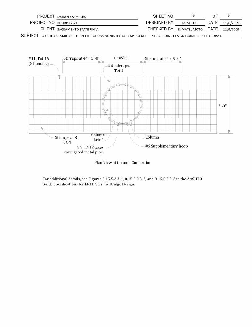
9 9
11/6/2009
DATE 11/9/2009CHECKED BY E. MATSUMOTO
DESIGNED BY SHEET NO
CLIENT NCHRP 12‐74
SUBJECT
M. STILLER DATE OF
AASHTO SEISMIC GUIDE SPECIFICATIONS NONINTEGRAL CAP POCKET BENT CAP JOINT DESIGN EXAMPLE ‐ SDCs C and D
PROJECT DESIGN EXAMPLES
PROJECT NO SACRAMENTO STATE UNIV.
Plan View at Column Connection
Dc =5'‐0"Stirrups at 4" = 5'‐0"#11, Tot 16 (8 bundles) #6 stirrups,
Tot 5
Stirrups at 4" = 5'‐0"
Stirrups at 8", UON
Column Reinf
Column
#6 Supplementary hoop
7'‐0"
54" ID 12 gage corrugated metal pipe
For additional details, see Figures 8.15.5.2.3‐1, 8.15.5.2.3‐2, and 8.15.5.2.3‐3 in the AASHTO Guide Specifications for LRFD Seismic Bridge Design.

1 12
Hybrid Bent System Design Example For SDCs C and D
Material Input Parameters
Concrete Materials (Unconfined) SGS § 8.4.4
f'c= ksi Specified 28-day compressive strength of concrete SGS Eq. 8.4.4-1
f'ce=1.3 f'c = ksi Expected concrete compressive strength
Ec= ksi Modulus of elasticity LRFD Eq. 5.4.2.4-1
Gc= ksi Shear modulus
β1= Equivalent stress block factor LRFD § 5.7.2.2
Grout Materials BCS § 8.13.8.3.2
f'cg= ksi Specified compressive strength of bedding layer BCS Eq. 8.13.8.3.2a
Check: f'cg (ksi) ≥ max[1.25(f'ce+0.5), 6.0] Limit = ksi O.K.
Joint grout shall have a 3 lb per cy fraction of polypropylene fibers for joint integrity BCS § 8.13.8.3.5a
Mild Reinforcing Steel SGS § 8.4.2
fy= ksi Specified yield stress SGS Tbl. 8.4.2-1
fye= ksi Expected yield stress SGS Tbl. 8.4.2-1
fue= ksi Expected ultimate tensile strength SGS Tbl. 8.4.2-1
Es= ksi Modulus of elasticity SGS Tbl. 8.4.2-1
εy= Effective yield strain SGS Tbl. 8.4.2-1
εsu= Ultimate tensile strain SGS Tbl. 8.4.2-1
εRsu= Reduced ultimate tensile strain accounting for bar bending SGS § 8.4.2
fyh= ksi Specified minimum yield stress of confining hoops
Post-Tensioning Steel SGS § 8.4.3
Eps= ksi Modulus of elasticity SGS Eq. 8.4.3-3
fpu= ksi Specified ultimate tensile strength SGS § 8.4.3
εps,EE= Essentially elastic prestress strain SGS § 8.4.3
PROJECT DESIGN EXAMPLES SHEET NO OF
CLIENT UNIVERSITY OF CALIFORNIA SAN DIEGO CHECKED BY Restrepo, JI DATE 12/31/2009
PROJECT NO NCHRP 12-74 DESIGNED BY Tobolski, MJ DATE 12/31/2009
68
60
60
AASHTO LRFD
Bridge Design
Specifications
(LRFD)
4372
270
0.009
95
0.06
28500
This design example is developed to show a practitioner a methodology to design a multi-column hybrid
precast bridge column system. Complete development of simplified lateral force-displacement predictions
are presented. This includes the estimatation of the effective yield point and the ultimate point for lateral
response. The procedure presented requires itteration of the column neutral axis depth at both limit
states that can be easily accomodated with modern computer software.
A lateral demand analysis is conducted for a bridge located in a region of high seismic demand. The
developed lateral properties are used to determing the effective initial strucutural period for the
development of lateral seismic demands. The short-period displacement modification factor from
AASHTO are used to account for potential amplification of displacement demands at low periods.
The calculated flexural capacity is used to investigate the required seismic design required for the precast bent
cap. Demands on the bent cap joint are investigated to determine the required detailing within the joint
region.
7.1
0.12
SUBJECT AASHTO SEISMIC GUIDE SPECIFICATIONS HYBRID BENT CAP JOINT DESIGN EXAMPLE - SDCs C and D
AASHTO LRFD
Bridge
Construction
Specifications
(BCS)
4.0
5.2
8.0
AASHTO
Guide
Specifications
for LRFD
Seismic
Bridge Design
(SGS)
1749
0.79
29000
0.002

2 12PROJECT DESIGN EXAMPLES SHEET NO OF
CLIENT UNIVERSITY OF CALIFORNIA SAN DIEGO CHECKED BY Restrepo, JI DATE 12/31/2009
PROJECT NO NCHRP 12-74 DESIGNED BY Tobolski, MJ DATE 12/31/2009
SUBJECT AASHTO SEISMIC GUIDE SPECIFICATIONS HYBRID BENT CAP JOINT DESIGN EXAMPLE - SDCs C and D
fps,EE= ksi Essentially elastic prestress stress
εRps,u= Reduced ultimate prestress strain SGS § 8.4.3
Geometric Input Parameters
Column Dimensions
Dc= ft Gross column diameter
dps= in Distance from edge of column to tendon centerline
cc= in Clear cover to hoop reinforcement
Ag= ft2Gross column section area
Ae= ft2Effective column shear area SGS Eq. 8.6.2-2
Ig= ft4Gross column moment of inertia
Hclr= ft Clear height of column
H= ft Height from centerline bent cap to centerline foundation
nj= = 1 if fixed-pinned ; = 2 if fixed-fixed
Hinf= ft Distance to point of inflection
Lps= ft Total length (unbonded) of post-tensioning tendon
N= kip Total gravity force acting during seismic loading (including overturning)
N / f'ceAg = % Gravity load axial load ratio
Bent Cap Dimension
Bcap= ft Bent cap width
Ds= ft Bent cap height
Column Transverse Reinforcement Specified
Size of bars: Butt-welded hoop reinforcement
dbar= in Diameter of reinforcing bar
Av= in2Area of reinforcing bar
shoop= in Center-to-center spacing of hoops
D'= ft Diameter of confined concrete core
Acc= ft2Area of confined concrete core
ρs= 4 Av/[D's] = % Volumetric ratio of confinement reinforcement SGS Eq. 8.6.2-6
Reinforcement Input Parameters
Column Mild Reinforcement Specified
Number of bars: Size of bars:
dbar= in Diameter of reinforcing bar
Abar= in2Area of reinforcing bar
As= in2Total area of mild reinforcement
ρs= % Volumetric ratio of mild reinforcement
Dbars= ft Diameter about which bars are distributed
sb= in Clear spacing of reinforcing bars
Recommended: sb < 8.00 inches: 8.17 < 8.00, O.K. SGS § 8.6.3
565
6.00
9.6
0.53
0.44
4
3.60
10.20
12.57
2.0
245
0.03
12.57
4.0
8.17
3.47
No. 6
0.75
2
9.5
10.05
5.0
4.5
16 No. 7
0.88
0.60
19.0
26.5
24.0
1.02
24.0

3 12PROJECT DESIGN EXAMPLES SHEET NO OF
CLIENT UNIVERSITY OF CALIFORNIA SAN DIEGO CHECKED BY Restrepo, JI DATE 12/31/2009
PROJECT NO NCHRP 12-74 DESIGNED BY Tobolski, MJ DATE 12/31/2009
SUBJECT AASHTO SEISMIC GUIDE SPECIFICATIONS HYBRID BENT CAP JOINT DESIGN EXAMPLE - SDCs C and D
Column Post-Tensioning Specified
Number of tendons: Number of strands per tendon:
Diamter of strands: in Area of single strand: in2
Aps= in2
fpse / fpu = Effective post-tensioning stress ratio
Aps fpse / f'ce Ag = %
Confined Concrete Properties (based on specified reinforcement)
ρcc= As / Acc = % Volumetric ratio of mild reinforcement with respect to core
ρs= 4 Av/[D's] = % Volumetric ratio of confinement reinforcement SGS Eq. 8.6.2-6
ke= [1-0.5s/D']2/[1-ρcc]= Confinement effectiveness coefficient
flp= ke ρs fyh / 2 = ksi Effective confining stress
f'cce= ksi Expected confined concrete compressive strength
εcc= Compressive strain at peak stress
εcu= Ultimate confined concrete compressive strain
εcu / εcc = K = f'cce / f'ce =
from Park and
Paulay
Figure 3.8
βc= Confined concrete equivalent stress block depth factor
αccβcc=
αcc= Confined concrete equivalent stress block stress factor
4.48
1 12
0.6 0.217
2.60
0.60
1.33
0.98
0.91
0.65
1.02
0.916
0.28
6.92
0.019
0.005
3.55
0.89

4 12PROJECT DESIGN EXAMPLES SHEET NO OF
CLIENT UNIVERSITY OF CALIFORNIA SAN DIEGO CHECKED BY Restrepo, JI DATE 12/31/2009
PROJECT NO NCHRP 12-74 DESIGNED BY Tobolski, MJ DATE 12/31/2009
SUBJECT AASHTO SEISMIC GUIDE SPECIFICATIONS HYBRID BENT CAP JOINT DESIGN EXAMPLE - SDCs C and D
Reference Yield Point
c = in Neutral axis depth (determined via numerical solver)
c / Dc= %
θconc= cos-1{[0.5D-β1c]/[0.5D]} = deg = rad
θsteel= cos-1{[0.5D-c]/[0.5D]} = deg = rad
Tps,y= Apsfpse Tension force in post-tensioning
Ts,y= Asfy{[π-θsteel]/π} Resultant tension force in mild reinforcement
Cs,y= Asfyθsteel/π Resultant compression force in mild reinforcement
Cc,y=0.85f'ceD2[θconc-sin(θconc)cos(θconc)]/4 Resultant compression force in concrete
Tps,y= kip Post-tensioning
Ts,y= kip Mild reinforcement Cs,y= kip Mild reinforcement
N= kip Axial load Cc,y= kip Concrete
ΣT= kip ΣC= kip
ΣT = ΣC = Equilibrium satisfied
yst= 0.5Dbarssin(π-θsteel)/[π-θsteel] = in Resultant steel tension eccentricity
ysc= 0.5Dbarssin(π-θsteel)/[π-θsteel] = in Resultant steel compression eccentricity
yc= Dsin(θconc)3/{3[θconc-sin(θconc)cos(θconc)]}= in Resultant concrete compression eccentricity
My= Cc,yyc+Cs,yysc+Ts,yyst = kip-ft Reference yield moment
Vy= My / Hinf = kip Reference yield base shear
θb,y= 2εyLub/[D-Dbars-2c] = % Fixed end rotation at joint due to opening
∆f= VyHclr3/[3nj
2EcIg] = in Deformation due to elastic bending of column
∆v= VyHclr/[GcAcs] = in Deformation due to shear deformations of column
∆j= θb,yHclr = in Deformation due to fixed end rotation due to opening
∆y= in Total Deformation
DR= % Drift ratio
8.19
17.50
18.03
2445
257
0.09
0.22
0.02
0.20
0.45
0.20
565
1431 1431
26.6
Tension / Axial Force Summation Compression Force Summation
12.78
422
54.6
1431 1431
0.9529
1.0014Use radians for all equations
57.4
445 208
1224

5 12PROJECT DESIGN EXAMPLES SHEET NO OF
CLIENT UNIVERSITY OF CALIFORNIA SAN DIEGO CHECKED BY Restrepo, JI DATE 12/31/2009
PROJECT NO NCHRP 12-74 DESIGNED BY Tobolski, MJ DATE 12/31/2009
SUBJECT AASHTO SEISMIC GUIDE SPECIFICATIONS HYBRID BENT CAP JOINT DESIGN EXAMPLE - SDCs C and D
Ultimate Point
c = in Neutral axis depth (determined via numerical solver)
c / Dc= %
c / Dc < 25% < O.K. SGS Eq. 8.8.1-4
θconc= cos-1{[0.5D'-βccc]/[0.5D']} = deg = rad
αut= 0.8 - 0.35 c/Dbars = Shape factor for ultimate tension force in mild reinforcement
αuc= 0.05 + 0.4 c/Dbars = Shape factor for ultimate compression force in mild reinforcement
ψut= 0.1 + 0.24 c/Dbars = Shape factor for location of resultant tension force
ψuc= 0.5 - 0.16 c/Dbars = Shape factor for location of resultant compression force
Tps,u= Aps[fpse+θb,uEps[dps-cc-c]/Lps Tension force in post-tensioning
Ts,u= Asfuαut Resultant tension force in mild reinforcement
Cs,y= Asfuαuc Resultant compression force in mild reinforcement
Cc,y=αccf'ccD'2[θconc-sin(θconc)cos(θconc)]/4 Resultant compression force in concrete
Tps,u= kip Post-tensioning
Ts,u= kip Mild reinforcement Cs,u= kip Mild reinforcement
N= kip Axial load Cc,u= kip Concrete
ΣT= kip ΣC= kip
ΣT = ΣC /= Force imbalance, adjust c
yst= ψutDbars = in Resultant steel tension eccentricity
ysc= ψucDbars = in Resultant steel compression eccentricity
yc= D'sin(θconc)3/{3[θconc-sin(θconc)cos(θconc)]}= in Resultant concrete compression eccentricity
Mu= Cc,uyc+Cs,uysc+Ts,uyst = kip-ft Ultimate moment strength
Vu= Mu / Hinf = kip Ultimate shear strength
θb,u= εcu % Fixed end rotation at joint due to opening
∆f= VuHclr3/[3nj
2EcIg] = in Deformation due to elastic bending of column
∆v= VuHclr/[GcAcs] = in Deformation due to shear deformations of column
∆j= θb,uHclr = in Deformation due to fixed end rotation due to opening
∆u= in Total Deformation
DR= % Drift ratio
15.73
2677
0.72
0.14
0.16
0.46
1.88
282
0.24
0.03
4.29
4.56
2.00
529
654
Compression Force Summation
131
565 1611
1748 1742
6.51
19.24
9.80
20.4
57.4
Tension / Axial Force Summation
20.41 25.00
1.0019
1748 1742

6 12PROJECT DESIGN EXAMPLES SHEET NO OF
CLIENT UNIVERSITY OF CALIFORNIA SAN DIEGO CHECKED BY Restrepo, JI DATE 12/31/2009
PROJECT NO NCHRP 12-74 DESIGNED BY Tobolski, MJ DATE 12/31/2009
SUBJECT AASHTO SEISMIC GUIDE SPECIFICATIONS HYBRID BENT CAP JOINT DESIGN EXAMPLE - SDCs C and D
Performance Requirements
fps/fpu= Post-tensioning stress ratio at ultimate point
fps/fpu < fps,EE/fpu < O.K.
Lub,min= in Minimum required unbonded length of mild reinforcement
Lub= in Specified unbonded length of mild reinforcement
0.5Dc > Lub > Lub,min >= >= O.K. SGS § 8.8.14
βM,y= Contribution of mild reinforcement to reference moment strength
0.33 > βM,y > 0.20 >= >= O.K. SGS Eq. 8.8.1-3
8.8.2-5
βM,u= Contribution of mild reinforcement to ultimate moment strength
βPT= Effective axial load divided by tensile steel force at ultimate point
βPT=(0.9N+Tps,y)/Ts,u > 1 > O.K. SGS Eq. 8.8.1-2
Response Summary
∆y= in
DRy= %
Vy= kip
My= kip
∆C= in
DRu= %
Vu= kip
Mu= kip
ki= kip/in
kpe= kip/in
αpe= %
µ∆,c=
W = N = kip
T= sec
Seismic Demand Analysis
SS= g 0.2 second spectral acceleration (MCE)
S1= g 1.0 second spectral acceleration (MCE)
Site Class: D Soil site class SGS § 3.4.2.1
Fa= Site coefficient for 0.2 second period spectral acceleration SGS § 3.4.2.3
Fv= Site coefficient for 1.0 second period spectral acceleration SGS § 3.4.2.3
SDS= g Design 0.2 second spectral acceleration SGS Eq. 3.4.1-1
SD1= g Design 1.0 second spectral acceleration SGS Eq. 3.4.1-2
6
1.03
565
0.32
10.2
1.50
0.75 0.91
12.00 9.98
0.25 0.20
1.42 1.00
0.33
24.00
1.42
0.21
9.98
0.75
12.00
0.25
257
0.45
0.20
2445
4.56
2.00
282
2677
576
0.55
1.00
1.50
1.50
0.83
0
500
1000
1500
2000
2500
3000
0.00 0.50 1.00 1.50 2.00 2.50
Mo
me
nt,
kip
-ft
Drift Ratio, %

7 12PROJECT DESIGN EXAMPLES SHEET NO OF
CLIENT UNIVERSITY OF CALIFORNIA SAN DIEGO CHECKED BY Restrepo, JI DATE 12/31/2009
PROJECT NO NCHRP 12-74 DESIGNED BY Tobolski, MJ DATE 12/31/2009
SUBJECT AASHTO SEISMIC GUIDE SPECIFICATIONS HYBRID BENT CAP JOINT DESIGN EXAMPLE - SDCs C and D
Seismic Design Category D SGS § 4
TS= sec Response spectrum upper bound corner period SGS Eq. 3.4.1-5
To= sec Response spectrum lower bound corner period SGS Eq. 3.4.1-4
T*= sec Characteristic ground motion period SGS Eq. 4.3.3-3
Sa= g Design spectral acceleration SGS § 3.4.1
∆D= in ∆D= in ∆D= in ∆D= in
µ∆,D= µ∆,D= µ∆,D= µ∆,D= SGS Eq. 4.9-5
Rd= Rd= Rd= Rd= <- Converged SGS Eq. 4.3.3-1/2
∆D < ∆C < Demand less than capacity, O.K. SGS Eq. 4.8-1
µ∆,D < 6 > Ductility demand greater than limit, NO GOOD SGS § 4.9
MP-∆= kip-ft P-∆ moment demand based un seismic dispalcement demand
MP-∆ < 0.25 x Mu < O.K. SGS Eq. 4.11.5-1
Joint Performance SGS § 8.15.1
Note:
Mp=MuH/Hclr = kip-ft Effective ultimate moment capacity at CL bent cap
Mpo = λmo Mp SGS § 9
λmo = 1.2 (ASTM A706) SGS Eq. 8.5-1
Mpo = kip-ft Overstrength moment demand acting on bent cap
Ascap
top = in2
Ascap
bot = in2
669
4.56
Trial 1 Trial 2 Trial 3 Trial 4
Required longitudinal reinforcement required
per design requirements of Extreme I load case
2.91
6.51
Moment resisting connections are designed to transmit the maximum forces produced when the
column reaches its overstrength moment capacity, Mpo.
Capacity of the bent cap section needs to satisfy applicable load combinations, including the
Strength load cases and capacity protection during Extreme Event load cases. The bent cap
section capacity is not investigated in this design example.
3382
4058
16.55
12.92
2.93
138
138
1.47
1.82
3.29
0.55
1.50
0.11
0.69
6.56 6.00
1.99
2.93
6.56
1.99
2.67
5.98
1.98

8 12PROJECT DESIGN EXAMPLES SHEET NO OF
CLIENT UNIVERSITY OF CALIFORNIA SAN DIEGO CHECKED BY Restrepo, JI DATE 12/31/2009
PROJECT NO NCHRP 12-74 DESIGNED BY Tobolski, MJ DATE 12/31/2009
SUBJECT AASHTO SEISMIC GUIDE SPECIFICATIONS HYBRID BENT CAP JOINT DESIGN EXAMPLE - SDCs C and D
Joint Proportioning SGS § 8.15.2
Principal Stresses
Principal stresses in the joint are limited by the following equations:
Principal compression, pc : pc ≤ 0.25 f'ce = ksi maximum SGS Eq. 8.15.2.1-1
Principal tension, pt : pt ≤ 0.38 √f'ce = ksi maximum SGS Eq. 8.15.2.1-2
Bcap = in
Dc = in
Ds = in
lac = in Note 1
Pc = kips Includes effective PT
Pb = kips Note 2
h = ft Note 3Mpo = kip-ft Note 3
Notes:
1)
2) No prestressing in section.
3)
pt = = ksi Principal tension stress in joint SGS Eq. 8.15.2.1-3
pc = = ksi Principal compression stress in joint SGS Eq. 8.15.2.1-4
Tc = Ts,u = kips Column tensile force at ultimate (from analysis above) SGS § 8.15.2
Ajv = lac Bcap = in2Vertical joint area SGS Eq. 8.15.2.1-6
vjv = Tc / Ajv = ksi Vertical joint shear stress Eq. 8.15.2.1-5
Ajh = (Dc + Ds) Bcap = in2Horizontal joint area SGS Eq. 8.15.2.1-8
fv = Pc / Ajh = ksi Vertical joint shear stress SGS Eq. 8.15.2.1-7
fh = Pb / (Bcap Ds) = ksi Horizontal joint stress SGS Eq. 8.15.2.1-9
pc = ksi ≤ ksi maximum OK
pt = ksi ≤ ksi maximum OK
0.309
987
0.0
654
0.309 1.30 Joint proportions are acceptable based
on principal stress requirements.0.148
0.148
0
2.184058
Length of column longitudinal rebar extended
into cap. See calculations below.
Determined from sectional analysis. Tension
in column longitudinal rebar may also be
derived from sectional analysis.
51.0
1.30
0.87
60.0
48.0
54.0
0.87
0.214
3060.0
0.1612
6120
fh + fv
2+ fh - fv
2+ v2
jv
2
fh + fv
2- fh - fv
2+ v2
jv
2
fh fh
fv
fv
vjv
vjv
vjh
vjh
Pc
Vocol
Mbleft
Tc Cc
Vbleft
Tbleft
Cbleft
Mbright
Vbright
Tbright
Cbright
Bcap
Ds
Dc
Mpocol

9 12PROJECT DESIGN EXAMPLES SHEET NO OF
CLIENT UNIVERSITY OF CALIFORNIA SAN DIEGO CHECKED BY Restrepo, JI DATE 12/31/2009
PROJECT NO NCHRP 12-74 DESIGNED BY Tobolski, MJ DATE 12/31/2009
SUBJECT AASHTO SEISMIC GUIDE SPECIFICATIONS HYBRID BENT CAP JOINT DESIGN EXAMPLE - SDCs C and D
Minimum Development Length of Column Longitudinal Reinforcement SGS § 8.15.2.2
lac ≥ 2 dbl fye dbl = in No. 7
fye = ksi SGS Eq. 8.15.2.2.2-1
f'cg = ksi = min (7.5 ksi, 7.0 ksi) per Article 8.15.2.2.2
lac = in (minimum)
lac = Ds - 3"= in
in ≥ in (minimum) OK Extend to top face of cap less 3 in cover.
Minimum Joint Shear Reinforcing for Precast Bent Cap Connections SGS § 8.15.3
Check if principal tension, pt, is ≥ 0.11√f'ce (condition for likely joint cracking)
Calculated tension = ksi
Limit, 0.11√ f'ce = ksi
pt = ksi ≤ ksi limit
Calculate required volumetric ratio of transverse joint reinforcement:
ρs ≥ 0.11 √f'ce / fyh = Ast = in2SGS Eq. 8.15.3.1-1
lac = in
ρs =
Asp = in2(#6 hoop)
D' = in (confined diameter of column between centroids of hoop)
s = in
f'cg
0.88
68
7.0
17.1
Extend column reinforcement as far as practically possible; assume 3" clear from opposite face,
per Article 8.15.2.2.2.
0.148 0.251
9.6
51.0
0.0037
51.0
51.0 17.1
Where principal tension in the joint is greater than or equal to 0.11√ f'c and joint proportioning is
acceptable per Article 8.15.2, additional transverse joint reinforcement for cap pocket connections
per Article 8.15.5.2.3 is to be added, and Eqs. 8.15.3.1-1 and 8.15.3.1-2 are to be satisfied.
0.148
0.251
For this HYBRID DESIGN EXAMPLE, only minimum transverse reinforcement is required. Due to the
use of a combination of both post-tensioning and mild reinforcement, it is common for the principal
tensile stress in the joint to be below the condition for likely joint cracking. For an example
calculation with full joint detailing, see GROUTED DUCT DESIGN EXAMPLE FOR SDC C and D.
Only transverse reinforcement per SGS Eq. 8.15.3.1-1 is
required. No additional joint reinforcement is required
Assume transverse reinforcement in the joint is the same size as the column plastic hinging region
transverse reinforcement.
0.44
43.25
8.0 (trial spacing of transverse reinforcement hoops; spacing not
to exceed 12" or 0.3Ds per Art. 8.15.3.2.1)
4Asp
D'gd s

10 12PROJECT DESIGN EXAMPLES SHEET NO OF
CLIENT UNIVERSITY OF CALIFORNIA SAN DIEGO CHECKED BY Restrepo, JI DATE 12/31/2009
PROJECT NO NCHRP 12-74 DESIGNED BY Tobolski, MJ DATE 12/31/2009
SUBJECT AASHTO SEISMIC GUIDE SPECIFICATIONS HYBRID BENT CAP JOINT DESIGN EXAMPLE - SDCs C and D
D'gd =
D'gd = in
(deformed diameters are used for clearance calculations)
ρs =
ρs = ≥ minimum OK
Note, must also check bursting requirements at post-tensioning anchorage per LRFD §5.10.9.6.3
Vertical Stirrups Inside the Joint Region SGS § 8.15.3.2
Asjvi ≥ 0.10 Ast Required area of vertical stirrups spaced evenly over a length equal to Dc SGS Eq. 8.14.5.2.2a-1
Ast = in2
Asjvi ≥ in2 spaced over ft
Use (2) #6 double leg stirrups spaced evenly inside joint region.
Asjvi = 2 2 in2
>= in2 O.K.
Bedding Layer Reinforcement SGS
8.15.5.2.1
Provide bedding layer transverse reinforcement to match the size and type used in the column
plastic hinging region (#6 bar). Hoop will be placed at mid-height in the bedding layer; bedding
layer to be 3" thick. Cover on top column hoop to be 2" as shown in figures below, and resulting
center-to-center spacing of transverse reinforcement is 4" throughout, in accordance with
Article 8.8.14.
Column diameter - 2 x clear cover - hoop diameter - long.
column reinf diameter + grouted duct inside diameter +
corrugation amplitude x 2.
46.61
0.0047
0.0047 0.0037 8" spacing is adequate (Note: The common practice
for cast-in-place construction to carry hoop spacing
from column into cap is not expected for precast bent
caps as cages are built independently)
9.6
0.96 4.0
0.44locations x legs / location x 1.76 0.96in2 / leg =
D'gd
Grouted Duct
Column Reinf.
Column
Hoop
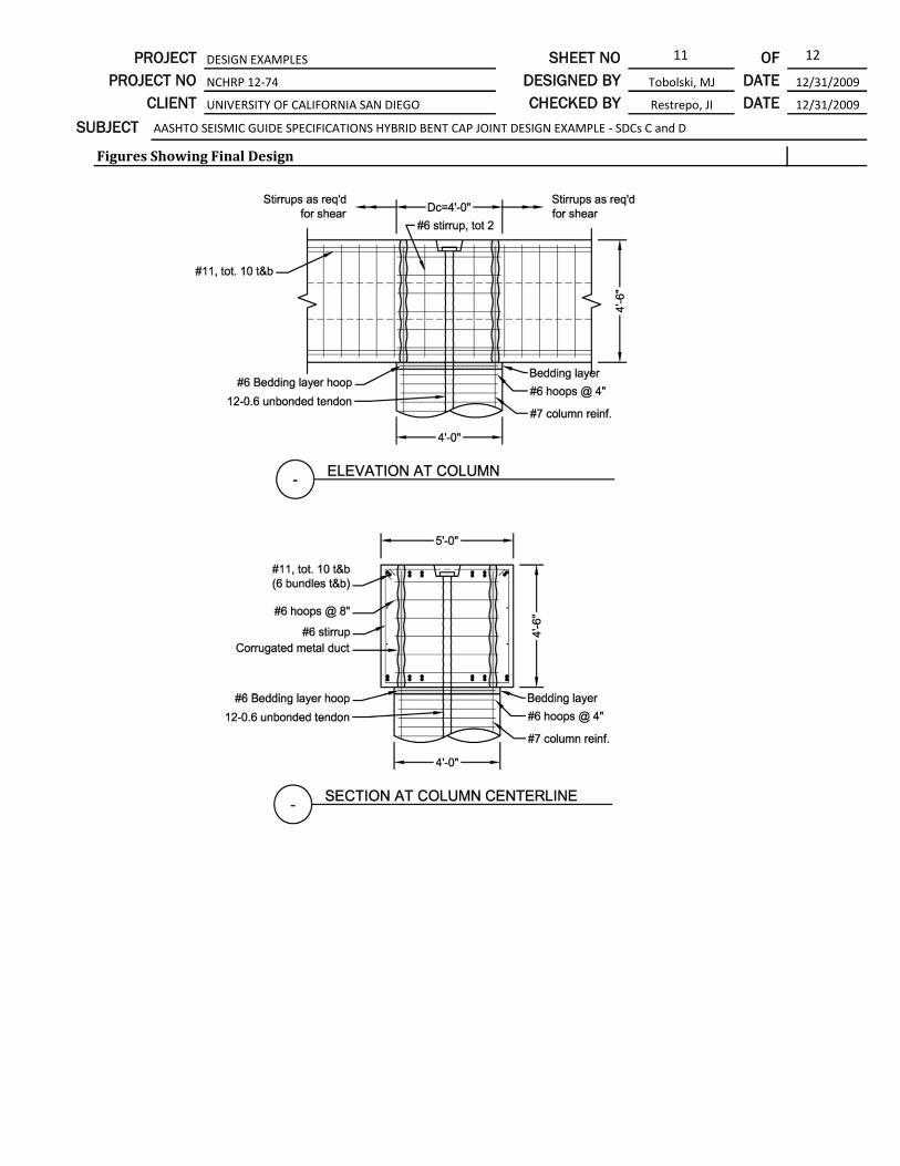
11 12PROJECT DESIGN EXAMPLES SHEET NO OF
CLIENT UNIVERSITY OF CALIFORNIA SAN DIEGO CHECKED BY Restrepo, JI DATE 12/31/2009
PROJECT NO NCHRP 12-74 DESIGNED BY Tobolski, MJ DATE 12/31/2009
SUBJECT AASHTO SEISMIC GUIDE SPECIFICATIONS HYBRID BENT CAP JOINT DESIGN EXAMPLE - SDCs C and D
Figures Showing Final Design

12 12PROJECT DESIGN EXAMPLES SHEET NO OF
CLIENT UNIVERSITY OF CALIFORNIA SAN DIEGO CHECKED BY Restrepo, JI DATE 12/31/2009
PROJECT NO NCHRP 12-74 DESIGNED BY Tobolski, MJ DATE 12/31/2009
SUBJECT AASHTO SEISMIC GUIDE SPECIFICATIONS HYBRID BENT CAP JOINT DESIGN EXAMPLE - SDCs C and D
Simplified Section at Column Edge
4" overall spacing
maintained
Clear cover may be less
than 2" per Art. 8.8.14
Bent Cap
Bedding
Layer
Column
1.5"
2.5"
per Art. 8.15.5.2.1
per Art. 8.8.14

1 15
Integral Bent Cap Design Example for SDC C and D
Material Input Parameters
Concrete Materials (Unconfined) SGS § 8.4.4
f'c= ksi Specified 28-day compressive strength of column concrete SGS Eq. 8.4.4-1
f'ce=1.3 f'c = ksi Expected column concrete compressive strength
f'cg= ksi Specified 28-day compressive strength of girder concrete
Grout Materials BCS § 8.13.8.3.2
f'cgb= ksi Specified compressive strength of grout bedding layer
Check: f'cgb (ksi) ≥ max[1.25(f'ce)+0.5, 6.0)] BCS Eq. 8.13.8.3.2a
ksi >= ksi O.K.
f'cgv= ksi Specified compressive strength of grout closure joint
Check: f'cgv (ksi) ≥ max[1.25(f'cg)+0.5, 6.0)] BCS § 8.13.8.3.1
ksi >= ksi O.K.
Closure joint grout shall have a 3 lb per cy fraction of polypropylene fibers for joint integrity BCS § 8.13.8.3.6a
Mild Reinforcing Steel SGS § 8.4.2
fy= ksi Specified yield stress SGS Tbl. 8.4.2-1
fye= ksi Expected yield stress SGS Tbl. 8.4.2-1
fue= ksi Expected tensile strength SGS Tbl. 8.4.2-1
Es= ksi Modulus of elasticity SGS Tbl. 8.4.2-1
εy= Effective yield strain SGS Tbl. 8.4.2-1
εRsu= Reduced ultimate tensile strain
fyh= ksi Specified yield stress of confining hoops60
0.09
0.002
68
60
95
8.0 7.0
8.0
8.0 8.0
PROJECT DESIGN EXAMPLES SHEET NO OF
CLIENT UNIVERSITY OF CALIFORNIA SAN DIEGO CHECKED BY Restrepo, JI DATE 12/31/2009
PROJECT NO NCHRP 12-74 DESIGNED BY Tobolski, MJ DATE 12/31/2009
SUBJECT AASHTO SEISMIC GUIDE SPECIFICATIONS INTEGRAL BENT CAP DESIGN EXAMPLE - SDCs C and D
AASHTO
Guide
Specifications
for LRFD
Seismic
Bridge Design
(SGS)
6.0
4.0
5.2
8.0
29000
This design example provides practitioners with a comprehensive example of the design activties
required to design the integral, precast bent cap system presented in NCHRP 12-74. This structural
system is developed for use in high seismic regions where the advantages of integral superstructure
response may be desirable.
In this example, the integral connection between the superstructure and bent cap is made through post-
tensioned spliced girders, which are discontinuous at the bent cap. Flexural continuity is provided
through the splicing of girders through the bent cap using post-tensioning tendons. This structural type
and seismic response was validated through experimental work under the NCHRP 12-74 project.
The connection between the bent cap and column is made through a grouted duct connection. This
connection type was validated for high seismic regions under the NCHRP 12-74 project. The applicable
commentary sections in the AASHTO Guide Specifications for LRFD Seismic Bridge Design (SGS) provide
additional background.
AASHTO LRFD
Bridge
Construction
Specifications
(BCS)
AASHTO LRFD
Bridge Design
Specifications
(LRFD)
Bedding Layer

2 15PROJECT DESIGN EXAMPLES SHEET NO OF
CLIENT UNIVERSITY OF CALIFORNIA SAN DIEGO CHECKED BY Restrepo, JI DATE 12/31/2009
PROJECT NO NCHRP 12-74 DESIGNED BY Tobolski, MJ DATE 12/31/2009
SUBJECT AASHTO SEISMIC GUIDE SPECIFICATIONS INTEGRAL BENT CAP DESIGN EXAMPLE - SDCs C and D
Geometric Input Parameters
Column Dimensions
Dc= ft Gross column diameter
Hclr= ft Clear height of column
H= ft Clear height to point of contraflexure (fixed-fixed column)
Lp= in Idealized plastic hinge length
Lp/Dc= Normalized plastic hinge length
L= ft Span length between centerline of bents
Column reinforcement
(20) No. 11 A706 Reinforcing Bars
As,bar = in2
Ast= in2
Superstructure Dimensions
Superstructure consists of 72 inch tall post-tensioned girders with local end blocks at bent
Dgirder= in Depth of post-tensioned girder
Dhaunch= in Thickness of girder haunch (specified)
Ddeck= in Thickness of reinforced concrete deck
Ds= ft Total depth of superstructure (in longitudinal direction)
sg= ft Girder center-to-center spacing
ApsTop= in2
fpeTop= ksi Top tendon details (12-0.6" at 60% GUTS)
ApsMid= in2
fpeMid= ksi Middle tendon details (12-0.6" at 60% GUTS)
ApsBot= in2
fpeBot= ksi Bottom tendon details (7-0.6" unstressed)
0.465
9.00
2.604
2.604
1.519
162
162
0
11.0
1.56
31.2
140
5.0
22.0
27.9
74.0
2.0
8.0
7.00

3 15PROJECT DESIGN EXAMPLES SHEET NO OF
CLIENT UNIVERSITY OF CALIFORNIA SAN DIEGO CHECKED BY Restrepo, JI DATE 12/31/2009
PROJECT NO NCHRP 12-74 DESIGNED BY Tobolski, MJ DATE 12/31/2009
SUBJECT AASHTO SEISMIC GUIDE SPECIFICATIONS INTEGRAL BENT CAP DESIGN EXAMPLE - SDCs C and D
wcj= in Specified closure joint dimension
Check: wcj ≤ 3" for grout closure joints BCS § 8.13.8.3.6a
in <= in O.K.
Bent Cap Dimension
Bcap= ft Bent cap width
hextra= in Additional depth of precast cap below girder (for splicing)
DP/C= ft Bent cap height
Dcap= ft Total depth of bent cap including deck
AsTop= in2
fpeTop= ksi (10) No. 11 reinforcing bars
AsBot= in2
fpeMid= ksi (8) No. 11 reinforcing bars
ApsBC= in2
fpeMid= ksi Middle tendon details (12-0.6" at 60% GUTS)
Seismic Demands
Note:
2.0
2.0 3.0
NOTE: For larger closure joints, concrete shall replace grout material and joint shall be
reinforced to ensure the integrity of the concrete is maintained when the joint opens.
The focus of this design example is on detailing of the bent cap and superstructure. Traditional
seismic displacement checks, etc. shall be carried out but are not included herein.
7.0
6.67
6.0
Moment resisting connections are designed to transmit the maximum forces produced when the
column reaches its overstrength moment capacity, Mpo.
Determine the idealized plastic moment capacity of the column, Mp, using a sectional analysis
program, and calculate the overstrength moment capacity, Mpo, per Article 8.5.
162
7.50
15.6 162
12.48 162
9.11
Capacity of the bent cap section needs to satisfy applicable load combinations, including the
Strength load cases and capacity protection during Extreme Event load cases. The bent cap
section capacity is not investigated in this design example.

4 15PROJECT DESIGN EXAMPLES SHEET NO OF
CLIENT UNIVERSITY OF CALIFORNIA SAN DIEGO CHECKED BY Restrepo, JI DATE 12/31/2009
PROJECT NO NCHRP 12-74 DESIGNED BY Tobolski, MJ DATE 12/31/2009
SUBJECT AASHTO SEISMIC GUIDE SPECIFICATIONS INTEGRAL BENT CAP DESIGN EXAMPLE - SDCs C and D
Axial load acting on column per extreme event load case = kips (Pc)
f'ce (expected concrete compressive strength) = 1.3 x f'c = 5.2 ksi SGS
fye (expected steel yield strength) = 68 ksi (column bars) 8.4.4
Ast = in2Total area of column reinforcement
Mp = kip-ft Idealized bending moment capacity (from moment-curvature) SGS § 8.5
Mpo = λmo Mp
λmo = 1.2 (ASTM A706) SGS Eq. 8.5-1
Mpo = kip-ft Overstrength bending moment capacity of column (at critical section)
Vpo = Mpo / H = kip-ft Overstrength shear demand from column plastic hinge
Mpo,cap = Vpo x [H + 0.5 Dcap ] = kip-ft Overstrength bending moment demand at superstruct.
Superstructure Capacity Design for Longitudinal Direction for SDC C and D SGS § 8.10
Seismic Moment Capacity of Superstructure
Beff = ft Effective width of superstructure (open soffit, girder-deck system) SGS Eq. 8.10-2
Beff will capture (2) girder webs. Perform moment-curvature on superstructure with (2) girders
From moment-curvature analysis:
Nominal Bending Moment Capacity
Mne+ = kip-ft
Mne- = kip-ft
Ultimate Curvature Capacity
Sample sectional analysis input image φu+ = 1/ft
φu- = 1/ft
NOTE: Details of moment-curvature not shown
Maximum Extreme Event I Demands Acting on 2 Girders from Plastic Hinging
Design actions acting on 2 girders
γDMD= kip-ft γVD= kip Factored dead load demand
0.5 MLL,min= kip-ft 0.5 VLL,min= kip Factored live load for seismic design
0.5 MLL,max= kip-ft 0.5 VLL,max= kip Factored live load for seismic design
PGAh = g Horizontal peak ground acceleration
V / H = Vertical to horizontal spectral acceleration ratio for zero period acceleration
Based on Bozorgnia and Campbell (2004)
PGAv = g Vertical peak ground acceleration
715
10540
The superstructure shall be designed as a capacity protected member. Flexural capacity of the section
shall be determined via moment-curvature analysis per SGS §8.5
12.0
8975
-13015
-2248
415
90
414 -10
825.0
6550
7860
31.2
-850
6.641E-03
-4.940E-03
0.60
1.00
0.60

5 15PROJECT DESIGN EXAMPLES SHEET NO OF
CLIENT UNIVERSITY OF CALIFORNIA SAN DIEGO CHECKED BY Restrepo, JI DATE 12/31/2009
PROJECT NO NCHRP 12-74 DESIGNED BY Tobolski, MJ DATE 12/31/2009
SUBJECT AASHTO SEISMIC GUIDE SPECIFICATIONS INTEGRAL BENT CAP DESIGN EXAMPLE - SDCs C and D
ME,v = [ PGAv VD / L ] L2 / 12 = kip-ft Seismic moment demand from vertical
VE,v = PGAv VD = kip Seismic shear demand from vertical
MEEI,min= kip-ft >= Mne- = kip-ft O.K.
MEEI,max= kip-ft <= Mne+ = kip-ft O.K.
Superstructure Rotation Capacity
φu = 1/ft Limiting superstructure curvature capacity from moment-curvature
Lp,s=Ds/2 = ft Superstructure effective hinge length SGS Eq. 4.11.6.2-1
θu = rad Limiting superstructure rotation capacity
Check: θu >= 0.01 rad θu = rad >= O.K. SGS § 8.10.3
∆settle=θu L = in Permissible relative settlement between bents
SGS § 8.10.5
Seismic Shear Capacity across Closure Joint
VEEI+= kip Maximum vertical shear acting on single girder
NPT= kip Effective beam post-tensioning force
µ = Shear friction coefficient
φ = Strength reduction factor for shear LRFD § 5.5.4.2
φVn = φ µ NPT = kip
VEEI+= kip <= φVn = kip O.K.
Seismic Shear Capacity at Girder End
Investigate seismic shear capacity during joint opening for design of hanger bars
VEEI+= kip Vertical shear acting on single girder during maximum positive flexure
VEEI+= kip Vertical shear acting on single girder during maximum negative flexure
Place shear reinforcement based on a 30d fan considering shear depth equal to neutral axis depth
c = in Neutral axis depth at nominal moment capacity (from moment-curvature)
φ = Strength reduction factor for shear
As,req = in2Minimum required area of shear reinforcement
length = in Distance over which shear reinforcement shall be placed
-10692
7158
-13015
8975
4.940E-03
3.5
170
390
0.9
8.13
3.15
14.08
2324
199
0.017
29.0
0.017 0.010
Closed hoops shall be placed in the bottom flange of the precast girder spaced with the vertical
shear reinforcement, not to exceed 8" spacing. Closed hoops shall be placed within a distance
equal to the depth of the precast girder extending from the end of the precast girder. Closed
hoops shall be of the same size as vertical shear reinforcement within this distance (except
hanger bars)
390
844
0.6
0.9
456
390 456
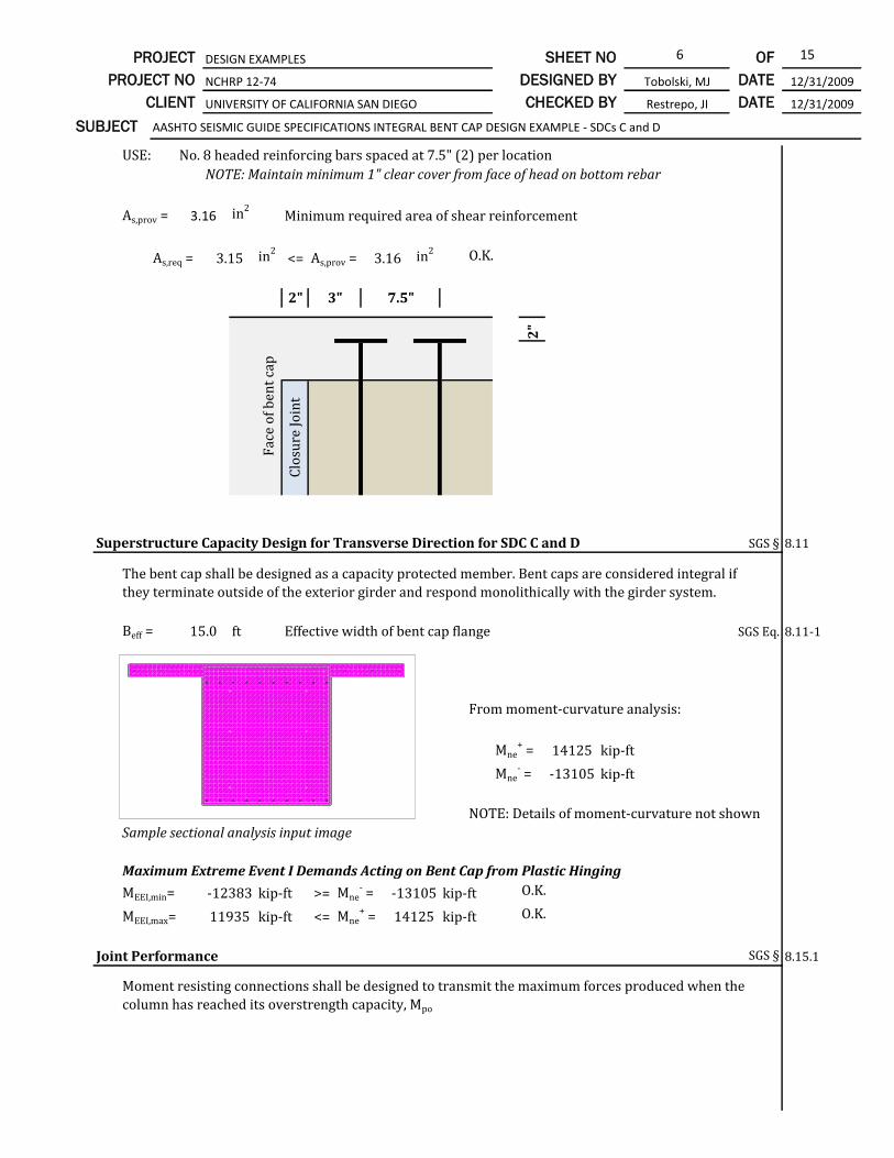
6 15PROJECT DESIGN EXAMPLES SHEET NO OF
CLIENT UNIVERSITY OF CALIFORNIA SAN DIEGO CHECKED BY Restrepo, JI DATE 12/31/2009
PROJECT NO NCHRP 12-74 DESIGNED BY Tobolski, MJ DATE 12/31/2009
SUBJECT AASHTO SEISMIC GUIDE SPECIFICATIONS INTEGRAL BENT CAP DESIGN EXAMPLE - SDCs C and D
USE: No. 8 headed reinforcing bars spaced at 7.5" (2) per location
NOTE: Maintain minimum 1" clear cover from face of head on bottom rebar
As,prov = in2Minimum required area of shear reinforcement
As,req = in2<= As,prov = in2 O.K.
2"
2"
Superstructure Capacity Design for Transverse Direction for SDC C and D SGS § 8.11
Beff = ft Effective width of bent cap flange SGS Eq. 8.11-1
From moment-curvature analysis:
Mne+ = kip-ft
Mne- = kip-ft
NOTE: Details of moment-curvature not shown
Sample sectional analysis input image
Maximum Extreme Event I Demands Acting on Bent Cap from Plastic Hinging
MEEI,min= kip-ft >= Mne- = kip-ft O.K.
MEEI,max= kip-ft <= Mne+ = kip-ft O.K.
Joint Performance SGS § 8.15.1
14125
-13105
The bent cap shall be designed as a capacity protected member. Bent caps are considered integral if
they terminate outside of the exterior girder and respond monolithically with the girder system.
15.0
-12383 -13105
11935
Clo
sure
Jo
int
3" 7.5"
Fac
e o
f b
ent
cap
3.16
3.15 3.16
Moment resisting connections shall be designed to transmit the maximum forces produced when the
column has reached its overstrength capacity, Mpo
14125

7 15PROJECT DESIGN EXAMPLES SHEET NO OF
CLIENT UNIVERSITY OF CALIFORNIA SAN DIEGO CHECKED BY Restrepo, JI DATE 12/31/2009
PROJECT NO NCHRP 12-74 DESIGNED BY Tobolski, MJ DATE 12/31/2009
SUBJECT AASHTO SEISMIC GUIDE SPECIFICATIONS INTEGRAL BENT CAP DESIGN EXAMPLE - SDCs C and D
Joint Proportioning SGS § 8.15.2
Principal Stresses
Principal stresses in the joint are limited by the following equations:
Principal compression, pc : pc ≤ 0.25 f'ce = ksi maximum SGS Eq. 8.15.2.1-1
Principal tension, pt : pt ≤ 0.38 √f'ce = ksi maximum SGS Eq. 8.15.2.1-2
Bcap = in
Dc = in
Ds = in
lac = in Note 1
Pc = kips
Pb = kips Note 2
h = ft Note 3Mpo,cap = kip-ft Note 3
Notes:
1)
2) No prestressing in section.
3)
pt = = ksi Principal tension stress in joint SGS Eq. 8.15.2.1-3
pc = = ksi Principal compression stress in joint SGS Eq. 8.15.2.1-4
Tc = Mpo / h kips Column tensile force at ultimate (from analysis above) SGS § 8.15.2
Ajv = lac Bcap = in2Vertical joint area SGS Eq. 8.15.2.1-6
vjv = Tc / Ajv = ksi Vertical joint shear stress SGS Eq. 8.15.2.1-5
Ajh = (Dc + Ds) Bcap = in2Horizontal joint area SGS Eq. 8.15.2.1-8
fv = Pc / Ajh = ksi Vertical joint shear stress SGS Eq. 8.15.2.1-7
fh = Pb / (Bcap Ds) = ksi Horizontal joint stress SGS Eq. 8.15.2.1-9
pc = ksi ≤ ksi maximum OK
pt = ksi ≤ ksi maximum OK
0.0
2781
0.502 1.30 Joint proportions are acceptable based
on principal stress requirements.0.433 0.867
0.433
0.502
0.466
5964.0
0.0682
12096
825
0
3.7910540
Length of column longitudinal rebar extended
into cap. See calculations below.
Determined from sectional analysis. Tension
in column longitudinal rebar may also be
derived from sectional analysis.
1.30
0.867
84.0
60.0
84.0
71.0
fh + fv + fh - fv
2+ v2
jv
2
fh + fv
2- fh - fv
2+ v2
jv
2
fh fh
fv
fv
vjv
vjv
vjh
vjh
Pc
Vocol
Mbleft
Tc Cc
Vbleft
Tbleft
Cbleft
Mbright
Vbright
Tbright
Cbright
Bcap
Ds
Dc
Mpocol

8 15PROJECT DESIGN EXAMPLES SHEET NO OF
CLIENT UNIVERSITY OF CALIFORNIA SAN DIEGO CHECKED BY Restrepo, JI DATE 12/31/2009
PROJECT NO NCHRP 12-74 DESIGNED BY Tobolski, MJ DATE 12/31/2009
SUBJECT AASHTO SEISMIC GUIDE SPECIFICATIONS INTEGRAL BENT CAP DESIGN EXAMPLE - SDCs C and D
Minimum Development Length of Column Longitudinal Reinforcement SGS § 8.15.2.2
lac ≥ 2 dbl fye dbl = in (#11 rebar) Eq. 8.15.2.2.2-1
fye = ksi
f'cg = ksi = min (7.5 ksi, 7.0 ksi) per Article 8.15.2.2.2
lac = in (minimum)
lac = Dgirder - 3" = in
in ≥ in (minimum) OK Extend to top face of cap less 3 in cover.
Minimum Joint Shear Reinforcing for Precast Bent Cap Connections SGS § 8.15.3
Check if principal tension, pt, is ≥ 0.11√f'c (condition for likely joint cracking)
Calculated tension = ksi
Limit, 0.11√ f'ce = ksi
pt = ksi ≥ ksi limit Additional joint reinforcement is required.
Calculate required volumetric ratio of transverse joint reinforcement:
Maximum of: ρs ≥ 0.11 √f'c / fyh Eq. 8.15.3.1-1
ρs ≥ 0.40 Ast / l2ac Eq. 8.15.3.1-2
Ast = in2
lac = in
Maximum of: 0.11 √f'ce / fyh = governs Eq. 8.15.3.1-1
0.40 Ast / l2ac = Eq. 8.15.3.1-2
Use ρs ≥
ρs =
Asp = in2(#6 hoop)
D'gd = in (confined diameter of column between centroids of #6 hoop)
0.0025
0.0042
Assume transverse reinforcement in the joint is the same size as the column plastic hinging region
transverse reinforcement.
0.44
57.92
0.433 0.251
31.20
71.0
0.0042
71.0
71.0 27.4
Where principal tension in the joint is greater than or equal to 0.11√ f'c and joint proportioning is
acceptable per Article 8.15.2, additional transverse joint reinforcement for cap pocket connections
per Article 8.15.5.2.3 is to be added, and Eqs. 8.15.3.1-1 and 8.15.3.1-2 are to be satisfied.
0.433
0.251
f'cg
1.41
68
7.0
27.4
Extend column reinforcement as far as practically possible into precast bent cap portion; assume
3" clear from opposite face of precast bent cap. Additional cover provided after casting of deck.
4Asp
D'gd s
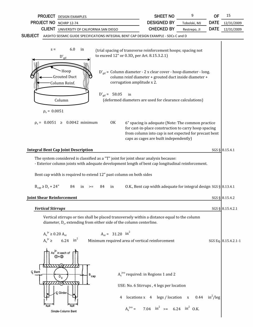
9 15PROJECT DESIGN EXAMPLES SHEET NO OF
CLIENT UNIVERSITY OF CALIFORNIA SAN DIEGO CHECKED BY Restrepo, JI DATE 12/31/2009
PROJECT NO NCHRP 12-74 DESIGNED BY Tobolski, MJ DATE 12/31/2009
SUBJECT AASHTO SEISMIC GUIDE SPECIFICATIONS INTEGRAL BENT CAP DESIGN EXAMPLE - SDCs C and D
s = in
D'gd =
D'gd = in
(deformed diameters are used for clearance calculations)
ρs =
ρs = ≥ minimum OK
Integral Bent Cap Joint Description SGS § 8.15.4.1
Bent cap width is required to extend 12" past column on both sides
Bcap ≥ Dc + 24" in >= in O.K., Bent cap width adequate for integral design SGS § 8.13.4.1
Joint Shear Reinforcement SGS § 8.15.4.2
Vertical Stirrups SGS § 8.15.4.2.1
Asjv ≥ 0.20 Ast Ast = in2
Asjv ≥ in2
Minimum required area of vertical reinforcement SGS Eq. 8.15.4.2.1-1
Asjvo required: in Regions 1 and 2
USE: No. 6 Stirrups , 4 legs per location
4 4 x
Asjvo = in2
>= in2O.K.
84 84
Vertical stirrups or ties shall be placed transversely within a distance equal to the column
diameter, Dc, extending from either side of the column centerline.
31.20
6.24
locations x legs / location 0.44 in2/leg
7.04 6.24
The system considered is classified as a "T" joint for joint shear analysis because:
- Exterior column joints with adequate development length of bent cap longitudinal reinforcement.
Column diameter - 2 x clear cover - hoop diameter - long.
column reinf diameter + grouted duct inside diameter +
corrugation amplitude x 2.
58.05
0.0051
0.0051 0.0042
6.0 (trial spacing of transverse reinforcement hoops; spacing not
to exceed 12" or 0.3Ds per Art. 8.15.3.2.1)
6" spacing is adequate (Note: The common practice
for cast-in-place construction to carry hoop spacing
from column into cap is not expected for precast bent
caps as cages are built independently)
D'gd
Grouted Duct
Column Reinf.
Column
Hoop

10 15PROJECT DESIGN EXAMPLES SHEET NO OF
CLIENT UNIVERSITY OF CALIFORNIA SAN DIEGO CHECKED BY Restrepo, JI DATE 12/31/2009
PROJECT NO NCHRP 12-74 DESIGNED BY Tobolski, MJ DATE 12/31/2009
SUBJECT AASHTO SEISMIC GUIDE SPECIFICATIONS INTEGRAL BENT CAP DESIGN EXAMPLE - SDCs C and D
SGS Figure 8.15.4.2.1-1
Asjvo ≥ 0.175 Ast Ast = in2
Asjvo ≥ in2
Minimum required area of vertical reinforcement outside joint SGS Eq. 8.15.5.1.1-1
USE: No. 6 Stirrups , 4 legs per location Asjvo = in2
>= in2O.K.
Spacing outside of joint region: in
Asjvo ≥ 0.135 Ast Ast = in2
Asjvo ≥ in2
Minimum required area of vertical reinforcement inside joint SGS Eq. 8.15.5.1.2-1
3 4 x
Asjvo = in2
>= in2O.K.
Horizontal Stirrups SGS § 8.15.4.2.2
Asjh ≥ 0.10 Ast Ast = in2
Asjh ≥ in2
Minimum required area of horizontal reinforcement SGS Eq. 8.15.4.2.1-1
DP/C= in Depth of precast bent cap
Nspace,min = DP/C / 18in = Minimum number of spaces between cross ties
Minimum number of cross ties (excluding bottom of vertical stirrups) 5
Space at 12" and hook on side
face reinforcement
USE: No. 4 cross ties
Place at each vertical stirrup
locations
x ties / location
x in2/tie
Asjh = in2
>= in2O.K.
SGS Figure 8.15.4.2.1-3
4.21
locations x legs / location 0.44
5.28 4.21
in2/leg
For multi-column bents, vertical stirrups shall additionally be provided in accordance with
Article 8.15.5. Overlapping vertical stirrups from shall count towards meeting the requirements
31.20
5.46
7.04 5.46
31.20
The minimum bar size for
horizontal stirrups shall be No. 4
reinforcement per SGS
§8.15.4.2.2
31.20
3.12
80.00
4.4
0.2
5.00
3.12
5
5
10.0
Horizontal stirrups or ties shall be placed transversely around the vertical stirrups or ties in two
or more intermediate layers spaced verticallys at not more than 18 inches.

11 15PROJECT DESIGN EXAMPLES SHEET NO OF
CLIENT UNIVERSITY OF CALIFORNIA SAN DIEGO CHECKED BY Restrepo, JI DATE 12/31/2009
PROJECT NO NCHRP 12-74 DESIGNED BY Tobolski, MJ DATE 12/31/2009
SUBJECT AASHTO SEISMIC GUIDE SPECIFICATIONS INTEGRAL BENT CAP DESIGN EXAMPLE - SDCs C and D
From inspection, this provision is satisfied.
Horizontal Side Reinforcement SGS § 8.15.4.2.3
0.10 Acaptop = in2
Acaptop = in2
SGS Eq. 8.15.4.2.3-1
0.10 Acapbot = in2
Acapbot = in2
Assf ≥ in2
Minimum horizontal side face reinforcement required
DP/C= in Depth of precast bent cap
Nspace,min = DP/C / 18in = Minimum number of spaces between reinforcement
Minimum number of locations of reinforcement per side of bent cap 7
USE: No. 5 side face reinforcement throughout cap with maximum spacing of 12 inches
Assf= 7 = in2
>= in2O.K.
J-Bars SGS § 8.15.4.2.4
Skew is less than 20° therefore no J-bars are required.
Additional Longitudinal Cap Beam Reinforcement SGS § 8.15.4.2.5
Asjl ≥ 0.245 Ast Ast = in2
Asjh ≥ in2
Additional longitudinal cap beam reinforcement SGS Eq. 8.15.5.1.3-1
Torsional Shear-Friction Requirement SGS § 8.10.5
31.20
7.64
For multi-column bents, horizontal stirrups shall additionally satisfy the requirements of Article
8.15.5
For multi-column bents, additional longitudinal cap beam reinforcement shall satisfy the
requirements of Article 8.15.5
For integral cap of bents skewed greater than 20° vertical J-bars hooked around the longitudinal
top deck steel are required.
For precast girder systems, there is no bottom soffit slab present to aide in the transfer of moment
and shear demands from the superstructure to the column. Therefore, these demands are transferred
through the bent cap by a torsional mechanism. The small distance between the face of the column
and beams will not facilitate the development of traditional torsional spiral cracks, thus conventional
torsional design provisions are not valid. Torsional capacity is calculated using a plastic torsional
shear friction mechanism.
1.56
The total longitudinal side face reinforcement in the bent cap shall be at least equal to the
greater of the following two requirements with a maximum spacing of 12 inches.
Assf ≥
15.60
12.48
1.56
1.25
1.56
80.00
6.7
0.31locations x in2/location 2.17

12 15PROJECT DESIGN EXAMPLES SHEET NO OF
CLIENT UNIVERSITY OF CALIFORNIA SAN DIEGO CHECKED BY Restrepo, JI DATE 12/31/2009
PROJECT NO NCHRP 12-74 DESIGNED BY Tobolski, MJ DATE 12/31/2009
SUBJECT AASHTO SEISMIC GUIDE SPECIFICATIONS INTEGRAL BENT CAP DESIGN EXAMPLE - SDCs C and D
Bcap= in Bent cap width
Dcap= in Total depth of bent cap including deck
Acap= in2Total area of bent cap
As,mild = in2Total area of mild reinforcement in bent cap (+ side face)
Aps = in2Total area of post-tensioning in bent cap
As,totalcap = As,mild + Aps = in2
Total area of steel in bent cap (mild and post-tensioning)
fpe= ksi Effective post-tensioning force including losses
P = Apsfpe + As,totalcapEs(0.0005) = kip Total compression force including steel force
developed from dilation of section
µ = Shear friction coefficient (bent cap in continuous)
τ = [µ P] / Acap = kip/ft2Shear friction stress
T = 0.5 Mpo,cap = kip-ft Torsional demand on bent cap
VV = 0.5 Pc = kip Vertical shear demand on bent cap
VL = 0.5 Vo = kip Longitudinal shear demand on bent cap
φ = Strength reduction factor for shear LRFD § 5.5.4.2
T = φ τ [ A1x1 + A2x2 + A3x3 + A4x4 ] Torsional shear friction resistance
VV = φ τ [ A1 - A4 ] Vertical shear friction resistance
VL = φ τ [ A2-A3 ] Longitudinal shear friction resistance
Bedding Layer Reinforcement SGS
8.15.5.2.1
7560
5270
413
357
0.9
4
Total
T
VV
VL
2.72
2.90
Required
5270
413
357
423
415
84.0
90.0
34.0
36.4
Distance from
Centroid, ft
1.95
2.10
1
2
39.19
30.08
9.11
162
2045
1.4
54.5
First moment
centroid, ft^3
Area
ft^2
17.44
17.35
3
Region
55.8 28.2
30
.55
9.5
23.9
25.8
120.2
Check
OK
OK
OK
8.81
8.90
52.50
Capacity
5897
Provide bedding layer transverse reinforcement to match the size and type used in the column
plastic hinging region (#6 bar). Hoop will be placed at mid-height in the bedding layer; bedding
layer to be 3" thick. Cover on top column hoop to be 1.5" as shown in figures below, and
resulting center-to-center spacing of transverse reinforcement is 3" throughout, in accordance
with Article 8.8.14.
VV
VLTF1
F2
F3
F4

13 15PROJECT DESIGN EXAMPLES SHEET NO OF
CLIENT UNIVERSITY OF CALIFORNIA SAN DIEGO CHECKED BY Restrepo, JI DATE 12/31/2009
PROJECT NO NCHRP 12-74 DESIGNED BY Tobolski, MJ DATE 12/31/2009
SUBJECT AASHTO SEISMIC GUIDE SPECIFICATIONS INTEGRAL BENT CAP DESIGN EXAMPLE - SDCs C and D
Figures Showing Final Design
Elevation View at Column Connection
Typical Section at Column Connection

14 15PROJECT DESIGN EXAMPLES SHEET NO OF
CLIENT UNIVERSITY OF CALIFORNIA SAN DIEGO CHECKED BY Restrepo, JI DATE 12/31/2009
PROJECT NO NCHRP 12-74 DESIGNED BY Tobolski, MJ DATE 12/31/2009
SUBJECT AASHTO SEISMIC GUIDE SPECIFICATIONS INTEGRAL BENT CAP DESIGN EXAMPLE - SDCs C and D
Clear cover may be less
than 2" per Art. 8.8.14
3" overall spacing
maintained
Typical Section at Girder Connection
Closeup of Bedding Layer
Bent Cap
Bedding
Layer
Column
1.5"
1.5"
per Art. 8.15.5.2.1
per Art. 8.8.14

15 15PROJECT DESIGN EXAMPLES SHEET NO OF
CLIENT UNIVERSITY OF CALIFORNIA SAN DIEGO CHECKED BY Restrepo, JI DATE 12/31/2009
PROJECT NO NCHRP 12-74 DESIGNED BY Tobolski, MJ DATE 12/31/2009
SUBJECT AASHTO SEISMIC GUIDE SPECIFICATIONS INTEGRAL BENT CAP DESIGN EXAMPLE - SDCs C and D
Plan View at Connections