Embed Size (px)
Citation preview
DE2 Electronic Keyboard with the Autoplayer Feature ReadMeFirst
Lab Summary At the end of this lab your ever expanding circuit design will automatically play an entire song stored in read only memory. You will augment the keyboard design from last week with circuitry that outputs keyboard codes in the correct order and duration to generate the tune.
Lab Background The automatic playback circuit requires a much slower clock than the ones that are currently available from previous designs. In Part 1 of the Lab, you will build the required clock, the DemoClock.
The DemoClock is then incorporated into the sequencing circuit that will be called DemoPlayer (Part 2). This is a complex design that steps through the music data and controls the timing of automated key codes sent to the Keyboard circuit from the last lab.
There are intermediate steps in Part 2 which ask you to verify that a sub-circuit is working before adding additional circuitry. This is the reason that you are asked to make different connections, and add or delete switches and LEDs to test the circuit. These steps are intended to save you hours of troubleshooting your design.
In Part 3, the DemoPlayer is added to the Keyboard design from last week to enable the Autoplay feature on each of 2 channels. Autoplay will be a switch selectable option so that, if Autoplay is not selected, the DE2 Board will still function using the PS2 keyboard as in the last lab.
This Readme will walk you through how to construct and test the 2-channel Autoplayer from the Keyboard project you have already constructed. Hierarchy, if used correctly, will reduce this large project to a straightforward exercise.
Lab Preparation
Documents Demo_Player_Notes.pdf
Electronic Keyboard Circuit.pdf
Supplies
Speaker x 1 DE2 Board x 1
USB Blaster Cable x 1 PS/2 Keyboard x 1
Part 1: The DemoClock
Procedure 1:
1) Project->Copy Project the Keyboard project from the previous lab.
2) Verify that your Keyboard project still functions before continuing.
3) Copy autoplayClock.v into your new project directory and add the file to the
project. Procedure 2:
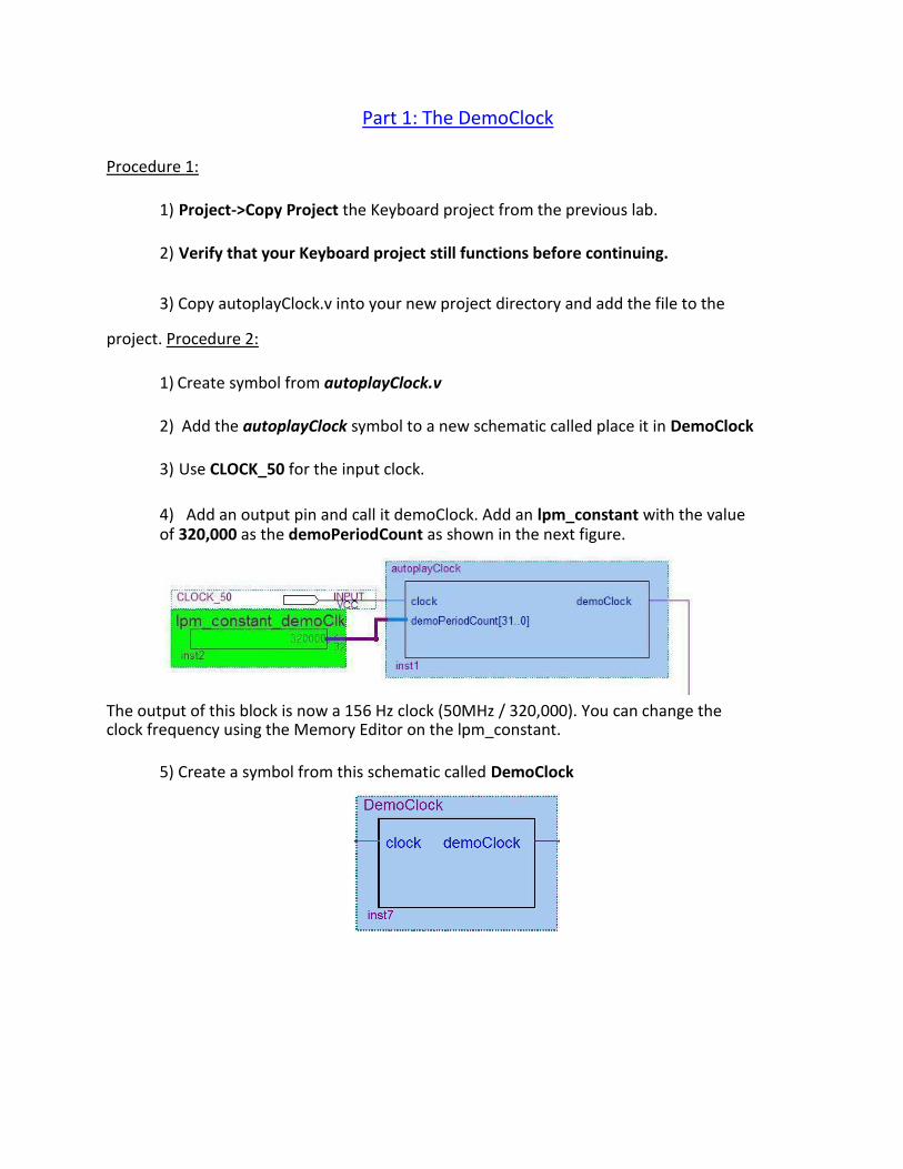
1) Create symbol from autoplayClock.v
2) Add the autoplayClock symbol to a new schematic called place it in DemoClock
3) Use CLOCK_50 for the input clock.
4) Add an output pin and call it demoClock. Add an lpm_constant with the value of 320,000 as the demoPeriodCount as shown in the next figure.
The output of this block is now a 156 Hz clock (50MHz / 320,000). You can change the clock frequency using the Memory Editor on the lpm_constant.
5) Create a symbol from this schematic called DemoClock
Part 2: Demo Player Feature
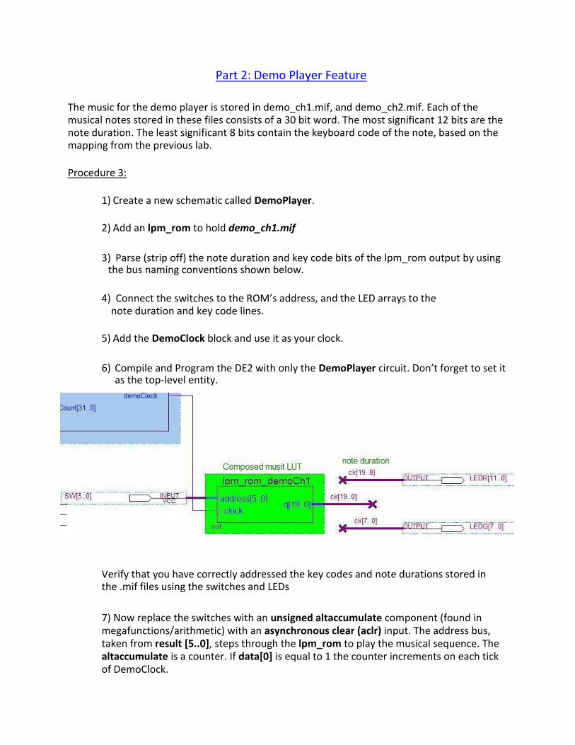
The music for the demo player is stored in demo_ch1.mif, and demo_ch2.mif. Each of the musical notes stored in these files consists of a 30 bit word. The most significant 12 bits are the note duration. The least significant 8 bits contain the keyboard code of the note, based on the mapping from the previous lab.
Procedure 3:
1) Create a new schematic called DemoPlayer.
2) Add an lpm_rom to hold demo_ch1.mif
3) Parse (strip off) the note duration and key code bits of the lpm_rom output by using
the bus naming conventions shown below.
4) Connect the switches to the ROM’s address, and the LED arrays to the
note duration and key code lines.
5) Add the DemoClock block and use it as your clock.
6) Compile and Program the DE2 with only the DemoPlayer circuit. Don’t forget to set it
as the top-level entity.
Verify that you have correctly addressed the key codes and note durations stored in the .mif files using the switches and LEDs
7) Now replace the switches with an unsigned altaccumulate component (found in megafunctions/arithmetic) with an asynchronous clear (aclr) input. The address bus, taken from result [5..0], steps through the lpm_rom to play the musical sequence. The altaccumulate is a counter. If data[0] is equal to 1 the counter increments on each tick of DemoClock.
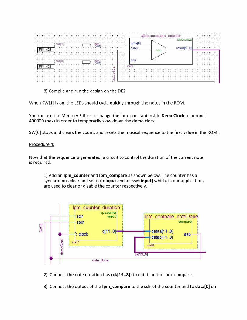
8) Compile and run the design on the DE2.
When SW[1] is on, the LEDs should cycle quickly through the notes in the ROM.
You can use the Memory Editor to change the lpm_constant inside DemoClock to around 400000 (hex) in order to temporarily slow down the demo clock
SW[0] stops and clears the count, and resets the musical sequence to the first value in the ROM..
Procedure 4:
Now that the sequence is generated, a circuit to control the duration of the current note is required.
1) Add an lpm_counter and lpm_compare as shown below. The counter has a synchronous clear and set (sclr input and an sset input) which, in our application, are used to clear or disable the counter respectively.
2) Connect the note duration bus (ck[19..8]) to datab on the lpm_compare.
3) Connect the output of the lpm_compare to the sclr of the counter and to data[0] on
the altaccumulate. You can delete SW[1].
The lpm_counter is the timer for the current note duration. When the counter value equals the note duration, in the lpm_compare, the aeb output toggles states. This causes the altaccumulate to increment the address bus to access the next note, and resets the lpm_counter to zero.
4) Connect the SW[0] to the sset line on the lpm_counter to reset the note duration counter whenever the demo player is reset.
5) Compile and test your design.
Procedure 5:
To make the music sound less mechanical, it is necessary to insert a 4 cycle pause between each note.
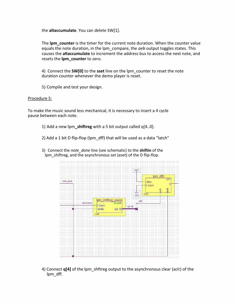
1) Add a new lpm_shiftreg with a 5 bit output called q[4..0].
2) Add a 1 bit D flip-flop (lpm_dff) that will be used as a data "latch"
3) Connect the note_done line (see schematic) to the shiftin of the
lpm_shiftreg, and the asynchronous set (aset) of the D flip-flop.
4) Connect q[4] of the lpm_shftreg output to the asynchronous clear (aclr) of the lpm_dff.
The output of the D Flip_flop is now a 4 clock cycle pulse that is set by note_done and cleared by the 4th bit of the shift register.
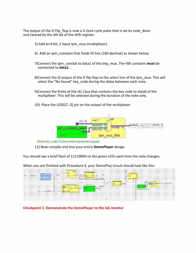
5) Add an 8 bit, 2 input lpm_mux (multiplexor).
6) Add an lpm_constant that holds F0 hex (240 decimal) as shown below.
7) Connect the lpm_constat to data1 of the lmp_mux. The F0h constant must be
connected to data1.
8) Connect the Q output of the D flip-flop to the select line of the lpm_mux. This will
select the "No Sound" key_code during the delay between each note.
9) Connect the 8 bits of the ck[ ] bus that contains the key code to data0 of the
multiplexer. This will be selected during the duration of the note only.
10) Place the LEDG[7..0] pin on the output of the multiplexer
11) Now compile and test your entire DemoPlayer design.
You should see a brief flash of 11110000 on the green LEDs each time the note changes.
When you are finished with Procedure 4, your DemoPlay circuit should look like this:
Checkpoint 1: Demonstrate the DemoPlayer to the lab monitor
Part 3: Adding the Demo Player to the Keyboard Synthesizer
.
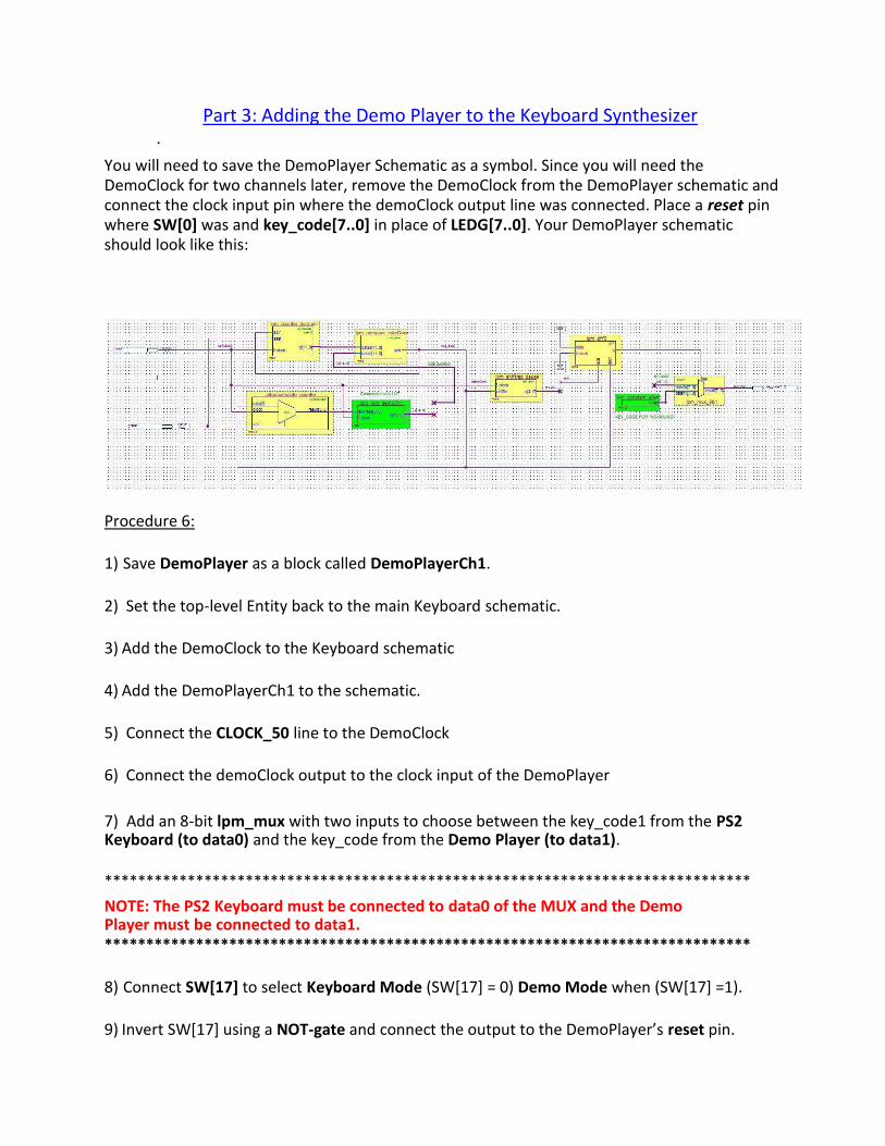
You will need to save the DemoPlayer Schematic as a symbol. Since you will need the DemoClock for two channels later, remove the DemoClock from the DemoPlayer schematic and connect the clock input pin where the demoClock output line was connected. Place a reset pin where SW[0] was and key_code[7..0] in place of LEDG[7..0]. Your DemoPlayer schematic should look like this:
Procedure 6:
1) Save DemoPlayer as a block called DemoPlayerCh1. 2) Set the top-level Entity back to the main Keyboard schematic. 3) Add the DemoClock to the Keyboard schematic 4) Add the DemoPlayerCh1 to the schematic. 5) Connect the CLOCK_50 line to the DemoClock 6) Connect the demoClock output to the clock input of the DemoPlayer
7) Add an 8-bit lpm_mux with two inputs to choose between the key_code1 from the PS2 Keyboard (to data0) and the key_code from the Demo Player (to data1).
****************************************************************************** NOTE: The PS2 Keyboard must be connected to data0 of the MUX and the Demo Player must be connected to data1. ******************************************************************************
8) Connect SW[17] to select Keyboard Mode (SW[17] = 0) Demo Mode when (SW[17] =1). 9) Invert SW[17] using a NOT-gate and connect the output to the DemoPlayer’s reset pin.
You have completed a two channel Keyboard Synthesizer with a Demo Player on the first channel.
Compile and test your design before continuing.
Add the second channel of the DemoPlayer.
Procedure 7:
1) Save DemoPlayerCh1 as DemoPlayerCh2.
2) Delete the lpm_rom in DemoPlayerCh2 and replace it with a NEW lpm_rom that contains demo_ch2.mif.
3) Create a symbol block for DemoPlayerCh2 and wire it up on channel 2 the same way as you set up channel 1. 4) Connect SW[17] to switch between Keyboard and Demo Modes for both channels.
5) Compile and test your circuit.
Checkpoint 2: Demonstrate your electronic keyboard with the autoplay feature to the lab monitor. ******************************************************************************
Troubleshooting:
● The Memory Editor should be enabled for all Constants and ROM’s. Use this to check for failed memory initialization and to reinitialize the memory.
● Verify that none of your synchronous components are missing a clock line. CHeck that
you did not use the wrong clock:
○ CLOCK_50 goes to the AD/DA converter, the PS/2 Keyboard control block and
the clock divider. ○ AUD_DACLRCK is used for the synthesizers.
○ demoClock (from autoplayClock) is used only for the autoplay.
● Pay Attention to the MUX inputs, data0 & data1! DON'T reverse the input buses. Some blocks will not function correctly if the mux data inputs are mixed up.
******************************************************************************

Checkpoint 3: Clean up and show your workbench to the lab monitor.
Discussion Questions
Topic 1: Why do you need the of the DemoClock component for the design? How does it work?
Topic 2: How would you change the speed of the Autoplayer music without recompiling?
Topic 3: What is the D flip-flop used for in the circuit?
Topic 4: What does the bit shifting do on the output of the Channel blocks?
Topic 5: Why won't bit shifting work if the Channel block output bus has the same name as the bus coming from lpm_ROM wave?