Embed Size (px)
Citation preview

1
DEALING WITH THE COLD: A LOOK AT ¼ TURN BALL VALVES AND COLD SERVICE DECISIONS
Nathaniel Paxton Mike Wood
Valves & Measurement Group Cameron International Corporation
ABSTRACT
What is considered cold for valve applications? Even this is a subjective matter in terms of valve preparedness. One thing is for sure, cold applications these days require more than just a valve handling cold temperatures, which is difficult enough. Cryogenic valves are used in a host of applications ranging from liquefaction of dried natural gas, to air separation, to gas [trailer] transport, food processing, and pharmaceuticals, to name a few. Cryogenic valves are vital to the proper and efficient operation of these processes. Common issues have been identified that, if understood and addressed in a timely fashion, can help the following:
1. Avoid start-up problems;
2. Improve the ability of the valve to properly operate, increasing the throughput of the unit
3. Extend the life of the valves, saving money in costly, unscheduled repairs
4. Reduce unexpected shutdowns — keeping the revenue stream flowing.
INTRODUCTION
The study of “cold” has a rich history. Since the first quarter of the 19th century, many scientists and natural philosophers have taken on its study which has opened up its extraordinary secrets by dispelling many myths. Commercializing on the mastery of these discoveries, life on this planet has never been the same. One has to consider the advancements that have taken place. In the early 1800’s, a temperature of -110 °C (-166 °F) was not proven to even exist. The vocabulary, never mind the means to attain it, did not exist. Through many years of experimentation and the rough road of trying to commercialize on scientific breakthroughs in the marketplace, we enjoy the advancements to human life and the comfort it brings. It has been generally accepted, at least commercially, that the cryogenic temperature range starts at minus -150 °C (-238 °F). Certain gases are considered “cryogenic” because it takes more than just an increase in pressure to compress a volume of gas – as stipulated by Robert Boyle. Little did he know at the time (1665) that the relationship between volume and pressure would much later become the cutting edge for cold research. [Absolute Zero and the Conquest of Cold, Tom Shachtman,* 1999, Houghton Mifflin Company].
Today, anything warmer than cryogenic temperatures is considered “refrigeration,” at least for the sake of our discussion at hand. Refrigeration, at one time, was the temperature range required for the preservation of food from 3 °C to 5 °C (37 °F to 41 °F). Later on the range went as low as -43 °C (-45 °F) upon the discovery that fast freezing of food became commercially viable. Later still, the temperature range decreased to -110 °C (-166 °F) on the onset of non-cryogen liquefaction. This then set the stage for the descent toward the liquefying of cryogens and the descent towards absolute zero.
*
2
Now we get down to the matter of understanding cold as it pertains to the “mundane” matter of valve selection. There are a number of things we need to understand about cold temperatures when considering how we go about selecting a valve that will work over the long term. What do we have to take into consideration in terms of the physical properties of cryogens themselves and materials that will handle them?
The valve industry is conservative. A general rule is that continuous temperatures less than -73 °C (-100 °F) is considered cold service and warrants valve preparation for cryogenic service. The reasons will be discussed in this paper. There are always exceptions to this rule, as many readers can probably attest, but for the sake of this discussion, that will be the general rule.
PROBLEMS ASSOCIATED WITH TRANSPORT OF CRYOGENS
How does one handle the transport of media that does not want to be a liquid at atmospheric pressure from a thermodynamic point of view? It is not easy! Leakage of cryogens is not only dangerous, but also very expensive especially when one considers the cost to make a gas a cryogen in the first place.
As it pertains to the valve, it has been said many times that thermal swings can be the Achilles heel for any valve and severe temperature variations of a cryogenic nature take this to a new level. The components of any valve (body, bonnet, stem, stem seals, ball, and seats) will contract and expand at different rates because of different material composition or amount of time exposed to the cryogen. Defining what is “Intermittent” or “steady state” service further complicates matters. People tend to take intermittent service less seriously; but thermal growth differences of valve components take its toll which can potentially lead to premature failure.
When one considers the seat leakage potential for a ¼ turn ball valve, for example, one can readily see that there is bound to be a concern at the ball/seat interface for certain materials. When cryogenic temperatures are involved, the thermal expansion difference between a PTFE (Polytetrafluoroethylene) based seat and a 316 stainless (316 SS) ball is greatly enhanced - to the point where it becomes a design consideration. PTFE expands approximately five times the rate of 316 SS (both are common materials for cold temperatures). What goes together and tests well on the bench is no guarantee of seal tightness in the deep cold where seat geometry and surface finish play a big role.
The linear and radial growth of the stem in relation to the body can often be underestimated. Properly designed stems (and stem seals) need to bridge this thermal rate of expansion difference as they are tasked to dynamically seal on the stem outside diameter (OD) and packing chamber inside diameter (ID) at all times. The consequences can be sometimes severe if not problematic. This is described in more detail under Basic Valve Design Objectives.
Heat gains from the environment are forever a constant battle when dealing with cryogens – hence the reason for valve and piping insulation. One has to remember what we are dealing with during gas processing - in terms of the physical properties of gases, such as Liquefied Natural Gas (“LNG” which is mostly methane - CH4 ), nitrogen, oxygen, argon, helium, and the like. These ‘liquids’ do not want to be liquids at atmospheric pressure and, if allowed, can violently transform to gases in a heartbeat (approximately a 700:1 expansion factor going from liquid to a gas). In the normal processing of cryogens, there is always the buildup of pressure because of this heat gain from the environment and the subsequent vapor formation. There needs to be provisions in the valves/piping system to allow for this pressure build up.

3
VALVE CONFIGURATIONS USED IN CRYO SERVICE
While there isn’t a rule as to when to use any particular style of valve for cryogenic service, which is typically clean media, it does appear that there is a customer preference for ¼ turn motion where tight shut off is concerned. This ¼ turn motion is accomplished by use of ball valves or high performance/ triple offset butterfly valves (TOBV). For large valve sizes, gate valves are often utilized. There is a point where triple offset valves [TOV] are used because the mass of a ball valve often makes it cost prohibitive above 10” size. There are people who do use ball valves in the larger size range – it just depends how much one wants to pay “up front” versus “later on” in terms of valve performance over time.
As for the type of piping connections, flange and welded configurations are used mostly for cryogenic service and it depends on customer preference which type is used. Either of these connection types can handle a wide pressure range; the majority of applications being ASME Class 150 – 600. Certainly, there are applications for Class 1500 – 2500.
Though not written in stone, ball valves are typically used in the ½” – 16” range for cryo service, with the majority of the ball valves up through 8”. High performance / triple offset butterfly valves are commonly used in the 10” – 32” range and, as previously indicated, the 24” – 56” seems to be the domain of gate valves.
The marketplace offers different body designs for ball valves. For flanged valves, an end entry (some refer to this as side entry) uni-body type design is available; where there are no breaks in the valve body that could be considered potential leak paths to the environment. To access the internals, there is a threaded end plug that inserts into one of the flanges. A second option is a split body arrangement where the end plate (sometimes called a tail piece) is bolted to the body. To access the internals, the two components are unbolted.

4
There are “3 piece” body arrangements for ball valves, which means a body center section and two end plates (sometimes called pipe ends) that are bolted to the body. The end plate contains the type of connection used in the application – some form of welded or threaded connection. This design is popular because the center section can swing out while the valve is in line – making the valve in line repairable after it is isolated. As with flanged valves for cryo service, a welded extension is fabricated to the body for cryogenic service.
Gate valves utilize rising stem motion and a bolted bonnet to the body.
There are typically no seams or connections in triple offset butterfly valve bodies. These bodies are long or short ISO gate, lug, or wafer configurations. The butterfly face-to-face dimensions are all one-piece castings which are not fabricated from smaller sections. However, a cryogenic design will likely require a welded pipe extension at the top of the body to extend the stem packing, similar to ball or gate valves.
Three (3) piece body design
Split body design
End entry uni-body body design

5
If a three (3) piece valve is indeed to be welded inline, without first undertaking the recommended disassembly and replacement of soft parts, heat damage to the body seals and seats from the welding process or the post weld heat treatment (PWHT) must be considered. It is strongly recommended that the valves are disassembled after welding and seats and seals replaced – but this is often ignored. Depending on the skill of the welder, it is possible to weld a valve inline without doing any heat damage to soft seal components. Body seals are the “soft” components that create a seal between the body and the two endplates that comprise a 3-pc. valve. The seats may be reusable after welding, but they too should be checked for damage. Many times, body seal and seat replacement is overlooked and this causes problems later during start up.
Most people are risk averse and will not take that chance of welding inline; especially with projects where large numbers of small valve installations are involved. As a result, designers often specify pup extensions to remove the concerns of heat damage to the body seal components during welding process. Keeping track of body seal replacement parts [that come with the valve] specifically for the post weld replacement can also be a nightmare, as they are frequently discarded inadvertently. Pup extensions take the welding process away from the end connections of the valve – so that the possibility of heat damage is greatly reduced and body seal component replacement is not necessary.
There is often a desire to eliminate potential leak paths when installing valves for large liquid natural gas (LNG) projects; particularly for the smaller valves, 2”and below (and there are usually a lot of them). As a consequence, some piping engineers have moved from a three (3) piece body design (two possible leak paths) towards a top entry design. There is one potential leak path with a top entry valve – that being the bonnet to body flange connection which is required to access the internals of the valve. There are many who believe that maintenance is easier with a top entry valve because it would be in-line repairable. However, testing the valve in-line for sealing integrity after the repair may be difficult to accomplish. For larger valves especially, scaffolding is often required to access the valve and take it apart. After all that time and expense to do this, some feel more compelled to take the valve out of line so that it can be tested for sealing integrity. In any case, there are always two sides to any claim; so each designer (ultimately the buyer) must decide what the best philosophy for their plant is.
Top Entry Body Design

6
BASIC VALVE DESIGN OBJECTIVES
The same American industry standards used to manufacture process valves are also utilized for valves used in cold service; nothing changes in this regard. Compliance to ASME B31.3 Boiler and Pressure Code and ANSI B16.34 lead the list. API 600, 602, 603 would apply to gate valves; API 602 for gate, globe and check valves, API 608 for ball valves, and API 609 for butterfly valves. As it pertains to large projects in particular, European and International Standards also prevail. Often, there are many material specifications involving the choice of castings or forgings and the subsequent quality, verification, and non-destructive testing of each.
For cryogenic valves, an area of concern is to maintain ductility at low temperatures and to obviously use materials that work in this low temperature range. Brass can be used and is often specified. The material mostly specified for cold temperatures is 316 stainless steel, in its forged or cast form, for body and internal components. Valve specifications can get very detailed on the nondestructive testing requirements, radiography, material impact testing, and positive material identification (PMI). The manufacturer will need to determine the most economical choice for the manufacture of its products while meeting these specifications.
For ball valves especially, there is general consensus that nothing that seals better than fluoropolymer materials (generally classified as thermoplastics). There are numerous melt processable and powder forms of fluoropolymers such as PTFE which was previously mentioned, PCTFE (Polychlorotrifluoroethylene - formally trade marked as KEL-F by 3M Corporation), FEP (Fluorinated ethylene propylene, PFA (Perfluoroalkoxy polymer resin, and ECTFE (Ethylene chlorotrifluoroethylene). Some have higher strength characteristics than others, but all exhibit non-stick and friction reducing properties. These materials are universally impervious to most media and lend themselves particularly well to cryogenic media.
Fluoropolymers are used for both the seat and stem seal components. If fire safety is a requirement and the melting of Fluorpolymers is a concern, graphite stem seals can replace PTFE or any fluoropolymer that would be typically used for cryogenic applications. A fire lip will need to be machined into the body which facilitates the metal to metal contact between the ball and body, should the seats melt during a fire. While this concept is not new, it does mean that there needs to be the effort of qualifying these cryogenic valves to fire test standards; something that is often not done.
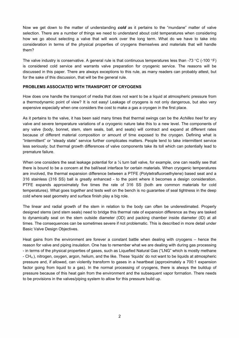
Isolation of the stem seals from cryogenic temperatures will require an extended bonnet. Note that the cryogen is constantly boiling off and forming vapor. The concept is to capture a column of this vapor between the diametrical clearance of the stem and the extended bonnet. This vapor exerts pressure on the cryogenic liquid itself and prevents its contact with the stem seals. If the cryogen reaches the stem seals, problems will result. Fluoropolymers shrink approximately five times faster than the surrounding metal in the valve and the stem seals will not function properly. Over time, as the cryogen leaks and absorbs heat as it vaporizes to the atmosphere, ice will form. This can take the form of an “ice ball” on top of the bonnet extension. The handle (or actuator/coupling area), will be impeded and the valve will not operate.
7
Retention Screw 700:1 expansion ratio
cha
The preferred method to attach the extended bonnet to the body is a full penetration weld. This method ensures weld integrity and one that is also strong – being better able to handle unanticipated moment loads from people using valves as ladders for example. This can most easily be achieved via a butt weld type connection. In addition, seamless tubing for the bonnet extension should be used. There is no recognized standard in the valve industry that addresses bonnet height. Valve companies have calculated and incorporated designs that work for their products. There are some end user specifications (Shell MESC SPE 77 for example), which do specify minimum bonnet extension heights (called thermal lagging) for all types of valves.
As previously noted, the 700:1 liquid to gas expansion ratio makes it acutely necessary to have a stem design that is blow out resistant. If this design feature is not in place, the stem could physically jettison itself from the valve if the actuator/gear operator/ handle were removed. Not putting the retention ring screw back in place during normal maintenance has caused major incidences, when the valve was later disassembled, which resulted in significant loss of precious media, evacuation, and personal harm. All it takes is a momentary lapse in judgment. It is worth emphasizing that during valve repair that precautions are necessary; the retention ring screw must be properly put back in place before the valve is in service again.
In addition to the blow out proof stem, there must be a way for Cavity Pressure Relief (CPR) within the valve to remedy a liquid to vapor transition. Cavity pressure build-up can destroy the sealing components of a valve. It can also distort the ball or cause the valve to leak externally pass the body seal(s) if it is a split body design or three (3) piece design. The worst case scenario is a catastrophic failure to the whole piping system itself. For a ball valve, the most dependable way to relieve pressure build-up is through a hole in the high pressure side of the ball. However, this modification makes the valve uni-directional. When a valve is uni-directional by design, it must be indicated which side is the high pressure end. The high pressure end will be the same side as the pressure relief device. This information is covered in the installation instructions that come with the valve, but for whatever reason, they are often not read. As a result, valves can be installed backwards with the relief side pointing towards the low pressure side, the valve will experience seat leakage in the closed position. If cavity pressure relief was not a design concern, there would be no need for a vented ball. Consequently, the valve would be bi-directional and the preferred pressure side marking is not required.
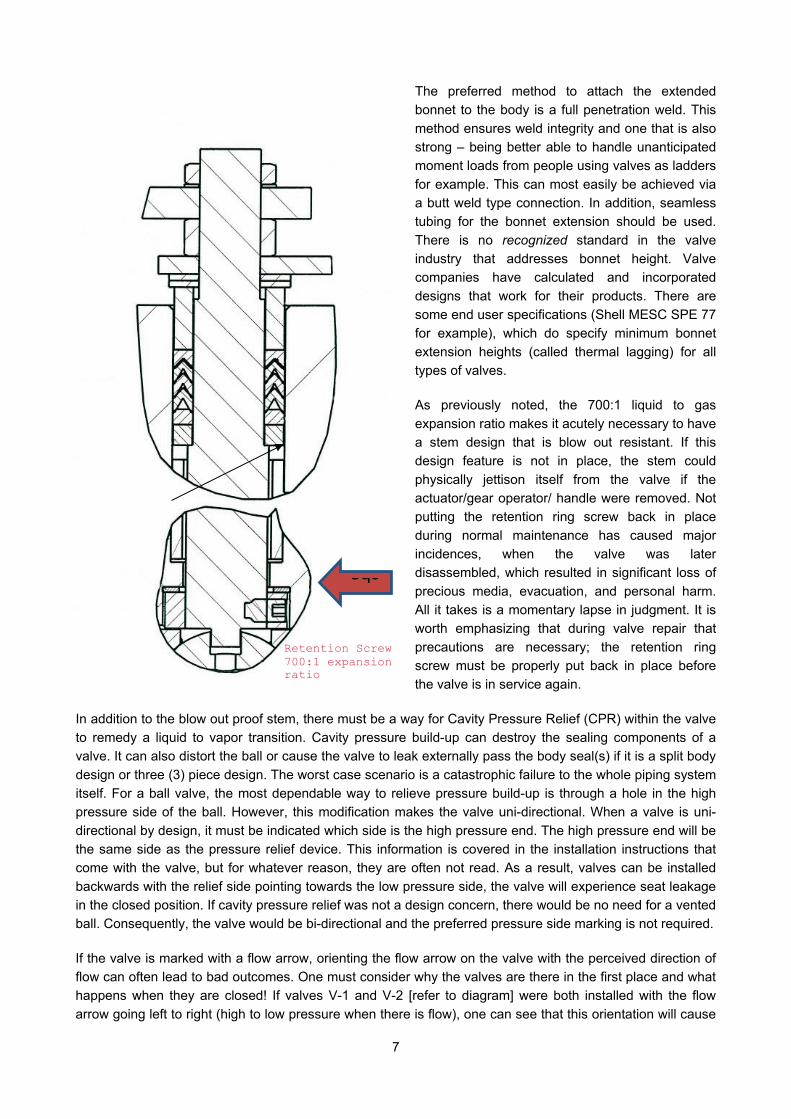
If the valve is marked with a flow arrow, orienting the flow arrow on the valve with the perceived direction of flow can often lead to bad outcomes. One must consider why the valves are there in the first place and what happens when they are closed! If valves V-1 and V-2 [refer to diagram] were both installed with the flow arrow going left to right (high to low pressure when there is flow), one can see that this orientation will cause
8
problems when the valves are actually shut and pump 1 removed. When pump 1 is indeed removed, the high pressure side of the valve is now the side facing away from the pump which is where the relief device (hole in the ball) should be. This will result in leakage through the CPR device which has been erroneously installed on the side closest to the pump.
The above scenario makes “self-relieving” options attractive where a soft seat flexes and relieves on its own during pressure upsets. However, there is unpredictability with this design method as to when the seat actually relieves and in which direction. For valves with higher pressure requirements (Class 1500 and above), stiffer seat materials are required to effectively seal, and getting the seat to flex is even more difficult to do when using the “self-relieving” option. Despite this unpredictability, there is still an attraction to this type of design because the valve remains bi-directional.
For larger sized ¼ turn valves where both bi-directionality and cavity pressure relief is required, a third method of CPR is available. A cavity pressure relief device can be externally mounted to the outside of the valve that enables CPR relief to the upstream side while maintaining bi-directionality. It must be noted that while, in this example, the valve is bi-directional, the CPR is not. Valves with CPR systems must be installed in the line as a unidirectional would be, or the CPR will relieve downstream.
A rising stem gate valve will also need CPR capability – this is accomplished by way of the high pressure end of wedge and split gate configurations. Slab gate valves have self-relieving seats and do not require CPR.
It is recommended that a cryogenic valve with PTFE stem seals should not be installed more than 45 degrees from the vertical. This is a precautionary measure to keep the cryogen away from the stem seals. Installers of valves often take exception to this as there are space constraints and pipe interference issues that frequently need to be contended with. Beyond the 45 degree position, the probability of the cryogen making contact with the stem seals goes up, which increases the odds of stem seal failure. When contact is made, PTFE stem seals shrink and they lose full surface contact with the surfaces they are trying to seal against (stem OD and packing chamber ID). If the stem seals are made from graphite, concerns of orientation are not usually a factor as the graphite does not have a rate of thermal contraction like PTFE when exposed to cold temperatures. Graphite maintains its shape when exposed to large temperature fluctuations and certainly seals well enough if the recommended compressive load is applied as specified in the installation instructions.

9
The surface finish for the sealing components of a cryo valve is critical. The slightest imperfection, a slight scratch, the smallest of indentations, a hair, can all lead to unacceptable “through” leakage during cryogenic testing and service. Any buildup on the ball, such as lubricant or shop dirt, can cause leakage or make the valve difficult to operate. This is why clean room capability, stringent cleaning procedures, and component inspection are followed during the assembly of cryogenic valves. The fact that a PTFE based seat material acts very much like metal at cryogenic temperatures only exacerbates these issues – it is not the forgiving and resilient substance we know at ambient conditions.
VALVE DESIGN CONSIDERATIONS
When specifying valves, one probably wonders at some point during the process if there is overkill. Just how robust does one make your valve design requirements? Just how sensitive is the environment in which you are placing these valves? What is at risk? Most folks are likely to use the “standard” offering from valve manufacturers, such as PTFE stem seals, if fire testing is not a concern; graphite seals when it is. Things get more complicated when there are low fugitive emissions (FE) requirements, and even more complicated when fire safety is required at the same time. Under these circumstances, some designers go further by requesting that graphite not be used as the primary seal for a valve that needs to meet both low FE requirements and be fire safe…not easy to do. This configuration would include PTFE based primary seals, and graphite seals as the secondary seals, which would need to be independently loaded to work effectively during and after a fire.
It is not a given that an extended bonnet is required for every cryogenic application. Certainly, almost anybody knows of a cold application where the valve in use does not have a cryo bonnet extension and the valve appears to work fine. With that said, not using extended bonnets where they should be used is not good practice. To make the final determination, one has to understand what is going on with the process itself and what is expected of the valve. People often do not specify extended bonnets if the service is perceived to be intermittent, or if there are physical constraints prohibiting their use. Most valve companies have a non-extended bonnet option where a cryo valve is offered with body and seat materials suitable for cold temperatures, except there is no cryogenic bonnet. If valves in a cold “area” are considered utilitarian in scope - like a drain or vent application – people may opt not to use a bonnet.
What’s a better cryo bonnet construction – bolted or welded? If one is comfortable with welding techniques, a welded joint can certainly eliminate a potential leak path. A bolted bonnet design can be a leak path consideration, especially if actuators are involved. If the valve/actuator units are installed off the vertical position, the overhanging mass can put strain on the bonnet bolts. Thermal cycling can also create havoc, as it would for any bolted design. Added safety can be gained by specifying some form of non-destructive testing for welded connections – either dye penetrate inspections or radiography - which is an added cost. All things considered, it just comes down to field experience and what has worked over time.
Valves intended for cryogenic service should be assembled in a clean room, be lubricant free, or utilize lubricants compatible with cold service. The valves should not have machine oils, grease, dirt, or any foreign material in the valve for the clean service for which it is intended. Any extraneous matter can inhibit the performance of sealing at cryogenic temperatures. Anything that can get in between the ball and seat can cause sealing problems. The buyer should insist to see documented procedures for cleaning, and should verify they are actually being followed during the assembly process.
Passing the rigors of witnessed cryogenic testing is not easy. One knows from their own experiences that “cryo” valves that work at ambient conditions often do not work at cold temperatures. Similarly, valves that work at cold temperatures may not work well when subjected to warm temperatures again. Torque values may not be consistent in the cold, which is why most cryogenic testing requires testing over a range up to the maximum rated pressure of the valve. Cryo testing also requires the valves to be warmed to ambient conditions to make sure they still seal.

10
Most importantly, the buyer needs to know that a given valve manufacturer uses the right materials and has the standards of workmanship so that the everyday “process” produces valves that consistently work in cold conditions. The valves that are shipped must have the proper material and quality certification documentations, along with the pertinent production testing results that shows the rigors of the manufacturing process.
THROTTLING IN CRYOGENIC SERVICE
In cold service, care must be taken when throttling with PTFE based soft seat materials. Throttling occurs when the ball position is somewhere between the completely closed and completely open position. During throttling, the seats are unsupported by the ball surface and can shrink faster than the metal ball because of their physical properties. If seat contraction does occur and if the ball rotates back across the seat, the seat may fracture as it now interferes with the ball’s rotation. As previously mentioned, PTFE becomes very hard at cold temperatures, so it is not the resilient material we know it to be at room temperature. If the valve is allowed time to fully cool, then this theoretically should not be a problem. The question is how much time is enough to constitute a steady state condition?
To allay these concerns, a buyer may specify round port metal seats which will shrink at the same rate as the ball when subjected to cold conditions. Round port metal seats can be used for crude control, or if a more precise flow characteristic is desired, a characterized seat suited for the flow conditions can be designed, as with any control application. A characterized control seat is always metallic. It can be used with the round port metal seat for a given control valve.
If metal seats are used and if coatings are desired, there are options available as to the application of those coatings onto the metal ball and seat surfaces. The coating can be diffused into the substrate surface so that the coating actually becomes part of the component itself. On the other hand, layered coatings sit on top of the metal surface (ball or seat) and may delaminate during the severe thermal cycling which would be the nature of some cryogenic applications.
CLOSING
When selecting valves for cold service, the reader of this article should not assume that a valve designed for “middle of the road” process conditions, coupled with an extended bonnet and seats compatible for cold service, constitutes a cryogenic valve. These applications should not be taken lightly; especially when these cold temperature requirements are coupled with fire safety, low fugitive emissions, and tight shut off. You want to be involved with a valve manufacturer that has experience – with testing and in real applications, and who has high quality standards.
There are not many companies that are willing to rigorously prepare valve components for clean room assembly and take the precautions to keep components contaminant free – at least to the degree required by the industry. It is important to verify that a potential supplier does what they say they do on an everyday basis – not just when you are looking. While it may be more expensive up front, you want to be supported after installation. Your decision to go with an experienced supplier for cold service will pay off down the road.
Let the buyer beware!
ABOUT THE AUTHORS
Nathaniel Paxton is currently the TBV™ Product Manager for Cameron International Corporation, located in Millbury, MA. He earned his BSME from SUNY @ Buffalo and his MBA from UMASS. Nate has a varied background of work experience with job challenges ranging from Research and Development, Design, Manufacturing, Business Development, and Product Management with a diverse range of companies including Dresser Clark, A.W. Chesterton, Varian, Worcester Controls and Cameron. Nate has spent a

11
majority of his 30 years of experience as a product champion for his lines in a managerial role involving all facets of the business focusing on product development and sales.
Mike Wood is the Business Development Manager for Gas Processing & LNG for Cameron International Corporation. He began his career in June 1974 and has held various management positions with the company. He spent much of his career working closely with global customers in the areas of quality, design, and performance on valve-related challenges. With his combined 38+ years of valve, actuation and process experience, Mike is highly regarded in the valve industry as a Rising Stem Ball Valve expert, particularly in the investigation and repair of valves in the oil/gas processing industry and provides solutions where customers use critical service valves in the gas processing industry.