Embed Size (px)
Citation preview
www.modernpowersystems.com October 2008 Modern Power Systems 33
HEAT RECOVERY STEAMGENERATORS
Dealingwith tube cracking atHerdecke andHamm-UentropCountermeasures have been successfully implemented to address tube cracking in the HP Evaporator 2
sections of the HRSGs at Herdecke and Hamm-Uentrop. These are of the Cottam type, an innovative BensonTM
design with lowmass flux vertical tubes in a horizontal exhaust flow.
Joachim Franke and Jan Brückner, Siemens, Erlangen,Germany
Around three months aftercommissioning in September/October2007 cracks and leaks wereencountered in heat recovery steam
generator HP evaporator tubes at Trianel’s 2 x400MWeHamm-Uentrop combined cycle plantin Germany. Similar damage was also found atMark E’s new 1 x 400MWeHerdecke combinedcycle plant (Figure 1), which employs identicaltechnology.The triple pressure HRSGs, manufactured by
Ansaldo under licence to Siemens, are of aninnovative design (see MPS, February 2006),employing Benson once through evaporators intheir HP sections. The exhaust gas flow ishorizontal and the tubes are vertical. Theyemploy the low mass flux concept, as developedby Siemens (licensor of the Benson technology)and first used at Cottam in the UK.After Cottam, Hamm-Uentrop and Herdecke
are indeed only the second and third combinedcycle plants in the world with this HRSGtechnology to enter service, although there are anumber of other combined cycle plants currentlyunder construction and planned whichincorporate the Benson low mass flux verticaltube design.In Hamm-Uentrop and Herdecke the HRSGs
are installed downstream of Siemens SGT5-4000F (aka V94.3A) gas turbines (as atCottam).
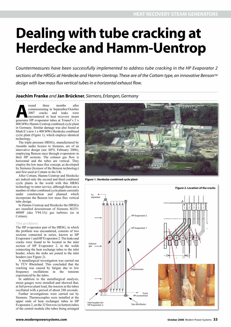
The problemThe HP evaporator part of the HRSG, in whichthe problem was encountered, consists of twosections connected in series, known as HPEvaporator 1 andHPEvaporator 2. The leaks andcracks were found to be located in the inletsection of HP Evaporator 2, in the weldsconnecting the heat exchange tubes to the inletheader, where the stubs are joined to the inletheaders (see Figure 2).A metallurgical investigation was carried out
by TÜV Rheinland. This concluded that thecracking was caused by fatigue due to lowfrequency oscillations in the tensionsexperienced by the tubes.In addition to the metallurgical analysis,
strain gauges were installed and showed that,at full power plant load, the tension in the tubesoscillated with a period of about 240 seconds.Further investigations were carried out by
Siemens. Thermocouples were installed at theupper ends of heat exchanger tubes in HPEvaporator 2, on the 32 first row (ie hottest) tubesof the central module (the tubes being arranged
Figure 1. Herdecke combined cycle plant
Exhaustgas
FromHP economiser
Toseparator
HP Evaporator 2
HP Evaporator 1
Downcomer
Star distributorInlet headers forHP Evaporator 2
Figure 2. Location of the cracks

The end resultTheorifices installedat theHPEvaporator1 inletsrender HP Evaporator 1 stable and successfullyeliminate large temperature oscillations, of thekindshowninFigure3,over thewhole load range,from 40% to 100% gas turbine power.
34 Modern Power Systems October 2008 www.modernpowersystems.com
HEAT RECOVERY STEAMGENERATORS
in three modules across the width of the HRSGconnected in parallel, each module having 32tubeswidth-wise (ie96 tubesacross the fullwidthof the HRSG).The thermocouples showed there were
oscillations in individual tubewall temperatures,with an amplitude of up to ±35 K and a period of~300 seconds (Figure 3).Also, as Figure 4 shows, there was a
temperature spread of 90 K between the tubeswith the minimum temperatures and those withthe maximum temperatures.These variations in temperature among the
tubes leads to unacceptably high stresses at theposition where the cracks were found.In turn, the cause of the temperature
oscillations was found to be dynamic instabilityof HP Evaporator 1. These dynamic instabilities(mass flow fluctuations) were found to have thesame frequency as the temperature oscillations.Simulations clearly demonstrated the dynamic
instability of HP Evaporator 1 at full loadoperation, with oscillating steam quality andmass flow (Figure 5).Figure 5 viewed in combination with Figure 6
demonstrates the relation between the instabilityofHPEvaporator 1 and the resulting temperatureoscillations in the tubes of HP Evaporator 2.The spread between tubes is caused by non-
uniform distribution of the water steammixture within the HP Evaporator 2 inletheader. Figure 6 shows the relation betweenmass flow, steam content and wall temperature(average and at the tube outlet) for a singletube. The average steam quality before HPEvaporator 2 is approximately 0.3. But asmentioned there will be tubes in the HPEvaporator 2 seeing lower and higher steamqualities because of the non-uniformdistribution. At full load conditions theminimum tube wall temperature was 345 °Cand the maximum 435 °C. According to Figure6 the wall temperature of 435 °C correspondsto an inlet steam quality of ~0.1 and 345 °Cto 0.6.
The solutionIt is well established that throttling at theevaporator inlet improves dynamic stability andcan be achieved by inserting orifices. Theorifices are installed at the inlets of HPEvaporator 1 (see Figure 7) and designed toachieve an additional pressure drop of 250mbarat full load.In addition, to reduce the spread of
temperatures by improving the water/steamdistribution at the inlet to HP Evaporator 2, T-pieces (Figure 8) have been installed to doublethe number of feed points into the inlet headersof HP Evaporator 2. These T-pieces reduce thetemperature spread by roughly 20% comparedwith the original design.Finally, to better accommodate the stresses
arising from remaining temperature differencesbetween tubes, expansion loops have beeninstalled at the inlet end of the HP Evaporator 2tubes (Figure9).Theexpansion loops in fact havethe effect of increasing the temperature spreadbut are designed to deal with a range of ± 50 K(averaged over tube height), providing a goodmargin when the other countermeasures aretaken into account.The stress analyses and the fatigue calculations
were performed by the boiler manufacturer anddouble checked by Areva.Temperature measuring devices have been
installed at the outlet of all 96 tubes of the hottest
tube row in HP Evaporator 1 and themeasurements are used to ensure thattemperatures are within the allowable limits.The modifications were completed at
Herdecks on 7 June 2008 and at Hamm-Uentropon 8 August 2008.
Figure 3. Cyclic fluctuations in tube wall temperatures (at outlets)
Figure 4. Time averaged tube wall temperatures (at outlets). Differences of +45 to -45 K from theaverage weremeasured. Green triangles show position of feed-in points in inlet header of HPEvaporator 2
Figure 5. Simulation of dynamic instability in HP Evaporator 1
Time (sec)
Row number
Time (sec)
0 120 240 360 380 600 720 840 960 1080 1200 1320 1440 1560 1680 1800 1920 2040 2160 2280 2400
1 2 3 4 5 6 7 8 9 10 11 12 13 14 15 16 17 18 19 20 21 22 23 24 25 26 27 28 29 30 31 32
0 300 600 900 1200 1500 1800 2100 2400 2700 3000 3300 3600 3900 4200 4500
HP Evaporator 2 tube wall temperatures at the outlets, Position of feed-in points intime averaged HP Evaporator 2 inlet header
Mass flow Mass flow Steam quality Steam qualitymodule 3 module 1 + 2 module 3 module 1 and 2
420
400
380
360
340
320
480470460450440430420410400390380370360350340330320310300
60
55
50
45
40
35
30
25
20
15
10
1.00
0.90
0.80
0.70
0.60
0.50
0.40
0.30
0.20
0.10
0.00
Row 1
Row 13
Row 25
Row 2
Row 14
Row 26
Row 3
Row 15
Row 27
Row 4
Row 16
Row 28
Row 5
Row 17
Row 29
Row 6
Row 18
Row 30
Row 7
Row 19
Row 31
Row 8
Row 20
Row 32
Row 9
Row 21
Row 10
Row 22
Row 11
Row 23
Row 10
Row 24
Tubewalltem
perature
(°C)
Tubewalltem
perature
(°C)
Massflo
w(kg/s)
Steam
quality(%
)

well within the ± 50K spread that the expansionloops are designed to accommodate. So theremaining stresses can be tolerated by the newexpansion loops.Overall, the countermeasures have achieved
the desired result, allowing the HRSGs to beoperated as originally intended.
www.modernpowersystems.com October 2008 Modern Power Systems 37
HEAT RECOVERY STEAMGENERATORS
The installation of T-Pieces at HP Evaporator2 inlets has improved the water/steamdistribution, reducing the temperature spreadamong the tubes.Figures 10 and 11 show examples of typical
measurements taken (at 100 % load) followingimplementation of the countermeasures.Figure 10 shows individual tube wall
temperatures over time. The large fluctuationshave been eliminated – compare withFigure 3.Figure 11 shows typical time averaged tube
wall temperatures (at the tube outlets) for 100%gas turbine power. The temperature spreadrecorded at the tube outlets is less than ± 47 Kover all power levels. But the relevant value forthe design of the expansion loops is the tubewall temperatures averaged over tube height,
which have a smaller spread than that of the tubeoutlet temperatures. Figure 6 gives a qualitativeindication of typical differences between tubewall temperatures at the inlet and tube walltemperatures averaged over the tube height.Post modifications, the spread of tube walltemperatures (averaged over tube height) is MPS
Figure 8. T-pieces double the number feed-inpoints to inlet headers of HP Evaporator 2,improving distribution of the water/steammixture to the heat exchange tubes
Figure 9. Expansion loops fitted at the inletendof the tubes ofHP Evaporator 2accommodate stresses arising fromremaining temperature imbalances
Figure 10. Tube wall temperatures (at outlet) over time, following countermeasures.Compare with Figure 3
Figure 11. Time averaged tube wall temperatures (at outlets) after the countermeasures have beenimplemented (gas turbine at 100% power) – same data as Figure 10
Figure 7.Locationof orifice
installed atthe inlet of HPEvaporator 1
Figure 6. Relation between tubewall temperature (at outlet and averagedover height of tube), steamcontent andmass flow for an individual tube
Steam content at tube inlet (%)
0.00 0.10 0.20 0.30 0.40 0.50 0.60 0.70 0.80 0.90 1.00
Time (sec)
0 600 1200 1800 2400 3000 3600 4200 4800 4500 6000 6600 7200
Tube wall temperature Tube wall temperature Tube massaveraged over tube height (°C) at tube outlet(°C) flow (kg/s)
450
440
430
420
410
100
390
380
370
360
350
340
330
320
310
300
0.75
0.70
0.65
0.60
0.55
0.50
0.45
0.40
0.35
0.30
0.25
0.20
0.15
0.10
0.05
0.00
Tubewalltem
perature
(°C)
480
470
460
450
440
430
420
410
100
390
380
370
360
350
340
330
320
310
300
Tubewalltem
perature
(°C)
Row number
HP Evaporator 2 tube wall temperatures at the outlet, Position of feed-in points intime averaged HP Evaporator 2 inlet header
1 2 3 4 5 6 7 8 9 10 11 12 13 14 15 16 17 18 19 20 21 22 23 24 25 26 27 28 29 30 31 32
480470460450440430420410100390380370360350340330320310300
Tubewalltem
perature
(°C)
Tubemassflo
w(kg/s)
HP Evaporator 1
Expansionloops
Heat exchange tubes(HP Evaporator 2)
Inlet headers forHP Evaporator 2