Embed Size (px)
Citation preview
Debanjan Das
Amrita Mukherjee
Chethan Kumar Gaddam
Ganesh Rahul Bhimanapati
PLASMA GASIFICATION FOR VOC DESTRUCTION
• By using a non-thermal plasma in conjunction with catalytic heterogeneous
chemistry and optimization of energy coupling into the plasma, economic
analyses are expected to show that a more energy efficient (and hence cost
effective) method based upon plasma-remediation can be used for VOC
cleanup.
• Economic and technical comparison of traditional incineration based VOC
removal system and our proposed device based on a case study approach.
• Goal: To design a plasma-based system for volatile organic destruction.
Problem Statement
Concept Map
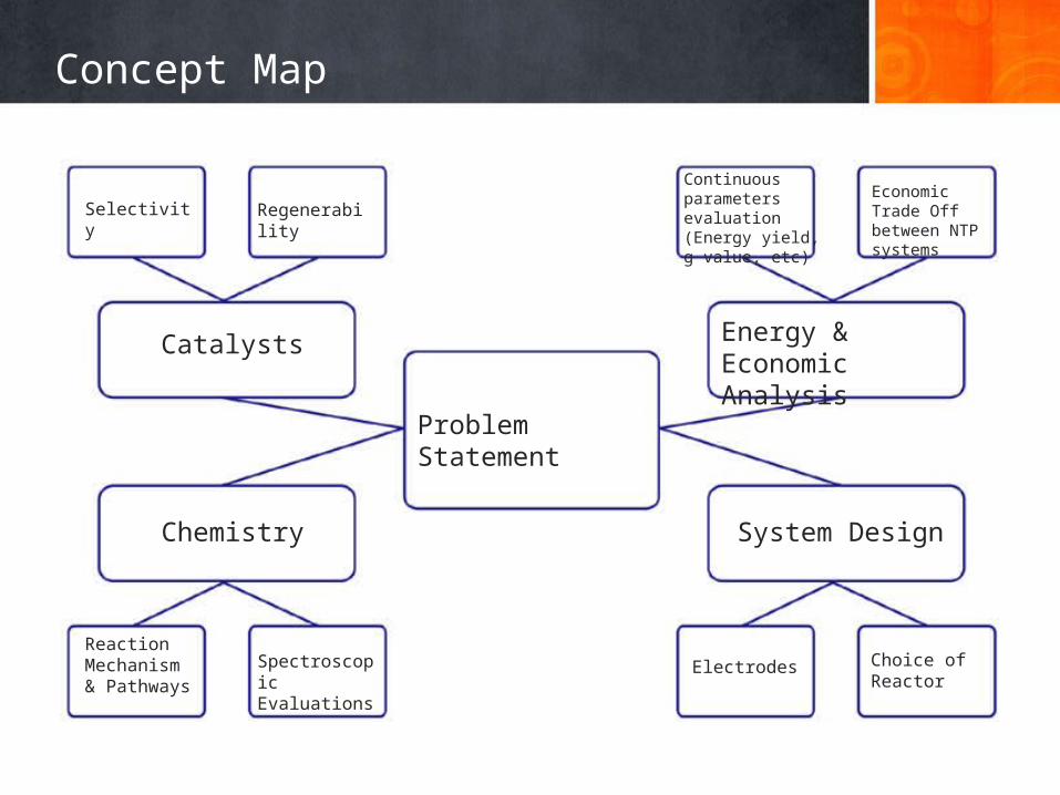
Selectivity
Catalysts
Continuous parameters evaluation (Energy yield, g value, etc)
Energy & Economic Analysis
Problem Statement
Regenerability
Reaction Mechanism & Pathways
Spectroscopic Evaluations
Economic Trade Off between NTP systems
Electrodes Choice of Reactor
Chemistry System Design
VOC
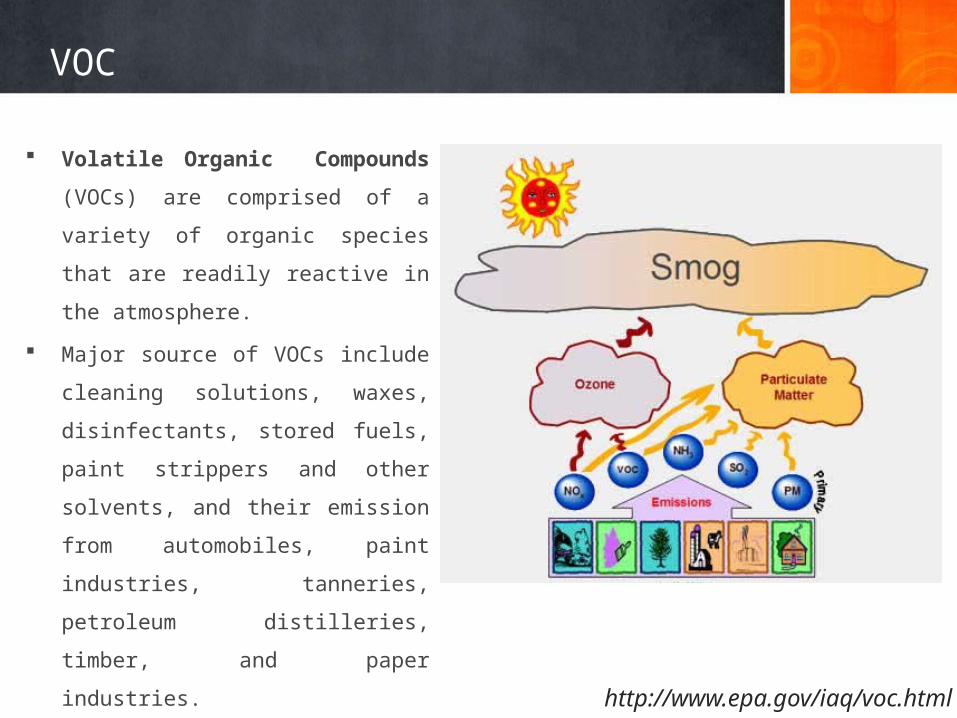
Volatile Organic Compounds (VOCs) are
comprised of a variety of organic species
that are readily reactive in the
atmosphere.
Major source of VOCs include cleaning
solutions, waxes, disinfectants, stored
fuels, paint strippers and other solvents,
and their emission from automobiles,
paint industries, tanneries, petroleum
distilleries, timber, and paper industries.
Examples: hydrocarbons, PAHs,
Chlorinated Aromatic Compounds, etc.
http://www.epa.gov/iaq/voc.html
VOC
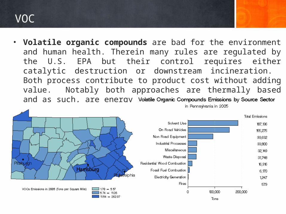
• Volatile organic compounds are bad for the environment and human health. Therein many rules are regulated by the U.S. EPA but their control requires either catalytic destruction or downstream incineration. Both process contribute to product cost without adding value. Notably both approaches are thermally based and as such, are energy intensive.
Plasma
Plasma
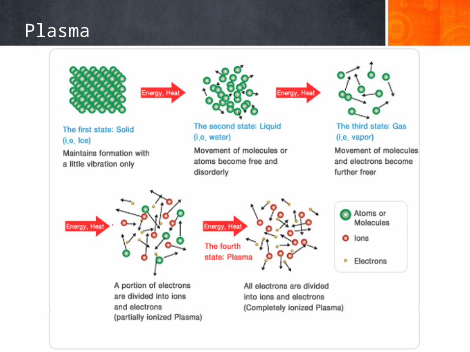
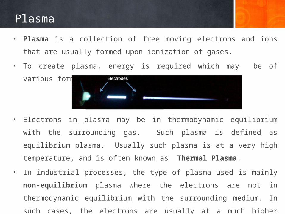
• Plasma is a collection of free moving electrons and ions that are usually formed upon
ionization of gases.
• To create plasma, energy is required which may be of various forms: thermal, electrical
or light energy.
• Electrons in plasma may be in thermodynamic equilibrium with the surrounding gas.
Such plasma is defined as equilibrium plasma. Usually such plasma is at a very high
temperature, and is often known as Thermal Plasma.
• In industrial processes, the type of plasma used is mainly non-equilibrium plasma
where the electrons are not in thermodynamic equilibrium with the surrounding
medium. In such cases, the electrons are usually at a much higher energy level than the
medium. Normally such plasma is at a lower temperature and usually generated from
electrical energy. Such plasma is also known as Non-thermal Plasma
Non-Thermal Plasma
What Is Non-Thermal Plasma?
• Everyone is familiar with static electricity that occurs when reaching for a metal door
handle after walking across a carpet.
• In technical terms, static electricity is the discharge of electricity that occurs when the
potential (that is, voltage) exceeds the insulating effect of the air gap between your
finger and the door handle. Non-thermal plasma uses a reactor that utilizes a similar
effect.
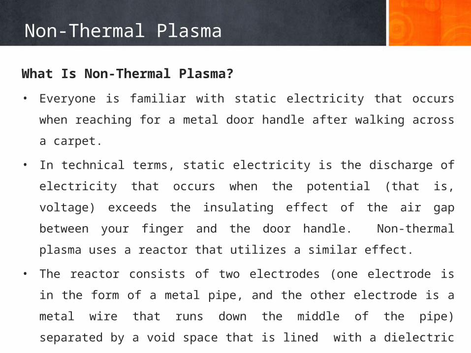
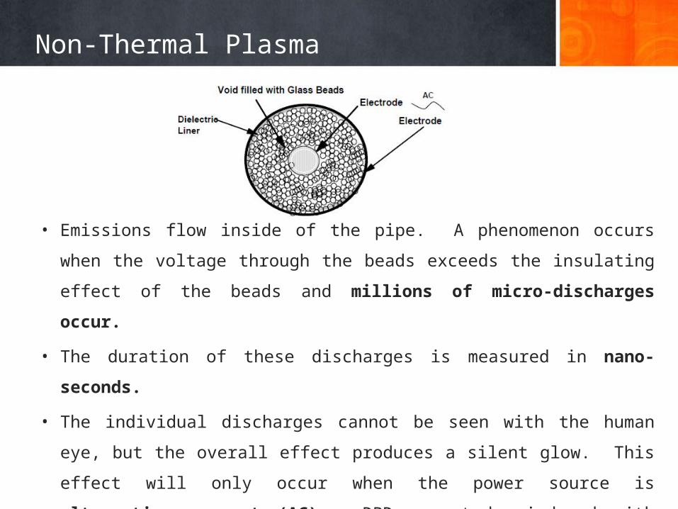
• The reactor consists of two electrodes (one electrode is in the form of a metal pipe,
and the other electrode is a metal wire that runs down the middle of the pipe)
separated by a void space that is lined with a dielectric material and is filled with glass
beads. This type of reactor is called Dielectric-Barrier Discharge (DBD).
Non-Thermal Plasma
• Emissions flow inside of the pipe. A phenomenon occurs when the voltage through
the beads exceeds the insulating effect of the beads and millions of micro-discharges
occur.
• The duration of these discharges is measured in nano-seconds.
• The individual discharges cannot be seen with the human eye, but the overall effect
produces a silent glow. This effect will only occur when the power source is
alternating current (AC). DBD cannot be induced with direct current (DC) power
because the capacitive coupling of the dielectric necessitates an AC field.
Non-Thermal Plasma
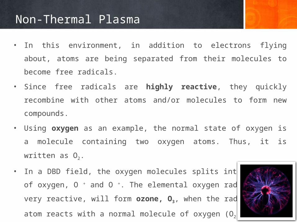
• In this environment, in addition to electrons flying about, atoms are being separated
from their molecules to become free radicals.
• Since free radicals are highly reactive, they quickly recombine with other atoms and/or
molecules to form new compounds.
• Using oxygen as an example, the normal state of oxygen is a molecule containing two
oxygen atoms. Thus, it is written as O2.
• In a DBD field, the oxygen molecules splits into two atoms of oxygen, O + and O +. The
elemental oxygen radical, being very reactive, will form ozone, O3, when the radical
oxygen atom reacts with a normal molecule of oxygen (O2).
Summary of spectral transitions, chemistry equations
1 Chemistry
Electron Impact Ionization
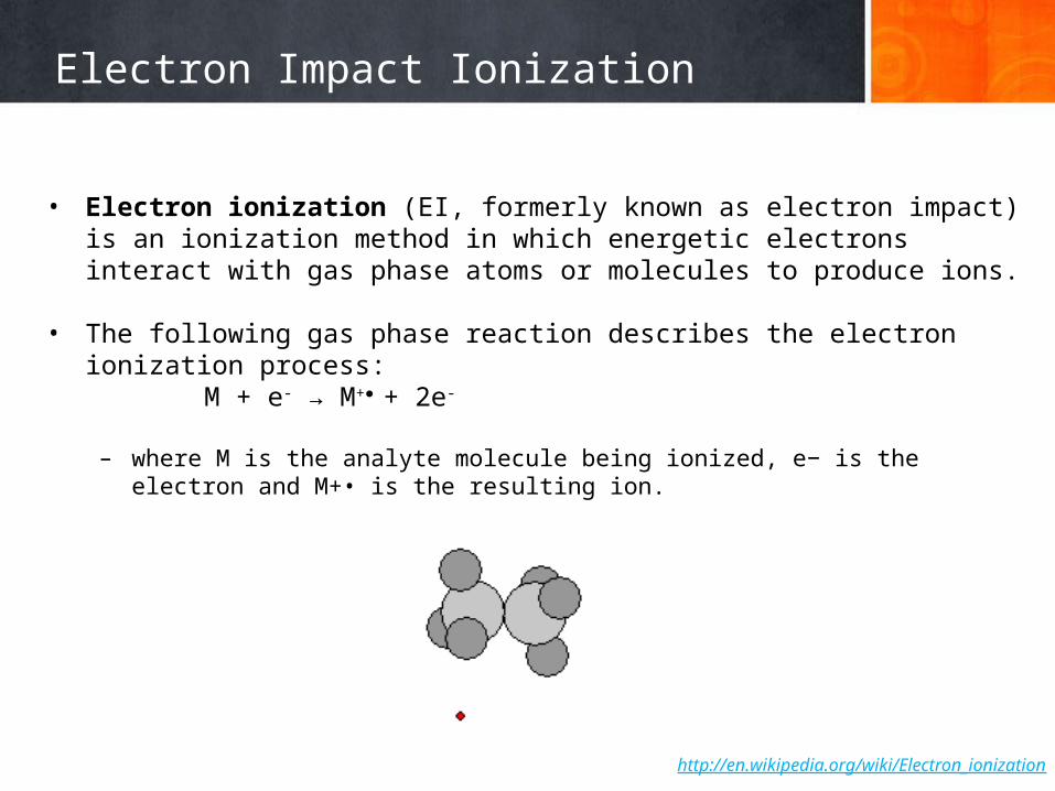
• Electron ionization (EI, formerly known as electron impact) is an ionization method in which energetic electrons interact with gas phase atoms or molecules to produce ions.
• The following gas phase reaction describes the electron ionization process:M + e- → M+● + 2e-
– where M is the analyte molecule being ionized, e− is the electron and M+• is the resulting ion.
http://en.wikipedia.org/wiki/Electron_ionization
Electron Impact Processes
Electron-impact dissociation of molecular oxygen produces the ground state atomic oxygen O(3P) and excited atomic O(1D):
Electron Attachment
Direct dissociation by electron impact
Dissociation by
Electron impact ionization
Electron-impact dissociative ionization
Effects of Oxygen and Water Vapor on Volatile Organic Compounds Decomposition Using Gliding Arc Gas Discharge Plasma Chem Plasma Process (2007) 27:546–558
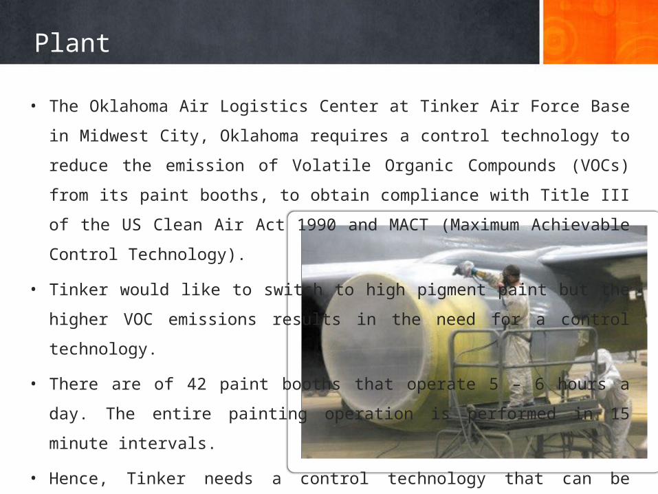
• The Oklahoma Air Logistics Center at Tinker Air Force Base in Midwest City, Oklahoma
requires a control technology to reduce the emission of Volatile Organic Compounds
(VOCs) from its paint booths, to obtain compliance with Title III of the US Clean Air Act
1990 and MACT (Maximum Achievable Control Technology).
• Tinker would like to switch to high pigment paint but the higher VOC emissions results
in the need for a control technology.
• There are of 42 paint booths that operate 5 – 6 hours a day. The entire painting
operation is performed in 15 minute intervals.
• Hence, Tinker needs a control technology that can be turned on and off when required
and instantly operate to full capacity.
Plant
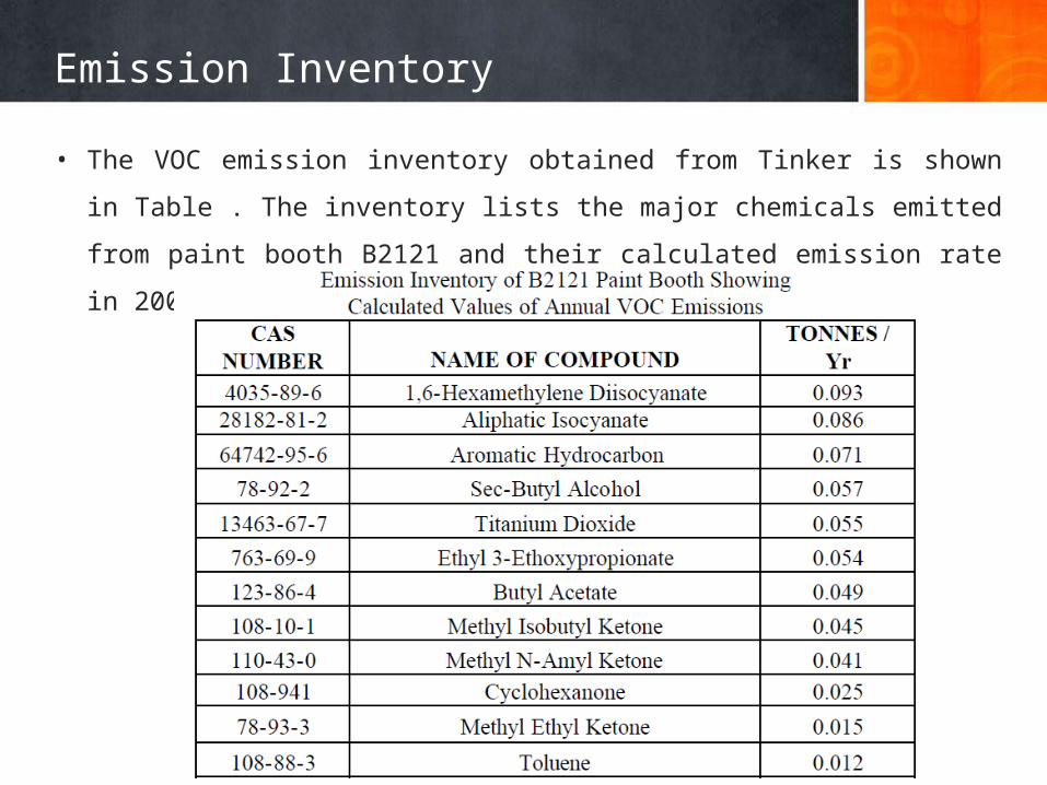
• The VOC emission inventory obtained from Tinker is shown in Table . The inventory
lists the major chemicals emitted from paint booth B2121 and their calculated
emission rate in 2001
Emission Inventory
Destruction of Toluene
Alternative Methods of Toluene Destruction
• Toluene can be removed by adsorption using activated carbon, thermal oxidation and
incineration, bio-filtration and plasma destruction.
• Carbon adsorption is cheap and effective (90%) compared with other methods but the
presence of high concentrations of ketones and alcohols can causes fire in a carbon
bed.
• Finally, the destruction VOCs using an alternate current plasma reactor is effective
(>95% Destruction Efficiency) and potentially less expensive than other competing
technologies.
Destruction of Toluene
• Numerous reactions may take place in a DBD plasma reactor that can lead to the
formation of active species capable of reacting with pollutant molecules.
• These species react with pollutant molecules, which can result in near complete
oxidation of hydrocarbons into CO, CO2, H2O and conversion of species such as Cl, S
and NO into HCl, Cl2, SO2, H2SO4, HNO3.
• If the concentration of the active species is high enough to initiate the destruction
reaction, the pollutant concentration decreases.
Destruction of Toluene
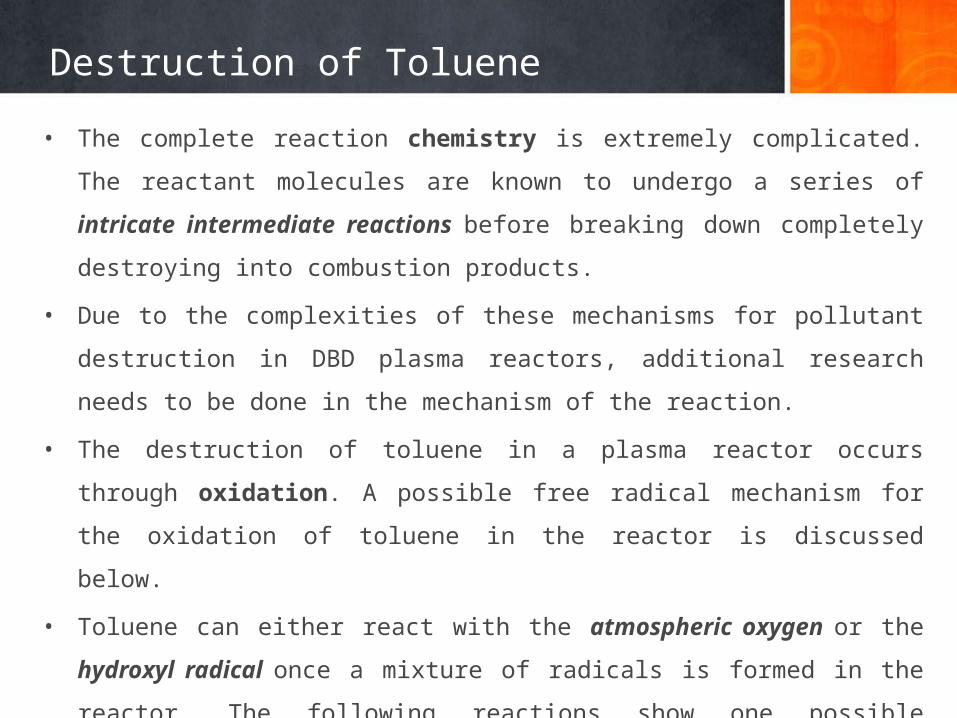
• The complete reaction chemistry is extremely complicated. The reactant molecules are
known to undergo a series of intricate intermediate reactions before breaking down
completely destroying into combustion products.
• Due to the complexities of these mechanisms for pollutant destruction in DBD plasma
reactors, additional research needs to be done in the mechanism of the reaction.
• The destruction of toluene in a plasma reactor occurs through oxidation. A possible
free radical mechanism for the oxidation of toluene in the reactor is discussed below.
• Toluene can either react with the atmospheric oxygen or the hydroxyl radical once a
mixture of radicals is formed in the reactor. The following reactions show one possible
mechanism of toluene destruction in the DBD plasma reactor.
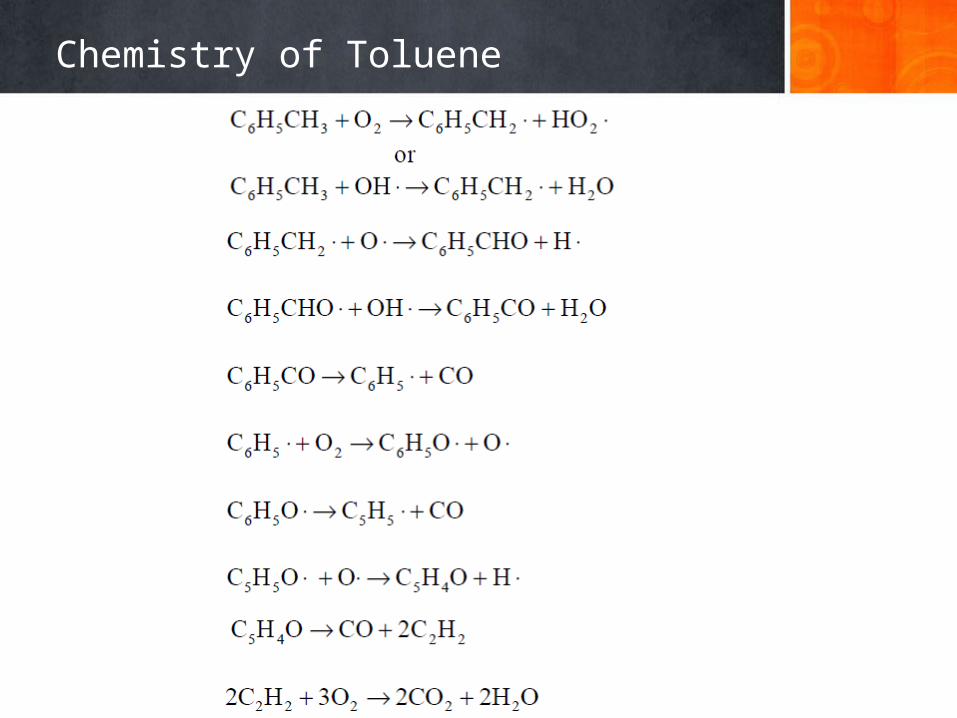
Chemistry of Toluene
Decomposition Toluene
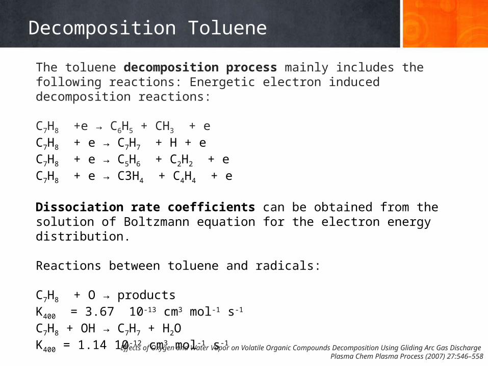
The toluene decomposition process mainly includes the following reactions: Energetic electron induced decomposition reactions:
C7H8 +e → C6H5 + CH3 + eC7H8 + e → C7H7 + H + e C7H8 + e → C5H6 + C2H2 + e C7H8 + e → C3H4 + C4H4 + e
Dissociation rate coefficients can be obtained from the solution of Boltzmann equation for the electron energy distribution.
Reactions between toluene and radicals:
C7H8 + O → productsK400 = 3.67 10-13 cm3 mol-1 s-1 C7H8 + OH → C7H7 + H2OK400 = 1.14 10-12 cm3 mol-1 s-1
Effects of Oxygen and Water Vapor on Volatile Organic Compounds Decomposition Using Gliding Arc Gas Discharge Plasma Chem Plasma Process (2007) 27:546–558
Decomposition of Toluene
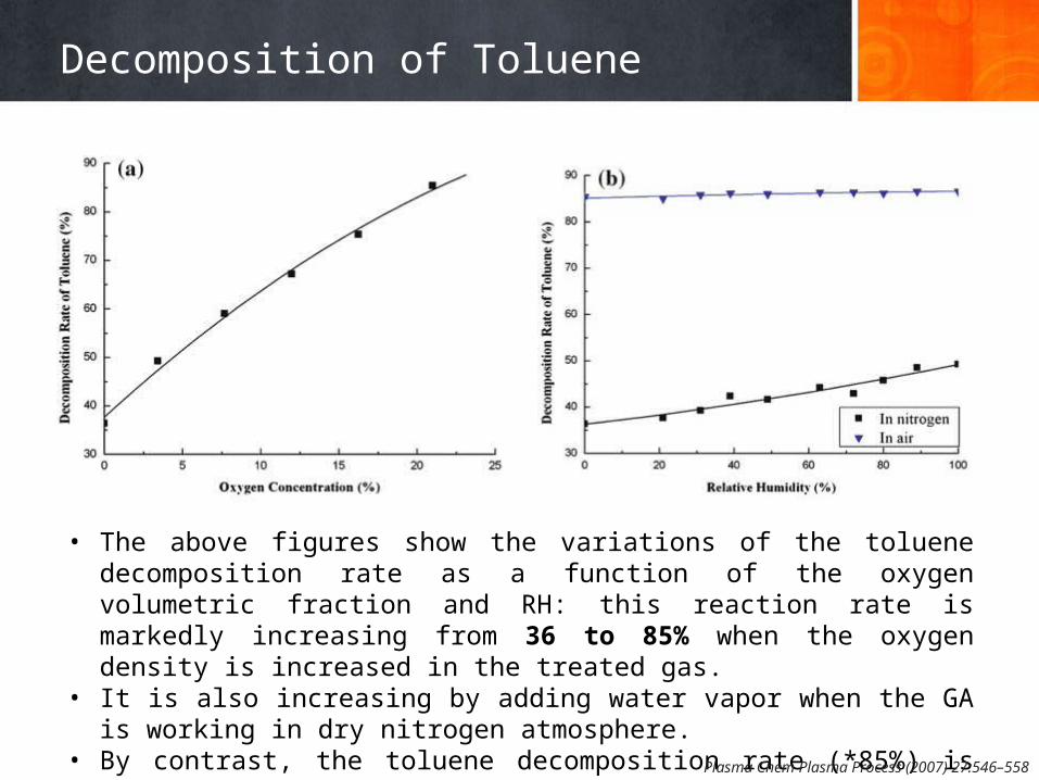
• The above figures show the variations of the toluene decomposition rate as a function of the oxygen volumetric fraction and RH: this reaction rate is markedly increasing from 36 to 85% when the oxygen density is increased in the treated gas.
• It is also increasing by adding water vapor when the GA is working in dry nitrogen atmosphere.
• By contrast, the toluene decomposition rate (*85%) is not obviously affected by the presence of water vapor in air atmosphere.
Plasma Chem Plasma Process (2007) 27:546–558
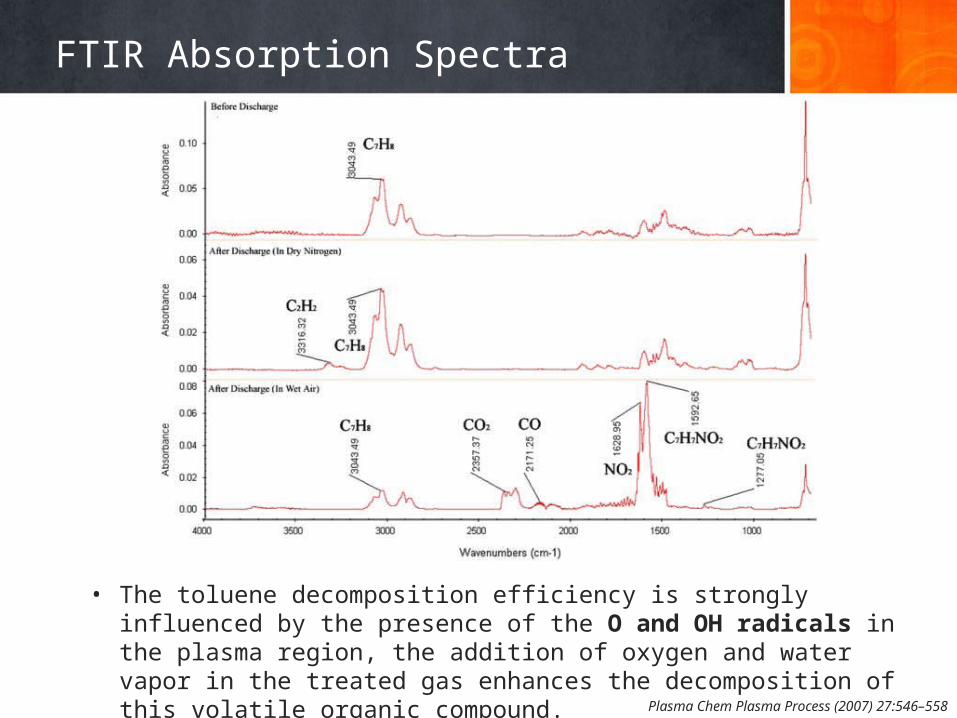
FTIR Absorption Spectra
• The toluene decomposition efficiency is strongly influenced by the presence of the O and OH radicals in the plasma region, the addition of oxygen and water vapor in the treated gas enhances the decomposition of this volatile organic compound.
Plasma Chem Plasma Process (2007) 27:546–558
Spectroscopy tool
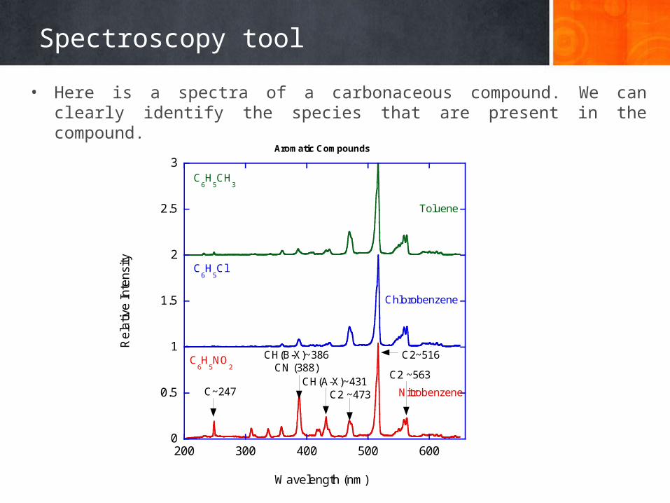
• Here is a spectra of a carbonaceous compound. We can clearly identify the species that are present in the compound.
0
0.5
1
1.5
2
2.5
3
200 300 400 500 600
Aromatic Compounds
Re
lativ
e In
tens
ity
Wavelength (nm)
CH(B-X)~386CN (388)
C2~516
C2 ~473CH(A-X)~431
C2 ~563
Nitrobenzene
Chlorobenzene
Toluene
C~247
C6H
5Cl
C6H
5NO
2
C6H
5CH
3
2 Reactor Design
Comparing different types of plasma configurations, optimizing reactor performance
Reactor Design
Novel Configuration
s
Dielectric Barrier Discharge Reactor
Plasma Process. Polym. 2004, 1, 91–110
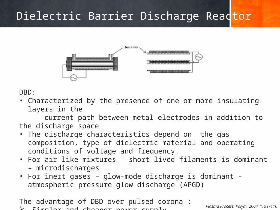
DBD:• Characterized by the presence of one or more insulating layers in the current path between metal electrodes in addition to the discharge space• The discharge characteristics depend on the gas composition, type of dielectric
material and operating conditions of voltage and frequency.• For air-like mixtures- short-lived filaments is dominant – microdischarges• For inert gases – glow-mode discharge is dominant – atmospheric pressure glow
discharge (APGD)
The advantage of DBD over pulsed corona : Simpler and cheaper power supply Can be scaled up without difficulty.
Surface Discharge Reactor
Plasma Process. Polym. 2004, 1, 91–110
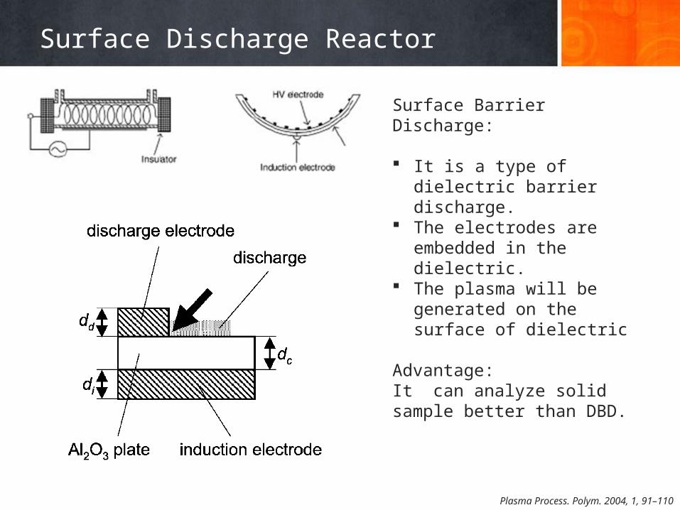
Surface Barrier Discharge:
It is a type of dielectric barrier discharge.
The electrodes are embedded in the dielectric.
The plasma will be generated on the surface of dielectric
Advantage:It can analyze solid sample better than DBD.
Pulsed Corona Reactor
Nonthermal Plasma Processing for Air-Pollution Control: A Historical Review, Current Issues, and Future ProspectsPlasma Process. Polym. 2004, 1, 91–110
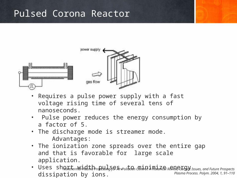
• Requires a pulse power supply with a fast voltage rising time of several tens of nanoseconds.
• Pulse power reduces the energy consumption by a factor of 5.• The discharge mode is streamer mode. Advantages:• The ionization zone spreads over the entire gap and that is favorable
for large scale application.• Uses short width pulses, to minimize energy dissipation by ions.• By controlling pulse frequency , the volume of gas treated can be
controlled
Capillary Plasma Discharge Concept
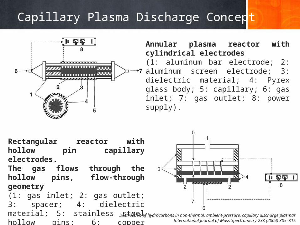
Rectangular reactor with hollow pin capillary electrodes. The gas flows through the hollow pins, flow-through geometry (1: gas inlet; 2: gas outlet; 3: spacer; 4: dielectric material; 5: stainless steel hollow pins; 6: copper electrode; 7: capillary; 8: power supply).
Annular plasma reactor with cylindrical electrodes (1: aluminum bar electrode; 2: aluminum screen electrode; 3: dielectric material; 4: Pyrex glass body; 5: capillary; 6: gas inlet; 7: gas outlet; 8: power supply).
Destruction of hydrocarbons in non-thermal, ambient-pressure, capillary discharge plasmasInternational Journal of Mass Spectrometry 233 (2004) 305–315
Gliding Arc Concept
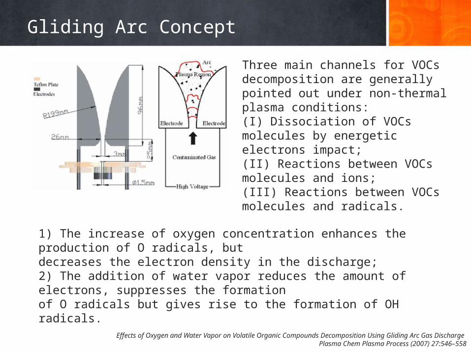
Three main channels for VOCs decomposition are generally pointed out under non-thermal plasma conditions:(I) Dissociation of VOCs molecules by energetic electrons impact;(II) Reactions between VOCs molecules and ions;(III) Reactions between VOCs molecules and radicals.
1) The increase of oxygen concentration enhances the production of O radicals, butdecreases the electron density in the discharge;2) The addition of water vapor reduces the amount of electrons, suppresses the formationof O radicals but gives rise to the formation of OH radicals.
Effects of Oxygen and Water Vapor on Volatile Organic Compounds Decomposition Using Gliding Arc Gas Discharge Plasma Chem Plasma Process (2007) 27:546–558
Packed-bed Reactor
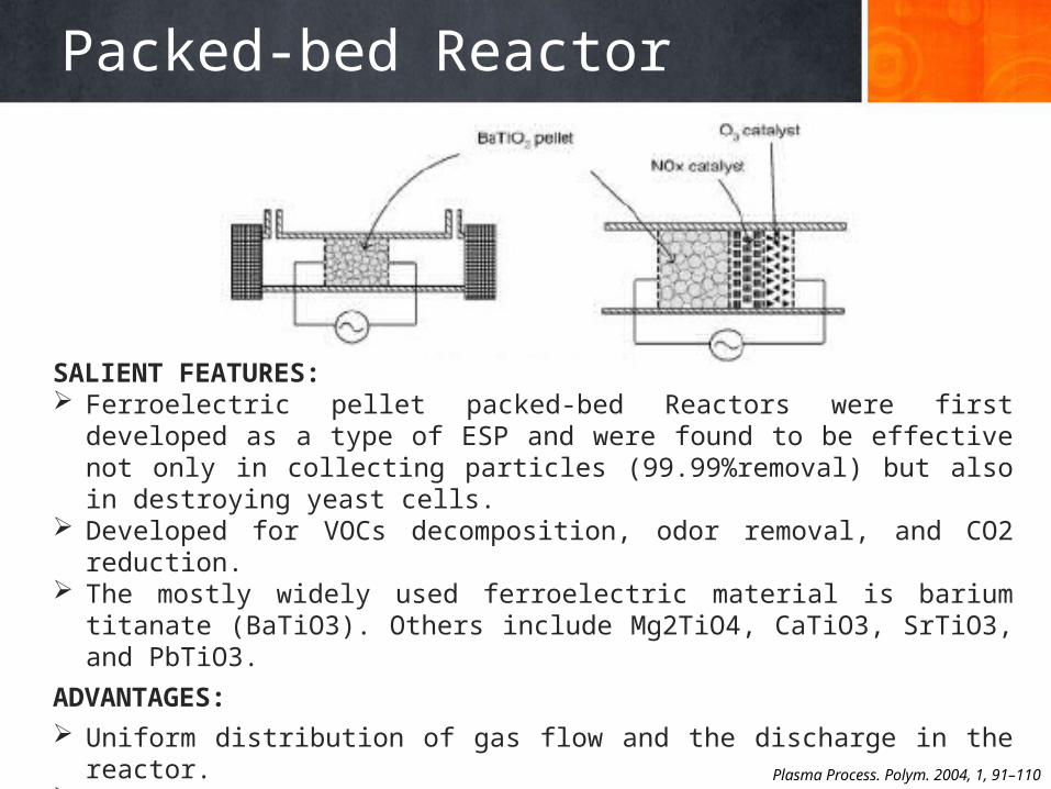
SALIENT FEATURES: Ferroelectric pellet packed-bed Reactors were first developed as a type of ESP and
were found to be effective not only in collecting particles (99.99%removal) but also in destroying yeast cells.
Developed for VOCs decomposition, odor removal, and CO2 reduction. The mostly widely used ferroelectric material is barium titanate (BaTiO3). Others
include Mg2TiO4, CaTiO3, SrTiO3, and PbTiO3.
ADVANTAGES: Uniform distribution of gas flow and the discharge in the reactor. Modification of the reactor to include a catalyst is very easy.
DISADVANTAGES:
Pressure Drop, proper reactor design-energy efficiency.Plasma Process. Polym. 2004, 1, 91–110
Catalyst
Comparing different catalysts, integrating catalyst in to the non-thermal plasma reactor
3
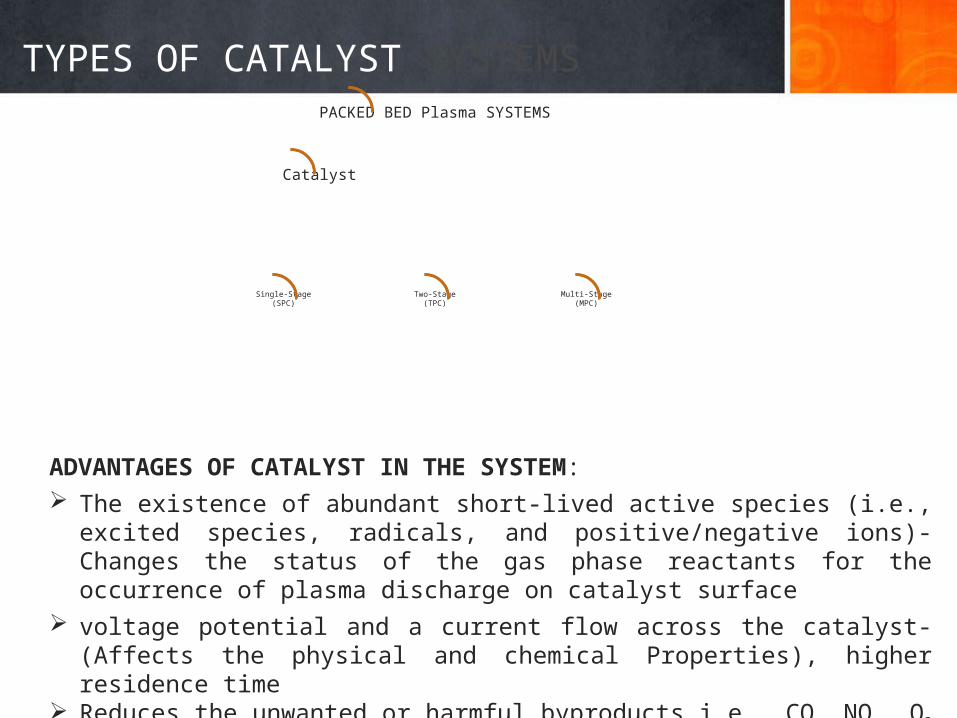
TYPES OF CATALYST SYSTEMSPACKED BED Plasma SYSTEMS
Catalyst
Single-Stage(SPC)
Two-Stage(TPC)
Multi-Stage(MPC)
ADVANTAGES OF CATALYST IN THE SYSTEM: The existence of abundant short-lived active species (i.e., excited species, radicals, and
positive/negative ions)-Changes the status of the gas phase reactants for the occurrence of plasma discharge on catalyst surface
voltage potential and a current flow across the catalyst-(Affects the physical and chemical Properties), higher residence time
Reduces the unwanted or harmful byproducts i.e., CO, NOx, O3 by selectivity of the catalyst
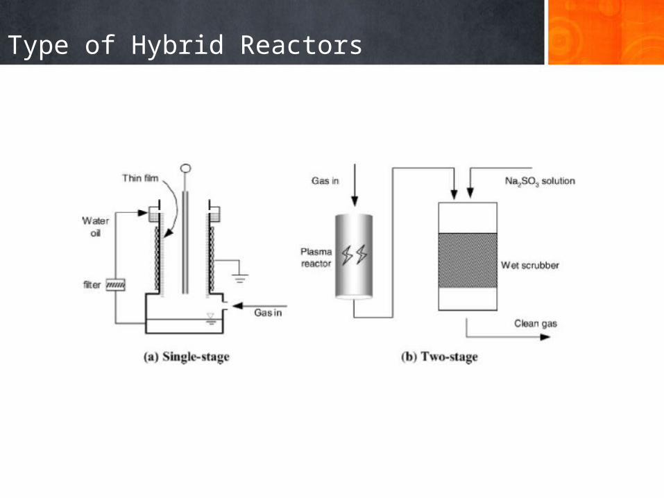
Type of Hybrid Reactors
SPC over TPC & MPC
• SPC- Single stage Plasma Catalysis• TPC- Two stage Plasma Catalysis• MPC- Multistage Plasma Catalysis• Ions and electronically excited species would have de-excited before they
reach the catalyst surface. • The internal energy of the species in rotational state is not sufficient to induce
further reactions.• Although the internal energy of vibrationally excited species is not enough to
induce plasma chemistry reactions, they are the active species produced in plasma with the minimum internal energy to improve catalytic reactions.
• Radicals generally show a much higher sticking coefficient for chemisorption, an essential step of catalytic reactions.
• Deactivation of catalyst in the case of TPC and MPC is easier.
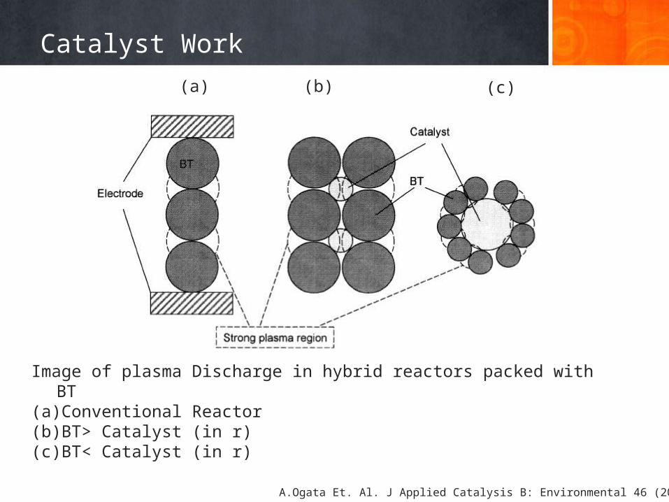
Image of plasma Discharge in hybrid reactors packed with BT (a) Conventional Reactor(b) BT> Catalyst (in r)(c) BT< Catalyst (in r)
Catalyst Work(a) (b) (c)
A.Ogata Et. Al. J Applied Catalysis B: Environmental 46 (2003) 87-93
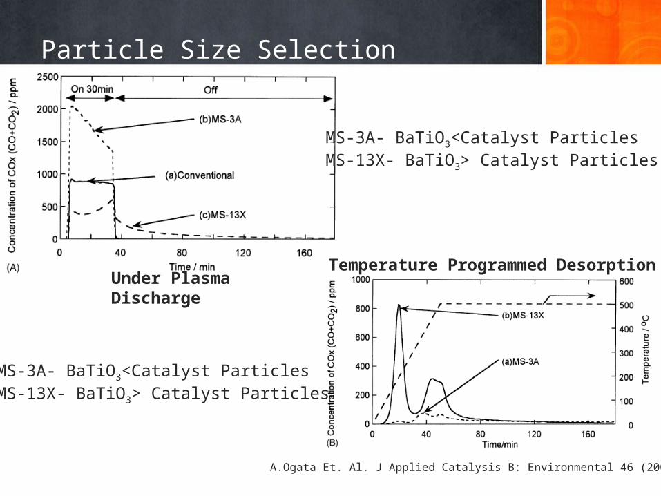
Particle Size Selection
Under Plasma DischargeTemperature Programmed Desorption
MS-3A- BaTiO3<Catalyst ParticlesMS-13X- BaTiO3> Catalyst Particles
MS-3A- BaTiO3<Catalyst ParticlesMS-13X- BaTiO3> Catalyst Particles
A.Ogata Et. Al. J Applied Catalysis B: Environmental 46 (2003) 87-93
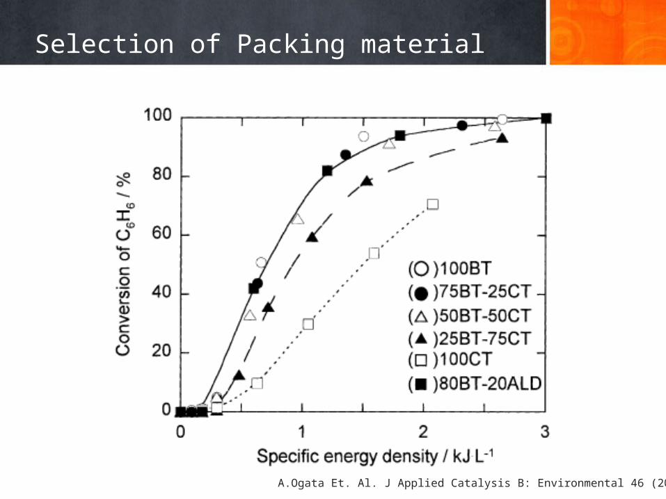
Selection of Packing material
A.Ogata Et. Al. J Applied Catalysis B: Environmental 46 (2003) 87-93
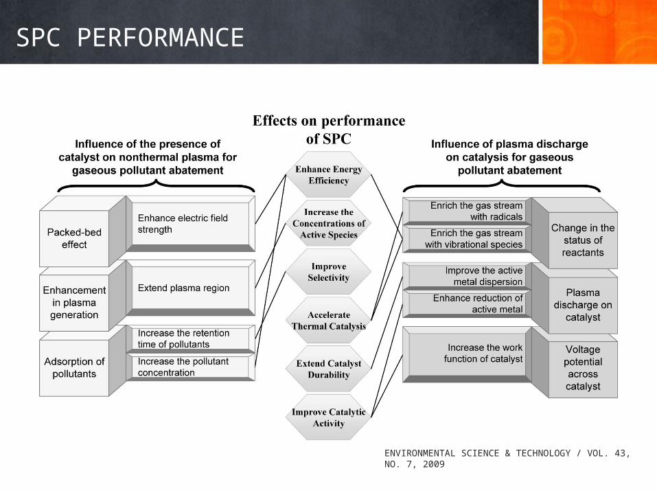
SPC PERFORMANCE
ENVIRONMENTAL SCIENCE & TECHNOLOGY / VOL. 43, NO. 7, 2009
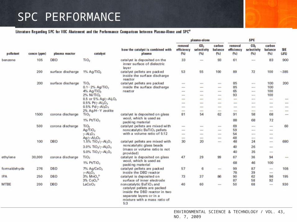
SPC PERFORMANCE
ENVIRONMENTAL SCIENCE & TECHNOLOGY / VOL. 43, NO. 7, 2009
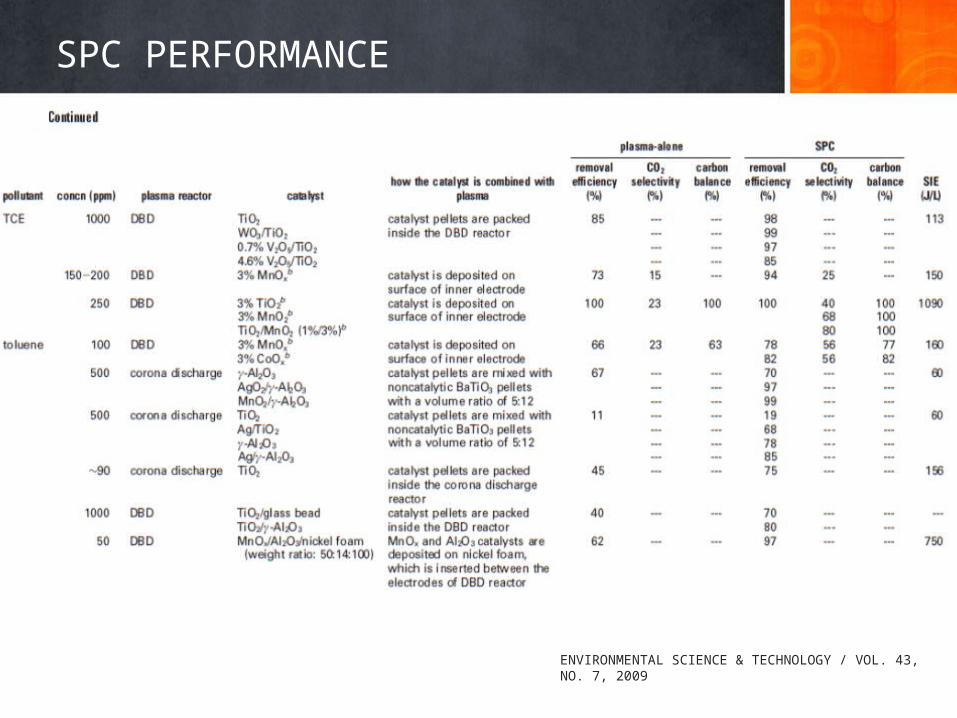
SPC PERFORMANCE
ENVIRONMENTAL SCIENCE & TECHNOLOGY / VOL. 43, NO. 7, 2009
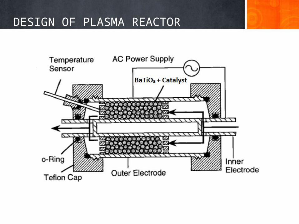
DESIGN OF PLASMA REACTOR
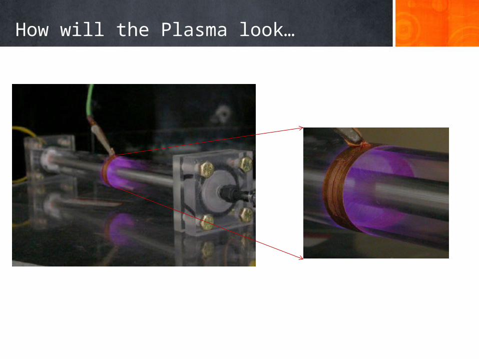
How will the Plasma look…
ASSUMPTIONS
• The porosity(Ɛ) was calculated to be 0.733 assuming there are 5 particles in a cross section of 10mmX 2mm section of the experimental setup. We assume the scaled reactor is also having the same porosity.
• The density(ρ) of the inlet gas was assumed to be 1.251 g/L ( Same as that of air).
• The viscosity(µ) of the inlet gas was assumed to be .01781x10-2 g/(cc.sec).• The flow in the lab scale reactor was laminar flow which is assumed to be
the same in the modeled reactor.• All the particles are assumed to be perfect spheres. Hence sphericity (φs)
is 1.• The target gas flow rate is 2000 L/min.
CALCULATIONS
• EXPERIMENTAL SETUP:Volume of the reactor (V)=(∏/4)*(L)*(do
2-di2)
=31415.926 mm3
=31.415cm3
Porosity (Ɛ) =1-{(vol. fraction of spheres)}= 1-{(n*4*∏*(0.2)3)/(3*31.415)}=.733
Reynolds Number = Rep= {(ρ*Vs*Dp* φs2)/[µ*(1-Ɛ)]}
={[1.251*(.2/60)*(1/25.1327)*.2*1]/(.01781*10-2*(1-.733)}
=0.6978 = Laminar flow
CALCULATIONS
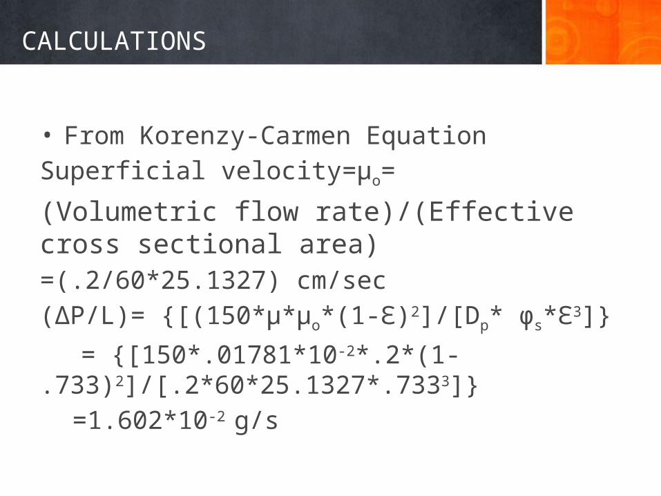
• From Korenzy-Carmen EquationSuperficial velocity=µo=
(Volumetric flow rate)/(Effective cross sectional area)=(.2/60*25.1327) cm/sec(∆P/L)= {[(150*µ*µo*(1-Ɛ)2]/[Dp* φs*Ɛ3]}
= {[150*.01781*10-2*.2*(1-.733)2]/[.2*60*25.1327*.7333]}
=1.602*10-2 g/s
CALCULATIONS
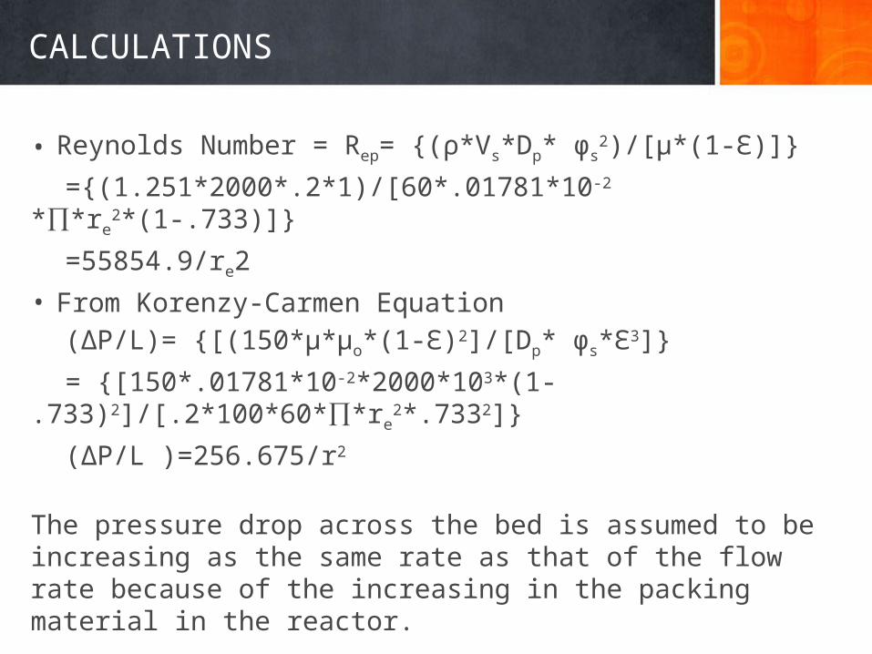
• Reynolds Number = Rep= {(ρ*Vs*Dp* φs2)/[µ*(1-Ɛ)]}
={(1.251*2000*.2*1)/[60*.01781*10-2
*∏*re2*(1-.733)]}
=55854.9/re2• From Korenzy-Carmen Equation
(∆P/L)= {[(150*µ*µo*(1-Ɛ)2]/[Dp* φs*Ɛ3]}
= {[150*.01781*10-2*2000*103*(1-.733)2]/[.2*100*60*∏*re
2*.7332]}
(∆P/L )=256.675/r2
The pressure drop across the bed is assumed to be increasing as the same rate as that of the flow rate because of the increasing in the packing material in the reactor.
CALCULATIONS
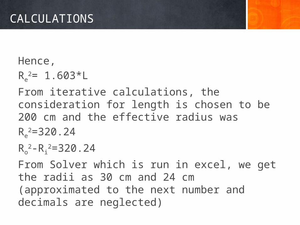
Hence,Re
2= 1.603*L
From iterative calculations, the consideration for length is chosen to be 200 cm and the effective radius was Re
2=320.24
Ro2-Ri
2=320.24
From Solver which is run in excel, we get the radii as 30 cm and 24 cm (approximated to the next number and decimals are neglected)
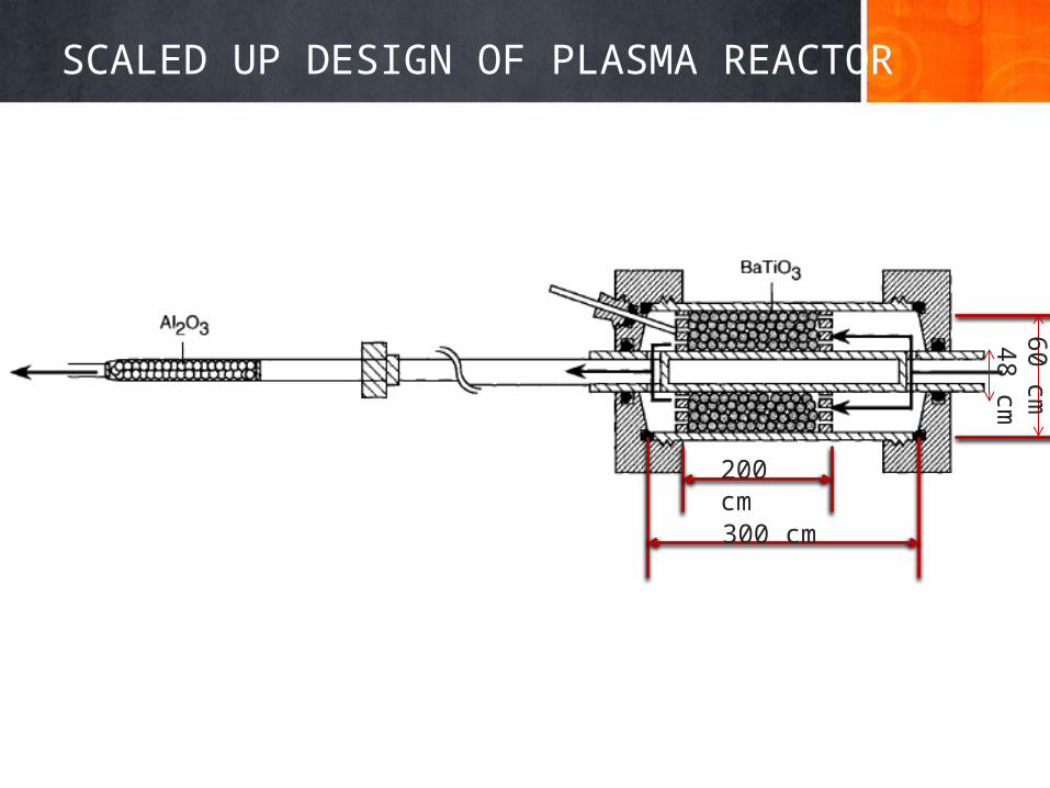
SCALED UP DESIGN OF PLASMA REACTOR60 cm48 cm
200 cm
300 cm
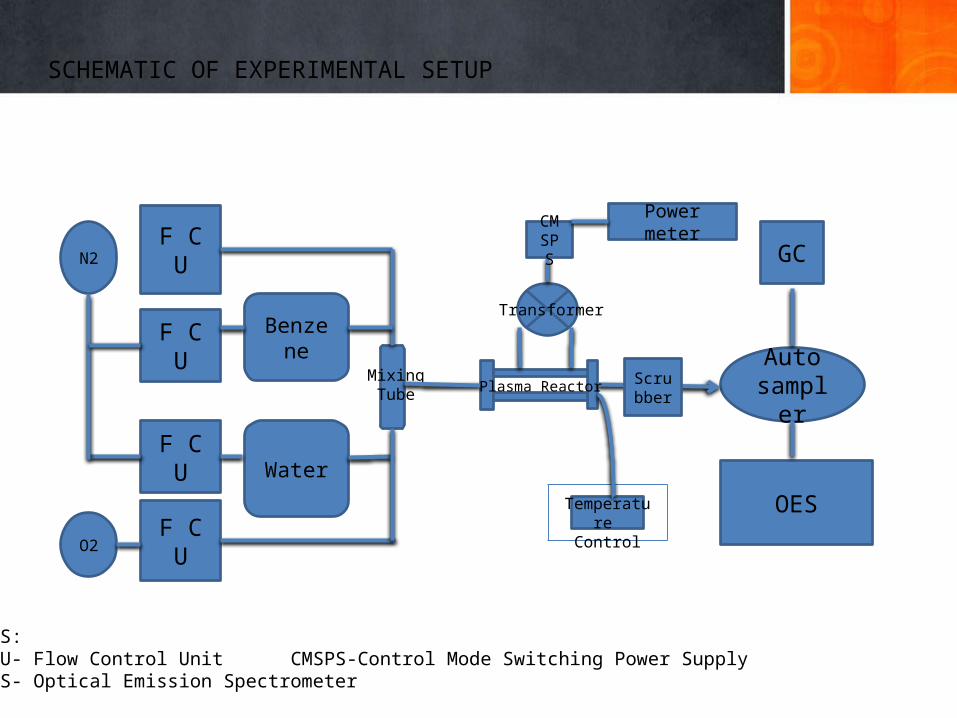
SCHEMATIC OF EXPERIMENTAL SETUP
N2
O2
F C U
F C U
F C U
F C U
Benzene
Water
Power meter
Auto sampler
GC
OES
Transformer
Mixing Tube Plasma Reactor
TERMS:F C U- Flow Control Unit CMSPS-Control Mode Switching Power SupplyO E S- Optical Emission Spectrometer
Temperature Control
CMSPS
Scrubber
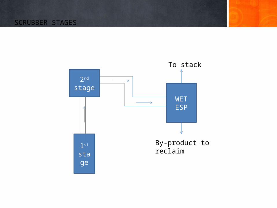
SCRUBBER STAGES
2nd stage
1st stage
WET ESP
To stack
By-product to reclaim
Energy & sensitivity analysis, cost estimates
4 Energy & Economic Analysis
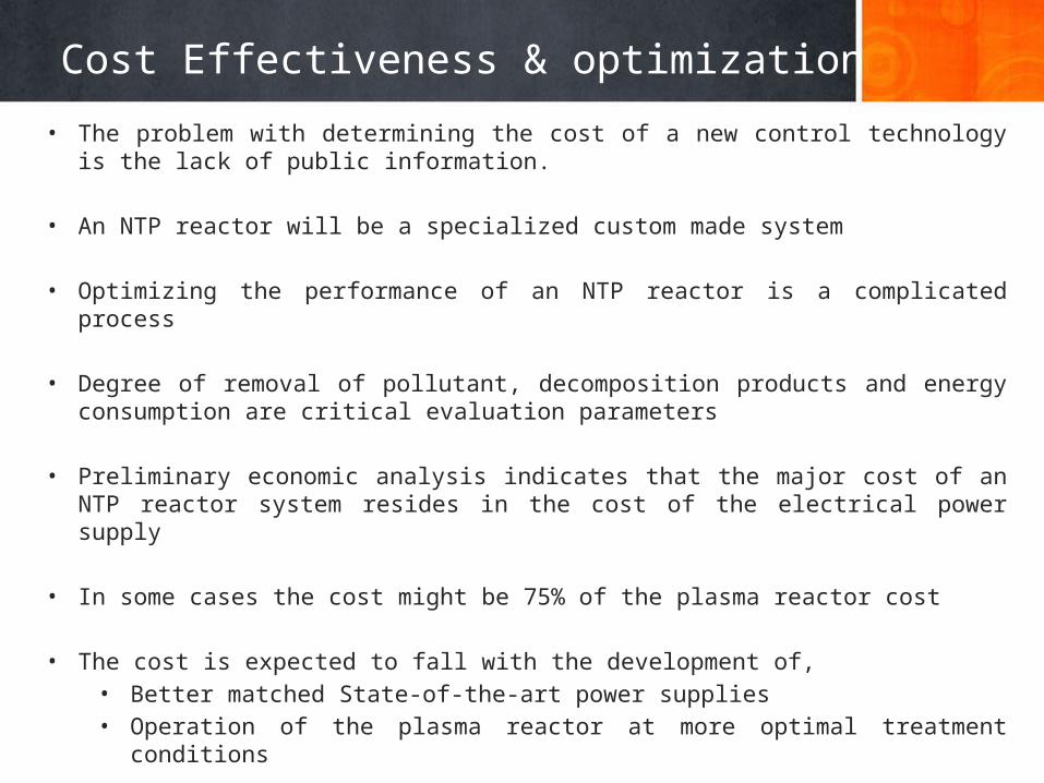
Cost Effectiveness & optimization
• The problem with determining the cost of a new control technology is the lack of public information.
• An NTP reactor will be a specialized custom made system
• Optimizing the performance of an NTP reactor is a complicated process
• Degree of removal of pollutant, decomposition products and energy consumption are critical evaluation parameters
• Preliminary economic analysis indicates that the major cost of an NTP reactor system resides in the cost of the electrical power supply
• In some cases the cost might be 75% of the plasma reactor cost
• The cost is expected to fall with the development of, • Better matched State-of-the-art power supplies • Operation of the plasma reactor at more optimal treatment conditions
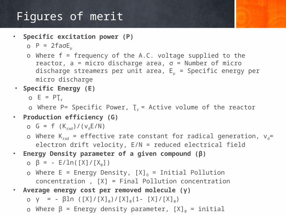
Figures of merit
• Specific excitation power (P) o P = 2faσEµ o Where f = frequency of the A.C. voltage supplied to the reactor, a = micro discharge area, σ =
Number of micro discharge streamers per unit area, Eµ = Specific energy per micro discharge• Specific Energy (E)
o E = PƮr
o Where P= Specific Power, Ʈr = Active volume of the reactor• Production efficiency (G)
o G = f (Krad)/(vdE/N)o Where Krad = effective rate constant for radical generation, vd= electron drift velocity, E/N =
reduced electrical field• Energy Density parameter of a given compound (β)
o β = - E/ln([X]/[X0])o Where E = Energy Density, [X]O = Initial Pollution concentration , [X] = Final Pollution
concentration• Average energy cost per removed molecule (γ)
o γ = - βln ([X]/[X]0)/[X]0(1- [X]/[X]0)o Where β = Energy density parameter, [X]0 = initial concentration, [X] = Final concentration
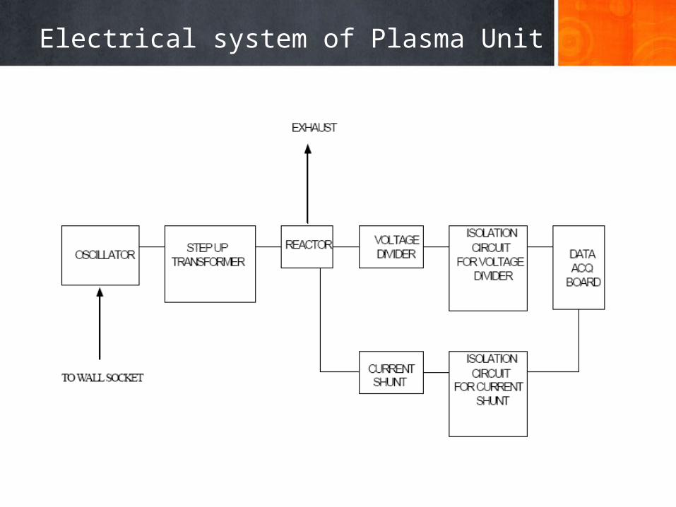
Electrical system of Plasma Unit
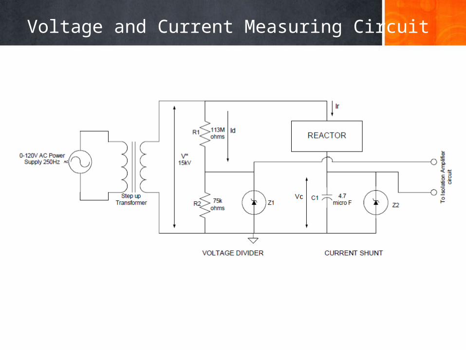
Voltage and Current Measuring Circuit
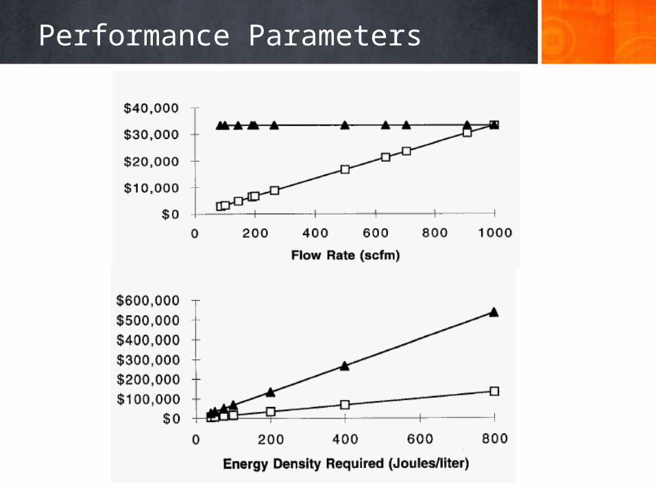
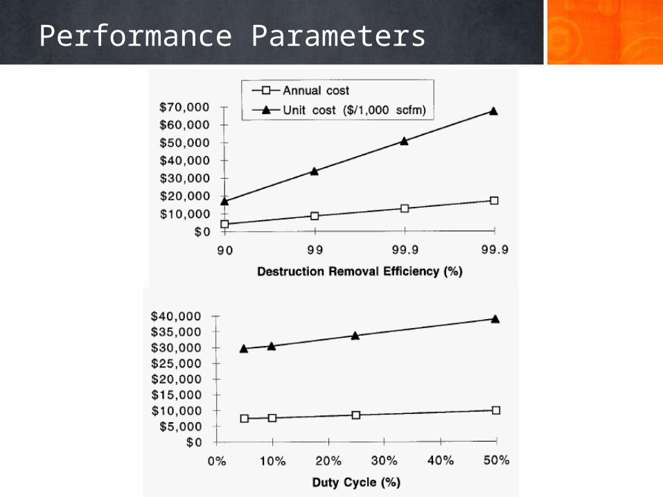
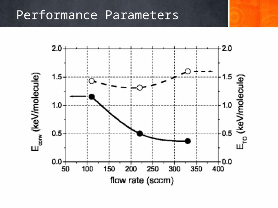
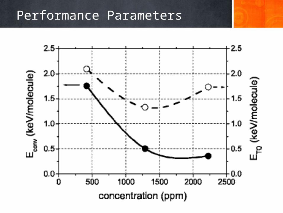
Sensitivity Analysis• A technique used to determine how different values of an independent variable will impact a
particular dependent variable under a given set of assumptions
• This technique is used within specific boundaries that will depend on one or more input variables
• The four major parameters that influence the NTP reactor cost of ownership are• Flow Rate• Energy density (power requirement)• Target effluent concentration (DRE)• Duty Cycle (Percentage of time that exhaust output is actually being emitted)
• The cells and support equipment are made from simple inexpensive materials and are minor components of capital cost
• Total annual costs and unit costs are dependent upon values given for the important 4 parameters
• Due to the dynamic influence of these parameters on the cost, a sensitivity analysis is essential showing their relationship to the cost of ownership
Performance Parameters
Performance Parameters
Performance Parameters
Performance Parameters
Performance Parameters
Performance Parameters
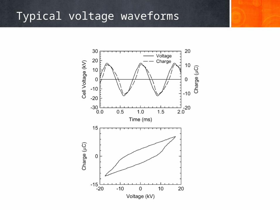
Typical voltage waveforms
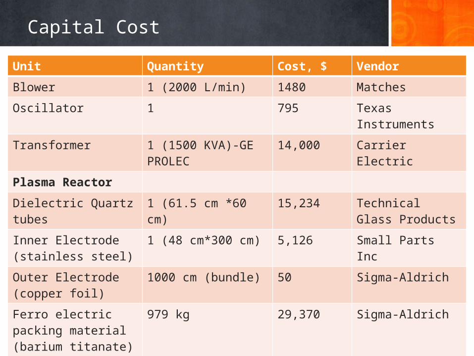
Capital Cost
Unit Quantity Cost, $ Vendor
Blower 1 (2000 L/min) 1480 Matches
Oscillator 1 795 Texas Instruments
Transformer 1 (1500 KVA)-GE PROLEC 14,000 Carrier Electric
Plasma Reactor
Dielectric Quartz tubes 1 (61.5 cm *60 cm) 15,234 Technical Glass Products
Inner Electrode (stainless steel)
1 (48 cm*300 cm) 5,126 Small Parts Inc
Outer Electrode (copper foil)
1000 cm (bundle) 50 Sigma-Aldrich
Ferro electric packing material (barium titanate)
979 kg 29,370 Sigma-Aldrich
Fiberglass case for the reactor
1 (62 cm* 310 cm) 200 Niemiac Marine Inc
Alumina 244.8 kg 10,184 Sigma Aldrich
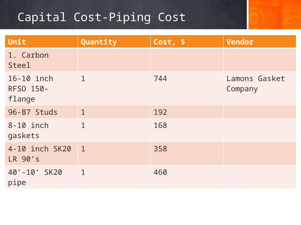
Capital Cost-Piping Cost
Unit Quantity Cost, $ Vendor
1. Carbon Steel
16-10 inch RFSO 150-flange
1 744 Lamons Gasket Company
96-B7 Studs 1 192
8-10 inch gaskets 1 168
4-10 inch SK20 LR 90’s
1 358
40’-10’ SK20 pipe 1 460
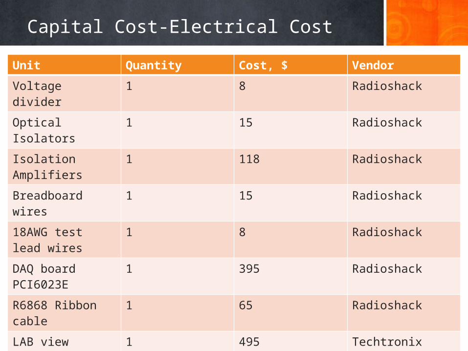
Capital Cost-Electrical Cost
Unit Quantity Cost, $ Vendor
Voltage divider 1 8 Radioshack
Optical Isolators 1 15 Radioshack
Isolation Amplifiers 1 118 Radioshack
Breadboard wires 1 15 Radioshack
18AWG test lead wires
1 8 Radioshack
DAQ board PCI6023E 1 395 Radioshack
R6868 Ribbon cable 1 65 Radioshack
LAB view software 1 495 Techtronix
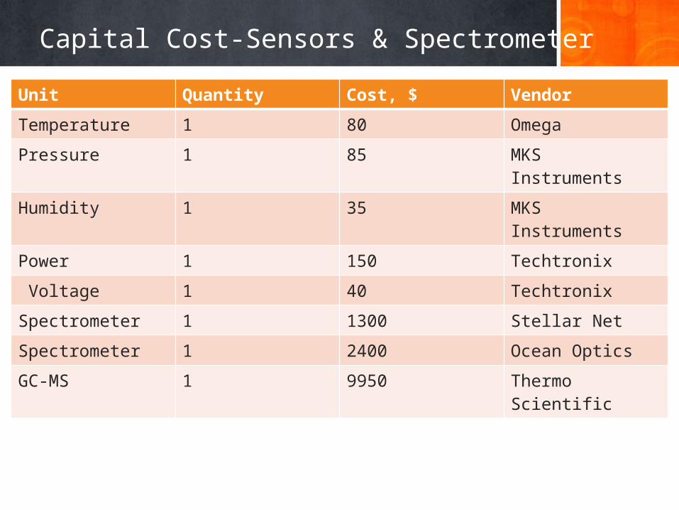
Capital Cost-Sensors & Spectrometer
Unit Quantity Cost, $ Vendor
Temperature 1 80 Omega
Pressure 1 85 MKS Instruments
Humidity 1 35 MKS Instruments
Power 1 150 Techtronix
Voltage 1 40 Techtronix
Spectrometer 1 1300 Stellar Net
Spectrometer 1 2400 Ocean Optics
GC-MS 1 9950 Thermo Scientific
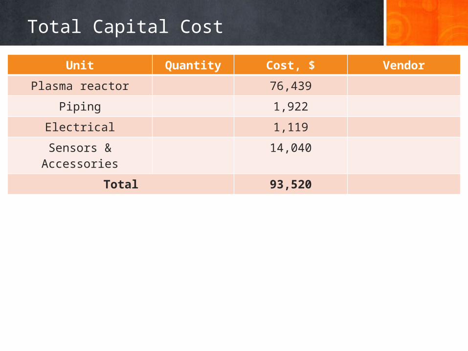
Total Capital Cost
Unit Quantity Cost, $ Vendor
Plasma reactor 76,439
Piping 1,922
Electrical 1,119
Sensors & Accessories 14,040
Total 93,520
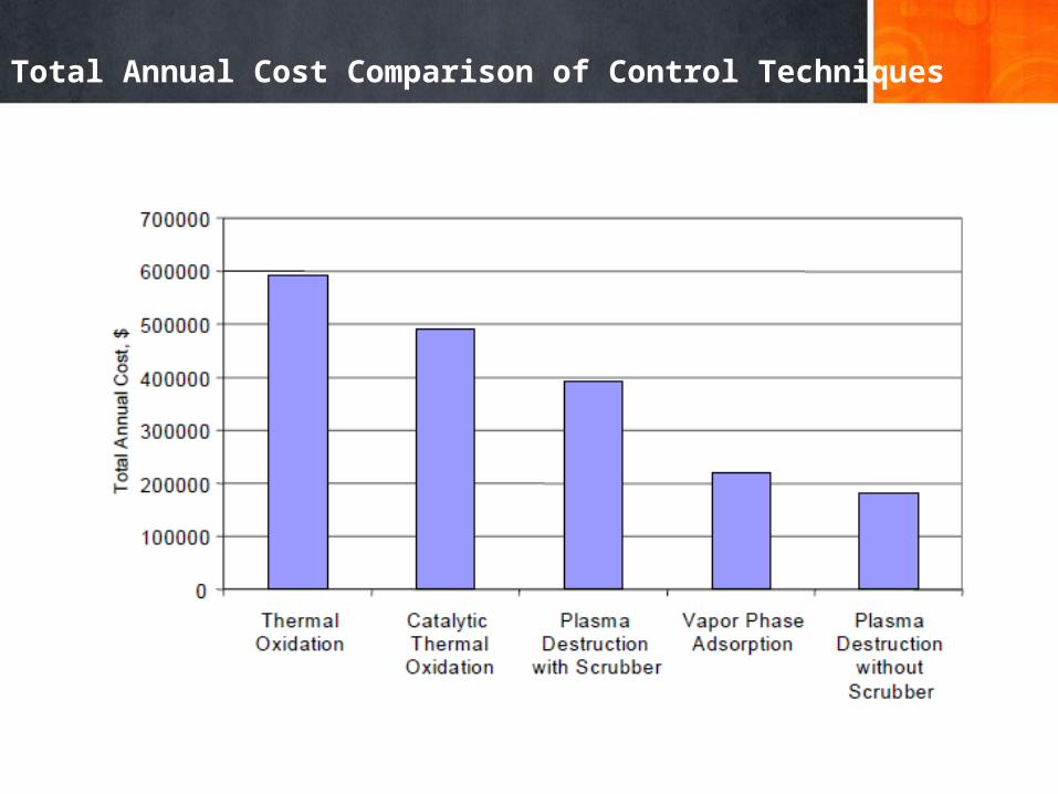
Total Annual Cost Comparison of Control Techniques
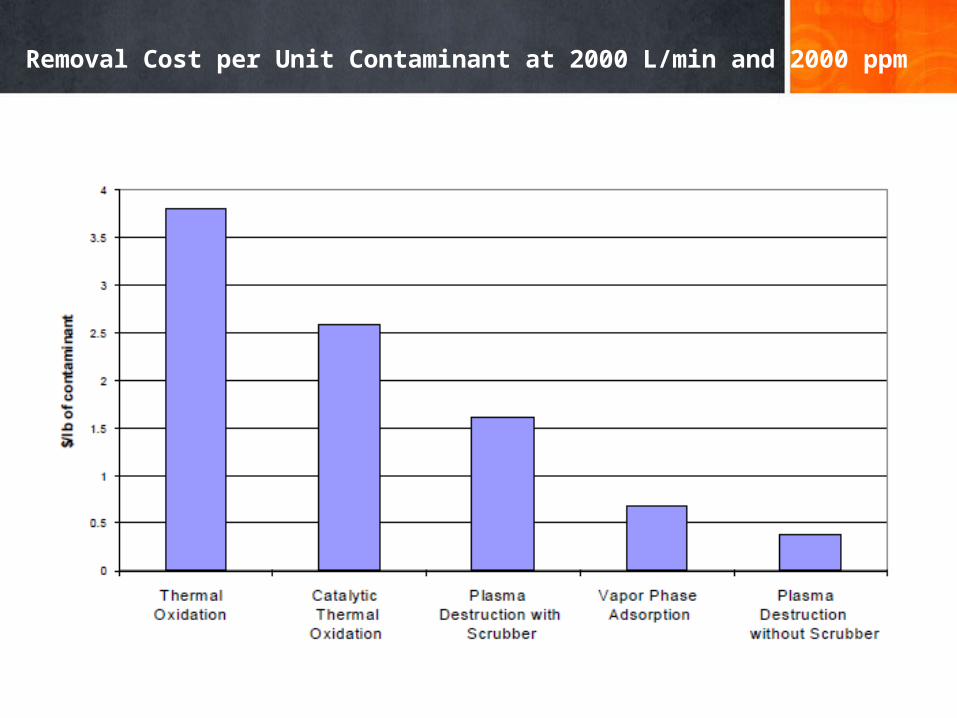
Removal Cost per Unit Contaminant at 2000 L/min and 2000 ppm
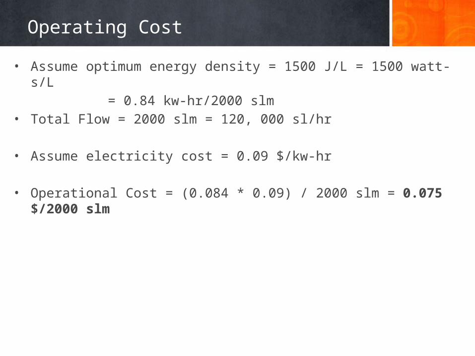
Operating Cost
• Assume optimum energy density = 1500 J/L = 1500 watt-s/L= 0.84 kw-hr/2000 slm
• Total Flow = 2000 slm = 120, 000 sl/hr
• Assume electricity cost = 0.09 $/kw-hr
• Operational Cost = (0.084 * 0.09) / 2000 slm = 0.075 $/2000 slm
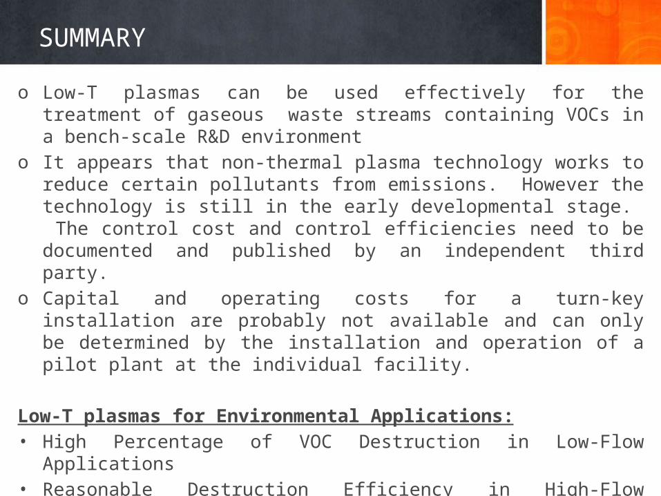
SUMMARY
o Low-T plasmas can be used effectively for the treatment of gaseous waste streams containing VOCs in a bench-scale R&D environment
o It appears that non-thermal plasma technology works to reduce certain pollutants from emissions. However the technology is still in the early developmental stage. The control cost and control efficiencies need to be documented and published by an independent third party.
o Capital and operating costs for a turn-key installation are probably not available and can only be determined by the installation and operation of a pilot plant at the individual facility.
Low-T plasmas for Environmental Applications:• High Percentage of VOC Destruction in Low-Flow Applications• Reasonable Destruction Efficiency in High-Flow Applications • Extensive Characterization of By-Products • High Level of Carbon Closure
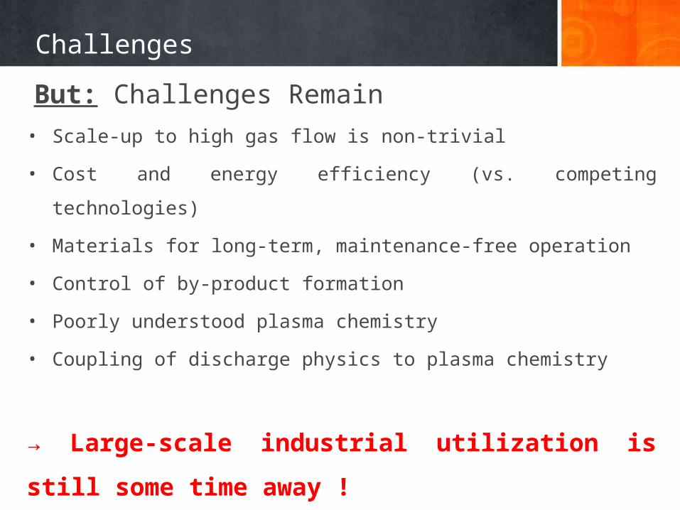
Challenges
But: Challenges Remain• Scale-up to high gas flow is non-trivial
• Cost and energy efficiency (vs. competing technologies)
• Materials for long-term, maintenance-free operation
• Control of by-product formation
• Poorly understood plasma chemistry
• Coupling of discharge physics to plasma chemistry
→ Large-scale industrial utilization is still some time away !
References
1. B M Penetrantey, M C Hsiaoy, J N Bardsleyy, B T Merritty, G E Vogtliny, A Kuthiz, C P Burkhartz and J R Baylessz Plasma Sources Sci. Technol. 6 (1997) 251–259
2. Hyun-Ha Kim Plasma Process. Polym. 2004, 1, 91–1103. A. Koutsospyros, S.-M. Yin, C. Christodoulatos, K. Becker International Journal of Mass Spectrometry 233
(2004) 305–3154. R. G. Tonkyn, S. E. Barlow, T. M. Orlando J. Appl. Phys. 80 (9), 1 November 19965. Zh. Bo, J. H. Yan, X. D. Li, Y. Chi, K. F. Cen, B. G. Che´ron Plasma Chem Plasma Process (2007) 27:546–5586. Hyun-Ha Kim, Seung-Min Oh, Atsushi Ogata, Shigeru Futamura Applied Catalysis B: Environmental 56 (2005)
213–2207. Hui-Xian Ding, Ai-Min Zhu, Fu-Gong Lu, Yong Xu, Jing Zhang, Xue-Feng Yang J. Phys. D: Appl. Phys. 39 (2006)
3603–36088. B. M. Penetrante, R. M. Brusasco, B. T. Merritt and G. E. Vogtlin Pure Appl. Chem., Vol. 71, No. 10, pp.
1829±1835, 19999. H H Kim, K Takashima, S Katsura and A Mizuno J. Phys. D: Appl. Phys. 34 (2001) 604–61310. Jim Van Durme, Jo Dewulf, Christophe Leys, Herman Van Langenhove Applied Catalysis B: Environmental 78
(2008) 324–33311. Hyun-Ha Kim, Seung-Min Oh, Atsushi Ogata, Shigeru Futamura Catalysis Letters Vol. 96, Nos. 3–4, July 2004
(2004)
References
12. A l i c e M. H a r l i n g, D a v i d J. G l o v e r, J. C h r i s t o p h e r w h i t e h e a d, K u i z h a n g Environ. Sci. Technol. 2008, 42, 4546–4550
13. Duan Li, Daisuke Yakushiji, Seiji Kanazawa, Toshikazu Ohkubo, Yukiharu Nomoto 0-7803-7116-X/01/$10.00 (C) 2001 IEEE
14. R. G. Tonkyn, S. E. Barlow, T. M. Orlando J. Appl. Phys. 80 (9), 1 November 199615. Atsushi Ogata, Daisuke Ito, Koichi Mizuno, Satoshi Kushiyama, Arkadi Gal, Toshiaki Yamamoto Applied Catalysis
A: General 236 (2002) 9–1516. Applied Catalysis A: General 236 (2002) 9–15 J. Appl. Phys., Vol. 85, No. 1, 1 January 199917. Monica Magureanu, Nicolae B. Mandache, Pierre Eloy, Eric M. Gaigneaux, Vasile I. Parvulescu Applied Catalysis
B: Environmental 61 (2005) 12–2018. H. Huang, L. Tang 2006 Published by Elsevier Ltd.19. R. G. Tonkyn, S. E. Barlow, and T. M. Orlando J. Appl. Phys. 80 (9), 1 November 199620. Hyun-Ha Kim, Seung-Min Oh, Atsushi Ogata, Shigeru Futamura Catalysis Letters Vol. 96, Nos. 3–4, July 2004
(2004)21. R. Rudolph, K.-P. Francke, H. Miessner 0272-4324 02 0900-0401 2002 Plenum Publishing Corporation22. W. Mista, R. Kacprzyk Catalysis Today 137 (2008) 345–34923. Ch. Subrahmanyam, M. Magureanu, A. Renken, L. Kiwi-Minsker Applied Catalysis B: Environmental 65 (2006)
150–15624. K. Moustakas, D. Fatta, S. Malamis, K. Haralambous, M. Loizidou Journal of Hazardous Materials B123 (2005)
120–126

THANK YOU.