Embed Size (px)
Citation preview
Dec 11, 2008 S. Kahn -- Muon Collider Detector Backgrounds
1
Detector Backgrounds in a Muon Collider
Steve KahnMuons Inc.
Muon Collider Design WorkshopDec 11, 2008

Dec 11, 2008 S. Kahn -- Muon Collider Detector Backgrounds
2
Introduction
• This talk is a review of previous presentations on muon collider detector backgrounds. Nothing presented here is new. A large fraction of the the detector background studies was performed by Iuliu Stumer and Nikolai Mokhov.
• I will try to convince you that you can do physics at a Muon Collider.– The backgrounds encountered are certainly worse than an ee– collider,
but they are no worse and probably better than that expected at the LHC and the LHC will produce physics in that environment!
• References:– Snowmas 1996 Feasibility Study– Status Report published in Phys. Rev. AB(1999)– Highest Energy Muon Collider Workshop (Montauk, 1999)– Rosario Muon Collider Workshop (May 1997)– UCLA Workshop (July 1997) Collider Conference, San Francisco (Dec 1997)
Dec 11, 2008 S. Kahn -- Muon Collider Detector Backgrounds
3
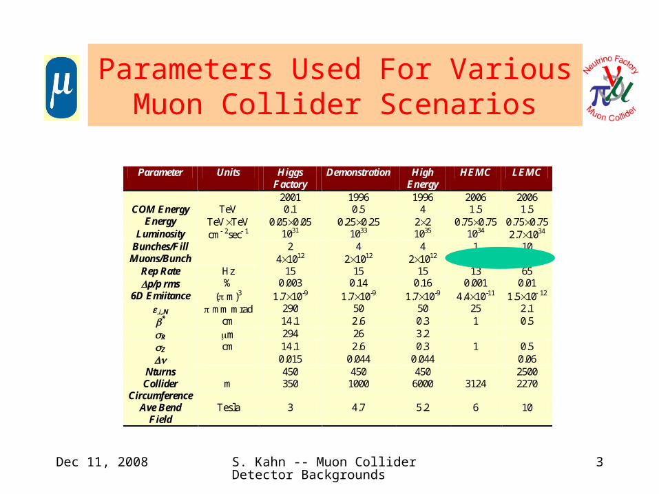
Parameters Used For Various Muon Collider Scenarios
Parameter Units Higgs Factory
Demonstration High Energy
HEMC LEMC
2001 1996 1996 2006 2006 COM Energy TeV 0.1 0.5 4 1.5 1.5
Energy TeVTeV 0.050.05 0.250.25 22 0.750.75 0.750.75 Luminosity cm 2sec 1 1031 1033 1035 1034 2.71034
Bunches/Fill 2 4 4 1 10 Muons/Bunch 41012 21012 21012 21012 1011
Rep Rate Hz 15 15 15 13 65 p/p rms % 0.003 0.14 0.16 0.001 0.01
6D Emiitance ( m)3 1.710-9 1.710-9 1.710-9 4.410-11 1.510 12
,N mm mrad 290 50 50 25 2.1 * cm 14.1 2.6 0.3 1 0.5 R m 294 26 3.2 Z cm 14.1 2.6 0.3 1 0.5 0.015 0.044 0.044 0.06
Nturns 450 450 450 2500 Collider
Circumference m 350 1000 6000 3124 2270
Ave Bend Field
Tesla 3 4.7 5.2 6 10
Dec 11, 2008 S. Kahn -- Muon Collider Detector Backgrounds
4
Background Sources
• Muon Decay Background– Electron Showers from high energy electrons.
• Lepto-production of hadrons not included in studies.– Not important for 22 TeV or smaller colliders.
– Bremsstrahlung Radiation for decay electrons in magnetic fields.– Photonuclear Interactions
• Source of hadrons background.– Bethe-Heitler muon production.
• Beam Halo– Beam Scraping at 180° from IP to reduce halo. Could it cause some?– Collider sources such as magnet misalignments.
• Beam-Beam Interactions.– Believed to be small.

Dec 11, 2008 S. Kahn -- Muon Collider Detector Backgrounds
5
Muon Decay Backgrounds
• Muon decay backgrounds are expected to be high (see table)• The effort to minimize the backgrounds will have strong influence on
– Design of the Detector– Design of the Final Focus for the IR– The IR design itself
• If the per bunch can be reduced as we believe can be done for the LEMC, the detector backgrounds will also be reduced.
– An order of magnitude reduction is a blessing.– Most of the numbers presented in this talk will refer to the earlier designs with
larger numbers of muons per bunch. The results should be scaleable.
Collider per bunch Decays/meter
50 50 GeV 4 1012 2.6 107 250 250 GeV 2 1012 2.6 106
2 2 TeV 2 1012 3.2 105 2.5 2.5 TeV LEMC 1.6 1011 2.0 104
Dec 11, 2008 S. Kahn -- Muon Collider Detector Backgrounds
6
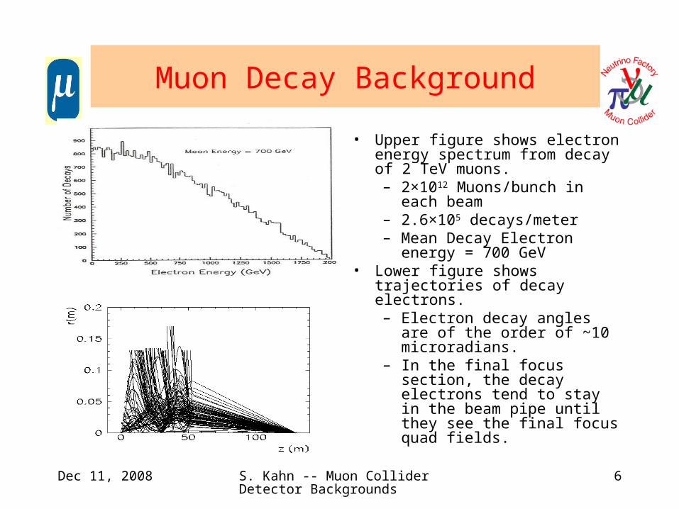
Muon Decay Background
• Upper figure shows electron energy spectrum from decay of 2 TeV muons.– 2×10¹² Muons/bunch in each
beam– 2.6×10⁵ decays/meter– Mean Decay Electron energy =
700 GeV• Lower figure shows trajectories of
decay electrons.– Electron decay angles are of
the order of ~10 microradians.– In the final focus section, the
decay electrons tend to stay in the beam pipe until they see the final focus quad fields.

Dec 11, 2008 S. Kahn -- Muon Collider Detector Backgrounds
7
Strawman Detector Concept for a Muon Collider
Dec 11, 2008 S. Kahn -- Muon Collider Detector Backgrounds
8
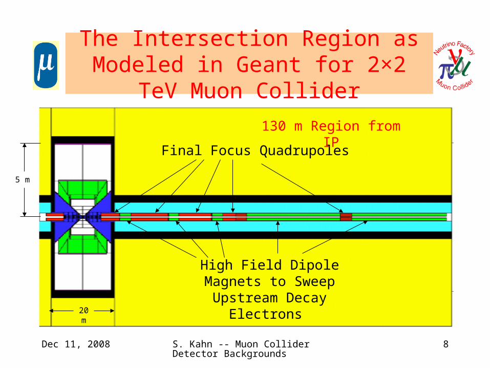
The Intersection Region as Modeled in Geant for 2×2 TeV Muon Collider
Final Focus Quadrupoles
130 m Region from IP
High Field Dipole Magnets to Sweep Upstream Decay
Electrons 20 m
5 m
Dec 11, 2008 S. Kahn -- Muon Collider Detector Backgrounds
9
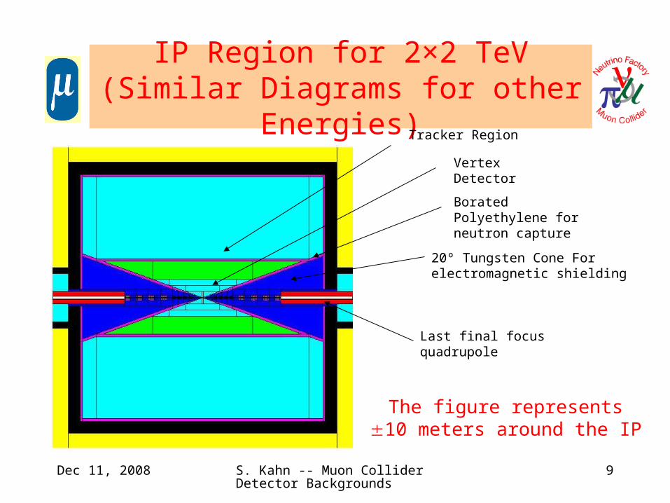
IP Region for 2×2 TeV(Similar Diagrams for other Energies)
20º Tungsten Cone For electromagnetic shielding
Borated Polyethylene for neutron capture
Vertex Detector
Tracker Region
Last final focus quadrupole
The figure represents 10 meters around the IP
Dec 11, 2008 S. Kahn -- Muon Collider Detector Backgrounds
10
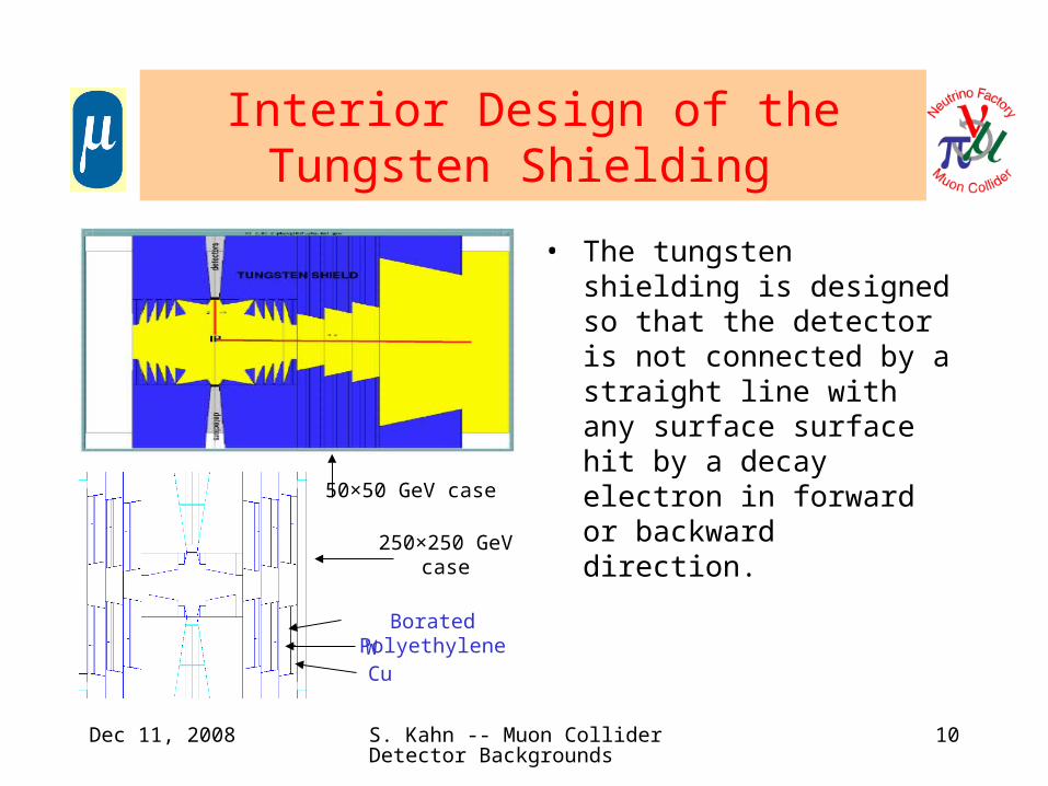
Interior Design of the Tungsten Shielding
• The tungsten shielding is designed so that the detector is not connected by a straight line with any surface surface hit by a decay electron in forward or backward direction.
50×50 GeV case
250×250 GeV case
WCu
Borated Polyethylene
Dec 11, 2008 S. Kahn -- Muon Collider Detector Backgrounds
11
Summarizing Shielding Configuration to Reduce Backgrounds
• 20 degree conical tungsten shield in forward/backward direction.
• Expanding inner cone from minimum aperture point is set at 4 beam size.
• Inverse cone between IP and minimum aperture point is set to 4 beam divergence.
– Designed so detector does not see surfaces struck by incident electrons.
• Inner surface of each shield shaped into collimating steps and slopes to maximize absorption of electron showers.
– Reduces low energy electrons in beam pipe.
• High field sweeping dipole magnets placed upstream of first quadrupole. These dipoles have collimators inside to sweep decay electrons in advance of final collimation.

Dec 11, 2008 S. Kahn -- Muon Collider Detector Backgrounds
12
Electrons in the Intersection Region
• Top figure shows the expanded view of the region near the IP.
– The lines represent electrons from a random sample of muon decays.
– Electrons are removed by interior collimation surfaces.
• The bottom figure shows a detailed view of the IR.
– Electrons from a random set of muon decays.
– Electrons do not make it into the detector region.

Dec 11, 2008 S. Kahn -- Muon Collider Detector Backgrounds
13
IP Configuration Parameters
Parameter 50×50 GeV 250×250 GeV 2×2 TeV
Shield Angle 20º 20º 20º
Open Space to IP
6 cm 3 cm 3 cm
Min Aperture Point
80 cm 1.1 m 1.1 m
Riris 0.8 cm 0.5 cm
Distance to First Quad
7 m 8 m 6.5 m
Dec 11, 2008 S. Kahn -- Muon Collider Detector Backgrounds
14
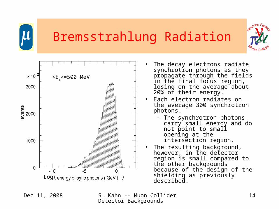
Bremsstrahlung Radiation
• The decay electrons radiate synchrotron photons as they propagate through the fields in the final focus region, losing on the average about 20% of their energy.
• Each electron radiates on the average 300 synchrotron photons.– The synchrotron photons carry
small energy and do not point to small opening at the intersection region.
• The resulting background, however, in the detector region is small compared to the other backgrounds because of the design of the shielding as previously described.Log( )
<E>=500 MeV

Dec 11, 2008 S. Kahn -- Muon Collider Detector Backgrounds
15
Incoherent Pair Production
• Incoherent pair production from ee can be significant for high energy muon colliders.
– Estimated cross section of 10 mb giving 3×10⁴ electron pairs per bunch crossing.
– The electron pairs have small transverse momentum, but the on-coming beam can deflect them towards the detector.
– Figures show examples of electron pairs tracked near the detector in the presence of the detector solenoid field.
– With a 2 Tesla field, only 10% of electrons make it 10 cm into the detector. With 4 Tesla field no electrons reach 10 cm.

Dec 11, 2008 S. Kahn -- Muon Collider Detector Backgrounds
16
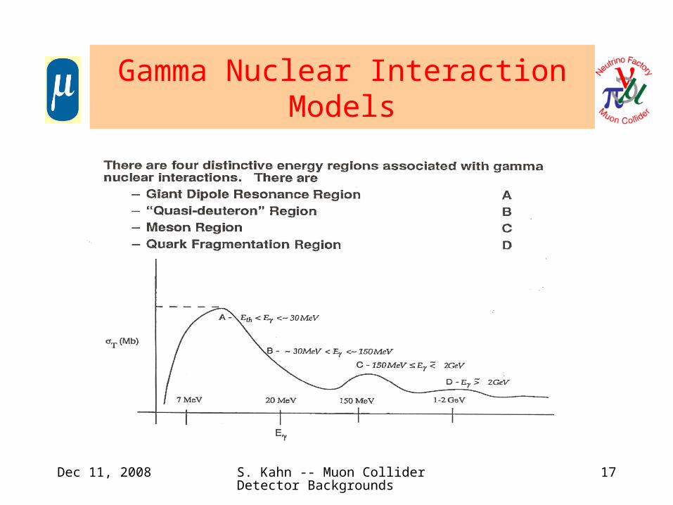
Photonuclear Interactions
• This is the primary source of hadron background.• The probability for photo production is small relative to other processes.
– Large numbers of photons released per crossing make this an important background.
• Different mechanisms in different energy bands:– Giant Dipole Resonance Region
• 5<E<30 MeV• Produce ~1 neutron
– Quasi-Deuteron Region• 30<E< 150 MeV• Produce ~1 neutron
– Baryon Resonance Region• 150 MeV<E<2 GeV• Produce and nucleons
– Vector Dominance Region• E>2 GeV• Produce 0 that decay to .
• GEANT 3.2.1 had to be modified to include photonuclear production. (I think that GEANT 4 includes these.)
Dec 11, 2008 S. Kahn -- Muon Collider Detector Backgrounds
17
Gamma Nuclear Interaction Models

Dec 11, 2008 S. Kahn -- Muon Collider Detector Backgrounds
18
Neutron Background
Generated Neutron Spectrum
Log( )
Neutron Spectrum Seen in Detector
Log()
)
Dec 11, 2008 S. Kahn -- Muon Collider Detector Backgrounds
19
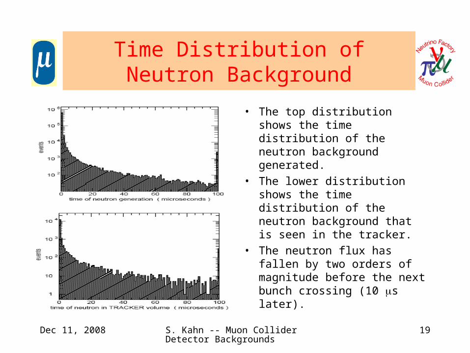
Time Distribution of Neutron Background
• The top distribution shows the time distribution of the neutron background generated.
• The lower distribution shows the time distribution of the neutron background that is seen in the tracker.
• The neutron flux has fallen by two orders of magnitude before the next bunch crossing (10 s later).
Dec 11, 2008 S. Kahn -- Muon Collider Detector Backgrounds
20
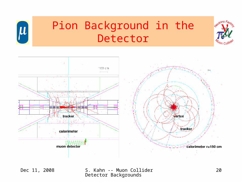
Pion Background in the Detector

Dec 11, 2008 S. Kahn -- Muon Collider Detector Backgrounds
21
Dec 11, 2008 S. Kahn -- Muon Collider Detector Backgrounds
22

Dec 11, 2008 S. Kahn -- Muon Collider Detector Backgrounds
23
Photon and Neutron Fluxes at Radial Planes

Dec 11, 2008 S. Kahn -- Muon Collider Detector Backgrounds
24
Silicon Pad Occupancy as a Function of Radial Position

Dec 11, 2008 S. Kahn -- Muon Collider Detector Backgrounds
25
Dec 11, 2008 S. Kahn -- Muon Collider Detector Backgrounds
26
Bethe-Heitler Muons
• Electrons interacting with the beam pipe wall or tungsten shielding can produce muon pairs. We call these muon pairs Bethe-Heitler Muons.
• These ’s can penetrate the shielding to reach the detector.
• Some Bethe-Heitler ’s will cross the calorimeter and produce catastrophic bremsstrahlung losses that could put spikes in the energy distribution.
• Time-of-Flight information:
– Fast timing can remove B-H ’s in the central calorimeter.
– Significant number of B-H ’s in for forward calorimeter are likely to be in time with the signal.
• Fine Segmentation in both longitudinal and transverse directions will be necessary to distinguish B-H background from signal.
Dec 11, 2008 S. Kahn -- Muon Collider Detector Backgrounds
27
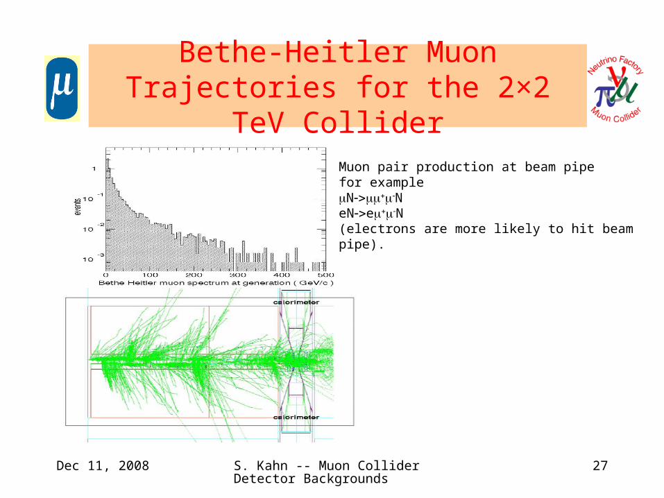
Bethe-Heitler Muon Trajectories for the 2×2 TeV Collider
Muon pair production at beam pipe for exampleNNeNeN (electrons are more likely to hit beam pipe).

Dec 11, 2008 S. Kahn -- Muon Collider Detector Backgrounds
28
Effect of Timing on Bethe-Heitler Muons
Muon pair production at beam pipe for example
NN
50 ps could be attainable now. This is a significant improvement over the last decade

Dec 11, 2008 S. Kahn -- Muon Collider Detector Backgrounds
29
Dec 11, 2008 S. Kahn -- Muon Collider Detector Backgrounds
30

Dec 11, 2008 S. Kahn -- Muon Collider Detector Backgrounds
31
Future Tasks: What We Need to Plan to Do
• We need to start to examine beam related backgrounds produced by currently in vogue IP designs.– This is expected to take a fair amount of work.– We would have to optimize the current IP design as previously done to
reduce backgrounds.• Compare to previous designs.
• We need to reexamine the forward/backward shielding.– Can we reduce the 20º blind cone angle by instrumenting the cone to
identify electromagnetic punch-through background so that it can be ignored.
– Can we instrument the core to identify muons. This would help enormously in identifying multi-lepton channels produced by SUSY.
– Can we instrument the low beta forward-backward regions.• Mary Anne will tell us more about that.