Embed Size (px)
Citation preview
16 Esquire Road, Billerica, MA 01862 Phone 978-284-3906 Email: [email protected]
December 18, 2017
Melanie A. Bachman
Executive Director
Connecticut Siting Council
10 Franklin Street
New Britain, CT 06051
Regarding: Notice of Exempt Modification – Swap of 3 Remote Radio Heads
Property Address: 104 Prospect Hill Road, Windsor, CT (the “Property”, AT&T Site #
CT5192)
Applicant: AT&T Mobility (“AT&T”)
Dear Ms. Bachman:
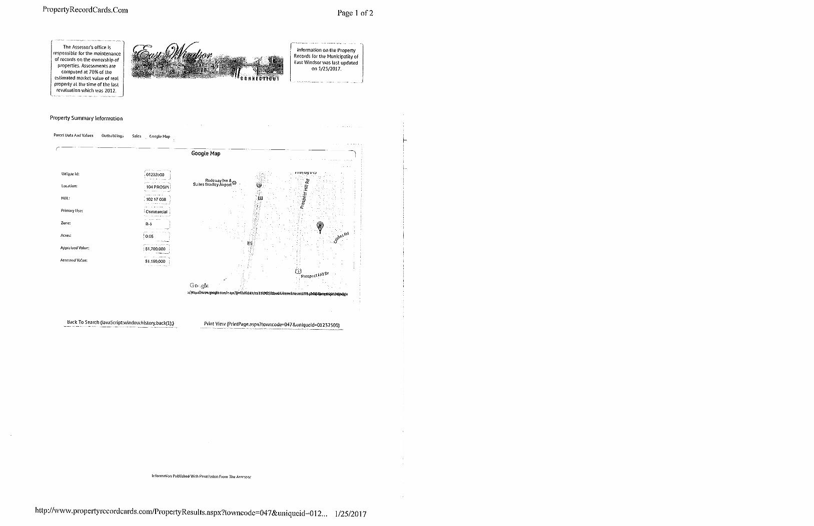
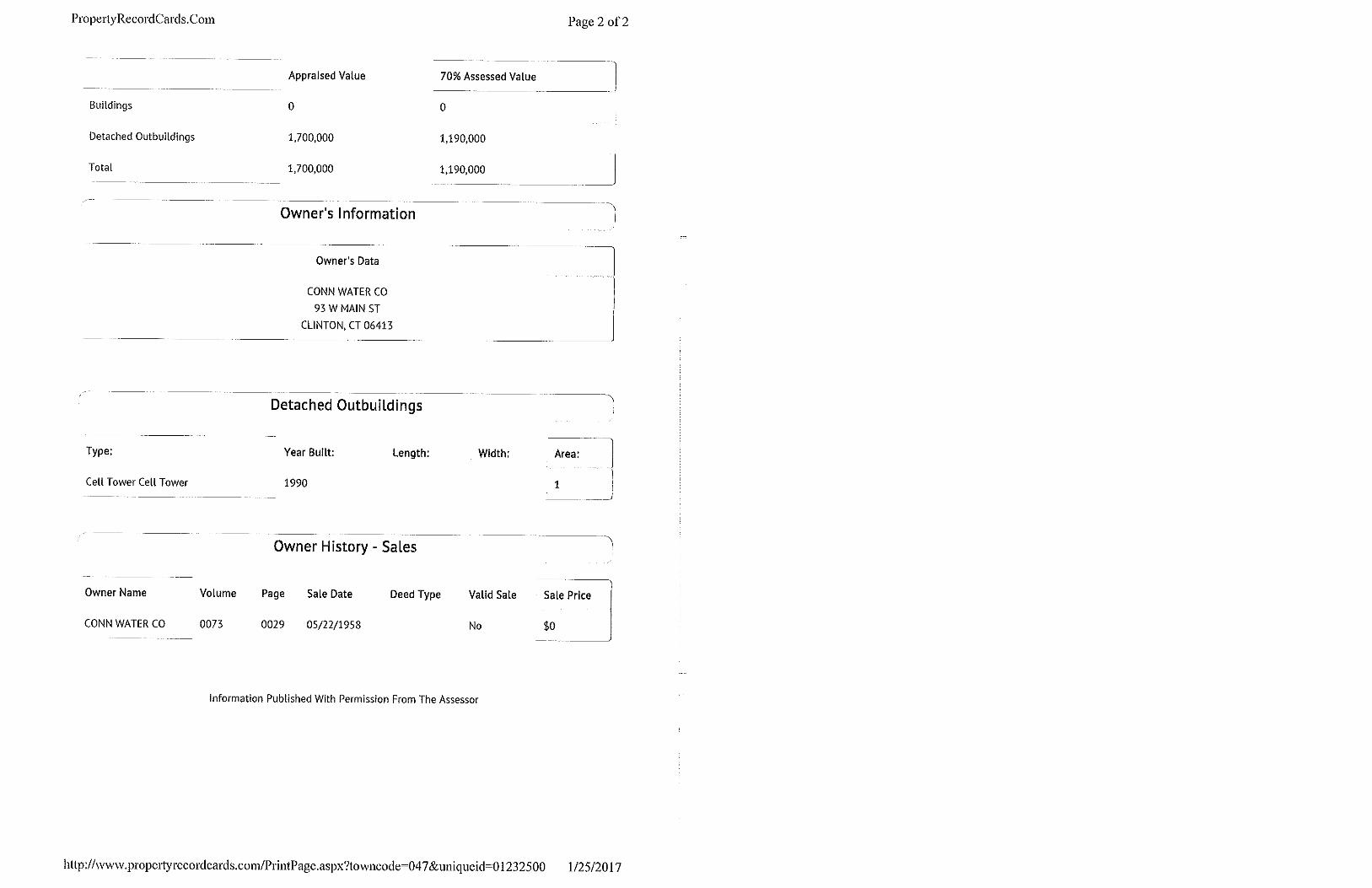
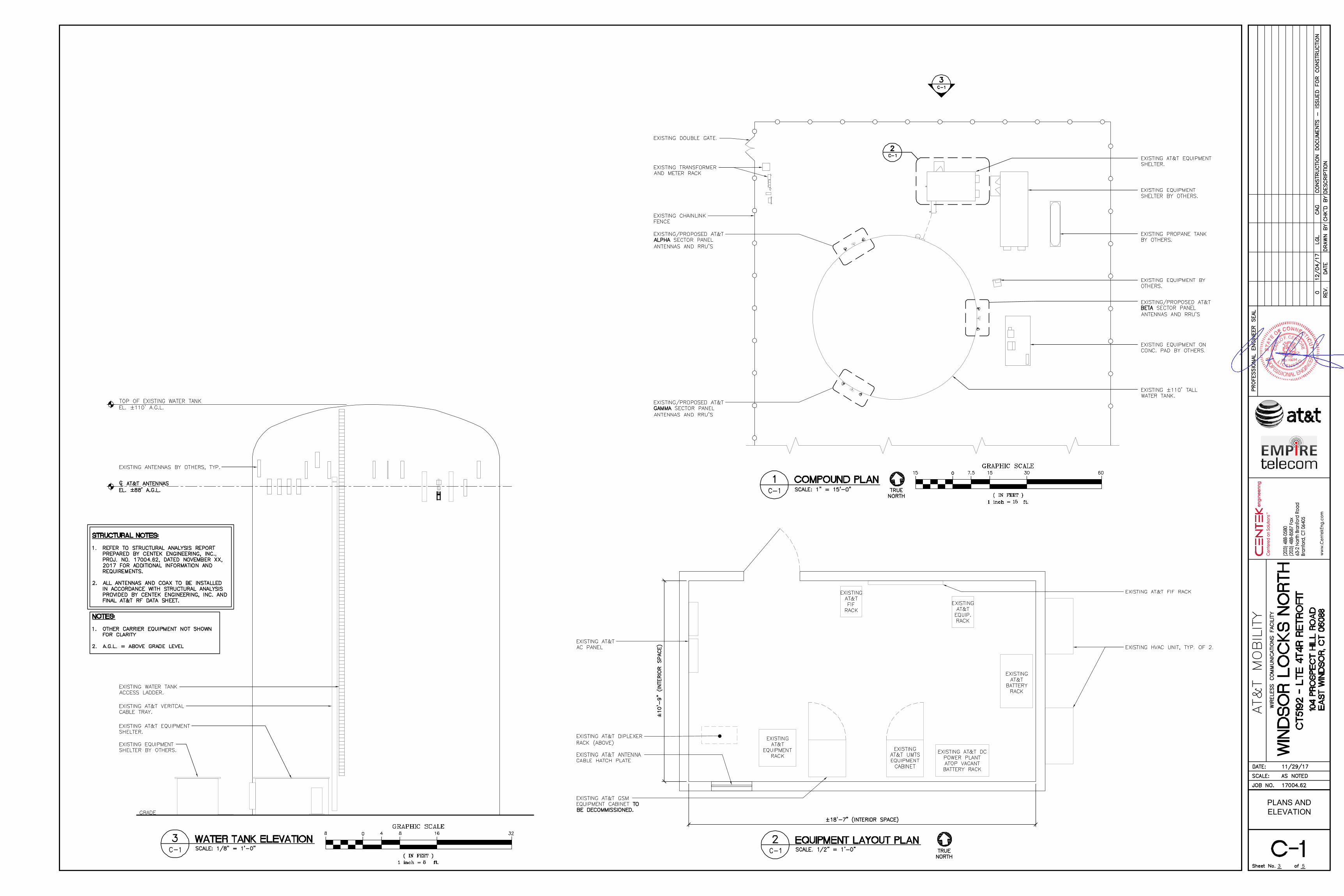
AT&T currently maintains a wireless telecommunications facility on an existing 110 foot, Water
Tank (“tower”) at the above-referenced address, latitude 41.92612778, longitude -72.6046417. AT&T’s
facility consists of six (6) wireless telecommunications antennas at 88 feet. The tower is controlled and
owned by Connecticut Water Company. Assessor’s information is attached hereto.
AT&T desires to modify its existing telecommunications facility by swapping three (3) remote
radios heads for (3) newer remote radio head models. The centerline height of said antennas is and will
remain at 88 feet.
Please accept this application as notification pursuant to R.C.S.A. § 16-50j-73, for construction
that constitutes an exempt modification pursuant to R.C.S.A. § 16-50j-72 (b)(2). In accordance with
R.C.S.A. § 16-50j-73, a copy of this letter is being sent to the First Selectman of the Town of East
Windsor, the Building Inspector of the Town of East Windsor and the Town Planner of the Town of East
Windsor. A copy of this letter is also being sent to Connecticut Water company, the owner of the
structure that AT&T is located.
The planned modifications to AT&T’s facility fall squarely within those activities explicitly
provided for in R.C.S.A. § 16-50j-72(b)(2).
1. The planned modifications will not result in an increase in the height of the existing
structure. AT&T’s antennas and associated lines will be installed at 88 foot level of the 110
foot water tank.
2. The proposed modifications will not involve any changes to ground-mounted equipment
and, therefore will not require an extension of the site boundary.
3. The proposed modification will not increase the noise level at the facility by six decibel or
more, or to levels that exceed state and local criteria.
16 Esquire Road, Billerica, MA 01862 Phone 978-284-3906 Email: [email protected]
4. The operation of the modified facility will not increase radio frequency (RF) emissions at the
facility to a level at or above the Federal Communications Commission (FCC) safety
standard. An RF emissions calculation is attached.
5. The proposed modifications will not cause a change or alteration in the physical or
environmental characteristics of the site.
6. The tower and its foundation can support AT&T’s proposed modifications. (Please see
attached Structural analysis completed by Centek Engineering December 21, 2016).
For the foregoing reasons AT&T respectfully requests that the proposed swap of remote radio
heads be allowed within the exempt modifications under R.C.S.A. § 16-50j-72(b)(2).
Sincerely,
Nicole Caplan
Site Acquisition Specialist
Empire Telecom
CC: The Honorable Robert Maynard, First Selectman, Town of East Windsor
Rand Stanely, Building Inspector, Town of East Windsor
Laurie P. Whitten, CZEO, AICP, Town Planner, Town of East Windsor
Connecticut Water Company, c/o Cindy F. Gaudino


1 5
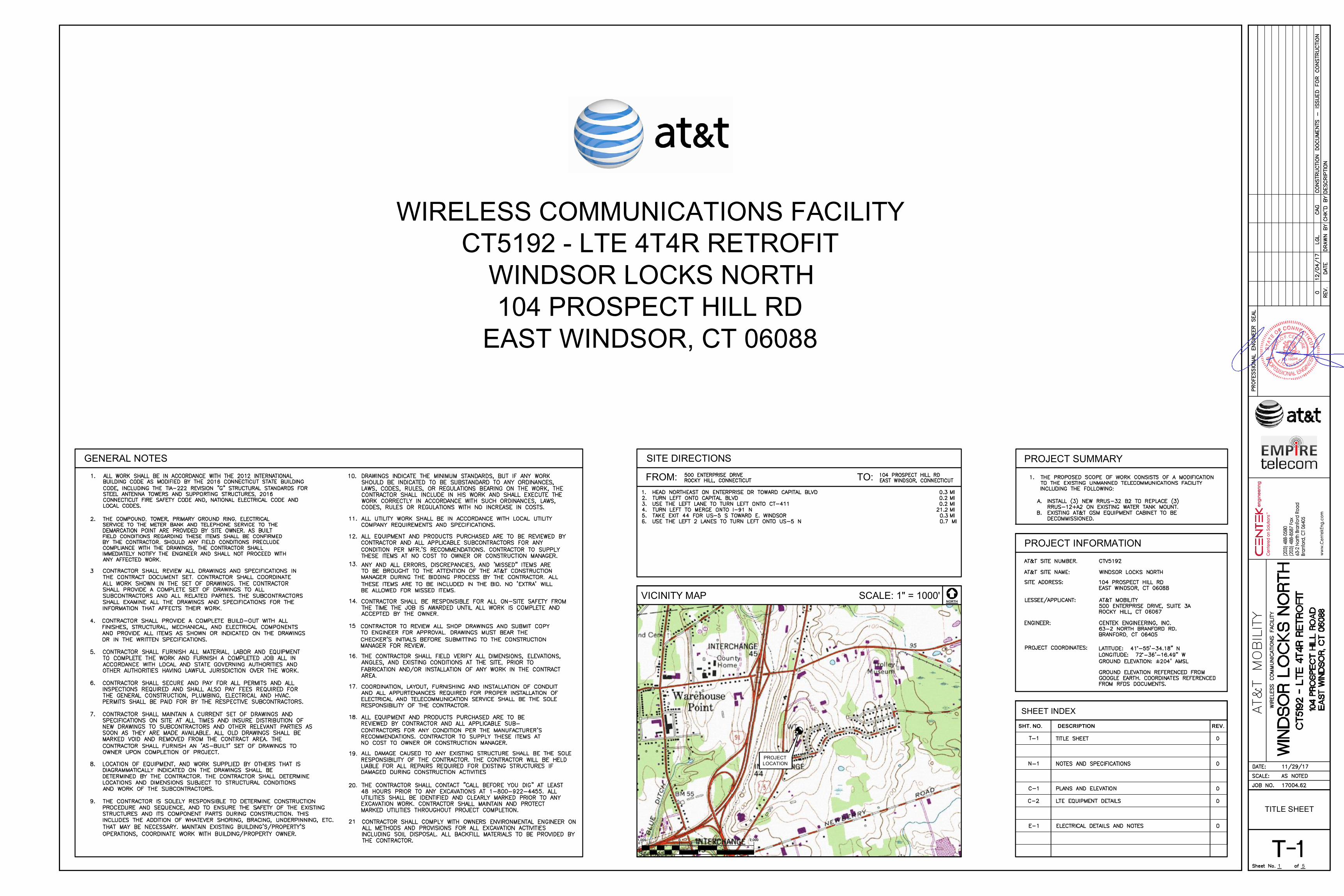
TITLE SHEET
CT5192 - LTE 4T4R RETROFITWINDSOR LOCKS NORTH104 PROSPECT HILL RD
EAST WINDSOR, CT 06088
WIRELESS COMMUNICATIONS FACILITY
PROJECTLOCATION
NORTH
FROM:
SITE DIRECTIONS
TO:
GENERAL NOTES
VICINITY MAP SCALE: 1" = 1000'
PROJECT INFORMATION
REV.DESCRIPTIONSHT. NO.
SHEET INDEX
PROJECT SUMMARY

5
NOTES ANDSPECIFICATIONS
2
5
PLANS ANDELEVATION
3

5
LTEEQUIPMENT
DETAILS
RRU (REMOTE RADIO UNIT)
4
5
ELECTRICALDETAILS AND
NOTES
5
S t r u c t u r a l A n a l y s i s R e p o r t
1 1 0 - f t T a l l E x i s t i n g H o s t W a t e r T a n k
A T & T S i t e # : C T 5 1 9 2
A T & T S i t e N a m e : W i n d s o r L o c k s N o r t h
P r o j e c t : L T E 4 T 4 R R e t r o f i t
P A C E # : M R C T B 0 2 2 1 4 2
P T # : 2 0 5 1 A 0 9 F Y B
F A # : 1 0 0 7 1 3 3 5
1 0 4 P r o s p e c t H i l l R o a dE a s t W i n d s o r , C T 0 6 0 8 8
C e n t e k P r o j e c t N o . 1 7 0 0 4 . 6 2
D a t e : D e c e m b e r 6 , 2 0 1 7
Prepared for:AT&T Mobil ity
500 Enterprise Dr ive, Suite 3ARocky Hil l , CT 06067
CENTEK Engineering, Inc.Structural Analysis - 110-ft Tall Water TankAT&T Site Ref ~ CT5192East Windsor, CTDecember 6, 2017
TABLE OF CONTENTS TOC-1
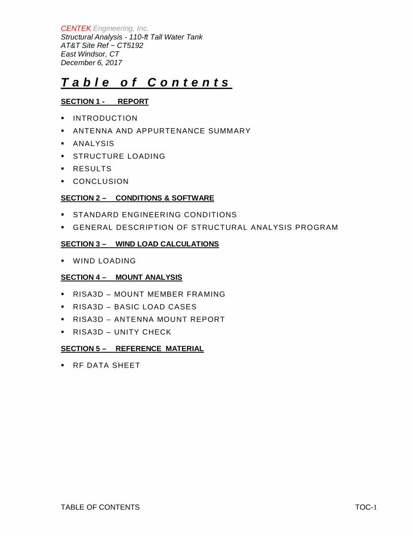
T a b l e o f C o n t e n t sSECTION 1 - REPORT
§ INTRODUCTION§ ANTENNA AND APPURTENANCE SUMMARY§ ANALYSIS§ STRUCTURE LOADING§ RESULTS§ CONCLUSION
SECTION 2 – CONDITIONS & SOFTWARE
§ STANDARD ENGINEERING CONDITIONS§ GENERAL DESCRIPTION OF STRUCTURAL ANALYSIS PROGRAM
SECTION 3 – WIND LOAD CALCULATIONS
§ WIND LOADING
SECTION 4 – MOUNT ANALYSIS
§ RISA3D – MOUNT MEMBER FRAMING§ RISA3D – BASIC LOAD CASES§ RISA3D – ANTENNA MOUNT REPORT§ RISA3D – UNITY CHECK
SECTION 5 – REFERENCE MATERIAL
§ RF DATA SHEET
CENTEK Engineering, Inc.Structural Analysis - 110-ft Tall Water TankAT&T Site Ref ~ CT5192East Windsor, CTDecember 6, 2017
REPORT SECTION 1-1
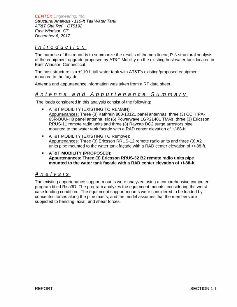
I n t r o d u c t i o nThe purpose of this report is to summarize the results of the non-linear, P-∆ structural analysisof the equipment upgrade proposed by AT&T Mobility on the existing host water tank located inEast Windsor, Connecticut.The host structure is a ±110-ft tall water tank with AT&T’s existing/proposed equipmentmounted to the façade.Antenna and appurtenance information was taken from a RF data sheet.
A n t e n n a a n d A p p u r t e n a n c e S u m m a r y The loads considered in this analysis consist of the following:§ AT&T MOBILITY (EXISTING TO REMAIN):
Appurtenances: Three (3) Kathrein 800-10121 panel antennas, three (3) CCI HPA-65R-BUU-H8 panel antenna, six (6) Powerwave LGP21401 TMAs, three (3) EricssonRRUS-11 remote radio units and three (3) Raycap DC2 surge arrestors pipemounted to the water tank façade with a RAD center elevation of +/-88-ft.
§ AT&T MOBILITY (EXISTING TO Remove):Appurtenances: Three (3) Ericsson RRUS-12 remote radio units and three (3) A2units pipe mounted to the water tank façade with a RAD center elevation of +/-88-ft.
§ AT&T MOBILITY (PROPOSED):Appurtenances: Three (3) Ericsson RRUS-32 B2 remote radio units pipemounted to the water tank façade with a RAD center elevation of +/-88-ft.
A n a l y s i sThe existing appurtenance support mounts were analyzed using a comprehensive computerprogram titled Risa3D. The program analyzes the equipment mounts, considering the worstcase loading condition. The equipment support mounts were considered to be loaded byconcentric forces along the pipe masts, and the model assumes that the members aresubjected to bending, axial, and shear forces.
CENTEK Engineering, Inc.Structural Analysis - 110-ft Tall Water TankAT&T Site Ref ~ CT5192East Windsor, CTDecember 6, 2017
REPORT SECTION 1-2
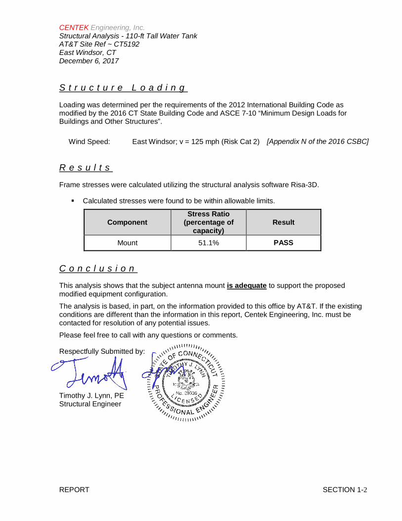
S t r u c t u r e L o a d i n g
Loading was determined per the requirements of the 2012 International Building Code asmodified by the 2016 CT State Building Code and ASCE 7-10 “Minimum Design Loads forBuildings and Other Structures”.
Wind Speed: East Windsor; v = 125 mph (Risk Cat 2) [Appendix N of the 2016 CSBC]
R e s u l t s
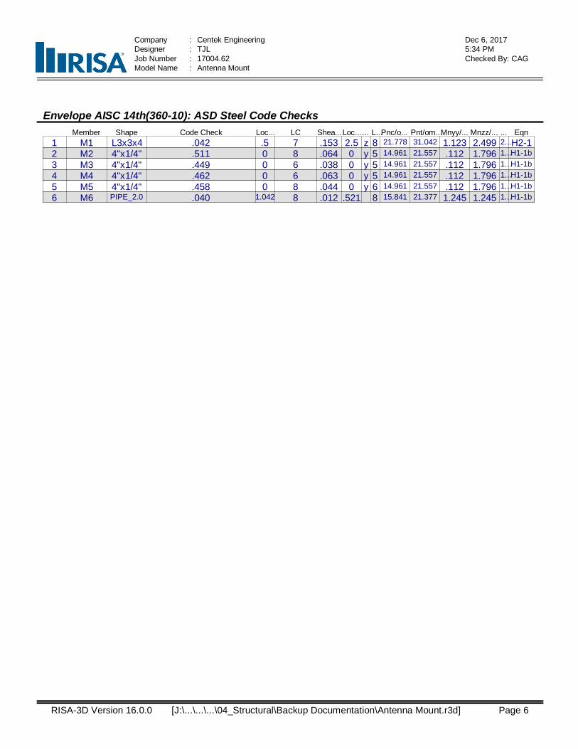
Frame stresses were calculated utilizing the structural analysis software Risa-3D.
§ Calculated stresses were found to be within allowable limits.
ComponentStress Ratio
(percentage ofcapacity)
Result
Mount 51.1% PASS
C o n c l u s i o n
This analysis shows that the subject antenna mount is adequate to support the proposedmodified equipment configuration.The analysis is based, in part, on the information provided to this office by AT&T. If the existingconditions are different than the information in this report, Centek Engineering, Inc. must becontacted for resolution of any potential issues.Please feel free to call with any questions or comments.
Respectfully Submitted by:
Timothy J. Lynn, PEStructural Engineer
CENTEK Engineering, Inc.Structural Analysis - 110-ft Tall Water TankAT&T Site Ref ~ CT5192East Windsor, CTDecember 6, 2017
REPORT SECTION 2-1
S t a n d a r d C o n d i t i o n s f o r F u r n i s h i n g o fP r o f e s s i o n a l E n g i n e e r i n g S e r v i c e s o nE x i s t i n g S t r u c t u r e s
All engineering services are performed on the basis that the information used is current andcorrect. This information may consist of, but is not necessarily limited to:§ Information supplied by the client regarding the structure itself, its foundations, the soil conditions, the antenna and feed line loading on the structure and its components, or other relevant information.§ Information from the field and/or drawings in the possession of Centek Engineering, Inc. or generated by field inspections or measurements of the structure.§ It is the responsibility of the client to ensure that the information provided to Centek Engineering, Inc. and used in the performance of our engineering services is correct and complete. In the absence of information to the contrary, we assume that all structures were constructed in accordance with the drawings and specifications and are in an un- corroded condition and have not deteriorated. It is therefore assumed that its capacity has not significantly changed from the “as new” condition.§ All services will be performed to the codes specified by the client, and we do not imply to meet any other codes or requirements unless explicitly agreed in writing. If wind and ice loads or other relevant parameters are to be different from the minimum values recommended by the codes, the client shall specify the exact requirement. In the absence of information to the contrary, all work will be performed in accordance with the latest revision of ANSI/ASCE10 & ANSI/EIA-222§ All services performed, results obtained, and recommendations made are in accordance with generally accepted engineering principles and practices. Centek Engineering, Inc. is not responsible for the conclusions, opinions and recommendations made by others based on the information we supply.
CENTEK Engineering, Inc.Structural Analysis - 110-ft Tall Water TankAT&T Site Ref ~ CT5192East Windsor, CTDecember 6, 2017
REPORT SECTION 2-2
G E N E R A L D E S C R I P T I O N O F S T R U C T U R A LA N A L Y S I S P R O G R A M ~ R I S A - 3 D
§ RISA-3D Structural Analysis Program is an integrated structural analysis and design softwarepackage for buildings, bridges, tower structures, etc.
Modeling Features:
§ Comprehensive CAD-like graphic drawing/editing capabilities that let you draw, modify andload elements as well as snap, move, rotate, copy, mirror, scale, split, merge, mesh, delete,apply, etc.
§ Versatile drawing grids (orthogonal, radial, skewed)§ Universal snaps and object snaps allow drawing without grids§ Versatile general truss generator§ Powerful graphic select/unselect tools including box, line, polygon, invert, criteria,
spreadsheet selection, with locking§ Saved selections to quickly recall desired selections§ Modification tools that modify single items or entire selections§ Real spreadsheets with cut, paste, fill, math, sort, find, etc.§ Dynamic synchronization between spreadsheets and views so you can edit or view any data
in the plotted views or in the spreadsheets§ Simultaneous view of multiple spreadsheets§ Constant in-stream error checking and data validation§ Unlimited undo/redo capability§ Generation templates for grids, disks, cylinders, cones, arcs, trusses, tanks, hydrostatic
loads, etc.§ Support for all units systems & conversions at any time§ Automatic interaction with RISASection libraries§ Import DXF, RISA-2D, STAAD and ProSteel 3D files§ Export DXF, SDNF and ProSteel 3D files
Analysis Features:
§ Static analysis and P-Delta effects§ Multiple simultaneous dynamic and response spectra analysis using Gupta, CQC or SRSS
mode combinations§ Automatic inclusion of mass offset (5% or user defined) for dynamic analysis§ Physical member modeling that does not require members to be broken up at intermediate
joints§ State of the art 3 or 4 node plate/shell elements§ High-end automatic mesh generation — draw a polygon with any number of sides to create a
mesh of well-formed quadrilateral (NOT triangular) elements.§ Accurate analysis of tapered wide flanges - web, top and bottom flanges may all taper
independently§ Automatic rigid diaphragm modeling§ Area loads with one-way or two-way distributions§ Multiple simultaneous moving loads with standard AASHTO loads and custom moving loads
for bridges, cranes, etc.§ Torsional warping calculations for stiffness, stress and design§ Automatic Top of Member offset modeling§ Member end releases & rigid end offsets§ Joint master-slave assignments§ Joints detachable from diaphragms§ Enforced joint displacements

CENTEK Engineering, Inc.Structural Analysis - 110-ft Tall Water TankAT&T Site Ref ~ CT5192East Windsor, CTDecember 6, 2017
REPORT SECTION 2-3
§ 1-Way members, for tension only bracing, slipping, etc.§ 1-Way springs, for modeling soils and other effects§ Euler members that take compression up to their buckling load, then turn off.§ Stress calculations on any arbitrary shape§ Inactive members, plates, and diaphragms allows you to quickly remove parts of structures
from consideration§ Story drift calculations provide relative drift and ratio to height§ Automatic self-weight calculations for members and plates§ Automatic subgrade soil spring generator
Graphics Features:
§ Unlimited simultaneous model view windows§ Extraordinary “true to scale” rendering, even when drawing§ High-speed redraw algorithm for instant refreshing§ Dynamic scrolling stops right where you want§ Plot & print virtually everything with color coding & labeling§ Rotate, zoom, pan, scroll and snap views§ Saved views to quickly restore frequent or desired views§ Full render or wire-frame animations of deflected model and dynamic mode shapes with
frame and speed control§ Animation of moving loads with speed control§ High quality customizable graphics printing
Design Features:
§ Designs concrete, hot rolled steel, cold formed steel and wood§ ACI 1999/2002, BS 8110-97, CSA A23.3-94, IS456:2000,EC 2-1992 with consistent bar sizes
through adjacent spans§ Exact integration of concrete stress distributions using parabolic or rectangular stress blocks§ Concrete beam detailing (Rectangular, T and L)§ Concrete column interaction diagrams§ Steel Design Codes: AISC ASD 9th, LRFD 2nd & 3rd, HSS Specification, CAN/CSA-S16.1-
1994 & 2004, BS 5950-1-2000, IS 800-1984, Euro 3-1993 including local shape databases§ AISI 1999 cold formed steel design§ NDS 1991/1997/2001 wood design, including Structural Composite Lumber, multi-ply, full
sawn§ Automatic spectra generation for UBC 1997, IBC 2000/2003§ Generation of load combinations: ASCE, UBC, IBC, BOCA, SBC, ACI§ Unbraced lengths for physical members that recognize connecting elements and full lengths
of members§ Automatic approximation of K factors§ Tapered wide flange design with either ASD or LRFD codes§ Optimization of member sizes for all materials and all design codes, controlled by standard or
user-defined lists of available sizes and criteria such as maximum depths§ Automatic calculation of custom shape properties§ Steel Shapes: AISC, HSS, CAN, ARBED, British, Euro, Indian, Chilean§ Light Gage Shapes: AISI, SSMA, Dale / Incor, Dietrich, Marino\WARE§ Wood Shapes: Complete NDS species/grade database§ Full seamless integration with RISAFoot (Ver 2 or better) for advanced footing design and
detailing§ Plate force summation tool

CENTEK Engineering, Inc.Structural Analysis - 110-ft Tall Water TankAT&T Site Ref ~ CT5192East Windsor, CTDecember 6, 2017
REPORT SECTION 2-4
Results Features:
§ Graphic presentation of color-coded results and plotted designs§ Color contours of plate stresses and forces with quadratic smoothing, the contours may also
be animated§ Spreadsheet results with sorting and filtering of: reactions, member & joint deflections, beam
& plate forces/stresses, optimized sizes, code designs, concrete reinforcing, materialtakeoffs, frequencies and mode shapes
§ Standard and user-defined reports§ Graphic member detail reports with force/stress/deflection diagrams and detailed design
calculations and expanded diagrams that display magnitudes at any dialed location§ Saved solutions quickly restore analysis and design results.
Subject:
Location:
Rev. 0: 12/5/17
Wind Load on Equipment per ASCE 7-10
East Windsor, CT
Prepared by: T.J.L; Checked by: C.F.C.Job No. 17004.62
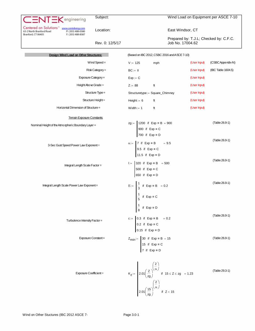
Design Wind Load on Other Structures: (Based on IBC 2012, CSBC 2016 and ASCE 7-10)
Wind Speed = V 125:= mph (User Input) (CSBC Appendix-N)
Risk Category = BC II:= (User Input) (IBC Table 1604.5)
Exposure Category = Exp C:= (User Input)
Height Above Grade = Z 88:= ft (User Input)
Structure Type = Structuretype Square_Chimney:= (User Input)
Structure Height = Height 6:= ft (User Input)
Horizontal Dimension of Structure = Width 1:= ft (User Input)
Terrain Exposure Constants:
zg 1200 Exp B=if
900 Exp C=if
700 Exp D=if
900=:= (Table 26.9-1)Nominal Height of the Atmospheric Boundary Layer =
(Table 26.9-1)α 7 Exp B=if
9.5 Exp C=if
11.5 Exp D=if
9.5=:=3-Sec Gust Speed Power Law Exponent =
(Table 26.9-1)l 320 Exp B=if
500 Exp C=if
650 Exp D=if
500=:=Integral Length Scale Factor =
(Table 26.9-1)Integral Length Scale Power Law Exponent = Ε
13
Exp B=if
15
Exp C=if
18
Exp D=if
0.2=:=
(Table 26.9-1)c 0.3 Exp B=if
0.2 Exp C=if
0.15 Exp D=if
0.2=:=Turbulence Intensity Factor =
Exposure Constant = Zmin 30 Exp B=if
15 Exp C=if
7 Exp D=if
15=:= (Table 26.9-1)
(Table 29.3-1)Exposure Coefficient = Kz 2.01
Zzgæçè
ö÷ø
2αæçèö÷ø
15 Z£ zg£if
2.0115zgæçè
ö÷ø
2αæçèö÷ø
Z 15<if
1.23=:=
Wind on Other Stuctures (IBC 2012 ASCE 7- Page 3.0-1

Subject:
Location:
Rev. 0: 12/5/17
Wind Load on Equipment per ASCE 7-10
East Windsor, CT
Prepared by: T.J.L; Checked by: C.F.C.Job No. 17004.62
Topographic Factor = Kzt 1:= (Eq. 26.8-2)
Wind Directionality Factor = Kd 0.9= (Table 26.6-1)
Velocity Pressure = qz 0.00256 Kz× Kzt× Kd× V2
× 44.35=:= (Eq. 29.3-1)
(Sec 26.9.4)Peak Factor for Background Response = gQ 3.4:=
(Sec 26.9.4)Peak Factor for Wind Response = gv 3.4:=
Equivalent Height of Structure = z Zmin Zmin 0.6 Height×>if
0.6 Height× otherwise
15=:= (Sec 26.9.4)
Intensity of Turbulence = Iz c33z
æçè
ö÷ø
16æçèö÷ø
× 0.228=:= (Eq. 26.9-7)
Integral Length Scale of Turbulence = LZ lz
33æçè
ö÷ø
Ε× 427.057=:= (Eq. 26.9-9)
Background Response Factor = Q1
1 0.63Width Height+
LZ
æçè
ö÷ø
0.63+
0.977=:= (Eq. 26.9-8)
Gust Response Factor = G 0.9251 1.7 gQ× Iz× Q×+( )
1 1.7 gv× Iz×+
éêë
ùúû
× 0.913=:= (Eq. 26.9-6)
Force Coefficient = Cf 1.383= (Fig 29.5-1 - 29.5-3)
Wind Force = F qz G× Cf× 56=:= psf
Wind on Other Stuctures (IBC 2012 ASCE 7- Page 3.0-2
Subject:
Location:
Rev. 0: 12/5/17
Wind Load on Equipment per ASCE 7-10
East Windsor, CT
Prepared by: T.J.L; Checked by: C.F.C.Job No. 17004.62
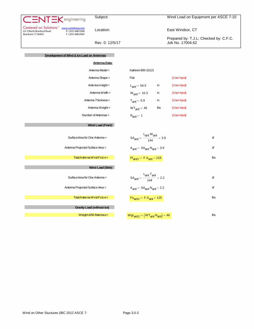
Development of Wind & Ice Load on Antennas
Antenna Data:
Antenna Model = Kathrein 800-10121
Antenna Shape = Flat (User Input)
Antenna Height = Lant 54.5:= in (User Input)
Antenna Width = Want 10.3:= in (User Input)
Antenna Thickness = Tant 5.9:= in (User Input)
Antenna Weight = WTant 46:= lbs (User Input)
Number of Antennas = Nant 1:= (User Input)
Wind Load (Front)
Surface Area for One Antenna = SAantLant Want×
1443.9=:= sf
Antenna Projected Surface Area = Aant SAant Nant× 3.9=:= sf
Total Antenna Wind Force = Ffant1 F Aant× 218=:= lbs
Wind Load (Side)
Surface Area for One Antenna = SAantLant Tant×
1442.2=:= sf
Antenna Projected Surface Area = Aant SAant Nant× 2.2=:= sf
Total Antenna Wind Force = Fsant1 F Aant× 125=:= lbs
Gravity Load (without ice)
Weight of All Antennas = Wgtant1 WTant Nant×( ) 46=:= lbs
Wind on Other Stuctures (IBC 2012 ASCE 7- Page 3.0-3
Subject:
Location:
Rev. 0: 12/5/17
Wind Load on Equipment per ASCE 7-10
East Windsor, CT
Prepared by: T.J.L; Checked by: C.F.C.Job No. 17004.62
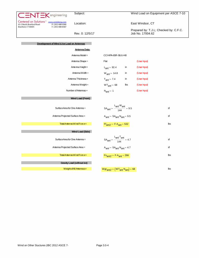
Development of Wind & Ice Load on Antennas
Antenna Data:
Antenna Model = CCI HPA-65R-BUU-H8
Antenna Shape = Flat (User Input)
Antenna Height = Lant 92.4:= in (User Input)
Antenna Width = Want 14.8:= in (User Input)
Antenna Thickness = Tant 7.4:= in (User Input)
Antenna Weight = WTant 68:= lbs (User Input)
Number of Antennas = Nant 1:= (User Input)
Wind Load (Front)
Surface Area for One Antenna = SAantLant Want×
1449.5=:= sf
Antenna Projected Surface Area = Aant SAant Nant× 9.5=:= sf
Total Antenna Wind Force = Ffant2 F Aant× 532=:= lbs
Wind Load (Side)
Surface Area for One Antenna = SAantLant Tant×
1444.7=:= sf
Antenna Projected Surface Area = Aant SAant Nant× 4.7=:= sf
Total Antenna Wind Force = Fsant2 F Aant× 266=:= lbs
Gravity Load (without ice)
Weight of All Antennas = Wgtant2 WTant Nant×( ) 68=:= lbs
Wind on Other Stuctures (IBC 2012 ASCE 7- Page 3.0-4
Subject:
Location:
Rev. 0: 12/5/17
Wind Load on Equipment per ASCE 7-10
East Windsor, CT
Prepared by: T.J.L; Checked by: C.F.C.Job No. 17004.62
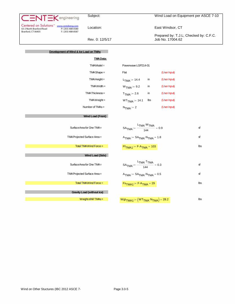
Development of Wind & Ice Load on TMAs
TMA Data:
TMA Model = Powerwave LGP214-01
TMA Shape = Flat (User Input)
TMA Height = LTMA 14.4:= in (User Input)
TMA Width = WTMA 9.2:= in (User Input)
TMA Thickness = TTMA 2.6:= in (User Input)
TMA Weight = WTTMA 14.1:= lbs (User Input)
Number of TMAs = NTMA 2:= (User Input)
Wind Load (Front)
Surface Area for One TMA = SATMALTMA WTMA×
1440.9=:= sf
TMA Projected Surface Area = ATMA SATMA NTMA× 1.8=:= sf
Total TMA Wind Force = FfTMA1 F ATMA× 103=:= lbs
Wind Load (Side)
Surface Area for One TMA = SATMALTMA TTMA×
1440.3=:= sf
TMA Projected Surface Area = ATMA SATMA NTMA× 0.5=:= sf
Total TMA Wind Force = FsTMA1 F ATMA× 29=:= lbs
Gravity Load (without ice)
Weight of All TMAs = WgtTMA1 WTTMA NTMA×( ) 28.2=:= lbs
Wind on Other Stuctures (IBC 2012 ASCE 7- Page 3.0-5
Subject:
Location:
Rev. 0: 12/5/17
Wind Load on Equipment per ASCE 7-10
East Windsor, CT
Prepared by: T.J.L; Checked by: C.F.C.Job No. 17004.62
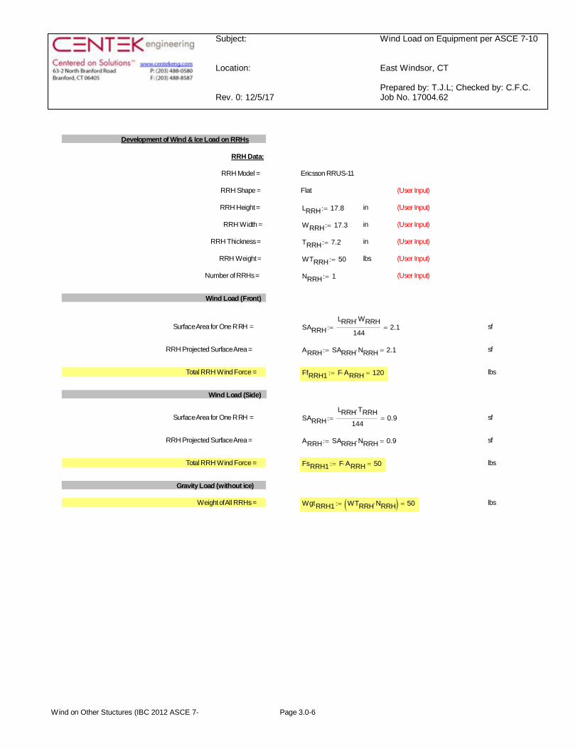
Development of Wind & Ice Load on RRHs
RRH Data:
RRH Model = Ericsson RRUS-11
RRH Shape = Flat (User Input)
RRH Height = LRRH 17.8:= in (User Input)
RRH Width = WRRH 17.3:= in (User Input)
RRH Thickness = TRRH 7.2:= in (User Input)
RRH Weight = WTRRH 50:= lbs (User Input)
Number of RRHs = NRRH 1:= (User Input)
Wind Load (Front)
Surface Area for One RRH = SARRHLRRH WRRH×
1442.1=:= sf
RRH Projected Surface Area = ARRH SARRH NRRH× 2.1=:= sf
Total RRH Wind Force = FfRRH1 F ARRH× 120=:= lbs
Wind Load (Side)
Surface Area for One RRH = SARRHLRRH TRRH×
1440.9=:= sf
RRH Projected Surface Area = ARRH SARRH NRRH× 0.9=:= sf
Total RRH Wind Force = FsRRH1 F ARRH× 50=:= lbs
Gravity Load (without ice)
Weight of All RRHs = WgtRRH1 WTRRH NRRH×( ) 50=:= lbs
Wind on Other Stuctures (IBC 2012 ASCE 7- Page 3.0-6
Subject:
Location:
Rev. 0: 12/5/17
Wind Load on Equipment per ASCE 7-10
East Windsor, CT
Prepared by: T.J.L; Checked by: C.F.C.Job No. 17004.62
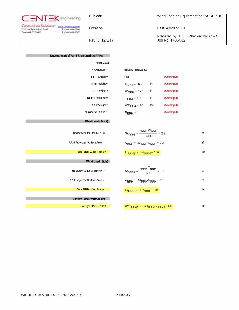
Development of Wind & Ice Load on RRHs
RRH Data:
RRH Model = Ericsson RRUS-32
RRH Shape = Flat (User Input)
RRH Height = LRRH 26.7:= in (User Input)
RRH Width = WRRH 12.1:= in (User Input)
RRH Thickness = TRRH 6.7:= in (User Input)
RRH Weight = WTRRH 60:= lbs (User Input)
Number of RRHs = NRRH 1:= (User Input)
Wind Load (Front)
Surface Area for One RRH = SARRHLRRH WRRH×
1442.2=:= sf
RRH Projected Surface Area = ARRH SARRH NRRH× 2.2=:= sf
Total RRH Wind Force = FfRRH2 F ARRH× 126=:= lbs
Wind Load (Side)
Surface Area for One RRH = SARRHLRRH TRRH×
1441.2=:= sf
RRH Projected Surface Area = ARRH SARRH NRRH× 1.2=:= sf
Total RRH Wind Force = FsRRH2 F ARRH× 70=:= lbs
Gravity Load (without ice)
Weight of All RRHs = WgtRRH2 WTRRH NRRH×( ) 60=:= lbs
Wind on Other Stuctures (IBC 2012 ASCE 7- Page 3.0-7
Subject:
Location:
Rev. 0: 12/5/17
Wind Load on Equipment per ASCE 7-10
East Windsor, CT
Prepared by: T.J.L; Checked by: C.F.C.Job No. 17004.62
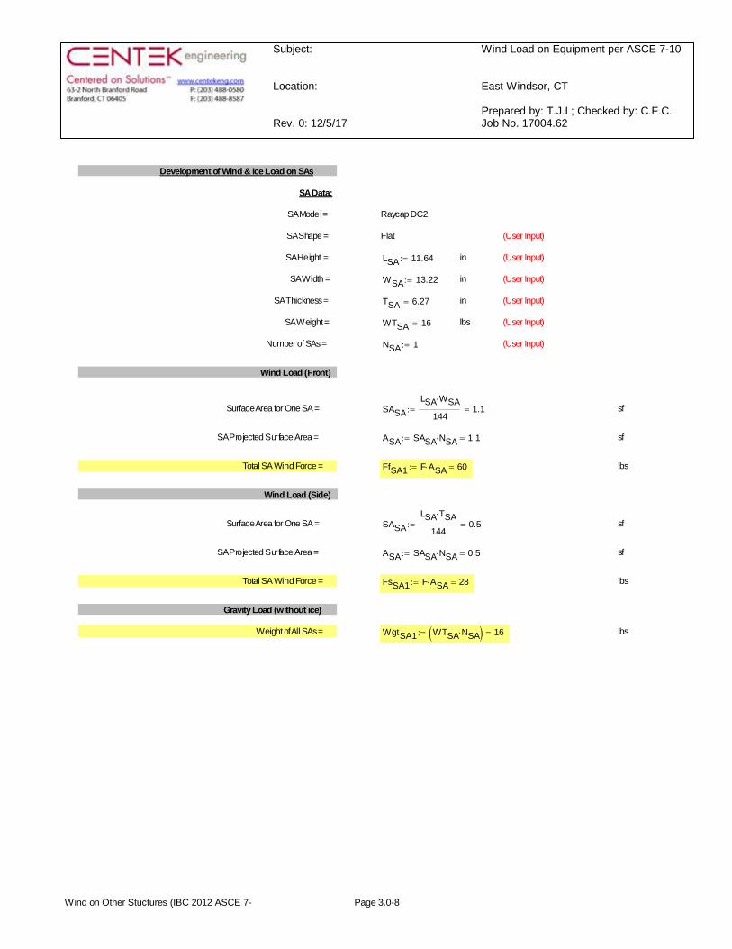
Development of Wind & Ice Load on SAs
SA Data:
SA Model = Raycap DC2
SA Shape = Flat (User Input)
SA Height = LSA 11.64:= in (User Input)
SA Width = WSA 13.22:= in (User Input)
SA Thickness = TSA 6.27:= in (User Input)
SA Weight = WTSA 16:= lbs (User Input)
Number of SAs = NSA 1:= (User Input)
Wind Load (Front)
Surface Area for One SA = SASALSA WSA×
1441.1=:= sf
SA Projected Surface Area = ASA SASA NSA× 1.1=:= sf
Total SA Wind Force = FfSA1 F ASA× 60=:= lbs
Wind Load (Side)
Surface Area for One SA = SASALSA TSA×
1440.5=:= sf
SA Projected Surface Area = ASA SASA NSA× 0.5=:= sf
Total SA Wind Force = FsSA1 F ASA× 28=:= lbs
Gravity Load (without ice)
Weight of All SAs = WgtSA1 WTSA NSA×( ) 16=:= lbs
Wind on Other Stuctures (IBC 2012 ASCE 7- Page 3.0-8
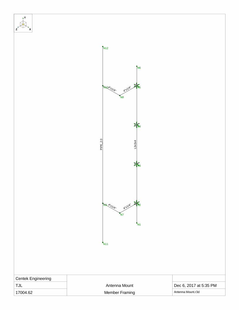
Centek EngineeringTJL
17004.62
Antenna Mount
Member Framing
Dec 6, 2017 at 5:35 PMAntenna Mount.r3d
N1
N2
N3
N4
N5
N6
N7
N8
N9
N10
N11
N12
L3x3
x4
4"x1/4"4"x1/4"
4"x1/4"4"x1/4"
PIPE
_2.0
Y
XZ
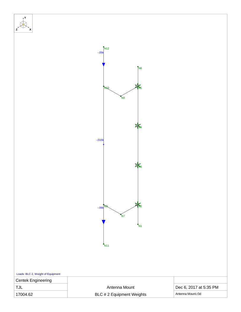
Centek EngineeringTJL
17004.62
Antenna Mount
BLC # 2 Equipment Weights
Dec 6, 2017 at 5:35 PMAntenna Mount.r3d
N1
N2
N3
N4
N5
N6
N7
N8
N9
N10
N11
N12-.05k
-.06k
-.016k
Y
XZ
Loads: BLC 2, Weight of Equipment

Centek EngineeringTJL
17004.62
Antenna Mount
BLC #3 Wind X-Direction
Dec 6, 2017 at 5:36 PMAntenna Mount.r3d
N1
N2
N3
N4
N5
N6
N7
N8
N9
N10
N11
N12
.05k
.07k
.028k
Y
XZ
Loads: BLC 3, Wind X-Direction

Centek EngineeringTJL
17004.62
Antenna Mount
BLC #4 Wind Z-Direction
Dec 6, 2017 at 5:36 PMAntenna Mount.r3d
N1
N2
N3
N4
N5
N6
N7
N8
N9
N10
N11
N12
.12k
.126k
.06k
Y
XZ
Loads: BLC 4, Wind Z-Direction
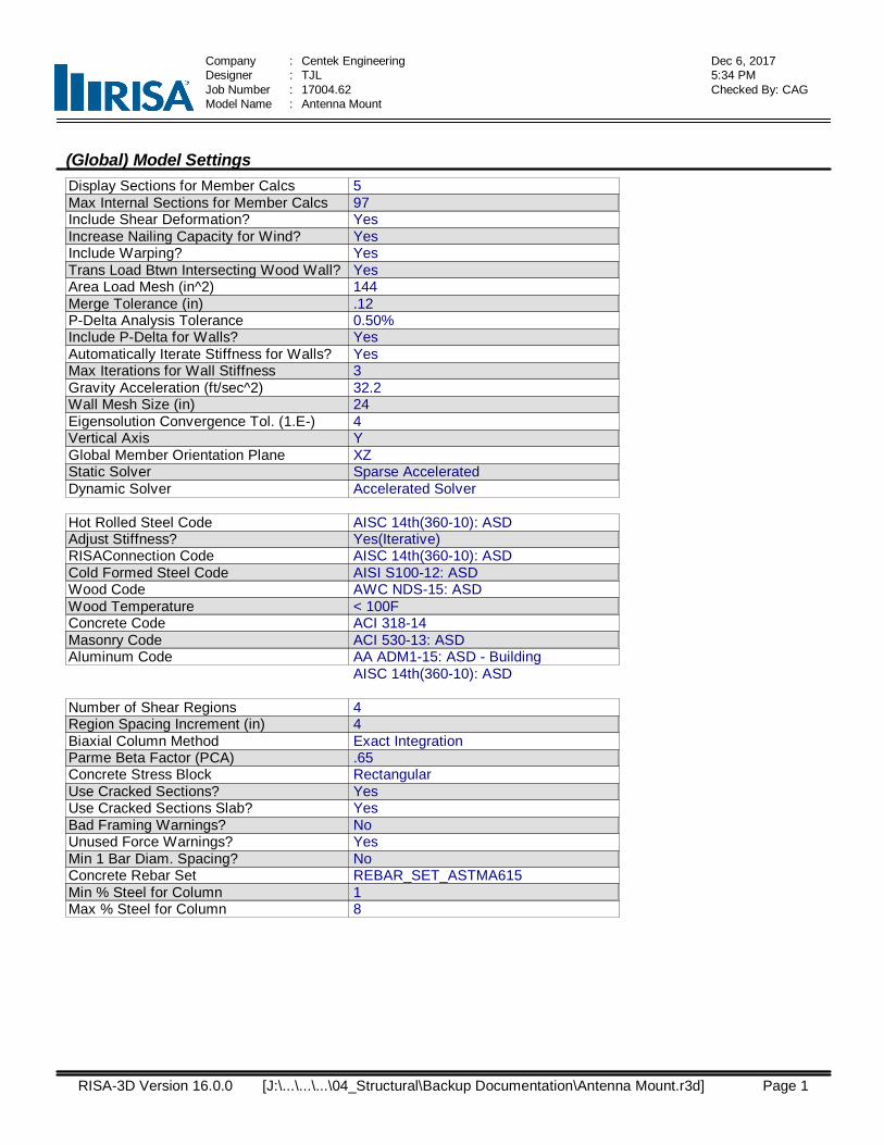
Company : Centek Engineering Dec 6, 20175:34 PMDesigner : TJL
Job Number : 17004.62 Checked By: CAGModel Name : Antenna Mount
(Global) Model SettingsDisplay Sections for Member CalcsMax Internal Sections for Member CalcsInclude Shear Deformation?Increase Nailing Capacity for Wind?Include Warping?Trans Load Btwn Intersecting Wood Wall?Area Load Mesh (in^2)Merge Tolerance (in)P-Delta Analysis ToleranceInclude P-Delta for Walls?Automatically Iterate Stiffness for Walls?Max Iterations for Wall StiffnessGravity Acceleration (ft/sec^2)Wall Mesh Size (in)Eigensolution Convergence Tol. (1.E-)Vertical AxisGlobal Member Orientation PlaneStatic SolverDynamic Solver
597YesYesYesYes144.120.50%YesYes332.2244YXZSparse AcceleratedAccelerated Solver
Hot Rolled Steel CodeAdjust Stiffness?RISAConnection CodeCold Formed Steel CodeWood CodeWood TemperatureConcrete CodeMasonry CodeAluminum Code
AISC 14th(360-10): ASDYes(Iterative)AISC 14th(360-10): ASDAISI S100-12: ASDAWC NDS-15: ASD< 100FACI 318-14ACI 530-13: ASDAA ADM1-15: ASD - BuildingAISC 14th(360-10): ASD
Number of Shear RegionsRegion Spacing Increment (in)Biaxial Column MethodParme Beta Factor (PCA)Concrete Stress BlockUse Cracked Sections?Use Cracked Sections Slab?Bad Framing Warnings?Unused Force Warnings?Min 1 Bar Diam. Spacing?Concrete Rebar SetMin % Steel for ColumnMax % Steel for Column
44Exact Integration.65RectangularYesYesNoYesNoREBAR_SET_ASTMA61518
RISA-3D Version 16.0.0 Page 1 [J:\...\...\...\04_Structural\Backup Documentation\Antenna Mount.r3d]

Company : Centek Engineering Dec 6, 20175:34 PMDesigner : TJL
Job Number : 17004.62 Checked By: CAGModel Name : Antenna Mount
(Global) Model Settings, ContinuedSeismic CodeSeismic Base Elevation (ft)Add Base Weight?Ct XCt ZT X (sec)T Z (sec)R XR ZCt Exp. XCt Exp. ZSD1SDSS1TL (sec)Risk CatDrift Cat
ASCE 7-10Not EnteredYes.02.02Not EnteredNot Entered33.75.751115I or IIOther
Om ZOm XCd ZCd XRho ZRho X
114411
Footing Overturning Safety FactorOptimize for OTM/SlidingCheck Concrete BearingFooting Concrete Weight (k/ft^3)Footing Concrete f'c (ksi)Footing Concrete Ec (ksi)LambdaFooting Steel fy (ksi)Minimum SteelMaximum SteelFooting Top BarFooting Top Bar Cover (in)Footing Bottom BarFooting Bottom Bar Cover (in)Pedestal BarPedestal Bar Cover (in)Pedestal Ties
1NoNo.145436441600.00180.0075#61.5#63#61.5#4
Hot Rolled Steel PropertiesLabel E [ksi] G [ksi] Nu Therm (\1... Density[k/ft^3] Yield[ksi] Ry Fu[ksi] Rt
1 A992 29000 11154 .3 .65 .49 50 1.1 65 1.12 A36 Gr.36 29000 11154 .3 .65 .49 36 1.5 58 1.23 A572 Gr.50 29000 11154 .3 .65 .49 50 1.1 65 1.14 A500 Gr.B RND 29000 11154 .3 .65 .527 42 1.4 58 1.35 A500 Gr.B Rect 29000 11154 .3 .65 .527 46 1.4 58 1.36 A53 Gr.B 29000 11154 .3 .65 .49 35 1.6 60 1.27 A1085 29000 11154 .3 .65 .49 50 1.4 65 1.3
RISA-3D Version 16.0.0 Page 2 [J:\...\...\...\04_Structural\Backup Documentation\Antenna Mount.r3d]
Company : Centek Engineering Dec 6, 20175:34 PMDesigner : TJL
Job Number : 17004.62 Checked By: CAGModel Name : Antenna Mount
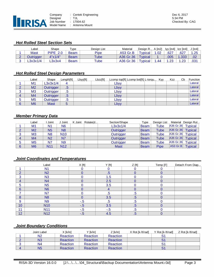
Hot Rolled Steel Section SetsLabel Shape Type Design List Material Design R... A [in2] Iyy [in4] Izz [in4] J [in4]
1 Mast PIPE_2.0 Beam Pipe A53 Gr.B Typical 1.02 .627 .627 1.252 Outrigger 4"x1/4" Beam Tube A36 Gr.36 Typical 1 .005 1.333 .023 L3x3x1/4 L3x3x4 Beam Tube A36 Gr.36 Typical 1.44 1.23 1.23 .031
Hot Rolled Steel Design ParametersLabel Shape Length[ft] Lbyy[ft] Lbzz[ft] Lcomp top[ft] Lcomp bot[ft] L-torqu... Kyy Kzz Cb Function
1 M1 L3x3x1/4 4 Lbyy Lateral2 M2 Outrigger .5 Lbyy Lateral3 M3 Outrigger .5 Lbyy Lateral4 M4 Outrigger .5 Lbyy Lateral5 M5 Outrigger .5 Lbyy Lateral6 M6 Mast 5 Lbyy Lateral
Member Primary DataLabel I Joint J Joint K Joint Rotate(d... Section/Shape Type Design List Material Design Rul...
1 M1 N1 N6 L3x3x1/4 Beam Tube A36 Gr.36 Typical2 M2 N5 N8 Outrigger Beam Tube A36 Gr.36 Typical3 M3 N8 N10 Outrigger Beam Tube A36 Gr.36 Typical4 M4 N2 N7 Outrigger Beam Tube A36 Gr.36 Typical5 M5 N7 N9 Outrigger Beam Tube A36 Gr.36 Typical6 M6 N11 N12 Mast Beam Pipe A53 Gr.B Typical
Joint Coordinates and TemperaturesLabel X [ft] Y [ft] Z [ft] Temp [F] Detach From Diap...
1 N1 0 0 0 02 N2 0 .5 0 03 N3 0 1.5 0 04 N4 0 2.5 0 05 N5 0 3.5 0 06 N6 0 4 0 07 N7 0 .5 .5 08 N8 0 3.5 .5 09 N9 -.5 .5 .5 010 N10 -.5 3.5 .5 011 N11 -.5 -.5 .5 012 N12 -.5 4.5 .5 0
Joint Boundary ConditionsJoint Label X [k/in] Y [k/in] Z [k/in] X Rot.[k-ft/rad] Y Rot.[k-ft/rad] Z Rot.[k-ft/rad]
1 N2 Reaction Reaction Reaction S12 N3 Reaction Reaction Reaction S13 N4 Reaction Reaction Reaction S14 N5 Reaction Reaction Reaction S1
RISA-3D Version 16.0.0 Page 3 [J:\...\...\...\04_Structural\Backup Documentation\Antenna Mount.r3d]
Company : Centek Engineering Dec 6, 20175:34 PMDesigner : TJL
Job Number : 17004.62 Checked By: CAGModel Name : Antenna Mount
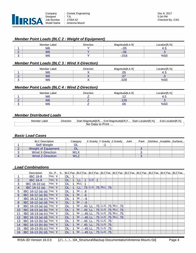
Member Point Loads (BLC 2 : Weight of Equipment)Member Label Direction Magnitude[k,k-ft] Location[ft,%]
1 M6 Y -.05 4.52 M6 Y -.06 .53 M6 Y -.016 %50
Member Point Loads (BLC 3 : Wind X-Direction)Member Label Direction Magnitude[k,k-ft] Location[ft,%]
1 M6 X .05 4.52 M6 X .07 .53 M6 X .028 %50
Member Point Loads (BLC 4 : Wind Z-Direction)Member Label Direction Magnitude[k,k-ft] Location[ft,%]
1 M6 Z .12 4.52 M6 Z .126 .53 M6 Z .06 %50
Member Distributed LoadsMember Label Direction Start Magnitude[k/ft,... End Magnitude[k/ft,F... Start Location[ft,%] End Location[ft,%]
No Data to Print ...
Basic Load CasesBLC Description Category X Gravity Y Gravity Z Gravity Joint Point Distribut...Area(Me...Surface(...
1 Self Weight DL -12 Weight of Equipment DL 33 Wind X-Direction WLX 34 Wind Z-Direction WLZ 3
Load CombinationsDescription So...P... S... BLC Fac...BLC Fac...BLC Fac...BLC Fac...BLC Fac...BLC Fac...BLC Fac...BLC Fac...BLC Fac...BLC Fac...
1 IBC 16-8 Yes Y DL 12 IBC 16-9 Yes Y DL 1 LL 1 LLS 13 IBC 16-10 (a) Yes Y DL 1 RLL 14 IBC 16-11 (a) Yes Y DL 1 LL .75 LLS .75 RLL .755 IBC 16-12 (a) (a) Yes Y DL 1 W... .66 IBC 16-12 (a) (b) Yes Y DL 1 W... .67 IBC 16-12 (a) (c) Yes Y DL 1 W... -.68 IBC 16-12 (a) (d) Yes Y DL 1 W... -.69 IBC 16-13 (a) (a) Yes Y DL 1 W... .45 LL .75 LLS .75 RLL .7510 IBC 16-13 (a) (b) Yes Y DL 1 W... .45 LL .75 LLS .75 RLL .7511 IBC 16-13 (a) (c) Yes Y DL 1 W... -.45 LL .75 LLS .75 RLL .7512 IBC 16-13 (a) (d) Yes Y DL 1 W... -.45 LL .75 LLS .75 RLL .7513 IBC 16-13 (b) (a) Yes Y DL 1 W... .45 LL .75 LLS .7514 IBC 16-13 (b) (b) Yes Y DL 1 W... .45 LL .75 LLS .7515 IBC 16-13 (b) (c) Yes Y DL 1 W... -.45 LL .75 LLS .7516 IBC 16-13 (b) (d) Yes Y DL 1 W... -.45 LL .75 LLS .75
RISA-3D Version 16.0.0 Page 4 [J:\...\...\...\04_Structural\Backup Documentation\Antenna Mount.r3d]
Company : Centek Engineering Dec 6, 20175:34 PMDesigner : TJL
Job Number : 17004.62 Checked By: CAGModel Name : Antenna Mount
Load Combinations (Continued)Description So...P... S... BLC Fac...BLC Fac...BLC Fac...BLC Fac...BLC Fac...BLC Fac...BLC Fac...BLC Fac...BLC Fac...BLC Fac...
17 IBC 16-15 (a) Yes Y DL .6 W... .618 IBC 16-15 (b) Yes Y DL .6 W... .619 IBC 16-15 (c) Yes Y DL .6 W... -.620 IBC 16-15 (d) Yes Y DL .6 W... -.6
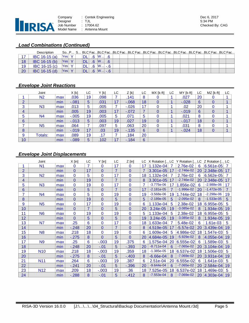
Envelope Joint ReactionsJoint X [k] LC Y [k] LC Z [k] LC MX [k-ft] LC MY [k-ft] LC MZ [k-ft] LC
1 N2 max .036 19 .098 7 .141 8 0 1 .027 20 0 12 min -.081 5 .031 17 -.068 18 0 1 -.028 6 0 13 N3 max .013 5 .005 7 -.026 17 0 1 .02 20 0 14 min .005 19 .003 17 -.072 7 0 1 -.019 6 0 15 N4 max -.005 19 .005 5 .071 5 0 1 .021 8 0 16 min -.013 5 .003 19 .027 19 0 1 -.017 18 0 17 N5 max .064 7 .097 5 .063 20 0 1 .031 8 0 18 min -.019 17 .03 19 -.135 6 0 1 -.024 18 0 19 Totals: max .089 19 .17 7 .184 2010 min -.089 5 .102 17 -.184 6
Envelope Joint DisplacementsJoint X [in] LC Y [in] LC Z [in] LC X Rotation [... LC Y Rotation [... LC Z Rotation [... LC
1 N1 max 0 7 0 17 0 17 1.132e-04 7 2.76e-02 6 6.561e-05 72 min 0 17 0 7 0 7 3.301e-05 17 -2.746e-02 20 2.348e-05 173 N2 max 0 5 0 17 0 18 1.132e-04 7 2.76e-02 6 6.562e-05 74 min 0 19 0 7 0 8 3.301e-05 17 -2.746e-02 20 2.348e-05 175 N3 max 0 19 0 17 0 7 -3.775e-06 17 1.856e-02 6 -2.988e-06 176 min 0 5 0 7 0 17 -2.181e-05 7 -1.996e-02 20 -1.472e-05 77 N4 max 0 5 0 19 0 19 -3.568e-06 19 1.744e-02 18 -2.298e-06 198 min 0 19 0 5 0 5 -2.189e-05 5 -2.095e-02 8 -1.533e-05 59 N5 max 0 17 0 19 0 6 1.133e-04 5 2.38e-02 18 6.955e-05 510 min 0 7 0 5 0 20 3.24e-05 19 -3.085e-02 8 1.934e-05 1911 N6 max 0 19 0 19 0 5 1.133e-04 5 2.38e-02 18 6.955e-05 512 min 0 5 0 5 0 19 3.24e-05 19 -3.085e-02 8 1.934e-05 1913 N7 max .25 6 0 17 0 18 1.633e-04 7 5.48e-02 6 1.61e-03 514 min -.248 20 0 7 0 8 4.519e-05 17 -5.57e-02 20 3.439e-04 1915 N8 max .218 18 0 19 0 6 1.609e-04 5 4.986e-02 18 1.547e-03 516 min -.275 8 0 5 0 20 4.684e-05 19 -5.929e-02 8 4.055e-04 1917 N9 max .25 6 -.003 19 .375 6 1.575e-04 20 6.555e-02 6 1.589e-03 518 min -.248 20 -.01 5 -.393 20 -8.711e-04 6 -7.065e-02 20 3.104e-04 1919 N10 max .218 18 -.003 19 .359 18 -1.385e-05 18 6.537e-02 18 1.506e-03 520 min -.275 8 -.01 5 -.403 8 -6.66e-04 8 -7.069e-02 20 3.931e-04 1921 N11 max .264 6 -.003 19 .387 6 2.51e-04 20 6.555e-02 6 1.641e-03 522 min -.241 20 -.01 5 -.396 20 -9.644e-04 6 -7.065e-02 20 2.584e-04 1923 N12 max .209 18 -.003 19 .36 18 7.525e-05 18 6.537e-02 18 1.469e-03 524 min -.288 8 -.01 5 -.412 8 -7.553e-04 8 -7.069e-02 20 4.303e-04 19
RISA-3D Version 16.0.0 Page 5 [J:\...\...\...\04_Structural\Backup Documentation\Antenna Mount.r3d]
Company : Centek Engineering Dec 6, 20175:34 PMDesigner : TJL
Job Number : 17004.62 Checked By: CAGModel Name : Antenna Mount
Envelope AISC 14th(360-10): ASD Steel Code ChecksMember Shape Code Check Loc... LC Shea...Loc...... L...Pnc/o... Pnt/om...Mnyy/... Mnzz/... ... Eqn
1 M1 L3x3x4 .042 .5 7 .153 2.5 z 8 21.778 31.042 1.123 2.499 2...H2-12 M2 4"x1/4" .511 0 8 .064 0 y 5 14.961 21.557 .112 1.796 1...H1-1b3 M3 4"x1/4" .449 0 6 .038 0 y 5 14.961 21.557 .112 1.796 1...H1-1b4 M4 4"x1/4" .462 0 6 .063 0 y 5 14.961 21.557 .112 1.796 1...H1-1b5 M5 4"x1/4" .458 0 8 .044 0 y 6 14.961 21.557 .112 1.796 1...H1-1b6 M6 PIPE_2.0 .040 1.042 8 .012 .521 8 15.841 21.377 1.245 1.245 1...H1-1b
RISA-3D Version 16.0.0 Page 6 [J:\...\...\...\04_Structural\Backup Documentation\Antenna Mount.r3d]
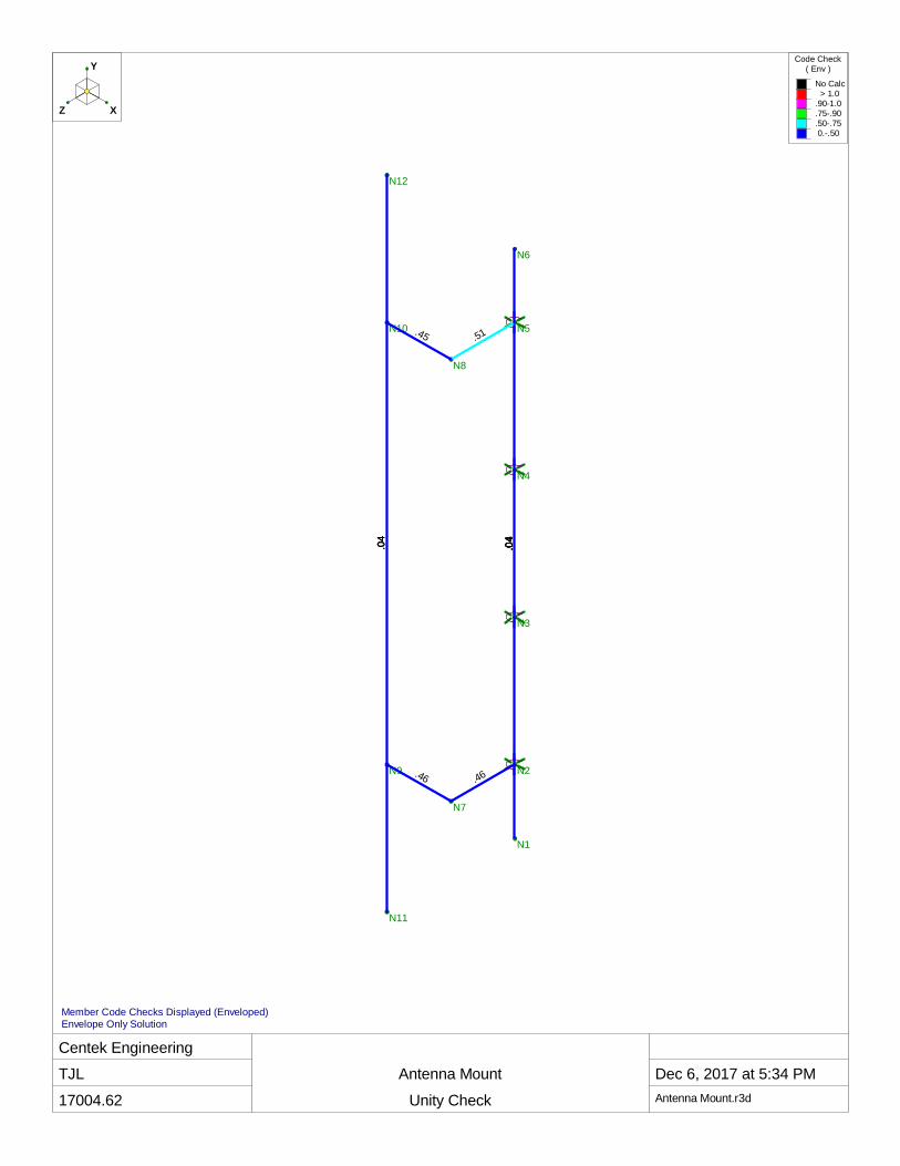
Centek EngineeringTJL
17004.62
Antenna Mount
Unity Check
Dec 6, 2017 at 5:34 PMAntenna Mount.r3d
N1
N2
N3
N4
N5
N6
N7
N8
N9
N10
N11
N12
.04
.04
.46.46
.04
.04
.04
.04
.51
.04
.45
.04
Y
XZ
Code Check( Env )
No Calc > 1.0.90-1.0.75-.90.50-.75 0.-.50
Member Code Checks Displayed (Enveloped)Envelope Only Solution
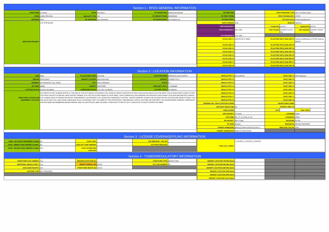
Section 1 - RFDS GENERAL INFORMATIONRFDS NAME: CTV5192 DATE: 03/13/2017 RF DESIGN ENG: Mohammed Rahman
ISSUE: 1xBBU RRH ADD Approved? (Y/N): Yes RF DESIGN PHONE: 8602586350
REVISION: Final RF MANAGER: John Benedetto RF DESIGN EMAIL: [email protected]
INITIATIVE /PROJECT:
LTE 4T4R Retrofit
RF PERF ENG: RFDS PROGRAM TYPE: 2017 LTE Multi Carrier
RF PERF PHONE: RFDS TECHNOLOGY: 4TXRX
RF PERF EMAIL: STATE/STATUS: Preliminary/Approved
RFDS VERSION: 1.00 RFDS ID: 1684113
GSM FREQUENCY: Created By: mr673a Updated By: dc5778
UMTS FREQUENCY: 850, 1900 Date Created: 3/13/2017 6:13:07
PM
Date Updated: 3/23/2017 9:39:29
AM
LTE FREQUENCY: 700, 1900
I-PLAN JOB # 1: NER-RCTB-17-00651 IPLAN PRD GRP || SUB GRP #1: Antenna Modifications || 4TXRX Antenna
Retrofit
I-PLAN JOB # 2: IPLAN PRD GRP || SUB GRP #2:
I-PLAN JOB # 3: IPLAN PRD GRP || SUB GRP #3:
I-PLAN JOB # 4: IPLAN PRD GRP || SUB GRP #4:
I-PLAN JOB # 5: IPLAN PRD GRP || SUB GRP #5:
I-PLAN JOB # 6: IPLAN PRD GRP || SUB GRP #6:
I-PLAN JOB # 7: IPLAN PRD GRP || SUB GRP #7:
I-PLAN JOB # 8: IPLAN PRD GRP || SUB GRP #8:
Section 2 - LOCATION INFORMATIONUSID: 4566 FA LOCATION CODE: 10071335 LOCATION NAME: WINDSOR LOCKS NORTH
REGION: NORTHEAST MARKET CLUSTER: NEW ENGLAND MARKET: CONNECTICUT
ADDRESS: 104 PROSPECT HILL ROAD CITY: EAST WINDSOR STATE: CT
ZIP CODE: 06088 COUNTY: HARTFORD LONG (DEC. DEG.): -72.6046989
LATITUDE (D-M-S): 41d 55m 36.09084s LONGITUDE (D-M-S): -72d -36m -16.91604s LAT (DEC. DEG.): 41.9266919
DIRECTIONS, ACCESS AND
EQUIPMENT LOCATION:
I-91 NORTH TO EXIT 44,BEAR NORTH AT THE END OF THE EXIT,WHICH IS PROSPECT HILL ROAD.GO ABOUT 6/10TNTHS OF MILE,THE ACCESS ROAD IS ON THE RIGHT.THE ACCESS ROAD IS RIGHT AFTER
YOU PASS THE KETTLE BROOK CARE CENTER. DEMARC IS IN THE TELCO BOX INSIDE OF GATE AREA.. GATE COMBO:9110,1452,2500SHELTER;GROUND LEVELCIPHER LOCK;3534 AND MASTER CODEON
LTE ALARMS:7/6/14LTE RADIOS;ON WATER TANKADDRESS: 104 PROSPECT HILL ROAD,EAST WINDSOR,CT.ACCESS : WATER COMPANY ASKING FOR 48 HOUR NOTICE FOR ROUTINE WORK,AT NIGHT YOU
CAN GO IN JUST CALL AND LEAVE A MESSAGE ON AL'S VOICEMAIL THAT YOU WERE AT THE SITECONTACT: 860-669-8630 X 3057;AL-DAYTIME ONLYSECURITY: NO ISSUESPOWER COMPANY: NORTHEAST
UTILITIES (800) 286-2000METER:089-085-359FIRE: (860) 745-1878 POLICE: (860) 763-6400T-1:GSM:HCGS-737362-ET-107T-1:GSM:HCGS:727136-ET-52UMTS:ON FIBER
ORACLE PTN # 1: 2051A09FYB PACE JOB # 1: MRCTB022142
ORACLE PTN # 2: PACE JOB # 2:
ORACLE PTN # 3: PACE JOB # 3:
ORACLE PTN # 4: PACE JOB # 4:
ORACLE PTN # 5: PACE JOB # 5:
ORACLE PTN # 6: PACE JOB # 6:
ORACLE PTN # 7: PACE JOB # 7:
ORACLE PTN # 8: PACE JOB # 8:
BORDER CELL WITH CONTOUR COORD: SEARCH RING NAME:
AM STUDY REQ'D (Y/N): No SEARCH_RING_ID:
FREQ COORD: BTA: MSA / RSA:
OPS DISTRICT: CT-North LAC(GSM): 05005
OPS ZONE: NE_CT_N_TLDN_N_CS LAC(UMTS): 05993
RF DISTRICT: NPO Triage BSC(GSM): BCT05
RF ZONE: Hotseat RNC(UMTS): MDTWCTNICR0R04
PARENT NAME(GSM): MIDDLETOWN-GSM MTSO-BSC-5 MME POOL ID(LTE): FF01
PARENT NAME(UMTS): MIDDLETOWN RNC04
Section 3 - LICENSE COVERAGE/FILING INFORMATIONCGSA - NO FILING TRIGGERED (Yes/No): No CGSA LOSS: PCS REDUCED - UPS ZIP:
CGSA - MINOR FILING NEEDED (Yes/No):: No CGSA EXT AGMT NEEDED: PCS POPS REDUCED:
CGSA - MAJOR FILING NEEDED (Yes/No): Yes CGSA SCORECARD
UPDATED:
CGSA CALL SIGNS:
z_KNLB312,z_KNLB312,z_KNLB312
Section 4 - TOWER/REGULATORY INFORMATIONSTRUCTURE AT&T OWNED?: Yes GROUND ELEVATION (ft): STRUCTURE TYPE: WATER TANK
ADDITIONAL REGULATORY?: Yes HEIGHT OVERALL (ft): 140.00 FCC ASR NUMBER: NR
SUB-LEASE RIGHTS?: Yes STRUCTURE HEIGHT (ft): 140.00
LIGHTING TYPE: NOT REQUIRED
a
MARKET LOCATION 700 MHz Band:
MARKET LOCATION 850 MHz Band:
MARKET LOCATION 1900 MHz Band:
MARKET LOCATION AWS Band:
MARKET LOCATION WCS Band:
MARKET LOCATION Future Band:
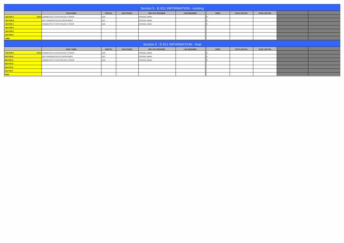
Section 5 - E-911 INFORMATION - existingPSAP NAME: PSAP ID: E911 PHASE: MPC SVC PROVIDER: LMU REQUIRED:
SECTOR A E-911 CONNECTICUT STATE POLICE-H TROOP 1320 INTRADO_MIAMI
SECTOR B EAST WINDSOR POLICE DEPARTMENT 1337 INTRADO_MIAMI
SECTOR C CONNECTICUT STATE POLICE-H TROOP 1320 INTRADO_MIAMI
SECTOR D
SECTOR E
SECTOR F
OMNI
ESRN: DATE LIVE PH1: DATE LIVE PH2:
0
0
0
Section 5 - E-911 INFORMATION - finalPSAP NAME: PSAP ID: E911 PHASE: MPC SVC PROVIDER: LMU REQUIRED:
SECTOR A E-911 CONNECTICUT STATE POLICE-H TROOP 1320 INTRADO_MIAMI
SECTOR B EAST WINDSOR POLICE DEPARTMENT 1337 INTRADO_MIAMI
SECTOR C CONNECTICUT STATE POLICE-H TROOP 1320 INTRADO_MIAMI
SECTOR D
SECTOR E
SECTOR F
OMNI
ESRN: DATE LIVE PH1: DATE LIVE PH2:
0
0
0
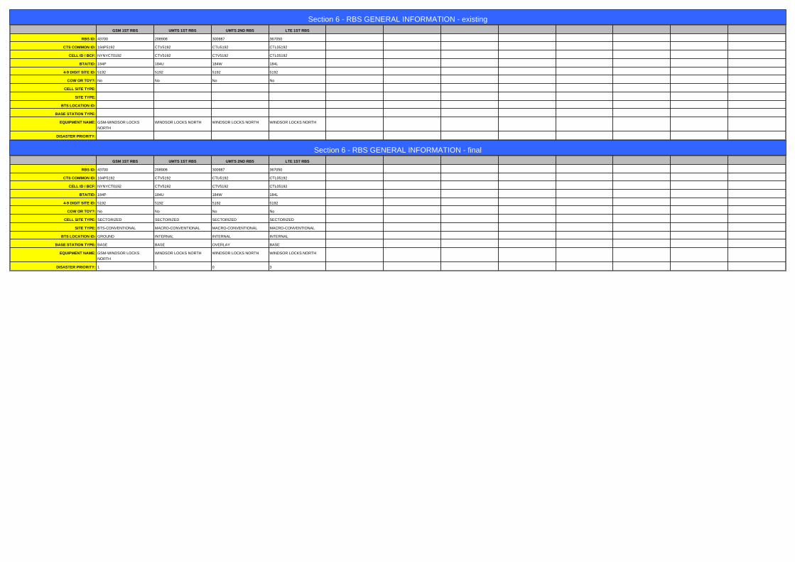
Section 6 - RBS GENERAL INFORMATION - existingGSM 1ST RBS UMTS 1ST RBS UMTS 2ND RBS LTE 1ST RBS
RBS ID: 43700 208908 300987 367050
CTS COMMON ID: 184P5192 CTV5192 CTU5192 CTL05192
CELL ID / BCF: NYNYCT0192 CTV5192 CTV5192 CTL05192
BTA/TID: 184P 184U 184W 184L
4-9 DIGIT SITE ID: 5192 5192 5192 5192
COW OR TOY?: No No No No
CELL SITE TYPE:
SITE TYPE:
BTS LOCATION ID:
BASE STATION TYPE:
EQUIPMENT NAME: GSM-WINDSOR LOCKS
NORTH
WINDSOR LOCKS NORTH WINDSOR LOCKS NORTH WINDSOR LOCKS NORTH
DISASTER PRIORITY:
Section 6 - RBS GENERAL INFORMATION - finalGSM 1ST RBS UMTS 1ST RBS UMTS 2ND RBS LTE 1ST RBS
RBS ID: 43700 208908 300987 367050
CTS COMMON ID: 184P5192 CTV5192 CTU5192 CTL05192
CELL ID / BCF: NYNYCT0192 CTV5192 CTV5192 CTL05192
BTA/TID: 184P 184U 184W 184L
4-9 DIGIT SITE ID: 5192 5192 5192 5192
COW OR TOY?: No No No No
CELL SITE TYPE: SECTORIZED SECTORIZED SECTORIZED SECTORIZED
SITE TYPE: BTS-CONVENTIONAL MACRO-CONVENTIONAL MACRO-CONVENTIONAL MACRO-CONVENTIONAL
BTS LOCATION ID: GROUND INTERNAL INTERNAL INTERNAL
BASE STATION TYPE: BASE BASE OVERLAY BASE
EQUIPMENT NAME: GSM-WINDSOR LOCKS
NORTH
WINDSOR LOCKS NORTH WINDSOR LOCKS NORTH WINDSOR LOCKS NORTH
DISASTER PRIORITY: 1 1 0 3
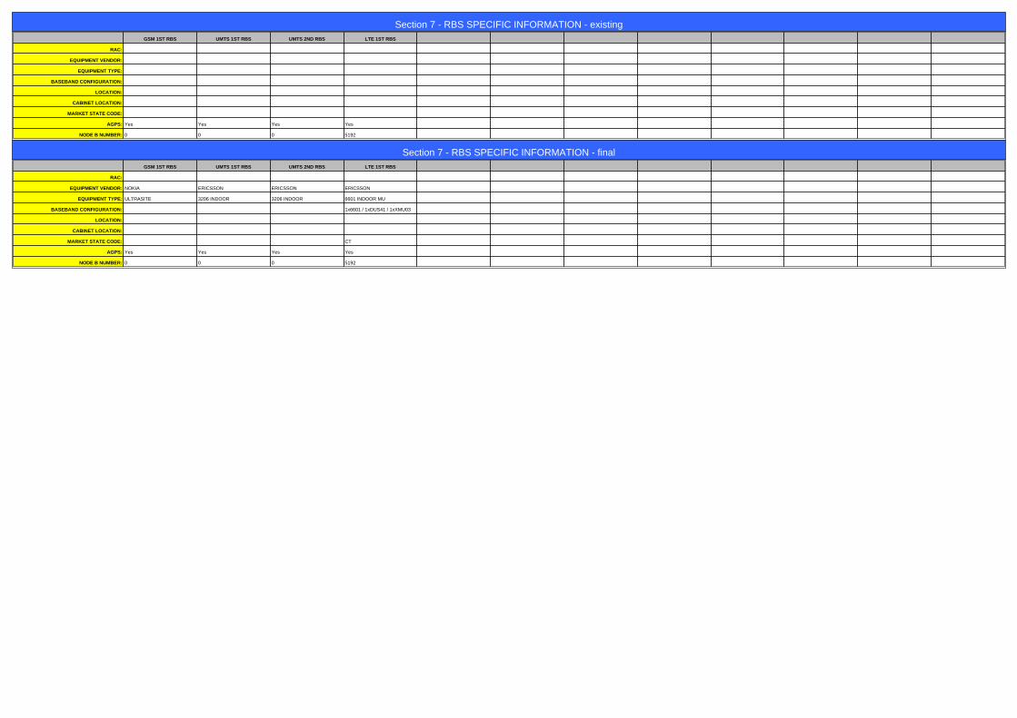
Section 7 - RBS SPECIFIC INFORMATION - existingGSM 1ST RBS UMTS 1ST RBS UMTS 2ND RBS LTE 1ST RBS
RAC:
EQUIPMENT VENDOR:
EQUIPMENT TYPE:
BASEBAND CONFIGURATION:
LOCATION:
CABINET LOCATION:
MARKET STATE CODE:
AGPS: Yes Yes Yes Yes
NODE B NUMBER: 0 0 0 5192
Section 7 - RBS SPECIFIC INFORMATION - finalGSM 1ST RBS UMTS 1ST RBS UMTS 2ND RBS LTE 1ST RBS
RAC:
EQUIPMENT VENDOR: NOKIA ERICSSON ERICSSON ERICSSON
EQUIPMENT TYPE: ULTRASITE 3206 INDOOR 3206 INDOOR 6601 INDOOR MU
BASEBAND CONFIGURATION: 1x6601 / 1xDUS41 / 1xXMU03
LOCATION:
CABINET LOCATION:
MARKET STATE CODE: CT
AGPS: Yes Yes Yes Yes
NODE B NUMBER: 0 0 0 5192

Section 8 - RBS/SECTOR ASSOCIATION - existingGSM 1ST RBS UMTS 1ST RBS UMTS 2ND RBS LTE 1ST RBS
CTS Common ID 184P5192 CTV5192 CTU5192 CTL05192
Soft Sector IDs 184P51921 CTV51921 CTU51927 CTL05192_7A_1
184P51922 CTV51922 CTU51928 CTL05192_7B_1
184P51923 CTV51923 CTU51929 CTL05192_7C_1
CTL05192_9A_1
CTL05192_9A_2
CTL05192_9B_1
CTL05192_9B_2
CTL05192_9C_1
CTL05192_9C_2
Section 8 - RBS/SECTOR ASSOCIATION - finalGSM 1ST RBS UMTS 1ST RBS UMTS 2ND RBS LTE 1ST RBS
CTS Common ID 184P5192 CTV5192 CTU5192 CTL05192
Soft Sector IDs 184P51921 CTV51921 CTU51927 CTL05192_7A_1
184P51922 CTV51922 CTU51928 CTL05192_7B_1
184P51923 CTV51923 CTU51929 CTL05192_7C_1
CTL05192_9A_1
CTL05192_9A_2
CTL05192_9B_1
CTL05192_9B_2
CTL05192_9C_1
CTL05192_9C_2
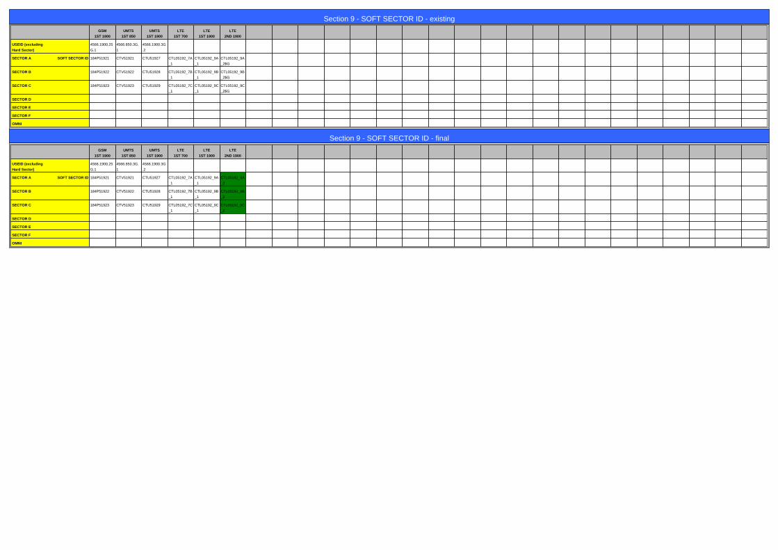
Section 9 - SOFT SECTOR ID - existing
GSM
1ST 1900
UMTS
1ST 850
UMTS
1ST 1900
LTE
1ST 700
LTE
1ST 1900
LTE
2ND 1900
USEID (excluding
Hard Sector)
4566.1900.25
G.1
4566.850.3G.
1
4566.1900.3G
.2
SECTOR A SOFT SECTOR ID 184P51921 CTV51921 CTU51927 CTL05192_7A
_1
CTL05192_9A
_1
CTL05192_9A
_2$G
SECTOR B 184P51922 CTV51922 CTU51928 CTL05192_7B
_1
CTL05192_9B
_1
CTL05192_9B
_2$G
SECTOR C 184P51923 CTV51923 CTU51929 CTL05192_7C
_1
CTL05192_9C
_1
CTL05192_9C
_2$G
SECTOR D
SECTOR E
SECTOR F
OMNI
Section 9 - SOFT SECTOR ID - final
GSM
1ST 1900
UMTS
1ST 850
UMTS
1ST 1900
LTE
1ST 700
LTE
1ST 1900
LTE
2ND 1900
USEID (excluding
Hard Sector)
4566.1900.25
G.1
4566.850.3G.
1
4566.1900.3G
.2
SECTOR A SOFT SECTOR ID 184P51921 CTV51921 CTU51927 CTL05192_7A
_1
CTL05192_9A
_1
CTL05192_9A
_2
SECTOR B 184P51922 CTV51922 CTU51928 CTL05192_7B
_1
CTL05192_9B
_1
CTL05192_9B
_2
SECTOR C 184P51923 CTV51923 CTU51929 CTL05192_7C
_1
CTL05192_9C
_1
CTL05192_9C
_2
SECTOR D
SECTOR E
SECTOR F
OMNI
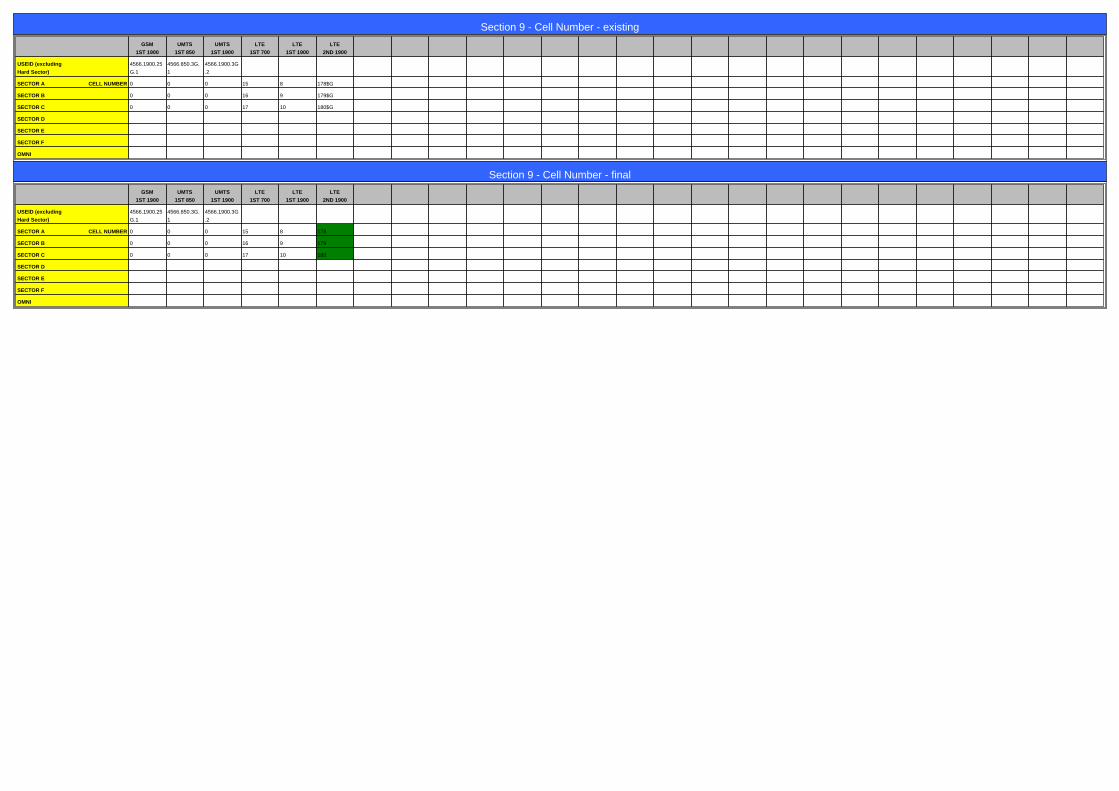
Section 9 - Cell Number - existing
GSM
1ST 1900
UMTS
1ST 850
UMTS
1ST 1900
LTE
1ST 700
LTE
1ST 1900
LTE
2ND 1900
USEID (excluding
Hard Sector)
4566.1900.25
G.1
4566.850.3G.
1
4566.1900.3G
.2
SECTOR A CELL NUMBER 0 0 0 15 8 178$G
SECTOR B 0 0 0 16 9 179$G
SECTOR C 0 0 0 17 10 180$G
SECTOR D
SECTOR E
SECTOR F
OMNI
Section 9 - Cell Number - final
GSM
1ST 1900
UMTS
1ST 850
UMTS
1ST 1900
LTE
1ST 700
LTE
1ST 1900
LTE
2ND 1900
USEID (excluding
Hard Sector)
4566.1900.25
G.1
4566.850.3G.
1
4566.1900.3G
.2
SECTOR A CELL NUMBER 0 0 0 15 8 178
SECTOR B 0 0 0 16 9 179
SECTOR C 0 0 0 17 10 180
SECTOR D
SECTOR E
SECTOR F
OMNI
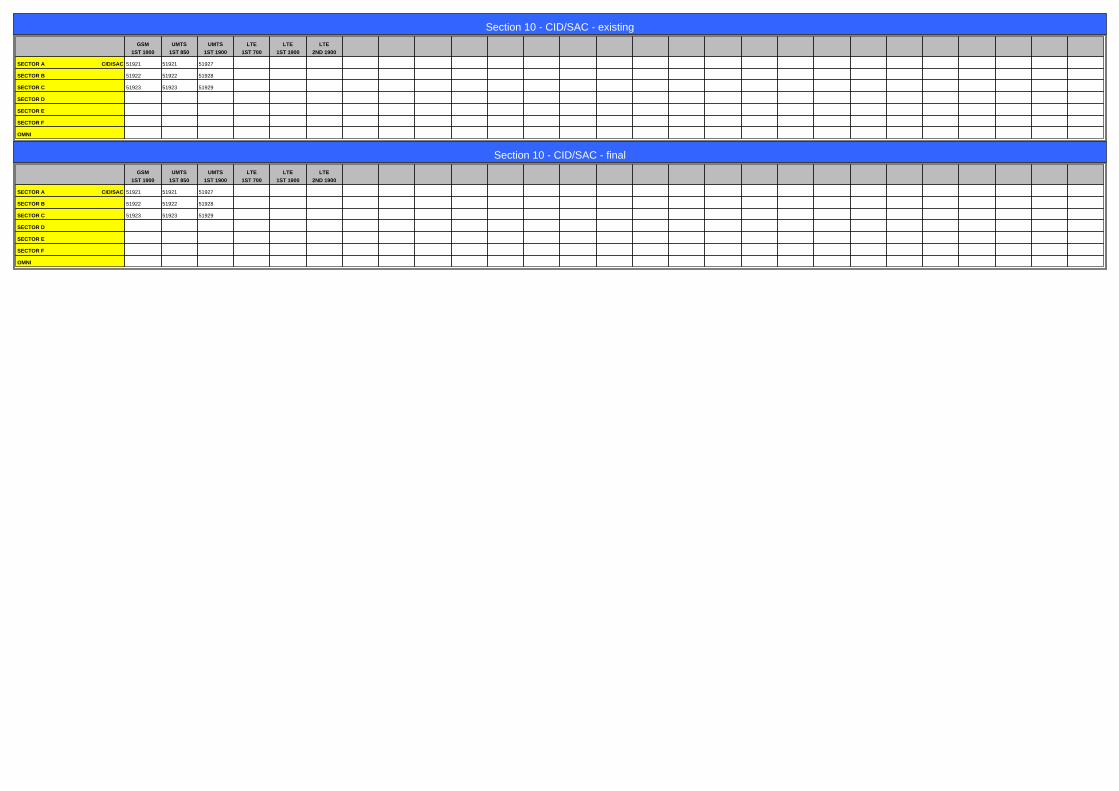
Section 10 - CID/SAC - existing
GSM
1ST 1900
UMTS
1ST 850
UMTS
1ST 1900
LTE
1ST 700
LTE
1ST 1900
LTE
2ND 1900
SECTOR A CID/SAC 51921 51921 51927
SECTOR B 51922 51922 51928
SECTOR C 51923 51923 51929
SECTOR D
SECTOR E
SECTOR F
OMNI
Section 10 - CID/SAC - final
GSM
1ST 1900
UMTS
1ST 850
UMTS
1ST 1900
LTE
1ST 700
LTE
1ST 1900
LTE
2ND 1900
SECTOR A CID/SAC 51921 51921 51927
SECTOR B 51922 51922 51928
SECTOR C 51923 51923 51929
SECTOR D
SECTOR E
SECTOR F
OMNI

Section 12 - CURRENT T1 COUNTS existing
LTE 1ST Cabinet
# T1s
LINK PROFILE
RF COMBINING
FIBER or ETHERNET?
Tx Board Model
Tx Board QTY
RAX/ECU Board Model
RAX/ECU Board QTY
BBU Board Model DUS41
BBU Board QTY 1
RRU - location
FIBER JUMPER
DC CABLE
DC/Fiber Dem. Box
Bundled Fiber Cable
Bundled DC Cable
Section 14 - NEW/PROPOSED T1 COUNTS
LTE 1ST Cabinet
# T1s
LINK PROFILE
RF COMBINING
FIBER or ETHERNET?
Tx Board Model
Tx Board QTY
RAX/ECU Board Model
RAX/ECU Board QTY
BBU Board Model DUS41
BBU Board QTY 1
RRU - location
FIBER JUMPER
DC CABLE
DC/Fiber Dem. Box
Bundled Fiber Cable
Bundled DC Cable
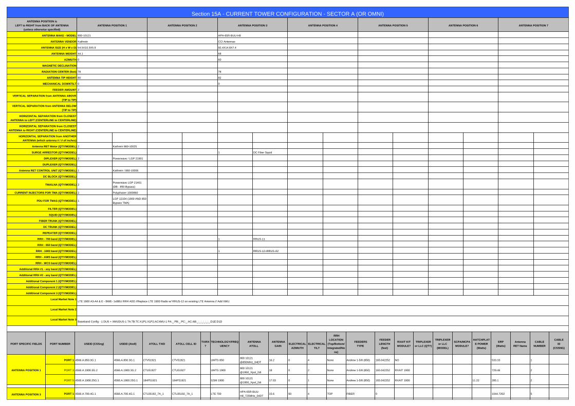
Section 15A - CURRENT TOWER CONFIGURATION - SECTOR A (OR OMNI)ANTENNA POSITION is
LEFT to RIGHT from BACK OF ANTENNA
(unless otherwise specified)
ANTENNA POSITION 1 ANTENNA POSITION 2 ANTENNA POSITION 3 ANTENNA POSITION 4 ANTENNA POSITION 5 ANTENNA POSITION 6 ANTENNA POSITION 7
ANTENNA MAKE - MODEL 800-10121 HPA-65R-BUU-H8
ANTENNA VENDOR Kathrein CCI Antennas
ANTENNA SIZE (H x W x D) 54.5X10.3X5.9 92.4X14.8X7.4
ANTENNA WEIGHT 44.1 68
AZIMUTH 0 60
MAGNETIC DECLINATION
RADIATION CENTER (feet) 78 78
ANTENNA TIP HEIGHT 80 82
MECHANICAL DOWNTILT 0 0
FEEDER AMOUNT 2
VERTICAL SEPARATION from ANTENNA ABOVE
(TIP to TIP)
VERTICAL SEPARATION from ANTENNA BELOW
(TIP to TIP)
HORIZONTAL SEPARATION from CLOSEST
ANTENNA to LEFT (CENTERLINE to CENTERLINE)
HORIZONTAL SEPARATION from CLOSEST
ANTENNA to RIGHT (CENTERLINE to CENTERLINE)
HORIZONTAL SEPARATION from ANOTHER
ANTENNA (which antenna # / # of inches)
Antenna RET Motor (QTY/MODEL) 2 Kathrein 860-10025
SURGE ARRESTOR (QTY/MODEL) 1 DC Fiber Squid
DIPLEXER (QTY/MODEL) 2 Powerwave / LGP 21901
DUPLEXER (QTY/MODEL)
Antenna RET CONTROL UNIT (QTY/MODEL) 1 Kathrein / 860-10006
DC BLOCK (QTY/MODEL)
TMA/LNA (QTY/MODEL) 2Powerwave LGP 21401
(DB - 850 Bypass)
CURRENT INJECTORS FOR TMA (QTY/MODEL) 2 Polyphaser 1000860
PDU FOR TMAS (QTY/MODEL) 1LGP 12104 (1900 AND 850
Bypass TMA)
FILTER (QTY/MODEL)
SQUID (QTY/MODEL)
FIBER TRUNK (QTY/MODEL)
DC TRUNK (QTY/MODEL)
REPEATER (QTY/MODEL)
RRH - 700 band (QTY/MODEL) 1 RRUS-11
RRH - 850 band (QTY/MODEL)
RRH - 1900 band (QTY/MODEL) 1 RRUS-12+RRUS-A2
RRH - AWS band (QTY/MODEL)
RRH - WCS band (QTY/MODEL)
Additional RRH #1 - any band (QTY/MODEL)
Additional RRH #2 - any band (QTY/MODEL)
Additional Component 1 (QTY/MODEL)
Additional Component 2 (QTY/MODEL)
Additional Component 3 (QTY/MODEL)
Local Market Note 1LTE 1900 A3-A4 & E - BWE- 1xBBU RRH ADD //Replace LTE 1900 Radio w/ RRUS-12 on existing LTE Antenna // Add XMU.
Local Market Note 2
Local Market Note 3Baseband Config - 1 DUS + XMUDUS-1 7A:7B:7C:X1P1:X1P2:ACXMU-1 PA:_:PB:_:PC:_:AC:AB:_:_:_:_:_:_:D1E:D1D
a
PORT SPECIFIC FIELDS PORT NUMBER USEID (CSSng) USEID (Atoll) ATOLL TXID ATOLL CELL IDTX/RX
?
TECHNOLOGY/FREQ
UENCY
ANTENNA
ATOLL
ANTENNA
GAIN
ELECTRICAL
AZIMUTH
ELECTRICAL
TILT
RRH
LOCATION
(Top/Bottom/
Integrated/No
ne)
FEEDERS
TYPE
FEEDER
LENGTH
(feet)
RXAIT KIT
MODULE?
TRIPLEXER
or LLC (QTY)
TRIPLEXER
or LLC
(MODEL)
SCPA/MCPA
MODULE?
HATCHPLAT
E POWER
(Watts)
ERP
(Watts)
Antenna
RET Name
CABLE
NUMBER
CABLE
ID
(CSSNG)
ANTENNA POSITION 1
PORT 1 4566.A.850.3G.1 4566.A.850.3G.1 CTV51921 CTV51921 UMTS 850800 10121
@850MHz_04DT16.2 0 4 None Andrew 1-5/8 (850) 165.042252 NO 533.33 1
PORT 3 4566.A.1900.3G.2 4566.A.1900.3G.2 CTU51927 CTU51927 UMTS 1900800 10121
@1950_Xpol_2dt18 0 2 None Andrew 1-5/8 (850) 165.042252 RXAIT 1900 729.46 2
PORT 5 4566.A.1900.25G.1 4566.A.1900.25G.1 184P51921 184P51921 GSM 1900800 10121
@1950_Xpol_2dt17.03 0 1 None Andrew 1-5/8 (850) 165.042252 RXAIT 1900 11.22 285.1 2
a
ANTENNA POSITION 3 PORT 1 4566.A.700.4G.1 4566.A.700.4G.1 CTL05192_7A_1 CTL05192_7A_1 LTE 700HPA-65R-BUU-
H8_725MHz_04DT15.6 60 4 TOP FIBER 0 1044.7202 5

PORT 3 4566.A.1900.4G.1 4566.A.1900.4G.1 CTL05192_9A_1 CTL05192_9A_1 LTE 1900HPA-65R-BUU-
H8_1948MHz_05DT17.29 60 5 TOP FIBER 0 2233.5722 5
PORT 4 4566.A.1900.4G.tmp2 4566.A.1900.4G.tmp2 CTL05192_9A_2 CTL05192_9A_2 LTE 1900HPA-65R-BUU-
H8_1948MHz_05DT17.29 60 5 TOP FIBER 0 2233.5722 5

Section 15B - CURRENT TOWER CONFIGURATION - SECTOR BANTENNA POSITION is
LEFT to RIGHT from BACK OF ANTENNA
(unless otherwise specified)
ANTENNA POSITION 1 ANTENNA POSITION 2 ANTENNA POSITION 3 ANTENNA POSITION 4 ANTENNA POSITION 5 ANTENNA POSITION 6 ANTENNA POSITION 7
ANTENNA MAKE - MODEL 800-10121 HPA-65R-BUU-H8
ANTENNA VENDOR Kathrein CCI Antennas
ANTENNA SIZE (H x W x D) 54.5X10.3X5.9 92.4X14.8X7.4
ANTENNA WEIGHT 44.1 68
AZIMUTH 120 170
MAGNETIC DECLINATION
RADIATION CENTER (feet) 78 78
ANTENNA TIP HEIGHT 80 82
MECHANICAL DOWNTILT 0 0
FEEDER AMOUNT 2
VERTICAL SEPARATION from ANTENNA ABOVE
(TIP to TIP)
VERTICAL SEPARATION from ANTENNA BELOW
(TIP to TIP)
HORIZONTAL SEPARATION from CLOSEST
ANTENNA to LEFT (CENTERLINE to CENTERLINE)
HORIZONTAL SEPARATION from CLOSEST
ANTENNA to RIGHT (CENTERLINE to CENTERLINE)
HORIZONTAL SEPARATION from ANOTHER
ANTENNA (which antenna # / # of inches)
Antenna RET Motor (QTY/MODEL) 2 Kathrein 860-10025
SURGE ARRESTOR (QTY/MODEL) 1 DC Fiber Squid
DIPLEXER (QTY/MODEL) 2 Powerwave / LGP 21901
DUPLEXER (QTY/MODEL)
Antenna RET CONTROL UNIT (QTY/MODEL)
DC BLOCK (QTY/MODEL)
TMA/LNA (QTY/MODEL) 2Powerwave LGP 21401
(DB - 850 Bypass)
CURRENT INJECTORS FOR TMA (QTY/MODEL) 2 Polyphaser 1000860
PDU FOR TMAS (QTY/MODEL)
FILTER (QTY/MODEL)
SQUID (QTY/MODEL)
FIBER TRUNK (QTY/MODEL)
DC TRUNK (QTY/MODEL)
REPEATER (QTY/MODEL)
RRH - 700 band (QTY/MODEL) 1 RRUS-11
RRH - 850 band (QTY/MODEL)
RRH - 1900 band (QTY/MODEL) 1 RRUS-12+RRUS-A2
RRH - AWS band (QTY/MODEL)
RRH - WCS band (QTY/MODEL)
Additional RRH #1 - any band (QTY/MODEL)
Additional RRH #2 - any band (QTY/MODEL)
Additional Component 1 (QTY/MODEL)
Additional Component 2 (QTY/MODEL)
Additional Component 3 (QTY/MODEL)
Local Market Note 1LTE 1900 A3-A4 & E - BWE- 1xBBU RRH ADD //Replace LTE 1900 Radio w/ RRUS-12 on existing LTE Antenna // Add XMU.
Local Market Note 2
Local Market Note 3Baseband Config - 1 DUS + XMUDUS-1 7A:7B:7C:X1P1:X1P2:ACXMU-1 PA:_:PB:_:PC:_:AC:AB:_:_:_:_:_:_:D1E:D1D
a
PORT SPECIFIC FIELDS PORT NUMBER USEID (CSSng) USEID (Atoll) ATOLL TXID ATOLL CELL IDTX/RX
?
TECHNOLOGY/FREQ
UENCY
ANTENNA
ATOLL
ANTENNA
GAIN
ELECTRICAL
AZIMUTH
ELECTRICAL
TILT
RRH
LOCATION
(Top/Bottom/
Integrated/No
ne)
FEEDERS
TYPE
FEEDER
LENGTH
(feet)
RXAIT KIT
MODULE?
TRIPLEXER
or LLC (QTY)
TRIPLEXER
or LLC
(MODEL)
SCPA/MCPA
MODULE?
HATCHPLAT
E POWER
(Watts)
ERP
(Watts)
Antenna
RET Name
CABLE
NUMBER
CABLE
ID
(CSSNG)
ANTENNA POSITION 1
PORT 1 4566.B.850.3G.1 4566.B.850.3G.1 CTV51922 CTV51922 UMTS 850
800 10121
@1950_840MHz_04D
T
17.2 120 4 None Andrew 1-5/8 (850) 165.042252 NO 770.9 9
PORT 3 4566.B.1900.3G.2 4566.B.1900.3G.2 CTU51928 CTU51928 UMTS 1900800 10121
@1950_Xpol_2dt17.5 120 2 None Andrew 1-5/8 (850) 165.042252 RXAIT 1900 650.13 10
PORT 5 4566.B.1900.25G.1 4566.B.1900.25G.1 184P51922 184P51922 GSM 1900800 10121
@1950_Xpol_7dt16.45 120 7 None Andrew 1-5/8 (850) 165.042252 RXAIT 1900 28.18 626.61 10
a
ANTENNA POSITION 3 PORT 1 4566.B.700.4G.1 4566.B.700.4G.1 CTL05192_7B_1 CTL05192_7B_1 LTE 700HPA-65R-BUU-
H8_719MHz_04DT16.39 170 4 TOP FIBER 0 1044.7202 13

PORT 3 4566.B.1900.4G.1 4566.B.1900.4G.1 CTL05192_9B_1 CTL05192_9B_1 LTE 1900HPA-65R-BUU-
H8_1948MHz_02DT16.89 170 2 TOP FIBER 0 2233.5722 13
PORT 4 4566.B.1900.4G.tmp2 4566.B.1900.4G.tmp2 CTL05192_9B_2 CTL05192_9B_2 LTE 1900HPA-65R-BUU-
H8_1948MHz_02DT16.89 170 2 TOP FIBER 0 2233.5722 13
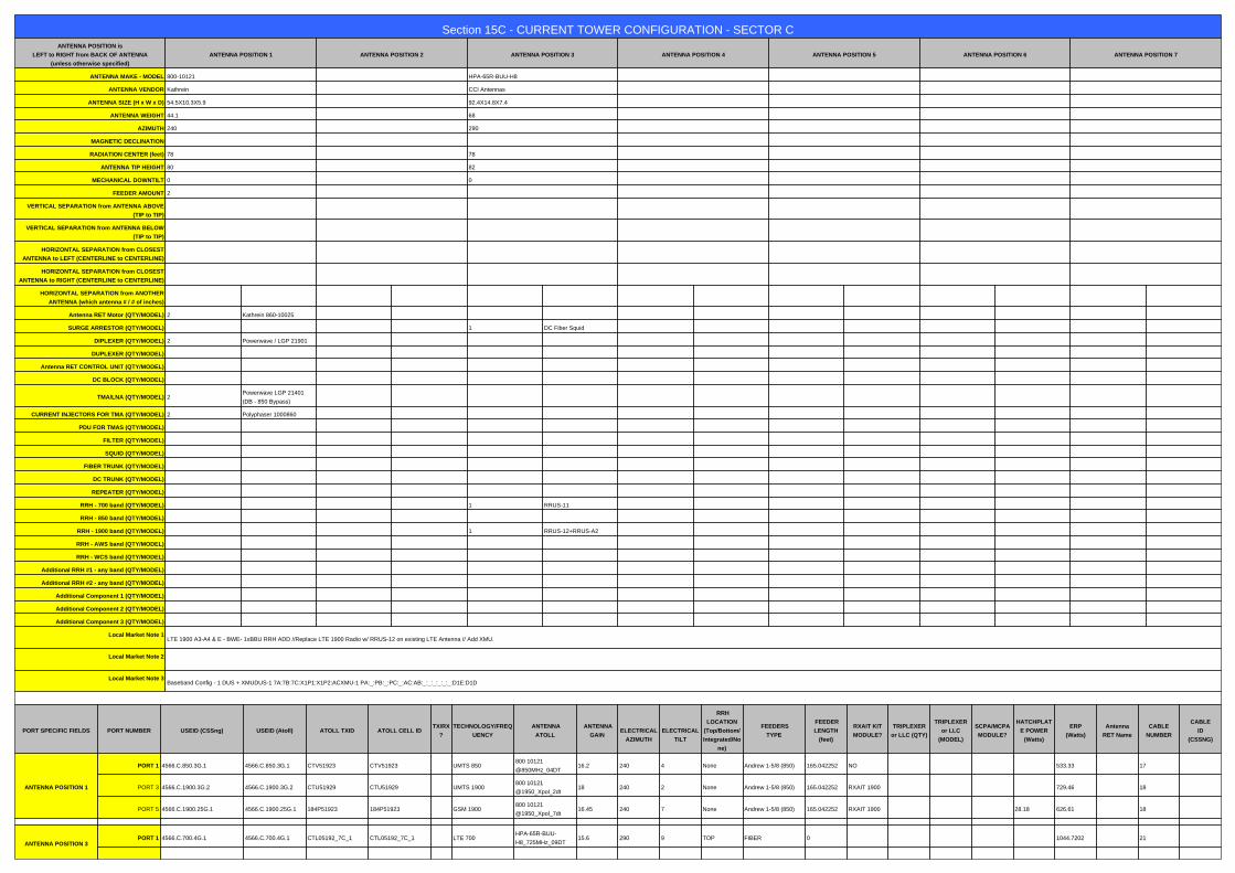
Section 15C - CURRENT TOWER CONFIGURATION - SECTOR CANTENNA POSITION is
LEFT to RIGHT from BACK OF ANTENNA
(unless otherwise specified)
ANTENNA POSITION 1 ANTENNA POSITION 2 ANTENNA POSITION 3 ANTENNA POSITION 4 ANTENNA POSITION 5 ANTENNA POSITION 6 ANTENNA POSITION 7
ANTENNA MAKE - MODEL 800-10121 HPA-65R-BUU-H8
ANTENNA VENDOR Kathrein CCI Antennas
ANTENNA SIZE (H x W x D) 54.5X10.3X5.9 92.4X14.8X7.4
ANTENNA WEIGHT 44.1 68
AZIMUTH 240 290
MAGNETIC DECLINATION
RADIATION CENTER (feet) 78 78
ANTENNA TIP HEIGHT 80 82
MECHANICAL DOWNTILT 0 0
FEEDER AMOUNT 2
VERTICAL SEPARATION from ANTENNA ABOVE
(TIP to TIP)
VERTICAL SEPARATION from ANTENNA BELOW
(TIP to TIP)
HORIZONTAL SEPARATION from CLOSEST
ANTENNA to LEFT (CENTERLINE to CENTERLINE)
HORIZONTAL SEPARATION from CLOSEST
ANTENNA to RIGHT (CENTERLINE to CENTERLINE)
HORIZONTAL SEPARATION from ANOTHER
ANTENNA (which antenna # / # of inches)
Antenna RET Motor (QTY/MODEL) 2 Kathrein 860-10025
SURGE ARRESTOR (QTY/MODEL) 1 DC Fiber Squid
DIPLEXER (QTY/MODEL) 2 Powerwave / LGP 21901
DUPLEXER (QTY/MODEL)
Antenna RET CONTROL UNIT (QTY/MODEL)
DC BLOCK (QTY/MODEL)
TMA/LNA (QTY/MODEL) 2Powerwave LGP 21401
(DB - 850 Bypass)
CURRENT INJECTORS FOR TMA (QTY/MODEL) 2 Polyphaser 1000860
PDU FOR TMAS (QTY/MODEL)
FILTER (QTY/MODEL)
SQUID (QTY/MODEL)
FIBER TRUNK (QTY/MODEL)
DC TRUNK (QTY/MODEL)
REPEATER (QTY/MODEL)
RRH - 700 band (QTY/MODEL) 1 RRUS-11
RRH - 850 band (QTY/MODEL)
RRH - 1900 band (QTY/MODEL) 1 RRUS-12+RRUS-A2
RRH - AWS band (QTY/MODEL)
RRH - WCS band (QTY/MODEL)
Additional RRH #1 - any band (QTY/MODEL)
Additional RRH #2 - any band (QTY/MODEL)
Additional Component 1 (QTY/MODEL)
Additional Component 2 (QTY/MODEL)
Additional Component 3 (QTY/MODEL)
Local Market Note 1LTE 1900 A3-A4 & E - BWE- 1xBBU RRH ADD //Replace LTE 1900 Radio w/ RRUS-12 on existing LTE Antenna // Add XMU.
Local Market Note 2
Local Market Note 3Baseband Config - 1 DUS + XMUDUS-1 7A:7B:7C:X1P1:X1P2:ACXMU-1 PA:_:PB:_:PC:_:AC:AB:_:_:_:_:_:_:D1E:D1D
a
PORT SPECIFIC FIELDS PORT NUMBER USEID (CSSng) USEID (Atoll) ATOLL TXID ATOLL CELL IDTX/RX
?
TECHNOLOGY/FREQ
UENCY
ANTENNA
ATOLL
ANTENNA
GAIN
ELECTRICAL
AZIMUTH
ELECTRICAL
TILT
RRH
LOCATION
(Top/Bottom/
Integrated/No
ne)
FEEDERS
TYPE
FEEDER
LENGTH
(feet)
RXAIT KIT
MODULE?
TRIPLEXER
or LLC (QTY)
TRIPLEXER
or LLC
(MODEL)
SCPA/MCPA
MODULE?
HATCHPLAT
E POWER
(Watts)
ERP
(Watts)
Antenna
RET Name
CABLE
NUMBER
CABLE
ID
(CSSNG)
ANTENNA POSITION 1
PORT 1 4566.C.850.3G.1 4566.C.850.3G.1 CTV51923 CTV51923 UMTS 850800 10121
@850MHz_04DT16.2 240 4 None Andrew 1-5/8 (850) 165.042252 NO 533.33 17
PORT 3 4566.C.1900.3G.2 4566.C.1900.3G.2 CTU51929 CTU51929 UMTS 1900800 10121
@1950_Xpol_2dt18 240 2 None Andrew 1-5/8 (850) 165.042252 RXAIT 1900 729.46 18
PORT 5 4566.C.1900.25G.1 4566.C.1900.25G.1 184P51923 184P51923 GSM 1900800 10121
@1950_Xpol_7dt16.45 240 7 None Andrew 1-5/8 (850) 165.042252 RXAIT 1900 28.18 626.61 18
a
ANTENNA POSITION 3PORT 1 4566.C.700.4G.1 4566.C.700.4G.1 CTL05192_7C_1 CTL05192_7C_1 LTE 700
HPA-65R-BUU-
H8_725MHz_09DT15.6 290 9 TOP FIBER 0 1044.7202 21

PORT 3 4566.C.1900.4G.1 4566.C.1900.4G.1 CTL05192_9C_1 CTL05192_9C_1 LTE 1900HPA-65R-BUU-
H8_1948MHz_06DT17.39 290 6 TOP FIBER 0 2233.5722 21
PORT 4 4566.C.1900.4G.tmp2 4566.C.1900.4G.tmp2 CTL05192_9C_2 CTL05192_9C_2 LTE 1900HPA-65R-BUU-
H8_1948MHz_06DT17.39 290 6 TOP FIBER 0 2233.5722 21
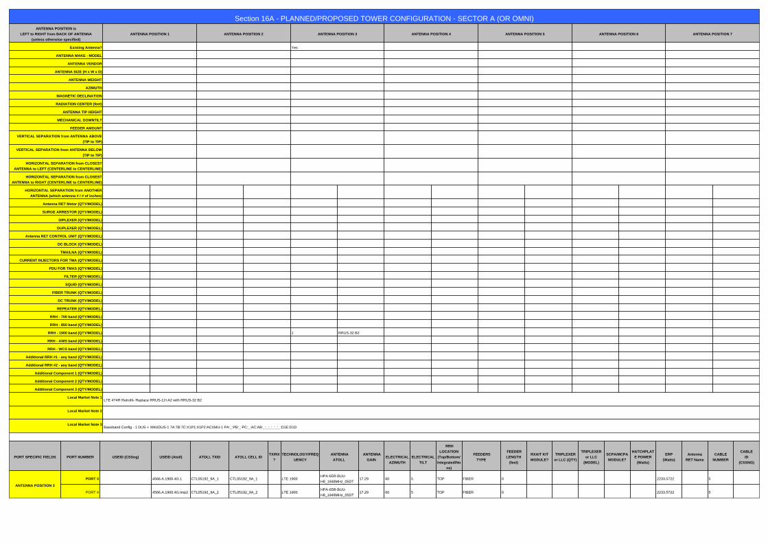
Section 16A - PLANNED/PROPOSED TOWER CONFIGURATION - SECTOR A (OR OMNI)ANTENNA POSITION is
LEFT to RIGHT from BACK OF ANTENNA
(unless otherwise specified)
ANTENNA POSITION 1 ANTENNA POSITION 2 ANTENNA POSITION 3 ANTENNA POSITION 4 ANTENNA POSITION 5 ANTENNA POSITION 6 ANTENNA POSITION 7
Existing Antenna? Yes
ANTENNA MAKE - MODEL
ANTENNA VENDOR
ANTENNA SIZE (H x W x D)
ANTENNA WEIGHT
AZIMUTH
MAGNETIC DECLINATION
RADIATION CENTER (feet)
ANTENNA TIP HEIGHT
MECHANICAL DOWNTILT
FEEDER AMOUNT
VERTICAL SEPARATION from ANTENNA ABOVE
(TIP to TIP)
VERTICAL SEPARATION from ANTENNA BELOW
(TIP to TIP)
HORIZONTAL SEPARATION from CLOSEST
ANTENNA to LEFT (CENTERLINE to CENTERLINE)
HORIZONTAL SEPARATION from CLOSEST
ANTENNA to RIGHT (CENTERLINE to CENTERLINE)
HORIZONTAL SEPARATION from ANOTHER
ANTENNA (which antenna # / # of inches)
Antenna RET Motor (QTY/MODEL)
SURGE ARRESTOR (QTY/MODEL)
DIPLEXER (QTY/MODEL)
DUPLEXER (QTY/MODEL)
Antenna RET CONTROL UNIT (QTY/MODEL)
DC BLOCK (QTY/MODEL)
TMA/LNA (QTY/MODEL)
CURRENT INJECTORS FOR TMA (QTY/MODEL)
PDU FOR TMAS (QTY/MODEL)
FILTER (QTY/MODEL)
SQUID (QTY/MODEL)
FIBER TRUNK (QTY/MODEL)
DC TRUNK (QTY/MODEL)
REPEATER (QTY/MODEL)
RRH - 700 band (QTY/MODEL)
RRH - 850 band (QTY/MODEL)
RRH - 1900 band (QTY/MODEL) 1 RRUS-32 B2
RRH - AWS band (QTY/MODEL)
RRH - WCS band (QTY/MODEL)
Additional RRH #1 - any band (QTY/MODEL)
Additional RRH #2 - any band (QTY/MODEL)
Additional Component 1 (QTY/MODEL)
Additional Component 2 (QTY/MODEL)
Additional Component 3 (QTY/MODEL)
Local Market Note 1LTE 4T4R Retrofit- Replace RRUS-12+A2 with RRUS-32 B2
Local Market Note 2
Local Market Note 3Baseband Config - 1 DUS + XMUDUS-1 7A:7B:7C:X1P1:X1P2:ACXMU-1 PA:_:PB:_:PC:_:AC:AB:_:_:_:_:_:_:D1E:D1D
a
PORT SPECIFIC FIELDS PORT NUMBER USEID (CSSng) USEID (Atoll) ATOLL TXID ATOLL CELL IDTX/RX
?
TECHNOLOGY/FREQ
UENCY
ANTENNA
ATOLL
ANTENNA
GAIN
ELECTRICAL
AZIMUTH
ELECTRICAL
TILT
RRH
LOCATION
(Top/Bottom/
Integrated/No
ne)
FEEDERS
TYPE
FEEDER
LENGTH
(feet)
RXAIT KIT
MODULE?
TRIPLEXER
or LLC (QTY)
TRIPLEXER
or LLC
(MODEL)
SCPA/MCPA
MODULE?
HATCHPLAT
E POWER
(Watts)
ERP
(Watts)
Antenna
RET Name
CABLE
NUMBER
CABLE
ID
(CSSNG)
ANTENNA POSITION 3
PORT 3 4566.A.1900.4G.1 CTL05192_9A_1 CTL05192_9A_1 LTE 1900HPA-65R-BUU-
H8_1948MHz_05DT17.29 60 5 TOP FIBER 0 2233.5722 5
PORT 4 4566.A.1900.4G.tmp2 CTL05192_9A_2 CTL05192_9A_2 LTE 1900HPA-65R-BUU-
H8_1948MHz_05DT17.29 60 5 TOP FIBER 0 2233.5722 5

Section 16B - PLANNED/PROPOSED TOWER CONFIGURATION - SECTOR BANTENNA POSITION is
LEFT to RIGHT from BACK OF ANTENNA
(unless otherwise specified)
ANTENNA POSITION 1 ANTENNA POSITION 2 ANTENNA POSITION 3 ANTENNA POSITION 4 ANTENNA POSITION 5 ANTENNA POSITION 6 ANTENNA POSITION 7
Existing Antenna? Yes
ANTENNA MAKE - MODEL
ANTENNA VENDOR
ANTENNA SIZE (H x W x D)
ANTENNA WEIGHT
AZIMUTH
MAGNETIC DECLINATION
RADIATION CENTER (feet)
ANTENNA TIP HEIGHT
MECHANICAL DOWNTILT
FEEDER AMOUNT
VERTICAL SEPARATION from ANTENNA ABOVE
(TIP to TIP)
VERTICAL SEPARATION from ANTENNA BELOW
(TIP to TIP)
HORIZONTAL SEPARATION from CLOSEST
ANTENNA to LEFT (CENTERLINE to CENTERLINE)
HORIZONTAL SEPARATION from CLOSEST
ANTENNA to RIGHT (CENTERLINE to CENTERLINE)
HORIZONTAL SEPARATION from ANOTHER
ANTENNA (which antenna # / # of inches)
Antenna RET Motor (QTY/MODEL)
SURGE ARRESTOR (QTY/MODEL)
DIPLEXER (QTY/MODEL)
DUPLEXER (QTY/MODEL)
Antenna RET CONTROL UNIT (QTY/MODEL)
DC BLOCK (QTY/MODEL)
TMA/LNA (QTY/MODEL)
CURRENT INJECTORS FOR TMA (QTY/MODEL)
PDU FOR TMAS (QTY/MODEL)
FILTER (QTY/MODEL)
SQUID (QTY/MODEL)
FIBER TRUNK (QTY/MODEL)
DC TRUNK (QTY/MODEL)
REPEATER (QTY/MODEL)
RRH - 700 band (QTY/MODEL)
RRH - 850 band (QTY/MODEL)
RRH - 1900 band (QTY/MODEL) 1 RRUS-32 B2
RRH - AWS band (QTY/MODEL)
RRH - WCS band (QTY/MODEL)
Additional RRH #1 - any band (QTY/MODEL)
Additional RRH #2 - any band (QTY/MODEL)
Additional Component 1 (QTY/MODEL)
Additional Component 2 (QTY/MODEL)
Additional Component 3 (QTY/MODEL)
Local Market Note 1LTE 4T4R Retrofit- Replace RRUS-12+A2 with RRUS-32 B2
Local Market Note 2
Local Market Note 3Baseband Config - 1 DUS + XMUDUS-1 7A:7B:7C:X1P1:X1P2:ACXMU-1 PA:_:PB:_:PC:_:AC:AB:_:_:_:_:_:_:D1E:D1D
a
PORT SPECIFIC FIELDS PORT NUMBER USEID (CSSng) USEID (Atoll) ATOLL TXID ATOLL CELL IDTX/RX
?
TECHNOLOGY/FREQ
UENCY
ANTENNA
ATOLL
ANTENNA
GAIN
ELECTRICAL
AZIMUTH
ELECTRICAL
TILT
RRH
LOCATION
(Top/Bottom/
Integrated/No
ne)
FEEDERS
TYPE
FEEDER
LENGTH
(feet)
RXAIT KIT
MODULE?
TRIPLEXER
or LLC (QTY)
TRIPLEXER
or LLC
(MODEL)
SCPA/MCPA
MODULE?
HATCHPLAT
E POWER
(Watts)
ERP
(Watts)
Antenna
RET Name
CABLE
NUMBER
CABLE
ID
(CSSNG)
ANTENNA POSITION 3
PORT 3 4566.B.1900.4G.1 CTL05192_9B_1 CTL05192_9B_1 LTE 1900HPA-65R-BUU-
H8_1948MHz_02DT16.89 170 2 TOP FIBER 0 2233.5722 13
PORT 4 4566.B.1900.4G.tmp2 CTL05192_9B_2 CTL05192_9B_2 LTE 1900HPA-65R-BUU-
H8_1948MHz_02DT16.89 170 2 TOP FIBER 0 2233.5722 13
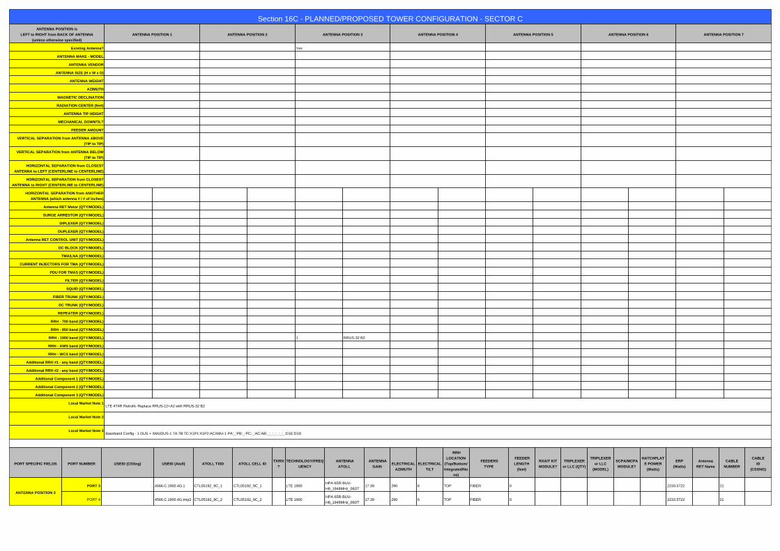
Section 16C - PLANNED/PROPOSED TOWER CONFIGURATION - SECTOR CANTENNA POSITION is
LEFT to RIGHT from BACK OF ANTENNA
(unless otherwise specified)
ANTENNA POSITION 1 ANTENNA POSITION 2 ANTENNA POSITION 3 ANTENNA POSITION 4 ANTENNA POSITION 5 ANTENNA POSITION 6 ANTENNA POSITION 7
Existing Antenna? Yes
ANTENNA MAKE - MODEL
ANTENNA VENDOR
ANTENNA SIZE (H x W x D)
ANTENNA WEIGHT
AZIMUTH
MAGNETIC DECLINATION
RADIATION CENTER (feet)
ANTENNA TIP HEIGHT
MECHANICAL DOWNTILT
FEEDER AMOUNT
VERTICAL SEPARATION from ANTENNA ABOVE
(TIP to TIP)
VERTICAL SEPARATION from ANTENNA BELOW
(TIP to TIP)
HORIZONTAL SEPARATION from CLOSEST
ANTENNA to LEFT (CENTERLINE to CENTERLINE)
HORIZONTAL SEPARATION from CLOSEST
ANTENNA to RIGHT (CENTERLINE to CENTERLINE)
HORIZONTAL SEPARATION from ANOTHER
ANTENNA (which antenna # / # of inches)
Antenna RET Motor (QTY/MODEL)
SURGE ARRESTOR (QTY/MODEL)
DIPLEXER (QTY/MODEL)
DUPLEXER (QTY/MODEL)
Antenna RET CONTROL UNIT (QTY/MODEL)
DC BLOCK (QTY/MODEL)
TMA/LNA (QTY/MODEL)
CURRENT INJECTORS FOR TMA (QTY/MODEL)
PDU FOR TMAS (QTY/MODEL)
FILTER (QTY/MODEL)
SQUID (QTY/MODEL)
FIBER TRUNK (QTY/MODEL)
DC TRUNK (QTY/MODEL)
REPEATER (QTY/MODEL)
RRH - 700 band (QTY/MODEL)
RRH - 850 band (QTY/MODEL)
RRH - 1900 band (QTY/MODEL) 1 RRUS-32 B2
RRH - AWS band (QTY/MODEL)
RRH - WCS band (QTY/MODEL)
Additional RRH #1 - any band (QTY/MODEL)
Additional RRH #2 - any band (QTY/MODEL)
Additional Component 1 (QTY/MODEL)
Additional Component 2 (QTY/MODEL)
Additional Component 3 (QTY/MODEL)
Local Market Note 1LTE 4T4R Retrofit- Replace RRUS-12+A2 with RRUS-32 B2
Local Market Note 2
Local Market Note 3Baseband Config - 1 DUS + XMUDUS-1 7A:7B:7C:X1P1:X1P2:ACXMU-1 PA:_:PB:_:PC:_:AC:AB:_:_:_:_:_:_:D1E:D1D
a
PORT SPECIFIC FIELDS PORT NUMBER USEID (CSSng) USEID (Atoll) ATOLL TXID ATOLL CELL IDTX/RX
?
TECHNOLOGY/FREQ
UENCY
ANTENNA
ATOLL
ANTENNA
GAIN
ELECTRICAL
AZIMUTH
ELECTRICAL
TILT
RRH
LOCATION
(Top/Bottom/
Integrated/No
ne)
FEEDERS
TYPE
FEEDER
LENGTH
(feet)
RXAIT KIT
MODULE?
TRIPLEXER
or LLC (QTY)
TRIPLEXER
or LLC
(MODEL)
SCPA/MCPA
MODULE?
HATCHPLAT
E POWER
(Watts)
ERP
(Watts)
Antenna
RET Name
CABLE
NUMBER
CABLE
ID
(CSSNG)
ANTENNA POSITION 3
PORT 3 4566.C.1900.4G.1 CTL05192_9C_1 CTL05192_9C_1 LTE 1900HPA-65R-BUU-
H8_1948MHz_06DT17.39 290 6 TOP FIBER 0 2233.5722 21
PORT 4 4566.C.1900.4G.tmp2 CTL05192_9C_2 CTL05192_9C_2 LTE 1900HPA-65R-BUU-
H8_1948MHz_06DT17.39 290 6 TOP FIBER 0 2233.5722 21
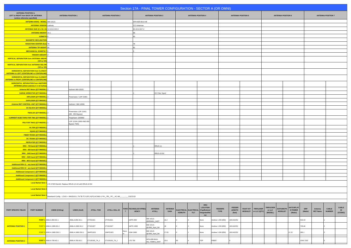
Section 17A - FINAL TOWER CONFIGURATION - SECTOR A (OR OMNI)ANTENNA POSITION is
LEFT to RIGHT from BACK OF ANTENNA
(unless otherwise specified)
ANTENNA POSITION 1 ANTENNA POSITION 2 ANTENNA POSITION 3 ANTENNA POSITION 4 ANTENNA POSITION 5 ANTENNA POSITION 6 ANTENNA POSITION 7
ANTENNA MAKE - MODEL 800-10121 HPA-65R-BUU-H8
ANTENNA VENDOR Kathrein CCI Antennas
ANTENNA SIZE (H x W x D) 54.5X10.3X5.9 92.4X14.8X7.4
ANTENNA WEIGHT 44.1 68
AZIMUTH 0 60
MAGNETIC DECLINATION
RADIATION CENTER (feet) 78 78
ANTENNA TIP HEIGHT 80 82
MECHANICAL DOWNTILT 0 0
FEEDER AMOUNT 2
VERTICAL SEPARATION from ANTENNA ABOVE
(TIP to TIP)
VERTICAL SEPARATION from ANTENNA BELOW
(TIP to TIP)
HORIZONTAL SEPARATION from CLOSEST
ANTENNA to LEFT (CENTERLINE to CENTERLINE)
HORIZONTAL SEPARATION from CLOSEST
ANTENNA to RIGHT (CENTERLINE to CENTERLINE)
HORIZONTAL SEPARATION from ANOTHER
ANTENNA (which antenna # / # of inches)
Antenna RET Motor (QTY/MODEL) 2 Kathrein 860-10025
SURGE ARRESTOR (QTY/MODEL) 1 DC Fiber Squid
DIPLEXER (QTY/MODEL) 2 Powerwave / LGP 21901
DUPLEXER (QTY/MODEL)
Antenna RET CONTROL UNIT (QTY/MODEL) 1 Kathrein / 860-10006
DC BLOCK (QTY/MODEL)
TMA/LNA (QTY/MODEL) 2Powerwave LGP 21401
(DB - 850 Bypass)
CURRENT INJECTORS FOR TMA (QTY/MODEL) 2 Polyphaser 1000860
PDU FOR TMAS (QTY/MODEL) 1LGP 12104 (1900 AND 850
Bypass TMA)
FILTER (QTY/MODEL)
SQUID (QTY/MODEL)
FIBER TRUNK (QTY/MODEL)
DC TRUNK (QTY/MODEL)
REPEATER (QTY/MODEL)
RRH - 700 band (QTY/MODEL) 1 RRUS-11
RRH - 850 band (QTY/MODEL)
RRH - 1900 band (QTY/MODEL) 1 RRUS-32 B2
RRH - AWS band (QTY/MODEL)
RRH - WCS band (QTY/MODEL)
Additional RRH #1 - any band (QTY/MODEL)
Additional RRH #2 - any band (QTY/MODEL)
Additional Component 1 (QTY/MODEL)
Additional Component 2 (QTY/MODEL)
Additional Component 3 (QTY/MODEL)
Local Market Note 1LTE 4T4R Retrofit- Replace RRUS-12+A2 with RRUS-32 B2
Local Market Note 2
Local Market Note 3Baseband Config - 1 DUS + XMUDUS-1 7A:7B:7C:X1P1:X1P2:ACXMU-1 PA:_:PB:_:PC:_:AC:AB:_:_:_:_:_:_:D1E:D1D
a
PORT SPECIFIC FIELDS PORT NUMBER USEID (CSSng) USEID (Atoll) ATOLL TXID ATOLL CELL IDTX/RX
?
TECHNOLOGY/FREQ
UENCY
ANTENNA
ATOLL
ANTENNA
GAIN
ELECTRICAL
AZIMUTH
ELECTRICAL
TILT
RRH
LOCATION
(Top/Bottom/
Integrated/No
ne)
FEEDERS
TYPE
FEEDER
LENGTH
(feet)
RXAIT KIT
MODULE?
TRIPLEXER
or LLC (QTY)
TRIPLEXER
or LLC
(MODEL)
SCPA/MCPA
MODULE?
HATCHPLAT
E POWER
(Watts)
ERP
(Watts)
Antenna
RET Name
CABLE
NUMBER
CABLE
ID
(CSSNG)
ANTENNA POSITION 1
PORT 1 4566.A.850.3G.1 4566.A.850.3G.1 CTV51921 CTV51921 UMTS 850800 10121
@850MHz_04DT16.2 0 4 None Andrew 1-5/8 (850) 165.042252 533.33 1
PORT 3 4566.A.1900.3G.2 4566.A.1900.3G.2 CTU51927 CTU51927 UMTS 1900800 10121
@1950_Xpol_2dt18 0 2 None Andrew 1-5/8 (850) 165.042252 729.46 2
PORT 5 4566.A.1900.25G.1 4566.A.1900.25G.1 184P51921 184P51921Deco
mGSM 1900
800 10121
@1950_Xpol_2dt17.03 0 1 None Andrew 1-5/8 (850) 165.042252 11.22 285.1 2
a
ANTENNA POSITION 3 PORT 1 4566.A.700.4G.1 4566.A.700.4G.1 CTL05192_7A_1 CTL05192_7A_1 LTE 700HPA-65R-BUU-
H8_725MHz_04DT15.6 60 4 TOP FIBER 0 1044.7202 5
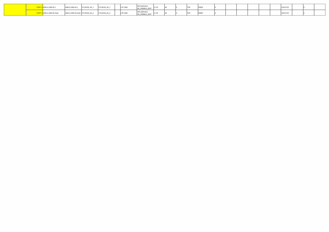
PORT 3 4566.A.1900.4G.1 4566.A.1900.4G.1 CTL05192_9A_1 CTL05192_9A_1 LTE 1900HPA-65R-BUU-
H8_1948MHz_05DT17.29 60 5 TOP FIBER 0 2233.5722 5
PORT 4 4566.A.1900.4G.tmp2 4566.A.1900.4G.tmp2 CTL05192_9A_2 CTL05192_9A_2 LTE 1900HPA-65R-BUU-
H8_1948MHz_05DT17.29 60 5 TOP FIBER 0 2233.5722 5
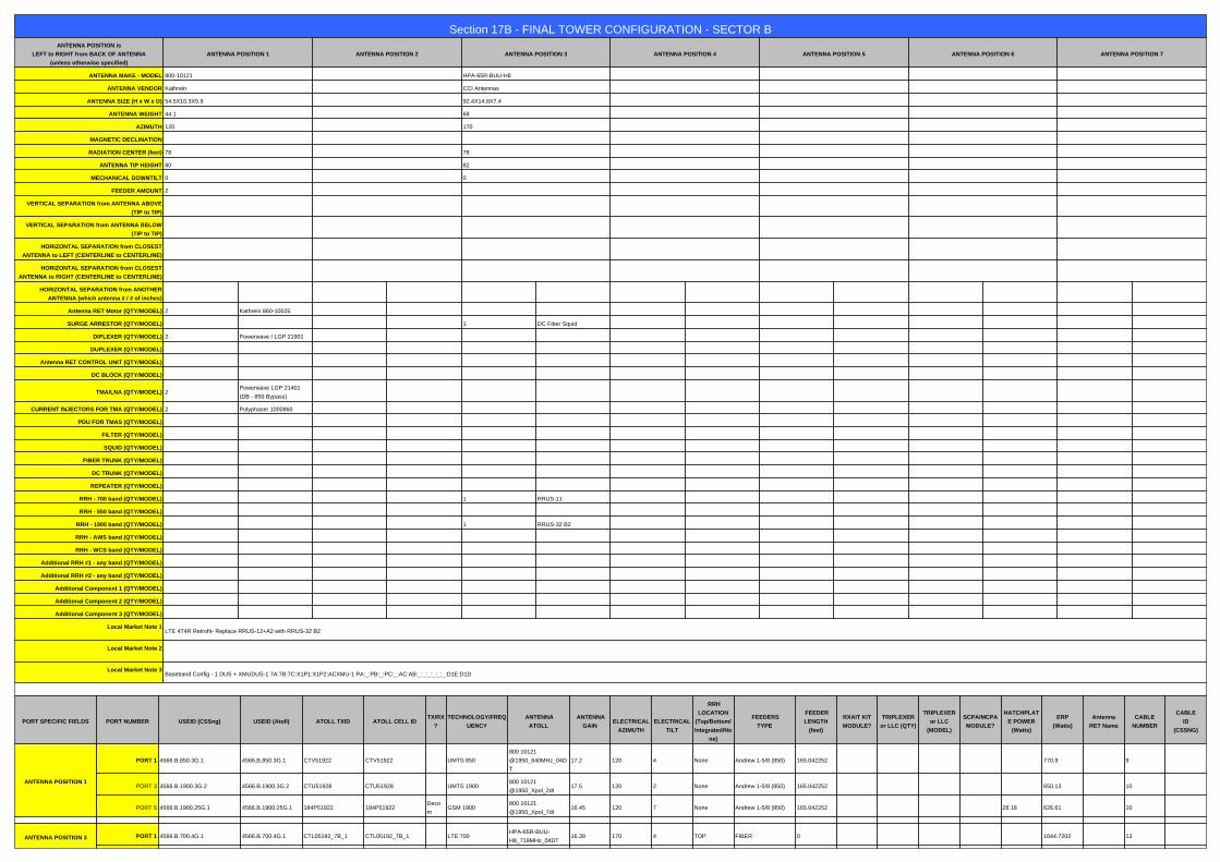
Section 17B - FINAL TOWER CONFIGURATION - SECTOR BANTENNA POSITION is
LEFT to RIGHT from BACK OF ANTENNA
(unless otherwise specified)
ANTENNA POSITION 1 ANTENNA POSITION 2 ANTENNA POSITION 3 ANTENNA POSITION 4 ANTENNA POSITION 5 ANTENNA POSITION 6 ANTENNA POSITION 7
ANTENNA MAKE - MODEL 800-10121 HPA-65R-BUU-H8
ANTENNA VENDOR Kathrein CCI Antennas
ANTENNA SIZE (H x W x D) 54.5X10.3X5.9 92.4X14.8X7.4
ANTENNA WEIGHT 44.1 68
AZIMUTH 120 170
MAGNETIC DECLINATION
RADIATION CENTER (feet) 78 78
ANTENNA TIP HEIGHT 80 82
MECHANICAL DOWNTILT 0 0
FEEDER AMOUNT 2
VERTICAL SEPARATION from ANTENNA ABOVE
(TIP to TIP)
VERTICAL SEPARATION from ANTENNA BELOW
(TIP to TIP)
HORIZONTAL SEPARATION from CLOSEST
ANTENNA to LEFT (CENTERLINE to CENTERLINE)
HORIZONTAL SEPARATION from CLOSEST
ANTENNA to RIGHT (CENTERLINE to CENTERLINE)
HORIZONTAL SEPARATION from ANOTHER
ANTENNA (which antenna # / # of inches)
Antenna RET Motor (QTY/MODEL) 2 Kathrein 860-10025
SURGE ARRESTOR (QTY/MODEL) 1 DC Fiber Squid
DIPLEXER (QTY/MODEL) 2 Powerwave / LGP 21901
DUPLEXER (QTY/MODEL)
Antenna RET CONTROL UNIT (QTY/MODEL)
DC BLOCK (QTY/MODEL)
TMA/LNA (QTY/MODEL) 2Powerwave LGP 21401
(DB - 850 Bypass)
CURRENT INJECTORS FOR TMA (QTY/MODEL) 2 Polyphaser 1000860
PDU FOR TMAS (QTY/MODEL)
FILTER (QTY/MODEL)
SQUID (QTY/MODEL)
FIBER TRUNK (QTY/MODEL)
DC TRUNK (QTY/MODEL)
REPEATER (QTY/MODEL)
RRH - 700 band (QTY/MODEL) 1 RRUS-11
RRH - 850 band (QTY/MODEL)
RRH - 1900 band (QTY/MODEL) 1 RRUS-32 B2
RRH - AWS band (QTY/MODEL)
RRH - WCS band (QTY/MODEL)
Additional RRH #1 - any band (QTY/MODEL)
Additional RRH #2 - any band (QTY/MODEL)
Additional Component 1 (QTY/MODEL)
Additional Component 2 (QTY/MODEL)
Additional Component 3 (QTY/MODEL)
Local Market Note 1LTE 4T4R Retrofit- Replace RRUS-12+A2 with RRUS-32 B2
Local Market Note 2
Local Market Note 3Baseband Config - 1 DUS + XMUDUS-1 7A:7B:7C:X1P1:X1P2:ACXMU-1 PA:_:PB:_:PC:_:AC:AB:_:_:_:_:_:_:D1E:D1D
a
PORT SPECIFIC FIELDS PORT NUMBER USEID (CSSng) USEID (Atoll) ATOLL TXID ATOLL CELL IDTX/RX
?
TECHNOLOGY/FREQ
UENCY
ANTENNA
ATOLL
ANTENNA
GAIN
ELECTRICAL
AZIMUTH
ELECTRICAL
TILT
RRH
LOCATION
(Top/Bottom/
Integrated/No
ne)
FEEDERS
TYPE
FEEDER
LENGTH
(feet)
RXAIT KIT
MODULE?
TRIPLEXER
or LLC (QTY)
TRIPLEXER
or LLC
(MODEL)
SCPA/MCPA
MODULE?
HATCHPLAT
E POWER
(Watts)
ERP
(Watts)
Antenna
RET Name
CABLE
NUMBER
CABLE
ID
(CSSNG)
ANTENNA POSITION 1
PORT 1 4566.B.850.3G.1 4566.B.850.3G.1 CTV51922 CTV51922 UMTS 850
800 10121
@1950_840MHz_04D
T
17.2 120 4 None Andrew 1-5/8 (850) 165.042252 770.9 9
PORT 3 4566.B.1900.3G.2 4566.B.1900.3G.2 CTU51928 CTU51928 UMTS 1900800 10121
@1950_Xpol_2dt17.5 120 2 None Andrew 1-5/8 (850) 165.042252 650.13 10
PORT 5 4566.B.1900.25G.1 4566.B.1900.25G.1 184P51922 184P51922Deco
mGSM 1900
800 10121
@1950_Xpol_7dt16.45 120 7 None Andrew 1-5/8 (850) 165.042252 28.18 626.61 10
a
ANTENNA POSITION 3 PORT 1 4566.B.700.4G.1 4566.B.700.4G.1 CTL05192_7B_1 CTL05192_7B_1 LTE 700HPA-65R-BUU-
H8_719MHz_04DT16.39 170 4 TOP FIBER 0 1044.7202 13

PORT 3 4566.B.1900.4G.1 4566.B.1900.4G.1 CTL05192_9B_1 CTL05192_9B_1 LTE 1900HPA-65R-BUU-
H8_1948MHz_02DT16.89 170 2 TOP FIBER 0 2233.5722 13
PORT 4 4566.B.1900.4G.tmp2 4566.B.1900.4G.tmp2 CTL05192_9B_2 CTL05192_9B_2 LTE 1900HPA-65R-BUU-
H8_1948MHz_02DT16.89 170 2 TOP FIBER 0 2233.5722 13

Section 17C - FINAL TOWER CONFIGURATION - SECTOR CANTENNA POSITION is
LEFT to RIGHT from BACK OF ANTENNA
(unless otherwise specified)
ANTENNA POSITION 1 ANTENNA POSITION 2 ANTENNA POSITION 3 ANTENNA POSITION 4 ANTENNA POSITION 5 ANTENNA POSITION 6 ANTENNA POSITION 7
ANTENNA MAKE - MODEL 800-10121 HPA-65R-BUU-H8
ANTENNA VENDOR Kathrein CCI Antennas
ANTENNA SIZE (H x W x D) 54.5X10.3X5.9 92.4X14.8X7.4
ANTENNA WEIGHT 44.1 68
AZIMUTH 240 290
MAGNETIC DECLINATION
RADIATION CENTER (feet) 78 78
ANTENNA TIP HEIGHT 80 82
MECHANICAL DOWNTILT 0 0
FEEDER AMOUNT 2
VERTICAL SEPARATION from ANTENNA ABOVE
(TIP to TIP)
VERTICAL SEPARATION from ANTENNA BELOW
(TIP to TIP)
HORIZONTAL SEPARATION from CLOSEST
ANTENNA to LEFT (CENTERLINE to CENTERLINE)
HORIZONTAL SEPARATION from CLOSEST
ANTENNA to RIGHT (CENTERLINE to CENTERLINE)
HORIZONTAL SEPARATION from ANOTHER
ANTENNA (which antenna # / # of inches)
Antenna RET Motor (QTY/MODEL) 2 Kathrein 860-10025
SURGE ARRESTOR (QTY/MODEL) 1 DC Fiber Squid
DIPLEXER (QTY/MODEL) 2 Powerwave / LGP 21901
DUPLEXER (QTY/MODEL)
Antenna RET CONTROL UNIT (QTY/MODEL)
DC BLOCK (QTY/MODEL)
TMA/LNA (QTY/MODEL) 2Powerwave LGP 21401
(DB - 850 Bypass)
CURRENT INJECTORS FOR TMA (QTY/MODEL) 2 Polyphaser 1000860
PDU FOR TMAS (QTY/MODEL)
FILTER (QTY/MODEL)
SQUID (QTY/MODEL)
FIBER TRUNK (QTY/MODEL)
DC TRUNK (QTY/MODEL)
REPEATER (QTY/MODEL)
RRH - 700 band (QTY/MODEL) 1 RRUS-11
RRH - 850 band (QTY/MODEL)
RRH - 1900 band (QTY/MODEL) 1 RRUS-32 B2
RRH - AWS band (QTY/MODEL)
RRH - WCS band (QTY/MODEL)
Additional RRH #1 - any band (QTY/MODEL)
Additional RRH #2 - any band (QTY/MODEL)
Additional Component 1 (QTY/MODEL)
Additional Component 2 (QTY/MODEL)
Additional Component 3 (QTY/MODEL)
Local Market Note 1LTE 4T4R Retrofit- Replace RRUS-12+A2 with RRUS-32 B2
Local Market Note 2
Local Market Note 3Baseband Config - 1 DUS + XMUDUS-1 7A:7B:7C:X1P1:X1P2:ACXMU-1 PA:_:PB:_:PC:_:AC:AB:_:_:_:_:_:_:D1E:D1D
a
PORT SPECIFIC FIELDS PORT NUMBER USEID (CSSng) USEID (Atoll) ATOLL TXID ATOLL CELL IDTX/RX
?
TECHNOLOGY/FREQ
UENCY
ANTENNA
ATOLL
ANTENNA
GAIN
ELECTRICAL
AZIMUTH
ELECTRICAL
TILT
RRH
LOCATION
(Top/Bottom/
Integrated/No
ne)
FEEDERS
TYPE
FEEDER
LENGTH
(feet)
RXAIT KIT
MODULE?
TRIPLEXER
or LLC (QTY)
TRIPLEXER
or LLC
(MODEL)
SCPA/MCPA
MODULE?
HATCHPLAT
E POWER
(Watts)
ERP
(Watts)
Antenna
RET Name
CABLE
NUMBER
CABLE
ID
(CSSNG)
ANTENNA POSITION 1
PORT 1 4566.C.850.3G.1 4566.C.850.3G.1 CTV51923 CTV51923 UMTS 850800 10121
@850MHz_04DT16.2 240 4 None Andrew 1-5/8 (850) 165.042252 533.33 17
PORT 3 4566.C.1900.3G.2 4566.C.1900.3G.2 CTU51929 CTU51929 UMTS 1900800 10121
@1950_Xpol_2dt18 240 2 None Andrew 1-5/8 (850) 165.042252 729.46 18
PORT 5 4566.C.1900.25G.1 4566.C.1900.25G.1 184P51923 184P51923Deco
mGSM 1900
800 10121
@1950_Xpol_7dt16.45 240 7 None Andrew 1-5/8 (850) 165.042252 28.18 626.61 18
a
ANTENNA POSITION 3PORT 1 4566.C.700.4G.1 4566.C.700.4G.1 CTL05192_7C_1 CTL05192_7C_1 LTE 700
HPA-65R-BUU-
H8_725MHz_09DT15.6 290 9 TOP FIBER 0 1044.7202 21
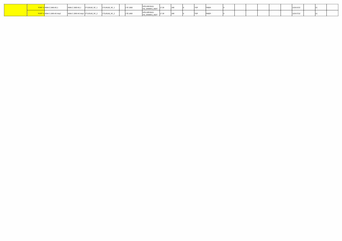
PORT 3 4566.C.1900.4G.1 4566.C.1900.4G.1 CTL05192_9C_1 CTL05192_9C_1 LTE 1900HPA-65R-BUU-
H8_1948MHz_06DT17.39 290 6 TOP FIBER 0 2233.5722 21
PORT 4 4566.C.1900.4G.tmp2 4566.C.1900.4G.tmp2 CTL05192_9C_2 CTL05192_9C_2 LTE 1900HPA-65R-BUU-
H8_1948MHz_06DT17.39 290 6 TOP FIBER 0 2233.5722 21

Diagram - Sector A Diagram File Name - CT5192_A_B_C_4T4R_v1.vsd
Atoll Site Name - CTV5192 Location Name -WINDSOR LOCKS
NORTHMarket - CONNECTICUT Market Cluster - NEW ENGLAND
Comments:
Decom
Antenna 1UMTS 850/1900
Broadband
Low700/850+45/-45
- +
Broadband
High
4Tx/4Rx+45/-45
- +
RET RET
DI PL EXER
8 50 1 90 0
DI PL EXER
8 50 1 90 0
GSM 1900
1 90 0
TX/RX
8 50 1 90 08 50
TX/RX
Antenna 2Antenna 3
LTE 700 BC / PCS
LTE RRUS-11700 (B/C)
TxA/RxA TxB/RxB
Da ta
Ou t
R xA
I/O
R xB
I/OR xA
Ou t
Da ta
InDC
BroadbandHEXLow
700/850+45/-45
- +
BroadbandHEXHigh
4Tx/4Rx+45/-45
- +
RET RET
BroadbandHEXHigh
4Tx/4Rx+45/-45
- +
RET
Fiber/DCDemarcation Box (Squid)
DC Plant
Antenna 4
MCU / CCUPDUBias-TBias-T
RXAIT
Du alDUP
Du alDUP
RM C
DUP DUP DUP DUP
T xR x T xR x T xR x T xR x T xR x T xR xT x T x T x T x
T xR x T xR x
TMA BP TMA BP
8 50 1 90 0 8 50 1 90 0
UMTS RBS
FUFU8 50
ANT A1 90 0
ANT A
8 50
ANT B
1 90 0
ANT B
T xA R xA 1 R xA 2 R xA 3 T xB R xB 1 R xB 2 R xB 3 T xA R xA 1 R xA 2 R xA 3 T xB R xB 1
RUT x R xA R xB
RUT x R xA R xB
2nd DUW1st DUW
R xB 2
LTE DUS 1 XMU
LTE RRUS-32 B2PCS
TxRx1 TxRx2
Da ta
Ou t
R xA I/
O
R xB I/
OR xA
Ou t
Da ta
InDC
TxRx3 TxRx4
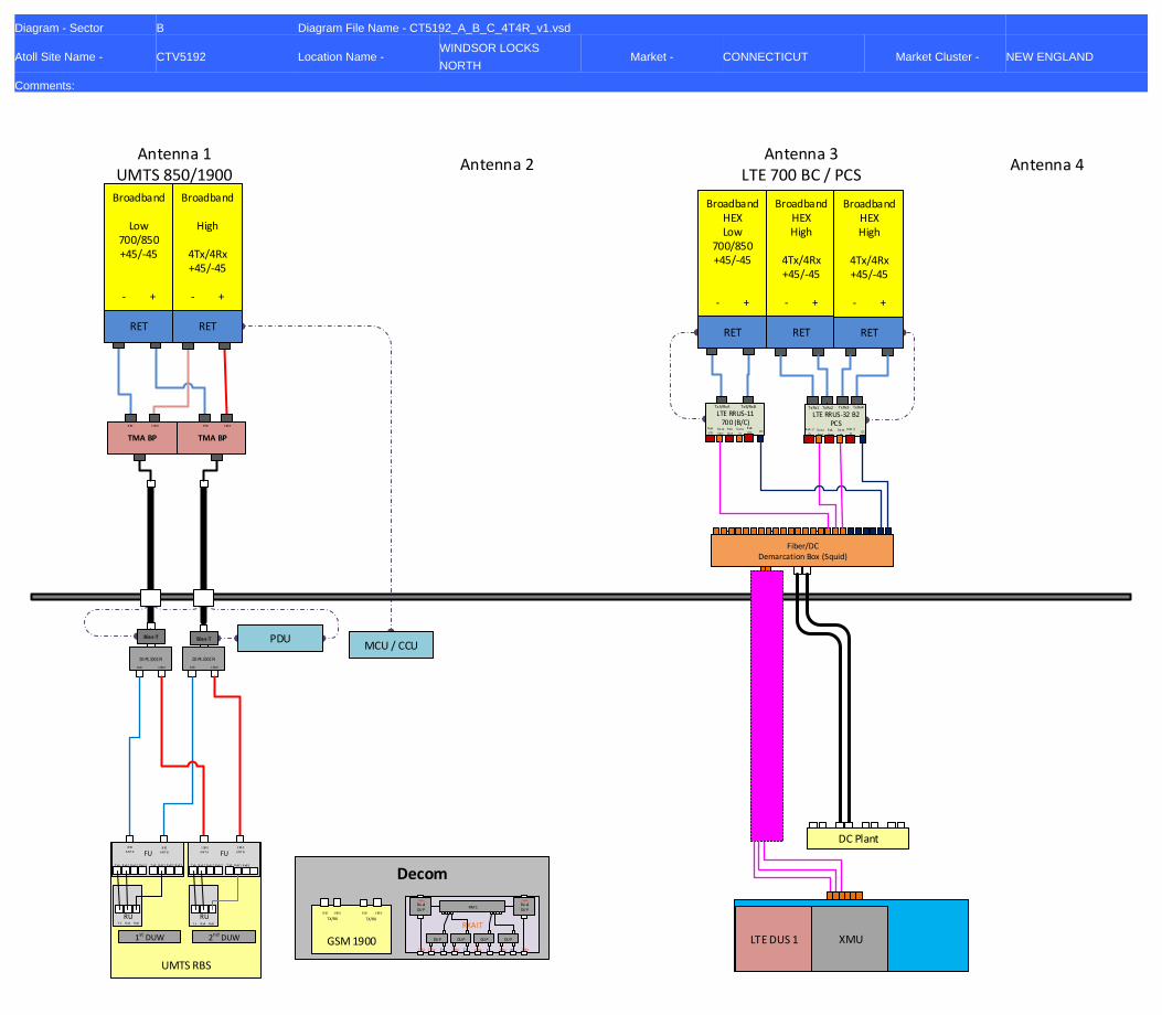
Diagram - Sector B Diagram File Name - CT5192_A_B_C_4T4R_v1.vsd
Atoll Site Name - CTV5192 Location Name -WINDSOR LOCKS
NORTHMarket - CONNECTICUT Market Cluster - NEW ENGLAND
Comments:
Decom
Antenna 1UMTS 850/1900
Broadband
Low700/850+45/-45
- +
Broadband
High
4Tx/4Rx+45/-45
- +
RET RET
DI PL EXER
8 50 1 90 0
DI PL EXER
8 50 1 90 0
GSM 1900
1 90 0
TX/RX
8 50 1 90 08 50
TX/RX
Antenna 2Antenna 3
LTE 700 BC / PCS
LTE RRUS-11700 (B/C)
TxA/RxA TxB/RxB
Da ta
Ou t
R xA
I/O
R xB
I/OR xA
Ou t
Da ta
InDC
BroadbandHEXLow
700/850+45/-45
- +
BroadbandHEXHigh
4Tx/4Rx+45/-45
- +
RET RET
BroadbandHEXHigh
4Tx/4Rx+45/-45
- +
RET
Fiber/DCDemarcation Box (Squid)
DC Plant
Antenna 4
MCU / CCUPDUBias-TBias-T
RXAIT
Du alDUP
Du alDUP
RM C
DUP DUP DUP DUP
T xR x T xR x T xR x T xR x T xR x T xR xT x T x T x T x
T xR x T xR x
TMA BP TMA BP
8 50 1 90 0 8 50 1 90 0
UMTS RBS
FUFU8 50
ANT A1 90 0
ANT A
8 50
ANT B
1 90 0
ANT B
T xA R xA 1 R xA 2 R xA 3 T xB R xB 1 R xB 2 R xB 3 T xA R xA 1 R xA 2 R xA 3 T xB R xB 1
RUT x R xA R xB
RUT x R xA R xB
2nd DUW1st DUW
R xB 2
LTE DUS 1 XMU
LTE RRUS-32 B2PCS
TxRx1 TxRx2
Da ta
Ou t
R xA I/
O
R xB I/
OR xA
Ou t
Da ta
InDC
TxRx3 TxRx4

Diagram - Sector C Diagram File Name - CT5192_A_B_C_4T4R_v1.vsd
Atoll Site Name - CTV5192 Location Name -WINDSOR LOCKS
NORTHMarket - CONNECTICUT Market Cluster - NEW ENGLAND
Comments:
Decom
Antenna 1UMTS 850/1900
Broadband
Low700/850+45/-45
- +
Broadband
High
4Tx/4Rx+45/-45
- +
RET RET
DI PL EXER
8 50 1 90 0
DI PL EXER
8 50 1 90 0
GSM 1900
1 90 0
TX/RX
8 50 1 90 08 50
TX/RX
Antenna 2Antenna 3
LTE 700 BC / PCS
LTE RRUS-11700 (B/C)
TxA/RxA TxB/RxB
Da ta
Ou t
R xA
I/O
R xB
I/OR xA
Ou t
Da ta
InDC
BroadbandHEXLow
700/850+45/-45
- +
BroadbandHEXHigh
4Tx/4Rx+45/-45
- +
RET RET
BroadbandHEXHigh
4Tx/4Rx+45/-45
- +
RET
Fiber/DCDemarcation Box (Squid)
DC Plant
Antenna 4
MCU / CCUPDUBias-TBias-T
RXAIT
Du alDUP
Du alDUP
RM C
DUP DUP DUP DUP
T xR x T xR x T xR x T xR x T xR x T xR xT x T x T x T x
T xR x T xR x
TMA BP TMA BP
8 50 1 90 0 8 50 1 90 0
UMTS RBS
FUFU8 50
ANT A1 90 0
ANT A
8 50
ANT B
1 90 0
ANT B
T xA R xA 1 R xA 2 R xA 3 T xB R xB 1 R xB 2 R xB 3 T xA R xA 1 R xA 2 R xA 3 T xB R xB 1
RUT x R xA R xB
RUT x R xA R xB
2nd DUW1st DUW
R xB 2
LTE DUS 1 XMU
LTE RRUS-32 B2PCS
TxRx1 TxRx2
Da ta
Ou t
R xA I/
O
R xB I/
OR xA
Ou t
Da ta
InDC
TxRx3 TxRx4

NOTES
Date Time (Central) Version ATTUID Note
3/13/2017 6:41:43 PM 1.00 mr673a RFDS/PD updated for 4T4R Retrofit job.
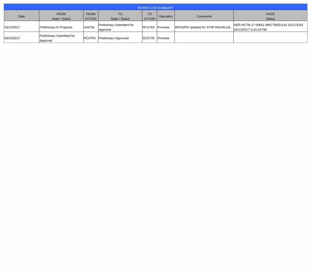
WORKFLOW SUMMARY
DateFROM
State / Status
FROM
ATTUID
TO
State / Status
TO
ATTUIDOperation Comments
PACE
Status
03/13/2017 Preliminary In Progress mr673aPreliminary Submitted for
ApprovalRC475S Promote RFDS/PD updated for 4T4R Retrofit job.
NER-RCTB-17-00651 MRCTB022142 SUCCESS
03/13/2017 6:43:18 PM
03/23/2017Preliminary Submitted for
ApprovalRC475S Preliminary Approved DC5778 Promote
Centerline Communications, LLC 95 Ryan Drive, Suite 1 Raynham MA 02767
Radio Frequency Emissions Analysis Report
AT&T Existing Facility
Site ID: CT5192
Windsor Locks North 104 Prospect Hill Road
East Windsor, CT 06088
December 18, 2017
Centerline Communications Project Number: 950006-086
Site Compliance Summary
Compliance Status: COMPLIANT
Site total MPE% of FCC general population
allowable limit: 27.22 %
Centerline Communications, LLC 95 Ryan Drive, Suite 1 Raynham MA 02767
December 18, 2017
AT&T Mobility – New England Attn: John Benedetto, RF Manager 550 Cochituate Road Suite 550 – 13&14 Framingham, MA 06040
Emissions Analysis for Site: CT5192 – Windsor Locks North
Centerline Communications, LLC (“Centerline”) was directed to analyze the proposed AT&T facility located at 104 Prospect Hill Road, East Windsor, CT, for the purpose of determining whether the emissions from the Proposed AT&T Antenna Installation located on this property are within specified federal limits.
All information used in this report was analyzed as a percentage of current Maximum Permissible Exposure (% MPE) as listed in the FCC OET Bulletin 65 Edition 97-01and ANSI/IEEE Std C95.1. The FCC regulates Maximum Permissible Exposure in units of microwatts per square centimeter (W/cm2). The number of W/cm2 calculated at each sample point is called the power density. The exposure limit for power density varies depending upon the frequencies being utilized. Wireless Carriers and Paging Services use different frequency bands each with different exposure limits, therefore it is necessary to report results and limits in terms of percent MPE rather than power density.
All results were compared to the FCC (Federal Communications Commission) radio frequency exposure rules, 47 CFR 1.1307(b)(1) – (b)(3), to determine compliance with the Maximum Permissible Exposure (MPE) limits for General Population/Uncontrolled environments as defined below.
General population/uncontrolled exposure limits apply to situations in which the general population may be exposed or in which persons who are exposed as a consequence of their employment may not be made fully aware of the potential for exposure or cannot exercise control over their exposure. Therefore, members of the general population would always be considered under this category when exposure is not employment related, for example, in the case of a telecommunications tower that exposes persons in a nearby residential area.
Population exposure to radio frequencies is regulated and enforced in units of microwatts per square centimeter (μW/cm2). The general population exposure limits for the 700 and 850 MHz Bands are approximately 467 μW/cm2 and 567 μW/cm2 respectively. The general population exposure limit for the 1900 MHz (PCS), 2100 MHz (AWS) and 2300 MHz (WCS) bands is 1000 μW/cm2. Because each carrier will be using different frequency bands, and each frequency band has different exposure limits, it is necessary to report percent of MPE rather than power density.
Centerline Communications, LLC 95 Ryan Drive, Suite 1 Raynham MA 02767
Occupational/controlled exposure limits apply to situations in which persons are exposed as a consequence of their employment and in which those persons who are exposed have been made fully aware of the potential for exposure and can exercise control over their exposure. Occupational/controlled exposure limits also apply where exposure is of a transient nature as a result of incidental passage through a location where exposure levels may be above general population/uncontrolled limits (see below), as long as the exposed person has been made fully aware of the potential for exposure and can exercise control over his or her exposure by leaving the area or by some other appropriate means.
Additional details can be found in FCC OET 65.
Centerline Communications, LLC 95 Ryan Drive, Suite 1 Raynham MA 02767
CALCULATIONS
Calculations were performed for the proposed AT&T Wireless antenna facility located at 104 Prospect
Hill Road, East Windsor, CT, using the equipment information listed below. All calculations were performed per the specifications under FCC OET 65. Since AT&T is proposing highly focused directional panel antennas, which project most of the emitted energy out toward the horizon, all calculations were performed assuming a lobe representing the maximum gain of the antenna per the antenna manufactures supplied specifications, minus 10 dB, was focused at the base of the tower. For this report the sample point is the top of a 6-foot person standing at the base of the tower.
Per FCC OET Bulletin No. 65 - Edition 97-01 recommendations to achieve the maximum anticipated value at each sample point, all power levels emitting from the proposed antenna installation are increased by a factor of 2.56 to account for possible in-phase reflections from the surrounding environment. All power values expressed and analyzed are maximum power levels expected to be used on all radios.
All emissions values for additional carriers were taken from the Connecticut Siting Council (CSC) active MPE database. Values in this database are provided by the individual carriers themselves. For this site, there were no additional carriers listed in the CSC active MPE database. Sprint and Verizon Wireless are currently active at this facility. For this analysis, calculations were performed on these existing carriers based upon known configurations in this area to approximate their contributions.
For each sector the following channel counts, frequency bands and power levels were utilized as shown in Table 1:
Technology Frequency Band Channel Count Transmit Power per
Channel (W) UMTS 850 MHz 2 30 UMTS 1900 MHz (PCS) 2 30 LTE 700 MHz 2 60 LTE 1900 MHz (PCS) 4 60
Table 1: Channel Data Table
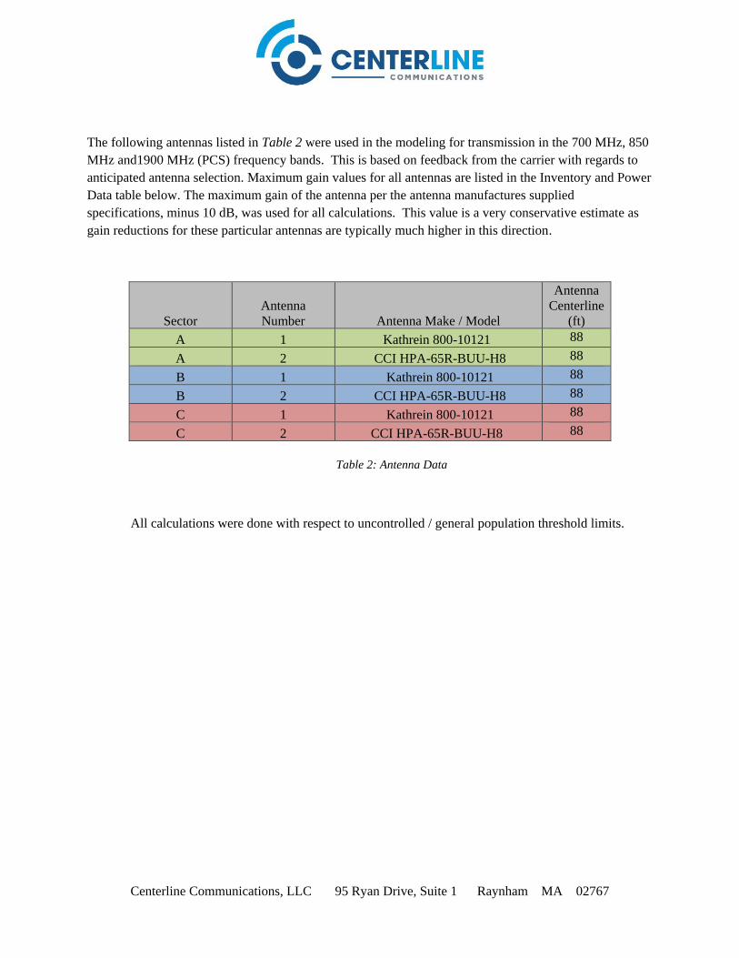
Centerline Communications, LLC 95 Ryan Drive, Suite 1 Raynham MA 02767
The following antennas listed in Table 2 were used in the modeling for transmission in the 700 MHz, 850 MHz and1900 MHz (PCS) frequency bands. This is based on feedback from the carrier with regards to anticipated antenna selection. Maximum gain values for all antennas are listed in the Inventory and Power Data table below. The maximum gain of the antenna per the antenna manufactures supplied specifications, minus 10 dB, was used for all calculations. This value is a very conservative estimate as gain reductions for these particular antennas are typically much higher in this direction.
Sector Antenna Number Antenna Make / Model
Antenna Centerline
(ft) A 1 Kathrein 800-10121 88 A 2 CCI HPA-65R-BUU-H8 88 B 1 Kathrein 800-10121 88 B 2 CCI HPA-65R-BUU-H8 88 C 1 Kathrein 800-10121 88 C 2 CCI HPA-65R-BUU-H8 88
Table 2: Antenna Data
All calculations were done with respect to uncontrolled / general population threshold limits.
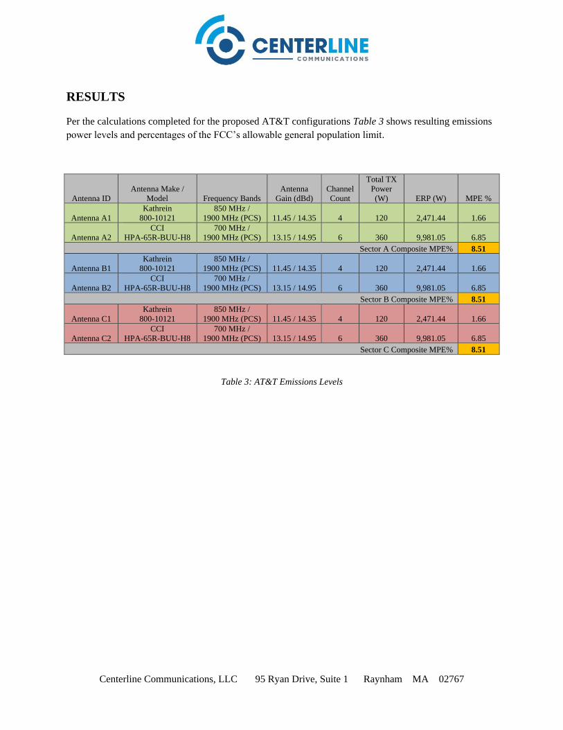
Centerline Communications, LLC 95 Ryan Drive, Suite 1 Raynham MA 02767
RESULTS
Per the calculations completed for the proposed AT&T configurations Table 3 shows resulting emissions power levels and percentages of the FCC’s allowable general population limit.
Antenna ID Antenna Make /
Model Frequency Bands Antenna
Gain (dBd) Channel Count
Total TX Power (W) ERP (W) MPE %
Antenna A1 Kathrein
800-10121 850 MHz /
1900 MHz (PCS) 11.45 / 14.35 4 120 2,471.44 1.66
Antenna A2 CCI
HPA-65R-BUU-H8 700 MHz /
1900 MHz (PCS) 13.15 / 14.95 6 360 9,981.05 6.85 Sector A Composite MPE% 8.51
Antenna B1 Kathrein
800-10121 850 MHz /
1900 MHz (PCS) 11.45 / 14.35 4 120 2,471.44 1.66
Antenna B2 CCI
HPA-65R-BUU-H8 700 MHz /
1900 MHz (PCS) 13.15 / 14.95 6 360 9,981.05 6.85 Sector B Composite MPE% 8.51
Antenna C1 Kathrein
800-10121 850 MHz /
1900 MHz (PCS) 11.45 / 14.35 4 120 2,471.44 1.66
Antenna C2 CCI
HPA-65R-BUU-H8 700 MHz /
1900 MHz (PCS) 13.15 / 14.95 6 360 9,981.05 6.85 Sector C Composite MPE% 8.51
Table 3: AT&T Emissions Levels
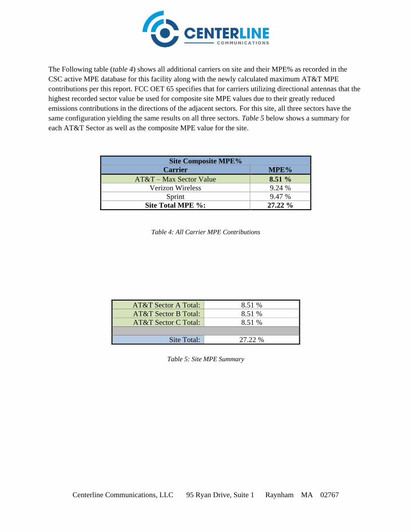
Centerline Communications, LLC 95 Ryan Drive, Suite 1 Raynham MA 02767
The Following table (table 4) shows all additional carriers on site and their MPE% as recorded in the CSC active MPE database for this facility along with the newly calculated maximum AT&T MPE contributions per this report. FCC OET 65 specifies that for carriers utilizing directional antennas that the highest recorded sector value be used for composite site MPE values due to their greatly reduced emissions contributions in the directions of the adjacent sectors. For this site, all three sectors have the same configuration yielding the same results on all three sectors. Table 5 below shows a summary for each AT&T Sector as well as the composite MPE value for the site.
Table 4: All Carrier MPE Contributions
Table 5: Site MPE Summary
Site Composite MPE%
Carrier MPE%
AT&T – Max Sector Value 8.51 %
Verizon Wireless 9.24 % Sprint 9.47 %
Site Total MPE %: 27.22 %
AT&T Sector A Total: 8.51 % AT&T Sector B Total: 8.51 % AT&T Sector C Total: 8.51 %
Site Total: 27.22 %
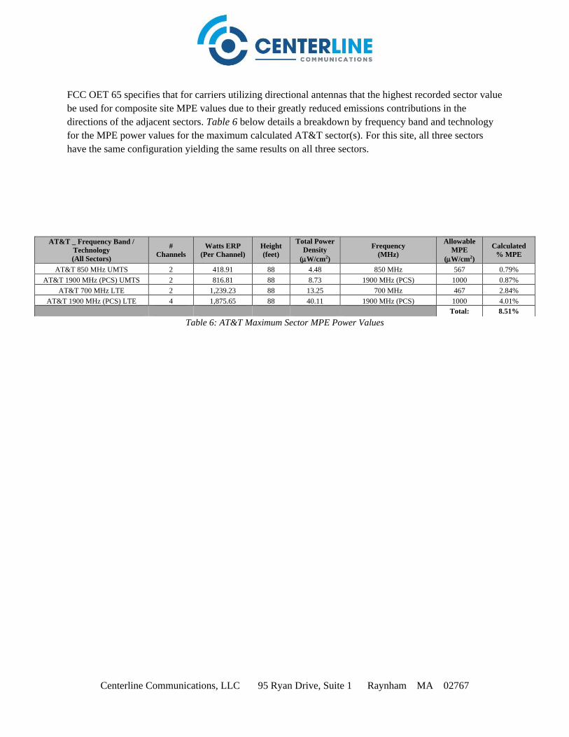
Centerline Communications, LLC 95 Ryan Drive, Suite 1 Raynham MA 02767
FCC OET 65 specifies that for carriers utilizing directional antennas that the highest recorded sector value be used for composite site MPE values due to their greatly reduced emissions contributions in the directions of the adjacent sectors. Table 6 below details a breakdown by frequency band and technology for the MPE power values for the maximum calculated AT&T sector(s). For this site, all three sectors have the same configuration yielding the same results on all three sectors.
Table 6: AT&T Maximum Sector MPE Power Values
AT&T _ Frequency Band /
Technology
(All Sectors)
#
Channels
Watts ERP
(Per Channel)
Height
(feet)
Total Power
Density
(W/cm2)
Frequency
(MHz)
Allowable
MPE
(W/cm2)
Calculated
% MPE
AT&T 850 MHz UMTS 2 418.91 88 4.48 850 MHz 567 0.79% AT&T 1900 MHz (PCS) UMTS 2 816.81 88 8.73 1900 MHz (PCS) 1000 0.87%
AT&T 700 MHz LTE 2 1,239.23 88 13.25 700 MHz 467 2.84% AT&T 1900 MHz (PCS) LTE 4 1,875.65 88 40.11 1900 MHz (PCS) 1000 4.01%
Total: 8.51%
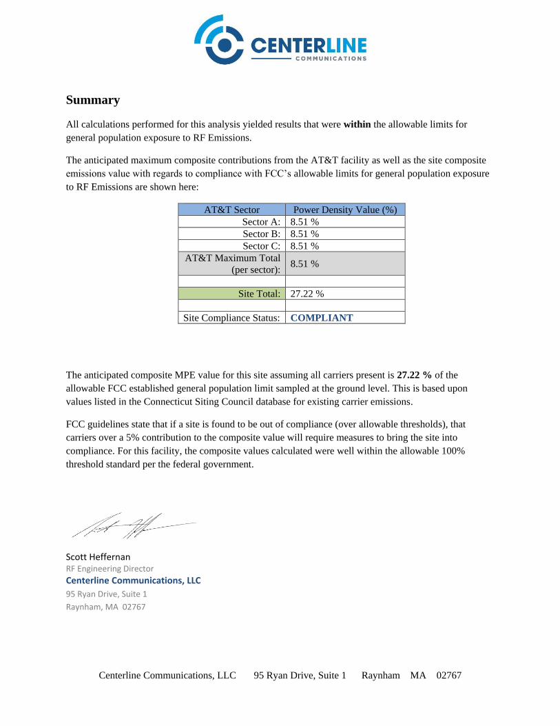
Centerline Communications, LLC 95 Ryan Drive, Suite 1 Raynham MA 02767
Summary
All calculations performed for this analysis yielded results that were within the allowable limits for general population exposure to RF Emissions.
The anticipated maximum composite contributions from the AT&T facility as well as the site composite emissions value with regards to compliance with FCC’s allowable limits for general population exposure to RF Emissions are shown here:
AT&T Sector Power Density Value (%) Sector A: 8.51 % Sector B: 8.51 % Sector C: 8.51 %
AT&T Maximum Total (per sector): 8.51 %
Site Total: 27.22 %
Site Compliance Status: COMPLIANT
The anticipated composite MPE value for this site assuming all carriers present is 27.22 % of the allowable FCC established general population limit sampled at the ground level. This is based upon values listed in the Connecticut Siting Council database for existing carrier emissions.
FCC guidelines state that if a site is found to be out of compliance (over allowable thresholds), that carriers over a 5% contribution to the composite value will require measures to bring the site into compliance. For this facility, the composite values calculated were well within the allowable 100% threshold standard per the federal government.
Scott Heffernan RF Engineering Director
Centerline Communications, LLC
95 Ryan Drive, Suite 1
Raynham, MA 02767