Embed Size (px)
Citation preview

December 9, 2014
CALL NO. 315
CONTRACT ID NO. 141299
ADDENDUM # 1
Subject: Campbell County, FD04 019 0008 CUL EXT
Letting December 12, 2014
(1)Revised – Plan Sheets – S1, S2, S3, S4, S5, S13, S14A, S15, S18, & S23
(2)Revised – Bid Items - Pages 72-73 of 73
(3)Added - Special Notes – Pages 1-17 of 17
Proposal revisions are available at http://transportation.ky.gov/Construction-
Procurement/.
Plan revisions are available at http://www.lynnimaging.com/kytransportation/.
If you have any questions, please contact us at 502-564-3500.
Sincerely,
Diana Castle Radcliffe
Director
Division of Construction Procurement
DR:ks
Enclosures

CO
NS
TR
UC
TIO
N
PR
OJ
EC
T
NO.
LE
TTIN
G
DA
TE
TRANSPORTATION CABINETDEPARTMENT OF HIGHWAYS
INDEX OF SHEETSSheet No. Description
SPECIAL NOTES
S1
S2
SPECIAL PROVISIONS
ROADWAY STANDARD DRAWINGS
SPECIFICATIONS
Current Interims.
2010 AASHTO LRFD Bridge Design Specifications with
TAYLOR CREEK CULVERT EXTENSION
RIVERBOAT ROW
CAMPBELL COUNTY
S1
TITLE SHEET
S6
S7
S8
S9
PROJECT AREA
General Notes
Miscellaneous Details
Site Plan
Title Sheet
LAYOUT MAP
NITRAM NIVEK ,EZLOK MAP ,ENOTS KCIRTAP ,HTIMS XELA
Construction.
2012 Standard Specifications for Road and Bridge
J. Ramler D. Wormald
J. Wanstrath J. Ramler
Cross Sections
S3-S5
Temporary Shoring
Culvert Profile
X1-X12
Grading Plan
Coordinate Control
S12
S25
STRUCTURE STANDARD DRAWINGS
Manhole Type B
Stencils for StructuresBGX-006-08
RGX-010-03 Typical Embankment Foundation Benches
Miscellaneous Standards Part 1RGX-001-05
RDX-300-03 Precast Box Culvert Extension
Silt Trap Type ARDX-220-04
RDX-230
RDX-210-02 Temporary Silt Fence
RDM-100-02 Frame and Lid Type 1
RDI-120-03
RDM-005-05
RDB-430-04 Manhole Steps
RDB-003-07 Drop Box Inlet Type 3
Subsurface DataS10-S11
S16-S18
Bedding for Precast Box Culverts, Sewers, Storm Drains, and their Combinations
BPS-011-03 HP14x89 Steel Pile (See Foundation Notes)
S23 Closure Diaphragm
Decorative Fence
Silt Trap Type C
Type B Armor Rock
RGX-015-02 Settlement Platform
S27208_001.
dgn
Estimate of Quantities
Foundation LayoutS13
Combination Pile Wall
Sewer Support System
S15 Pile Notes
Culvert FoundationS19-S22
S24 Combination Pile Wall Cap
Pipe Drainage Profile
S26-S28
Bill of ReinforcementS29
27019
ST
AT
E
OF KENT
UC
KY
PR
OFE
SSIONAL
EN
GIN
EE
R
LICENSED
BAKER
TRAVIS M.
19646
ST
AT
E
OF KENT
UC
KY
PR
OFE
SSIONAL
EN
GIN
EE
R
LICENSED
STRUCTURE COMPONENTS
WORMALD
DAVID L.
SITE LAYOUT
E-S
HE
ET
NA
ME:
Micro
Statio
n v8.11.9.397
ITEM NUMBER
DRAWING NO.
SHEET NO.
Commonwealth of Kentucky
DEPARTMENT OF HIGHWAYSCOUNTY
ROUTE CROSSING
PREPARED BY
DETAILED BY:
DESIGNED BY:
DATE: CHECKED BY
REVISION DATE
06-8703
CAMPBELL
TAYLOR CREEK CULVERT
www.urscorp.comCincinnati, OH 45202525 Vine Street, Suite 1800URS Corporation
FIL
E
NA
ME:
11/17/2014
27208
S14-S14A
November 17, 2014
November 17, 2014
DA
TE P
LO
TT
ED:
No
v. 17 2014
jo
n_
wanstrath
US
ER:
Vibration Monitoring
Dynamic Pile Testing

S2
ESTIMATE OF QUANTITIES
GENERAL SUMMARY
SH
EET
NO.
SKEW
UNIT TO BID
ITEM CODE
REMARKS
TOTAL PROJECT
PIPE DRAINAGE SUMMARY
24 IN
CH
PIP
E
ST
OR
M
SE
WE
R
TY
PE
A
MA
NH
OL
E
TY
PE
B
MA
NH
OL
E
TY
PE 3
IN
LE
T
DR
OP
BO
X
RE
MO
VE PIP
E
1310 1756
TO
TO
31
STA 1+81.20 LT
STA 1+78.00 LT
STA 2+11.30 LT
STA 1+84.00 RT
1
1
LIN FT LIN FT EACH
1
81 1 1114
14
50
CONST. ABOVE 3-SIDED CULVERT
1496 1761524
J. Ramler D. Wormald
J. RamlerJ. Wanstrath
1792
1
1
MA
NH
OL
E
ADJ
US
T
STA 1+13.60 LT
CRUSHED AGGREGATE SIZE NO. 57
* INCLUDES STRUCTURE GRANULAR BACKFILL AND
Earthwork Quantities
Emb*
Com Exc
13448 (CUYD)
386 (CUYD)
=
=
S27208_002.dgn
E-S
HE
ET
NA
ME:
Micro
Statio
n v8.11.9.397
ITEM NUMBER
DRAWING NO.
SHEET NO.
Commonwealth of Kentucky
DEPARTMENT OF HIGHWAYSCOUNTY
ROUTE CROSSING
PREPARED BY
DETAILED BY:
DESIGNED BY:
DATE: CHECKED BY
REVISION DATE
06-8703
CAMPBELL
TAYLOR CREEK CULVERT
www.urscorp.comCincinnati, OH 45202525 Vine Street, Suite 1800URS Corporation
FIL
E
NA
ME:
11/17/2014
27208
DA
TE P
LO
TT
ED:
No
v. 17 2014
jo
n_
wanstrath
US
ER:
ITEM DESCRIPTION UNIT
QU
AN
TIT
Y
71 CRUSHED AGGREGATE SIZE NO. 57 TON 4539
2230 EMBANKMENT IN PLACE CUYD 5937
2231 STRUCTURE GRANULAR BACKFILL CUYD 5617
2545 CLEARING AND GRUBBING LS 1
2568 MOBILIZATION LS 1
2569 DEMOBILIZATION LS 1
2650 MAINTAIN & CONTROL TRAFFIC LS 1
2726 STAKING LS 1
2731 REMOVE STRUCTURE LS 1
2998 MASONRY COATING SQYD 165
5985 SEEDING AND PROTECTION SQYD 3304
8003 FOUNDATION PREPARATION LS 1
8019 CYCLOPEAN STONE RIPRAP TON 194
8033 TEST PILES LF 376
8039 PRE DRILLING FOR PILES LF 390
8052 PILES HP 14X117 LF 7029
8095 PILE POINTS-14 IN EACH 78
8100 CONCRETE-CLASS A CUYD 358
8106 CONCRETE-CLASS M 1 CUYD 104
8150 STEEL REINFORCEMENT LB 53000
8551 MACHINE PREP OF SLAB SQYD 356
21804EN 3-SIDED CULVERT LF 133
23143ED KPDES PERMIT AND TEMP EROSION CONTROL LS 1
23233EC DYNAMIC PILE TESTING EACH 4
23315EC DECORATIVE FENCE LF 202
24246EC REMOVE ABANDONED SANITARY SEWER LF 40
24423EC TEMPORARY SHORING LS 1
24630EC TYPE B ARMOR ROCK TON 351
24754ED SETTLEMENT MONITORING LS 1
24756EC COMBINATION PILE WALL SQFT 11309
24757EC COMBINATION PILE WALL STRUCTURAL STEEL LS 1
24758EC SEWER SUPPORT SYSTEM LS 1
24759EC PUMPED GROUT CF 100
24761EC CLOSURE DIAPHRAGM LS 1

S3
J. Ramler D. Wormald
A. Dykes J. Ramler
GENERAL SPECIFICATION NOTES
GENERAL NOTES
SEQUENCE OF CONSTRUCTIONMATERIAL SPECIFICATION NOTES
SEQUENCE OF CONSTRUCTION (CONTINUED)
S27208_003.dgn
GENERAL NOTES (1)
E-S
HE
ET
NA
ME:
Micro
Statio
n v8.11.9.397
ITEM NUMBER
DRAWING NO.
SHEET NO.
Commonwealth of Kentucky
DEPARTMENT OF HIGHWAYSCOUNTY
ROUTE CROSSING
PREPARED BY
DETAILED BY:
DESIGNED BY:
DATE: CHECKED BY
REVISION DATE
06-8703
CAMPBELL
TAYLOR CREEK CULVERT
www.urscorp.comCincinnati, OH 45202525 Vine Street, Suite 1800URS Corporation
FIL
E
NA
ME:
11/17/2014
27208
completed work will be repaired at the contractor's expense.
damages do occur to in-place work, the district bridge engineer shall be notified of such damages. All damages to
damaged, rendered unsuitable, altered, discolored, and impaired during the course of the construction project. If
DAMAGE TO COMPLETED WORK: The contractor shall ensure that in-place construction work and improvements are not
Trinity Industries will not be permitted as an option for bid item "Guardrail End Treatment Type 1".
GUARDRAIL: Contrary to KYTC Standard Drawing RBR-020-05 the guardrail end treatment ET-Plus manufactured by
Sewer.
information only. The contractor shall field verify existing locations, dimension and materials for the Sanitary
available from the Kentucky Transportation Cabinet District 6 at (859) 341-2700. These drawings are for provided for
Project drawings for the existing Sanitation District No. 1 Sanitary Sewer are EXISTING SANITARY SEWER DRAWINGS:
District 6 at (859) 341-2700.
The project specific geotechnical report is available from the Kentucky Transportation Cabinet GEOTECHNICAL REPORT:
to utilities caused by the Contractor shall be repaired at his own expense.
UTILITY PROTECTION: Any active utility ducts including the sanitary sewer, shall be adequately protected. Any damage
to complete the structure.
removing all or parts of existing structures, phase construction, incidental materials, labor or anything else required
bid item most appropriate to the work involved. This may include cofferdams, shoring, excavations, backfilling,
and specifications. Material, labor or construction operations, not otherwise specified, are to be included in the
COMPLETION OF THE STRUCTURE: The Contractor is required to complete the structure in accordance with the plans
dimensions.
DIMENSIONS: Dimensions are for a normal temperature of 60 degrees Fahrenheit. Layout dimensions are horizontal
SLOPE PROTECTION: Use dry cyclopean stone rip rap in accordance with the plans and specifications.
bid for remove structure.
to a depth of one inch to facilitate a neat line. The cost of cutting concrete shall be included in the unit price
SAWCUTTING EXISTING CONCRETE: Prior to the removal of the existing concrete, cut the surface with a concrete saw
fabrication.
by the engineer prior to the final approval of the shop drawings and welding procedure and the start of the
WELDING PROCEDURE: Qualification tests of all welding procedures shall be completed by the contractor and approved
written consent of the designer, and then only in the manner and at the locations designated in the authorization.
PROHIBITED FIELD WELDING: Except as shown on the plans, no welding of any nature shall be performed without the
while work is proceeding below the flow line elevation of the Ohio River at any given time.
Raising of the bottom of footings is not allowed. It is anticipated that dewatering activities may be necessary
FOOTING EXCAVATION: Ensure excavation for footings is in accordance with subsection 603.03.03 of the specifications.
PILE PROTECTION: Provide pile protection in accordance with subsection 604.03.11 of the standard specifications.
the specifications and of the type as shown on the pile notes.
PILE POINTS: Provide pile points for all point bearing piles. Ensure pile points are in accordance with section 604 of
or labor, not otherwise specified, are to be considered incidental to the contract.
INCIDENTAL MATERIALS: The structure is to be completed in accordance with the plans and specifications. Materials
BEVELED EDGES: Bevel all exposed edges ‡", unless otherwise noted.
stirrup bend diameters for bars designated by suffix (s) in a bill of reinforcement.
noted. Epoxy coat bars designated by suffix (e) in accordance with section 811.10 of the standard specifications. Use
Spacing of bars is from center to center of bars. Clear distance to face of concrete is 2", unless otherwise
REINFORCEMENT: Dimensions shown from the face of concrete to bars are to center of bars unless otherwise shown.
in the current LRFD Specifications.
DESIGN METHOD: All reinforced concrete members are designed by the load and resistance factor method as specified
CULVERT DESIGN LOAD: HL-93 Live Load with fill as shown on Culvert Profile at 126 pcf.
All references to the AASHTO Specifications are to the AASHTO LRFD Bridge Design Specifications, 5th Edition.
Highways Standard Specifications for Road and Bridge Construction including any current Supplemental Specifications.
SPECIFICATIONS: References to the specifications are to the current edition of the Kentucky Department of
Restore all disturbed areas and place permanent seeding, etc.f)
Install decorative fencing.e)
following placement of backfill in Step 11 or as directed by Engineer and backfill to grade.
Pump grout under existing culvert slab, construct cast-in-place concrete cap a minimum of one weekd)
Place permanent erosion control (protection Cyclopean riprap and Type B Armor Rock).c)
Remove temporary shoring as necessary along Riverboat Row.b)
Cast closure pours between the combination pile wall and precast culvert headwall segment.a)
12. Complete Final Activities
clay cap. Extend settlement platforms to final grade.
or soils surrounding and backfill granular structural between fabric Geotextile III Type Place plans. the in shown
as backfill granular structural use shall zone rod anchor within and Wall, Pile Combination behind Backfill plans.
the in shown as grade final to walls anchor and rods, threaded Wall Pile Combination culvert, around backfill Place
11. Backfill to Final Grade
of settlement platforms.
monitoring Continue notes. and details Wall Pile Combination the to according conduit rigid protective the in rods
threaded and wales the install driven, are walls anchor the Once sections. cross the in shown as backfill granular
structure including 461.0 El. to Backfill plans. the in shown limits the to Wall Pile Combination of driving Complete
10. Install Combination Pile Wall Threaded Rods and Anchor Walls
line performed during Step 7.
flow culvert existing the to modification with pour closure Coordinate sections. culvert precast new and culvert
precast existing the between plans the in shown as diaphragm closure culvert the cast and bars dowel Install
9. Cast Culvert Closure Diaphragm
manufacturer's recommendations. Construct 24" storm pipe connected to culvert.
with accordance in waterproofing and restraints lateral segments, between connections external Install
manhole. access the Install directions. manufacturer's the with accordance in segments culvert precast the Place
8. Place Precast Culvert Segments
construction of culvert foundation.
following plans, the in shown as flowline, culvert existing the Regrade location. slab new the to directed
be can discharge the completed been have walls and slab base the Once construction. foundation the during
maintained be must Creek Taylor from Discharge monitoring. begin and plans the in shown as platforms settlement
backfill Place constructed. be can walls and slab foundation culvert cast-in-place the 458.5, El. to up placed
been has backfill the and installed, been have piles culvert the place, in is system support sewer the Once
7. Construct Culvert Foundation
installed during Step 4.
not if piles culvert Install slab. culvert of bottom to backfill System, Support Sewer the of installation Following
6. Backfill to Construct Culvert Foundation
more information on installing the sewer support and monitoring requirements.
for drawings support sewer the See 2'). (+/- 452.0 El. above placed is backfill before cut piles sewer existing
and place in be must System Support Sewer the 4, Step in described procedures installation pile the of any For
5. Install Sewer Support System
foundation (see Step 6) before installing the culvert piles.
culvert the construct to backfill and 5), Step (see support sewer piles, sewer the install to be could approach
alternate An simultaneously. piles culvert and piles sewer the install to choose may Contractor the construction,
of ease For System. Support Sewer the and foundations slab culvert the both for piles bearing Drive
4. Drive H Piles for Culvert and Sewer Support System
requirements.
monitoring and support sewer the installing on information more for drawings support sewer the See support.
sewer of construction and driving pile for preparation in sewer existing of portions buried expose to needed as
Excavate support. sewer sanitary new the construct to platform work a for 2') (+/- 452.0 El. to fill aggregate
with areas surrounding and pool plunge existing the fill Wall, Pile Combination the of installation Following
3. Backfill to Construct Sewer Support
plans.
the in shown as piles pipe Wall Pile Combination the Fill engineer. the from authorization without permitted not is
sewer sanitary aerial existing the above equipment staging for fill Temporary construction. during maintained be
shall Creek Taylor from discharge of Diversion pool. plunge the of dewatering and filling for provide to minimum,
a at LT), 45+00 Sta to RT 35+00 Sta. (approx pool plunge existing the of limits the to wall pile combination
the driving with proceed and necessary as pool plunge the from obstructions remove established, is access Once
Pile Wall to provide access for equipment.
Combination the of vicinity the in fill aggregate temporary place to necessary be may It permit. DA project the
with accordance in be shall River Ohio the from material of disposal and Excavation required. equipment the on
depending necessary be may dredging some used, is barge work a If River. Ohio the from barge work a with or
restaurant House Chart the to adjacent drive gravel the via site the access wall, pile combination the drive To
2. Drive Combination Pile Wall
constructed in coordination with the shoring and backfilling operations.
be may culvert the of east located sewer storm 24" the of Portions notes. general the with accordance
in maintained be will Row Riverboat on Traffic installation. pile permit to 4 Step to prior time any or time this
at shown limits the to removed be can sewer sanitary abandoned and wall wing culvert, existing the of Portions
plans. the in shown limits the to backfill and Row Riverboat to adjacent shoring temporary Install requirements.
permit water storm construction project the with accordance in measures control erosion temporary
Place note. special per stystem monitoring vibration Install debris. remove as well as limits construction
the within vegetation existing remove to site the grub and clear areas, adjacent and Row Riverboat Utilizing
1. Clear and Grub Site - Install Temporary Shoring
discretion.
Contractor's the at are step each in described methods and means The Engineer. the from granted is writing
in permission unless construction of sequence following the using project the construct to is Contractor The
See sheet S15 for additional information for pile materials.
Class "A" Concrete (All Other Locations) - See Section 601. f'c = 3500 psi
"M2".
Class "M" Concrete (Culvert Regrading) - See Section 601. Use either "M1" or
furnished:
for Road and Bridge Construction shall govern the following materials
MATERIALS: The Kentucky Department of Highways Standard Specifications
Steel Reinforcing: Fy = 60000 psi
DESIGN STRESSES:
DA
TE P
LO
TT
ED:
No
v. 17 2014
jo
n_
wanstrath
US
ER:

BEFORE YOU DIG
utility companies have facilities in the area. may be necessary for the contractor to contact the County Court Clerk to determine what excavation with the utility owners, including those whom do not subscribe to KY 811. It members of the KY 811 one-call Before-U-Dig (BUD) service. The contractor must coordinate contractor should be aware that owners of underground facilities are not required to be a minimum of two (2) and no more than ten (10) business days prior to excavation. The for information on the location of existing underground utilities. The call is to be placed The contractor is instructed to call 1-800-752-6007 to reach KY 811, the one-call system
MAINTENANCE OF TRAFFIC
UTILITY OWNERSHIP
J. Ramler
A. Dykes
D. Wormald
J. Ramler
S4
BACKFILL
REMOVE STRUCTURE
GENERAL NOTES
20' Span X 10' Rise Flow Area 185 Sq Ft
20' Span X 10' Rise Flow Area 185 Sq Ft
20' Span X 10' Rise Flow Area 185 Sq Ft
20' Span X 10' Rise Flow Area 185 Sq Ft
CULVERT NOTES
CONTRACT SEAN BLAKE, STORM WATER DEPARTMENT, SANITATION DISTRICT NO. 1 AT 859-578-7468.
CONTRACTOR IS RESPONSIBLE FOR OBTAINING GRADING PERMIT FROM SANITATION DISTRICT NO. 1.
CONTACT & PHONE #
SANITATION DISTRICT NO. 1:
CONTACT & PHONE #
NORTHERN KENTUCKY WATER DISTRICT:
CONTACT & PHONE #
DUKE ENERGY: GAS
CONTACT & PHONE #
DUKE ENERGY: ELECTRIC
CONTACT & PHONE #
CINCINNATI BELL:
granular backfill shall be considered incidental to embankment in place.
The select granular backfill shall be paid for as Structure Granular Backfill. The two foot clayey cap over the select
combination pile wall and anchorages.
appropriate equipment and methods to compact the fill and backfill without damaging the precast culvert or
reduce infiltration and the buildup of hydrostatic pressures on the culvert and walls. The Contractor shall select
backfill for the culvert and combination pile wall shall be capped with at least two feet of compacted clayey soils to
percent relative density (ASTM D4253 and D4254), whichever results in a greater dry density. The select granular
shall be compacted to at least 95 percent of the Standard Proctor Maximum Dry Density (AASHTO T99) or at least 80
Construction, the precast concrete culvert manufacturer's specifications and the following requirements. The backfill
the backfill should be performed in accordance with the current Kentucky Standard Specifications for Road and Bridge
No. 200 sieve should be restricted to a maximum of three percent. The backfill materials, placement and compaction of
granular backfill shall consist of free-draining soils classified into AASHTO Group A-1, except that the percent passing
anchor wall shall be select granular backfill as shown in the plans followed by compacted clayey backfill. The select
The backfill around the extended culvert and behind the proposed combination pile wall, anchor rods and sheet pile
removed completely. The intact headwall shall be removed to at least the limits shown in the plans.
3-sided culvert, stem walls, floor and reinforced concrete liner as detailed in the plans. The detached headwall shall be
This item shall include removal of the existing culvert headwalls, headwall foundation and a 16 foot length of the existing
of this material.
archival purposes. This information will be submitted to the division of construction. Allow 4 weeks time for review
and Bridge Construction should be supplied as well. Include one set of structural design calculations for review and
project. Backfill requirements and any specifications that are contrary to the KYTC Standard Specifications for Road
10. The manufacturer or supplier must provide 6 copies of detailed shop drawings for final approval for use on this
engineer. See plans for backfill requirements.
signed by the contractor and the manufacturer of the 3-sided structure and will be submitted to the resident
Construction will require a certification letter stating that the backfill was constructed properly. The letter will be
9. 3-sided structures that require special backfill contrary to KYTC Standard Specifications for Road and Bridge
required for these structures. See plans for details.
8. In accordance with section 615 of KYTC Standard Specifications for Road and Bridge Construction, weep holes will be
7. Comply with section 106.04 of the Standard Specifications for Road and Bridge Construction by American requirement.
615 of the KYTC Standard Specifications for Road and Bridge Construction.
6. All precast components shall be manufactured by a fabricator approved by KYTC and be in strict compliance with Section
list of approved materials, and all applicable ASTM and AASHTO standards unless otherwise noted.
5. All materials used must be in conformance with KYTC Standard Specifications for Road and Bridge Construction, the KYTC
stamped by a qualified professional engineer licensed to practice in the Commonwealth of Kentucky.
AASHTO LRFD Bridge Design Specifications, with interims. All designs submitted for consideration must be performed and
4. All components must be designed to meet structural requirements as set forth for earth, dead, and HL-93 live load in
appurtenances.
to construct the culvert sections, precast headwall, steel exterior restraints, joint sealing, and structure drainage
foot bid item that covers all work to construct the culvert unless otherwise noted. This includes labor and materials
3. Work to construct the 3-sided culvert is paid for under the bid items "3-sided culvert." "3-sided culvert" is a linear
adjustments will be allowed.
modifications to the layout due to selection of an alternate structure structure are required, no payment
2. If a listed alternate is used, flow areas must be equal to or greater than the minimum flow areas shown below. If
drawings, and bidding documents. If contractor desires to modify this layout, no payment adjustments will be allowed.
1. Dimensions and elevations shown are approximate and intended to convey enough information to develop detail structural
The 3-sided culvert depicted in these drawings is based on the Conspan "Mid-Span" Spa. Series.
Hy-Span Bridge System
Ecospan "Arch Box (AB) Series"
Conspan "Mid-Span" Spa. Series
Aqua-Arch
Acceptable products as shown in the approved list for 3-sided culverts are:
S27208_004.dgn
GENERAL NOTES (2)
E-S
HE
ET
NA
ME:
Micro
Statio
n v8.11.9.397
ITEM NUMBER
DRAWING NO.
SHEET NO.
Commonwealth of Kentucky
DEPARTMENT OF HIGHWAYSCOUNTY
ROUTE CROSSING
PREPARED BY
DETAILED BY:
DESIGNED BY:
DATE: CHECKED BY
REVISION DATE
06-8703
CAMPBELL
TAYLOR CREEK CULVERT
www.urscorp.comCincinnati, OH 45202525 Vine Street, Suite 1800URS Corporation
FIL
E
NA
ME:
11/17/2014
27208
pedestrians from the work with construction fencing or other devices as approved by the Engineer.
12. When the sidewalk is open and the adjacent construction site is active, the Contractor shall protect
quantity shall include sign mounting hardware and posts.
Drawings and the MUTCD. Signs outside the project limits shall be paid for by the square foot. This
11. All signs necessary for a marked detour will be provided by the Contractor as required by Standard
that vehicle as quickly as possible.
emergency run arrives at the scene, the Contractor shall make the provisions for the passage of
10. If traffic should be stopped due to construction operations and an emergency vehicle on an official
Traffic, Design and Construction, and the Federal Highway Administration, where applicable.
to the Engineer. This alternate plan can be used only after review and approval of the Divisions of
outlined in these plans and this proposal, he shall prepare an alternate plan and present it in writing
9. If the Contractor desires to deviate from the traffic control scheme and construction schedule
the Engineer before work can be started by the Contractor.
traffic is allowed to use any lane closures, crossovers or detours. All signing shall be approved by
8. The Engineer and the Contractor, or their authorized representatives, shall review the signing before
flow of traffic and removed starting and proceeding in the direction opposite the flow of traffic.
7. In general, all traffic control devices shall be placed starting and proceeding in the direction of the
applicable or are removed.
properly apply to the current traffic phasing, and shall maintain the covering until the signs are
6. The Contractor shall completely cover any signs, existing, permanent or temporary, which do not
prior to any closure to allow time for routes to be revised.
along Riverboat Row within the project limits. The Contractor shall notify TANK a minimum of ten days
The Transit Authority of Northern Kentucky (TANK) operates a bus route for the Southbank Shuttle
closure. A detour shall be adequately signed per the MUTCD. Traffic shall be detoured along KY 8.
cities of Newport and Bellevue. The cities shall be notified a minimum of ten days prior to any
5. Riverboat Row may be closed at the discretion of the Engineer. Coordinate all closures with the
area for materials or equipment while not in use.
sidewalk shall also be closed and signed accordingly. Closures will not be permitted to provide storage
signing and a flag person are at the location. When the north side of Riverboat Row is closed, the
Engineer's discretion, short term closures of these access points may be allowed provided adequate
the Chart House and Comfort Suites shall remain open during Riverboat Row closures. At the
times at the discretion of the Engineer. All access points from Riverboat Row to Joe's Crabshack,
11 feet. Riverboat Road can be closed during installation of the temporary shoring and at other
4. The Contractor shall maintain a two-lane traveled way on Riverboat Row with a minimum lane width of
the Contractor when no longer needed.
3. Any temporary traffic control items, devices, materials and incidentals shall remain the property of
the MUTCD or the Engineer.
control and protection of vehicular and pedestrian traffic as specified in these notes, the plans,
and vertical panels, plastic drums (steel drums will not be permitted) and cones necessary for the
C. All flag persons and traffic control devices such as, but not limited to, flashers, signs barricades
markings.
B. All labor and materials necessary for construction and maintenance of traffic control devices and
Construction is included, grading and drainage will be paid for in the bid item "Detour Construction".
temporary roadway and removal thereof, when it is no longer needed. If a bid item for Detour
A. All grading and necessary drainage (unless a bid item for detour construction is included) for the
is not limited to, the following items and operations:
provided for in these notes. The lump sum bid to "Maintain And Control Traffic" shall also include, but
forth in the Current Standard Specifications for Road and Bridge Construction unless otherwise
and control traffic will be paid at the lump sum bid price to "Maintain And Control Traffic" as set
2. Except for the roadway and traffic control bid items listed, all items of work necessary to maintain
Standard Specifications for Road and Bridge Construction and the Standard Drawings, current editions.
1. Traffic shall be maintained in accordance with the Manual On Uniform Traffic Control Devices, the
DA
TE P
LO
TT
ED:
No
v. 17 2014
jo
n_
wanstrath
US
ER:

DEPARTMENT OF THE ARMY PERMIT AND WATER QUALITY CERTIFICATION APPROVALS
J. Ramler
A. Dykes
D. Wormald
J. Ramler
EROSION PREVENTION AND SEDIMENT CONTROL
CONTRACTOR ACCESS
S5
GENERAL NOTES
PUMPED GROUT
DECORATIVE FENCE
See special note for additional information.
TYPE B ARMOR ROCK
contract bid proposal for designated area(s) where work is prohibited by the absence of approval.
disturb the designated area(s) until obtaining the appropriate approval(s). Refer to notice(s) contained in the
the project site. If a DA permit or Water Quality Certification approval is pending, do not work in or
Certification. Post a copy of the DA permit and the Water Quality Certification in a conspicuous place at
applicable work in compliance with the conditions stated in the DA permit and the approved Water Quality
from the Kentucky Division of Water, regulates this project at one or more locations. Perform all
A Department of the Army COE Permit, which may require approval of a State Water Quality Certification
and specifications.
including all labor equipment, tools, and incidentals necessary to complete the work according to the plans
culvert flow as needed, scarifying existing culvert floor slab, and disposal of removed material off site,
This department will measure the quantity in square yards. Payment is full compensation for diverting
agrees that the project is stabilized or the project has been formally accepted.
Kentucky DOW and any local MS4 program that has jurisdiction. The NOT shall be filed after the Engineer
The Contractor shall be responsible for filing the KPDES permit Notice of Termination (NOT) with the
prevention and sediment control.
independent determination of the temporary BMP's that will be required to accomplish effective erosion
The contractor shall be responsible for the examination of the soils to be encountered and make his own
they are prepared.
The contractor shall provide the Engineer copies of all documents required by the KPDES permit at the time
permit. The contractor may use any temporary BMPs with the approval of the KYTC Engineer.
The contractor shall be responsible for applying "good engineering practices" as required by the KPDES
the Contractor and as agreed to by the Engineer.
lump sum item for the services. Payment will be pro-rated based on the Project Schedule as submitted by
Contrary to Section 213.05, bid items for temporary BMP's will not be listed and will be replaced with one
for compliance with the KPDES permit.
this report. Inspections performed by the Engineer do not relieve the Contractor of any responsibility
any reported deficiency and complete the work within 5 days. The Engineer shall use Form TC 63-61 A for
improvements to the BMP's are required. The contractor shall initiate corrective action within 24 hours of
of the project limits. Copies of the Engineer's inspections shall not be provided to the contractor unless
seven days after a storm of • inch or greater or when the Ohio River or Taylor Creek inundate portions
Bridge Construction. The Engineer's inspections shall be performed a minimum of once per month and within
compliance with Section 213 of KYTC 2012 Department of Highways, Standard Specifications for Road and
Contrary to Section 213.03.03, paragraph 2, the Engineer shall conduct inspections as needed to verify
Highways, Standard Specifications for Road and Bridge Construction.
work shall be conducted in conformance with the requirements of Section 213 of KYTC 2012 Department of
KPDES KYR10 permit effective on August 1, 2009 or a permit re-issued to replace that KYR10 permit. This
construction progresses and documenting the installation and maintenance of BMPs in conformance with the
Management Practice (BMP) Plan, conducting required inspections, modifying the BMP plan documents as
The Contractor shall perform all temporary erosion/sediment control functions including: providing a Best
Facility Operator and include the KYTC Contract ID Number (CID) for reference.
Separate Storm Sewer System (MS4) program that has jurisdiction. The NOI shall name the Contractor as the
KYR10 permit Notice of Intent (NOI) with the Kentucky Division of Water (DOW) and any KPDES local Municipal
The Contractor shall be responsible for filing the Kentucky Pollution Discharge Elimination System (KPDES)
additional information.
Type B Amor rock shall be placed in the Ohio River to the limits shown in the plans. See special note for
parking in adajcent businesses is prohibited.
See maintenance of Traffic Notes for addtional information regarding access from Riverboat Row. Contractor
material must be disposed of off-site in an upland area.
material from the Ohio River shall be in accordance with the Project DA permit. Due to space limitations dredged
(Joe's Crab Shack) parking lot. Access from the Ohio River may require dredging. Excavation and disposal of
House Restaurant and from the Ohio River. The contactor may not stage activities from the Port Bellevue
The contractor may access the site from Riverboat Row, areas downstream of the site adjacent to the Chart
SEEDING AND PROTECTION
Pollution Control per Section 213.
the construction limits not covered with cyclopean rip rap. Coordinate seeding and protection with Water
mix on all slopes 3:1 or less within the construction limits. Place Type II seed mix on steeper slopes within
Permanent seeding shall be in accordance with Section 212 of the standard specifications Place Type I seed
S27208_005.dgn
WORKING HOURS FOR POWER-OPERATED EQUIPMENT
above.
or utilities. The Contractor shall plan his or her schedule to accommodate the working hour limitations noted
high-water events on the Ohio River or Taylor Creek, as well as emergencies which may damage adjacent property
of 5:00 pm and 7:30 am. Exceptions to this restriction may be granted by the Engineer in the case of
adverse construction noise impacts, do not operate power-operated construction equipment between the hours
Activities and land uses adjacent to this project may be affected by construction noise. In order to minimize
MACHINE PREPARATION OF EXISTING SLAB
GENERAL NOTES (3)
complete the work according to the plans and specifications.
under existing culvert, including all new materials, labor, equipment, tools, and incidentals necessary to
diverting culvert flow during grouting operations, drilling through existing culvert floor, pumping grout
The department will measure the quantity in cubic feet. Payment is full compensation for temporarily
The drilled holes through the slab shall be filled with non-shrink grout.
pressure in the line decreases.
After grouting has been completed in any hole, the discharge pipe shall be withdrawn from that hole as the
that the voids under the culvert are being filled.
beneath the existing culvert. The overflow of the grout hole or adjacent grout holes is sufficient evidence
The Contractor shall continuously pump in a pattern and amount required to slowly and evenly fill voids
culvert.
lowered into the holes. The discharge end of the pipe shall not extend below the bottom surface of the
After the holes are drilled, a pipe connected to the discharge hose on the pressure grout pump shall be
same day.
the slab surface. No more holes shall be drilled during a day's operation than can be grouted during that
proper diameter for effective operations. The drill shall be held as nearly to perpendicular as possible to
the locations shown in the plans. The drill shall be rotated to avoid cracking of the concrete and provide
CONSTRUCTION: The pressure grouting contractor shall drill the slab to insert pressure grouting apparatus at
Concrete drill or saw capable of producing circular holes of adequate size for the application type.
The equipment used shall be that customarily used in the field of pressure-grouting or mudjacking.
Equipment shall be capable of supplying a homogenous product at the appropriate rate.
Adjust water content to meet local conditions.
Obtain Engineer's approval for grout mix design prior to installation.
Use standard mix design that is customarily used for pressure-grouting or mudjacking.
ASTM C 1107: Standard Specification for Packaged Dry, Hydraulic-Cement Grout (Nonshrink).
ASTM C 618: Standard Specification for Fly Ash and Raw or Calcined Natural Pozzolan for Use in Concrete.
MATERIALS AND EQUIPMENT:
under the concrete slab.
This procedure shall consist of filling the voids beneath the end of the existing culvert by pumping grout
E-S
HE
ET
NA
ME:
Micro
Statio
n v8.11.9.397
ITEM NUMBER
DRAWING NO.
SHEET NO.
Commonwealth of Kentucky
DEPARTMENT OF HIGHWAYSCOUNTY
ROUTE CROSSING
PREPARED BY
DETAILED BY:
DESIGNED BY:
DATE: CHECKED BY
REVISION DATE
06-8703
CAMPBELL
TAYLOR CREEK CULVERT
www.urscorp.comCincinnati, OH 45202525 Vine Street, Suite 1800URS Corporation
FIL
E
NA
ME:
11/17/2014
27208
DA
TE P
LO
TT
ED:
No
v. 17 2014
mark
_zara
US
ER:

33'-7‚" 33'-7‚"33'-7‚"
10'-5"
10'-5"
10'-5"10'-5"
3'-
9"
3'-
9"
90°7'26"
27'-6" 27'-6"
90°
15'-0" 15'-0" 19'-6" 20'-0" 20'-0"20'-0"20'-0"7'-7"7'-7"
3 Spa @ 6'-11…(-) = 20'-10"
90°
Combination Pile Wall
Cantilever Cantile
ver
C1+
00
1+25
1+50
1+75
2+00
0+75
33.60' Rt.
Sta. 0+65.50
33.60' Lt.
Sta. 0+65.50
78.40' Rt.
Sta. 1+06.16
Culvert Foundation
HP 14x117 (Typ.)
North Anchor Wall South Anchor Wall
C1
C2
C3
C4
C5
C6
C7
C8
C9
C10
C11
C12
C13
C14
C15
C16
C17
C18
C19
C20
C21
C22
C23
C24
C25
C26 C27
C28
C29
C30
C31
C32
C33
C34
C35
C36
C37
C38
C39
C40
C41
C42
C43
C44
C45
C46
C47
C48
C49
C50
C51
C52C53
C54
FOUNDATION LAYOUT
J. Corley
S1
S2
S3
S4
S7
S8
S9
S10
S11
S12
S13
S14
S15
S16
S17
S18
S19
S20
HP 14x117 (Typ.)
PC
PT
S 48°07'2
8"
E
S13
T. Baker N. Hamadani
T. Baker
! Combination Pile Wall
78.40' Lt.
Sta. 1+06.16
45.0' Rad.
C55
C56
45.0' Rad.
7°17'35"
R = 213.23'
R=223.65'R=234.06'
S5
S6
S21
S22
33.61' Lt.
Sta. 1+10.50
33.61' Rt.
Sta. 1+10.50
Wale (Typ.)
Min. Length of Anchor Wall Min. Length of Anchor Wall
S 55°25'0
3"
E
! Culvert
Support (Typ.)
Ex. Pile
! Drive Line
Pt. B
Pt. A
System
Support
! Sewer
Pt. C
Indicates Test Pile
Indicates Vertical Pile
NOTES
LEGEND
Settlement PlatformSettlement Platform
Station
PI
Trans. HP14x117 (Typ.)
Pile (Typ.)
Located at Pipe
Threaded Rod
(Ty
p.)
(Ty
p.)
Culvert Slab
Anchored into Anchored Combination Pile WallAnchored Combination Pile Wall
Combination Pile Wall Combi
nati
on Pile Wa
ll
S27208_013.
DG
NFIL
E
NA
ME:
SETTLEMENT MONITORING
Monitoring as a lump sum.
Contrary to Section 216.04 the Department will measure the quantity for Settlement
The Contactor shall maintain a written record of all settlement measurements.
pile wall. The measurements shall be reported to the Engineer on a weekly basis.
backfill has reached final grade and the concrete cap has been cast on the combination
measurements for the combination pile wall shall be taken a minimum of one week after the
structure granular backfill reaches the top of the sheetpile. The last set of
immediate proximity of the monitoring points. The anchor walls shall be monitored until the
include the elevations of the monitoring points and the elevation of the backfill in the
of backfill placed nor greater than 1 week between measurements. Measurements shall
the piles; and (2) at regular intervals of backfill placement, but not less than every 2 feet
the following times: (1) after driving the piles, but prior to placing backfill behind/around
influence of the proposed fill and construction operations. Measurements shall be made at
these points shall be measured relative to an approved benchmark located outside of the
for each anchor wall that are equally spaced along the length of each wall. Elevations at
wall at common locations accessible during the construction as well as three (3) locations
pile wall and each anchor wall at a minimum of six (6) locations along the combination pile
during construction of the culvert extension by surveying and monitoring the combination
Settlement monitoring of the combination pile walls and anchor walls shall be performed
proposed final grade.
elevation of top of the pipe shall be adjusted as necessary to match the surface of the
4" standard cap. When work is complete, secure the cap to the final outer pipe section. The
affect future readings). Keep the top of the outer pipe closed as work progresses with a
a pipe wrench before taking a reading to ensure that the next added section does not
add sections of 2•" and 4" pipe to the assembly (tighten each new section of 2•" pipe with
damaged, and make necessary repairs or replacement. As the embankment is constructed,
Engineer. Stop work at any location where settlement platforms are disturbed or
placement of backfill. All settlement platform measurements shall be furnished to the
Measurements at the settlement platforms shall be taken weekly that correlate with the
in the plans in accordance with Section 216.
The contractor shall install two settlement platforms at the locations and elevations shown
31'-0" Min. Limits of 31'-0" Min. Limits of
www.urscorp.comCincinnati, OH 45202525 Vine Street, Suite 1800URS Corporation
06-8703
CAMPBELL
TAYLOR CREEK CULVERT
E-S
HE
ET
NA
ME:
Micro
Statio
n v8.11.9.397
ITEM NUMBER
DRAWING NO.
SHEET NO.
Commonwealth of Kentucky
DEPARTMENT OF HIGHWAYSCOUNTY
ROUTE CROSSING
PREPARED BY
DETAILED BY:
DESIGNED BY:
DATE: CHECKED BY
REVISION DATE
27208
73.67' Lt.Sta. 0+90
73.67' Rt.Sta. 0+90
53.22' Lt.Sta. 0+70
53.22' Rt.Sta. 0+70
Pile Wall
Combination
Zone A - Min. Tip Elevation (See Note 6)
(See
Note 6)
Tip
Ele
vatio
n
Zone
B -
Min.
(See
Note 6)
Tip
Ele
vatio
n
Zone
D -
Min.
(See
Note 6)
n
oit
av
elE
piT .
niM -
A
en
oZ
(See
Note 6)
noi
ta
vel
E
piT .
ni
M -
C
en
oZ
See Spacing Detail
(Sheet S16)
1+92.5 * Pt. D
1+35.50Pt. C
1+14.27Pt. B
0+65.50Pt. A
1+56.01PT
1+41.00PI
1+27.50PC
Point
Removal Of Two Precast Culvert Segments.
As Needed To Connect To Sound Concrete Following
* Start Of Culvert Extension Shall Be Adjusted
Pt. D
! South Wall Piles
! North Wall Piles
15 Spa at 5'-
1•"(
+)
= 76'-
11ƒ
" (N
orth
Wall)
15 Spa at 4'-
11‚
"(-)
= 74'-
0" (S
outh
Wall)
11/17/2014
the Standard Specifications.Vibration Monitoring and per Section 107 of damage according to the special note for shall protect adjacent structures from 7. For installation of all piles, Contractor
Sheet S156. For Combination Wall Tip Elevation See
S19-S22.5. For Culvert Foundation, See Sheets
4. For Pile Notes, See Sheet S15.
3. For Combination Pile Wall, See Sheet S14.
S16-S18.2. For Sewer Support System, See Sheet
1. For General Notes, See Sheets S3-S5.
DA
TE P
LO
TT
ED:
No
v. 17 2014
travis
_baker
US
ER:
12'-5"12'-5"
10'-
0"
9 Spa
@ 4'-
5…
" = 40'-
0"
(Typ.)90°0'0"

2'-3" System Width System Width System Width 2'-3"
2'-0" +/-
11"
11"
2" Clr.
27'-6" Min. Length
J. Corley T. Baker
S14A
C Klusman I. McElhone
NOTES
COMBINATION PILE WALL
www.urscorp.comCincinnati, OH 45202525 Vine Street, Suite 1800URS Corporation
06-8703
CAMPBELL
TAYLOR CREEK CULVERT
E-S
HE
ET
NA
ME:
Micro
Statio
n v8.11.9.397
ITEM NUMBER
DRAWING NO.
SHEET NO.
Commonwealth of Kentucky
DEPARTMENT OF HIGHWAYSCOUNTY
ROUTE CROSSING
PREPARED BY
DETAILED BY:
DESIGNED BY:
DATE: CHECKED BY
REVISION DATE
11/17/2014
27208
Min. Min.
S27208_014
A.
DG
NFIL
E
NA
ME:
COMBINATION PILE WALL WALE DETAIL
Pile (Typ.)Steel Sheet
! Drive Line
1" Pl. (Typ.)
Pipe Sleeve (Typ.)with 1•" Dia.x3"1" Dia. HS Bolt
1" Dia. HS Bolt (Typ.)
(Typ.)With Upset EndsThreaded Rod
2-C12x25 Wale
1ƒ" Pl. (Typ.)
Ctr. to Ctr.
(Typ.)
Hole in Pipe4ƒ" Dia.
Water Tight SealC12x25
C12x25
C12x25
C12x25
Conduit4" Dia. PVC Water Tight Seal
Š
ŠTyp
Pipe Pile
(Top & Bott.) (Typ.)1" Dia. Weep Hole
! Combination Pile Wall
1ƒ"x11"x24" Pl.
SECTION D-D
D
D
Beveled Shim Plate
C
C
SECTION C-C
Plate as RequiredProvide Shim
1ƒ"x11"x6" Pl. 1ƒ"x11"x6" Pl.
Hole in Pipe4ƒ" Dia.
4. Wale Splices are not Permitted.
3. For Concrete Cap, See Sheet S24.
2. For Pile Notes, See Sheet S15.
1. For General Notes, See Sheet S3-S5.
as Required (Typ.)Provide Shim Plates
2-1" Pl.
1ƒ" Pl.
4" Dia. PVC Conduit
Pile with Threaded Rod)#5 Vertical Bar (Typ. Each Pipe
Conduit (Typ.)4" Dia. PVC
Threaded Rod)Pipe Pile with
#5 Tie (Typ. Each
1" Stiff. Pl.
DA
TE P
LO
TT
ED:
No
v. 17 2014
travis
_baker
US
ER:
Pipe Pile
Hole
1Ž" Dia.
Hole
1Ž" Dia.
Heavy Hex. Nut
Threaded Rod and Heavy Hex. Nut
Threaded Rod and

AS DRIVEN
ELEVATION
POINT OF PILE
IN PLACE
LENGTH
PILE
ELEVATION
CUT-OFF
PILE
NO.
PILE
CONSTRUCTION INFORMATION
FT
FT FT FT
FT PSF
DESIGN PARAMETERS
AS DRIVEN
ELEVATION
POINT OF PILE
IN PLACE
LENGTH
PILE
ELEVATION
CUT-OFF
PILE
NO.
PILE
FT FT FT
C1
C2
C3
C4
C5
C6
C7
C8
C9
S1
ELEVATIONWATER
0.0
FT FT
WALLOF
FRONT
FT FT/FT3
IN
INERTIAOF
MOMENTREQUIREDMINIMUM
/FT4
IN
ELEVATIONWALL TIPMINIMUM
ELEVATIONWALL TOP
ELEVATIONSOIL
WALLOF
BACK
WALLOF
BACK
LOADSURCHARGE
DESIGNFACTORED
457.59
459.36
459.36
459.36
459.36
459.36
459.36
459.36
459.36
459.36
459.36
459.36
459.36
459.36
459.36
457.53
457.53
459.36
458.74
458.21
457.68
457.15
456.62
456.09
455.56
455.31
T. Baker N. Hamadani
I. McElhone C. Klusman
FT FT
ELEVATIONWALL TIP
DRIVENAS
HEIGHTWALL
DRIVENAS
455.31
C10
C11
C12
C13
C14
C15
C16
C17
C18
C19
C20
C21
C22
C23
C24
C25
C26
C27
C28
C29
C30
C31
C32
C33
C34
C35
C36
C37
C38
C39
C40
C41
C42
C43
C44
C45
C46
C47
C48
C49
C50
C51
C52
C53
C54
S2
S3
S4
S5
S6
S7
S8
S9
S10
S11
S12
S13
S14
S15
S16
S17
S18
S19
S20
S15
C55
C56
STEEL PILE WALL DATA TABLE
Element
Combination Pile Wall
North Anchor Wall
South Anchor Wall
Threaded Rod
0.0455.0
0.0455.0
88.0
70.6
70.6
1865
695
695
475.25
473.00
473.00
444.40 454.40 458.48
MODULUSSECTIONELASTICMINIMUM
WALLOF
FRONT*
PILE NOTES
476.00
/FT2
IN
AREAREQUIREDMINIMUM
0.57
STEEL PILE WALLS
BEARING PILES
STEEL PILE WALLS (CONT.)
BEARING PILE RECORD
455.56
456.09
456.62
457.15
457.68
458.21
458.74
459.36
457.53
457.53
459.36
459.36
459.36
459.36
459.36
459.36
459.36
459.36
459.36
459.36
459.36
459.36
459.36
459.36
457.59
457.59
457.59
457.53
457.53
Notes
Pile
Bearing
See
S21
S22
C = Culvert Piles
S = Sewer Piles
S27208_015.dgn
E-S
HE
ET
NA
ME:
Micro
Statio
n v8.11.9.397
ITEM NUMBER
DRAWING NO.
SHEET NO.
Commonwealth of Kentucky
DEPARTMENT OF HIGHWAYSCOUNTY
ROUTE CROSSING
PREPARED BY
DETAILED BY:
DESIGNED BY:
DATE: CHECKED BY
REVISION DATE
06-8703
CAMPBELL
TAYLOR CREEK CULVERT
www.urscorp.comCincinnati, OH 45202525 Vine Street, Suite 1800URS Corporation
FIL
E
NA
ME:
27208
engineer is required to keep and submit.
This pile record does not replace other pile records the project
Frankfort, KY 40622-001
200 Mero Street, 3rd Floor
Transportation Cabinet Office Bldg.
Director, Division of Structural Design
Submit this record to:
pile record: pile length in place, point of pile elevation as driven.
For each pile, the project engineer shall record the following on the
FIELD DATA
piles to the satisfaction of the Engineer.
accordance with standard drawing BPS-011-04, except that they shall be sized appropriately for the HP14x117
the appropriate compressive stresses during restrike. If pile splices are necessary, they shall be in
outside of the specified range, the contractor shall adjust the pile driving equipment/energy to achieve
revisions to the pile layout. If the compressive stresses generated in the pile during restrike are
testing is less than the required nominal capacity, the Engineer shall be notified to evaluate the need for
confirmed during the dynamic testing of the selected piles. If nominal capacity indicated by the dynamic
restrike shall be 80 to 90 percent of the yield stress of the pile steel, and these stresses shall be
feet (i.e. the skin friction in the downdrag zone). The compressive stresses generated in the pile during
kips plus the side resistance indicated by the dynamic testing during restrike that is above elevation 404
capacity shall be indicated by the dynamic testing, which is equivalent to the required capacity of 860
foundation layout shall include dynamic testing with signal matching during restrike. The required nominal
The piles shall be driven to refusal in bedrock, and at least the four production piles shown on the
backfill, casing and drive the piles to refusal in the price per linear foot for "Pre-Drilling for Piles".
backfill operations are complete. Include the cost of all materials, labor and equipment needed to pre-drill,
collapse of the hole. If used, remove the casing as the hole is being backfilled. Drive piles to refusal after
aggregate, size #57 before the pile is placed in the hole. A temporary casing might be required to prevent
has been made for predrilling half of all culvert piles to a depth of 10 feet. Backfill the holes with crushed
apron that will interfere with pile driving and cannot be removed during clearing and grubbing, an allowance
lie in the bottom of the plunge pool from the approximate limits of Sta. 1+20 to Sta 1+90. For portions of the
PRE-DRILLING: The original concrete apron at the existing culvert outlet has collapsed and it is expected to
satisfactory field performance of the pile driving procedures.
installation of the first pile. Approval of the pile driving system by the Engineer will be subject to
The contractor shall submit the proposed pile driving system to the Engineer for approval prior to the
to drive the H-piles to practical refusal without encountering excessive blow counts or damaging the piles.
HAMMER CRITERIA: A diesel pile-driving hammer with a rated energy between 75 and 97 kip-feet will be required
PILE POINTS: Provide pile points of the type for keying into rock surface.
psi.
PILES HP14x117: Culvert and sewer piles shall be in accordance with Section 606. Design stress equal to 50,000
system for information pertaining to the sanitary sewer line during pile driving.
appropriate elevation. Method used shall not damage portion of pile remaining in place. See sewer support
and elevation of existing casing pipe and sewer pipe. Piles shall be flame cut to true planes at the
For sewer piles, contractor shall determine pile cut-off elevations based on sewer support system details
**
MINIMUM OF DESIGN GROUND SURFACE OR DESIGN SCOUR DEPTH.*
Zone D - 434.00 ft
Zone C - 424.00 ft
Zone B - 427.00 ft
Zone A - 418.40 ft
** MINIMUM WALL TIP ELEVATION
11/17/2014
DA
TE P
LO
TT
ED:
No
v. 17 2014
travis
_baker
US
ER:
wall.
http://www.lbfoster-pilingproducts.com/pdf/coatings.pdf. Coating to be incidiental to combination pile
Specifications for coal tar epoxy or an approved equivalent procedure. See
Surface preparation and application of coal tar epoxy shall be in accordance with l.b. Foster
surface elevation to top of wall. Field repair any coal tar epoxy damaged during installation.
coal tar epoxy. Apply coal tar epoxy to exposed exterior face of combination pile wall from ground
COATING: Use a three coat shop applied system comprised of an organic primer and two coats of
to the plan bottom elevation.
DRIVING EQUIPMENT: The pile driving equipment shall be adequate to erect and drive the pile members
construction safety for the duration of the project.
construction work, subcontractors, project schedule, material delivery, quality control, and
on the project site during the construction phase. The field superintendent should supervise
CONSTRUCTION SUPERVISION: The contractor shall have a fully competent full time field superintendent
straight, square and in a clean manner. Tapered piles shall follow the slope of the compacted earth.
and the engineer has approved the driven elevations per the pile logs. The pile should be cut-off
CUTTING OFF PILES: The piles shall be cut off after the member is driven to the desired elevation
alignment upon completion of backfilling operations.
supported and braced prior to backfilling. Threaded rods shall not deflect more than 2" from true
thickness of 0.237 inches, in accordance with Section 701. All threaded rods shall be adequately
backfilling, position the rods in a smooth walled, 4 inch diameter, PVC conduit with a minimum wall
THREADED RODS: To prevent overstressing of the rods during settlement that may occur during
damage to connecting ends, warping and bending of the structural sections.
and stored on platforms above the ground surface. The piles should be handled as to prevent
be stored according to steel grade and length. Piles should be clean free of dirt, rust and scale
DELIVERY, STORING, & HANDLING: The piles should be delivered to the construction site undamaged and
prior to fabrication.
certified AWS welders and be inspected by an AWS inspector. Welding certificates shall be submitted
welding shall be per the American Welding Society (AWS). All structural welding shall be performed by
material certificates that demonstrate the required specifications per the structural plans. All
American Institute of Steel Construction (AISC) Steel Construction Manual. The material shall have
FABRICATION: The contractor should fabricate and erect the materials per the latest edition of the
Section 843.
and tearing the filter fabric material. The filter fabric should be lapped 12" minimum at joints. See
weep holes to encapsulate the dirt. The contractor should place the filter fabric without ripping
PLACEMENT OF FILTER FABRIC: The filter fabric should extend down along the sheet pile wall 1' past the
recommendations.
that the piles are driven to correct alignment. Piles shall be installed per manufacturer's
as true to line as possible. Suitable temporary wales or guide structures shall be provided to insure
the thumb of each pile gripped by the thumb and finger of the adjacent pile. All piles shall be placed
continuous diaphragm throughout the length of the wall. Interlocks shall be properly engaged with
position with each pile interlocked with adjoining piles for its entire length, so as to form a
be withdrawn and replaced with new piles at no additional cost. Piles shall be placed in a plumb
pay. Piles damaged during driving, or driven out of proper position or below cut-off elevation, shall
otherwise damaged below cut-off level, damaged portions shall be removed and replaced at no direct
jetting will be done at the contractor's expense. If heads of piles are appreciably distorted or
pulling apart at interlocks. Use of jets will require written approval of the engineer. When approved,
be driven in increments of penetration necessary to prevent distortion, twisting out of position or
the piles to required depth in satisfactory condition. To maintain satisfactory alignment, piles shall
lengths of pile shall be maintained for review. Piles shall be driven with hammers adequate to drive
interlocking piles should be clean of debris and kept free of distortion. A pile log of the driven
driven plumb along a flat ground surface and should align with adjacent pile members. The
drawings. The pile members shall be continuous without laps, splices, or joints. The piles should be
The contractor shall drive the pile to the desired minimum wall tip elevation as indicated on the
INSTALLATION
AWS welding certificatesB.
Structural steel shop drawingsA.
Specifications and submit the following written items to the engineer 14 days prior to construction:
The contractor shall comply with the submittal requirements detailed in Section 108 of the Standard
SUBMITTALS
heavy duty washers and is incidental to the unit bid for combination pile wall structural steel.
BOLTS: All structural bolting will consist of A325 hot dipped galvanized tension controlled bolts and
STRUCTURAL STEEL: The steel for wales, plates and washers shall conform to ASTM A572, Grade 50.
FILTER FABRIC: See Section 843-Geotextile fabrics for Type 1 filter fabric.
THREADED RODS: The threaded rods shall be galvanized and conform to ASTM A615, Grade 75.
components of the pile walls, as well as the combination pile wall cap.
walls furnished that exceed this width, the contractor shall be responsible for redesigning all
The design drawings have been created to accommodate a maximum System Width of 8'-0". For any pile
sections. Dimensional tolerances for piling are per Section 604.03.08 of The Standard Specifications.
for pipe piles and A572 for sheet piles, Grade 50. Provide standard handling holes for all pile
mill inspection and certification reports of all material. The pile material shall conform to ASTM A252
place at the completion of the project. The piles should be new and the contractor shall submit the
with interconnecting ball and socket ends from the same manufacturer. The piles shall be left in
walls consisting of spiral welded pipe piles (combination wall only) and hot rolled zee shaped sheet piles
COMBINATION PILE WALL AND ANCHOR WALLS: The contractor shall furnish a combination wall and anchor
MATERIAL
specifications. Unless otherwise noted all structural steel shall be in accordance with Section 812.
necessary to complete the anchorage of the Combination Pile Wall according to the plans and
plates, turnbuckles, washers, and bolts, including all new materials, labor, equipment, tools, and incidentals
is full compensation for furnishing and installing the anchor rods, wales, rigid conduits, pipe sleeves,
COMBINATION PILE WALL STRUCTURAL STEEL: The department will measure the quantity as lump sum. Payment
604 and 812.
Combination Pile Wall Structural Steel. Unless otherwise noted all piling shall be in accordance with Sections
according to the plans and specifications. Anchors, whalers and accessories will be paid under
all new materials, welding, labor, equipment, tools, and incidentals necessary to complete the work
connectors, studs, fabric wrapped backfill drain, pipe pile concrete, reinforcing, coal tar epoxy, including
installing the sheet piles for the combination pile wall and anchor walls, pipes and sheet to pipe
and anchor wall installed. Payment at the contract unit price is full compensation for furnishing and
The department will measure the quantity in square feet of combination pile wall COMBINATION PILE WALL:
MEASUREMENT AND PAYMENT
wall, at 8'-0" (max.) centers. Stagger the spacing of the sets.
WEEPHOLES: Two sets of 2" dia. weepholes shall be cut into the sheet pile sections of the combination
behind plated compactors. See Section 206.
FILL PLACEMENT: See General Notes. Compaction within 3' of the pile wall shall be completed with walk
contractor is to record the wall tip elevation as driven and the wall height as driven.
not limited to soft and hard material, early refusal, etc. Notify the engineer of early pile refusal. The
driven each day. The driving logs should describe and unexpected conditions encountered; such as, but
PILE DRIVING LOGS: The contractor shall keep accurate pile driving logs and record the depth of piles
wall.
http://www.lbfoster-pilingproducts.com/pdf/coatings.pdf. Coating to be incidiental to combination pile
coal tar epoxy or an approved equivalent procedure. See
preparation and application of coal tar epoxy shall be in accordance with l.b. Foster Specifications for
elevation to top of wall. Field repair any coal tar epoxy damaged during installation. Surface
tar epoxy. Apply coal tar epoxy to exposed exterior face of combination pile wall from ground surface
COATING: Use a three coat shop applied system comprised of an organic primer and two coats of coal
penetration of 1/2 inch or less.
blows, and practical refusal is obtained after the pile is struck an additional 10 blows with total
count requirements are reached after total penetration becomes 1/2 inch or less for 10 consecutive
PRACTICAL REFUSAL: Drive point bearing piles to practical refusal. For this project, minimum blow
POINT OF PILE ELEVATION AS DRIVEN: Actual point of pile elevation in the finished structure.
PILE LENGTH IN PLACE: Actual pile length below the pile cut-off elevation in the finished structure.
PILE CUT-OFF ELEVATION: Elevation of the top of pile in the finished structure.
DEFINITION OF TERMS
the Engineer.
the pile. Drive additional production and test piles if directed by
specified for the practical refusal is required to further advance
will determine if more blows than the average driving resistance
before the pile is advanced to the depth anticipated, the Engineer
because of dense strata or an obstruction, such as a boulder,
becomes damaged during driving. If hard driving is encountered
Immediately cease driving operations if the pile visibly yields or
dynamically tested production piles (test piles) and boring logs.
resistance specified above and to depths determined by the
PRACTICAL REFUSAL (CONT.): Advance production piling to the driving
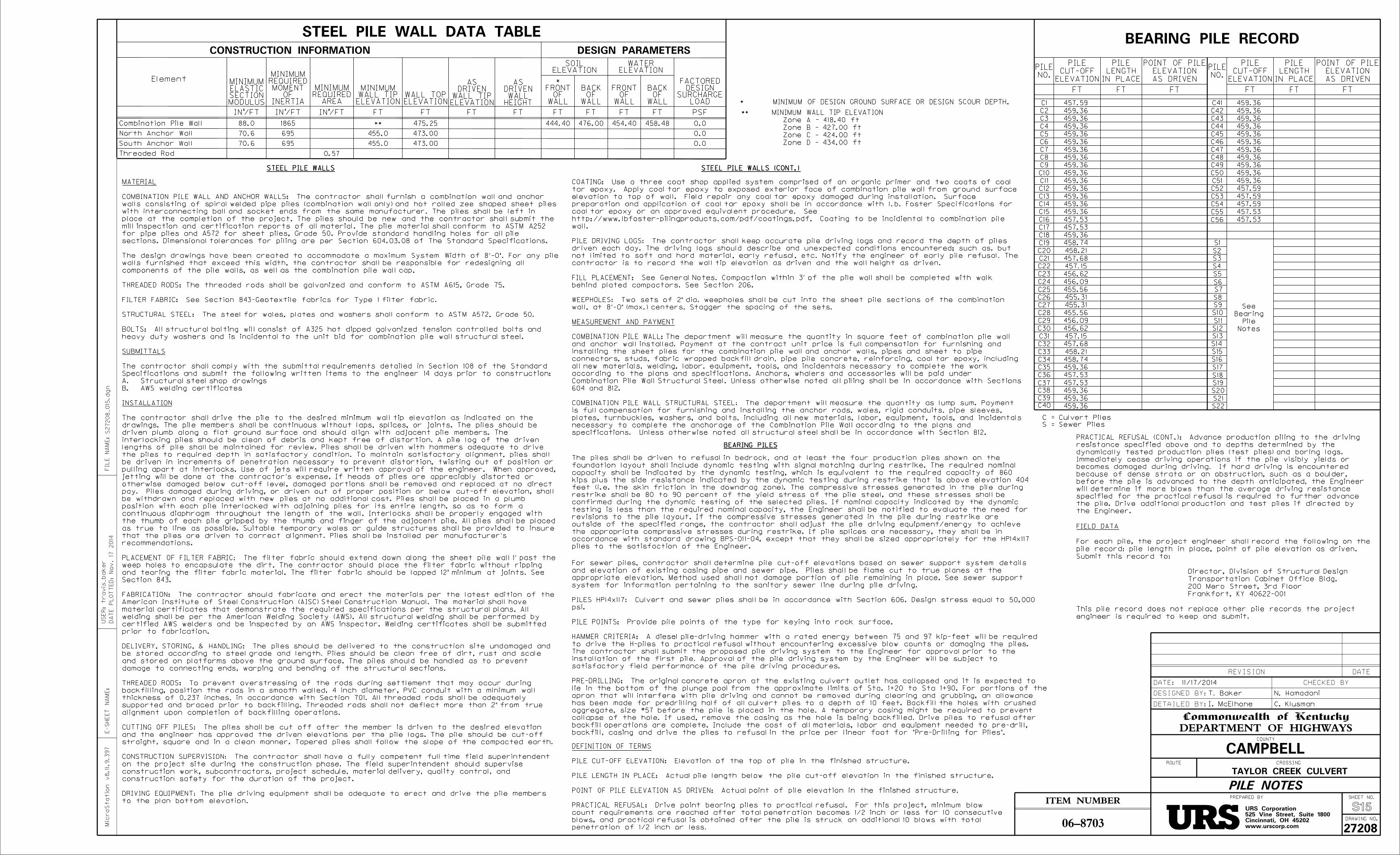
AS DRIVEN
ELEVATION
POINT OF PILE
IN PLACE
LENGTH
PILE
ELEVATION
CUT-OFF
PILE
NO.
PILE
CONSTRUCTION INFORMATION
FT
FT FT FT
FT PSF
DESIGN PARAMETERS
AS DRIVEN
ELEVATION
POINT OF PILE
IN PLACE
LENGTH
PILE
ELEVATION
CUT-OFF
PILE
NO.
PILE
FT FT FT
C1
C2
C3
C4
C5
C6
C7
C8
C9
S1
ELEVATIONWATER
0.0
FT FT
WALLOF
FRONT
FT FT/FT3
IN
INERTIAOF
MOMENTREQUIREDMINIMUM
/FT4
IN
ELEVATIONWALL TIPMINIMUM
ELEVATIONWALL TOP
ELEVATIONSOIL
WALLOF
BACK
WALLOF
BACK
LOADSURCHARGE
DESIGNFACTORED
457.59
459.36
459.36
459.36
459.36
459.36
459.36
459.36
459.36
459.36
459.36
459.36
459.36
459.36
459.36
457.53
457.53
459.36
458.74
458.21
457.68
457.15
456.62
456.09
455.56
455.31
T. Baker N. Hamadani
I. McElhone C. Klusman
FT FT
ELEVATIONWALL TIP
DRIVENAS
HEIGHTWALL
DRIVENAS
455.31
C10
C11
C12
C13
C14
C15
C16
C17
C18
C19
C20
C21
C22
C23
C24
C25
C26
C27
C28
C29
C30
C31
C32
C33
C34
C35
C36
C37
C38
C39
C40
C41
C42
C43
C44
C45
C46
C47
C48
C49
C50
C51
C52
C53
C54
S2
S3
S4
S5
S6
S7
S8
S9
S10
S11
S12
S13
S14
S15
S16
S17
S18
S19
S20
S15
C55
C56
STEEL PILE WALL DATA TABLE
Element
Combination Pile Wall
North Anchor Wall
South Anchor Wall
Threaded Rod
0.0455.0
0.0455.0
88.0
70.6
70.6
1865
695
695
475.25
473.00
473.00
444.40 454.40 458.48
MODULUSSECTIONELASTICMINIMUM
WALLOF
FRONT*
PILE NOTES
476.00
/FT2
IN
AREAREQUIREDMINIMUM
0.57
STEEL PILE WALLS
BEARING PILES
STEEL PILE WALLS (CONT.)
BEARING PILE RECORD
455.56
456.09
456.62
457.15
457.68
458.21
458.74
459.36
457.53
457.53
459.36
459.36
459.36
459.36
459.36
459.36
459.36
459.36
459.36
459.36
459.36
459.36
459.36
459.36
457.59
457.59
457.59
457.53
457.53
Notes
Pile
Bearing
See
S21
S22
C = Culvert Piles
S = Sewer Piles
S27208_015.dgn
E-S
HE
ET
NA
ME:
Micro
Statio
n v8.11.9.397
ITEM NUMBER
DRAWING NO.
SHEET NO.
Commonwealth of Kentucky
DEPARTMENT OF HIGHWAYSCOUNTY
ROUTE CROSSING
PREPARED BY
DETAILED BY:
DESIGNED BY:
DATE: CHECKED BY
REVISION DATE
06-8703
CAMPBELL
TAYLOR CREEK CULVERT
www.urscorp.comCincinnati, OH 45202525 Vine Street, Suite 1800URS Corporation
FIL
E
NA
ME:
27208
engineer is required to keep and submit.
This pile record does not replace other pile records the project
Frankfort, KY 40622-001
200 Mero Street, 3rd Floor
Transportation Cabinet Office Bldg.
Director, Division of Structural Design
Submit this record to:
pile record: pile length in place, point of pile elevation as driven.
For each pile, the project engineer shall record the following on the
FIELD DATA
piles to the satisfaction of the Engineer.
accordance with standard drawing BPS-011-04, except that they shall be sized appropriately for the HP14x117
the appropriate compressive stresses during restrike. If pile splices are necessary, they shall be in
outside of the specified range, the contractor shall adjust the pile driving equipment/energy to achieve
revisions to the pile layout. If the compressive stresses generated in the pile during restrike are
testing is less than the required nominal capacity, the Engineer shall be notified to evaluate the need for
confirmed during the dynamic testing of the selected piles. If nominal capacity indicated by the dynamic
restrike shall be 80 to 90 percent of the yield stress of the pile steel, and these stresses shall be
feet (i.e. the skin friction in the downdrag zone). The compressive stresses generated in the pile during
kips plus the side resistance indicated by the dynamic testing during restrike that is above elevation 404
capacity shall be indicated by the dynamic testing, which is equivalent to the required capacity of 860
foundation layout shall include dynamic testing with signal matching during restrike. The required nominal
The piles shall be driven to refusal in bedrock, and at least the four production piles shown on the
backfill, casing and drive the piles to refusal in the price per linear foot for "Pre-Drilling for Piles".
backfill operations are complete. Include the cost of all materials, labor and equipment needed to pre-drill,
collapse of the hole. If used, remove the casing as the hole is being backfilled. Drive piles to refusal after
aggregate, size #57 before the pile is placed in the hole. A temporary casing might be required to prevent
has been made for predrilling half of all culvert piles to a depth of 10 feet. Backfill the holes with crushed
apron that will interfere with pile driving and cannot be removed during clearing and grubbing, an allowance
lie in the bottom of the plunge pool from the approximate limits of Sta. 1+20 to Sta 1+90. For portions of the
PRE-DRILLING: The original concrete apron at the existing culvert outlet has collapsed and it is expected to
satisfactory field performance of the pile driving procedures.
installation of the first pile. Approval of the pile driving system by the Engineer will be subject to
The contractor shall submit the proposed pile driving system to the Engineer for approval prior to the
to drive the H-piles to practical refusal without encountering excessive blow counts or damaging the piles.
HAMMER CRITERIA: A diesel pile-driving hammer with a rated energy between 75 and 97 kip-feet will be required
PILE POINTS: Provide pile points of the type for keying into rock surface.
psi.
PILES HP14x117: Culvert and sewer piles shall be in accordance with Section 606. Design stress equal to 50,000
system for information pertaining to the sanitary sewer line during pile driving.
appropriate elevation. Method used shall not damage portion of pile remaining in place. See sewer support
and elevation of existing casing pipe and sewer pipe. Piles shall be flame cut to true planes at the
For sewer piles, contractor shall determine pile cut-off elevations based on sewer support system details
**
MINIMUM OF DESIGN GROUND SURFACE OR DESIGN SCOUR DEPTH.*
Zone D - 434.00 ft
Zone C - 424.00 ft
Zone B - 427.00 ft
Zone A - 418.40 ft
** MINIMUM WALL TIP ELEVATION
11/17/2014
DA
TE P
LO
TT
ED:
No
v. 17 2014
travis
_baker
US
ER:
wall.
http://www.lbfoster-pilingproducts.com/pdf/coatings.pdf. Coating to be incidiental to combination pile
Specifications for coal tar epoxy or an approved equivalent procedure. See
Surface preparation and application of coal tar epoxy shall be in accordance with l.b. Foster
surface elevation to top of wall. Field repair any coal tar epoxy damaged during installation.
coal tar epoxy. Apply coal tar epoxy to exposed exterior face of combination pile wall from ground
COATING: Use a three coat shop applied system comprised of an organic primer and two coats of
to the plan bottom elevation.
DRIVING EQUIPMENT: The pile driving equipment shall be adequate to erect and drive the pile members
construction safety for the duration of the project.
construction work, subcontractors, project schedule, material delivery, quality control, and
on the project site during the construction phase. The field superintendent should supervise
CONSTRUCTION SUPERVISION: The contractor shall have a fully competent full time field superintendent
straight, square and in a clean manner. Tapered piles shall follow the slope of the compacted earth.
and the engineer has approved the driven elevations per the pile logs. The pile should be cut-off
CUTTING OFF PILES: The piles shall be cut off after the member is driven to the desired elevation
alignment upon completion of backfilling operations.
supported and braced prior to backfilling. Threaded rods shall not deflect more than 2" from true
thickness of 0.237 inches, in accordance with Section 701. All threaded rods shall be adequately
backfilling, position the rods in a smooth walled, 4 inch diameter, PVC conduit with a minimum wall
THREADED RODS: To prevent overstressing of the rods during settlement that may occur during
damage to connecting ends, warping and bending of the structural sections.
and stored on platforms above the ground surface. The piles should be handled as to prevent
be stored according to steel grade and length. Piles should be clean free of dirt, rust and scale
DELIVERY, STORING, & HANDLING: The piles should be delivered to the construction site undamaged and
prior to fabrication.
certified AWS welders and be inspected by an AWS inspector. Welding certificates shall be submitted
welding shall be per the American Welding Society (AWS). All structural welding shall be performed by
material certificates that demonstrate the required specifications per the structural plans. All
American Institute of Steel Construction (AISC) Steel Construction Manual. The material shall have
FABRICATION: The contractor should fabricate and erect the materials per the latest edition of the
Section 843.
and tearing the filter fabric material. The filter fabric should be lapped 12" minimum at joints. See
weep holes to encapsulate the dirt. The contractor should place the filter fabric without ripping
PLACEMENT OF FILTER FABRIC: The filter fabric should extend down along the sheet pile wall 1' past the
recommendations.
that the piles are driven to correct alignment. Piles shall be installed per manufacturer's
as true to line as possible. Suitable temporary wales or guide structures shall be provided to insure
the thumb of each pile gripped by the thumb and finger of the adjacent pile. All piles shall be placed
continuous diaphragm throughout the length of the wall. Interlocks shall be properly engaged with
position with each pile interlocked with adjoining piles for its entire length, so as to form a
be withdrawn and replaced with new piles at no additional cost. Piles shall be placed in a plumb
pay. Piles damaged during driving, or driven out of proper position or below cut-off elevation, shall
otherwise damaged below cut-off level, damaged portions shall be removed and replaced at no direct
jetting will be done at the contractor's expense. If heads of piles are appreciably distorted or
pulling apart at interlocks. Use of jets will require written approval of the engineer. When approved,
be driven in increments of penetration necessary to prevent distortion, twisting out of position or
the piles to required depth in satisfactory condition. To maintain satisfactory alignment, piles shall
lengths of pile shall be maintained for review. Piles shall be driven with hammers adequate to drive
interlocking piles should be clean of debris and kept free of distortion. A pile log of the driven
driven plumb along a flat ground surface and should align with adjacent pile members. The
drawings. The pile members shall be continuous without laps, splices, or joints. The piles should be
The contractor shall drive the pile to the desired minimum wall tip elevation as indicated on the
INSTALLATION
AWS welding certificatesB.
Structural steel shop drawingsA.
Specifications and submit the following written items to the engineer 14 days prior to construction:
The contractor shall comply with the submittal requirements detailed in Section 108 of the Standard
SUBMITTALS
heavy duty washers and is incidental to the unit bid for combination pile wall structural steel.
BOLTS: All structural bolting will consist of A325 hot dipped galvanized tension controlled bolts and
STRUCTURAL STEEL: The steel for wales, plates and washers shall conform to ASTM A572, Grade 50.
FILTER FABRIC: See Section 843-Geotextile fabrics for Type 1 filter fabric.
THREADED RODS: The threaded rods shall be galvanized and conform to ASTM A615, Grade 75.
components of the pile walls, as well as the combination pile wall cap.
walls furnished that exceed this width, the contractor shall be responsible for redesigning all
The design drawings have been created to accommodate a maximum System Width of 8'-0". For any pile
sections. Dimensional tolerances for piling are per Section 604.03.08 of The Standard Specifications.
for pipe piles and A572 for sheet piles, Grade 50. Provide standard handling holes for all pile
mill inspection and certification reports of all material. The pile material shall conform to ASTM A252
place at the completion of the project. The piles should be new and the contractor shall submit the
with interconnecting ball and socket ends from the same manufacturer. The piles shall be left in
walls consisting of spiral welded pipe piles (combination wall only) and hot rolled zee shaped sheet piles
COMBINATION PILE WALL AND ANCHOR WALLS: The contractor shall furnish a combination wall and anchor
MATERIAL
specifications. Unless otherwise noted all structural steel shall be in accordance with Section 812.
necessary to complete the anchorage of the Combination Pile Wall according to the plans and
plates, turnbuckles, washers, and bolts, including all new materials, labor, equipment, tools, and incidentals
is full compensation for furnishing and installing the anchor rods, wales, rigid conduits, pipe sleeves,
COMBINATION PILE WALL STRUCTURAL STEEL: The department will measure the quantity as lump sum. Payment
604 and 812.
Combination Pile Wall Structural Steel. Unless otherwise noted all piling shall be in accordance with Sections
according to the plans and specifications. Anchors, whalers and accessories will be paid under
all new materials, welding, labor, equipment, tools, and incidentals necessary to complete the work
connectors, studs, fabric wrapped backfill drain, pipe pile concrete, reinforcing, coal tar epoxy, including
installing the sheet piles for the combination pile wall and anchor walls, pipes and sheet to pipe
and anchor wall installed. Payment at the contract unit price is full compensation for furnishing and
The department will measure the quantity in square feet of combination pile wall COMBINATION PILE WALL:
MEASUREMENT AND PAYMENT
wall, at 8'-0" (max.) centers. Stagger the spacing of the sets.
WEEPHOLES: Two sets of 2" dia. weepholes shall be cut into the sheet pile sections of the combination
behind plated compactors. See Section 206.
FILL PLACEMENT: See General Notes. Compaction within 3' of the pile wall shall be completed with walk
contractor is to record the wall tip elevation as driven and the wall height as driven.
not limited to soft and hard material, early refusal, etc. Notify the engineer of early pile refusal. The
driven each day. The driving logs should describe and unexpected conditions encountered; such as, but
PILE DRIVING LOGS: The contractor shall keep accurate pile driving logs and record the depth of piles
wall.
http://www.lbfoster-pilingproducts.com/pdf/coatings.pdf. Coating to be incidiental to combination pile
coal tar epoxy or an approved equivalent procedure. See
preparation and application of coal tar epoxy shall be in accordance with l.b. Foster Specifications for
elevation to top of wall. Field repair any coal tar epoxy damaged during installation. Surface
tar epoxy. Apply coal tar epoxy to exposed exterior face of combination pile wall from ground surface
COATING: Use a three coat shop applied system comprised of an organic primer and two coats of coal
penetration of 1/2 inch or less.
blows, and practical refusal is obtained after the pile is struck an additional 10 blows with total
count requirements are reached after total penetration becomes 1/2 inch or less for 10 consecutive
PRACTICAL REFUSAL: Drive point bearing piles to practical refusal. For this project, minimum blow
POINT OF PILE ELEVATION AS DRIVEN: Actual point of pile elevation in the finished structure.
PILE LENGTH IN PLACE: Actual pile length below the pile cut-off elevation in the finished structure.
PILE CUT-OFF ELEVATION: Elevation of the top of pile in the finished structure.
DEFINITION OF TERMS
the Engineer.
the pile. Drive additional production and test piles if directed by
specified for the practical refusal is required to further advance
will determine if more blows than the average driving resistance
before the pile is advanced to the depth anticipated, the Engineer
because of dense strata or an obstruction, such as a boulder,
becomes damaged during driving. If hard driving is encountered
Immediately cease driving operations if the pile visibly yields or
dynamically tested production piles (test piles) and boring logs.
resistance specified above and to depths determined by the
PRACTICAL REFUSAL (CONT.): Advance production piling to the driving

NOTES
(859) 578-6885
Ft. Wright, KY 41017
1045 Eaton Drive
Sanitation District NO. 1Bob Wilson
the project activities noted below.shall be notified a minimum of seven (7) days prior to construction and prior to remain in service and undisturbed during construction. The Sanitation District The existing aerial sanitary sewer owned by Sanitation District No. 1 (SD1) shall
S18
1. For General Notes, See Sheets S3-S5.
T. Baker
T. BakerJ. Corley
N. Hamadani
SANITATION DISTRICT 1 SANITARY SEWER SUPPORT SYSTEM
SEWER SUPPORT SYSTEM (3)
S27208_018.
DG
NFIL
E
NA
ME:
www.urscorp.comCincinnati, OH 45202525 Vine Street, Suite 1800URS Corporation
06-8703
CAMPBELL
TAYLOR CREEK CULVERT
E-S
HE
ET
NA
ME:
Micro
Statio
n v8.11.9.397
ITEM NUMBER
DRAWING NO.
SHEET NO.
Commonwealth of Kentucky
DEPARTMENT OF HIGHWAYSCOUNTY
ROUTE CROSSING
PREPARED BY
DETAILED BY:
DESIGNED BY:
DATE: CHECKED BY
REVISION DATE
27208
11/17/2014
accordance with Section 604. Excavation will be paid for with Foundation Preparation.work according to the plans and specifications. Steel Piles will be paid in support, welding, labor, equipment, tools, and incidentals necessary to complete the longitudinal support beam field splice design and details, surveying, temporary brackets, neoprene pads, plates, washers, and bolts, including all new materials, installing structural steel, longitudinal and transverse beam members, pipe support Lump sum payment for sewer support system is full compensation for furnishing and
system shall be completed with walk behind plated compactors. See Section 206.Compaction within 3'-0" to the side or above the sewer pipe and sewer support
verified to be maintained, no further surveying of the sewer is required.installed, the existing piles have been cut, and the baseline elevations have been by the engineer and SD1. Once all components of the sewer support system are engineer and SD1. The support brackets may be shimmed and re-bolted as directed If movement of the support brackets is noted, the contractor shall notify the
directed by the engineer.change in elevation occurs. The sewer support brackets may be shimmed as brackets shall be installed flush with the existing pipe and casing such that no Following installation of the sewer support brackets. The sewer support
each work week.
driving exceeds one (1) week, resurvey baseline locations at the beginning of Following pile driving for culvert and sewer piles. If the duration of pile
of the casing at intervals not to exceed 10'-0".exposed, establish baseline locations on the top of the pipe outside the limits banks to construct sewer support. Once the buried portions of pipe are Following placement of backfill in the existing plunge pool and excavation of
Following installation of the combination pile wall.
the baseline locations at the subsequent times:construction. Following the baseline measurements, the contractor shall resurvey to be maintained throughout the duration of the sewer support system the proposed fill and construction operations. These will serve as baseline elevations measured relative to an approved benchmark located outside of the influence of each existing support bracket, on the top of the strap plate. Elevations shall me Prior to the start of construction, the contractor shall take survey elevations at
support system.
pipe and casing without existing piles while excavations are in place to install sewer installed. The contractor shall provide temporary support for portions of sewer The existing piles shall not be cut until the entire sewer support system has been
shall be ASTM A36. All structural steel to be in accordance with Section 812.Steel for longitudinal beams shall be ASTM A572, Grade 50. Steel for remaining plates
All bolts shall be A325 bolts, snug tightened.
by a professional engineer licensed in the Commonwealth of Kentucky.of the field splices shall be the responsibility of the contractor and completedcontractor shall locate field splices away from the pipe support brackets. Design Field splices in the longitudinal support beam shall be either bolted or welded. The
shown on the spacing diagram.piles and supports shall be adjusted as needed to fit the existing conditions, as verify locations of existing supports, piles, and sewer pipe. The location of the new to joints in the sewer pipe based on available as-built data. Contractor shall field Sewer Replacement drawings. The support brackets have been located with respect The dimensions shown are based on the existing Taylor Creek Crossing Sanitary
DA
TE P
LO
TT
ED:
No
v. 17 2014
travis
_baker
US
ER:

2'-0"
23'-10"
16'-0"
2'-0"
Machine
14'-0"
2'-0"
Varie
s
2" (T
yp.)
CLOSURE DIAPHRAGM
S23
Culvert Floor
Regraded
DOWEL DETAIL
New Concrete
Material Before Placing
Apply Epoxy Bonding
Grout Bars with a
Non-Shrinking Grout
Existing
Concrete
1'-0"
grouting, and epoxy bonding
material shall be incidental to
Note: The cost of drilling holes,
1'-9"
T. Baker
T. Baker
N. Hamadani
J. Corley
3-Sided Culvert
SECTION A-A
LiningReinforced Concrete
SECTION C-C
3-Sided Culvert
LiningReinforced Concrete
Foundation
Culvert
Existing Slab
Preparation of
SECTION B-B
END ELEVATION
A
A
B
B
Concrete Lining
Culvert and Reinforced
Remove Existing 3-Sided
C
C
Culvert Foundation
Remove Existing
EXISTING CULVERT REMOVAL
*
**Foundation
Culvert
To Remain
Existing Culvert
#6 Dowel
Closure Diaphragm
the cost of Closure Diaphragm.
Closure Diaphragm
3-Sided Culvert Manufacturer Details
per 3-Sided Culvert
Waterproof Joint
Existing 3-Sided Culvert
Max.
1'-3ƒ
" (+/-)
3"
Min. to
Closure Diaphragm
NOTES
#6 Bar
CLOSURE DIAPHRAGM ELEVATION
or Dowel Bars
Existing Reinforcing
Closure Diaphragm.
Reinforced Concrete Lining into
Horizontal Reinforcement Bars From
* Clean and Incorporate Existing
#6 Bar (Typ.)
#6 Dowel Bar (Typ.)
Existing Reinforcing or
Foundation Walls and Bottom Slab.
Culvert Foundation into Culvert
Horizontal Reinforcement Bars From
** Clean and Incorporate Existing
Culvert Floor
Regraded
Details
See Culvert Foundation
S27208_023.
DG
NFIL
E
NA
ME:
Wall
Foundation
Culvert
Exist.
Top of
S19-S22
3. For Culvert Foundation, See Sheets
2. For Culvert Profile, See Sheet S8.
1. For General Notes, See Sheets S3-S5.
CLOSURE DIAPHRAGM
Bars (T
yp.)
12"
Max
For
Do
wel
www.urscorp.comCincinnati, OH 45202525 Vine Street, Suite 1800URS Corporation
06-8703
CAMPBELL
TAYLOR CREEK CULVERT
E-S
HE
ET
NA
ME:
Micro
Statio
n v8.11.9.397
ITEM NUMBER
DRAWING NO.
SHEET NO.
Commonwealth of Kentucky
DEPARTMENT OF HIGHWAYSCOUNTY
ROUTE CROSSING
PREPARED BY
DETAILED BY:
DESIGNED BY:
DATE: CHECKED BY
REVISION DATE
27208
Engineer, drilled and grouted dowel bars shall be used.
reinforcement is deemed unsuitable to be reused by the
walls, and bottom slab. In the event the existing
the cast-in-place closure diaphragm, culvert foundation
existing reinforcement that is to be reused as part of
last 2'-0" of existing culvert, to minimize the damage to
The contractor shall exercise caution when removing the
11/17/2014
LUMP SUMCLOSURE DIAPHRAGM
The Department will measure the quantity as:
reinforcing steel shall be in accordance with Section 602.
Concrete shall be in accordance with Section 601 and
the interior limits of the existing reinforced concrete lining.
hydraulic capacity of the culvert and shall not extend beyond
Completed closure diaphragm shall not reduce the current
project.
the manufacturer of the three-sided culvert utilized for the
details for the closure diaphragm shall be coordinated with
reinforcement for approval prior ordering materials. The
illustrating the proposed details of the concrete and
The contractor shall furnish shop drawings to the engineer
engineer licensed in the Commonwealth of Kentucky.
of closure diaphragm shall be stamped by a professional
diaphragm and the existing reinforced concrete lining. Design
reinforced concrete lining or dowel bars between the closure
incorporate horizontal reinforcing from the existing
specifications. Closure diaphragm shall be designed to
necessary to complete the work according to the plans and
as needed, including all labor, equipment, tools, and incidentals
exterior water proofing at joints, and diverting culvert flow
existing and proposed three sided culvert, application of
steel reinforcing for the closure diaphragm between the
for designing, detailing, furnishing, and installing concrete and
The lump sum bid price for this item shall be full compensation
Diaphragm Design
Reinforcing per Closure
DA
TE P
LO
TT
ED:
No
v. 17 2014
travis
_baker
US
ER:

PROPOSAL BID ITEMS
Report Date 12/9/14Page 1 of 2
141299
Section: 0001 - DRAINAGELINE BID CODE ALT DESCRIPTION QUANTITY UNIT UNIT PRIC FP AMOUNT0010 00524 STORM SEWER PIPE-24 IN 81.00 LF $0020 01310 REMOVE PIPE 14.00 LF $0030 01496 DROP BOX INLET TYPE 3 1.00 EACH $0040 01756 MANHOLE TYPE A 1.00 EACH $0050 01761 MANHOLE TYPE B 1.00 EACH $0060 01792 ADJUST MANHOLE 1.00 EACH $
Section: 0002 - BRIDGE - RIVERBOAT ROAD - TAYLOR CREEK CULVER- DWG. 27208LINE BID CODE ALT DESCRIPTION QUANTITY UNIT UNIT PRIC FP AMOUNT0070 00071 CRUSHED AGGREGATE SIZE NO 57 4,539.00 TON $0080 02230 EMBANKMENT IN PLACE 5,937.00 CUYD $0090 02231 STRUCTURE GRANULAR BACKFILL 5,617.00 CUYD $
0100 02545CLEARING AND GRUBBING(UNKNOWN ACREAGE) 1.00 LS $
0110 02650 MAINTAIN & CONTROL TRAFFIC 1.00 LS $0120 02726 STAKING 1.00 LS $0130 02731 REMOVE STRUCTURE 1.00 LS $0140 02998 MASONRY COATING 165.00 SQYD $0150 05985 SEEDING AND PROTECTION 3,304.00 SQYD $0160 08003 FOUNDATION PREPARATION 1.00 LS $0170 08019 CYCLOPEAN STONE RIP RAP 194.00 TON $0180 08033 TEST PILES 376.00 LF $
0190 08039PRE-DRILLING FOR PILES(REVISED: 12-9-14) 390.00 LF $
0200 08052 PILES-STEEL HP14X117 7,029.00 LF $0210 08095 PILE POINTS-14 IN 78.00 EACH $0220 08100 CONCRETE-CLASS A 358.00 CUYD $0230 08106 CONCRETE-CLASS M 1 104.00 CUYD $0240 08150 STEEL REINFORCEMENT 53,000.00 LB $0250 08551 MACHINE PREP OF SLAB 356.00 SQYD $0260 21804EN 3-SIDED CULVERT 133.00 LF $
0270 23143EDKPDES PERMIT AND TEMP EROSIONCONTROL 1.00 LS $
0271 23233ECDYNAMIC PILE TESTING(ADDED: 12-9-14) 4.00 EACH $
0280 23315EC DECORATIVE FENCE 202.00 LF $0290 24246EC REMOVE ABANDONED SANITARY SEWER 40.00 LF $0300 24423EC TEMPORARY SHORING 1.00 LS $0310 24630EC TYPE B ARMOR ROCK 351.00 TON $0320 24754ED SETTLEMENT MONITORING 1.00 LS $0330 24756EC COMBINATION PILE WALL 11,309.00 SQFT $
0340 24757ECCOMBINATION PILE WALL STRUCTURALSTEEL 1.00 LS $
0350 24758EC SEWER SUPPORT SYSTEM 1.00 LS $0360 24759EC PUMPED GROUT 100.00 CUFT $0370 24761EC CLOSURE DIAPHRAGM 1.00 LS $
CAMPBELL COUNTYFD04 019 0008 CUL EXT
REVISED: 12-9-14Contract ID: 141299
Page 72 of 73

PROPOSAL BID ITEMS
Report Date 12/9/14Page 2 of 2
141299
Section: 0003 - DEMOBILIZATION &/OR MOBILIZATIONLINE BID CODE ALT DESCRIPTION QUANTITY UNIT UNIT PRIC FP AMOUNT0380 02568 MOBILIZATION 1.00 LS $0390 02569 DEMOBILIZATION 1.00 LS $
CAMPBELL COUNTYFD04 019 0008 CUL EXT
REVISED: 12-9-14 Contract ID: 141299
Page 73 of 73

06-8703
Special Note for Dynamic Pile Testing Page 1 of 11 Rev. 12/08/2014
SPECIAL NOTE FOR DYNAMIC PILE TESTING
Campbell County (Item No. 06-8703)
Riverboat Row Taylor Creek Culvert Extension
1.0 GENERAL
1.1 Scope of Work The scope of work includes furnishing all labor, equipment and
analyses associated with dynamic testing of driven piles for the culvert foundations as specified
in this Special Note and in general accordance with ASTM D 4945, High-Strain Dynamic
Testing of Piles. Dynamic testing involves attaching at least two strain transducers and two
accelerometers to the pile near the pile head during initial driving or at a convenient location
during restrike testing. A cable or wireless transmission connects the sensors near the pile head
with the Pile Driving Monitoring Hardware located a safe distance from the pile, but not more
than 330 ft from the pile. The piles that are to be tested must be of sufficient extra length to
ensure that sensors are not driven into the ground.
1.2 Personnel Qualifications Perform dynamic pile testing utilizing the services of an
independent Dynamic Pile Testing Consultant with qualified personnel as described below.
• Pile Driving Monitoring - An engineer with a minimum of 3 years of dynamic pile testing
and analysis experience or who has achieved Basic or better certification under the High-
Strain Dynamic Pile Testing Examination and Certification process of the Pile Driving
Contractors Association or Foundation QA.
• Wave Equation and Pile Driving Analyses - A licensed professional engineer with a
minimum of 5 years of dynamic pile testing and analysis experience or who has achieved
Advanced or better certification under the High-Strain Dynamic Pile Testing
Examination and Certification process of the Pile Driving Contractors Association or
Foundation QA.
1.3 Equipment Supply equipment such as sensors, cables or wireless transmitters, etc.
conforming to ASTM D 4945, High-Strain Dynamic Testing of Piles and furnished by the
dynamic testing consultant. Prior to beginning work, submit the product name and manufacturer
of the hardware and software components below for acceptance by the Engineer. If requested by
the Engineer, submit additional information including technical specifications, etc.
• Pile Driving Modeling - Wave Equation Software
• Pile Driving Monitoring - Hardware & Software
• Pile Driving Analysis - Signal Matching Software
To prepare the pile for sensor attachment, provide a drill (and bit) of sufficient power, operated
by either a DC battery (preferred) or a generator. A hammer drill is required for preparation of
concrete piles.
CAMPBELL COUNTYFD04 019 0008 CUL EXT
ADDED: 12-9-14Contract ID: 141299
Page 1 of 15

06-8703
Special Note for Dynamic Pile Testing Page 2 of 11 Rev. 12/08/2014
1.4 Submittals and General Testing & Analysis Requirements See Tables 1 and 2 on
the following page. The Engineer will respond to the Contractor regarding acceptability of
submittals as soon as practical.
Table 1 - Schedule of Dynamic Pile Testing Submittals
Submittal
Number
Submittal
Item
Calendar
Days Event 1 Proposed independent dynamic pile testing
consultant, and a listing of assigned personnel and their experience and qualifications.
45 Before Start of
Pile Driving Monitoring
2 Details of the hardware and software components,
method of testing, and materials to be used.
45 Before Start of
Pile Driving
Monitoring
3 Completed Pile and Driving Equipment Data Form
(Figure 1 of this Special Note) and the results of
wave equations analyses.
21 Before Start of
Pile Driving
Monitoring
4 Preliminary Reports as defined in Section 3.1 of this Special Note.
1 After Completion of Each Field Test
5 Summary Report(s) as defined in Section 3.2 of this
Special Note.
10 After Completion of All
Field Tests
Provide all submittals and reports in .pdf format.
Table 2 - General Testing and Analysis Requirements
Item Requirement Wave Equation Analysis Minimum of 1 and sufficient additional analyses as needed to define
performance for all combinations of piles, driving systems and
subsurface conditions anticipated.
Dynamic Testing Pile
Resistance (i.e. Capacity)
Required Nominal Pile Resistance (i.e. Ultimate Pile Capacity) as
shown in the plans and/or as directed by the Engineer.
End of Initial Driving Test Frequency Minimum of 4 production piles at the locations shown in the plans or
as directed by the Engineer during the final 25 feet of initial driving
Beginning of Restrike Test Frequency Minimum of 4 production piles at the locations shown in the plans f or
as directed by the Engineer.
Time Interval between End of Initial
Driving and Restrike
Minimum of 7 days unless stated otherwise elsewhere in the contract
documents and/or directed otherwise by the Engineer based on the
criteria below.
Soil Type Time Delay Until Restrike
Clean Sands 24 hours
Silty Sands 48 hours
Sandy Silts 72 – 120 hours
Silts and Clays 7 - 14 Days
Shales 7 Days
Pile Driving Analyses using Signal
Matching Techniques
For each End of Initial Driving Test and each Beginning of Restrike
Test
CAMPBELL COUNTYFD04 019 0008 CUL EXT
ADDED: 12-9-14Contract ID: 141299
Page 2 of 15

06-8703
Special Note for Dynamic Pile Testing Page 3 of 11 Rev. 12/08/2014
Table 2 - General Testing and Analysis Requirements
Item Requirement
Perform testing and analyses in accordance with this table and ASTM D 4945, High-Strain
Dynamic Testing of Piles.
CAMPBELL COUNTYFD04 019 0008 CUL EXT
ADDED: 12-9-14Contract ID: 141299
Page 3 of 15

06-8703
Special Note for Dynamic Pile Testing Page 4 of 11 Rev. 12/08/2014
2.0 TESTING AND ANALYSES
2.1 Preconstruction Wave Equation Analyses At least 21 calendar days before
beginning pile driving monitoring submit to the Engineer the completed Pile and Driving
Equipment Data Form (Figure 1 of this Special Note) and preconstruction wave equation
analyses performed by the Dynamic Pile Testing Consultant in accordance with Table 2 in this
Special Note and a summary report of the results. The required nominal resistance (i.e. ultimate
capacity) is provided in the plans and/or elsewhere in the contract documents. Upon request, the
Geotechnical Report for the project can be provided.
The purpose of the wave equation analyses is to assess the ability of all proposed pile driving
systems to install piles to the required nominal resistance (i.e. ultimate capacity) and the desired
penetration depth within allowable driving stresses. Acceptability of the wave equation report
and the adequacy of analyses will be determined by the Engineer. In the Wave Equation
Summary Report, include:
a. drivability graph relating pile resistance (i.e. capacity), blow count and driving
stresses to depth;
b. bearing graph relating the pile resistance (i.e. capacity) to the pile driving resistance
which indicates blow count versus resistance (i.e. capacity) and stroke; and
c. constant resistance (i.e. capacity) analysis or inspectors chart to assist the Engineer in
determining the required driving resistance at other field-observed strokes.
2.1.1 Acceptance by the Engineer of the proposed pile driving system will be based upon
the wave equation analyses indicating that the proposed system can develop the specified
pile resistance (i.e. capacity) at a pile driving rate of 20 blows per inch (240 blows/ft.) at
the end of driving and beginning of restrike, and within allowable driving compressive
stress of 80 to 90% of the yield stress of the piles. Provide preliminary pile driving
criteria based on wave equation analyses and any anticipated resistance (i.e. capacity)
changes after driving, set-up or relaxation, subject to revision based upon dynamic pile
testing field measurements.
2.1.2 If any changes or modifications are made to the accepted pile driving system,
additional wave equation analyses in accordance with Section 2.1 of this Special Note
will be required.
2.2 High-Strain Dynamic Pile Testing
2.2.1 Perform dynamic pile testing at the locations and frequency required in
accordance with Table 2 in this Special Note.
2.2.2 Dynamic pile testing involves monitoring the response of a pile subjected to
heavy impact applied by the pile hammer at the pile head. The testing will provide
information on the driving stresses, pile resistance (i.e. capacity), structural integrity, and
hammer efficiency.
CAMPBELL COUNTYFD04 019 0008 CUL EXT
ADDED: 12-9-14Contract ID: 141299
Page 4 of 15

06-8703
Special Note for Dynamic Pile Testing Page 5 of 11 Rev. 12/08/2014
2.2.3 Engage an independent dynamic pile testing consultant and qualified personnel in
accordance with Section 1.2 of this Special Note. Prior to testing, the Engineer will
review and accept the proposed independent dynamic pile testing consultant, the
experience and qualifications of assigned personnel, details of the method of testing, a list
of equipment, and the method of analysis of test results.
2.2.4 Perform all field testing and measurements in the presence of the Engineer or
authorized representative.
2.2.5 Remote Dynamic Pile Testing where data is collected in the field and sent to the
office of the Dynamic Pile Testing Consultant will not be allowed on this project. The
testing consultant is required to have at least one person meeting the requirements for
“Pile Driving Monitoring” as defined in Section 1.2 of the Special Note for Dynamic Pile
Testing in the field during all dynamic pile testing. However, “wireless” technology that
eliminates cables from the test pile to the data acquisition equipment will be allowed.
2.3 Field Testing
2.3.1 Equipment Perform dynamic pile testing field measurements using equipment,
software and recording equipment accepted in accordance with Section 1.4 of this Special
Note. Analyze the data collected at the end of initial driving and the beginning of restrike
using accepted signal matching techniques and software.
2.3.2 Monitoring During Driving During pile driving, instrument the piles and
monitor them with testing equipment satisfying the requirements of Section 1.3 of this
Special Note. Prior to lifting the pile to be dynamically tested, provide a minimum of 3 ft
of clear access to 180 degree opposite faces of the pile for pile preparation then drill and
prepare holes for sensor attachment. Sensors are usually attached near the pile top.
2.3.2.1 Install two sets of strain transducers and accelerometers near the
top of each pile to be tested, and use a compatible measuring and recording
system to record the data during driving.
2.3.2.2 Appropriately position and fix the equipment required to be
attached to the pile to the satisfaction of the Engineer.
2.3.2.3 Use a pile driving hammer and other equipment capable of
delivering an impact force sufficient to mobilize the specified pile resistance (i.e.
capacity) indicated in the structure plans without damaging the pile.
2.3.2.4 Use the testing equipment to monitor pile stresses during driving to
prevent pile damage and ensure pile integrity and resistance (i.e. capacity). If the
testing equipment indicates overstressing or damage to the pile, immediately
discontinue driving and notify the Engineer and propose a new pile driving
system, modifications to existing system, or new pile installation procedures.
Acceptance by the Engineer of any proposed changes to the pile driving system or
pile installation procedures will be based upon the results of additional wave
equation analyses in accordance with Section 2.1.2 of this Special Note.
CAMPBELL COUNTYFD04 019 0008 CUL EXT
ADDED: 12-9-14Contract ID: 141299
Page 5 of 15

06-8703
Special Note for Dynamic Pile Testing Page 6 of 11 Rev. 12/08/2014
2.3.3 Preparation of the Pile Head The preparation of the pile head for the
application of dynamic test load may involve, where appropriate, trimming the head,
cleaning, and building up the pile using materials that, at the time of testing, safely
withstand the impact stresses. Provide an impact surface that is flat and at right angles to
the pile axis.
2.3.4 Dynamic Measurement and Analysis Begin monitoring of pile driving when pile
driving begins. Record and process the data immediately in the field by the pile driving
monitoring equipment and software. Unless monitoring indicates that additional driving
will damage the pile, continue pile driving and monitoring until both the specified pile tip
elevation and the specified pile resistance (i.e. capacity) are reached. When the level of
the sensors is within 1 foot of any obstruction endangering the survival of sensors or
cables, halt driving to remove the sensors from the pile. If additional driving is required,
remove the obstruction or splice the pile and reattach the sensors to the head of the next
pile segment prior to resuming driving. For each pile tested, perform pile driving analysis
using signal matching techniques for a selected blow at the end of driving (EOD) to
determine the relative capacities from end bearing and skin friction along the pile.
Unless stated elsewhere in the contract documents or directed otherwise by the Engineer
use the table below to determine the pile resistance (i.e. capacity) required at EOD.
Soil
Type
Setup
Factor
EOD Resistance as a % of
Required Nominal Resistance
Clay 2.0 ≈ 50%
Silt-Clay & Sand-Clay 1.5 ≈ 70%
Sand-Silt & Fine Sand 1.2 ≈ 85%
Sand & Sand-Gravel 1.0 ≈ 100%
Make any required adjustments to the fuel and/or power setting of the hammer if
necessary to verify the resistance at a pile driving rate of 20 blows per inch (240
blows/ft.) at the end of driving and beginning of restrike and within allowable driving
compressive stress of 80 to 90% of the yield stress of the piles or to meet other applicable
testing objectives.
2.3.4.1 Perform beginning of restrike (BOR) tests at the frequency
indicated in Table 2 of this Special Note with the time interval between end of
initial driving and beginning of restrike in accordance with Table 2 of this Special
Note. During restrike, instrument and monitor the pile in a manner similar to that
used during initial driving. For each restrike test, perform pile driving analysis
using signal matching techniques for a selected blow from the beginning of
restrike to determine the relative capacities from end bearing and skin friction
along the pile.
CAMPBELL COUNTYFD04 019 0008 CUL EXT
ADDED: 12-9-14Contract ID: 141299
Page 6 of 15

06-8703
Special Note for Dynamic Pile Testing Page 7 of 11 Rev. 12/08/2014
2.3.4.2 Perform the restrike test after warming up the hammer by driving
another non-test production pile. If overstressing or damage to the test pile is
indicated, immediately discontinue driving and notify the Engineer. In the event
initial restrike testing indicates a pile resistance below the specified resistance, an
additional restrike test after the redrive may be required as directed by the
Engineer.
2.3.4.3 The Engineer may request use of pile driving monitoring
equipment and software on additional piles if inconclusive results are obtained or
unusual driving conditions are encountered.
2.3.4.4 Evaluate pile resistance and integrity based on the standard
procedure used in practice.
2.3.4.5 Immediately provide tabular records of the dynamic pile testing
field measurements obtained at the end of initial driving and at the beginning of
restrike to the Engineer.
3.0 DYNAMIC PILE TEST REPORTS
3.1 Preliminary Dynamic Pile Test Reports Submit a preliminary test report for each
pile tested for review by the Engineer. In the reports, include tabular as well as graphical
presentation of the dynamic test results versus depth and proposed pile driving criteria for the
additional piles to be installed at the substructure unit of the pile tested. Also include the
following:
a. The maximum force applied to the pile head.
b. The maximum pile head velocity.
c. The maximum energy imparted to the pile.
d. The assumed soil damping factor and wave speed.
e. Static resistance (i.e. capacity) estimate.
f. The maximum compressive and tensile forces in the pile.
g. Pile integrity.
h. Blows per inch.
i. Stroke.
j. Summary results of pile driving analysis from up to three selected blows analyzed using
signal matching techniques and software.
k. Results of refined wave equation analyses based upon dynamic testing signal matching
analysis, including tabular and graphical inspector’s charts at EOD and BOR for the
required pile resistance values specified for each specific substructure.
The Engineer will use the results of the preliminary reports to provide pile driving criteria for
production piles to the Contractor.
3.2 Dynamic Pile Test Summary Report Submit a summary report of all piles tested
on each structure for review by the Engineer. (Where phased construction is used it may be
CAMPBELL COUNTYFD04 019 0008 CUL EXT
ADDED: 12-9-14Contract ID: 141299
Page 7 of 15

06-8703
Special Note for Dynamic Pile Testing Page 8 of 11 Rev. 12/08/2014
desirable to provide different reports for each phase. In such cases, the contractor should seek
the approval of the Engineer.) In the report, include the results of hammer performance, pile
driving stresses, and pile resistance during initial driving and restrike for all piles tested. Also
include the following:
a. Identification of the structure, including: County, Route, Crossing, and Drawing Number.b. Date of testing and date of pile installation.
c. Pile identification number and location.
d. All information given in preliminary reports as follows:
1. Length of pile below the surface.2. Total length of pile, including projection above the surface at time of test.
3. Length of pile from instrumentation position to tip.
e. Hammer type, drop, and other relevant details.f. Blow selected for signal matching analysis.
g. Maximum compressive and tensile stresses, stroke, and resistance (i.e. capacity) versus
penetration depth.h. Temporary compression.
i. Pile integrity and location of damage, if any.
j. Force/velocity versus time trace.
k. Force/velocity match curve.l. Resistance distribution along the pile.
m. Detailed graphical and tabular results from up to three selected blows analyzed using signal
matching techniques and software.
n. Results of refined wave equation analyses based upon dynamic testing signal matching
analysis, including tabular and graphical inspector’s charts at EOD and BOR for the
required pile resistance values for each specific substructure.
4.0 INCIDENTAL EQUIPMENT
Prior to the beginning of dynamic testing, provide one electronic device to aid in recording pile
hammer blows, stroke, and energy such as an "E-Saximeter" or accepted equivalent meeting the
specifications in the Appendix to this Special Note. This device will immediately become
property of the Department for use on the project.
Provide field training by someone proficient in the use of the device to ensure that
approximately 3 to 5 employees of the Department are competent in the use of the device. This
training may be performed by a representative of the independent Dynamic Pile Testing
Consultant who is proficient in the use of the device or a manufacturer's representative. The
required training time is anticipated to be no more than one day.
The cost of furnishing this device and providing the training is incidental to the contract price for
"Dynamic Pile Testing" and no separate payment will be made.
CAMPBELL COUNTYFD04 019 0008 CUL EXT
ADDED: 12-9-14Contract ID: 141299
Page 8 of 15

06-8703
Special Note for Dynamic Pile Testing Page 9 of 11 Rev. 12/08/2014
5.0 METHOD OF MEASUREMENT AND BASIS OF PAYMENT
Dynamic pile testing will be measured per each. Payment for each restrike test performed will
be in addition to payment for each test performed at the end of initial driving. Payment for
redrive testing will be included in the price for the restrike test immediately prior to the redrive.
Payment for each test will include pile driving monitoring and pile driving analysis performed.
Payment for the above described work, including all material, equipment, tools, labor and any
other incidental work necessary to complete this item.
Payment will be made under:
Pay Item Pay Unit
23233EC Dynamic Pile Testing Each
CAMPBELL COUNTYFD04 019 0008 CUL EXT
ADDED: 12-9-14Contract ID: 141299
Page 9 of 15

06-8703
Special Note for Dynamic Pile Testing Page 10 of 11 Rev. 12/08/2014
90
Figure 1
Pile and Driving Equipment Data Form (From FHWA-HI-097-014)
(ft. - lb.)
(ft.)
(ft. - lb.)
(ft.)
(lb.)
(lb.)
(in.)
(in.)
(in.2)
(in.)
(in.2)
(in.2) (in.)
(in.)
(lb.)
(in.)
(ft.)
(kips)
(kips)
(in.)
(in.2) Weight/Foot
CAMPBELL COUNTYFD04 019 0008 CUL EXT
ADDED: 12-9-14Contract ID: 141299
Page 10 of 15

06-8703
Special Note for Dynamic Pile Testing Page 11 of 11 Rev. 12/08/2014
Appendix
Physical:
Size: 100mm X 190mm X 50mm (4 inches X 7.5 inches X 2 inches)
Weight: 0.7 kg (1.5 lb.)
Temperature range: -10 to 50°C (14 to 104°F) operating
Power: built-in rechargeable battery w/ 8 hour min duration
Display: LCD, 4 Lines x 16 characters, viewing area 62 mm by 26 mm (2.5 inches
by 1 inch)
Keypad: Large key (1.27 mm2 ), non tactile
Electronic:
32 bit microcontroller up to 20.97 MHz
12 bit digital to analog converter 8 bit 4 channel analog to digital converter
Internal microphone 70 to 115 dB
RS232 connector for data transfer
4 MB internal memory
Functional and Other:
Maximum blow detection rate: 68 bpm for open end diesel hammers; 300 bpm for all others
Furnished with SAXLINK program for data transfer in text format
Operates in English or SI units
Full one year warranty
Technical manual included
CAMPBELL COUNTYFD04 019 0008 CUL EXT
ADDED: 12-9-14Contract ID: 141299
Page 11 of 15

CAMPBELL 06-8703
Page 1 of 4
VIBRATION MONITORING
1.0 DESCRIPTION
This Special Note will apply when indicated on the plans or in the proposal. Section
references herein are to the Department’s 2012 Standard Specifications for Road and
Bridge Construction.
This item shall include all labor, equipment, materials and incidental items for the
following:
The Contractor shall retain a qualified Consultant to perform vibration monitoring during
construction of the temporary shoring and pile installation for the Combination Pile Wall,
sewer support system, and culvert base slab as well as any other construction deemed
necessary by the Engineer. The Contractor’s vibration-monitoring personnel shall
include a qualified Vibration Instrumentation Engineer who is a licensed Professional
Engineer, and who has at least 4 years of experience in the installation and use of
vibration-monitoring instrumentation and in interpreting instrumentation data for ground
vibrations caused by heavy construction, and who has conducted a minimum of 5
vibration monitoring projects for ground vibrations caused by heavy construction. This
specialist shall also supervise the Contractor’s vibration-monitoring program.
Within 14 days after receiving a Notice To Proceed, submit a written plan to the
Engineer, which includes, but is not limited to the following: vibration monitoring plan
(including the format for reporting the vibration readings), anticipated vibration levels at
the closest structures, condition survey format, and communications activities.
The Contractor will install vibration monitoring stations prior to starting construction.
The Contractor will be required to schedule construction to facilitate the collection of
vibration data. The instruments shall be in place until construction is completed but may
be removed from the site temporarily during scheduled lag in activities from the time of
the installation of the temporary shorting to additional construction.
The maximum allowable peak particle velocity (PPV) value resulting from construction
activities is 0.30 inches per second.
2.0 PRECONSTRUCTION SURVEY
In conjunction with the vibration monitoring program, the Contractor including
representatives of the Department, will perform pre-construction surveys of buildings
adjacent to the project site which could be susceptible to damage from construction
vibrations. The Contractor will provide detail (by engineering sketches, video,
photographs, and/or notes) of any existing structural or cosmetic damage.
Documentation of the surveys will be provided to the Engineer prior to beginning
construction.
CAMPBELL COUNTYFD04 019 0008 CUL EXT
ADDED: 12-9-14Contract ID: 141299
Page 12 of 15

CAMPBELL 06-8703
Page 2 of 4
Conduct a Post-Construction Condition Survey within 10 calendar days after the pile-
driving activities have been completed. The survey will follow the same procedures, and
the report will have the same format, as the Pre-Construction Survey.
3.0 VIBRATION MONITORING TEST PROGRAM
Provide vibration monitoring equipment capable of continuously recording the peak
particle velocity, recording and transmitting a permanent record of the entire vibration
event, and transmitting alarms when threshold values are exceeded. Provide vibration
monitoring equipment with the following minimum features:
a) Seismic range: 0.01 to 4 inches per second with an accuracy of +5 percent of the
measured peak particle velocity or better at frequencies between 10 Hertz and 100
Hertz, and with a resolution of 0.01 inches per second or less.
b) Frequency response (+3 dB points): 2 to 200 Hertz.
c) Three channels for simultaneous time-domain monitoring of vibration velocities
in digital format on three perpendicular axes.
d) Two power sources: internal rechargeable battery and charger and backup power
source.
e) Capable of internal, dynamic calibration.
f) Capability to transfer data from memory to permanent digital storage. Instruments
must be capable of transmitting vibration data readings to the Contractor within
15 minutes of obtaining the readings. Provide computer software to perform
analysis and produce reports of continuous monitoring.
g) Continuous monitoring mode must be capable of recording single-component
peak particle velocities, and frequency of peaks with an interval of one minute or
less.
Perform a Vibration Monitoring Test Program prior to and during construction of the
Temporary Shoring. The results will be used to determine the appropriate seismograph
trigger levels and to refine the positioning of equipment. It may be necessary to perform
this test program at a different time for installation of the combination pile wall and
culvert base slab.
Provide a minimum of two weeks’ notice prior to performing the test program, in order to
coordinate schedules. Mobilize equipment anticipated to be used for construction
activates. Perform typical construction operations in cooperation with the vibration
monitoring to insure that sufficient data is being obtained to meet the objectives of the
test program. It is estimated that the test program will take approximately two full
working days and that the construction criteria will be available the next working day
after the testing program will be completed.
Use only construction equipment evaluated during the test program. Additional test
program will be required to evaluate alternative equipment prior to approving its use.
CAMPBELL COUNTYFD04 019 0008 CUL EXT
ADDED: 12-9-14Contract ID: 141299
Page 13 of 15
CAMPBELL 06-8703
Page 3 of 4
Additional tests will be the responsibility of the Contractor with not additional costs or
extension of contract time. Submit a written request to perform additional test programs
and identify all alternative equipment proposed in this request. Submit such requests to
the Engineer a minimum of two weeks prior to needing the test program to be conducted.
The Vibration Monitoring Consultant will review and interpret data generated by the
vibration monitoring devices and will adjust and reposition the devices as necessary. The
Vibration Monitoring Consultant will use the results of this test program to establish
construction criteria necessary to achieve the specified peak particle velocity (PPV)
criteria.
4.0 CONSTRUCTION
Exercise appropriate care and avoid damaging all monitoring and instrumentation devised
referenced in this Special Note. These devices will be clearly marked in the field and
Contractor personnel should ensure they understand their locations. Any monitoring or
instrumentation devices damaged or destroyed by the Contractor or by theft or vandalism
will be reinstalled or replaced at the Contractors expense. Additional the Contractor will
be responsible for protecting and/or storing the devices at all times. The Contractor’s
Consultant must ensure that spare monitoring equipment should be readily available and
replacement equipment should be installed the same day if necessary.
The Contractor will keep at detailed daily log of construction activities performed
including items below. Submit these logs to the Engineer weekly.
a) The specified types sizes and pieces of equipment in use for specific time periods
b) Data and time intervals during which actual construction activities are performed
c) Type, size, depth and location of piles driven
d) Discretion of any occurrences known to cause spikes in measured vibration levels.
e) Number and names of personnel on site
f) And daily weather conditions, and Ohio River levels, as well as any unusual
activities or occurrences.
If at any time the vibration monitoring equipment indicates construction activities are
generating vibrations above the limits established during the test program, immediately
suspend construction actives until the Vibration Monitoring Consultant and Department
can review the data. If necessary, the Contractor will be required to develop an action
plan to reduce vibrations to within acceptable limits. This may require the Contractor to
utilize different equipment or construction techniques at no expense to the Department
with any extension of Contract Time.
Maintain a log of any complaints and make this available to the Engineer on request.
Submit a copy of all final reports to the Engineer within 14 days after completing the
Condition Survey and Vibration Monitoring field activities.
CAMPBELL COUNTYFD04 019 0008 CUL EXT
ADDED: 12-9-14Contract ID: 141299
Page 14 of 15

CAMPBELL 06-8703
Page 4 of 4
5.0 MEASUREMENT
The Department will not measure the quantity of Vibration Monitoring separately for
payment.
6.0 PAYMENT
Vibration Monitoring shall be considered incidental to Mobilization.
The Department will consider payment for Mobilization as full compensation for all work
required in this provision.
END OF NOTE
CAMPBELL COUNTYFD04 019 0008 CUL EXT
ADDED: 12-9-14Contract ID: 141299
Page 15 of 15

Taylor Creek Culvert Hydrologic Analysis 08/11/14
CAMPBELL COUNTYFD04 019 0008 CUL EXT
ADDED: 12-9-14Contract ID: 141299
Page 16 of 17

Taylor Creek Culvert Hydrologic Analysis 08/11/14
CAMPBELL COUNTYFD04 019 0008 CUL EXT
ADDED: 12-9-14Contract ID: 141299
Page 17 of 17


![JEFFERSON COUNTY COMMITMENT WORK TYPE GRADE & …transportation.ky.gov/.../100-JEFFERSON-17-1016.pdf · 2017-10-11 · · supplemental specification · [sn -1i] portable changeable](https://img.pdfslide.net/doc/110x75/5eb7000c1911a0113c0f40bb/jefferson-county-commitment-work-type-grade-2017-10-11-supplemental-specification.jpg)