Embed Size (px)
Citation preview


Declaration of ConformityWe, Manufacturer/Importer
(full address)G.B.T. Technology Träding GMbH
Ausschlager Weg 41, 1F, 20537 Hamburg, Germany
declare that the product( description of the apparatus, system, installation to which it refers)
Mother BoardGA-8SIML
is in conformity with(reference to the specification under which conformity is declared)
in accordance with 89/336 EEC-EMC Directive
EN 55011 Limits and methods of measurementof radio disturbance characteristics ofindustrial,scientific and medical (ISMhigh frequency equipment
EN 61000-3-2* EN 60555-2
Disturbances in supply systems causeby household appliances and similarelectrical equipment “Harmonics”
EN 55013 Limits and methods of measurementof radio disturbance characteristics ofbroadcast receivers and associatedequipment
EN 61000-3-3* Disturbances in supply systems causeby household appliances and similarelectrical equipment “Voltage fluctuations”
EN 55014 Limits and methods of measurementof radio disturbance characteristics ofhousehold electrical appliances,portable tools and similar electricalapparatus
EN 50081-1 Generic emission standard Part 1:Residual commercial and light industry
EN 50082-1 Generic immunity standard Part 1:Residual commercial and light industry
EN 55015 Limits and methods of measurementof radio disturbance characteristics offluorescent lamps and luminaries
Generic emission standard Part 2:Industrial environment
EN 55081-2
Immunity from radio interference ofbroadcast receivers and associatedequipment
Generic emission standard Part 2:Industrial environment
EN 55082-2
EN 55022 Limits and methods of measurementof radio disturbance characteristics ofinformation technology equipment
lmmunity requirements for householdappliances tools and similar apparatus
ENV 55104
Cabled distribution systems; Equipmentfor receiving and/or distribution fromsound and television signals
EMC requirements for uninterruptiblepower systems (UPS)
EN50091-2
EN 55020
DIN VDE 0855 part 10 part 12
(EC conformity marking) CE marking
The manufacturer also declares the conformity of above mentioned productwith the actual required safety standards in accordance with LVD 73/23 EEC
Safety requirements for mains operatedelectronic and related apparatus forhousehold and similar general use
EN 60950 EN 60065
Safety of household and similarelectrical appliances
EN 60335
Manufacturer/Importer
Signature:Name:(Stamp)
Date : Dec. 18, 2001
EN 60555-3
Timmy HuangTimmy Huang
EN 50091-1

FCC Part 15, Subpart B, Section 15.107(a) and Section 15.109(a),Class B Digital Device
DECLARATION OF CONFORMITYPer FCC Part 2 Section 2.1077(a)
Responsible Party Name:
Address:
Phone/Fax No:hereby declares that the product
Product Name:
Conforms to the following specifications:
This device complies with part 15 of the FCC Rules. Operation issubject to the following two conditions: (1) This device may notcause harmful and (2) this device must accept any inference received,including that may cause undesired operation.
Representative Person’s Name:
Signature: Eric Lu
Supplementary Information:
Model Number:
17358 Railroad StreetCity of Industry, CA 91748
G.B.T. INC. (U.S.A.)
(818) 854-9338/ (818) 854-9339
MotherboardGA-8SIML
Date:
ERIC LU
Dec. 18,2001
GA-8SIMLP4 DDR
Pentium®4Rev. 1.1 First Edition12MC-8SIML-1101
2
GA-8SIML
................................................................... 4............................................................................ 4............................................................................ 5
....................................................................... 6.................................................................................................... 6
GA-8SIML Layout ...................................................................... 8
.................................................... 91: (CPU) ............................................................ 10
.................................................................................................... 10................................................................................... 11
2 : ....................................................................... 123 : ................................................................................ 134 : 14
I/O ............................................................................................. 14........................................................................................................ 16
BIOS .................................................. 22 (For Example BIOS Verson:FA) .......................................... 23
CMOS ..................................................................................... 25 BIOS .............................................................................. 28
....................................................... 31
3
......................................................................................... 34
......................................................................................... 41PCI ................................................................... 45
......................................................................................... 47/ ...................................................................................... 49
Fail-Safe ............................................................................. 50Optimized ........................................................................... 51
(Supervisor)/ (User) ..................................... 52SETUP ............................................................ 53SETUP ....................................................... 54
......................................... 52............................................................................... 52
@ BIOSTM ........................................................................................... 53
..................................................................... 54
4
GA-8SIML
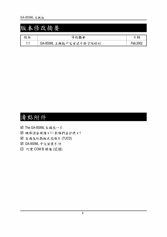
1.1 GA-8SIML Feb.2002
The GA-8SIML x 1 / x 1
(TUCD)GA-8SIML
COM B ( )
5
1.2.3. (CPU RAM)4.5. ATX
PCB

6
GA-8SIML
.......
Micro ATX 22.9 x 24.3Socket478 Intel Micro FC-PGA2 Pentium®4
Intel® Pentium ® 4 (Northwood, 0.13um) Intel Pentium®4 400MHz FSB2nd CPUSiS 650 Host/Memory controllerSiS 961 MuTIOL Media I/O2 184-pin DIMM
DDR333/DDR266/200 SDRAM2 un-buffer DIMM DDR333 2 un-buffer Double-sided
DIMM DDR266/2002.5V DDR DIMM64bit DRAM integrity mode
2GBI/O W83697HF
1 AGP 1X, 2X, 4X 1 CNR3 PCI 33MHz PCI2.2 compliant
IDE 2 IDE bus master (UDMA 33/ATA 66/ATA 100) IDE4 ATAPI
PIO mode 3,4,5,UDMA33/ATA66/ATA100 IDE ATAPI CD-ROM1 (360K,720K,1.2M,1.44M
2.88M bytes)1 Normal/EPP/ECP1 (COMA),1 VGA ,COMB on board4 USB ( x 2, by optional cablex2)1 *1
* PCB 1 .1 .

7
CPUCPUCPU
AC97 CODEC(RealTek ALC201A)Line In/Line Out/Mic In/CD In/Game Port/SPDIF
PS/2 PS/2 PS/2 RTL8100L
1 RJ45 BIOS Award BIOS,2M bit
PS/2 PS/2
AC RecoveryUSB wake up from S3
@BIOS
CPU CPU ,,
, , ;CPU, , , .
8
GA-8SIML
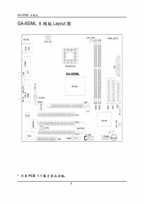
GA-8SIML Layout
* PCB 1 .1 .
CI
DIMM_LED
SPDIF
F_AUDIO*
GA-8SIML
KB_MS
COMA
COMB
LPT
GAME
LINE_
INLINE_
OUT
MIC_
INU
SB/
LAN
AUX_12V
CD_I
N
F_PANEL
BATTERY
SYS
_FAN
SiS 650
SOCKET478
CPU_FAN
ATX
FDD
IDE1
IDE2
AGP
PCI1
PCI2
PCI3 F_USB
DDR2
DDR1
W83
697H
F
FWH
IR
RTL8
100
AC97
CNR
SiS 961
VGA
S_IRQ
Buzzer
9
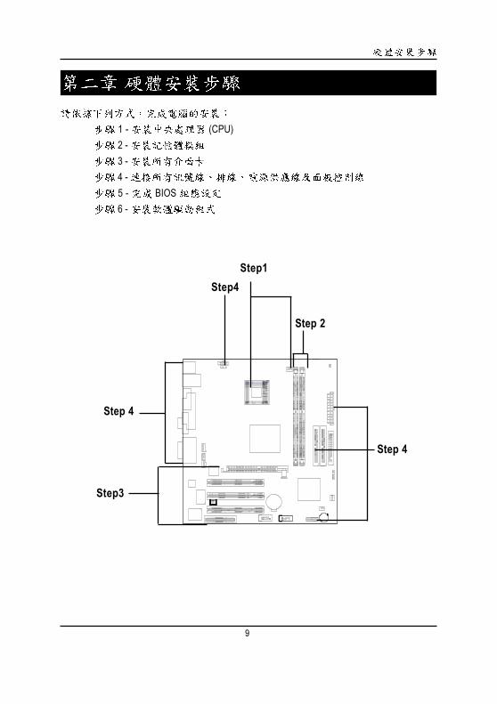
1 - (CPU) 2 - 3 - 4 - 5 - BIOS 6 -
Step 2
Step4
Step3
Step 4
Step 4
Step1

1 0
GA-8SIML
1: (CPU)
1 1
1.90 .
2. ()
.3. ,
.
1
C P U , , ,.
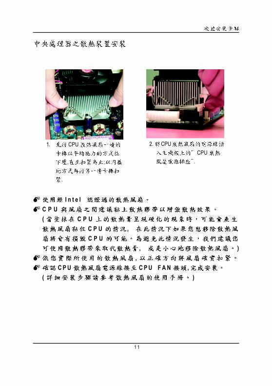
1 1
1. CPU
, ;
.
2. CPUCPU
.
I n t e l C P U( C P U
C P U , C P U
, ),
C P U C P U F A N ,( )
1 2
GA-8SIML
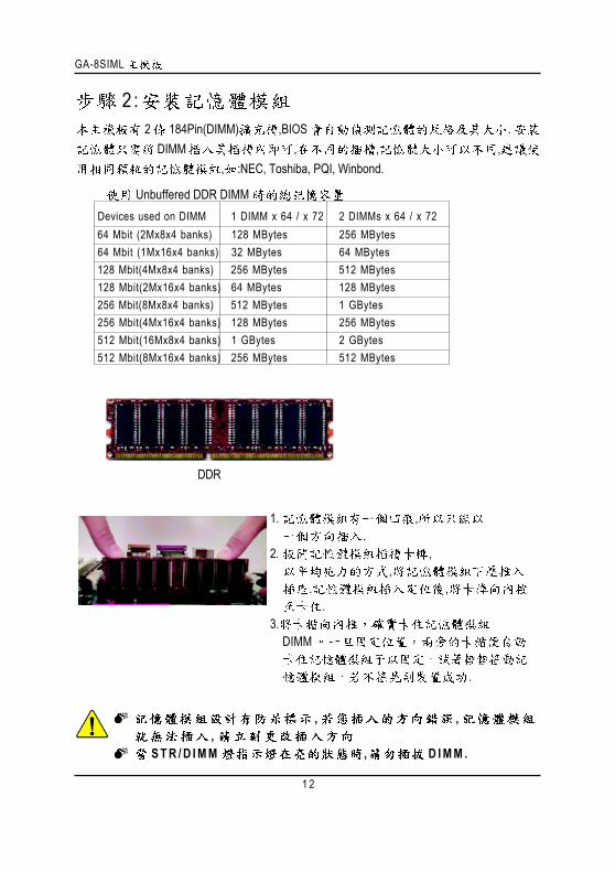
2 :2 184Pin(DIMM) ,BIOS .
DIMM , , ,, :NEC, Toshiba, PQI, Winbond.
Unbuffered DDR DIMM Devices used on DIMM 1 DIMM x 64 / x 72 2 DIMMs x 64 / x 72 64 Mbit (2Mx8x4 banks) 128 MBytes 256 MBytes 64 Mbit (1Mx16x4 banks) 32 MBytes 64 MBytes 128 Mbit(4Mx8x4 banks) 256 MBytes 512 MBytes 128 Mbit(2Mx16x4 banks) 64 MBytes 128 MBytes 256 Mbit(8Mx8x4 banks) 512 MBytes 1 GBytes 256 Mbit(4Mx16x4 banks) 128 MBytes 256 MBytes 512 Mbit(16Mx8x4 banks) 1 GBytes 2 GBytes 512 Mbit(8Mx16x4 banks) 256 MBytes 512 MBytes
, ,,
S T R / D I M M , D I M M .
DDR
1. ,.
2. ,,
. ,.
3.DIMM
.

1 3
DDR DDR(Double Data Rate) PC SDRAM
SDRAM DDROEM
DDR SDRAMSDRAM DDR SDRAM
DDR 2.1GB/s DDRDRAM
PC SDRAM 3.3 volts DDR 2.5 volts DDR
3 :1.2. (
)3.4.5.6.7. BIOS8.
AGP
/ AGP ,. AGP
AGP . AGP

1 4
GA-8SIML
4 :
I/O
PS/2 PS/2
PS/2 (6 pin Female)
PS/2 (6 pin Female)
PS/2PS/2
,
USB USB USBUSB ZIP USB .
USB
USB 0USB 1
LANConnector
1 5
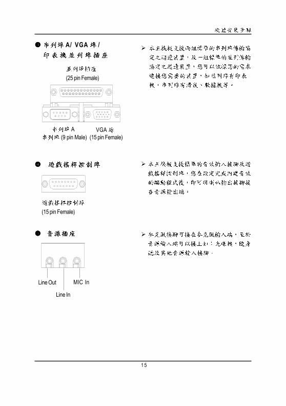
(15 pin Female)
Line In
MIC InLine Out
A/ VGA /
(25 pin Female)
A (9 pin Male)
VGA(15 pin Female)
1 6
GA-8SIML
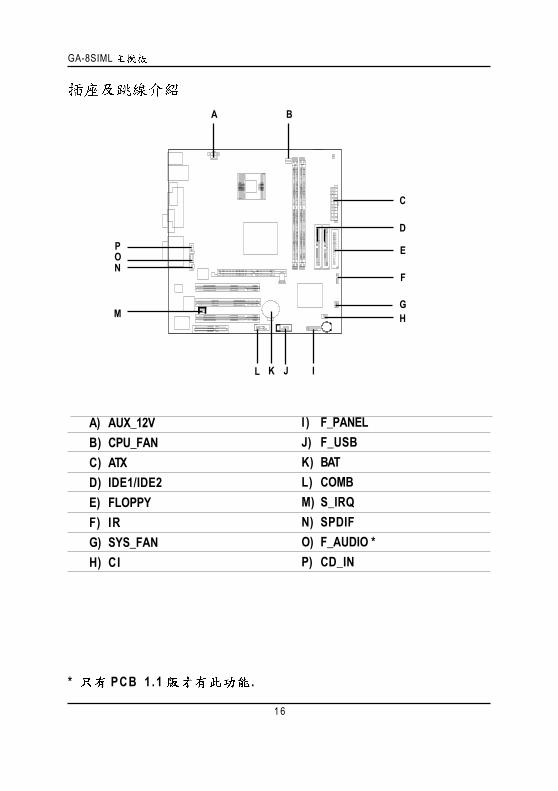
A) AUX_12VB) CPU_FANC) ATXD) IDE1/IDE2E) FLOPPYF) IRG) SYS_FANH) CI
C
E
F
GH
A B
D
IJL
M
I ) F_PANELJ) F_USBK) BATL) COMBM) S_IRQN) SPDIFO) F_AUDIO *P) CD_IN
ON
K
P
* PCB 1 .1 .
1 7
AGPPRO ( +12V12 )
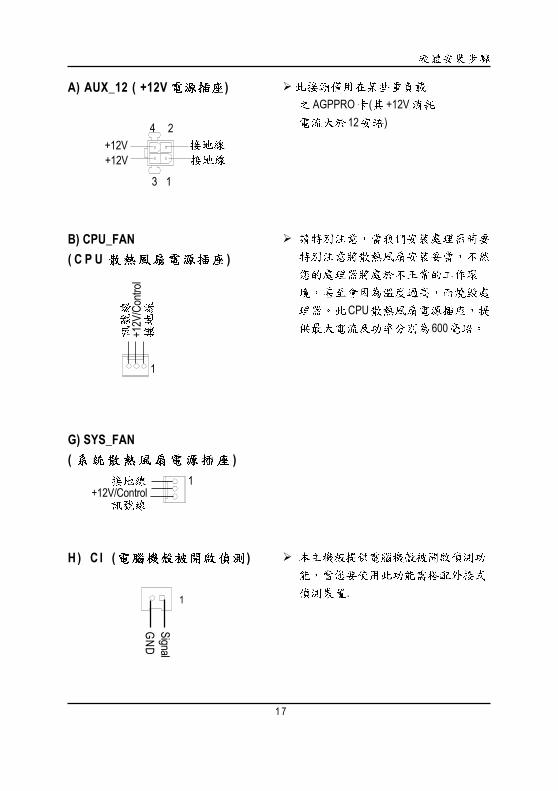
A) AUX_12 ( +12V )
B) CPU_FAN( C P U )
CPU600
+12V/Control1
G) SYS_FAN( )
+12V
/Con
trol
1
4
3
+12V
2
1
+12V
H ) C I ( )
.1
SignalGND
1 8
GA-8SIML
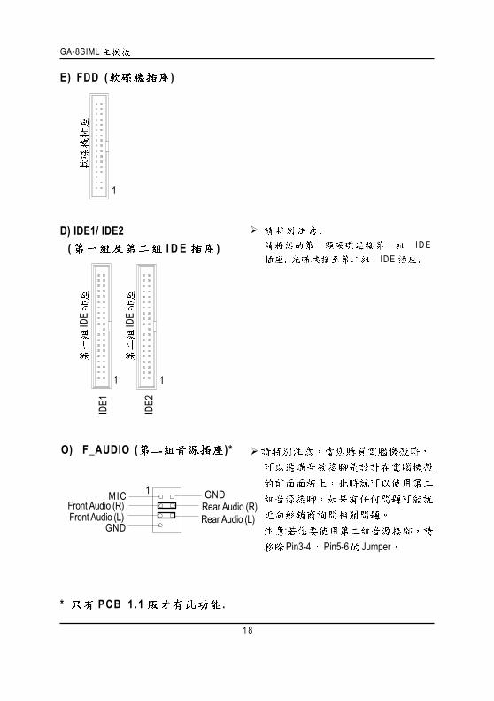
E) FDD ( )
IDE1
1
IDE2
1
1
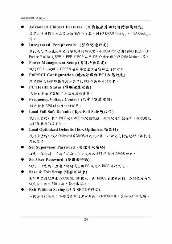
D) IDE1/ IDE2 ( I D E )
IDE
IDE
I D EIDE
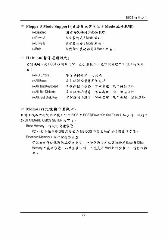
O) F_AUDIO ( )*
:Pin3-4 Pin5-6 Jumper
Front Audio (L)
1 GND
GND
MICRear Audio (R)Rear Audio (L)
Front Audio (R)
* PCB 1 .1 .

1 9
P) CD_IN ( )
1 CD-L
CD-R
F ) I R
VCC(+5V)
IR Data Input
IR Data Output
1
N)SPDIF
VCCSPDIF OutGND
1
J ) F_USB ( )
USB
D3+
USB
D3-
USB
D2-
USB
D2+
USBUSB
USB
1

2 0
GA-8SIML
C) ATX (ATX ) AC (110/220V) ATX
ATXAC (110/
220V)
PS-ON(Soft On/Off)
3.3V3.3V
VCCVCC
+12V5V SB (Stand by +5V)
3.3V
VCCVCC
-12V1
20
-5V
1
L) COM B
M) S_IRQ(For special design, for example: PCMCIA add on card)
1
Signa
lGN
D
K) BAT( )
+

2 1
I) F_PANEL (2x7 Pins )
HD (IDE Hard Disk Active LED) Pin 1: LED anode(+)Pin 2: LED cathode(-)
SPK (Speaker Connector) Pin 1: VCC(+) +5vPin 2- Pin 3: NC Pin 4: Data(-)
RST (Reset Switch)) Open: Normal Operation Close: Reset Hardware System
PD+/PD_G/PD_Y(Power LED) Pin 1: LED anode(+) Pin 2: LED cathode(-)Pin 3: LED cathode(-)
PW (Soft Power Connector) Open: Normal Operation :Close: Power On/Off : /
HD+PD_Y-
2 14
1 13
PD+PW
-PW
+RST-
SPK+
SPK-1
1RST+
HD-
PD_G-

GA-8SIML
2 2
Award BIOS CMOS SETUP
CMOS SETUP CMOS SRAMCMOS SRAM
BIOS POST Power On Self TestDel Award BIOS CMOS SETUP
BIOS
Esc SETUPPage UpPage DownF1F2F3F4F5 ( )F6 Fail-Safe ( )F7 Optimized ( )F8 Dual BIOS/Q-FlashF9F10 CMOS SETUP

BIOS
2 3
Standard CMOS Features ( CMOS )
Advanced BIOS Features ( BIOS )BIOS
....
S E T U PS E T U P
F 1B I O S C M O S S E T U P
< E s c >
(B IOS :FA)F A B I O S ,
http://www.gigabyte.com.tw.C M O S S E T U P ,
, E n t e r
1 :
CMOS Setup Utility-Copyright (C) 1984-2001 Award Software
Standard CMOS Features Frequency/Voltage Control
Advanced BIOS Features Load Fail-Safe Defaults
Advanced Chipset Features Load Optimized Defaults
Integrated Peripherals Set Supervisor Password
Power Management Setup Set User Password
PnP/PCI Configurations Save & Exit Setup
PC Health Status Exit Without Saving
ESC:Quit :Select Item
F8: Dual BIOS/Q-Flash F10:Save & Exit Setup
Time, Date, Hard Disk Type...
GA-8SIML
2 4
Advanced Chipset Features ( )DRAM Timing ISA Clock ....
Integrated Peripherals ( )COM Port IRQ LPT
Port SPP EPP ECP IDE DMA Mode ..Power Management Setup ( )
CPU GREENPnP/PCI Configuration ( PCI )
ISA PnP PCIPC Health Status ( ) ,Frequency/Voltage Control ( / ) CPULoad Fail-Safe Defaults ( Fail-Safe )
BIOS CMOS
Load Optimized Defaults ( Optimized )Optimized CMOS
Set Supervisor Password ( )SETUP CMOS
Set User Password ( )PC BIOS
Save & Exit Setup ( )SETUP BIOS
F10Exit Without Saving ( SETUP )
<ESC>

BIOS
2 5
C M O S
Date(mm:dd:yy) ( )/ /
/ /
(mm) 1 12(dd) 1 28/29/30/31(yy) 1999 2098
CMOS Setup Utility-Copyright (C) 1984-2002 Award Software
Standard CMOS FeaturesDate (mm:dd:yy) Fir, Jan 25 2002 Item HelpTime (hh:mm:ss) 22:31:24 Menu Level
Change the day, month,
IDE Primary Master [None] year and centuryIDE Primary Slave [None]IDE Secondary Master [None] <Week>IDE Secondary Slave [None] Sun. to Sat.
Drive A [1.44M, 3.5 in.] <Month>Drive B [None] Jan. to Dec.Floppy 3 Mode Support [Disabled]
<Day>Halt On [All, But Keyboard] 1 to 31 (or maximum
allowed in the month)Base Memory 640K <Year>Extended Memory 130048K 1999 to 2098Total Memory 131072K
: Move Enter:Select +/-/PU/PD:Value F10:Save ESC:Exit F1:General HelpF5:Previous Values F6:Fail-Safe Defaults F7:Optimized Defaults
2: CMOS

GA-8SIML
2 6
Time(hh:mm:ss) ( )24
13 : 00 : 00 RTC
IDE Primary Master (Slave) / IDE Secondary Master (Slave) ( / )
IDE1 IDE 2CMOS
1 User TYPE CYLS HEADS SECTORSMODE
2 AUTO TYPE MODE AUTO BIOS POSTIDE
CYLS. Number of cylinders( ).HEADS Number of heads( ).PRECOMP Write precomp.LANDZONE Landing zone.SECTORS Number of sectors( ).
"NONE" <Enter>
Drive A / Drive B ( A:/ B: )
None360K, 5.25 in. 5.25 360KB1.2M, 5.25 in. 5.25 1.2MB720K, 3.5 in. 3 720KB1.44M, 3.5 in. 3 1.44MB2.88M, 3.5 in. 3 2.88MB
BIOS
2 7
Floppy 3 Mode Support ( 3 Mode )Disabled 3 ModeDrive A A: 3 ModeDrive B B: 3 ModeBoth A: B: 3 Mode
Halt on( )POST
NO ErrorsAll ErrorsAll, But KeyboardAll, But DisketteAll, But Disk/Key
Memory( )BIOS POST(Power On Self Test)
STANDARD CMOS SETUPBase Memory
PC 640KB MS-DOSExtended Memory
Base OtherMemory Module
GA-8SIML
2 8
BIOS
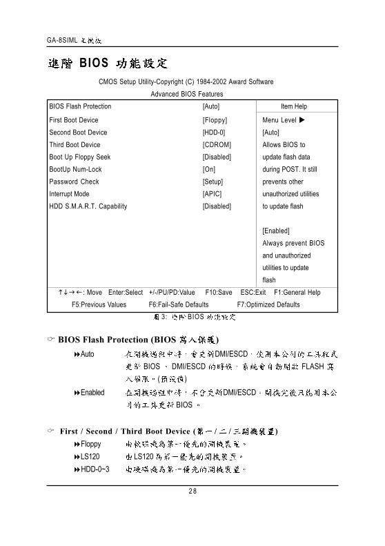
3: BIOS
BIOS Flash Protection (BIOS )Auto DMI/ESCD
BIOS DMI/ESCD FLASH ( )
Enabled DMI/ESCDBIOS
First / Second / Third Boot Device ( / / )FloppyLS120 LS120HDD-0~3
CMOS Setup Utility-Copyright (C) 1984-2002 Award SoftwareAdvanced BIOS Features
BIOS Flash Protection [Auto] Item Help
First Boot Device [Floppy] Menu Level Second Boot Device [HDD-0] [Auto]Third Boot Device [CDROM] Allows BIOS toBoot Up Floppy Seek [Disabled] update flash dataBootUp Num-Lock [On] during POST. It stillPassword Check [Setup] prevents otherInterrupt Mode [APIC] unauthorized utilitiesHDD S.M.A.R.T. Capability [Disabled] to update flash
[Enabled]Always prevent BIOSand unauthorizedutilities to updateflash
: Move Enter:Select +/-/PU/PD:Value F10:Save ESC:Exit F1:General Help F5:Previous Values F6:Fail-Safe Defaults F7:Optimized Defaults
BIOS
2 9
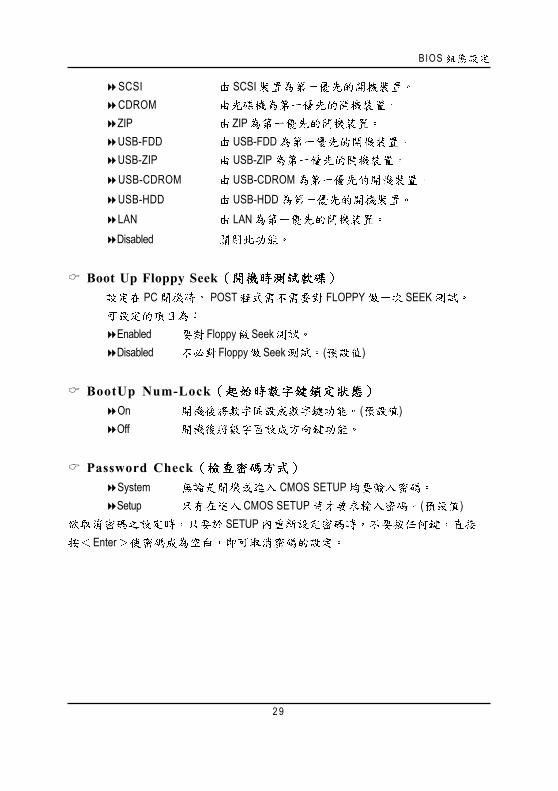
SCSI SCSICDROMZIP ZIPUSB-FDD USB-FDDUSB-ZIP USB-ZIPUSB-CDROM USB-CDROMUSB-HDD USB-HDDLAN LANDisabled
Boot Up Floppy SeekPC POST FLOPPY SEEK
Enabled Floppy SeekDisabled Floppy Seek ( )
BootUp Num-LockOn ( )Off
Password CheckSystem CMOS SETUPSetup CMOS SETUP ( )
SETUPEnter

GA-8SIML
3 0
Interrupt ModeAPIC IOAPIC IRQ ( )PIC IRQ
CPU IOAPIC BIOS IOAPICBIOS APIC
IOAPIC ( Windows NT Windows 2000 Windows XP... ) CPUIOAPIC BIOS PIC
HDD S.M.A.R.T. Capability ( )Enabled S.M.A.R.T. Disabled S.M.A.R.T. ( )

BIOS
3 1
4 :
Top Performance ( ), "Top Performance" "Enabled".
Disabled ( )Enabled
Configure DRAM TimingAuto BIOS ( )Manual Configure DRAM Timing Manual
CMOS Setup Utility-Copyright (C) 1984-2002 Award SoftwareAdvanced Chipset Features
Top Performance [Disabled] Item HelpConfigure DRAM Timing [Auto] Menu Level x CAS Latency Setting [Auto]x DRAM RAS Active Time [6T]x DRAM RAS Precharge Time [3T]x DRAM RAS to CAS Delay [3T]AGP Aperture Size [64MB]
: Move Enter:Select +/-/PU/PD:Value F10:Save ESC:Exit F1:General Help F5:Previous Values F6:Fail-Safe Defaults F7:Optimized Defaults
GA-8SIML
3 2
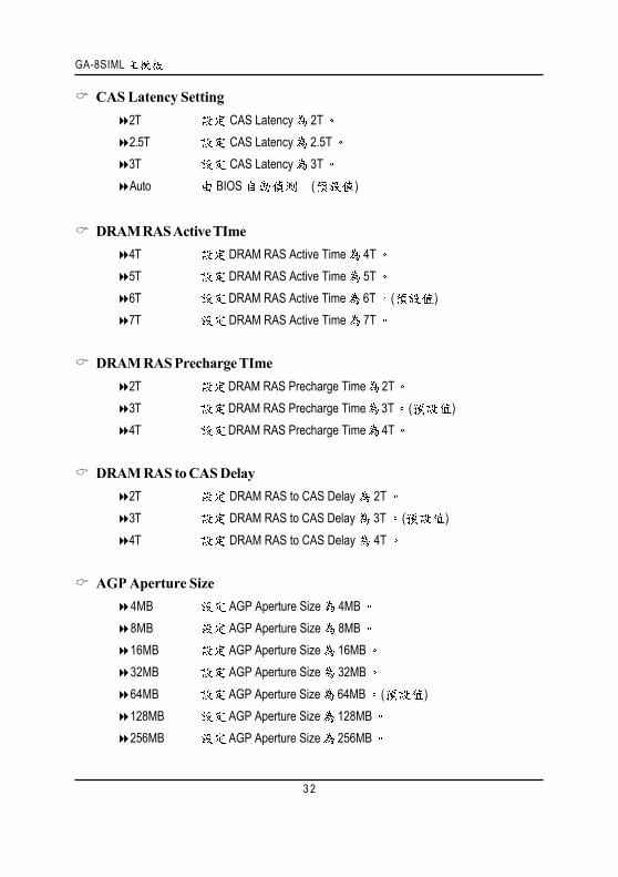
CAS Latency Setting2T CAS Latency 2T2.5T CAS Latency 2.5T3T CAS Latency 3TAuto BIOS ( )
DRAM RAS Active TIme4T DRAM RAS Active Time 4T5T DRAM RAS Active Time 5T6T DRAM RAS Active Time 6T ( )7T DRAM RAS Active Time 7T
DRAM RAS Precharge TIme2T DRAM RAS Precharge Time 2T3T DRAM RAS Precharge Time 3T ( )4T DRAM RAS Precharge Time 4T
DRAM RAS to CAS Delay2T DRAM RAS to CAS Delay 2T3T DRAM RAS to CAS Delay 3T ( )4T DRAM RAS to CAS Delay 4T
AGP Aperture Size4MB AGP Aperture Size 4MB8MB AGP Aperture Size 8MB16MB AGP Aperture Size 16MB32MB AGP Aperture Size 32MB64MB AGP Aperture Size 64MB ( )128MB AGP Aperture Size 128MB256MB AGP Aperture Size 256MB

BIOS
3 3
5 :
CMOS Setup Utility-Copyright (C) 1984-2002 Award SoftwareIntegrated Peripherals
IDE1 Conductor Cable [Auto] Item HelpIDE2 Conductor Cable [Auto] Menu Level On-Chip Primary PCI IDE [Enabled] [Auto]On-Chip Secondary PCI IDE [Enabled] Auto-detect IDEAC97 Audio [Enabled] cable typeAC97 Modem [Enabled]System share Memory Size [32MB] [ATA66/100]USB Controller [Enabled] Set Conductor cableUSB Legacy Support [Disabled] to ATA66/100Onboard LAN Function [Enabled]Init Display First [AGP] [ATA33]Onboard FDC [Enabled] Set Conductor cableOnboard Serial Port A [3F8/IRQ4] to ATA33Onboard Serial Port B [2F8/IRQ3]Serial Port B Mode [Normal]
Onboard Parallel Port [378/IRQ7]Parallel Port Mode [ECP]
EPP Mode Select EPP1.7ECP Mode Use DMA [3]Game Port Address [201]Midi Port Address [330]Midi Port IRQ [10] : Move Enter:Select +/-/PU/PD:Value F10:Save ESC:Exit F1:General Help F5:Previous Values F6:Fail-Safe Defaults F7:Optimized Defaults
GA-8SIML
3 4
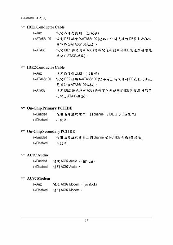
IDE1 Conductor CableAuto ( )ATA66/100 IDE1 ATA66/100 ( IDE
ATA66/100 )ATA33 IDE1 ATA33 ( IDE
ATA33 )
IDE2 Conductor CableAuto ( )ATA66/100 IDE2 ATA66/100 ( IDE
ATA66/100 )ATA33 IDE2 ATA33 ( IDE
ATA33 )
On-Chip Primary PCI IDEEnabled channel IDE .( )Disabled .
On-Chip Secondary PCI IDEEnabled channel PCI IDE .( )Disabled .
AC97 AudioEnabled AC97 Audio ( )Disabled AC97 Audio
AC97 ModemAuto AC97 Modem ( )Disabled AC97 Modem

BIOS
3 5
Share Memory Size4MB/8MB/16MB/32MB/64MB Set onchip VGA shared memory size.(Default Value:32MB)
USB ControllerEnabled USB Controller ( )Disabled USB Controller
USB Legacy Support ( USB )Enabled USBDisabled ( )
Onboard Lan ( )Enabled ( )Disabled
Init Display FirstAGP AGP ( )PCI PCI
Onboard FDCEnabled ( )Disabled
Onboard Serial Port A AAuto BIOS3F8/IRQ4 A COM 1 3F8 ( )2F8/IRQ3 A COM 2 2F83E8/IRQ4 A COM 3 3E82E8/IRQ3 A COM 4 2E8Disabled A
GA-8SIML
3 6
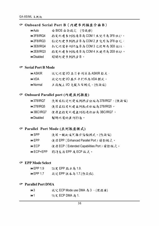
Onboard Serial Port B BAuto BIOS ( )3F8/IRQ4 B COM 1 3F82F8/IRQ3 B COM 2 2F83E8/IRQ4 B COM 3 3E82E8/IRQ3 B COM 4 2E8Disabled B
Serial Port B ModeASKIR I/O ASKIRIrDA I/O IrDANormal I/O ( )
Onboard Parallel port ( )378/IRQ7 378/IRQ7 ( )278/IRQ5 278/IRQ53BC/IRQ7 3BC/IRQ7Disabled
Parallel Port Mode ( )SPP ( )EPP EPP Enhanced Parallel PortECP ECP Extended Capabilities PortECP+EPP EPP ECP
EPP Mode SelectEPP 1.9 EPP 1.9.EPP 1.7 EPP 1.7.( ).
Parallel Port DMA3 ECP Mode use DMA 3 ( )1 ECP DMA 1.
BIOS
3 7
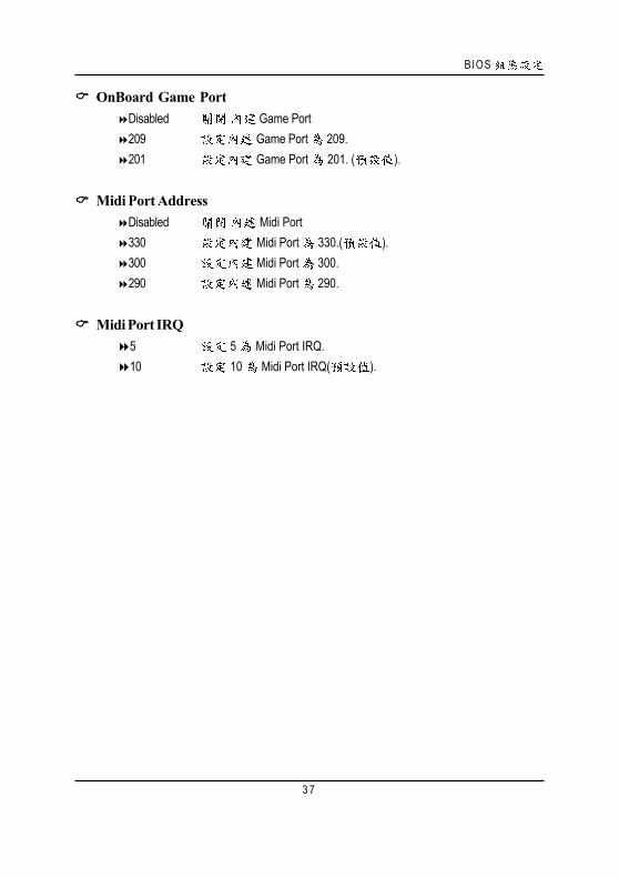
OnBoard Game PortDisabled Game Port209 Game Port 209.201 Game Port 201. ( ).
Midi Port AddressDisabled Midi Port330 Midi Port 330.( ).300 Midi Port 300.290 Midi Port 290.
Midi Port IRQ5 5 Midi Port IRQ.10 10 Midi Port IRQ( ).
GA-8SIML
3 8
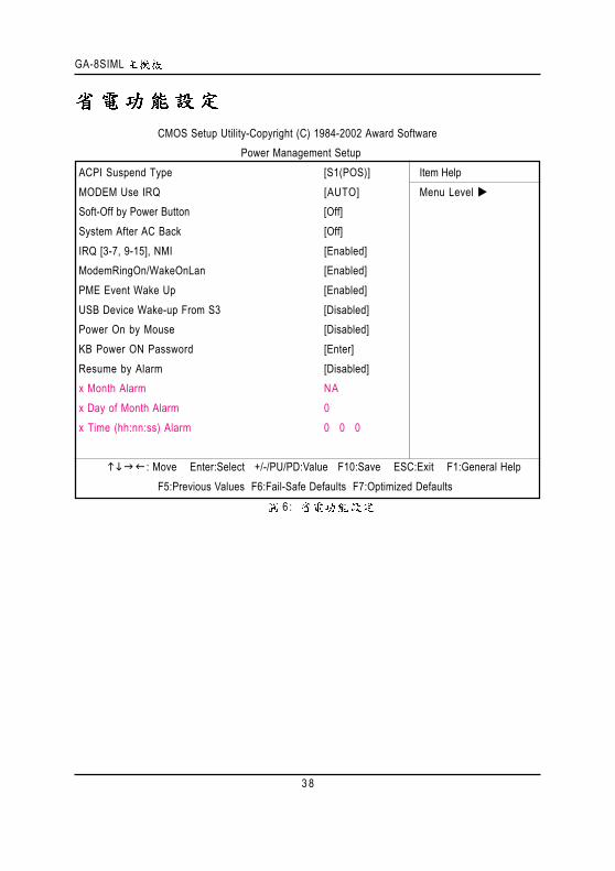
6 :
CMOS Setup Utility-Copyright (C) 1984-2002 Award SoftwarePower Management Setup
ACPI Suspend Type [S1(POS)] Item HelpMODEM Use IRQ [AUTO] Menu Level Soft-Off by Power Button [Off]System After AC Back [Off]IRQ [3-7, 9-15], NMI [Enabled]ModemRingOn/WakeOnLan [Enabled]PME Event Wake Up [Enabled]USB Device Wake-up From S3 [Disabled]Power On by Mouse [Disabled]KB Power ON Password [Enter]Resume by Alarm [Disabled]x Month Alarm NAx Day of Month Alarm 0x Time (hh:nn:ss) Alarm 0 0 0
: Move Enter:Select +/-/PU/PD:Value F10:Save ESC:Exit F1:General HelpF5:Previous Values F6:Fail-Safe Defaults F7:Optimized Defaults
BIOS
3 9
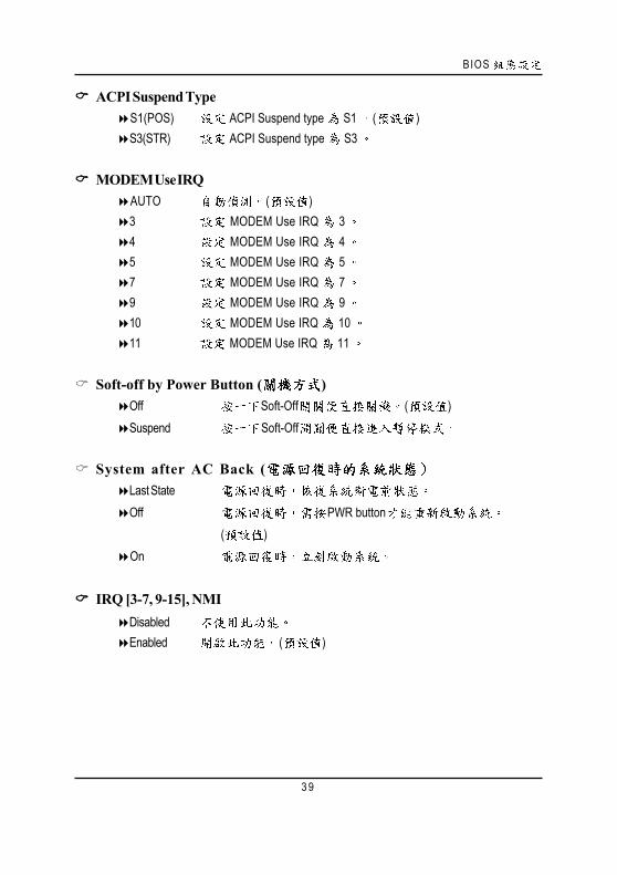
ACPI Suspend TypeS1(POS) ACPI Suspend type S1 ( )S3(STR) ACPI Suspend type S3
MODEM Use IRQAUTO ( )3 MODEM Use IRQ 34 MODEM Use IRQ 45 MODEM Use IRQ 57 MODEM Use IRQ 79 MODEM Use IRQ 910 MODEM Use IRQ 1011 MODEM Use IRQ 11
Soft-off by Power Button ( )Off Soft-Off ( )Suspend Soft-Off
System after AC Back (Last StateOff PWR button
( )On
IRQ [3-7, 9-15], NMIDisabledEnabled ( )
GA-8SIML
4 0
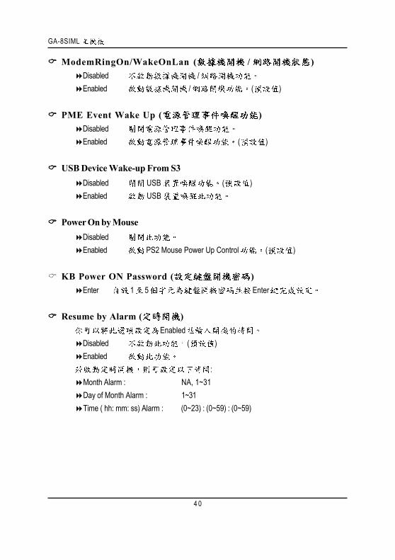
ModemRingOn/WakeOnLan ( / )Disabled /Enabled / ( )
PME Event Wake Up ( )DisabledEnabled ( )
USB Device Wake-up From S3Disabled USB ( )Enabled USB
Power On by MouseDisabledEnabled PS2 Mouse Power Up Control ( )
KB Power ON Password ( )Enter 1 5 Enter
Resume by Alarm ( )Enabled
Disabled ( )Enabled
:Month Alarm : NA, 1~31Day of Month Alarm : 1~31Time ( hh: mm: ss) Alarm : (0~23) : (0~59) : (0~59)
BIOS
4 1
P C I
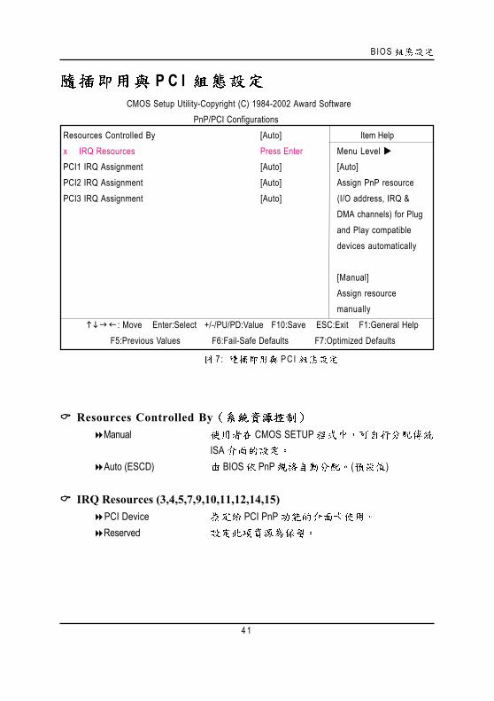
7 : PC I
Resources Controlled ByManual CMOS SETUP
ISAAuto (ESCD) BIOS PnP ( )
IRQ Resources (3,4,5,7,9,10,11,12,14,15)PCI Device PCI PnPReserved
CMOS Setup Utility-Copyright (C) 1984-2002 Award SoftwarePnP/PCI Configurations
Resources Controlled By [Auto] Item Helpx IRQ Resources Press Enter Menu Level PCI1 IRQ Assignment [Auto] [Auto]PCI2 IRQ Assignment [Auto] Assign PnP resourcePCI3 IRQ Assignment [Auto] (I/O address, IRQ &
DMA channels) for Plugand Play compatibledevices automatically
[Manual]Assign resourcemanually
: Move Enter:Select +/-/PU/PD:Value F10:Save ESC:Exit F1:General Help F5:Previous Values F6:Fail-Safe Defaults F7:Optimized Defaults
GA-8SIML
4 2
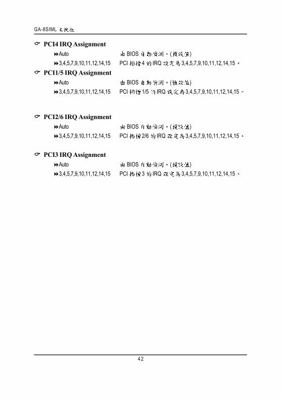
PCI2/6 IRQ AssignmentAuto BIOS ( )3,4,5,7,9,10,11,12,14,15 PCI 2/6 IRQ 3,4,5,7,9,10,11,12,14,15
PCI3 IRQ AssignmentAuto BIOS ( )3,4,5,7,9,10,11,12,14,15 PCI 3 IRQ 3,4,5,7,9,10,11,12,14,15
PCI4 IRQ AssignmentAuto BIOS ( )3,4,5,7,9,10,11,12,14,15 PCI 4 IRQ 3,4,5,7,9,10,11,12,14,15
PCI1/5 IRQ AssignmentAuto BIOS ( )3,4,5,7,9,10,11,12,14,15 PCI 1/5 IRQ 3,4,5,7,9,10,11,12,14,15
BIOS
4 3
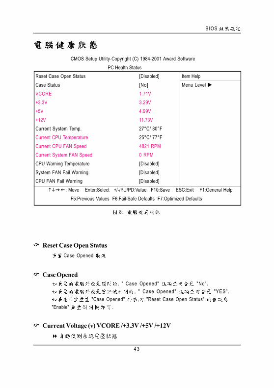
8 :
Reset Case Open StatusCase Opened
Case Opened, " Case Opened" "No".
, " Case Opened" "YES". "Case Opened" , "Reset Case Open Status"
"Enable" .
Current Voltage (v) VCORE /+3.3V /+5V /+12V
CMOS Setup Utility-Copyright (C) 1984-2001 Award SoftwarePC Health Status
Reset Case Open Status [Disabled] Item HelpCase Status [No] Menu Level VCORE 1.71V+3.3V 3.29V+5V 4.99V+12V 11.73VCurrent System Temp. 27°C/ 80°FCurrent CPU Temperature 25°C/ 77°FCurrent CPU FAN Speed 4821 RPMCurrent System FAN Speed 0 RPMCPU Warning Temperature [Disabled]System FAN Fail Warning [Disabled]CPU FAN Fail Warning [Disabled] : Move Enter:Select +/-/PU/PD:Value F10:Save ESC:Exit F1:General Help
F5:Previous Values F6:Fail-Safe Defaults F7:Optimized Defaults

GA-8SIML
4 4
Current CPU / SYSTEM TemperatureCPU / .
CPU FAN / System FAN Speed (RPM).
CPU Warning Temperature60 oC / 140 oF CPU 60 oC / 140 oF.70 oC / 158 oF CPU 70 oC / 158 oF.80 oC / 176 oF CPU 80 oC / 176 oF.90 oC / 194 oF CPU 90 oC / 194 oF.Disabled .( )
Fan Fail Alarm (CPU/System )Enabled CPU / Power / System .Disabled CPU / Power / System . ( )
BIOS
4 5
/
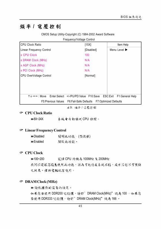
9 : /
CPU Clock Ratio8X~24X CPU
Linear Frequency ControlDisabled ( )Enabled
CPU Clock100~200 CPU 100MHz 200MHz
DRAM Clock (MHz)
DDR200 DRAM Clock(MHz) 100DDR333 DRAM Clock(MHz) 166
CMOS Setup Utility-Copyright (C) 1984-2002 Award SoftwareFrequency/Voltage Control
CPU Clock Ratio [15X] Item HelpLinear Frequency Control [Disabled] Menu Level x CPU Clock 100x DRAM Clock (MHz) N/Ax AGP Clock (MHz) N/Ax PCI Clock (MHz) N/ACPU OverVoltage Control [Normal]
: Move Enter:Select +/-/PU/PD:Value F10:Save ESC:Exit F1:General HelpF5:Previous Values F6:Fail-Safe Defaults F7:Optimized Defaults

GA-8SIML
4 6
AGP Clock (MHz)
PCI Clock (MHz)
CPU OverVoltage Control ( )0.025V
( Normal)
BIOS
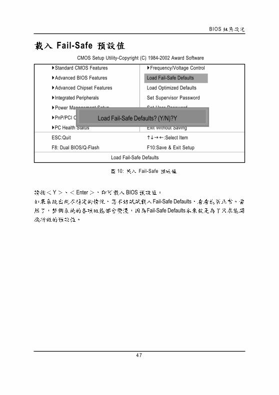
4 7
Fail-Safe
10: Fail-Safe
Y Enter BIOS Fail-Safe Defaults
Fail-Safe Defaults
CMOS Setup Utility-Copyright (C) 1984-2002 Award Software
Standard CMOS Features Frequency/Voltage Control
Advanced BIOS Features Load Fail-Safe Defaults
Advanced Chipset Features Load Optimized Defaults
Integrated Peripherals Set Supervisor Password
Power Management Setup Set User Password
PnP/PCI Configurations Save & Exit Setup
PC Health Status Exit Without Saving
ESC:Quit :Select Item
F8: Dual BIOS/Q-Flash F10:Save & Exit Setup
Load Fail-Safe Defaults
Load Fail-Safe Defaults? (Y/N)?Y
GA-8SIML
4 8
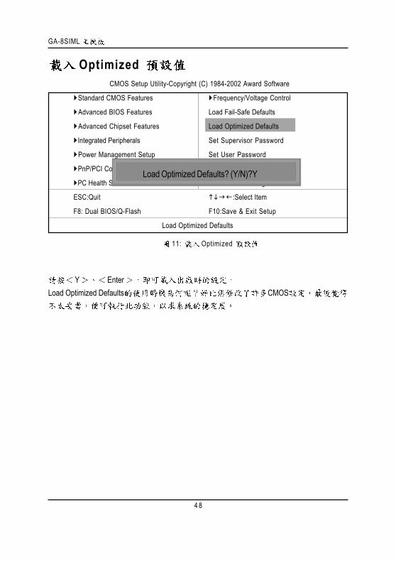
Optimized
Y EnterLoad Optimized Defaults CMOS
11: Optimized
CMOS Setup Utility-Copyright (C) 1984-2002 Award Software
Standard CMOS Features Frequency/Voltage Control
Advanced BIOS Features Load Fail-Safe Defaults
Advanced Chipset Features Load Optimized Defaults
Integrated Peripherals Set Supervisor Password
Power Management Setup Set User Password
PnP/PCI Configurations Save & Exit Setup
PC Health Status Exit Without Saving
ESC:Quit :Select Item
F8: Dual BIOS/Q-Flash F10:Save & Exit Setup
Load Optimized Defaults
Load Optimized Defaults? (Y/N)?Y

BIOS
4 9
(Supervisor)/ (User)
12: (Supervisor)/ (User)
8 Enter BIOS
Enter BIOSPASSWORD DISABLED
SUPERVISOR Supervisor Advanced BIOS Features Password
Check SETUP CMOS SETUP Supervisor
USER User Advanced BIOS Features Password Check
SYSTEM User SupervisorCMOS SETUP USER Password
BIOS Supervisor CMOS SETUP
CMOS Setup Utility-Copyright (C) 1984-2002 Award Software
Standard CMOS Features Frequency/Voltage Control
Advanced BIOS Features Load Fail-Safe Defaults
Advanced Chipset Features Load Optimized Defaults
Integrated Peripherals Set Supervisor Password
Power Management Setup Set User Password
PnP/PCI Configurations Save & Exit Setup
PC Health Status Exit Without Saving
ESC:Quit :Select Item
F8: Dual BIOS/Q-Flash F10:Save & Exit Setup
Change/Set/Disable Password
Enter Password:

GA-8SIML
5 0
S E T U P
Y Enter RTC CMOS Setup UtilityN Esc
13: SETUP
CMOS Setup Utility-Copyright (C) 1984-2002 Award Software
Standard CMOS Features Frequency/Voltage Control
Advanced BIOS Features Load Fail-Safe Defaults
Advanced Chipset Features Load Optimized Defaults
Integrated Peripherals Set Supervisor Password
Power Management Setup Set User Password
PnP/PCI Configurations Save & Exit Setup
PC Health Status Exit Without Saving
ESC:Quit :Select Item
F8: Dual BIOS/Q-Flash F10:Save & Exit Setup
Save Data to CMOS
Save to CMOS and EXIT (Y/N)? Y

BIOS
5 1
S E T U P
Y Enter Setup Utility N Esc
1 4 : S E T U P
CMOS Setup Utility-Copyright (C) 1984-2002 Award Software
Standard CMOS Features Frequency/Voltage Control
Advanced BIOS Features Load Fail-Safe Defaults
Advanced Chipset Features Load Optimized Defaults
Integrated Peripherals Set Supervisor Password
Power Management Setup Set User Password
PnP/PCI Configurations Save & Exit Setup
PC Health Status Exit Without Saving
ESC:Quit :Select Item
F8: Dual BIOS/Q-Flash F10:Save & Exit Setup
Abandon all Data
Quit Without Saving (Y/N)? N
GA-8SIML
5 2
Revision History
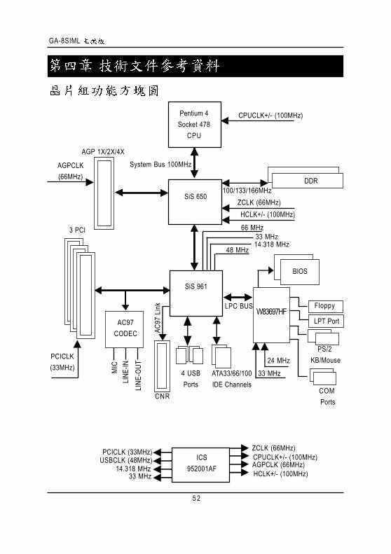
Pentium 4Socket 478
CPU
SiS 650
AC97CODEC
SiS 961
CPUCLK+/- (100MHz)
System Bus 100MHz
DDR100/133/166MHz
ZCLK (66MHz)HCLK+/- (100MHz)
66 MHz33 MHz14.318 MHz
48 MHz
24 MHz33 MHz
LPC BUS
AGP 1X/2X/4X
AGPCLK(66MHz)
3 PCI
PCICLK(33MHz)
AC97
Link
MIC
LINE
-INLI
NE-O
UT
4 USBPorts
ATA33/66/100IDE Channels
Floppy
LPT Port
PS/2 KB/Mouse
COM Ports
CNR
ICS952001AF
ZCLK (66MHz)CPUCLK+/- (100MHz)AGPCLK (66MHz)HCLK+/- (100MHz)
PCICLK (33MHz)USBCLK (48MHz)
14.318 MHz33 MHz
BIOS
W83697HF

5 3
@ BIOSTM
@BIOSTM BIOS
EasyTune IIITM
DOS BIOS Windows@BIOSTM BIOS
@BIOSTM BIOS
@BIOSTM Internet BIOS BIOSWindows BIOS !
@BIOSTM BIOS
GA-8SIML
5 4
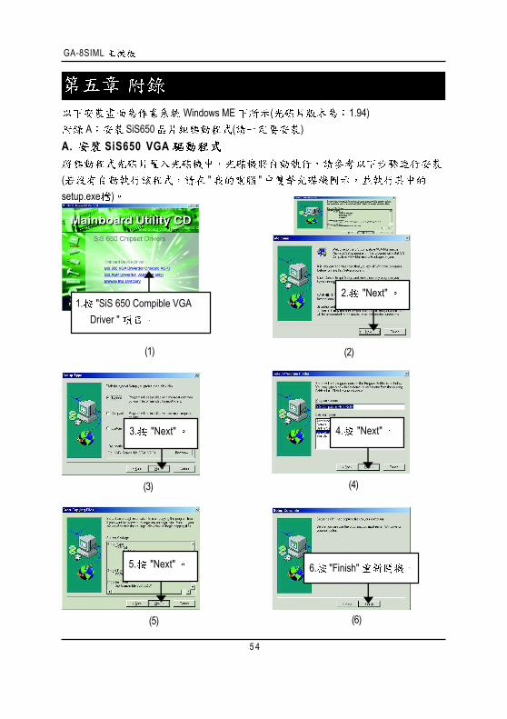
Revision History Windows ME ( 1.94)
A SiS650 ( )A. SiS650 VGA
( " "setup.exe )
2. "Next"
3. "Next"
6. "Finish"
(4)(3)
(2)(1)
(6)(5)
4. "Next"
1. "SiS 650 Compible VGADriver "
5. "Next"

5 5
B: AGP
( " "setup.exe )
(4)(3)
(2)(1)
1. "SiS AGP Driver .
3. "Next".2. "Next".
4. "Finish" .
(6)(5)
GA-8SIML
5 6
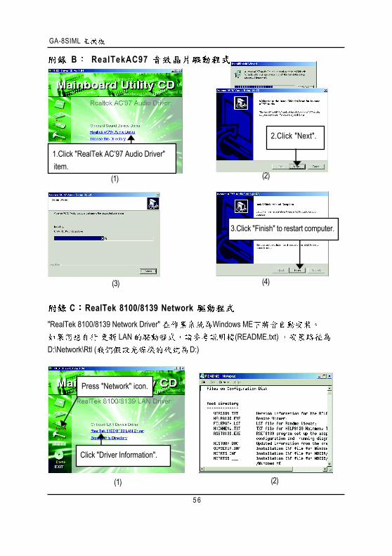
Revision History B RealTekAC97
(1)
1.Click "RealTek AC’97 Audio Driver" item.
(2)
(3)
3.Click "Finish" to restart computer.
(4)
2.Click "Next".
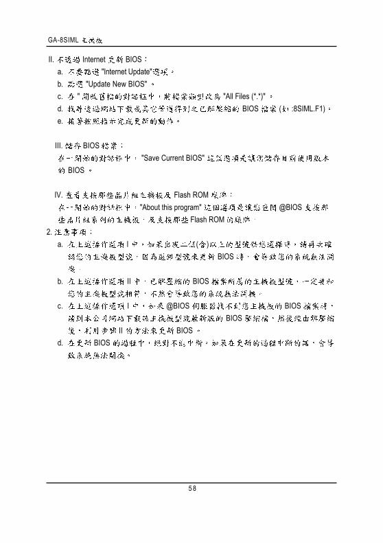
Revision History C RealTek 8100/8139 Network "RealTek 8100/8139 Network Driver" Windows ME
LAN (README.txt) D:\Network\Rtl ( D:)
(1) (2)
Press "Network" icon.
Click "Driver Information".

5 7
C BIOSBIOS
OS Win9X @BIOS
1. I. Internet BIOS
a. "Internet Update"b. "Update New BIOS"c. @BIOS ( "Gigabyte @BIOS server 1 in Taiwan"
"Gigabyte @BIOS server 2 in Taiwan")d.e. BIOS
(3)
(2)
" Tools"
(1)
1. "Gigabyte Utilities"
2. "@BIOS Writer Utility v1.08m"
" "
GA-8SIML
5 8
II. Internet BIOSa. "Internet Update"b. "Update New BIOS"c. " "All Files (*.*)"d. BIOS ( :8SIML.F1)e.
III. BIOS"Save Current BIOS"
BIOS
IV. Flash ROM "About this program" @BIOS
Flash ROM2.
a. I ( ) BIOS
b. II BIOS
c. I @BIOS BIOS BIOS
II BIOSd. BIOS
5 9
GA-7VTX Flash841 BIOSDOS BIOS
Flash BIOS ( )
(1) "BIOS Feature Setup" "BIOS Flash Protection" Auto28
(2) Winzippkunzip winzip
: http://shareware.cnet.com( ) DOS ( Windows 98 )
Windows ME/2000 DOS(1) ( " ") "
" "3.5 (A)" " "
GA-8SIML
6 0
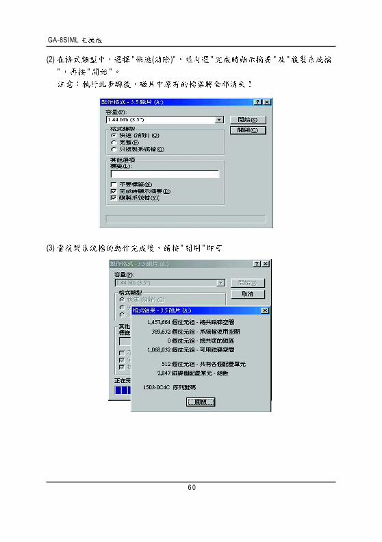
(2) " ( )" " " "" " "
(3) " "
6 1
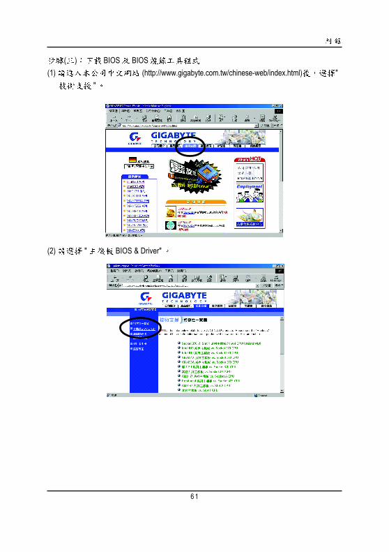
( ) BIOS BIOS(1) (http://www.gigabyte.com.tw/chinese-web/index.html) "
"
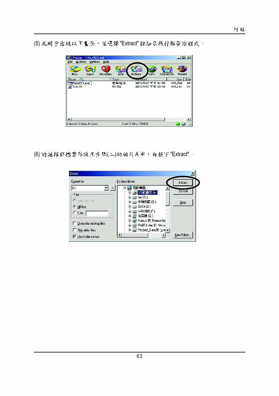
(2) " BIOS & Driver"

GA-8SIML
6 2
(3) GA-7VTX BIOS
(4) ( F4) "" " "
6 3
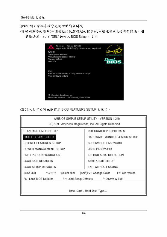
(5) "Extract"
(6) ( ) A "Extract"
GA-8SIML
6 4
( )(1) ( ) A
"DEL" BIOS Setup
(2) BIOS FEATUERS SETUP
7VTX F1Check System Health OKAMD-Athlon(tm)Processor-900MHzChecking NVRAM...262144KB
Wait...Press F1 to enter Dual BIOS Utility. Press ESC to quitPress any key to contiune
( C ) American Megatrends Inc.,63-0001-001199-00101111-071595-VIA_K7-GA7VTX1-F
American Release:09/16/99Megatrends AMIBIOS (C) 1999 American Megatrend
AMIBIOS SIMPLE SETUP UTILITY - VERSION 1.24b(C) 1999 American Megatrends, Inc. All Rights Reserved
STANDARD CMOS SETUP INTEGRATED PERIPHERALS
BIOS FEATURES SETUP HARDWARE MONITOR & MISC SETUP
CHIPSET FEATURES SETUP SUPERVISOR PASSWORD
POWER MANAGEMENT SETUP USER PASSWORD
PNP / PCI CONFIGURATION IDE HDD AUTO DETECTION
LOAD BIOS DEFAULTS SAVE & EXIT SETUP
LOAD SETUP DEFAULTS EXIT WITHOUT SAVING
ESC: Quit : Select Item (Shift)F2 : Change Color F5: Old Values
F6: Load BIOS Defaults F7: Load Setup Defaults F10:Save & Exit
Time, Date , Hard Disk Type…

6 5
(3) "Enter" "BIOS FEATUERS SETUP" "1st BootDevice" "Page Up" "Page Down" "Floppy"
(4) "ESC" "SAVE & EXIT SETUP" "Enter""Y" "Enter"
AMIBIOS SETUP - BIOS FEATURES SETUP( C ) 2001 American Megatrends, Inc. All Rights Reserved
1st Boot Device : Floppy2nd Boot Device : IDE-03rd Boot Device : CDROMS.M.A.R.T. for Hard Disks : DisabledBootUp Num-Lock : On ESC: Quit : Select ItemFloppy Drive Seek : Disabled F1 : Help PU/PD/+/- : ModifyPassword Check : Setup F5 : Old Values (Shift)F2: Color
F6 : Load BIOS DefaultsF7 : Load Setup Defaults
AMIBIOS SIMPLE SETUP UTILITY - VERSION 1.24b(C) 2001 American Megatrends, Inc. All Rights Reserved
STANDARD CMOS SETUP INTEGRATED PERIPHERALS
BIOS FEATURES SETUP HARDWARE MONITOR & MISC SETUP
CHIPSET FEATURES SETUP SUPERVISOR PASSWORD
POWER MANAGEMENT SETUP USER PASSWORD
PNP / PCI CONFIGURATION IDE HDD AUTO DETECTION
LOAD BIOS DEFAULTS SAVE & EXIT SETUP
LOAD SETUP DEFAULTS EXIT WITHOUT SAVING
ESC: Quit : Select Item (Shift)F2 : Change Color F5: Old Values
F6: Load BIOS Defaults F7: Load Setup Defaults F10:Save & Exit
Save Data to CMOS & Exit SETUP
Save to CMOS and EXIT (Y/N)? Y

GA-8SIML
6 6
( ) BIOS(1) A:\> dir/w "Enter"
A:\> "BIOS " "BIOS ""Flash841 7VTX.F4" "Enter"
(2) [Enter] Load[Drive:\Path\Filename] [Enter]
Starting Windows 98Microsoft(R) Windows98 © Copyright Microsoft Corp 1981-1999
A:\> dir/w Volume in drive A has no labelVolume Serial Number is 16EB-353DDirectory of A:\COMMAND.COM 7VTX.F4 FLASH841.EXE 3 file(s) 838,954 bytes 0 dir(s) 324,608 bytes free
A:\> Flash841 7VTX.F4
6 7
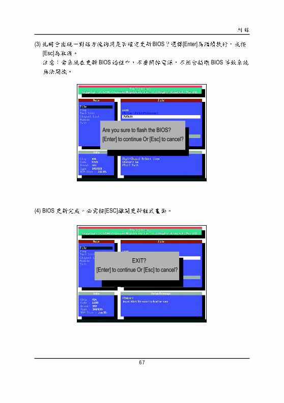
(3) BIOS [Enter][Esc]
BIOS BIOS
(4) BIOS [ESC]
Are you sure to flash the BIOS?[Enter] to continue Or [Esc] to cancel?
EXIT?[Enter] to continue Or [Esc] to cancel?
GA-8SIML
6 8
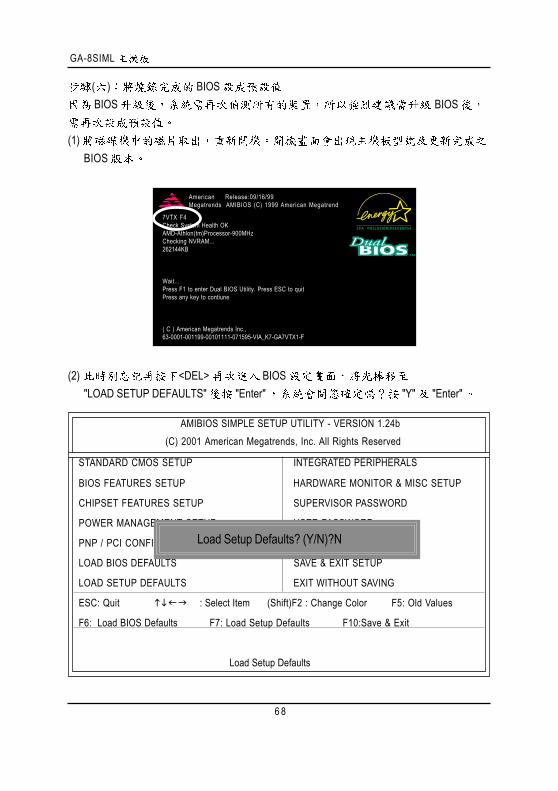
( ) BIOSBIOS BIOS
(1) BIOS
(2) <DEL> BIOS "LOAD SETUP DEFAULTS" "Enter" "Y" "Enter"
7VTX F4Check System Health OKAMD-Athlon(tm)Processor-900MHzChecking NVRAM...262144KB
Wait...Press F1 to enter Dual BIOS Utility. Press ESC to quitPress any key to contiune
( C ) American Megatrends Inc.,63-0001-001199-00101111-071595-VIA_K7-GA7VTX1-F
American Release:09/16/99Megatrends AMIBIOS (C) 1999 American Megatrend
AMIBIOS SIMPLE SETUP UTILITY - VERSION 1.24b(C) 2001 American Megatrends, Inc. All Rights Reserved
STANDARD CMOS SETUP INTEGRATED PERIPHERALS
BIOS FEATURES SETUP HARDWARE MONITOR & MISC SETUP
CHIPSET FEATURES SETUP SUPERVISOR PASSWORD
POWER MANAGEMENT SETUP USER PASSWORD
PNP / PCI CONFIGURATION IDE HDD AUTO DETECTION
LOAD BIOS DEFAULTS SAVE & EXIT SETUP
LOAD SETUP DEFAULTS EXIT WITHOUT SAVING
ESC: Quit : Select Item (Shift)F2 : Change Color F5: Old Values
F6: Load BIOS Defaults F7: Load Setup Defaults F10:Save & Exit
Load Setup Defaults
Load Setup Defaults? (Y/N)?N

6 9
(3) "SAVE & EXIT SETUP" "Enter""Y" "Enter"
(4) BIOS
AMIBIOS SIMPLE SETUP UTILITY - VERSION 1.24b(C) 2001 American Megatrends, Inc. All Rights Reserved
STANDARD CMOS SETUP INTEGRATED PERIPHERALS
BIOS FEATURES SETUP HARDWARE MONITOR & MISC SETUP
CHIPSET FEATURES SETUP SUPERVISOR PASSWORD
POWER MANAGEMENT SETUP USER PASSWORD
PNP / PCI CONFIGURATION IDE HDD AUTO DETECTION
LOAD BIOS DEFAULTS SAVE & EXIT SETUP
LOAD SETUP DEFAULTS EXIT WITHOUT SAVING
ESC: Quit : Select Item (Shift)F2 : Change Color F5: Old Values
F6: Load BIOS Defaults F7: Load Setup Defaults F10:Save & Exit
Save Data to CMOS & Exit SETUP
Save to CMOS and EXIT (Y/N)? Y
GA-8SIML
7 0
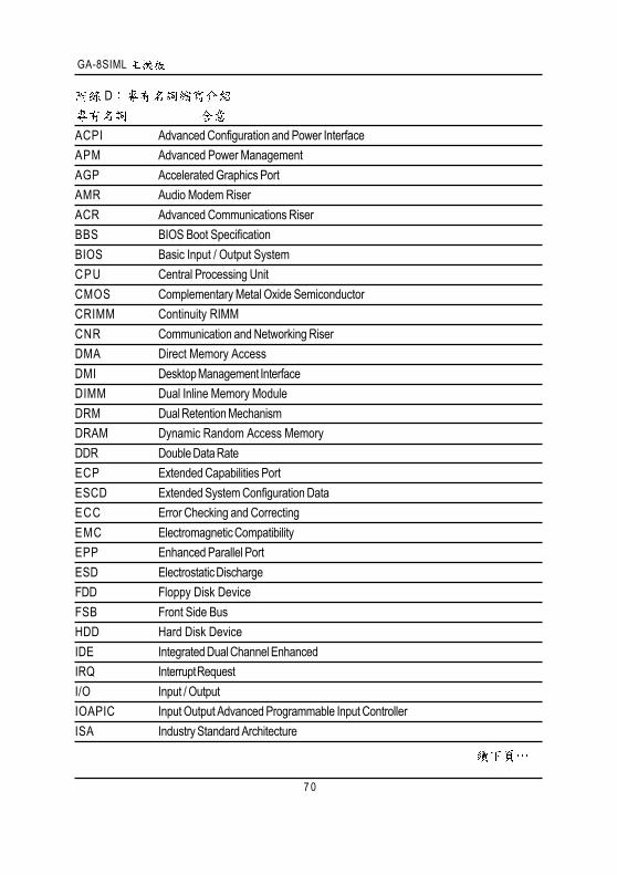
D
ACPI Advanced Configuration and Power InterfaceAPM Advanced Power ManagementAGP Accelerated Graphics PortAMR Audio Modem RiserACR Advanced Communications RiserBBS BIOS Boot SpecificationBIOS Basic Input / Output SystemCPU Central Processing UnitCMOS Complementary Metal Oxide SemiconductorCRIMM Continuity RIMMCNR Communication and Networking RiserDMA Direct Memory AccessDMI Desktop Management InterfaceDIMM Dual Inline Memory ModuleDRM Dual Retention MechanismDRAM Dynamic Random Access MemoryDDR Double Data RateECP Extended Capabilities PortESCD Extended System Configuration DataECC Error Checking and CorrectingEMC Electromagnetic CompatibilityEPP Enhanced Parallel PortESD Electrostatic DischargeFDD Floppy Disk DeviceFSB Front Side BusHDD Hard Disk DeviceIDE Integrated Dual Channel EnhancedIRQ Interrupt RequestI/O Input / OutputIOAPIC Input Output Advanced Programmable Input ControllerISA Industry Standard Architecture
7 1
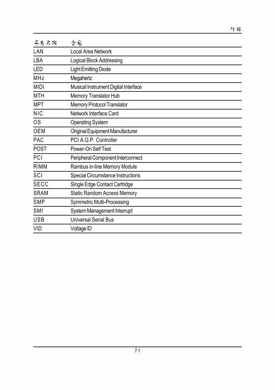
LAN Local Area NetworkLBA Logical Block AddressingLED Light Emitting DiodeMHz MegahertzMIDI Musical Instrument Digital InterfaceMTH Memory Translator HubMPT Memory Protocol TranslatorNIC Network Interface CardOS Operating SystemOEM Original Equipment ManufacturerPAC PCI A.G.P. ControllerPOST Power-On Self TestPCI Peripheral Component InterconnectRIMM Rambus in-line Memory ModuleSCI Special Circumstance InstructionsSECC Single Edge Contact CartridgeSRAM Static Random Access MemorySMP Symmetric Multi-ProcessingSMI System Management InterruptUSB Universal Serial BusVID Voltage ID

GA-8SIML
7 2
/
LotBIOS /
(CPU)(RAM)(Video)(Audio)
(HDD)CD-ROM /DVD-ROM
(Modem)
(Network)AMR / CNR
: