Embed Size (px)
Citation preview
ii
DECLARATION
I declare that this final year project report entitled “Study a Pneumatic Telescopic
Cylinder Arm Operation for Variable Load Application” is my own work except as cited
in the reference.
Signature : …………………………………
Name : Mohd Fauzy B. Khamis
I/C No. : 870716-15-5067
Metric No. : B040610086
Date : 7 April 2010
iii
ACKNOWLEDGEMENT
First of all, the author would like to express his gratitude to Allah S.W.T for
bless and guidance that allowing the author to finish up this Projek Sarjana Muda (PSM)
successfully.
The author owes a debt of thanks to his PSM supervisor, PM.Ir.Abd Talib Bin
Din for the advices and guidelines while doing this project. Thank you for being so
patient and encouraging in order to ensure that this project will be completed in a proper
way. Not forgetting to the author’s second supervisor, Mr Mochamad Safaruddin for
continuous support and advices.
A special note of thanks goes to Miss Roslina Aida for giving her assistance and
guidelines in completing this project. This project would never have seen the light
without her support. Besides that, the author owes a million of thanks to the technicians
of the Mechanical Engineering Faculty workshop in helping the author to finish up this
project.
The author would like to say a word of thanks for the continuous pray from his
family. Thank you for not giving up in advising and supporting the author in doing this
project. Not forgetting to all his friends, the author would like to say thank you for
sharing the knowledge and information that helped the author a lot. Last but not least,
this appreciation also goes to those who have contributed in making this project
happened formally of informally. Hopefully this report project will give a benefit to
other students and other individuals.
iv
ABSTRACT
Pneumatic telescopic cylinder is basically consist of cylindrical housing ,a
central piston, hollow piston rod, concentric piston, piston rod, air opening in the
concentric piston rod and air outlet at the exit end of the cylindrical wall. When the air
enters the central piston, the piston rod and concentric piston will initiate the extension
followed by other stages. During retraction, air will enter the outlet concentric piston
causing concentric piston and piston to retract. When the air opening in concentric
piston rod is aligned with the rod, the central piston and piston rod will also be retracted.
The pneumatic telescopic cylinder is a compact apparatus which is inexpensive, easy to
manufacture and simple construction. Therefore, in this project, pneumatic system is
used instead of the hydraulic system. This project has been carried out in order to study
the pneumatic telescopic cylinder arm operation which involves the movement of the
cylinder when a variation of load is applied. The study is done by using theoretical
method and experimental method. From the result gained, the movement which is the
velocity of the cylinder is different according to the load applied.
v
ABSTRAK
Silinder telescopik pneumatik pada asasnya terdiri daripada tapak silinder, piston
tengah, rod piston berlubang, piston berpusat, rod piston, ruang udara pada piston
berpusat dan ruang keluar udara pada dinding silinder. Apabila udara memasuki piston
tengah, rod piston dan piston berpusat akan memanjang.Ini akan diikuti oleh piston pada
selepasnya. Semasa proses pemendekan, udara akan memasuki bukaan udara pada
piston berpusat menyebabkan piston berpusat dan rod piston memendek. Apabila ruang
udara berada pada paras yang sama dengan rod, piston tengah dan rod piston akan turut
memendek. Silinder teleskopik pneumatik adalah alatan yang padat yang kurang mahal,
mudah untuk dibuat, dan mempunyai struktur pembinaan yang mudah. Oleh sebab itu,
projek ini menggunakan prinsip pneumatik dan tidak menggunakan system hydraulik.
Projek ini telah dijalankan untuk mengkaji operasi silinder teleskopik pneumatic yang
melibatkan pergerakan silinder apabila beban yang berlainan di letakkan. Kajian ini
dijalankan dengan menggunakan kaedah teori dan kaedah eksperimen. Daripada
keputusan yang dihasilkan, didapati pergerakan iaitu halaju bagi silinder adalah
berlainan mengikut berat yang diletakkan.
vi
TABLE OF CONTENTS
CHAPTER TITLE PAGE
DECLARATION ii
ACKNOWLEDGEMENT iii ABSTRACT iv
ABSTRAK v TABLE OF CONTENT vi
LIST OF TABLE x LIST OF FIGURE xi
LIST OF SYMBOL xx
LIST OF APPENDICES xxi
vii
1 INTRODUCTION
1.1 Background of project 1
1.2 Objectives 2
1.3 Scopes 2
1.4 Problem statement 3
2 LITERATURE REVIEW
2.1 Cylinder 4
2.1.1 Double Acting Cylinder 8
2.1.1.1 Comparison between Single Acting
Cylinder and Double Acting Cylinder 10
2.1.1.2 Cylinder Characteristics 10
2.1.2 Telescopic Cylinder 11
2.1.2.1 Basic Design Type 12
2.1.2.2 Comparison between Telescopic
Cylinder and Rod Cylinder 14
2.1.2.3 Characteristics of Double Acting
Pneumatic Cylinder 15
2.2 Pneumatic 16
2.2.1 Advantages of pneumatic 16
2.2.2 Comparison between Hydraulic and Pneumatic 18
2.2.3 History of Pneumatic 19
2.3 Basic Pneumatic System 20
2.3.1 Control Valves 21
2.3.1.1 Pneumatic Directional Control Valve 22
2.3.1.2 Pneumatic Check Valve 23
2.3.1.3 Pneumatic Flow Control Valve 24
2.3.2 Air Service Unit 25
2.3.2.1 Compressed Air Filter 25
2.3.2.2 Compressed Air Regulator 26
viii
2.3.2.3 Compressed Air Lubricator 26
2.4 Compressor 27
2.4.1 Reciprocating Compressor 27
2.4.1.1 Piston Type 28
2.4.1.2 Diaphragm Type 29
2.4.2 Rotary Compressor 30
2.4.2.1 Sliding Vane 30
2.4.2.2 Screw 31
2.4.3 Theory Application 32
2.5 Control System 36
3 METHODOLOGY
3.1 Design Development of Pneumatic Telescopic
Cylinder 40
3.1.1 Computer Aided Design 40
3.1.1.1 AutoCAD 40
3.1.1.2 Telescopic Cylinder Model 41
3.1.2 Assembly Design 42
3.1.2.1 Housing 42
3.1.2.2 Shaft 43
3.1.2.3 Guide Bushing 44
3.1.2.4 End Cap 45
3.2 Design Manufacturing 45
3.2.1 Lathe Machine 46
3.2.2 Milling Machine 47
3.2.3 Material 48
3.3 Experiment Set Up 49
3.3.1 Variable 50
3.3.2 Equipment of the experiment 51
3.3.3 Procedure of Experiment 53
ix
3.3.1.1 Programmable Logic Controller 54
4 RESULT AND ANALYSIS 56
4.1 Theoretical Method 56
4.1.1 Result 63
4.1.2 Result Analysis 73
4.1.3 Sample Calculation 74
4.2 Experimental Method 76
4.2.1 Result 77
4.2.2 Result Analysis 87
4.2.3 Sample Calculation 88
5 DISCUSSION 89
5.1 Theoretical Data 89
5.2 Experimental Data 94
5.3 Graphical Method 97
5.4 Comparison between Theoretical and Experimental 99
5.4.1 Percentage Error Sample Calculation 101
5.5 Limitation 102
6 CONCLUSION AND RECOMMENDATION 104
6.1 Conclusion 104
6.2 Recommendation 105
7 REFERENCE 106
8 BIBLIOGRAPHY 109
9 APPENDICES 110
x
LIST OF TABLES
NO TITLE PAGE
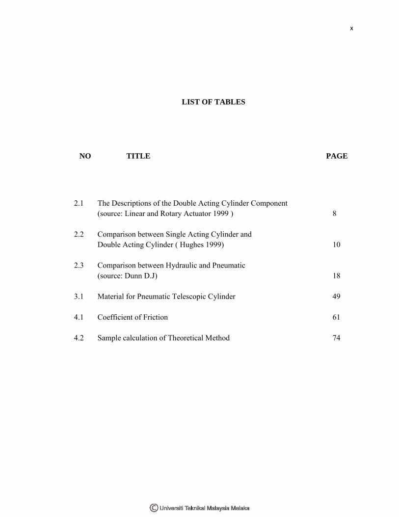
2.1 The Descriptions of the Double Acting Cylinder Component (source: Linear and Rotary Actuator 1999 ) 8 2.2 Comparison between Single Acting Cylinder and Double Acting Cylinder ( Hughes 1999) 10 2.3 Comparison between Hydraulic and Pneumatic (source: Dunn D.J) 18 3.1 Material for Pneumatic Telescopic Cylinder 49 4.1 Coefficient of Friction 61 4.2 Sample calculation of Theoretical Method 74
xi
LIST OF FIGURE
NO TITLE PAGE
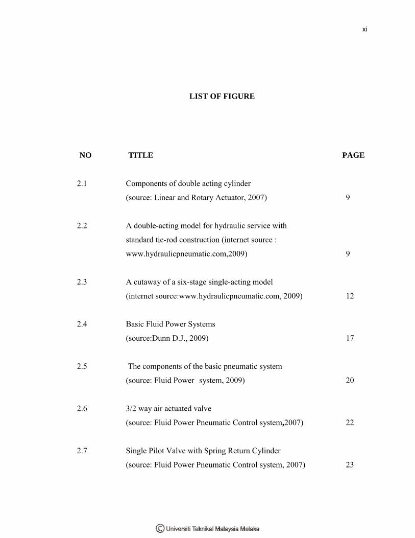
2.1 Components of double acting cylinder
(source: Linear and Rotary Actuator, 2007) 9
2.2 A double-acting model for hydraulic service with
standard tie-rod construction (internet source :
www.hydraulicpneumatic.com,2009) 9
2.3 A cutaway of a six-stage single-acting model
(internet source:www.hydraulicpneumatic.com, 2009) 12
2.4 Basic Fluid Power Systems
(source:Dunn D.J., 2009) 17
2.5 The components of the basic pneumatic system
(source: Fluid Power system, 2009) 20
2.6 3/2 way air actuated valve
(source: Fluid Power Pneumatic Control system,2007) 22
2.7 Single Pilot Valve with Spring Return Cylinder
(source: Fluid Power Pneumatic Control system, 2007) 23
xii
2.8 5/2 Way Valve for Double Pilot Valve
(source: Fluid Power Pneumatic Control System, 2007) 23
2.9 Check Valve symbol
(source: Fluid Power Pneumatic Control system, 2007) 24
2.10 Adjustable Flow Control Valve symbol
(internet source: Fluid Power
Pneumatic Control System,2007) 24
2.11 One-way Flow control valve (internet source:
Fluid Power Pneumatic Control System,2007) 24
2.12 Air Service Unit (internet source:
Fluid Power Pneumatic Control System,2007) 25
2.13 Compressed Air Regulator (internet source:
Fluid Power Pneumatic Control System,2007) 26
2.14 Compressed Air Lubricator (internet source:
Fluid Power Pneumatic Control System,2007) 27
2.15 Single Stage (source: Compressor and Air Preparation, 2007) 28
2.16 2 stage (source: Compressor and Air Preparation, 2007) 29
2.17 Diaphragm Compressor (source: Compressor and
Air Preparation, 2007) 30
xiii
2.18 Sliding Vane (source: Compressor and
Air Preparation, 2007) 31
2.19 Screw Compressor Principle
(source: Compressor and Air Preparation, 2007) 32
2.20 Sizing Cylinder during Extension
(Linear and Rotary Actuator, 2007) 32
2.21 Sizing Cylinder during Retraction
(Linear and Rotary Actuator) 33
3.1 The Methodology Flow 39
3.2 Pneumatic telescopic Cylinder (source: Aida, R., 2009) 41
3.3 Assembly design of Telescopic Cylinder 42
3.4 Telescopic Cylinder Housing 42
3.5 Telescopic Cylinder Shaft 1 43
3.6 Telescopic Cylinder Shaft 2 43
3.7 Telescopic Cylinder Guide bushing 1 44
3.8 Telescopic Cylinder Guide bushing 1 44
3.8 Telescopic Cylinder End Cup 45

xiv
3.9 Lathe machine
(internet source:www.olympiclathe.com, 2007) 46
3.10 Milling machine
(internet source :www.milling-machine.info,2008) 48
3.11 Cylinder control system 50
3.12 Programmable Logic Controller 51
3.13 Pneumatic Telescopic Cylinder 51
3.14 Compressor 52
3.15 Load 52
3.16 Stopwatch 52
3.17 First Stage Cylinder Extension 53
3.18 System component of PLC 55
4.1 Force Analysis for Cylinder 1 57
4.2 Force Analysis for Cylinder 2 59
4.3 Theoretical Graph Pressure against Velocity
for load = 0.1 kg 63
xv
4.4 Theoretical Graph Pressure against Velocity
for load = 0.2 kg 63
4.5 Theoretical Graph Pressure against Velocity
for load = 0.3 kg 64
4.6 Theoretical Graph Pressure against Velocity
for load = 0.4 kg 64
4.7 Theoretical Graph Pressure against Velocity
for load = 0.5 kg 65
4.8 Theoretical Graph Pressure against Velocity
for load = 0.6 kg 65
4.9 Theoretical Graph Pressure against Velocity
for load = 0.7 kg 66
4.10 Theoretical Graph Pressure against Velocity
for load = 0.8 kg 66
4.11 Theoretical Graph Pressure against Velocity
for load = 0.9 kg 67
4.12 Theoretical Graph Pressure against Velocity
for load = 1.0 kg 67
4.13 Theoretical Graph Pressure against Velocity
for load = 1.1 kg 68
xvi
4.14 Theoretical Graph Pressure against Velocity
for load = 1.2kg 68
4.15 Theoretical Graph Pressure against Velocity
for load = 1.3 kg 69
4.16 Theoretical Graph Pressure against Velocity
for load = 1.4 kg 69
4.17 Theoretical Graph Pressure against Velocity
for load = 15 kg 70
4.18 Theoretical Graph Pressure against Velocity
for load = 1.6 kg 70
4.19 Theoretical Graph Pressure against Velocity
for load = 1.7 kg 71
4.20 Theoretical Graph Pressure against Velocity
for load = 1.8 kg 71
4.21 Theoretical Graph Pressure against Velocity
for load = 1.9 kg 72
4.22 Theoretical Graph Pressure against Velocity
for load = 2.0 kg 72
4.23 Experimental Graph Pressure against Velocity
for load = 0.1 kg 77
xvii
4.24 Experimental Graph Pressure against Velocity
for load = 0.2 kg 77
4.25 Experimental Graph Pressure against Velocity
for load = 0.3 kg 78
4.26 Experimental Graph Pressure against Velocity
for load = 0.4 kg 78
4.27 Experimental Graph Pressure against Velocity
for load = 0.5 kg 79
4.28 Experimental Graph Pressure against Velocity
for load = 0.6 kg 79
4.29 Experimental Graph Pressure against Velocity
for load = 0.7 kg 80
4.30 Experimental Graph Pressure against Velocity
for load = 0.8 kg 80
4.31 Experimental Graph Pressure against Velocity
for load = 0.9 kg 81
4.32 Experimental Graph Pressure against Velocity
for load = 1.0 kg 81
4.33 Experimental Graph Pressure against Velocity
for load = 1.1 kg 82
xviii
4.34 Experimental Graph Pressure against Velocity
for load = 1.2kg 82
4.35 Experimental Graph Pressure against Velocity
for load = 1.3 kg 83
4.36 Experimental Graph Pressure against Velocity
for load = 1.4 kg 83
4.37 Experimental Graph Pressure against Velocity
for load = 15 kg 102
4.38 Experimental Graph Pressure against Velocity
for load = 1.6 kg 84
4.39 Experimental Graph Pressure against Velocity
for load = 1.7 kg 85
4.40 Experimental Graph Pressure against Velocity
for load = 1.8 kg 85
4.41 Experimental Graph Pressure against Velocity
for load = 1.9 kg 86
4.42 Experimental Graph Pressure against Velocity
for load = 2.0 kg 86
5.1 Graph Pressure against Velocity for Cylinder 1
for Load 0.1 kg until 2.0 kg (Theoretical) 93
xix
5.2 Graph Pressure against Velocity for Cylinder 2
for Load 0.1 kg until 2.0 kg (Theoretical) 93
5.3 Graph Pressure against Velocity for Cylinder 1
for Load 0.1 kg until 2.0 kg (Experimental) 96
5.4 Graph Pressure against Velocity for Cylinder 2
for Load 0.1 kg until 2.0 kg (Experimental) 96
5.5 Graphical Method for Cylinder 1 97
5.6 Graphical Method for Cylinder 2 98
xx
LIST OF SYMBOLS
Q = flow rate (GPM)
A = area (m/s-2)
F = force (N)
P = pressure (Pa)
Q = compressor inlet air flow rate. (Standard m3/min)
Pin = inlet absolute pressure of air. (kPa)
Pout = outlet absolute pressure of air. (kPa)
x = Piston’s position (m)
Ff = Friction force
= Mass (kg)
a =Acceleration, (m/s-2)
v0 =Initial velocity, (m/s)
v =Velocity, (m/s)
t = time, (s)
xxi
LIST OF APPENDICES
NO TITLE PAGE
A Open Control Step and Stop in PLC for Cylinder 110
B Pneumatic Telescopic Cylinder Assembly Drawing 112
C Housing for Pneumatic Telescopic Drawing 113
D Shaft 1 for Pneumatic Telescopic Drawing 114
E Guiding Bush 1 for Pneumatic Telescopic Cylinder
Drawing 115
F Guiding Bush 2 for Pneumatic Telescopic Cylinder
Drawing 116
G Shaft 2 for Pneumatic Telescopic Cylinder 117
H End Cap for Pneumatic Telescopic Cylinder Drawing 118
I Theoretical Result for Cylinder 1 119
J Theoretical Result for Cylinder 2 123
xxii
K Experimental Result 127
L Percentage Error for Cylinder 1 and Cylinder 2 131
M PLC Schematic Diagram for Cylinder 135
1
CHAPTER I
INTRODUCTION
Projek Sarjana Muda (PSM) is a scientific and education studies about the
course taken in the faculty. This project must be prepared by final year students as a
requirement for students to become a bachelor of mechanical engineering in
Universiti Teknikal Malaysia Melaka (UTeM).
1.1 Background Of Project
Pneumatic is a fluid power that is widely used in the industrial application.
Pneumatic through the compressed air or other gas is used to transmit power to
actuating mechanisms. The pneumatic system is low cost, lightweight, unpolluted,
highly safe, easy to fix or repair and soft output. Semiconductor business and auto-
producing system are the examples of industry that use the pneumatic system
technique frequently.
In industry actuators, pneumatic cylinder is the most common type which
provides the enumerated qualities at low cost as well as suitable for clean
environments. It is safer and easier to work with if compared to the conventional
electric and hydraulic actuators. It also becomes an alternative in certain types of
applications. A pneumatic cylinder has a lower specific weight and a higher power
rate than an equivalent electromechanical actuator. In some cases, a pneumatic
system has a significant weight of advantage.
2
In either hydraulic or pneumatic, telescopic cylinder is designed and applied
to minimize the length of the stroke when in retracted position. For localized
applications of considerable forces in areas that lack sufficient space, it can be found
as telescoping fluid actuator. Other applications are for agricultural tools or for
vehicle used in construction and maintenance work on overhead system. The
telescopic cylinders were mounted on the platform and can be lifted enough to reach
the uppermost parts of the structure. In summary, telescopic cylinders have their own
unique performance characteristics and it is the responsibility of the user to take them
into account when selecting one for their specific application.
1.2 Objective
The objective of this project is to study the pneumatic telescopic cylinder arm
operation for variable load applications.
1.3 Scope
i. Do the literature review of the previous study of pneumatic telescopic
cylinder and its application.
ii. Study the theories that are applied in the pneumatic telescopic cylinder
and the variable load lifting system.
iii. Run an experiment of the pneumatic telescopic cylinder for variable load
lifting application.
3
1.4 Problem Statement
The application of fluid power for mechanical equipments is widely used
today. Pneumatic and hydraulic are fluid power that are commonly used in industry.
However, the hydraulic power is high cost. This is because the installation of
hydraulic equipment generally calls for greater skills and hence costs more. Besides
that, the maintenance costs for hydraulic are expensive and the application of
hydraulic can causes pollution.
In certain application, the common linear actuators need a large space to
operate. This is because linear actuators do not have enough space to operate where
force is considered in a limited space.
The velocity of the cylinder for each stage is different according to the load
applied. Therefore, a study of the pneumatic telescopic arm operation is necessary in
order to determine the movement of each stage of the cylinder when variable of load
is applied. Besides that, the study is also important to determine the pressure effect
and the load effect on the cylinder movement. The purpose is to make sure that for
certain required velocity, the pressure is sufficient to carry the load.