Embed Size (px)
Citation preview
DESCRIPTION
DECORATOR COMFORT CONTROL (DCC)
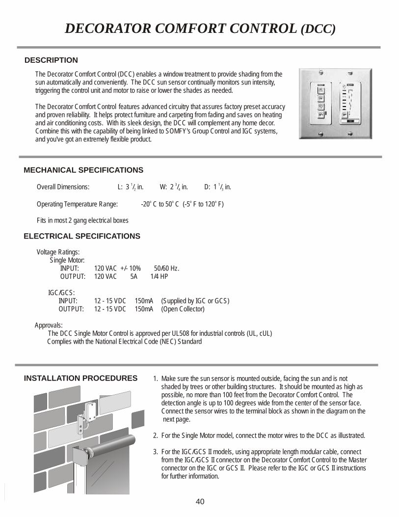
The Decorator Comfort Control (DCC) enables a window treatment to provide shading from the sun automatically and conveniently. The DCC sun sensor continually monitors sun intensity, triggering the control unit and motor to raise or lower the shades as needed.
The Decorator Comfort Control features advanced circuitry that assures factory preset accuracy and proven reliability. It helps protect furniture and carpeting from fading and saves on heating and air conditioning costs. With its sleek design, the DCC will complement any home decor. Combine this with the capability of being linked to SOMFY's Group Control and IGC systems, and you've got an extremely flexible product.
INSTALLATION PROCEDURES 1. Make sure the sun sensor is mounted outside, facing the sun and is not shaded by trees or other building structures. It should be mounted as high as possible, no more than 100 feet from the Decorator Comfort Control. The detection angle is up to 100 degrees wide from the center of the sensor face. Connect the sensor wires to the terminal block as shown in the diagram on the next page.
2. For the Single Motor model, connect the motor wires to the DCC as illustrated.
3. For the IGC/GCS II models, using appropriate length modular cable, connect from the IGC/GCS II connector on the Decorator Comfort Control to the Master connector on the IGC or GCS II. Please refer to the IGC or GCS II instructions for further information.
MECHANICAL SPECIFICATIONS
1 3 1 Overall Dimensions: L: 3 / in. W: 2 / in. D: 1 / in.2 4 3
o o o o
Operating Temperature Range: -20 C to 50 C (-5 F to 120 F) Fits in most 2 gang electrical boxes
ELECTRICAL SPECIFICATIONS
Voltage Ratings: Single Motor:
INPUT: 120 VAC +/- 10% 50/60 Hz. OUTPUT: 120 VAC 5A 1/4 HP IGC/GCS: INPUT: 12 - 15 VDC 150mA (Supplied by IGC or GCS) OUTPUT: 12 - 15 VDC 150mA (Open Collector) Approvals: The DCC Single Motor Control is approved per UL508 for industrial controls (UL, cUL)
Complies with the National Electrical Code (NEC) Standard
40
OPERATING PROCEDURES
depending on its previous status. Manual mode is designated by1. Pressing the UP button will move the window covering up. the LED being off. If the DCC is in manual mode, the sun level hasPressing the DOWN button will lower it when pressed. If a motor does no influence on motor control. not move in the correct direction, turn off the circuit breaker(s) and
reverse the red and black wires at the corresponding motor(s). 5. With the Summer/Winter switch in the SUMMER position (to the
left), the Decorator Comfort Control sun functions will operate as2. Pressing the STOP button will stop the motor in its present outlined above. When the switch is in the WINTER position (to the position. right) the Decorator Comfort Control sun functions will operate in the opposite directions. Manual operation will cancel automatic3. When the monitored sun intensity is greater than the DCC setting, function for one full cycle. To reset, press the auto button OFF and the DOWN direction will activate after 3.5 minutes. The sun LED ON. will remain on for as long as this condition exists. If the sun
intensity is less than the DCC setting, the UP direction will activate after 15 minutes (if the auto LED is illuminated). The sun LED will blink during this time period.
4. When the AUTO button is pressed, the AUTO LED will turn on or off
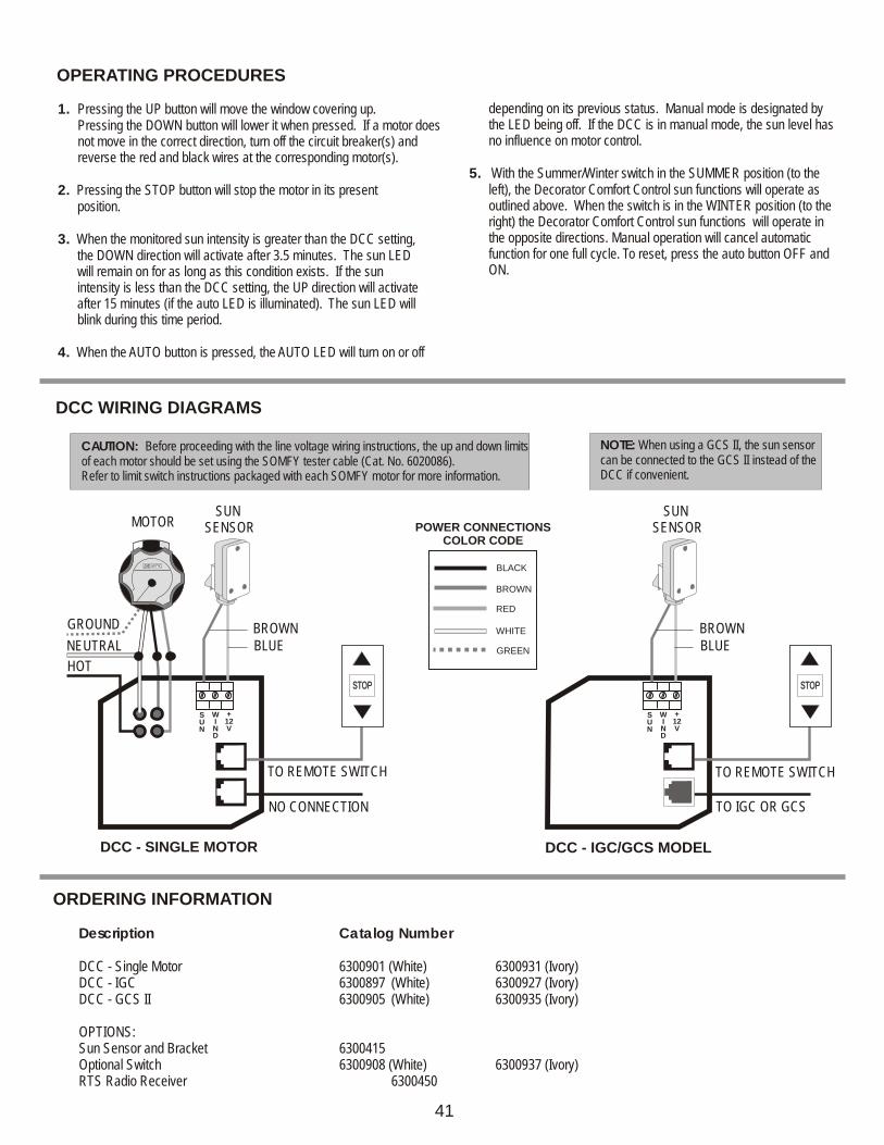
DCC WIRING DIAGRAMS
ORDERING INFORMATION
TO IGC OR GCS
DCC - IGC/GCS MODEL
SUN
SUN
WIND
WIND
+12V
+12V
SUN SENSOR
SUN SENSORMOTOR
NEUTRAL
HOT
GROUND
TO REMOTE SWITCH
BROWN BROWNBLUE BLUE
TO REMOTE SWITCH
NO CONNECTION
DCC - SINGLE MOTOR
RR
Description Catalog Number
DCC - Single Motor 6300901 (White) 6300931 (Ivory)DCC - IGC 6300897 (White) 6300927 (Ivory)DCC - GCS II 6300905 (White) 6300935 (Ivory)
OPTIONS:Sun Sensor and Bracket 6300415Optional Switch 6300908 (White) 6300937 (Ivory)RTS Radio Receiver 6300450
STOPSTOP STOPSTOP
CAUTION: Before proceeding with the line voltage wiring instructions, the up and down limits of each motor should be set using the SOMFY tester cable (Cat. No. 6020086).Refer to limit switch instructions packaged with each SOMFY motor for more information.
NOTE: When using a GCS II, the sun sensor can be connected to the GCS II instead of the DCC if convenient.
41
BROWN
BLACK
RED
WHITE
GREEN
POWER CONNECTIONSCOLOR CODE
MECHANICAL SPECIFICATIONS
1 1 Overall Dimensions: L: 6 in. W: 4 / in. D: 2 / in.4 4
Wind Speed: 12 to 31 mph
EOLISWind Control
DESCRIPTION
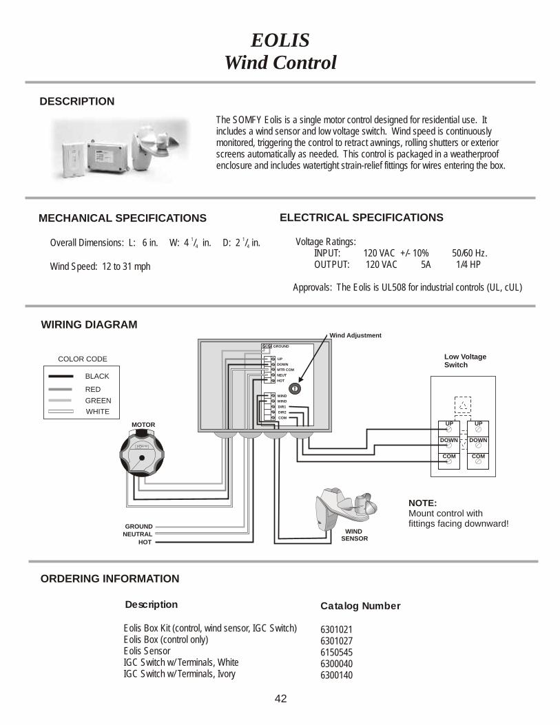
The SOMFY Eolis is a single motor control designed for residential use. It includes a wind sensor and low voltage switch. Wind speed is continuously monitored, triggering the control to retract awnings, rolling shutters or exterior screens automatically as needed. This control is packaged in a weatherproof enclosure and includes watertight strain-relief fittings for wires entering the box.
ELECTRICAL SPECIFICATIONS
Voltage Ratings: INPUT: 120 VAC +/- 10% 50/60 Hz. OUTPUT: 120 VAC 5A 1/4 HP
Approvals: The Eolis is UL508 for industrial controls (UL, cUL)
Description
Eolis Box Kit (control, wind sensor, IGC Switch) Eolis Box (control only) Eolis Sensor IGC Switch w/ Terminals, White IGC Switch w/ Terminals, Ivory
ORDERING INFORMATION
Catalog Number
63010216301027615054563000406300140
UP
DOWN
COM
UP
DOWN
COM
WIRING DIAGRAM
MOTOR
RR
WIND SENSOR
HOT
NEUTRALGROUND
BLACK
RED
GREEN
WHITE
COLOR CODE
Wind Adjustment
NOTE:Mount control with fittings facing downward!x
UP
GROUND
WIND
WIND
DIR1
DIR2
COM
DOWN
MTR COM
NEUT
HOT
Low Voltage Switch
42
INSTALLATION PROCEDURES
MECHANICAL SPECIFICATIONS
1 1 Overall Dimensions: L: 6 in. W: 4 / in. D: 2 / in.4 4
Wind Speed: 12 to 31 mph
Frequency Range (optimal conditions): 65 ft.
EOLISRECEIVER
WINDSENSOR
EOLIS RTS RECEIVERWind-Remote Control
DESCRIPTION
x
x
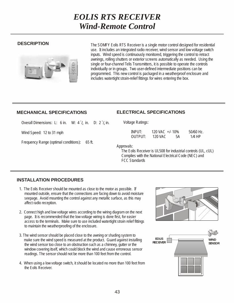
The SOMFY Eolis RTS Receiver is a single motor control designed for residential use. It includes an integrated radio receiver, wind sensor and low voltage switch inputs. Wind speed is continuously monitored, triggering the control to retract awnings, rolling shutters or exterior screens automatically as needed. Using the single or four-channel Telis Transmitters, it is possible to operate the controls individually or in groups. Two user-defined intermediate positions can be programmed. This new control is packaged in a weatherproof enclosure and includes watertight strain-relief fittings for wires entering the box.
1. The Eolis Receiver should be mounted as close to the motor as possible. If mounted outside, ensure that the connections are facing down to avoid moisture seepage. Avoid mounting the control against any metallic surface, as this may affect radio reception.
2. Connect high and low voltage wires according to the wiring diagram on the next page.
Make sure to use included watertight strain relief fittings to maintain the weatherproofing of the enclosure.
3. The wind sensor should be placed close to the awning or shading system to make sure the wind speed is measured at the product. Guard against installing
the wind sensor too close to an obstruction such as a chimney, gutter or the window covering itself, which could block the wind and cause erroneous sensor readings. The sensor should not be more than 100 feet from the control.
4. When using a low voltage switch, it should be located no more than 100 feet from the Eolis Receiver.
It is recommended that the low voltage wiring is done first, for easier access to the terminals.
43
ELECTRICAL SPECIFICATIONS
Voltage Ratings:
INPUT: 120 VAC +/- 10% 50/60 Hz. OUTPUT: 120 VAC 5A 1/4 HP
Approvals: The Eolis Receiver is UL508 for industrial controls (UL, cUL) Complies with the National Electrical Code (NEC) and FCC Standards
Description
Eolis Receiver Kit (control & wind sensor) Eolis Receiver (control only) Eolis Sensor SPST Momentary Switch
WIRING DIAGRAM
MOTOR
RR
WIND SENSORHOT
NEUTRALGROUND
BLACK
RED
GREEN
WHITE
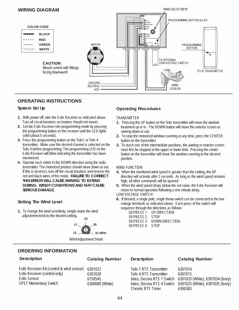
COLOR CODE
WIND ADJUSTMENT
PROGRAMMING BUTTON & LED
TO OPTIONALLOW VOLTAGE SWITCHCAUTION:
Mount control with fittings facing downward!
x
PROGRAMMING BUTTON
TELIS TRANSMITTER
UP
WIND
WIND
DOWN
MTR COM
NEUT
HOT
OPERATING INSTRUCTIONS
44
Description
Telis 1 RTS Transmitter Telis 4 RTS Transmitter Inteo, Decora RTS 1 Switch Inteo, Decora RTS 4 Switch Chronis RTS Timer
System Set Up
1. With power off, wire the Eolis Receiver as indicated above. Turn all circuit breakers on (motors should not move).
2. Set the Eolis Receiver into programming mode by pressing the programming button on the receiver until the LED lights solid (about 5 seconds).
3. Press the programming button on the Telis1 or Telis 4 transmitter. Make sure the desired channel is selected on the Telis 4 before programming. The programming LED on the Eolis Receiver will blink indicating the transmitter has been memorized.
4. Operate each motor in the DOWN direction using the radio transmitter. The motorized product should move down or out. If this is incorrect, turn off the circuit breakers and reverse the red and black wires of the motor. FAILURE TO CORRECT THIS ERROR WILL CAUSE AWNING TO EXTEND DURING WINDY CONDITIONS AND MAY CAUSE SERIOUS DAMAGE.
Setting The Wind Level
1. To change the wind sensitivity, simply rotate the wind adjustment knob to the desired setting.
ORDERING INFORMATION
Catalog Number
6301022630102861505456300080 (White)
Catalog Number
630101463010156301033 (White), 6301034 (Ivory)6301025 (White), 6301035 (Ivory) 6300383
31 MPH12
17 26
22
Wind Adjustment Detail
Operating Procedures
TRANSMITTER 1. Pressing the UP button on the Telis transmitter will move the window treatment up or in. The DOWN button will move the exterior screen or
awning down or out.2. To stop the motorized window covering at any time, press the CENTER
button on the transmitter.3. To reach one of the intermediate positions, the awning or exterior screen
must first be stopped at the upper or lower limit. Pressing the center button on the transmitter will move the window covering to the desired position.
WIND FUNCTION4. When the monitored wind speed is greater than the setting, the UP direction will activate after 2 seconds. As long as the wind speed remains
high, all other commands will be ignored.5. When the wind speed drops below the set value, the Eolis Receiver will
return to normal operation following a one minute delay.LOW VOLTAGE SWITCH6. If desired, a single pole, single throw switch can be connected to the low
voltage terminals as indicated above. Each press of the switch will sequence through the directions as follows: DEPRESS 1 UP DIRECTION DEPRESS 2 STOP DEPRESS 3 DOWN DIRECTION DEPRESS 4 STOP
INSTALLATION PROCEDURES
MECHANICAL SPECIFICATIONS
1 1 Overall Dimensions: L: 6 in. W: 4 / in. D: 2 / in.4 4
Frequency Range (Optimal Conditions): 65 ft.
Wind Speed: 12 to 31 mph
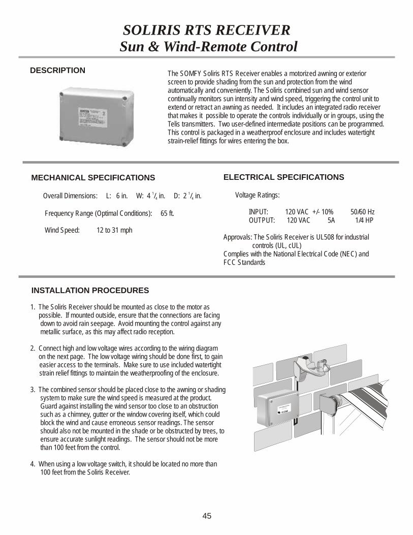
SOLIRIS RTS RECEIVER Sun & Wind-Remote Control
DESCRIPTION The SOMFY Soliris RTS Receiver enables a motorized awning or exterior screen to provide shading from the sun and protection from the wind automatically and conveniently. The Soliris combined sun and wind sensor continually monitors sun intensity and wind speed, triggering the control unit to extend or retract an awning as needed. It includes an integrated radio receiver that makes it possible to operate the controls individually or in groups, using the Telis transmitters. Two user-defined intermediate positions can be programmed. This control is packaged in a weatherproof enclosure and includes watertight strain-relief fittings for wires entering the box.
1. The Soliris Receiver should be mounted as close to the motor as possible. If mounted outside, ensure that the connections are facing
down to avoid rain seepage. Avoid mounting the control against any metallic surface, as this may affect radio reception.
2. Connect high and low voltage wires according to the wiring diagram on the next page. T
Make sure to use included watertight strain relief fittings to maintain the weatherproofing of the enclosure.
3. The combined sensor should be placed close to the awning or shading system to make sure the wind speed is measured at the product. Guard against installing the wind sensor too close to an obstruction such as a chimney, gutter or the window covering itself, which could block the wind and cause erroneous sensor readings. The sensor should also not be mounted in the shade or be obstructed by trees, to ensure accurate sunlight readings. The sensor should not be more than 100 feet from the control.
4. When using a low voltage switch, it should be located no more than 100 feet from the Soliris Receiver.
he low voltage wiring should be done first, to gain easier access to the terminals.
x
45
ELECTRICAL SPECIFICATIONS
Voltage Ratings:
INPUT: 120 VAC +/- 10% 50/60 Hz OUTPUT: 120 VAC 5A 1/4 HP
Approvals: The Soliris Receiver is UL508 for industrial controls (UL, cUL)Complies with the National Electrical Code (NEC) and FCC Standards
ORDERING INFORMATION
Description
Soliris Receiver Kit (control & combined sensor) Soliris Receiver (control only) Soliris Sensor Telis Soliris Transmitter SPST Momentary Switch
OPERATING INSTRUCTIONS
WIRING DIAGRAM
MOTOR
RR
COMBINED SENSOR
NEUTRALGROUND
BLACK
RED
GREEN
WHITE
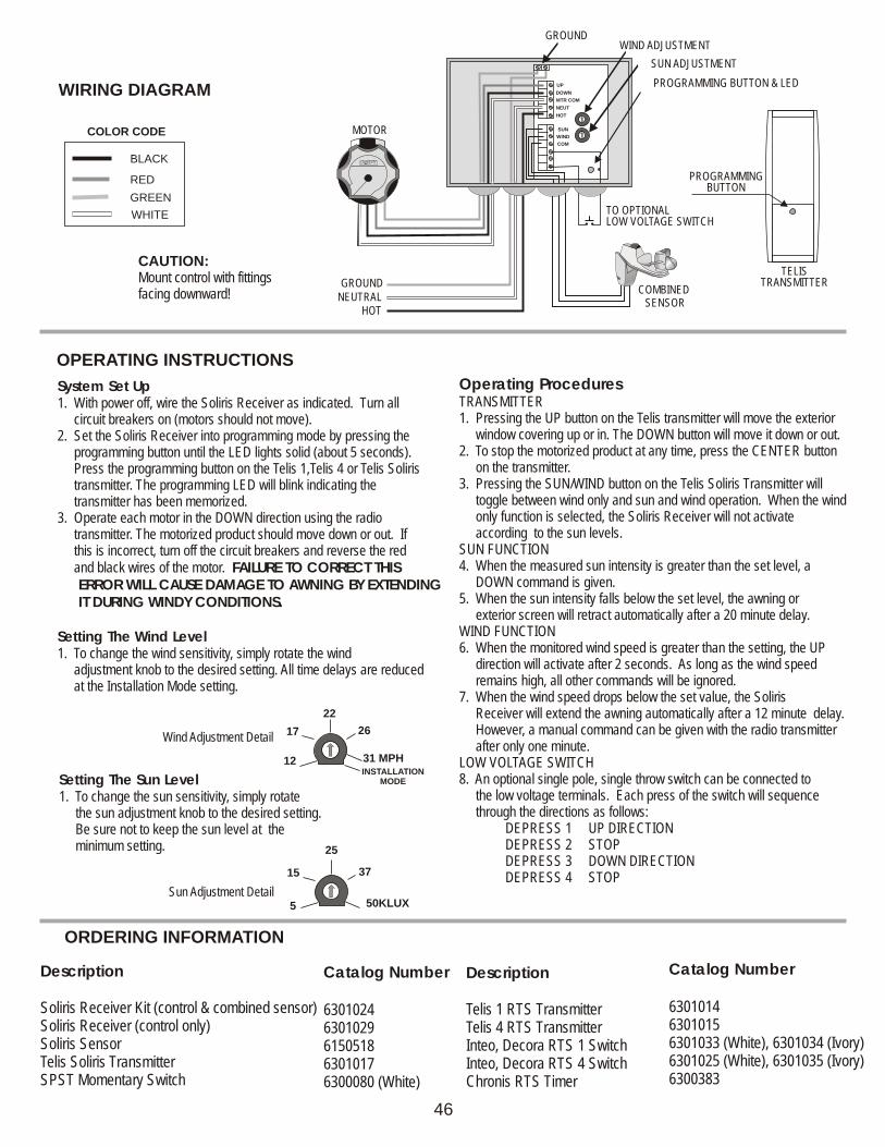
COLOR CODE
WIND ADJUSTMENTGROUND
SUN ADJUSTMENT
PROGRAMMING BUTTON & LED
TO OPTIONALLOW VOLTAGE SWITCH
CAUTION:Mount control with fittings facing downward!
x
PROGRAMMING BUTTON
TELIS TRANSMITTER
UP
WIND
SUN
COM
DOWN
MTR COM
NEUT
HOT
HOT
Operating Procedures
1. Pressing the UP button on the Telis transmitter will move the exterior window covering up or in. The DOWN button will move it down or out.2. To stop the motorized product at any time, press the CENTER button on the transmitter.3. Pressing the SUN/WIND button on the Telis Soliris Transmitter will toggle between wind only and sun and wind operation. When the wind only function is selected, the Soliris Receiver will not activate according to the sun levels.
6. When the monitored wind speed is greater than the setting, the UP direction will activate after 2 seconds. As long as the wind speed remains high, all other commands will be ignored.7. When the wind speed drops below the set value, the Soliris Receiver will extend the awning automatically after a 12 minute delay. However, a manual command can be given with the radio transmitter after only one minute.
TRANSMITTER
SUN FUNCTION4. When the measured sun intensity is greater than the set level, a DOWN command is given. 5. When the sun intensity falls below the set level, the awning or exterior screen will retract automatically after a 20 minute delay. WIND FUNCTION
LOW VOLTAGE SWITCH8. An optional single pole, single throw switch can be connected to the low voltage terminals. Each press of the switch will sequence through the directions as follows: DEPRESS 1 UP DIRECTION DEPRESS 2 STOP DEPRESS 3 DOWN DIRECTION DEPRESS 4 STOP
50KLUX5
15 37
25
31 MPH12
17 26
22
INSTALLATIONMODE
46
Description
Telis 1 RTS Transmitter Telis 4 RTS Transmitter Inteo, Decora RTS 1 Switch Inteo, Decora RTS 4 SwitchChronis RTS Timer
System Set Up1. With power off, wire the Soliris Receiver as indicated. Turn all circuit breakers on (motors should not move).2. Set the Soliris Receiver into programming mode by pressing the programming button until the LED lights solid (about 5 seconds). Press the programming button on the Telis 1,Telis 4 or Telis Soliris transmitter. The programming LED will blink indicating the transmitter has been memorized.3. Operate each motor in the DOWN direction using the radio transmitter. The motorized product should move down or out. If this is incorrect, turn off the circuit breakers and reverse the red and black wires of the motor. FAILURE TO CORRECT THIS ERROR WILL CAUSE DAMAGE TO AWNING BY EXTENDING IT DURING WINDY CONDITIONS.
Setting The Wind Level1. To change the wind sensitivity, simply rotate the wind adjustment knob to the desired setting. All time delays are reduced at the Installation Mode setting.
Wind Adjustment Detail
Setting The Sun Level1. To change the sun sensitivity, simply rotate the sun adjustment knob to the desired setting. Be sure not to keep the sun level at the minimum setting.
Sun Adjustment Detail
Catalog Number
63010246301029615051863010176300080 (White)
Catalog Number
630101463010156301033 (White), 6301034 (Ivory)6301025 (White), 6301035 (Ivory) 6300383
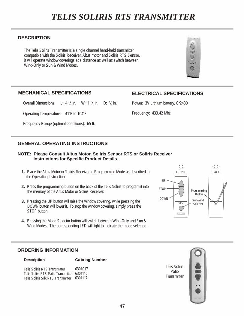
TELIS SOLIRIS RTS TRANSMITTER
DESCRIPTION
The Telis Soliris Transmitter is a single channel hand-held transmitter compatible with the Soliris Receiver, Altus motor and Soliris RTS Sensor.It will operate window coverings at a distance as well as switch betweenWind-Only or Sun & Wind Modes.
FRONT
Sun/WindSelector
ProgrammingButton
BACK
MECHANICAL SPECIFICATIONS
3 3 3 Overall Dimensions: L: 4 / in. W: 1 / in. D: / in. 4 4 4
o o Operating Temperature: 41 F to 104 F
Frequency Range (optimal conditions): 65 ft.
ELECTRICAL SPECIFICATIONS
Power: 3V Lithium battery, Cr2430
Frequency: 433.42 Mhz
GENERAL OPERATING INSTRUCTIONS
NOTE: Please Consult Altus Motor, Soliris Sensor RTS or Soliris Receiver Instructions for Specific Product Details.
1. Place the Altus Motor or Soliris Receiver in Programming Mode as described in the Operating Instructions.
2. Press the programming button on the back of the Telis Soliris to program it into the memory of the Altus Motor or Soliris Receiver.
3. Pressing the UP button will raise the window covering, while pressing the DOWN button will lower it. To stop the window , simply press the STOP button.
4. Pressing the Mode Selector button will switch between Wind-Only and Sun & Wind Modes. The corresponding LED will light to indicate the mode selected.
covering
UP
STOP
DOWN
47
Description
Telis Soliris RTS TransmitterTelis Solirs RTS Patio TransmitterTelis Soliris Silk RTS Transmitter
Catalog Number
630101763011166301117
ORDERING INFORMATION
Telis SolirisPatio
Transmitter
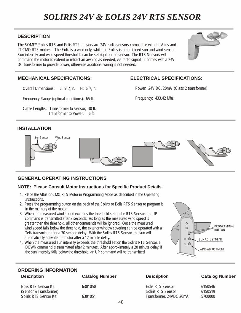
SOLIRIS 24V & EOLIS 24V RTS SENSOR
DESCRIPTION
MECHANICAL SPECIFICATIONS:
1 1 Overall Dimensions: L: 9 / in. H: 6 / in. 3 3
Frequency Range (optimal conditions): 65 ft.
Cable Lengths: Transformer to Sensor; 30 ft. Transformer to Power; 6 ft.
ELECTRICAL SPECIFICATIONS:
Power: 24V DC, 20mA (Class 2 transformer)
Frequency: 433.42 Mhz
GENERAL OPERATING INSTRUCTIONS
NOTE: Please Consult Motor Instructions for Specific Product Details.
INSTALLATION
ORDERING INFORMATION
1. Place the Altus or CMO RTS Motor in Programming Mode as described in the Operating Instructions.
2. Press the programming button on the back of the Soliris or Eolis RTS Sensor to program it in the memory of the motor.
3. When the measured wind speed exceeds the threshold set on the RTS Sensor, an UP command is transmitted after 2 seconds. As long as the measured wind speed is
greater then the threshold, all other commands will be ignored. Once the measured wind speed falls below the threshold, the exterior window covering can be operated with a
Telis transmitter after a 30 second delay. With the Soliris RTS Sensor, the sun will automatically activate the motor after a 12 minute delay.4. When the measured sun intensity exceeds the threshold set on the Soliris RTS Sensor, a
DOWN command is transmitted after 2 minutes. A f the sun intensity falls below the threshold, an UP command will be transmitted.
fter approximately a 20 minute delay, i
The SOMFY Soliris RTS and Eolis RTS sensors are 24V radio sensors compatible with the Altus and LT CMO RTS motors. The Eolis is a wind only, while the Soliris is a combined sun and wind sensor. Sun intensity and wind speed thresholds can be set right on the sensor. The RTS Sensors will command the motor to extend or retract an awning as needed, via radio signal. It comes with a 24V DC transformer to provide power, otherwise additional wiring is not needed.
x
x
x
x
Sun Sensor Wind Sensor
- +
- +
PROGRAMMING BUTTON
SUN ADJUSTMENT
WIND ADJUSTMENT
Description
Eolis RTS SensorSoliris RTS SensorTransformer, 24VDC 20mA
Description
Eolis RTS Sensor Kit(Sensor & Transformer)Soliris RTS Sensor Kit
Catalog Number
615054661505195700000
Catalog Number
6301050
6301051
48
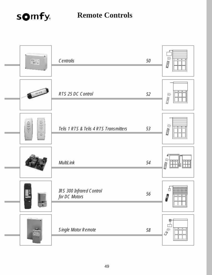
Telis 1 RTS & Telis 4 RTS Transmitters
Centralis
56
53
50
IRS 300 Infrared Controlfor DC Motors
Remote Controls
49
RTS 25 DC Control 52
stop stop
58Single Motor Remote
MultiLink 54
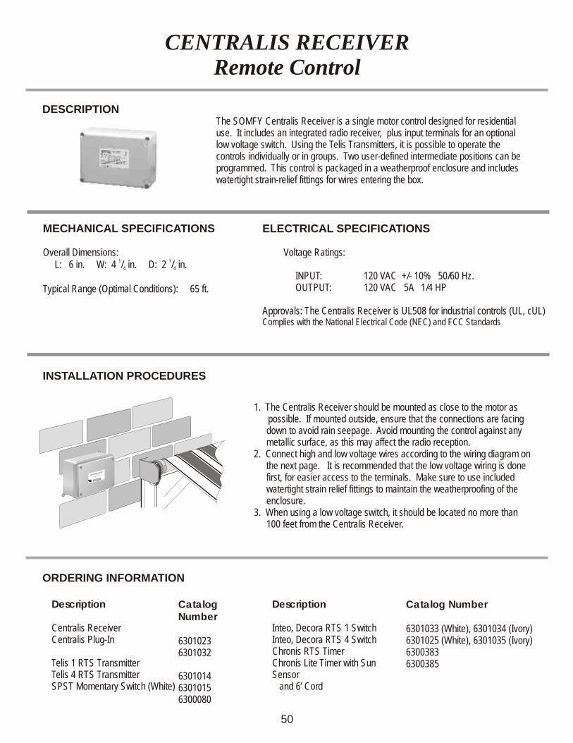
MECHANICAL SPECIFICATIONS
Overall Dimensions: 1 1
L: 6 in. W: 4 / in. D: 2 / in.4 4
Typical Range (Optimal Conditions): 65 ft.
CENTRALIS RECEIVERRemote Control
DESCRIPTIONThe SOMFY Centralis Receiver is a single motor control designed for residential use. It includes an integrated radio receiver, plus input terminals for an optional low voltage switch. Using the Telis Transmitters, it is possible to operate the controls individually or in groups. Two user-defined intermediate positions can be programmed. This control is packaged in a weatherproof enclosure and includes watertight strain-relief fittings for wires entering the box.
INSTALLATION PROCEDURES
1. The Centralis Receiver should be mounted as close to the motor as possible. If mounted outside, ensure that the connections are facing
down to avoid rain seepage. Avoid mounting the control against any metallic surface, as this may affect the radio reception.
2. Connect high and low voltage wires according to the wiring diagram on the next page.
Make sure to use included watertight strain relief fittings to maintain the weatherproofing of the enclosure.
3. When using a low voltage switch, it should be located no more than 100 feet from the Centralis Receiver.
It is recommended that the low voltage wiring is done first, for easier access to the terminals.
Description
Centralis ReceiverCentralis Plug-In
Telis 1 RTS TransmitterTelis 4 RTS TransmitterSPST Momentary Switch (White)
Description
Inteo, Decora RTS 1 SwitchInteo, Decora RTS 4 Switch Chronis RTS TimerChronis Lite Timer with Sun Sensor and 6’ Cord
ORDERING INFORMATION
50
ELECTRICAL SPECIFICATIONS
Voltage Ratings:
INPUT: 120 VAC +/- 10% 50/60 Hz. OUTPUT: 120 VAC 5A 1/4 HP
Approvals: The Centralis Receiver is UL508 for industrial controls (UL, cUL)Complies with the National Electrical Code (NEC) and FCC Standards
Catalog Number
63010236301032
630101463010156300080
Catalog Number
6301033 (White), 6301034 (Ivory)6301025 (White), 6301035 (Ivory)63003836300385
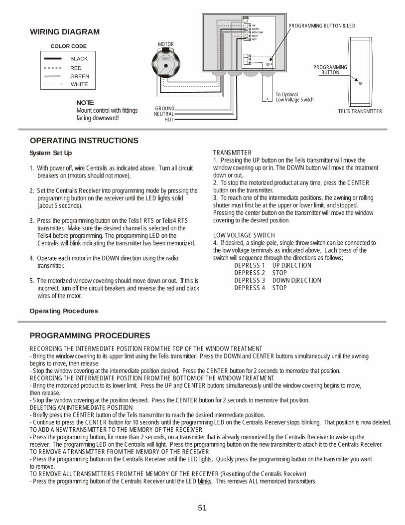
OPERATING INSTRUCTIONS
System Set Up1. Pressing the UP button on the Telis transmitter will move the window covering up or in. The DOWN button will move the treatment 1. With power off, wire Centralis as indicated above. Turn all circuit down or out.breakers on (motors should not move).2. To stop the motorized product at any time, press the CENTER button on the transmitter.2. Set the Centralis Receiver into programming mode by pressing the 3. To reach one of the intermediate positions, the awning or rolling programming button on the receiver until the LED lights solid shutter must first be at the upper or lower limit, and stopped. (about 5 seconds).Pressing the center button on the transmitter will move the window covering to the desired position.3. Press the programming button on the Telis1 RTS or Telis4 RTS
transmitter. Make sure the desired channel is selected on the Telis4 before programming. The programming LED on the Centralis will blink indicating the transmitter has been memorized.
4. Operate each motor in the DOWN direction using the radio transmitter.
5. The motorized window covering should move down or out. If this is incorrect, turn off the circuit breakers and reverse the red and black wires of the motor.
Operating Procedures
TRANSMITTER
LOW VOLTAGE SWITCH4. If desired, a single pole, single throw switch can be connected to the low voltage terminals as indicated above. Each press of the switch will sequence through the directions as follows; DEPRESS 1 UP DIRECTION DEPRESS 2 STOP DEPRESS 3 DOWN DIRECTION DEPRESS 4 STOP
WIRING DIAGRAM
MOTOR
RR
HOTNEUTRALGROUND
BLACK
RED
GREEN
WHITE
COLOR CODE
PROGRAMMING BUTTON & LED
To OptionalLow Voltage Switch
NOTE:Mount control with fittings facing downward!
PROGRAMMING BUTTON
TELIS TRANSMITTER
UP
DOWN
MTR COM
NEUT
HOT
PROGRAMMING PROCEDURES
RECORDING THE INTERMEDIATE POSITION FROM THE TOP OF THE WINDOW TREATMENT- Bring the window covering to its upper limit using the Telis transmitter. Press the DOWN and CENTER buttons simultaneously until the awning begins to move, then release. - Stop the window at the intermediate position desired. Press the CENTER button for 2 seconds to memorize that position.RECORDING THE INTERMEDIATE POSITION FROM THE BOTTOM OF THE WINDOW TREATMENT- Bring the motorized product to its lower limit. Press the UP and CENTER buttons simultaneously until the window covering begins to move, then release.- Stop the window covering at the position desired. Press the CENTER button for 2 seconds to memorize that position.DELETING AN INTERMEDIATE POSITION- Briefly press the CENTER button of the Telis transmitter to reach the desired intermediate position. - Continue to press the CENTER button for 10 seconds until the programming LED on the Centralis Receiver stops blinking. That position is now deleted.TO ADD A NEW TRANSMITTER TO THE MEMORY OF THE RECEIVER- Press the programming button, for more than 2 seconds, on a transmitter that is already memorized by the Centralis Receiver to wake up the receiver. The programming LED on the Centralis will light. Press the programming button on the new transmitter to attach it to the Centralis Receiver. TO REMOVE A TRANSMITTER FROM THE MEMORY OF THE RECEIVER- Press the programming button on the Centralis Receiver until the LED lights. Quickly press the programming button on the transmitter you want to remove. TO REMOVE ALL TRANSMITTERS FROM THE MEMORY OF THE RECEIVER (Resetting of the Centralis Receiver)- Press the programming button of the Centralis Receiver until the LED blinks. This removes ALL memorized transmitters.
covering
51
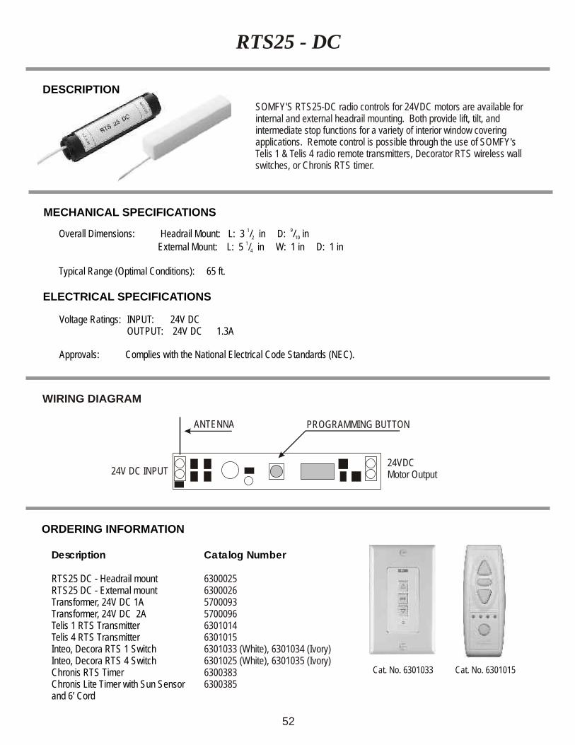
RTS25 - DC
DESCRIPTION
MECHANICAL SPECIFICATIONS
Voltage Ratings: INPUT: 24V DC OUTPUT: 24V DC 1.3A
Approvals: Complies with the National Electrical Code Standards (NEC).
ELECTRICAL SPECIFICATIONS
SOMFY'S RTS25-DC radio controls for 24VDC motors are available for internal and external headrail mounting. Both provide lift, tilt, and intermediate stop functions for a variety of interior window covering applications. Remote control is possible through the use of SOMFY's Telis 1 & Telis 4 radio remote transmitters, Decorator RTS wireless wall switches, or Chronis RTS timer.
1 9Overall Dimensions: Headrail Mount: L: 3 / in D: / in2 10
External Mount: L: 5 in W: 1 in D: 1 in Typical Range (Optimal Conditions): 65 ft.
1/4
WIRING DIAGRAM
PROGRAMMING BUTTON
24V DC INPUT24VDCMotor Output
ANTENNA
Description
RTS25 DC - Headrail mountRTS25 DC - External mountTransformer, 24V DC 1ATransformer, 24V DC 2A Telis 1 RTS Transmitter Telis 4 RTS Transmitter Inteo, Decora RTS 1 SwitchInteo, Decora RTS 4 Switch Chronis RTS TimerChronis Lite Timer with Sun Sensorand 6’ Cord
Catalog Number
6300025630002657000935700096630101463010156301033 (White), 6301034 (Ivory)6301025 (White), 6301035 (Ivory)63003836300385
ORDERING INFORMATION
Cat. No. 6301033 Cat. No. 6301015
52
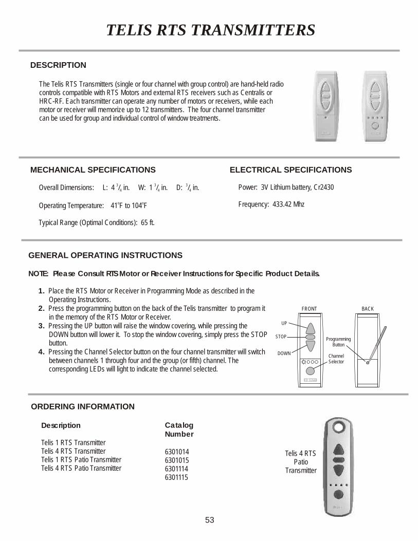
TELIS RTS TRANSMITTERS
DESCRIPTION
ORDERING INFORMATION
The Telis RTS Transmitters (single or four channel with group control) are hand-held radio controls compatible with RTS Motors and external RTS receivers such as Centralis or HRC-RF. Each transmitter can operate any number of motors or receivers, while each motor or receiver will memorize up to 12 transmitters. The four channel transmitter can be used for group and individual control of window treatments.
FRONT
UP
STOP
DOWNChannelSelector
ProgrammingButton
BACK
MECHANICAL SPECIFICATIONS
3 3 3 Overall Dimensions: L: 4 / in. W: 1 / in. D: / in. 4 4 4
o o Operating Temperature: 41 F to 104 F
Typical Range (Optimal Conditions): 65 ft.
ELECTRICAL SPECIFICATIONS
Power: 3V Lithium battery, Cr2430
Frequency: 433.42 Mhz
GENERAL OPERATING INSTRUCTIONS
NOTE: Please Consult RTS Motor or Receiver Instructions for Specific Product Details.
1. Place the RTS Motor or Receiver in Programming Mode as described in the Operating Instructions.
2. Press the programming button on the back of the Telis transmitter to program it in the memory of the RTS Motor or Receiver.
3. Pressing the UP button will raise the window covering, while pressing the DOWN button will lower it. To stop the window covering, simply press the STOP button.
4. Pressing the Channel Selector button on the four channel transmitter will switch between channels 1 through four and the group (or fifth) channel. The corresponding LEDs will light to indicate the channel selected.
53
Description
Telis 1 RTS Transmitter Telis 4 RTS Transmitter Telis 1 RTS Patio TransmitterTelis 4 RTS Patio Transmitter
Catalog Number
6301014630101563011146301115
Telis 4 RTS Patio
Transmitter
DESCRIPTION
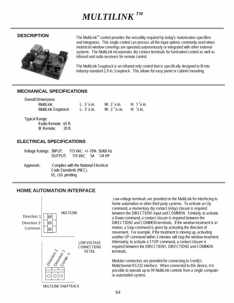
TMMULTILINK
TMThe MultiLink control provides the versatility required by today’s motorization specifiers and integrators. This single control can process all the input options commonly used when motorized window coverings are operated autonomously or integrated with other external systems. The MultiLink incorporates dry contact terminals for hard-wired control as well as infrared and radio receivers for remote control.
The MultiLink Snaptrack is an infrared only control that is specifically designed to fit into industry-standard 2.9 in. Snaptrack. This allows for easy panel or cabinet mounting.
MECHANICAL SPECIFICATIONS
Voltage Ratings: INPUT: 115 VAC +/- 10% 50/60 Hz OUTPUT: 115 VAC 5A 1/4 HP
Approvals: Complies with the National Electrical Code Standards (NEC).
UL, cUL pending
ELECTRICAL SPECIFICATIONS
Overall Dimensions:1 1 3
MultiLink: L: 3 /8 in. W: 2 /8 in. H: 1 /8 in.1 11 7
MultiLink Snaptrack: L: 3 /8 in. W: 2 /16 in. H: /8 in.
Typical Range: Radio Remote: 65 ft.IR Remote: 20 ft.
HOME AUTOMATION INTERFACE
Low voltage terminals are provided on the MultiLink for interfacing to home automation or other third party systems. To activate an Up command, a momentary dry contact (relay) closure is required between the DIRECTION1 input and COMMON. Similarly, to activate a Down command, a contact closure is required between the DIRECTION2 and COMMON terminals. If the window treatment is in motion, a Stop command is given by activating the direction of movement. For example, if the treatment is moving up, activating another UP command within 3 minutes will stop the window treatment. Alternately, to activate a STOP command, a contact closure is required between the DIRECTION1, DIRECTION2 and COMMON terminals.
Modular connectors are provided for connecting to Somfy’s Multichannel RS232 interface. When connected to this device, it is possible to operate up to 99 MultiLink controls from a single computer or automation system.
Direction 2
Direction 1
Common
LOW VOLTAGE CONNECTIONS
DETAIL
Dire
ctio
n 1
MULTILINK SNAPTRACK
MULTILINK
mC
omo
n
Dire
tion
2c
54
55
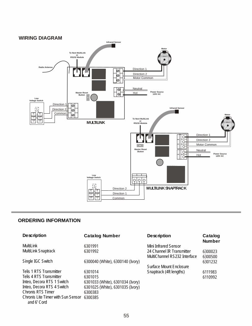
WIRING DIAGRAM
UP
DOWN
COM
UP
DOWN
COM
Direction 2
Hot
Neutral
Direction 1
Motor Common
Motor
Power Source120V AC
RR
Direction 2
Direction 1
Common
Low Voltage Switch
Master ResetButton
Infrared Sensor
Radio Antenna
To Next MultiLinkor
RS232 Module
Description
MultiLinkMultiLink Snaptrack
Single IGC Switch
Telis 1 RTS Transmitter Telis 4 RTS Transmitter Inteo, Decora RTS 1 SwitchInteo, Decora RTS 4 Switch Chronis RTS TimerChronis Lite Timer with Sun Sensor and 6’ Cord
Catalog Number
63019916301992
6300040 (White), 6300140 (Ivory)
630101463010156301033 (White), 6301034 (Ivory)6301025 (White), 6301035 (Ivory)63003836300385
ORDERING INFORMATION
Description
Mini Infrared Sensor24 Channel IR Transmitter MultiChannel RS232 Interface
Surface Mount EnclosureSnaptrack (4ft lengths)
Catalog Number
630002363005006301232
61119836110992
UP
DOWN
COM
UP
DOWN
COM
Direction 2
Hot
Neutral
Direction 1
Motor Common
Motor
Power Source120V AC
RR
Direction 2
Direction 1
Common
Low Voltage Switch
Master ResetButton
Infrared Sensor
To Next MultiLinkor
RS232 Module MULTILINK
MULTILINK SNAPTRACK

The IRS 300 provides infrared control for SOMFY's Concept 25 and LT28 motors. It is an addressable, multichannel receiver/control with lift and tilt capabilities. In addition, the IRS 300 provides inputs for both individual and master switches. Each individual IRS 300 can operate up to 3 motors as a group, depending on transformer rating.
IRS 300INFRARED CONTROL FOR DC MOTORS
MECHANICAL SPECIFICATIONS Voltage Rating: INPUT: 24 VDC
1 OUTPUT: 24 VDC, 750mA Overall Dimensions: L: 2 in. W: 3 in. D: 1 / in.4
per motor
Typical Range (Optimal Conditions): 20 ft. Approvals: Complies with the National Electrical Code (NEC) Standard
CE approvedELECTRICAL SPECIFICATIONS
RECOMMENDED TRANSFORMERS
MOTOR TYPE
LT28ALT28B
LV25-B44LV25-B64LW25-B83LT28-H2
1 MOTOR
570008857000955700095570009557000935700093
2 MOTOR
570009157000935700093570009357000965700096
3 MOTOR
570009157000935700096570009657000965700098
DESCRIPTION
TYPICAL APPLICATION
56
MASTERLINEIRS 300
MASTERSWITCH
IRS 300
TRANSFORMERTRANSFORMER
TO AC OUTLET TO AC OUTLET8 CHANNEL
TRANSMITTER
1
R 8 3T 0I
1 - 8 1 - 4 5 - 8
3
5
7
2
4
6
8
R .P OG
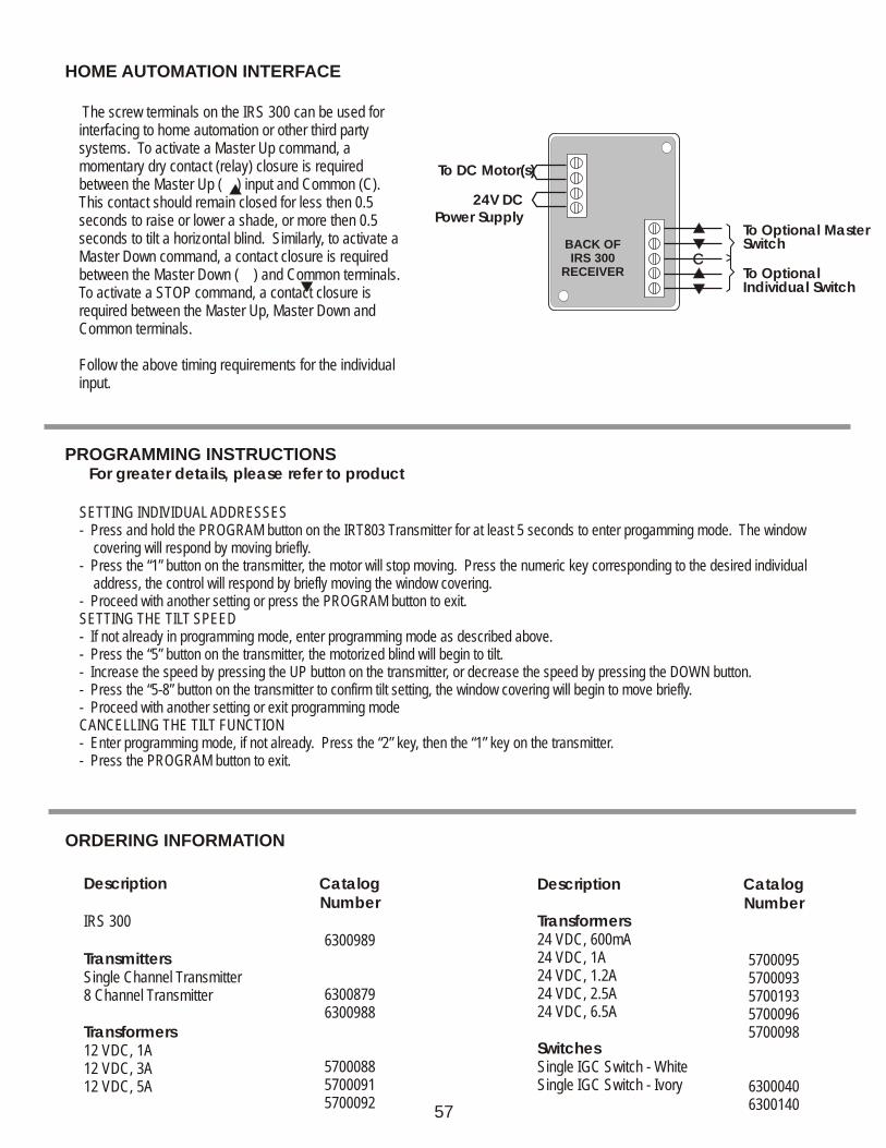
The screw terminals on the IRS 300 can be used for interfacing to home automation or other third party systems. To activate a Master Up command, a momentary dry contact (relay) closure is required between the Master Up ( ) input and Common (C). This contact should remain closed for less then 0.5 seconds to raise or lower a shade, or more then 0.5 seconds to tilt a horizontal blind. Similarly, to activate a Master Down command, a contact closure is required between the Master Down ( ) and Common terminals. To activate a STOP command, a contact closure is required between the Master Up, Master Down and Common terminals.
Follow the above timing requirements for the individual input.
Description
IRS 300
TransmittersSingle Channel Transmitter8 Channel Transmitter
Transformers12 VDC, 1A12 VDC, 3A12 VDC, 5A
Catalog Number
6300989
63008796300988
570008857000915700092
ORDERING INFORMATION
PROGRAMMING INSTRUCTIONS For greater details, please refer to product
HOME AUTOMATION INTERFACE
Description
24 VDC, 600mA
24 VDC, 2.5A24 VDC, 6.5A
SwitchesSingle IGC Switch - WhiteSingle IGC Switch - Ivory
Transformers
24 VDC, 1A24 VDC, 1.2A
Catalog Number
5700095
57000965700098
63000406300140
57000935700193
To DC Motor(s)
To Optional MasterSwitch
To OptionalIndividual Switch
24V DCPower Supply
BACK OF IRS 300
RECEIVERCC
57
SETTING INDIVIDUAL ADDRESSES- Press and hold the PROGRAM button on the IRT803 Transmitter for at least 5 seconds to enter progamming mode. The window covering will respond by moving briefly. - Press the “1” button on the transmitter, the motor will stop moving. Press the numeric key corresponding to the desired individual address, the control will respond by briefly moving the window covering.- Proceed with another setting or press the PROGRAM button to exit.SETTING THE TILT SPEED- If not already in programming mode, enter programming mode as described above.- Press the “5” button on the transmitter, the motorized blind will begin to tilt.- Increase the speed by pressing the UP button on the transmitter, or decrease the speed by pressing the DOWN button.- Press the “5-8” button on the transmitter to confirm tilt setting, the window covering will begin to move briefly.- Proceed with another setting or exit programming modeCANCELLING THE TILT FUNCTION- Enter programming mode, if not already. Press the “2” key, then the “1” key on the transmitter.- Press the PROGRAM button to exit.
SINGLE MOTOR REMOTE
DESCRIPTION
MECHANICAL SPECIFICATIONS
ELECTRICAL SPECIFICATIONS
1 1 1Overall Dimensions: Remote: L: 3 / in. W: 3 / in. D: 2 / in.2 4 4
3 3 Receiver: L: 3 in. W: 4 / in. D: 1 / in.4 8
Typical Range (Optimal Conditions): 75 ft.
Voltage Ratings:
INPUT: 120 VAC +/- 10%50/60 HzOUTPUT: 120 VAC 5A 1/4 HP
Fuse 5A 115/230 VAC
Approvals: Complies with the National Electrical Code (NEC) Standard, UR, CSA, and FCC.
58
Somfy’s Remote Control provides motor control from a distance through the use of radio technology. It is compatible with Stanley receivers and transmitters, so insect screens and garage doors can be operated from a single transmitter.
The Digital Remote features an input to lock out the controller. This feature prevents the motor from starting, which may cause damage to an open door or window. It also has dry-contact output capability for operating other devices, such as Somfy’s GCS-II.
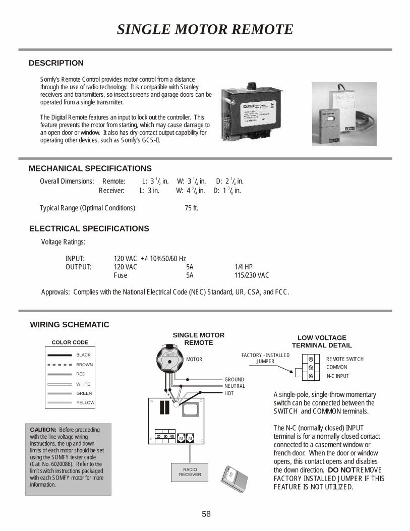
WIRING SCHEMATIC
SINGLE MOTORREMOTE
LOW VOLTAGETERMINAL DETAIL
RR
HOT
NEUTRAL
BROWN
BLACK
RED
WHITE
GREEN
YELLOW
MOTOR
GROUND
M M
COLOR CODE
RADIORECEIVER
CAUTION: Before proceeding with the line voltage wiring instructions, the up and down limits of each motor should be set using the SOMFY tester cable (Cat. No. 6020086). Refer to the limit switch instructions packaged with each SOMFY motor for more information.
REMOTE SWITCH
COMMON
N-C INPUT
A single-pole, single-throw momentary switch can be connected between the SWITCH and COMMON terminals.
The N-C (normally closed) INPUT terminal is for a normally closed contact connected to a casement window or french door. When the door or window opens, this contact opens and disables the down direction. DO NOT REMOVE FACTORY INSTALLED JUMPER IF THIS FEATURE IS NOT UTILIZED.
FACTORY - INSTALLEDJUMPER
ORDERING INFORMATION
Description
Standard Remote ControlRemote Controller 115 VAC (Control Only)
Single Motor Remote Control Kit(Control, Receiver, Transmitter)
Description
AccessoriesIndoor Digital KeypadOutdoor Digital KeypadSPST Momentary SwitchMomentary Outdoor Key Switch (FM, SM)2 Gang Electrical Box
59
Catalog Number
6300690
6300696
Catalog Number
6300739630074063000806120622, 61202125670323
Receivers/TransmittersPlug-in Single Channel Radio ReceiverSingle Channel Transmitter
Two Channel Transmitter
6300703630050863005076300509
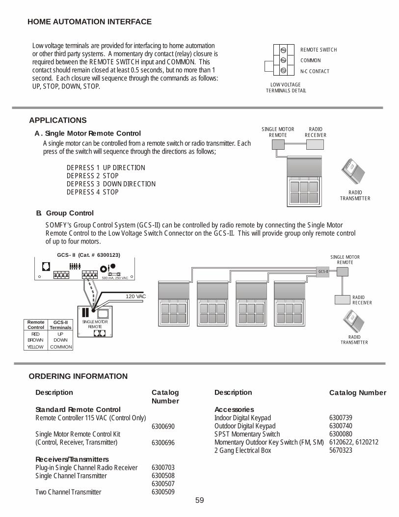
HOME AUTOMATION INTERFACE
REMOTE SWITCH
COMMON
N-C CONTACT
Low voltage terminals are provided for interfacing to home automation or other third party systems. A momentary dry contact (relay) closure is required between the REMOTE SWITCH input and COMMON. This contact should remain closed at least 0.5 seconds, but no more than 1 second. Each closure will sequence through the commands as follows: UP, STOP, DOWN, STOP. LOW VOLTAGE
TERMINALS DETAIL
SINGLE MOTOR REMOTE
RADIORECEIVER
RADIOTRANSMITTER
A . Single Motor Remote Control
A single motor can be controlled from a remote switch or radio transmitter. Each press of the switch will sequence through the directions as follows;
DEPRESS 1 UP DIRECTIONDEPRESS 2 STOPDEPRESS 3 DOWN DIRECTIONDEPRESS 4 STOP
APPLICATIONS
RADIOTRANSMITTER
SINGLE MOTOR REMOTE
RADIORECEIVER
GCS-II
B. Group Control
500 mA, 250 VAC
GCS - II (Cat. # 6300123)
SINGLE MOTORREMOTE
120 VAC
RemoteControl
GCS-IITerminals
RED UP
BROWN DOWN
YELLOW COMMON
SOMFY's Group Control System (GCS-II) can be controlled by radio remote by connecting the Single Motor Remote Control to the Low Voltage Switch Connector on the GCS-II. This will provide group only remote control of up to four motors.
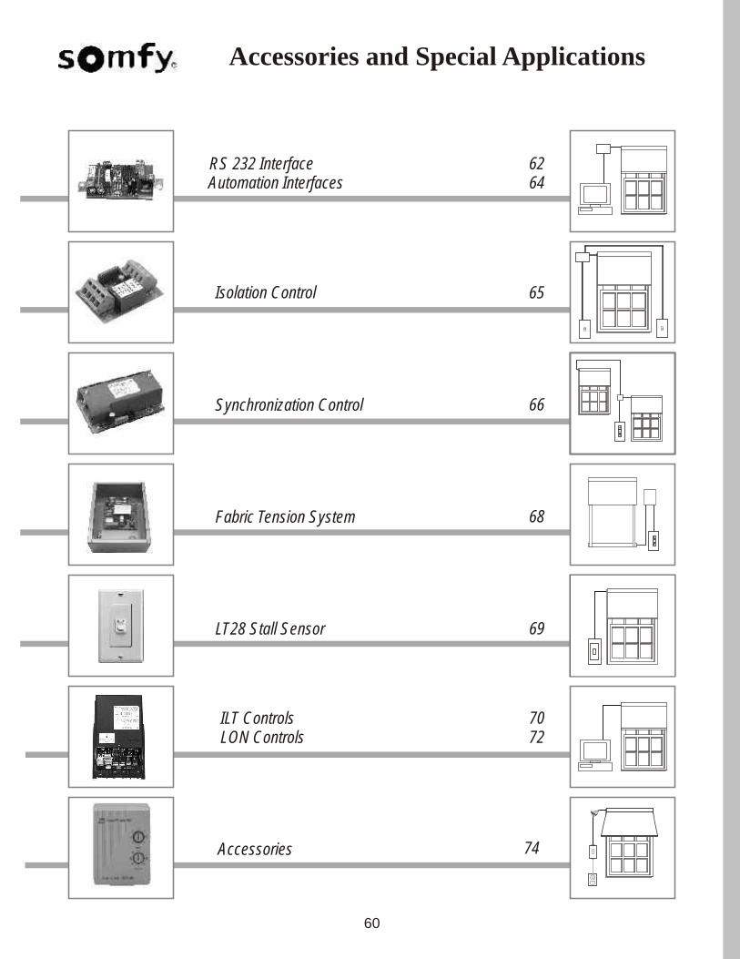
Isolation Control
Fabric Tension System
Accessories
LON ControlsILT Controls
Accessories and Special Applications
60
stop
65
74
7270
68
RS 232 Interface 62
Synchronization Controlstop
66
LT28 Stall Sensor 69
Automation Interfaces 64
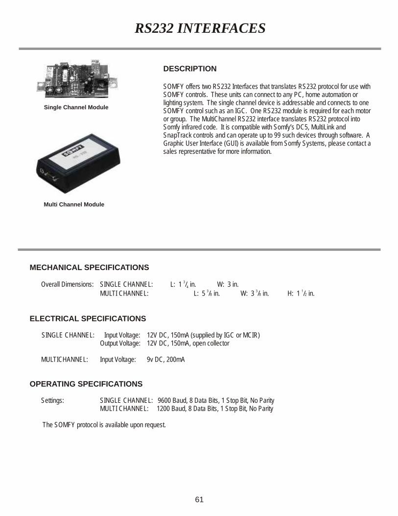
RS232 INTERFACES
DESCRIPTION SOMFY offers two RS232 Interfaces that translates RS232 protocol for use with SOMFY controls. These units can connect to any PC, home automation or lighting system. The single channel device is addressable and connects to one SOMFY control such as an IGC. One RS232 module is required for each motor or group. The MultiChannel RS232 interface translates RS232 protocol into Somfy infrared code. It is compatible with Somfy’s DC5, MultiLink and SnapTrack controls and can operate up to 99 such devices through software. A Graphic User Interface (GUI) is available from Somfy Systems, please contact a sales representative for more information.
MECHANICAL SPECIFICATIONS
3 Overall Dimensions: SINGLE CHANNEL: L: 1 / in. W: 3 in. 43 3 1
MULTI CHANNEL: L: 5 /8 in. W: 3 /8 in. H: 1 /2 in.
ELECTRICAL SPECIFICATIONS SINGLE CHANNEL: Input Voltage: 12V DC, 150mA (supplied by IGC or MCIR) Output Voltage: 12V DC, 150mA, open collector MULTICHANNEL: Input Voltage: 9v DC, 200mA
OPERATING SPECIFICATIONS
Settings: SINGLE CHANNEL: 9600 Baud, 8 Data Bits, 1 Stop Bit, No ParityMULTI CHANNEL: 1200 Baud, 8 Data Bits, 1 Stop Bit, No Parity
The SOMFY protocol is available upon request.
61
Single Channel Module
Multi Channel Module
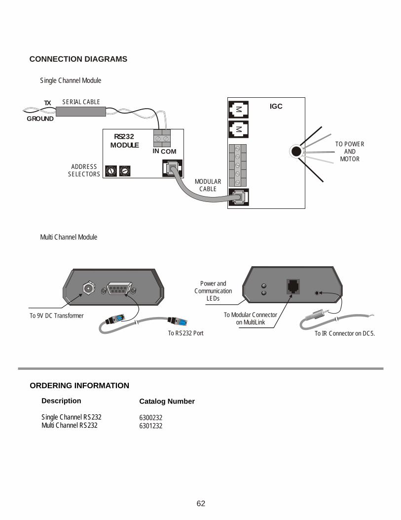
CONNECTION DIAGRAMS
MM
RS232MODULE
IGCTX
IN COM
GROUND
MODULAR CABLE
F0E
DC
BA 9
6
8 7
53
4
1 2 F 0E
DC
BA 9
6
8 7
53
4
1 2
SERIAL CABLE
ADDRESSSELECTORS
TO POWERAND
MOTOR
Single Channel Module
To 9V DC Transformer
To RS232 Port
Power andCommunication
LEDs
To Modular Connector on MultiLink
To IR Connector on DC5.
Multi Channel Module
62
Description
Single Channel RS232Multi Channel RS232
Catalog Number
63002326301232
ORDERING INFORMATION
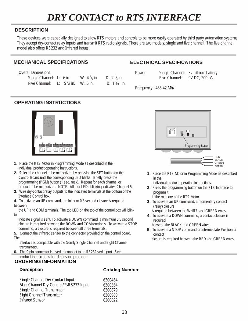
DRY CONTACT to RTS INTERFACEDESCRIPTION
These devices were especially designed to allow RTS motors and controls to be more easily operated by third party automation systems. They accept dry-contact relay inputs and transmit RTS radio signals. There are two models, single and five channel. The five channel model also offers RS232 and Infrared inputs.
MECHANICAL SPECIFICATIONS
Overall Dimensions: 1 1
Single Channel: L: 6 in. W: 4 / in. D: 2 / in. 4 43Five Channel: L: 5 /8 in. W: 5 in. D: 1 ¾ in.
ELECTRICAL SPECIFICATIONS
Power: Single Channel: 3v Lithium battery Five Channel: 9V DC, 200mA
Frequency: 433.42 Mhz
CH
AN
NE
L 1
UP
DO
WN
CO
M
CH
AN
NE
L 2
UP
DO
WN
CO
M
CH
AN
NE
L 3
UP
DO
WN
CO
M
CH
AN
NE
L 4
UP
DO
WN
CO
M
CH
AN
NE
L 5
UP
DO
WN
CO
M
SET PGM
Programming Button
1. Place the RTS Motor in Programming Mode as described in the
individual product operating instructions.2. Press the programming button on the RTS Interface to
program it in the memory of the RTS Motor. 3. To activate an UP command, a momentary contact
(relay) closure is required between the WHITE and GREEN wires.4. To activate a DOWN command, a contact closure is
required between the BLACK and GREEN wires.5. To activate a STOP command or Intermediate Position, a
contact closure is required between the RED and GREEN wires.
1. Place the RTS Motor in Programming Mode as described in the individual product operating instructions.2. Select the channel to be memorized by pressing the SET button on the Control Board until the corresponding LED blinks. Briefly press the programming (PGM) button (1 sec. max). Repeat for each channel or product to be memorized. NOTE: All four LEDs blinking indicates Channel 5. 3. Wire dry-contact relay outputs to the indicated terminals at the bottom of the
Interface Control box.4. To activate an UP command, a minimum 0.5 second closure is required between the UP and COM terminals. The top LED on the top of the control box will blink to indicate signal is sent. To activate a DOWN command, a minimum 0.5 second closure is required between the DOWN and COM terminals. To activate a STOP command, a closure is required between all three terminals.5. Connect the Infrared sensor to the connector provided on the control board. The Interface is compatible with the Somfy Single Channel and Eight Channel transmitters.6. The 9 pin connector is used to connect to an RS232 serial port. See product instructions for details on protocol.
OPERATING INSTRUCTIONS
REDBLACKGREENWHITE
Description
Single Channel Dry-Contact Input Multi Channel Dry-Contact/IR/RS232 InputSingle Channel TransmitterEight Channel TransmitterInfrared Sensor
Catalog Number
63004546300554630087963009896300022
ORDERING INFORMATION
63
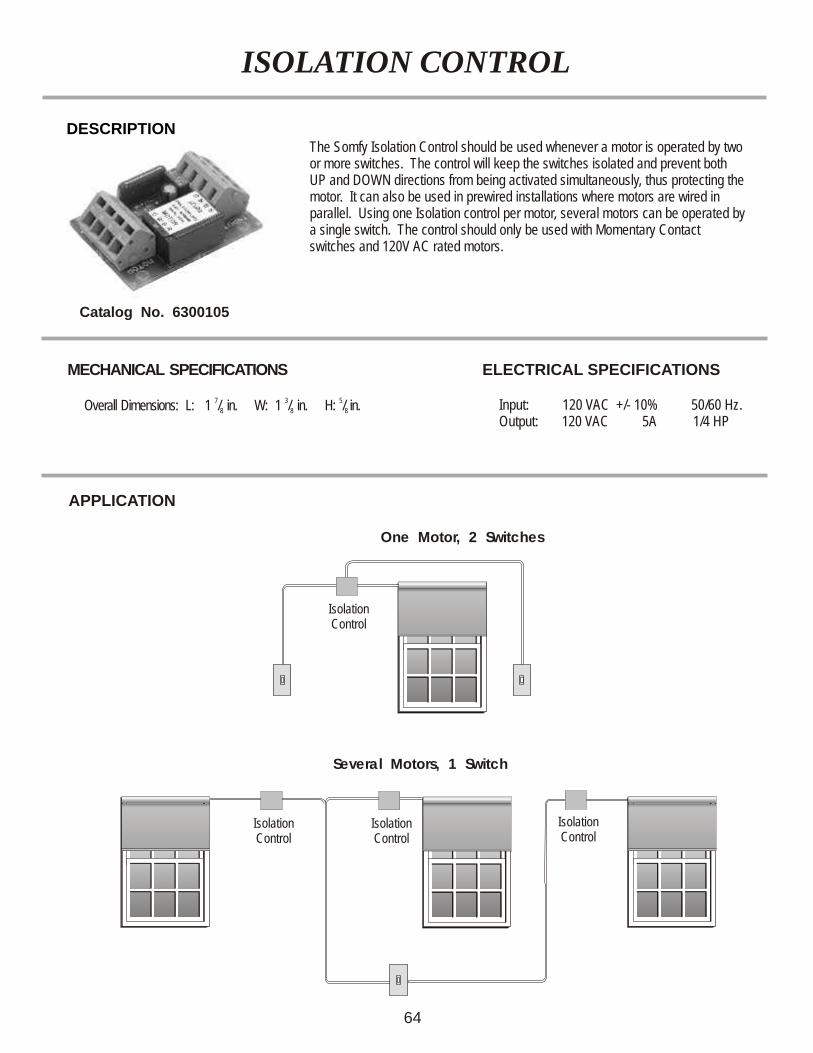
The Somfy Isolation Control should be used whenever a motor is operated by two or more switches. The control will keep the switches isolated and prevent both UP and DOWN directions from being activated simultaneously, thus protecting the motor. It can also be used in prewired installations where motors are wired in parallel. Using one Isolation control per motor, several motors can be operated by a single switch. The control should only be used with Momentary Contact switches and 120V AC rated motors.
ISOLATION CONTROL
DESCRIPTION
ELECTRICAL SPECIFICATIONS
Input: 120 VAC +/- 10% 50/60 Hz. Output: 120 VAC 5A 1/4 HP
MECHANICAL SPECIFICATIONS
7 3 5 Overall Dimensions: L: 1 / in. W: 1 / in. H: / in.8 8 8
Catalog No. 6300105
APPLICATION
Several Motors, 1 Switch
Isolation Control
One Motor, 2 Switches
Isolation Control
Isolation Control
Isolation Control
64
SYNCHRONIZING CONTROL
DESCRIPTION
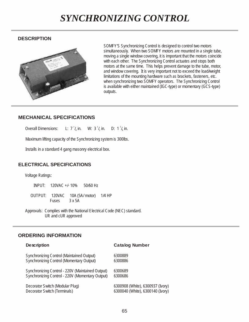
SOMFY'S Synchronizing Control is designed to control two motors simultaneously. When two SOMFY motors are mounted in a single tube, moving a single window covering, it is important that the motors coincide with each other. The Synchronizing Control actuates and stops both motors at the same time. This helps prevent damage to the tube, motor, and window covering. It is very important not to exceed the load/weight limitations of the mounting hardware such as brackets, fasteners, etc. when synchronizing two SOMFY operators. The Synchronizing Control is available with either maintained (IGC-type) or momentary (GCS-type) outputs.
MECHANICAL SPECIFICATIONS
1 1 7 Overall Dimensions: L: 7 / in. W: 3 / in. D: 1 / in.4 2 8
Maximum lifting capacity of the Synchronizing system is 300lbs. Installs in a standard 4 gang masonry electrical box.
ELECTRICAL SPECIFICATIONS
Voltage Ratings:
INPUT: 120VAC +/- 10% 50/60 Hz OUTPUT: 120VAC 10A (5A/ motor) 1/4 HP Fuses 3 x 5A
Approvals: Complies with the National Electrical Code (NEC) standard. UR and cUR approved
ORDERING INFORMATION
Description Catalog Number
Synchronizing Control (Maintained Output) 6300889Synchronizing Control (Momentary Output) 6300886
Synchronizing Control - 220V (Maintained Output) 6300689Synchronizing Control - 220V (Momentary Output) 6300686
Decorator Switch (Modular Plug) 6300908 (White), 6300937 (Ivory)Decorator Switch (Terminals) 6300040 (White), 6300140 (Ivory)
65
POWER
BLACK
WHITE
GREEN
MOTOR1 MOTOR2
WHITE WHITE
GREEN GREEN
RED
REDBLACK
BLACK
SYNCHRO
BLACK
WHITE
RED
GREEN
BROWN
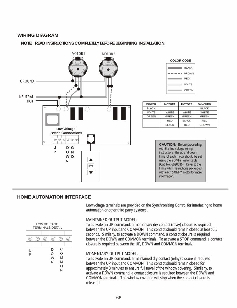
WIRING DIAGRAM
HOME AUTOMATION INTERFACE
BROWN
BLACK
RED
WHITE
GREEN
COLOR CODE
GROUND
NEUTRALHOT
RR
RR
STOPSTOP
Low VoltageSwitch Connections
NOTE: READ INSTRUCTIONS COMPLETELY BEFORE BEGINNING INSTALLATION.
MOTOR1 MOTOR2
U D GP O N
W D N
CAUTION: Before proceeding with the line voltage wiring instructions, the up and down limits of each motor should be set using the SOMFY tester cable (Cat. No. 6020086). Refer to the limit switch instructions packaged with each SOMFY motor for more information.
Low voltage terminals are provided on the Synchronizing Control for interfacing to home automation or other third party systems.
MAINTAINED OUTPUT MODEL:To activate an UP command, a momentary dry contact (relay) closure is required between the UP input and COMMON. This contact should remain closed at least 0.5 seconds. Similarly, to activate a DOWN command, a contact closure is required between the DOWN and COMMON terminals. To activate a STOP command, a contact closure is required between the UP, DOWN and COMMON terminals.
MOMENTARY OUTPUT MODEL:To activate an UP command, a maintained dry contact (relay) closure is required between the UP input and COMMON. This contact should remain closed for approximately 3 minutes to ensure full travel of the window covering. Similarly, to activate a DOWN command, a contact closure is required between the DOWN and COMMON terminals. The window covering will stop when the contact closure is released.
LOW VOLTAGE TERMINALS DETAIL
UP
COMMON
DOWN
66
FABRIC TENSION SYSTEM CONTROL (FTS)
ORDERING INFORMATION
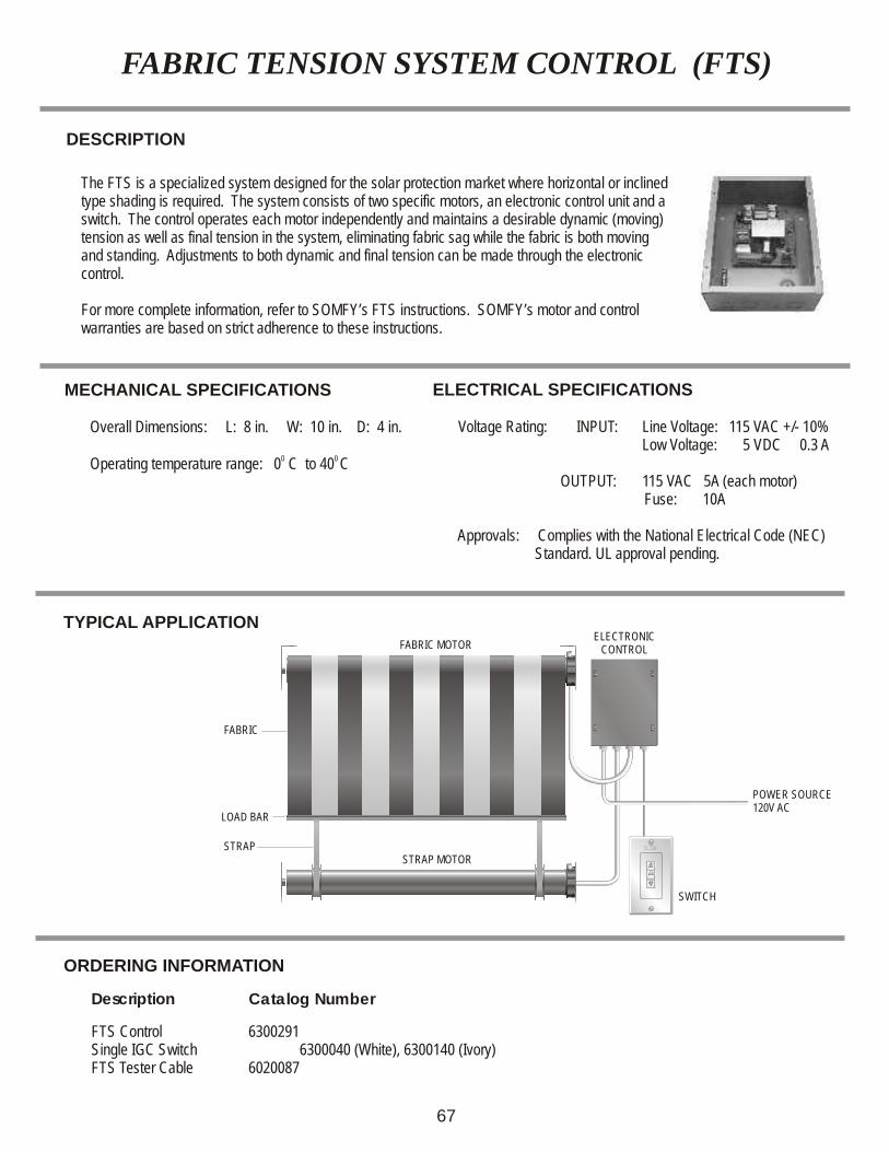
TYPICAL APPLICATION
The FTS is a specialized system designed for the solar protection market where horizontal or inclined type shading is required. The system consists of two specific motors, an electronic control unit and a switch. The control operates each motor independently and maintains a desirable dynamic (moving) tension as well as final tension in the system, eliminating fabric sag while the fabric is both moving and standing. Adjustments to both dynamic and final tension can be made through the electronic control.
For more complete information, refer to SOMFY’s FTS instructions. SOMFY’s motor and control warranties are based on strict adherence to these instructions.
MECHANICAL SPECIFICATIONS
Overall Dimensions: L: 8 in. W: 10 in. D: 4 in.
0 0 Operating temperature range: 0 C to 40 C
FABRIC
FABRIC MOTORELECTRONIC
CONTROL
POWER SOURCE120V AC
SWITCH
STRAPSTRAP MOTOR
LOAD BAR
Description Catalog Number
FTS Control 6300291Single IGC Switch 6300040 (White), 6300140 (Ivory)FTS Tester Cable 6020087
67
DESCRIPTION
ELECTRICAL SPECIFICATIONS
Voltage Rating: INPUT: Line Voltage: 115 VAC +/- 10% Low Voltage: 5 VDC 0.3 A
OUTPUT: 115 VAC 5A (each motor) Fuse: 10A
Approvals: Complies with the National Electrical Code (NEC) Standard. UL approval pending.
ORDERING INFORMATION
Description Catalog Number
Decorator Stall Sensor 6300907Stall Sensor w/Enclosure 6300120
LT28 STALL SENSOR
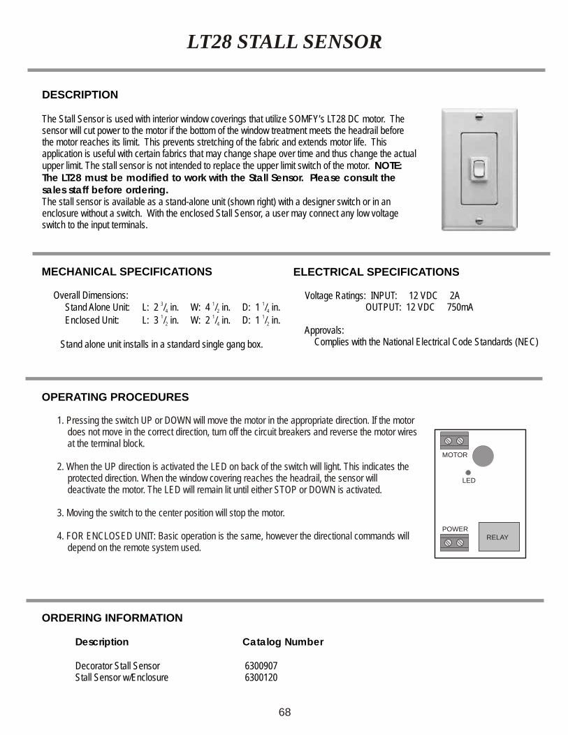
1. Pressing the switch UP or DOWN will move the motor in the appropriate direction. If the motor does not move in the correct direction, turn off the circuit breakers and reverse the motor wires at the terminal block.
2. When the UP direction is activated the LED on back of the switch will light. This indicates the protected direction. When the window covering reaches the headrail, the sensor will deactivate the motor. The LED will remain lit until either STOP or DOWN is activated.
3. Moving the switch to the center position will stop the motor.
4. FOR ENCLOSED UNIT: Basic operation is the same, however the directional commands will depend on the remote system used.
MOTOR
POWERRELAY
LED
68
DESCRIPTION
The Stall Sensor is used with interior window coverings that utilize SOMFY’s LT28 DC motor. The sensor will cut power to the motor if the bottom of the window treatment meets the headrail before the motor reaches its limit. This prevents stretching of the fabric and extends motor life. This application is useful with certain fabrics that may change shape over time and thus change the actual upper limit. The stall sensor is not intended to replace the upper limit switch of the motor. NOTE: The LT28 must be modified to work with the Stall Sensor. Please consult the sales staff before ordering.The stall sensor is available as a stand-alone unit (shown right) with a designer switch or in an enclosure without a switch. With the enclosed Stall Sensor, a user may connect any low voltage switch to the input terminals.
MECHANICAL SPECIFICATIONS
Overall Dimensions: Stand Alone Unit: L: 2 in. W: 4 in. D: 1 in.
Enclosed Unit: L: 3 in. W: 2 in. D: 1 in.
Stand alone unit installs in a standard single gang box.
3 1 1/ / /4 2 41 1 1/ / /2 4 2
OPERATING PROCEDURES
ELECTRICAL SPECIFICATIONS
Voltage Ratings: INPUT: 12 VDC 2A OUTPUT: 12 VDC 750mA
Approvals: Complies with the National Electrical Code Standards (NEC)
DESCRIPTION
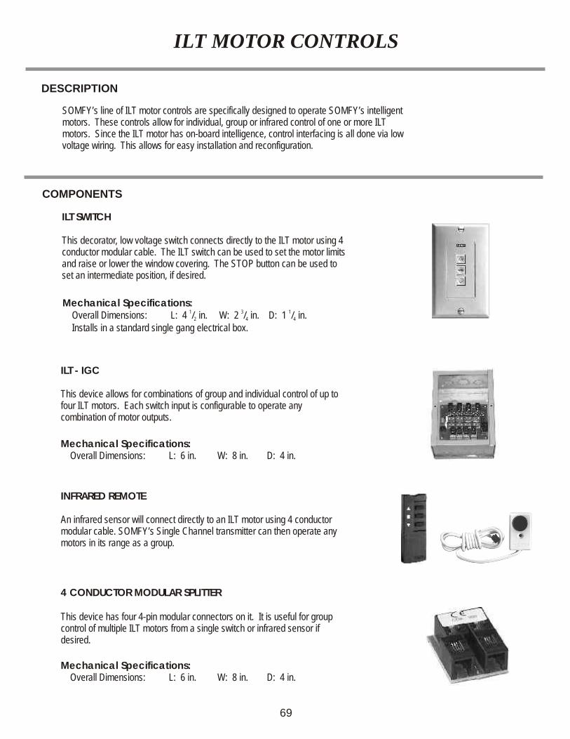
SOMFY’s line of ILT motor controls are specifically designed to operate SOMFY’s intelligent motors. These controls allow for individual, group or infrared control of one or more ILT motors. Since the ILT motor has on-board intelligence, control interfacing is all done via low voltage wiring. This allows for easy installation and reconfiguration.
Mechanical Specifications: 1 3 1 Overall Dimensions: L: 4 / in. W: 2 / in. D: 1 / in.2 4 4
Installs in a standard single gang electrical box.
Mechanical Specifications: L: 6 in. W: 8 in. D: 4 in. Overall Dimensions:
Mechanical Specifications: L: 6 in. W: 8 in. D: 4 in. Overall Dimensions:
COMPONENTS
ILT SWITCH
This decorator, low voltage switch connects directly to the ILT motor using 4 conductor modular cable. The ILT switch can be used to set the motor limits and raise or lower the window covering. The STOP button can be used to set an intermediate position, if desired.
ILT - IGC
This device allows for combinations of group and individual control of up to four ILT motors. Each switch input is configurable to operate any combination of motor outputs.
4 CONDUCTOR MODULAR SPLITTER
This device has four 4-pin modular connectors on it. It is useful for group control of multiple ILT motors from a single switch or infrared sensor if desired.
INFRARED REMOTE
An infrared sensor will connect directly to an ILT motor using 4 conductor modular cable. SOMFY’s Single Channel transmitter can then operate any motors in its range as a group.
ILT MOTOR CONTROLS
69
ORDERING INFORMATION
DescriptionDescription Catalog NumberCatalog Number
4 Conductor Modular SplitterSingle Channel Transmitter4 Pin Modular Connector Crimp Tool
ILT SwitchILT - IGC ControlInfrared Sensor for ILT
551049163008794600020
6300053 (White), 6300054 (Ivory)63007216150477
120 VAC
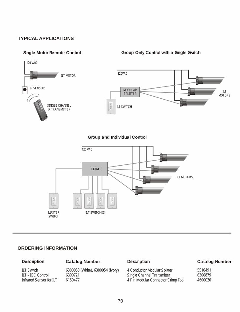
ILT-IGC
MASTERSWITCH
ILT SWITCHES
ILT MOTORS
YFOS
M
120 VAC
ILT MOTOR
IR SENSOR
SINGLE CHANNELIR TRANSMITTER
TYPICAL APPLICATIONS
120VAC
ILT SWITCH
ILTMOTORS
MODULAR SPLITTER
Group and Individual Control
Group Only Control with a Single SwitchSingle Motor Remote Control
70
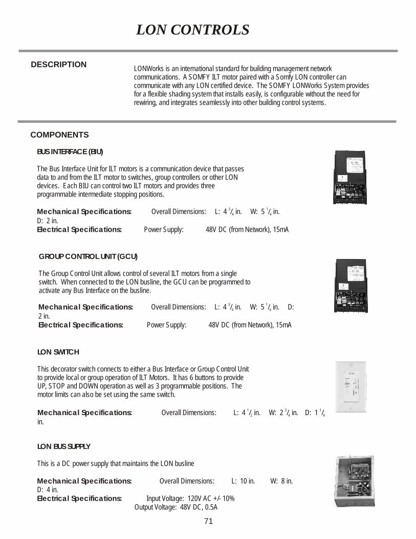
DESCRIPTIONLONWorks is an international standard for building management network communications. A SOMFY ILT motor paired with a Somfy LON controller can communicate with any LON certified device. The S LONWorks System provides for a flexible shading system that installs easily, is configurable without the need for rewiring, and integrates seamlessly into other building control systems.
OMFY
Mechanical Specifications: 3 1Overall Dimensions: L: 4 / in. W: 5 / in. 4 4
D: 2 in.Electrical Specifications: Power Supply: 48V DC (from Network), 15mA
Mechanical Specifications: 3 1Overall Dimensions: L: 4 / in. W: 5 / in. D: 4 4
2 in.Electrical Specifications: Power Supply: 48V DC (from Network), 15mA
Mechanical Specifications: L: 10 in. W: 8 in. D: 4 in.
Overall Dimensions:
Electrical Specifications: Input Voltage: 120V AC +/- 10% Output Voltage: 48V DC, 0.5A
COMPONENTS
BUS INTERFACE (BIU)
The Bus Interface Unit for ILT motors is a communication device that passes data to and from the ILT motor to switches, group controllers or other LON devices. Each BIU can control two ILT motors and provides three programmable intermediate stopping positions.
GROUP CONTROL UNIT (GCU)
The Group Control Unit allows control of several ILT motors from a single switch. When connected to the LON busline, the GCU can be programmed to activate any Bus Interface on the busline.
LON BUS SUPPLY
This is a DC power supply that maintains the LON busline
LON SWITCH
This decorator switch connects to either a Bus Interface or Group Control Unit to provide local or group operation of ILT Motors. It has 6 buttons to provide UP, STOP and DOWN operation as well as 3 programmable positions. The motor limits can also be set using the same switch.
LON CONTROLS
Mechanical Specifications: 1 3 1Overall Dimensions: L: 4 / in. W: 2 / in. D: 1 / 2 4 4
in.
71
ORDERING INFORMATION
Description Catalog Number
LON SwitchBus Interface ControlGroup Control UnitBus Supply
6301004 (White), 6301005 (Ivory)630100163010026301003
72
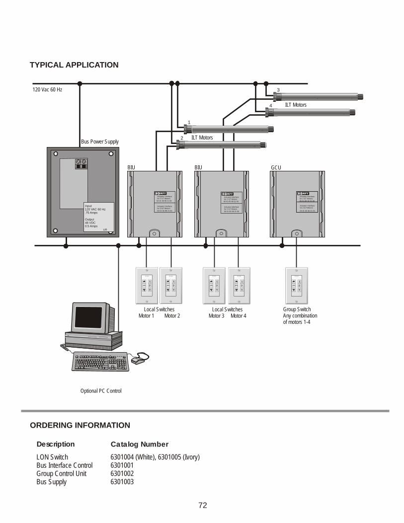
TYPICAL APPLICATION
Actuator Interfacefor 2 ILT Motors
Actuator Interfacefor 2 ILT Motors
00 01 65 36 21 00
00 01 65 36 21 00
Input120 VAC 60 Hz.75 Amps
Output48 VDC0.5 Amps
UR
Bus Power Supply
GCU
120 Vac 60 Hz
Actuator Interfacefor 2 ILT Motors
Actuator Interfacefor 2 ILT Motors
00 01 65 98 21 65
00 01 65 98 21 65
BIU
ILT Motors
Local SwitchesMotor 1 Motor 2
Optional PC Control
BIU
ILT Motors
Group SwitchAny combination of motors 1-4
3
4
1
2
Local SwitchesMotor 3 Motor 4
1
2
3
1
2
3
1
2
3
1
2
3
1
2
3
Actuator Interfacefor 2 ILT Motors
Actuator Interfacefor 2 ILT Motors
00 01 65 98 21 65
00 01 65 98 21 65
SOMFY ACCESSORIES
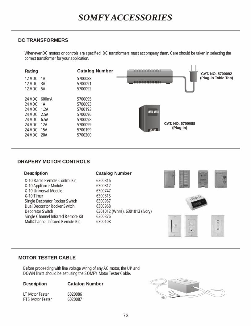
Whenever DC motors or controls are specified, DC transformers must accompany them. Care should be taken in selecting the correct transformer for your application.
Rating
DC TRANSFORMERS
Catalog Number
12 VDC 1A12 VDC 3A12 VDC 5A
24 VDC 600mA24 VDC 1A24 VDC 1.2A24 VDC 2.5A24 VDC 6.5A24 VDC 12A24 VDC 15A24 VDC 20A
570008857000915700092
57000955700093570019357000965700098570009957001995700200
Before proceeding with line voltage wiring of any AC motor, the UP and DOWN limits should be set using the SOMFY Motor Tester Cable.
Description Catalog Number
LT Motor Tester 6020086FTS Motor Tester 6020087
DRAPERY MOTOR CONTROLS
MOTOR TESTER CABLE
X-10 Radio Remote Control KitX-10 Appliance Module X-10 Universal Module X-10 TimerSingle Decorator Rocker SwitchDual Decorator Rocker SwitchDecorator SwitchSingle Channel Infrared Remote KitMultiChannel Infrared Remote Kit
6300816630081263007476300815630096763009686301012 (White), 6301013 (Ivory)63008766300108
Description Catalog Number
73
CAT. NO. 5700092(Plug-in Table Top)
CAT. NO. 5700088(Plug-in)
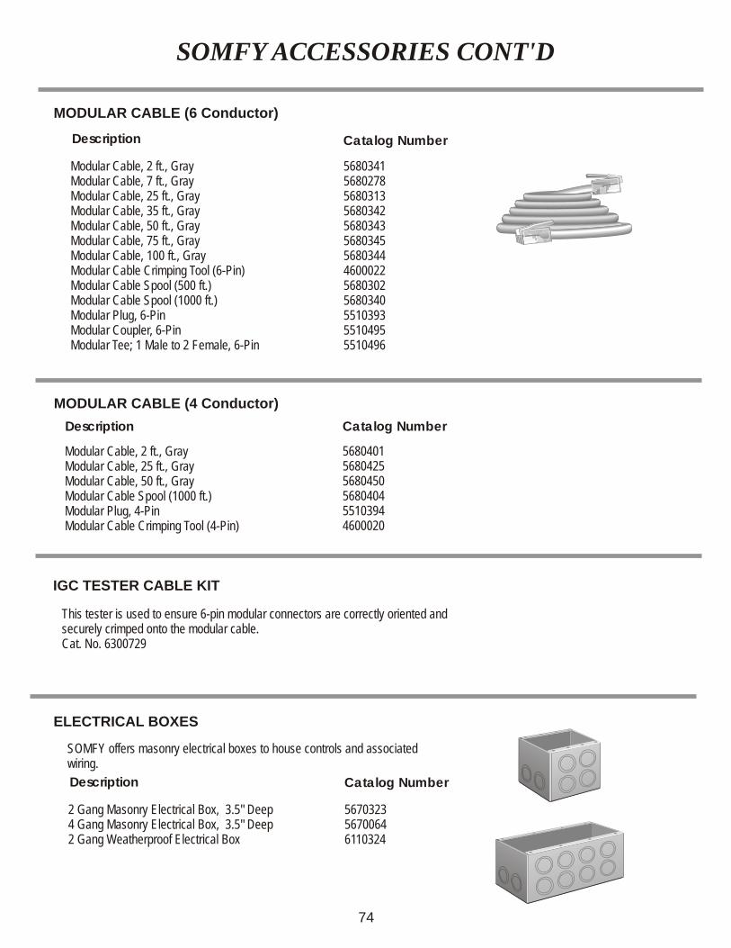
SOMFY ACCESSORIES CONT'D
This tester is used to ensure 6-pin modular connectors are correctly oriented and securely crimped onto the modular cable. Cat. No. 6300729
SOMFY offers masonry electrical boxes to house controls and associated wiring.
Description
Description
Description
IGC TESTER CABLE KIT
ELECTRICAL BOXES
MODULAR CABLE (6 Conductor)
MODULAR CABLE (4 Conductor)
Catalog Number
Catalog Number
Catalog Number
Modular Cable, 2 ft., GrayModular Cable, 7 ft., GrayModular Cable, 25 ft., GrayModular Cable, 35 ft., GrayModular Cable, 50 ft., GrayModular Cable, 75 ft., GrayModular Cable, 100 ft., GrayModular Cable Crimping Tool (6-Pin)Modular Cable Spool (500 ft.)Modular Cable Spool (1000 ft.)Modular Plug, 6-PinModular Coupler, 6-PinModular Tee; 1 Male to 2 Female, 6-Pin
Modular Cable, 2 ft., GrayModular Cable, 25 ft., GrayModular Cable, 50 ft., GrayModular Cable Spool (1000 ft.)Modular Plug, 4-PinModular Cable Crimping Tool (4-Pin)
2 Gang Masonry Electrical Box, 3.5" Deep4 Gang Masonry Electrical Box, 3.5" Deep2 Gang Weatherproof Electrical Box
5680341568027856803135680342568034356803455680344460002256803025680340551039355104955510496
568040156804255680450568040455103944600020
567032356700646110324
74
INDEX
CentralisChronis RTS TimerComfort Control
DC-5 ControlDC TransformersDecorator RTS SwitchDecorator AC Switches DC Switches Comfort Control IGC Switch
TM Somfy-MaticDigital KeypadDrapery Motor ControlsDry Contact to RTS Interface
Electrical BoxesEolis Wind ControlEolis ReceiverEolis 24V RTS Sensor
FTS Control
GCS-II
IGCIGC-IIIGC/3N1IGC-II/3N1IGC-DCIGC SwitchIGC Sub-Group ControlIGC Tester Cable
Isolation ControlILT-IGCILT SwitchInfrared SwitchIntelliS TimerIRS 300
Key Switch
LON ControlsLT28 Stall Sensor
Modular CableModulineMotor Tester Cable
TMMultiLink
Outdoor Plug-in Switch
RTS25-DCRTS 24V SensorsRTS SwitchRS232 Interfaces
Single Motor Remote Soliris ReceiverSoliris RTS Sensors
TMSomfy-MaticSub-Group ControlSynchronizing Control
Telis 1 & Telis 4 RTS TransmittersTelis Soliris and Telis Soliris Patio Transmitters
501640
247415
99
401338117464
75424348
68
26
2831283122133475
657070191756
12
7269
75357454
10
52481562
584548383466
53
47