Embed Size (px)
Citation preview
Decoupling State from Control inSoftware-Defined Networking
Alberto Rodriguez-Natal
Advisor: Albert Cabellos-Aparicio, PhD
Co-Advisor: Fabio Maino, PhD
Department of Computer ArchitectureTechnical University of Catalonia
This dissertation is submitted in partial fulfillment of the requirements for thedegree of
Doctor of Philosophy in Computer Science
July 2016


To my parents, to my sisterand to Andrea,
of course


“This is how you do it: you sit down at the keyboardand you put one word after another until it’s done.
It’s that easy, and that hard.”- Neil Gaiman


Acknowledgements
I have always thought that the acknowledgments section is the most important part of a thesisfor two reasons. First because you can find the research elsewhere, but you can only findthe acknowledgments here. Second because while the research evolves and the results geteventually obsoleted, the people you meet along the way remain. Therefore, I have beenthinking on what to put in this section for a long time. However, now that I am finally writing itdown I believe that I am making no justice to the people mentioned here. I can not find thewords to express the gratitude I feel towards them. What follows is only a humble attempt.
As it should be, the first lines are for my advisor, Albert Cabellos. Exceptional researcher,mentor and individual. With so many PhD advisors out there, I consider myself fortunate forhaving ended up under his supervision. His clear vision, endless motivation and pragmatismdrove me through the most challenging periods of this thesis. Thanks also for always givingme honest feedback, even when I was not going to like it. However, for what I must thank himmost is for his advice beyond what concerns research. His down-to-earth recommendations andlife pro tips came really handy countless times. For those I am as thankful as for his researchguidance. Thanks also for being a proficient geek with whom exchange obscure references onmovies and comics. Unfortunately, at the time of this writing, determining who outperformsthe other on geek knowledge requires further investigation and remains as an open question.
Closely after comes my deep gratitude to my co-advisor, Fabio Maino. My honest apprecia-tion to him, who believed in my ability from the very beginning and encouraged me with soundtrust even when I hesitated. Thanks for being a guide to the inner dynamics of the industry andfor sharing curated knowledge with a newcomer. Thanks also for periodically giving me thechance to showcase my work to all sorts of audiences, but specially for doing so with solidconfidence in the successful outcome. I will be eternally indebted to Fabio for sponsoring myresearch and for offering me the opportunity to grow professionally, both during my thesisand afterwards. Thanks also for that conversation we once had in our way to the airport. Iremember vividly the counseling I received that day.
Let me also express my appreciation to the faculty members of the CBA research group atUPC. First, thanks to professors Jordi Domingo-Pascual and Josep Solé-Pareta, for guiding meduring my first steps as a researcher and for having been a source of advice since then. Thanks

viii
also to Davide Careglio, for the shared sense of humor and for taking me in those trips to myfirst project meetings. Finally, thanks to Pere Barlet for his always clever analysis and for thequality feedback provided at different points of my research.
My deep gratitude goes too to some members of the industry that inspired part of thisthesis. First of all to Sharon Barkai, for being a modern patron of the arts and the greatestexpert I know on combining networks and databases. My great appreciation to Sharon forcompletely changing my view on SDN and for being a great source of inspiration for this thesis.Sharon was the one who coined the idea of "global knowledge, local decisions", and Chapter 4was only possible thanks to him (kudos also to the rest of the great guys from ConteXtream:Ariel Noy, Ajay Sahai, Gideon Kaempfer, and the others). My most special thanks also toDino Farinacci, one of the fathers of LISP and engineer beyond compare. Capable, like noone else, of discussing both high-level architectural abstractions and bit-level details of theimplementation. I greatly appreciate those technical discussions on all things LISP, and ingeneral all the help provided over these years. Finally, my honest gratitude to David Meyer,truly visionary in the networking field, for sharing his vision. Thanks to Dave for always beingglad to engage on discussions on the future of networking, and for giving me a hand wheneverI needed it.
My sincere appreciation also to those LISP experts at Cisco. First and foremost to VinaErmagan, one of the major driving forces of this thesis. Vina’s talent for team building andgracious management were hugely appreciated when we were struggling to make it throughdeadlines. I could not thank her enough for these years of tireless support and guidance, onthis thesis and beyond. Her hard work and sharp advice truly shaped this research. My greatgratitude as well to Marc Portolés, who saved me on my first visit to the bay area and made thestay much more enjoyable. For that, I owe him countless beers. Thanks also for being such apassionate researcher and for dragging me into those creative technical discussions. Finally, ahuge thank you to Darrel Lewis for his always realistic technical advice, to Preethi Natarajanfor those early days of research on LISP-MN and to Vasileios Lakafosis for all his help withLISPmob.
I could not go without mentioning those months spent in Tokyo working at the laboratoryof Professor Yusheng Ji. Among all the great experiences that this thesis has granted me,I remember my stay in Japan as one of the best. My deep gratitude to Prof. Ji as well forgiving me a different perspective on my research. Her deep knowledge and multidisciplinaryexperience truly completed my work. Thanks also to Kien Nguyen for his practical advice onhow to survive in Tokyo and for those discussions about OpenFlow in the coffee room. Thanksto both for keep supporting me in the present day, long after my internship ended.

ix
A special note also to those I met via the IETF. A huge thanks to Luigi Iannone and DamienSaucez for the discussions on LISP and for making those IETF meetings more interesting.Thanks as well to Joel Halpern for sharing his technical wisdom and enlightening me on theintricate mechanisms of the IETF. Thanks also to Diego López for sharing his perspective onSDN, and for -unbelievably- always being present in all conferences I go.
A final mention to the people who lived with me in the D6-008 office. First to Florin Coras,who is ultimately the one to blame for this thesis. Shall I had not listened to him, I would havenot ended up doing a PhD with Albert and Fabio. Fortunately enough, I trusted his word backthen. Sorry for all the silly jokes during these years Florin, it is just my way to pay you back.Thanks as well to Loránd Jakab, who guided me during the beginning of my research. Hegave me right on the spot technical advices at that time and continues to do so today. Thanksalso to Albert Mestres, Sergi Abadal, Raül Gómez and Valentín Carela for the lunches andthe fun. I could not ask for better people to share an office with. Finally, my most deep andsincere gratitude to Albert López, an extraordinary research engineer but also a good friend.His rigorous work, methodical testing, and continuous contributions (often behind the scenes)can not be thanked enough. May these lines serve to give him part of the credit he deserves.Gràcies Albert!.
To conclude, I would like to acknowledge the funding that made this thesis possible. Thanksto Cisco Systems for their generosity supporting this research and to the Spanish Ministry ofEducation, Culture and Sport for supporting me trough scholarship FPU2012/01137.
A nivel personal me gustaría agradecer a mis compañeras de piso, Raquel y María, poraguantarme estos últimos años y en especial estos últimos meses. Sé que a veces no ha sidofácil. Gracias también a toda esa gente que lleva años on fire y a todos los presentes (físicamenteo no) en ese 28 de mayo. A todos ellos perdón por no haber podido estar en cafés, partidas ycervezas. Sabéis que os quiero a todos, pero la tesis siempre fue muy celosa.
Quiero dar las gracias de manera especial a mi familia. A mis padres, por darme todo suapoyo durante estos años, pero sobretodo porque nunca dudaron. Por ellos he llegado hastaaquí y por ellos ahora tengo que seguir adelante. Perdón por irme, pero gracias por entenderlo.Gracias también a mi hermana Laura, por todas las llamadas que le debo. Siento que hayastenido que ser hija única, pero estoy orgulloso de como has sabido salir adelante.
Las últimas palabras, por supuesto, son para Andrea. Para ella, a quien no hizo faltaexplicarle lo que era el índice JCR. Para ella, por todas las noches que tuvo que dormir con laluz encendida. Para ella, por estar tan loca como para acompañarme en la aventura que empiezadonde acaba este doctorado. Para ella, gracias.

Abstract
Software-Defined Networking (SDN) arose as a solution to address the limitations of traditionalnetworking. In SDN networks, the control-plane is decoupled from the data-plane devicesand logically centralized in a new network element, the SDN controller. SDN enables easiernetwork operation and allows forwarding devices and control logic to evolve independently.The centralization of the control permits to have a global view of the network and act on it as awhole, but at the same time requires a careful design to keep the controller scalable. Commonly,a logically centralized controller is instantiated over a physically distributed infrastructurethat leverages on a distributed network state database. Control applications running on top ofthe controller modify this state to make it compliant with their control policies or to react tonetwork events. The controller programs the data-plane devices to reflect these state changes.
Interestingly, current SDN approaches keep the network state architecturally as part of thecontroller. However, this thesis arguments that the network state can be an SDN component onits own, logically separated from the controller. In the same way that originally SDN decoupledcontrol from data, this thesis lays the foundations to explore the decoupling of state fromcontrol. This logical separation entitles state and control to scale independently and allowsfocusing on their individual functionality and requirements. This may be beneficial, at least,when the control has to be asynchronous and when the control has to be decentralized. Forthose scenarios this thesis describes two architectures driven by specific use-cases.
On one hand, when data-plane devices are subject to a high churn they require an asyn-chronous control communication with the controller. This is the case for end-nodes (e.g.smartphones, home-routers) since they are transient and/or highly mobile. In this case, pushingthe state to the data-plane devices presents an architectural challenge. As a consequence, toenable SDN for end-nodes we advocate for a design where the state is rather pushed to astandalone database disjointed from the controller. Data-plane devices directly access this statedatabase and retrieve the state they need on demand. Following this idea, we propose an SDNarchitecture that leverages on distributed and symmetric controller nodes offering an intent-driven northbound to the control applications, and on a state database with a connectionlesspull-based southbound towards the data-plane nodes.
xii
On the other hand, SDN centralization comprises several challenges besides keeping thecontroller scalable. The control signaling required introduces an inherent latency burden andthe aggregation of local information conceals local details. Therefore, SDN centralization mayresult unsuitable for scenarios that require fine local control with minimal latency. This isthe case of Network Function Virtualization (NFV) in operator networks. For that scenariothis thesis describes an architecture where the state remains centralized, but the control isdecentralized and moved close to the data-plane devices. The architecture seeks to find abalance among the traditional decentralized networks and the centralization brought by SDN. Incontrast to existing SDN deployments, the control is distributed over the network but federatedand coordinated thanks to the central state database.
In both described architectures we use the Locator/Identity Separation Protocol (LISP) forstate exchange. Therefore, another contribution of this thesis is to analyze LISP as an SDNprotocol. Besides, in the second part of the thesis we delve deeper into the implications ofdeploying SDN for end-nodes. Particularly, we analyze the mobility aspects of LISP signalingalong with its inherent privacy concerns and we introduce OpenOverlayRouter, a LISP-capableoverlay software for end-nodes SDN deployments.
Resumen
Las redes definidas por software (SDN) aparecen como solución a las limitaciones de las redestradicionales. En SDN el control se extrae de los dispositivos del plano de datos y se centralizaa un nuevo dispositivo llamado controlador. La centralización del control permite tener unavisión y gestión global de la red, sin embargo el controlador se ha de diseñar con cuidado paraque sea escalable. Normalmente, un controlador centralizado lógicamente se despliega sobreuna infraestructura distribuida físicamente, en parte haciendo uso de una base de datos quealmacena el estado de la red. Las aplicaciones de control que se ejecutan sobre el controladormodifican este estado conforme a sus políticas de control o como reacción a eventos en la red.En respuesta, el controlador programa el plano de datos para reflejar estos cambios en el estado.
Las propuestas SDN existentes consideran arquitecturalmente el estado como parte delcontrolador. Esta tesis, sin embargo, defiende que el estado de la red puede ser un elemento porsi mismo, separado del controlador. De la misma manera que originalmente SDN separó elplano de control del plano de datos, esta tesis abre el camino para explorar la separación deestado y control. Esta separación conceptual hace posible escalar estado y control por separadoy permite centrarse de manera individual en las funcionalidades y requerimientos de cada uno.Esto sirve de ayuda cuando el control tiene que ser asíncrono y/o cuando el control tiene queser descentralizado. Para esos dos escenarios, esta tesis describe dos arquitecturas motivadaspor casos de uso concretos.
Por un lado, cuando los dispositivos del plano de datos no están siempre disponibles,necesitan comunicarse con el controlador de manera asíncrona. Este escenario se da condispositivos de red finales (móviles, routers domésticos, etc) que se conectan transitoriamentea la red y/o cambian de conexión con frecuencia. Este escenario dificulta que el controladorprograme de manera pro-activa el estado en estos dispositivos. Así pues, para integrar estosdispositivos en despliegues SDN, esta tesis aboga porque el controlador almacene el estado enuna base de datos independiente, separada del controlador, a la que los dispositivos accedendirectamente para obtener el estado que necesiten cuando lo necesiten. Siguiendo esta idea,proponemos una arquitectura SDN para dispositivos finales basada en un controlador distribuidocon una interfaz declarativa hacia las aplicaciones de control y en una base de datos con unainterfaz sin conexión y bajo demanda hacia el plano de datos.
xiv
Por otro lado, la centralización de SDN presenta varios desafíos más allá de la escalabilidaddel controlador. En concreto, la señalización de control requerida introduce una latenciaadicional y la agregación de la información oculta los detalles locales. Esta centralizaciónresulta inadecuada cuando se necesita un control local preciso con mínima latencia. Este es elcaso de la virtualización de funciones de red (NFV) en redes de operadores. Para ese escenarioesta tesis describe una arquitectura donde el estado permanece centralizado pero el controlse descentraliza y mueve cerca del plano de datos. Se busca equilibrar la descentralizaciónde las redes tradicionales y la centralización de SDN. En contraste con los despliegues SDNexistentes, el control está distribuido por la red pero federado y coordinado gracias a la base dedatos central.
En las dos arquitecturas descritas usamos el Protocolo de Separación de Localización eIdentidad (LISP) para el intercambio de estado, por tanto otra contribución de esta tesis esanalizar LISP como protocolo SDN. En la segunda parte de esta tesis profundizamos en lasimplicaciones de desplegar SDN para nodos finales. Particularmente, analizamos LISP enentornos de movilidad junto con su problemática en términos de privacidad y presentamosOpenOverlayRouter, un software para despliegues SDN basados en LISP.
Contents
List of Figures xix
List of Tables xxi
Nomenclature xxiii
1 Introduction 11.1 Background: Legacy networks . . . . . . . . . . . . . . . . . . . . . . . . . 11.2 State-of-the-art: Software-Defined Networking (SDN) . . . . . . . . . . . . 31.3 Motivation: Decoupling State from Control . . . . . . . . . . . . . . . . . . 81.4 Objectives: Decoupled-State Architectures . . . . . . . . . . . . . . . . . . . 91.5 Methodology: Research-Standardize-Implement . . . . . . . . . . . . . . . . 121.6 Outline and Contributions of this Thesis . . . . . . . . . . . . . . . . . . . . 14
I Decoupled State Architectures 19
2 LISP as a Protocol for State Exchange in SDN 212.1 Introduction . . . . . . . . . . . . . . . . . . . . . . . . . . . . . . . . . . . 212.2 Background: Locator/ID Separation Protocol (LISP) . . . . . . . . . . . . . 232.3 LISP: An SDN Architecture? . . . . . . . . . . . . . . . . . . . . . . . . . . 252.4 Architectural Analysis . . . . . . . . . . . . . . . . . . . . . . . . . . . . . 262.5 Discussion . . . . . . . . . . . . . . . . . . . . . . . . . . . . . . . . . . . . 322.6 Prototype . . . . . . . . . . . . . . . . . . . . . . . . . . . . . . . . . . . . 342.7 Conclusions . . . . . . . . . . . . . . . . . . . . . . . . . . . . . . . . . . . 37
3 Asynchronous SDN Architecture for End-Nodes 393.1 Introduction . . . . . . . . . . . . . . . . . . . . . . . . . . . . . . . . . . . 393.2 Use-Cases . . . . . . . . . . . . . . . . . . . . . . . . . . . . . . . . . . . . 40
xvi Contents
3.3 Challenges . . . . . . . . . . . . . . . . . . . . . . . . . . . . . . . . . . . . 413.4 Design Guidelines . . . . . . . . . . . . . . . . . . . . . . . . . . . . . . . . 413.5 An SDN Architecture for End-Nodes . . . . . . . . . . . . . . . . . . . . . . 433.6 Discussion . . . . . . . . . . . . . . . . . . . . . . . . . . . . . . . . . . . . 503.7 Proof of Concept . . . . . . . . . . . . . . . . . . . . . . . . . . . . . . . . 523.8 Related Work . . . . . . . . . . . . . . . . . . . . . . . . . . . . . . . . . . 563.9 Conclusions . . . . . . . . . . . . . . . . . . . . . . . . . . . . . . . . . . . 57
4 Decentralized SDN Architecture for Operators NFV 594.1 Introduction . . . . . . . . . . . . . . . . . . . . . . . . . . . . . . . . . . . 594.2 Scenario Requirements . . . . . . . . . . . . . . . . . . . . . . . . . . . . . 604.3 Global State, Local Decisions . . . . . . . . . . . . . . . . . . . . . . . . . . 614.4 Design Principles . . . . . . . . . . . . . . . . . . . . . . . . . . . . . . . . 624.5 Architecture . . . . . . . . . . . . . . . . . . . . . . . . . . . . . . . . . . . 644.6 Qualitative Analysis . . . . . . . . . . . . . . . . . . . . . . . . . . . . . . . 694.7 Software Switch Implementation . . . . . . . . . . . . . . . . . . . . . . . . 714.8 Related Work . . . . . . . . . . . . . . . . . . . . . . . . . . . . . . . . . . 724.9 Conclusions . . . . . . . . . . . . . . . . . . . . . . . . . . . . . . . . . . . 73
II Deploying SDN for End-Nodes 75
5 Privacy for LISP Mobile Nodes 775.1 Introduction . . . . . . . . . . . . . . . . . . . . . . . . . . . . . . . . . . . 775.2 Background: LISP-MN . . . . . . . . . . . . . . . . . . . . . . . . . . . . . 785.3 Privacy in LISP-MN . . . . . . . . . . . . . . . . . . . . . . . . . . . . . . 825.4 Related Work . . . . . . . . . . . . . . . . . . . . . . . . . . . . . . . . . . 885.5 Analysis . . . . . . . . . . . . . . . . . . . . . . . . . . . . . . . . . . . . . 885.6 Evaluation . . . . . . . . . . . . . . . . . . . . . . . . . . . . . . . . . . . . 905.7 Conclusions . . . . . . . . . . . . . . . . . . . . . . . . . . . . . . . . . . . 92
6 OpenOverlayRouter: Architecture and Evaluation 956.1 Introduction . . . . . . . . . . . . . . . . . . . . . . . . . . . . . . . . . . . 956.2 Architecture Overview . . . . . . . . . . . . . . . . . . . . . . . . . . . . . 976.3 Control-Plane . . . . . . . . . . . . . . . . . . . . . . . . . . . . . . . . . . 986.4 Data-Plane . . . . . . . . . . . . . . . . . . . . . . . . . . . . . . . . . . . . 1046.5 Evaluation . . . . . . . . . . . . . . . . . . . . . . . . . . . . . . . . . . . . 1076.6 Conclusions . . . . . . . . . . . . . . . . . . . . . . . . . . . . . . . . . . . 111

Contents xvii
7 Conclusions 1137.1 Thesis Summary . . . . . . . . . . . . . . . . . . . . . . . . . . . . . . . . 1137.2 Open Research . . . . . . . . . . . . . . . . . . . . . . . . . . . . . . . . . 114
Bibliography 119
Appendix A Complete List of Publications 129A.1 Related Publications . . . . . . . . . . . . . . . . . . . . . . . . . . . . . . 129A.2 Other Publications . . . . . . . . . . . . . . . . . . . . . . . . . . . . . . . 131


List of Figures
1.1 Original SDN architecture . . . . . . . . . . . . . . . . . . . . . . . . . . 51.2 State-of-the-art SDN architecture . . . . . . . . . . . . . . . . . . . . . . 71.3 Asynchronous SDN architecture . . . . . . . . . . . . . . . . . . . . . . . 101.4 Decentralized SDN architecture . . . . . . . . . . . . . . . . . . . . . . . 121.5 Thesis methodology . . . . . . . . . . . . . . . . . . . . . . . . . . . . . . 13
2.1 LISP Overview . . . . . . . . . . . . . . . . . . . . . . . . . . . . . . . . 242.2 LISP Mapping System . . . . . . . . . . . . . . . . . . . . . . . . . . . . 282.3 LISP Re-Encapsulating Tunnel Router . . . . . . . . . . . . . . . . . . . 302.4 LISP Traffic Engineering . . . . . . . . . . . . . . . . . . . . . . . . . . . 312.5 LISP SDN prototype . . . . . . . . . . . . . . . . . . . . . . . . . . . . . 352.6 OOR induced delay . . . . . . . . . . . . . . . . . . . . . . . . . . . . . . 36
3.1 Architecture . . . . . . . . . . . . . . . . . . . . . . . . . . . . . . . . . . 433.2 Controller and NIB nodes detail . . . . . . . . . . . . . . . . . . . . . . . 463.3 Southbound state retrieval . . . . . . . . . . . . . . . . . . . . . . . . . . 483.4 PoC topology . . . . . . . . . . . . . . . . . . . . . . . . . . . . . . . . . . 523.5 Latency for southbound state retrieval (15K iterations) . . . . . . . . . . 553.6 Latency for northbound state update (15K iterations) . . . . . . . . . . . 553.7 Latency for end-node bootstrap (7K iterations) . . . . . . . . . . . . . . . 56
4.1 Common centralized NFV approach . . . . . . . . . . . . . . . . . . . . 614.2 Decentralized NFV based on an enhanced SDN . . . . . . . . . . . . . . 634.3 Proposed architecture . . . . . . . . . . . . . . . . . . . . . . . . . . . . . 654.4 Edge node internals . . . . . . . . . . . . . . . . . . . . . . . . . . . . . . 684.5 In-house software switch performance with millions of rules . . . . . . . 72
5.1 LISP-MN Overview . . . . . . . . . . . . . . . . . . . . . . . . . . . . . . 795.2 LISP-MN using an RTR proxy . . . . . . . . . . . . . . . . . . . . . . . . 83
xx List of Figures
5.3 MN generated temporary EIDs . . . . . . . . . . . . . . . . . . . . . . . . 855.4 Anonymity Server . . . . . . . . . . . . . . . . . . . . . . . . . . . . . . . 875.5 Constant delay introduced by the RTR . . . . . . . . . . . . . . . . . . . 91
6.1 Overlay approach . . . . . . . . . . . . . . . . . . . . . . . . . . . . . . . 976.2 OOR architecture . . . . . . . . . . . . . . . . . . . . . . . . . . . . . . . 996.3 Throughput (Linux) . . . . . . . . . . . . . . . . . . . . . . . . . . . . . . 1076.4 Throughput (Android and OpenWrt) . . . . . . . . . . . . . . . . . . . . 1086.5 Multihoming performance . . . . . . . . . . . . . . . . . . . . . . . . . . 1096.6 Handover time . . . . . . . . . . . . . . . . . . . . . . . . . . . . . . . . . 1106.7 Data-plane processing latency . . . . . . . . . . . . . . . . . . . . . . . . 110
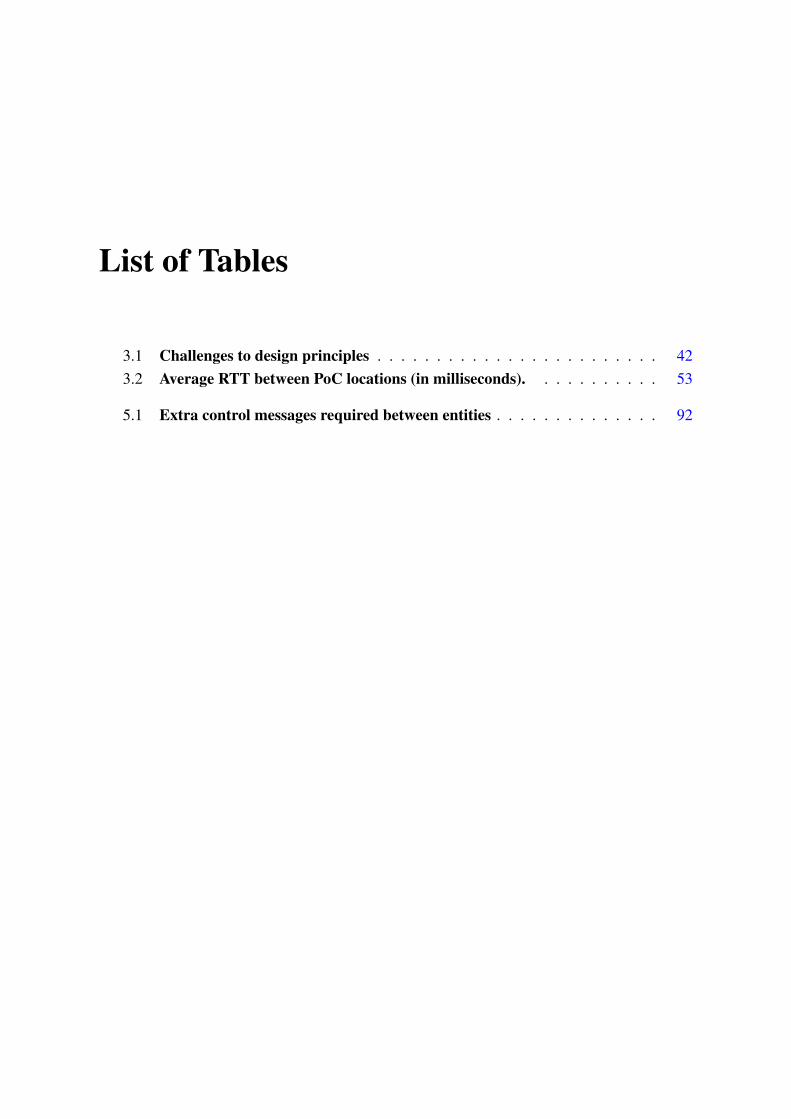
List of Tables
3.1 Challenges to design principles . . . . . . . . . . . . . . . . . . . . . . . . 423.2 Average RTT between PoC locations (in milliseconds). . . . . . . . . . . 53
5.1 Extra control messages required between entities . . . . . . . . . . . . . . 92

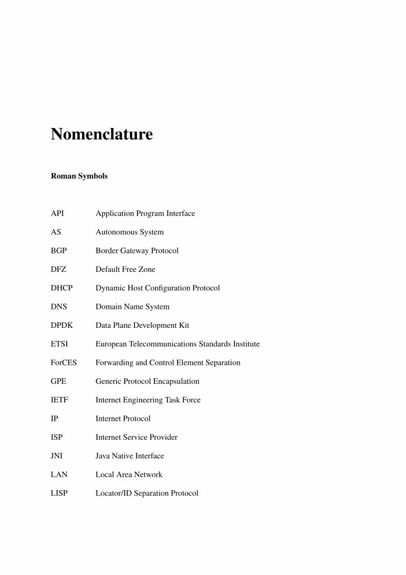
Nomenclature
Roman Symbols
API Application Program Interface
AS Autonomous System
BGP Border Gateway Protocol
DFZ Default Free Zone
DHCP Dynamic Host Configuration Protocol
DNS Domain Name System
DPDK Data Plane Development Kit
ETSI European Telecommunications Standards Institute
ForCES Forwarding and Control Element Separation
GPE Generic Protocol Encapsulation
IETF Internet Engineering Task Force
IP Internet Protocol
ISP Internet Service Provider
JNI Java Native Interface
LAN Local Area Network
LISP Locator/ID Separation Protocol
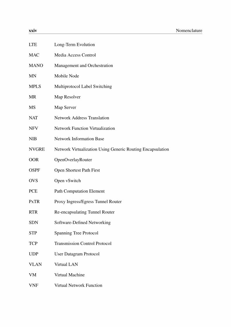
xxiv Nomenclature
LTE Long-Term Evolution
MAC Media Access Control
MANO Management and Orchestration
MN Mobile Node
MPLS Multiprotocol Label Switching
MR Map Resolver
MS Map Server
NAT Network Address Translation
NFV Network Function Virtualization
NIB Network Information Base
NVGRE Network Virtualization Using Generic Routing Encapsulation
OOR OpenOverlayRouter
OSPF Open Shortest Path First
OVS Open vSwitch
PCE Path Computation Element
PxTR Proxy Ingress/Egress Tunnel Router
RTR Re-encapsulating Tunnel Router
SDN Software-Defined Networking
STP Spanning Tree Protocol
TCP Transmission Control Protocol
UDP User Datagram Protocol
VLAN Virtual LAN
VM Virtual Machine
VNF Virtual Network Function
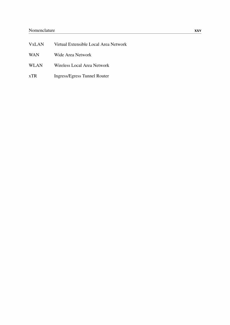
Nomenclature xxv
VxLAN Virtual Extensible Local Area Network
WAN Wide Area Network
WLAN Wireless Local Area Network
xTR Ingress/Egress Tunnel Router

Chapter 1
Introduction
1.1 Background: Legacy networks
Computer networks have become today an element of utter importance. Nowadays, computernetworks are present in almost all the systems that we interact with on daily basis. The rise ofthe Internet over the last decades as a world-wide network publicly accessible to everyone hasshifted the way that people work and interact. However, reaching this point has been an effortof years of research from individuals, companies and institutions.
The development of packet switching networks over the decade of the 60s was the germ tothe computer networks the way we know them today. The need of researchers to interconnectcomputers to enable faster information exchange, long distance communications and no singlepoint of failure made that different efforts evolved in parallel during the 60s and 70s. Thoseefforts, led by different individuals across the world, ended up in designing different methodsand protocols to interconnect computers. Eventually, the different communication proposalsconverged into the family of protocols most widely used today, the TCP/IP stack (TransportControl Protocol / Internet Protocol) [115, 116]. With the advent of TCP/IP as the de factostandard for computer interconnection it was possible for computers from different manufac-tures and software from different developers to exchange information packets using commonprotocols that both sides understand.
However, computer networking not only requires to enable computers to talk with eachother, but also to deploy and manage a networking infrastructure to carry those packets that thecomputers exchange. Computer networks are then composed of packet forwarding elements thatmove the packets from one end point to another. Those forwarding elements comprise severalports and interfaces that link them to other forwarding elements or to end point computers.Packets are clearly labeled with the addresses of the sender and receiver in order to makepossible to deliver them to the correct destination computer. In order to take a path through the
2 Introduction
network that eventually leads to the packet destination, the forwarding elements must knowwhich of their available ports they should forward the packet through. Commonly in computernetworks, the part of a networking device that receives and forwards packets is known as thedata-plane while the part that is in charge of learning and deciding how to forward those packetsreceives the name of control-plane.
In order to find suitable paths to forward the packets, the control-plane at the networkingelements relies on different control protocols. In the effort to offer no single point of failure,these protocols operate decentralized across the different forwarding devices. Control protocolsusually implement distributed algorithms derived from graph theory. For instance, in LocalArea Networks (LAN) leveraging on Ethernet technology [92] it is common to implement theSpanning Tree Protocol (STP) [110] that finds a loop-less tree within the network topology.In large IP-based networks under a single administrative domain the most common approachis to use a link state routing [88] protocol. Link state protocols leverage on the idea that eachforwarding element discovers and announces its neighbors to the rest of forwarding elements.Using variations of the Dijkstra algorithm [17] on that data, each forwarding element is ableto build a map of the network and compute the shortest path per each destination. Notableexamples of link state protocols are Open Shortest Path First (OSPF) [95] and IntermediateSystem to Intermediate System (IS-IS) [9]. Finally, to interconnect IP networks under differentadministrative domains the most widely used protocol is the Border Gateway Protocol (BGP)[120]. In BGP each border router connecting to other administrative domains announces thenetworks reachable through its domain and in exchange it learns the networks reachable throughthe domains of its neighbors.
The described control scheme made the nature of computer networks distributed anddecentralized. At the same time, protocol standardization ensured the correct inter-operation ofdifferent implementations and devices. These two factors combined made possible an organicgrowth of the network without the need for a central authority. For the first time in history, itwas feasible to deploy and manage large computer networks and to interconnect networks ofdifferent administrative domains. Thanks to this decentralization and protocol standardization,computer networks were subject to a rapid spread and expansion. However, in an effort toremain interoperable and backwards compatible with existing deployments, the core networkprotocols (TCP, IP, OSPF, BGP, etc) have seen no fundamental change for the last decades.Although evolutionary enhancements and new protocols have appeared over the years, thefoundations of networking have remained unmodified to the present day. This has come to beknown as network ossification.
Furthermore, the factors that allowed rapid growth and expansion in the early days ofnetworking came with a set of inherent drawbacks. The distributed nature of the protocols
1.2 State-of-the-art: Software-Defined Networking (SDN) 3
require to individually configure each network device. In many cases this has to be donemanually by the network operator. Moreover, this decentralization prevents from havinga global view of the network, which greatly increases the complexity of debugging andoptimization. Although some solutions today enable a partially centralized management, thenetwork itself still operates as a combination of different independent distributed protocols.
Besides, any new protocol to be deployed requires of years of refinement and interoperabilitytesting to ensure compatibility with deployed networks. Even when a new protocol has beenwell-tested and proven to be useful, deploying it in the network is not a trivial task. On one hand,data-plane protocols (such IP) are in most cases implemented in the hardware of forwardingdevices, and thus any new protocol or protocol update involves to individually upgrade theboxes across the network. On the other hand, control protocols, that usually run in softwareand therefore should be easier to upgrade and replace, are still mostly unmodified. The factthat control protocols run in a distributed manner within the networking boxes makes anymodification to them a challenge since many boxes need to be upgraded before the protocolcan be put into use.
Due to network ossification, all the described challenges are still present in current networkstoday. For a long time, researchers have been looking into ways of dealing with the ossificationof the network and of facing the inherent problems of the current networking paradigm.Nevertheless, in the later years it has arose a solution that has gained major traction and interestfrom both academia and the industry, Software-Defined Networking (SDN).
1.2 State-of-the-art: Software-Defined Networking (SDN)
Software-Defined Networking (SDN) arose as a solution to deal with the limitations of tradi-tional networking. Although there are different definitions for SDN depending on the focusand scope [48], [35], [61], it is generally agreed that a SDN solution comprises two maincharacteristics. The decoupling of data and control planes and the centralization of networkcontrol. This is possible through the use of well-defined interfaces between the control-planeand data-plane elements, which in turn enables remote network programability.
In SDN networks, the control-plane is extracted from the data-plane devices and pushed toa new network element, the SDN controller. This controller centralizes the network control in asingle logical point and via a southbound interface it remotely programs the forwarding rules atthe data-plane devices. The decoupling that SDN introduces allows data and control planes toevolve independently. Data-plane research can focus on improving the forwarding performanceand on ways to better expose the forwarding internals to the controller while the control logic isimplemented as software running on the controller. The control software instructs the controller
4 Introduction
on how it should program the data-plane and decides what to do when the data-plane receivesnew or unexpected traffic.
1.2.1 OpenFlow Protocol
The research community generally agrees on idea that the current SDN trend started with theOpenFlow [87] protocol developed at the Stanford university. According to Feamster et al. [35]the term Software-Defined Networking was first coined in a MIT (Massachusetts Institute ofTechnology) press article [45] about OpenFlow where the author stated:
Frustrated by this inability to fiddle with Internet routing in the real world, Stanfordcomputer scientist Nick McKeown and colleagues developed a standard calledOpenFlow that essentially opens up the Internet to researchers, allowing them todefine data flows using software - a sort of "software-defined networking".
However, the ideas of decoupling control from data or centralizing the network control werenot first mentioned with the OpenFlow protocol. On one hand, the trend on active networking[135] was already discussing network programmability in the decade of 1990. On the otherhand, proposals like Path Computation Element (PCE) [34] or Forwarding and Control ElementSeparation (ForCES) [20] respectively offered centralized control or decoupled data and controlplanes in the 2000s. Moreover, the work on the Click modular router [68] in 2000 explored thepotential of flexible, modular and highly configurable data-plane devices. Current SDN is theresult of a long history of research from different authors. The OpenFlow specification itselfbuilds on top of ideas from just prior works like 4D [44] and Ethane [12]. For a summary ofthe research history that led to SDN we recommend the work of Feamster et al. in [35].
Despite some misconceptions on the topic, SDN as commonly understand today is notconstrained to the OpenFlow protocol. Although OpenFlow is probably the most notoriousexample of a SDN southbound protocol, it is not the only one. The definition and scopeof SDN varies across the research community and in that sense, industry and academia areexperimenting with different SDN protocols. Depending on the use-case and scenario otherprotocols can be deployed, sometimes in parallel with OpenFlow. At the time of this writing,and without trying to be exhaustive, other notable examples of protocols used for SDN are: theForwarding and Control Element Separation (ForCES) Protocol [20], the Path ComputationElement (PCE) Communication Protocol (PCEP) [139], Locator/ID Separation Protocol (LISP)[30], the Border Gateway Protocol (BGP) [120] and the Network Configuration Protocol(NETCONF) [24]. It is worth to note that some of the protocols used today for SDN weredeveloped prior to OpenFlow appearance and even before the term SDN was coined.
1.2 State-of-the-art: Software-Defined Networking (SDN) 5
For reference and due to its importance in the evolution of SDN, in what follows we discussbriefly the OpenFlow architecture. In its very basic form [87, 52], an OpenFlow switch hasa flow table and an OpenFlow channel towards the SDN controller. Flow tables contain flowrules, each of them is composed by a set of matching fields (e.g. destination IP address, VLANtag, etc) and the actions to perform in the packet (e.g. modify source Ethernet address, forwardpacket through a specific port, etc). When an incoming packet is received, it is matched againstthe flow table and the appropriate actions are taken. If no suitable rule is found (i.e. the packetmatches no rule), the switch has to ask the controller what to do with the packet. It does soby means of the packet_in OpenFlow message which sends the packet to the controller. Thecontroller can then insert a new rule in the flow table (or modify an existing one) using theflow_mod message. In many cases, the controller has proactively programmed the OpenFlowswitch using flow_mod messages rather than waiting for packet_in messages to happen.
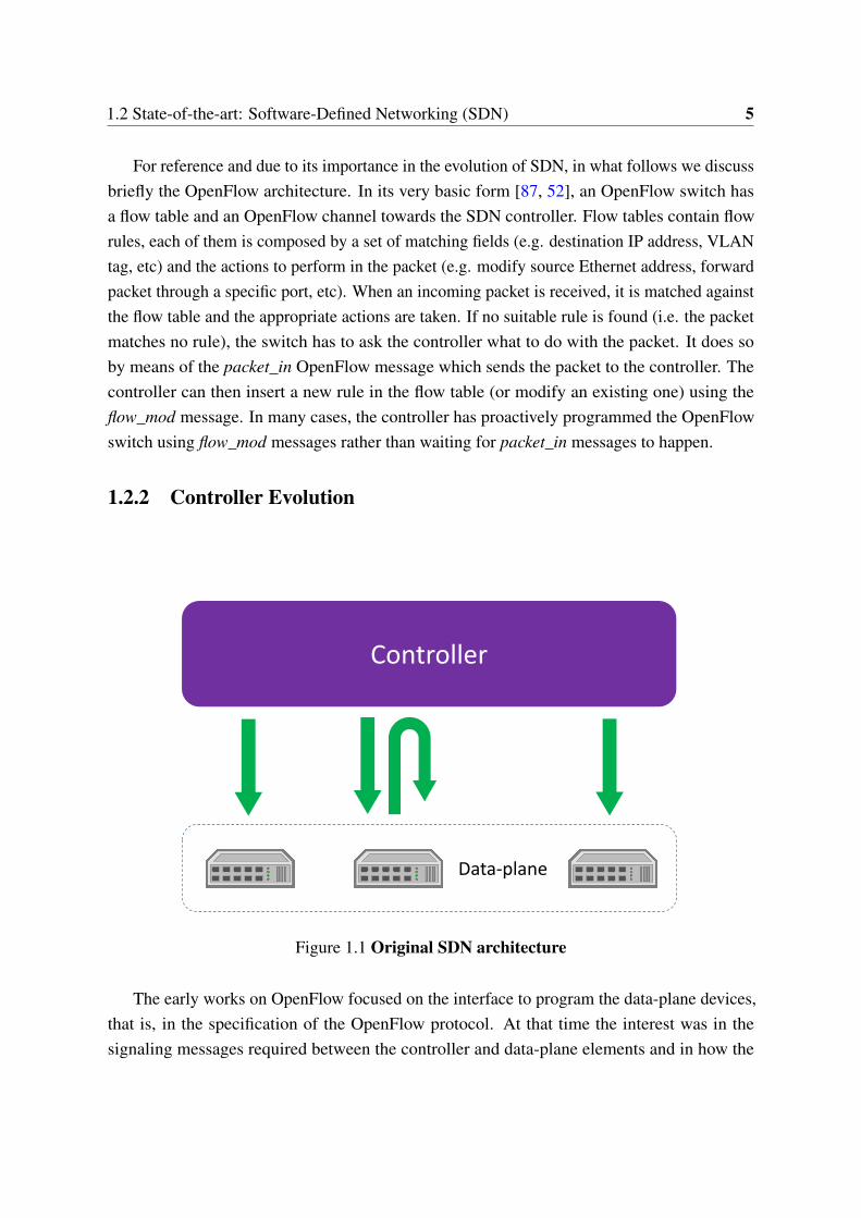
1.2.2 Controller Evolution
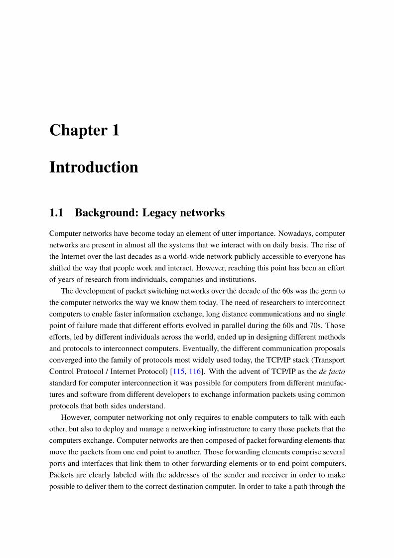
Controller
Data-plane
Figure 1.1 Original SDN architecture
The early works on OpenFlow focused on the interface to program the data-plane devices,that is, in the specification of the OpenFlow protocol. At that time the interest was in thesignaling messages required between the controller and data-plane elements and in how the
6 Introduction
former should expose their internal forwarding tables. The first conceptual ideas of SDN, asimagined by the original OpenFlow article [87], devised a SDN architecture as the one depictedin Fig. 1.1. In those early architectures there was non distinction between the controller and theactual software pieces that implemented the control logic. Control applications where part ofthe controller itself.
Building on top of the OpenFlow architecture, the research community started to exploreand refine the SDN controller. One of the first controller designs to appear was NOX [47], whichpresented the controller as an operating system for networks. NOX introduced the idea of thecontroller as a mere programmatic interface to the network where the applications implementedon top were the ones in charge of the actual network control. Today, the interface that thecontroller exposes to the software control applications is usually referred as the northboundinterface. The authors of NOX proposed one of the first northbound SDN interfaces, theFlow-based Management Language [54]. That interface was still rather simple (and stronglyinfluenced by the OpenFlow protocol) but provided enough abstraction to enable developing ofapplications on top. NOX also introduced another key concept on modern SDN, a databasestoring the global view of the network. NOX used this database to store observations madefrom the network, such the topology of switches, the location of hosts and middleboxes, theservices offered in the system, etc. Via the controller, the northbound control applications usedthe state stored in the database to make control decisions.
As the interest and research on SDN continued over the years, it was clear that this newparadigm opened new possibilities for networking but also brought new challenges. Thecentralization of the control allows to keep a global view of the network and act on the networkas a whole, but at the same time requires of carefully design to keep the controller scalable.In that sense, both the academia and the industry have discussed different implementationapproaches to scale the SDN controller. Most of them comprise a distributed controller thatis logically centralized but supported by different physical nodes. Such controllers use adistributed database to store the global network state. One of the first and most well-knownproposals of a distributed controller is Onix [71].
Onix addresses the scalability requirements of the controller by enforcing a strongly dis-tributed approach. Onix is composed of different controller instances running across differentservers. These servers also store partitions of a distributed database where Onix stores thenetwork state. A major contribution of Onix to the SDN field is the introduction of the termNetwork Information Base (NIB). The NIB refers to the network state stored at the databasethat provides detailed information on the network. Compared to NOX, Onix also improvesthe northbound interface offering a more general API to northbound applications. Onix hasinspired important following research on distributed controllers such B4 [59] and ONOS [5]. B4
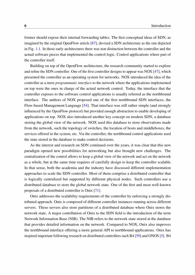
1.2 State-of-the-art: Software-Defined Networking (SDN) 7
Data-plane
Controller State
App App
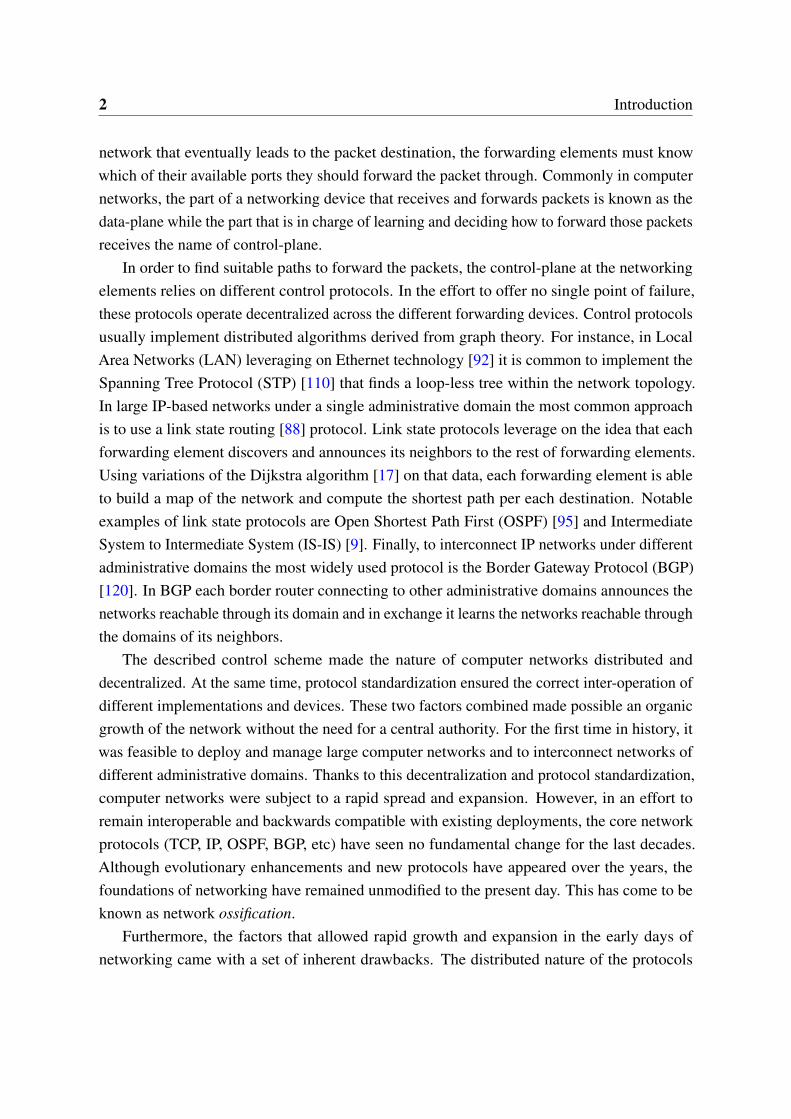
Figure 1.2 State-of-the-art SDN architecture
proposes a decentralized controller to control a large worldwide WAN network. Building on thesteps of Onix and B4, ONOS (Open Network Operating System) represents the state-of-the-arton distributed SDN controllers. ONOS offers an optimized architecture that leverages on thelatest advancements on distributed systems and distributed databases to offer high performance,low latency and great scale-out capabilities.
Besides ONOS, the OpenDaylight [89] controller represents an excellent example of amodern controller, cluster-oriented and with support for several different northbound and south-bound protocols. The general architecture of modern controllers (such ONOS or OpenDaylight)is depicted in Fig. 1.2. As the figure suggests, network applications running on top generatecontrol policies through the northbound interface. These policies are usually expressed bymeans of an intent-driven language (e.g. declarative) that has to be latter processed by thecontroller. Examples of such declarative northbound interfaces can be found in [36, 66, 93].The controller renders these abstract directives into specific data-plane rules making use of thenetwork state that is stored in the state database. The data-plane specific state is then pushedto the data-plane devices via a southbound protocol. Despite the reactive (e.g. pull-based)early works on SDN [12, 47], most of the controller designs today heavily rely on proactivelypushing the state to the data-plane elements in advance.
8 Introduction
In general, the current state-of-the-art shows how the controllers are designed to cope withthe scalability requirements of modern SDN deployments. However, achieving the requiredscalability imposes several distribution tradeoffs that controllers need to balance and that arewell-documented in the research literature [76, 53, 112, 10, 131, 130, 19, 5, 71]. This makes thedesign of SDN controllers a non-trivial and complex endeavor. Moreover, the design complexityis expected to rise as SDN moves to new scenarios and has to face additional challenges. Inthis thesis we wonder if it is possible to follow a different approach when designing SDNcontrollers.
1.3 Motivation: Decoupling State from Control
Interestingly, all current SDN approaches keep the network state architecturally as part of thecontroller. The network state, network information base or global network view (dependingon the controller terminology) is always kept within the logical boundaries of the controller.In terms of deployment this does not constrain the back-end database storing the state to bephysically allocated within the same machines that host the controller instances, although thisis a common scenario. In existing SDN proposals, the state is not directly exposed to thenorthbound applications or the southbound data-plane devices, rather southbound events ornorthbound updates go through the controller, which is then in charge of modifying the state.
However, there are scenarios with characteristics that would advise to use a design that takesthe state logically out of the controller. This thesis arguments that the network state can be aSDN component on its own, in the same terms than the controller, the northbound applicationsor the data-plane devices. In the same way that SDN originally decoupled control from data,this thesis lays the foundations to explore the decoupling of state from control. It should benoted that this thesis does not propose to create the entity of the network state. Such entity isalready well-defined (under different names) on SDN literature. Similarly to the dissociation ofcontroller and control applications, that led to the definition of the northbound interface, thisthesis does not introduce the state, but rather defines it as a different entity dissociated from thecontroller.
This logical separation entitles state and controller to scale independently. This allows tofocus on their different individual requirements, since the set of skills required to design ascalable controller are different from those needed to design a scalable state database. Movingthe state to a disjoint database moves along many of the scalability requirements of the controllerto this database. Therefore, the scalability of the SDN system is no longer tied to the scalabilityof the controller but rather to the scalability of the state database. To scale the database thereis no need to reinvent the wheel and instead all the research and advancements on the field of
1.4 Objectives: Decoupled-State Architectures 9
-distributed- databases can be directly leveraged. Furthermore, state decoupling removes orminimizes the requirement for an east-west interface across different controller instances. Therequirement of inter-controller communication was mostly due to the need to distribute andcoordinate the state across instances. However, when the state is moved to an external entity, thedistribution task is handed to the back-end database and thus the coordination among controllerinstances alleviated. In general, the state-decoupling eases the design of SDN architectures andparticularly of those that require of special interaction with the network state.
1.4 Objectives: Decoupled-State Architectures
Trying to put the state-control decoupling into context, this work describes particular SDNscenarios where a decoupling of state and control would be more effective than keeping thestate within controller boundaries. Furthermore, it describes SDN architectures, designed forthose scenarios, that take advantage of state-control decoupling. This work identifies twocases where a decoupled-state approached would be beneficial, when the control has to beasynchronous and when the control has to be decentralized.
1.4.1 Asynchronous Control
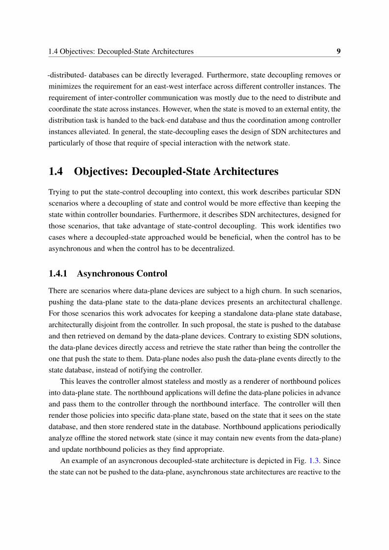
There are scenarios where data-plane devices are subject to a high churn. In such scenarios,pushing the data-plane state to the data-plane devices presents an architectural challenge.For those scenarios this work advocates for keeping a standalone data-plane state database,architecturally disjoint from the controller. In such proposal, the state is pushed to the databaseand then retrieved on demand by the data-plane devices. Contrary to existing SDN solutions,the data-plane devices directly access and retrieve the state rather than being the controller theone that push the state to them. Data-plane nodes also push the data-plane events directly to thestate database, instead of notifying the controller.
This leaves the controller almost stateless and mostly as a renderer of northbound policesinto data-plane state. The northbound applications will define the data-plane policies in advanceand pass them to the controller through the northbound interface. The controller will thenrender those policies into specific data-plane state, based on the state that it sees on the statedatabase, and then store rendered state in the database. Northbound applications periodicallyanalyze offline the stored network state (since it may contain new events from the data-plane)and update northbound policies as they find appropriate.
An example of an asyncronous decoupled-state architecture is depicted in Fig. 1.3. Sincethe state can not be pushed to the data-plane, asynchronous state architectures are reactive to the
10 Introduction
Controller
Data-plane
State
App App
Figure 1.3 Asynchronous SDN architecture
data-plane traffic. Similarly to Ethane [12] and NOX architectures [47], they also rely on thefirst packet of each flow to trigger the retrieval of state from the controller. A decoupled-statearchitecture for asynchronous communication will greatly rely on that mechanism and thusrequire state exchange protocols optimized for a pull-based model.
OpenFlow allows to ask the controller for the rules to handle a particular flow or sendpackets to the controller for inspection via the packet_in message. The main motivation forsuch mechanism was to cover the cases where the data-plane lacks the rules to process certainincoming traffic. In that sense, OpenFlow is a candidate to be used to reactively program thedata-plane devices as response to the observed data-plane traffic. Other option that we analyzein this thesis is to use the LISP protocol since it was specifically designed to quickly retrieveand exchange operational state via pull-based mechanisms.
Furthermore, the scenarios where the control communication with the data-plane has tobe asynchronous may not benefit from a protocol that requires maintaining a connectionestablished with the controller. Data-plane devices will likely be mobile or transient whichwill lead to frequent connection reestablishment. In our work we leverage on LISP since it is
1.4 Objectives: Decoupled-State Architectures 11
already connectionless, but another option is to use connection-oriented protocols that onlyestablished short lived connections, such gRPC [46].
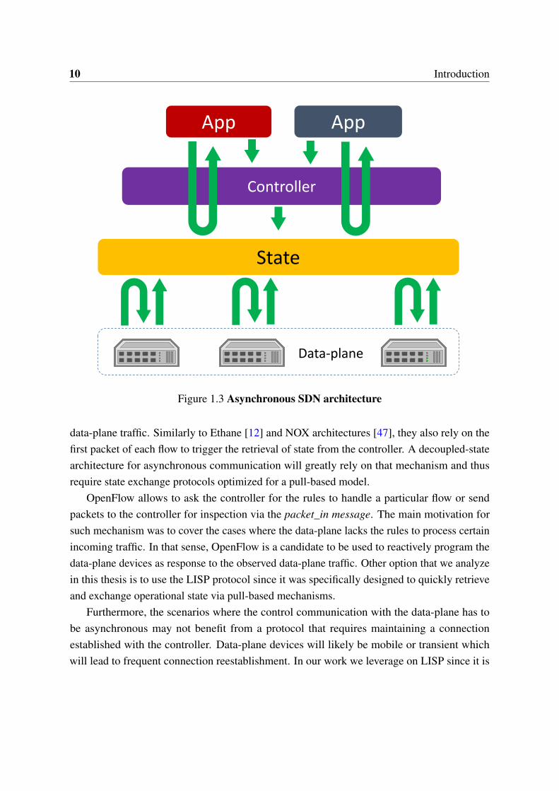
1.4.2 Decentralized Control
In general, it is agreed that the control centralization brought by SDN enables many benefits,but also comprises several drawbacks. On one hand, keeping the centralized controller scalableis an architectural challenge. Besides, there is an inherent latency burden imposed due to theinter-controller signaling involved. Part of the research community is starting to wonder ifthe required distribution of the controller would not bring the same problems that the originaldistribution of network control brought. Although this is arguable, it raises a valid concern. Atthe time of this writing it is still too early to evaluate the long time consequences of distributedcontrollers.
On the other hand, the centralized design aggregates and combines local information whichmay conceal local details. Current centralized approaches may result infeasible in scenariosthat require fine grain control of local traffic while remaining performance efficient and scalable.For instance, we believe that Network Function Virtualization (NFV) may be one of thosescenarios. Some NFV use-cases may need a fine local control of the traffic while still beingglobally orchestrated. NFV is a rising trend in the industry and examples of it are the ETSINFV framework [27] or the ETSI-hosted Open Source MANO (OSM) [101] project.
To cope with the decentralization concerns and to allow fine-grain local control in thescenarios that require it, this thesis describes the idea of a decentralized SDN architecture withcentralized state. A decoupled-state architecture that keeps the state centralized but pushes thecontrollers close to the data-plane devices they control, as depicted in Fig. 1.4. In contrast toexisting SDN, the control is distributed over the network, but federated and coordinated thanksto the shared state database. Such architecture seeks to find a balance among the traditionaldecentralized networks and the new centralized approaches brought by SDN. Despite thedecentralization of the control, it is easier to manage decentralized decoupled-state networkswhen compared to classical decentralized networks since it is still possible to obtain a globalview of the network from the centralized state.
In decentralized decoupled-state architectures, the global state is partially cached locally atthe controllers. This makes a difference with the case of asynchronous decoupled-state archi-tectures, since the controllers of the decentralized architectures are not stateless. Furthermore,to control their local data-plane devices decentralize controllers also generate local state that isonly used locally by the local controller and not pushed to the global state database.
In the context of SDN, it should be noted that a decentralized control is not the same asa distributed control. While most SDN proposals today comprise distributed control to cope
12 Introduction
Controller
Data-plane
State
App
App
Controller
App
App
Controller
App
App
Figure 1.4 Decentralized SDN architecture
with scalability requirements [130, 19, 11], the controller is still a single logical entity. In thedecentralized approach described in this thesis each controller is standalone and independentfrom the others. In distributed architectures the different controllers coordinate among themthrough the so called east-west interface. Via east-west communication, the different instancesare tied together into a single logical controller. Contrary, the decentralized controllers donot exchange messages among themselves (i.e. there is no east-west interface), they only-indirectly- coordinate through the global state that they share.
1.5 Methodology: Research-Standardize-Implement
First the idea of decoupling state from control and then the development of decoupled-statearchitectures, are both the result of an iterative process that involved research, standardizationand implementation. In this section we briefly describe the iterative methodology that has beenapplied in this thesis, which we also summarize in Fig. 1.5.
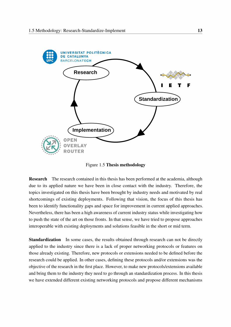
1.5 Methodology: Research-Standardize-Implement 13
Research
Standardization
Implementation
Figure 1.5 Thesis methodology
Research The research contained in this thesis has been performed at the academia, althoughdue to its applied nature we have been in close contact with the industry. Therefore, thetopics investigated on this thesis have been brought by industry needs and motivated by realshortcomings of existing deployments. Following that vision, the focus of this thesis hasbeen to identify functionality gaps and space for improvement in current applied approaches.Nevertheless, there has been a high awareness of current industry status while investigating howto push the state of the art on those fronts. In that sense, we have tried to propose approachesinteroperable with existing deployments and solutions feasible in the short or mid term.
Standardization In some cases, the results obtained through research can not be directlyapplied to the industry since there is a lack of proper networking protocols or features onthose already existing. Therefore, new protocols or extensions needed to be defined before theresearch could be applied. In other cases, defining these protocols and/or extensions was theobjective of the research in the first place. However, to make new protocols/extensions availableand bring them to the industry they need to go through an standardization process. In this thesiswe have extended different existing networking protocols and propose different mechanisms
14 Introduction
to enable new features in existing solutions. This standardization process has been mostlycarried out at the Internet Engineering Task Force (IETF), the major venue for standardizationof Internet related protocols. The standardization process entitled us to bring our tentative ideasto the community at large and receive feedback from networking experts. This allowed us torefine our designs and ensure that our proposals were feasible and interoperable with existingsolutions.
Implementation Once required protocols or extensions are available as a result of the stan-dardization process, it is possible to actually implement the solutions defined in the researchphase. In this thesis we strongly leverage on validating our research via real implementationrather than using simulation or analytical tools. The architectures and discussions presented inthis thesis are supported by solid prototyping and actual deployments. For that we have madea strong use of the OpenOverlayRouter (OOR) project [100]. OOR is a project maintainedby our research group that enables to deploy programmable overlay networks and offers aflexible platform for rapid development and easy prototyping. During the span of this thesisseveral features arose as a result of the research conducted and were added to OOR. Besidesour in-house OOR project, we have also leveraged on the OpenDaylight controller [103] towhich we have also contributed. Finally, it should be noted the conclusions gather from theimplementation and prototyping experience leaded to rethink the proposals conceived duringthe research phase or opened the path for new research topics.
1.6 Outline and Contributions of this Thesis
To summarize the scope and contributions of this thesis, in this section we briefly describe theoutline of this document, the contents of each part and the contributions associated to eachchapter.
1.6.1 Introduction
To put this work into context, we have given an historical overview of legacy networking andhow it leaded to the need for SDN. After that we have summarized the origin and evolutionof SDN and the different designs for SDN controllers over the years. From this analysis onthe state-of-the-art on SDN we concluded that current controller approaches do not suffice tofulfill the requirements of certain scenarios. In that sense, we introduced the idea that it maybe beneficial to explore taking the state out of the SDN controller. The concept of decouplingstate and control in SDN is the motivation of this thesis and its main contribution.
1.6 Outline and Contributions of this Thesis 15
1.6.2 Part I: Decoupled-State Architectures
In Part I, we introduce two different types of decoupled-state SDN architectures (asynchronousand decentralized) and propose instances of both types designed for specific use-cases. Interest-ingly, the different solutions that we propose leverage on the Locator/ID Separation Protocol(LISP) [30] as the protocol for state exchange. Therefore prior to delve into the details of thearchitectures we analyze LISP as a protocol for SDN.
In Chapter 2 we describe the use of LISP as an SDN protocol and analyze LISP architectureand components from the point of view of SDN. This leads to highlight the particularitiesof LISP and to present the benefits and drawbacks of using LISP for SDN. Furthermore, webuild a prototype to validate the analysis and to show the feasibility of an SDN solution basedon LISP. After analyzing LISP we present two different LISP-based decoupled-state SDNproposals and the scenarios that motivate them.
On one hand, asynchronous decoupled-state architectures are suitable when data-planedevices are subject to a high churn. This is the case for end-nodes, such smartphones andhome-routers, since they are transient and/or highly mobile. Following this idea, Chapter 3proposes a SDN architecture specifically designed for end-nodes. The architecture leverages ondistributed and symmetric controller nodes that offer an intent-driven northbound to the controlapplications and on a state database provisioned with a connectionless pull-based southboundtowards the data-plane nodes.
On the other hand, this work highlights the case of Network Function Virtualization (NFV)for operator networks as one case where the SDN centralization may be impractical. NFV foroperators can benefit from a decoupled-state architecture that decentralizes the control andachieves better local processing. For this scenario Chapter 4 describes an architecture wherethe state remains centralized, but the controllers are pushed close to the data-plane devices.
Contributions of Part I
• Chapter 2 - LISP as a Protocol for State Exchange in SDN
– Paper: Rodriguez-Natal, Alberto, Marc Portoles-Comeras, Vina Ermagan, DarrelLewis, Dino Farinacci, Fabio Maino, and Albert Cabellos-Aparicio. "LISP: asouthbound SDN protocol?" Communications Magazine, IEEE 53.7 (2015): 201-207.
– Code: Original LISP northbound interface for the OpenDaylight SDN controller.https://github.com/opendaylight/lispflowmapping
– Internet-Draft Ermagan, Vina, Alberto Rodriguez-Natal, Florin Coras, AlbertCabellos-Aparicio, and Fabio Maino. "LISP Configuration YANG Model", draft-
16 Introduction
ietf-lisp-yang-01, December 2015, (work in progress).https://tools.ietf.org/html/draft-ietf-lisp-yang-01
– Internet-Draft Rodriguez-Natal, Alberto, Albert Cabellos-Aparicio, Vina Erma-gan, Fabio Maino, and Sharon Barkai. "MS-originated SMRs", draft-rodrigueznatal-lisp-ms-smr-01, April 2016, (work in progress).https://tools.ietf.org/html/draft-rodrigueznatal-lisp-ms-smr-01
– Internet-Draft Rodriguez-Natal, Alberto, Albert Cabellos-Aparicio, Sharon Barkai,Vina Ermagan, Darrel Lewis, Fabio Maino, and Dino Farinacci. "LISP support forMulti-Tuple EIDs", draft-rodrigueznatal-lisp-multi-tuple-eids-01, January 2016,(work in progress).https://tools.ietf.org/html/draft-rodrigueznatal-lisp-multi-tuple-eids-01
• Chapter 3 - Asynchronous SDN Architecture for End-Nodes
– Paper: Rodriguez-Natal, Alberto, Vina Ermagan, Kien Nguyen, Sharon Barkai,Yusheng Ji, Fabio Maino, and Albert Cabellos-Aparicio. “SDN for End-Nodes.”(under review).
• Chapter 4 - Decentralized SDN Architecture for Operators NFV
– Paper: Rodriguez-Natal, Alberto, Vina Ermagan, Ariel Noy, Ajay Sahai, GidiKaempfer, Sharon Barkai, Fabio Maino, and Albert Cabellos-Aparicio. “Globalstate, local decisions: Decentralized NFV for ISPs via enhanced SDN.” (underreview).
– Internet-Draft: Barkai, Sharon, Dino Farinacci, David Meyer, Fabio Maino, VinaErmagan, Alberto Rodriguez-Natal, and Albert Cabellos-Aparicio. "LISP BasedFlowMapping for Scaling NFV", draft-barkai-lisp-nfv-07, December 2015, (workin progress).https://tools.ietf.org/html/draft-barkai-lisp-nfv-07
1.6.3 Part II: Deploying SDN for End-Nodes
This thesis identifies SDN for end-nodes as an open-field for study and research. As it has beenalready mentioned, in Chapter 3 we explore an asynchronous architecture for end-nodes thatrelies on the LISP protocol for state exchange. In Part II we go deeper into the implications ofmaking SDN available for end-nodes, and particularly of doing so via LISP. In that sense, inChapter 5 we analyze the particularities of LISP when applied to mobility scenarios. Particularly,we discuss location and identity privacy issues of the LISP protocol when used for mobile-nodes.

1.6 Outline and Contributions of this Thesis 17
Furthermore, in Chapter 6 we describe and benchmark OpenOverlayRouter, an open-sourceoverlay software that implements LISP to enable SDN at end-nodes.
Contributions of Part II
• Chapter 5 - Privacy for LISP Mobile Nodes
– Paper: Rodriguez-Natal, Alberto, Lorand Jakab, Marc Portoles-Comeras, VinaErmagan, Preethi Natarajan, Fabio Maino, and Albert Cabellos-Aparicio. "LISP-MN: mobile networking through LISP." Wireless personal communications 70.1(2013): 253-266.
– Paper: Rodriguez-Natal, Alberto, Lorand Jakab, Vina Ermagan, Preethi Natarajan,Fabio Maino, and Albert Cabellos-Aparicio. "Location and identity privacy forLISP-MN." International Conference on Communications (ICC), IEEE, 2015.
• Chapter 6 - OpenOverlayRouter: Architecture and Evaluation
– Paper: Rodriguez-Natal, Alberto, Florin Coras, Albert Lopez-Bresco, LorandJakab, Marc Portoles-Comeras, Preethi Natarajan, Vina Ermagan, David Meyer,Dino Farinacci, Fabio Maino, and Albert Cabellos-Aparicio. “OpenOverlayRouter:Architecture and Performance.” (under review).
– Code: Developer and maintainer for the OpenOverlayRouter project (formerlyLISPmob), an open-source implementation to deploy programmable overlays.http://www.openoverlayrouter.org/
1.6.4 Thesis Summary and Open Research
Finally, this work explores the implications and future work regarding decoupled-state SDNarchitectures in Chapter 7. Particularly, we expose that the interfaces to interact with adecoupled-state require further investigation and that an standalone state database requires ofcareful analysis.

Part I
Decoupled State Architectures

Chapter 2
LISP as a Protocol for State Exchange inSDN
This chapter describes how the Locator/ID Separation Protocol (LISP) can be used as a protocolfor SDN. LISP basic idea is to split current IP addresses overlapping semantics of identity andlocation in two separate namespaces. Since its inception the protocol has gained considerableattention from both the industry and the academia motivating several new use cases to beproposed. Despite its inherent control-data decoupling and the abstraction and flexibility itintroduces into the network, little has been said about the role of LISP on the SDN paradigm.LISP is specially interesting as an SDN protocol since it can fit as a state exchange protocolfor decoupled-state architectures. In this chapter we try to fill the gap and present a systematicanalysis of the relevant SDN requirements and how such requirements can be fulfilled bythe LISP architecture and components. This results in a set of benefits (e.g., incrementaldeployment, scalability, flexibility, interoperability and inter-domain support) and drawbacks(e.g., extra headers and some initial delay) of using LISP for SDN. In order to validate theanalysis, we have built and tested a prototype using the OpenOverlayRouter open-sourceimplementation of LISP. Finally, it should be noted that although Chapter 3 and Chapter 4 showthe benefits of using LISP for decoupled-state SDN architectures, this chapter present LISP asa general southbound protocol for SDN, and thus not constrains its usage for decoupled-statearchitectures only.
2.1 Introduction
The LISP [30] decouples identity from location on IP addresses by creating two separatenamespaces, EIDs (Endpoint Identifiers) to identify hosts and RLOCs (Routing Locators) to
22 LISP as a Protocol for State Exchange in SDN
route packets over transit networks. LISP follows a map-and-encap approach to map identifiersto locators and encapsulate EID traffic into RLOC packets. EID packets are intercepted byborder routers and encapsulated towards the RLOC of the router serving the destination EIDdomain. On the other hand, the LISP control-plane uses a publicly accessible distributeddatabase -known as Mapping System- to register and request EID-to-RLOC mappings. Withthis LISP effectively decouples control and data planes and creates a dynamic EID-basedoverlay network on top of an RLOC-based underlay, that can be programmed by simplyinteracting with the Mapping System.
LISP original purpose was to solve the scalability issues of the Internet Default-free Zone(DFZ) routing tables by pushing traffic engineering practices to the identifiers space whilekeeping the locators space quasi-static and highly aggregatable. At the time of this writing LISPhas been deployed in a pilot network [80] that includes more than 20 countries and hundredsof institutions. LISP hardware and software are also widely available, both in open-source[100, 104] and proprietary implementations [81].
As a result of the LISP standardization and research efforts, the protocol has grown architec-turally and has been applied to use cases beyond its original purpose. Since its inception, LISPhas gained a significant traction on both the industry and the academia due to the possibilitiesof its programmable overlays [129]. LISP-enabled dynamic overlays provide a standardized,inter-domain, and programmable framework to enable low-CAPEX innovation at the networklayer. Therefore, there is a growing interest on the role of LISP in Software-Defined Network-ing (SDN) and on how SDN can benefit from LISP overlays. Interestingly, LISP is alreadybecoming part of SDN solutions such the OpenDaylight controller [103]. In this chapter weanalyze the relation between the LISP architecture and the SDN paradigm.
As described in Chapter 1, there are two well-defined parts in any SDN deployment: thenorthbound and the southbound interfaces. The northbound offers a high level applicationprogramming interface, where control applications can be deployed. The southbound is a lowlevel interface used to operate with the raw network elements. Currently, there is ongoing effortin defining the high level abstraction interface (see Frenetic [36] or Procera [66] as examples).With respect to the southbound interface there are as well several options, being OpenFlow[87] the one that has gained major widespread on the industry.
One of the contribution of this thesis is to analyze LISP as a southbound SDN protocol. Forthis, this chapter presents a systematic analysis of the fundamental SDN requirements -inferredfrom the literature [61, 36, 66, 87, 131, 76, 144, 13, 71]- and how such requirements can befulfilled by the LISP architecture and components.
The analysis results in a set of qualitative advantages and drawbacks as well as recom-mended potential improvements to overcome the identified issues. In order to validate the
2.2 Background: Locator/ID Separation Protocol (LISP) 23
analysis, we build and test a prototype using the OpenOverlayRouter (formerly LISPmob)open-source implementation.
2.2 Background: Locator/ID Separation Protocol (LISP)
Current IP addresses convey the semantics of both identity and location, which has beenconsidered an issue since the early days of networking [133]. Trying to alleviate this semanticoverload LISP decouples host identity from its location by creating two different namespaces:Endpoint Identifiers (EIDs) and Routing Locators (RLOCs). Hosts are identified by an EID,and topological network locations by RLOCs. To keep LISP incrementally deployable, in itsvery basic form EIDs and RLOCs are syntactically identical to current IPv4 and IPv6 addresses.However, the protocol allows arbitrary address families (e.g. MAC addresses) to be used.
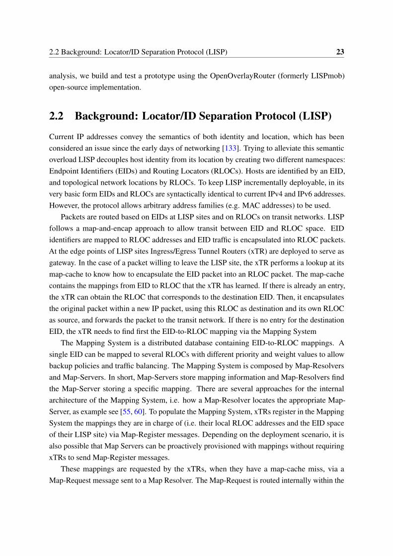
Packets are routed based on EIDs at LISP sites and on RLOCs on transit networks. LISPfollows a map-and-encap approach to allow transit between EID and RLOC space. EIDidentifiers are mapped to RLOC addresses and EID traffic is encapsulated into RLOC packets.At the edge points of LISP sites Ingress/Egress Tunnel Routers (xTR) are deployed to serve asgateway. In the case of a packet willing to leave the LISP site, the xTR performs a lookup at itsmap-cache to know how to encapsulate the EID packet into an RLOC packet. The map-cachecontains the mappings from EID to RLOC that the xTR has learned. If there is already an entry,the xTR can obtain the RLOC that corresponds to the destination EID. Then, it encapsulatesthe original packet within a new IP packet, using this RLOC as destination and its own RLOCas source, and forwards the packet to the transit network. If there is no entry for the destinationEID, the xTR needs to find first the EID-to-RLOC mapping via the Mapping System
The Mapping System is a distributed database containing EID-to-RLOC mappings. Asingle EID can be mapped to several RLOCs with different priority and weight values to allowbackup policies and traffic balancing. The Mapping System is composed by Map-Resolversand Map-Servers. In short, Map-Servers store mapping information and Map-Resolvers findthe Map-Server storing a specific mapping. There are several approaches for the internalarchitecture of the Mapping System, i.e. how a Map-Resolver locates the appropriate Map-Server, as example see [55, 60]. To populate the Mapping System, xTRs register in the MappingSystem the mappings they are in charge of (i.e. their local RLOC addresses and the EID spaceof their LISP site) via Map-Register messages. Depending on the deployment scenario, it isalso possible that Map Servers can be proactively provisioned with mappings without requiringxTRs to send Map-Register messages.
These mappings are requested by the xTRs, when they have a map-cache miss, via aMap-Request message sent to a Map Resolver. The Map-Request is routed internally within the
24 LISP as a Protocol for State Exchange in SDN
Host A Tunnel Router X Host B
Mapping System
EID space EID spaceRLOC space
Tunnel Router Y
XA
YBControl
Data
Identifier
Locator
Encap. Data
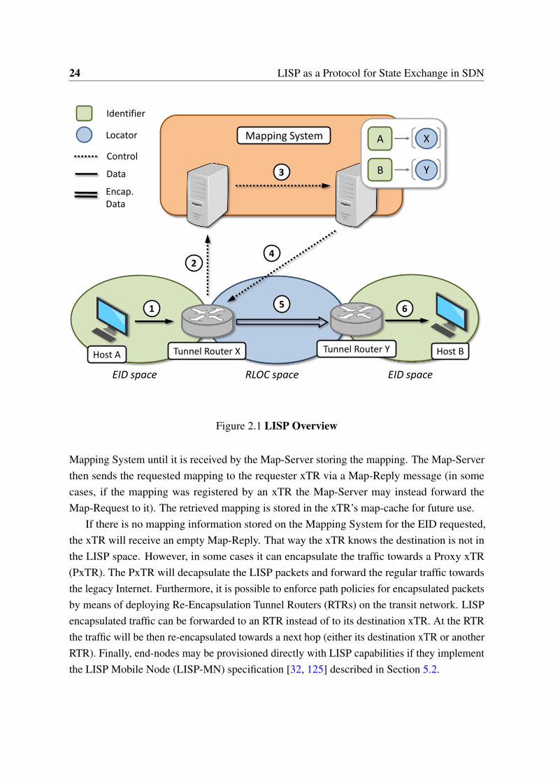
Figure 2.1 LISP Overview
Mapping System until it is received by the Map-Server storing the mapping. The Map-Serverthen sends the requested mapping to the requester xTR via a Map-Reply message (in somecases, if the mapping was registered by an xTR the Map-Server may instead forward theMap-Request to it). The retrieved mapping is stored in the xTR’s map-cache for future use.
If there is no mapping information stored on the Mapping System for the EID requested,the xTR will receive an empty Map-Reply. That way the xTR knows the destination is not inthe LISP space. However, in some cases it can encapsulate the traffic towards a Proxy xTR(PxTR). The PxTR will decapsulate the LISP packets and forward the regular traffic towardsthe legacy Internet. Furthermore, it is possible to enforce path policies for encapsulated packetsby means of deploying Re-Encapsulation Tunnel Routers (RTRs) on the transit network. LISPencapsulated traffic can be forwarded to an RTR instead of to its destination xTR. At the RTRthe traffic will be then re-encapsulated towards a next hop (either its destination xTR or anotherRTR). Finally, end-nodes may be provisioned directly with LISP capabilities if they implementthe LISP Mobile Node (LISP-MN) specification [32, 125] described in Section 5.2.
2.3 LISP: An SDN Architecture? 25
Figure 2.1 depicts LISP common operation. Packets are routed based on EIDs within hostsites and on RLOCs on transit networks. Since host A and host B are in different sites (e.g. twooffices geographically separated), the packets from A to B have to traverse a transit network(e.g. the Internet). To allow transit between EID and RLOC space, a map-and-encap approachis performed by the LISP Tunnel Router X (i.e. xTR X) deployed at the edge point. TunnelRouter X receives the packet from host A addressed to host B 1⃝. It knows that host B is in adifferent EID site, but it does not know where to reach that site (i.e. its RLOC). Tunnel RouterX requests this information to the Mapping System 2⃝, the distributed database that stores EIDto RLOC mappings. Tunnel Router Y has previously registered its location and the set of EIDsit is in charge of in one of the Mapping System internal servers. The Mapping System routesthe request internally 3⃝ to find that server, and eventually it replies back with the requestedlocation 4⃝. Tunnel Router X gets this information and caches it for future use. From now on,all EID packets from host A to host B will be encapsulated into an RLOC packet in TunnelRouter X and routed towards Tunnel Router Y 5⃝. Upon arrival at destination, Tunnel RouterY will decapsulate the packets and forward them natively to host B 6⃝.
2.3 LISP: An SDN Architecture?
In this section we analyze if the LISP architecture -as is- can fulfill the requirements stemmingfrom the SDN paradigm. Even though a formal definition of such requirements cannot be foundin the literature, we infer the key SDN requirements by revisiting the design principles of thestate-of-the-art SDN literature.
Control-Data decoupling One of the main reasons that motivated the emergence of Open-Flow [87] was to decouple the network control from the data forwarding devices. With itsMapping System in place, LISP is capable of maintaining a distributed database where the net-work state and control information are stored. This database can be updated and queried by theLISP network elements in real time, and any change on it is propagated over the network. Withthis approach LISP is effectively decoupling control from data: while the data-plane remains atrouter level, implemented on the Tunnel Routers, all control is pushed to the Mapping System.
Network programmability Frenetic [36] and Procera [66] are two examples of the interestof the community on programing the network and improving its management. The LISPparadigm does not program the network but rather the Mapping System. The control policiescan be programmed and stored on the Mapping System, then the LISP data-plane will operateaccordingly. LISP semantics are poor when compared to state-of-the-art languages ([36, 66])
26 LISP as a Protocol for State Exchange in SDN
and focuses on representing network state, therefore LISP should be complemented by a richnorthbound language.
Centralized control Levin, et al. [76] expose that one core benefit of SDN is that it enablesthe network control logic to be designed and operated on a global network view, as though itwere a centralized application. Since the LISP Mapping System stores all network controlstate and can be remotely accessed and updated in real time, it provides a global view of thenetwork that effectively centralizes the control.
Scalability Yeganeh et al. [144] show the concern of the SDN community about SDNscalability. LISP is a pull-based architecture that stores the state in the Mapping System,network entities (e.g, LISP Tunnel Routers) retrieve and cache only locally relevant state ondemand. The literature shows that the Mapping System internals can be designed to be scalable[60]. Furthermore, the connectionless approach used by LISP reduces the signaling overheadand the burden on the controller to establish and maintain sessions.
Core-Edge split Casado et al. [13] analyze the main shortcomings of existing SDN archi-tectures and point the Fabric architecture as a solution. Fabric is based on an element callednetwork fabric, a set of forwarding elements whose main function is packet forwarding. Bytaking base on this concept, they split the network into three components, hosts, edge switchesand core fabric. With this, rich network services such as isolation, mobility or security areperformed at the edge while fabric control is only responsible for packet forwarding. It issimple to establish a bijective relationship from Fabric components to LISP elements: TunnelRouters perform edge switches function, hosts are located on the EID space and the core fabriccorresponds to the RLOC space. From an abstract point of view, LISP offers an equivalentarchitecture to the one proposed by Fabric.
2.4 Architectural Analysis
In this section we analyze how specific LISP architectural elements can be used as SDNbuilding blocks to understand the technical advantages and disadvantages of LISP as an SDNsolution.
2.4 Architectural Analysis 27
2.4.1 Flexible Namespace
The main LISP specification assumes IPv4 and IPv6 as address families, however it is flexibleenough to allow using any other address families (for instance MAC addresses). LISP CanonicalAddress Format (LCAF) allows defining ad-hoc address types that can be used for any purposeon a LISP system.
The template to define this type of addresses follows a simple TLV format (type-length-value). With this format, it is possible to define any address type including nested addresses ofthe same or different type. There are several address types defined at the time of this writing:AS number, Geo-coordinates, Application data, NAT-Traversal data, Multicast info, etc. As anexample, Geo-coordinates addresses are used to carry geographical information along with anyother address.
In general such addresses allow LISP to map from any kind of identifier to any kind oflocator which means that, from an abstract point of view, LISP can map from any namespaceto another. This address agnosticism enables rich network state programmability and can helpto ease the interoperability challenges of heterogeneous SDN deployments
2.4.2 Distributed Mapping Database
Interface The interface to exchange information with the Mapping System is standard andopen, and all the Mapping System internal elements are hidden behind this interface -see figure2.2. This allows the LISP data-plane devices to remain agnostic of the Mapping System internalimplementation. Such decoupling was put into test when the LISP beta-network deployed onthe Internet (lisp4.net) replaced the existing Mapping System -based on BGP- to a new one-based on DNS- without interfering with any of the LISP data-plane elements.
Arbitrary information Using the LISP flexible addresses (LCAF) described in the previoussection the mappings can contain any arbitrary information and be read/written from theMapping System using a standard interface. An SDN system can take advantage of this featureto store the network state. This is similar to what Onix [71] does with its own distributeddatabases.
Onix is a well-known wide-area SDN deployment, it addresses the lack of a general SDNcontrol platform that can provide network-wide management abstractions. Onix provides aninfrastructure to manage network state on top of which, different control-plane applicationscan be implemented. To offer this, Onix deploys its own database system to keep the networkstate and relies on the OpenFlow protocol to communicate with the network devices. Onixtakes care of keeping consistent and distributed this network state over all network elements.
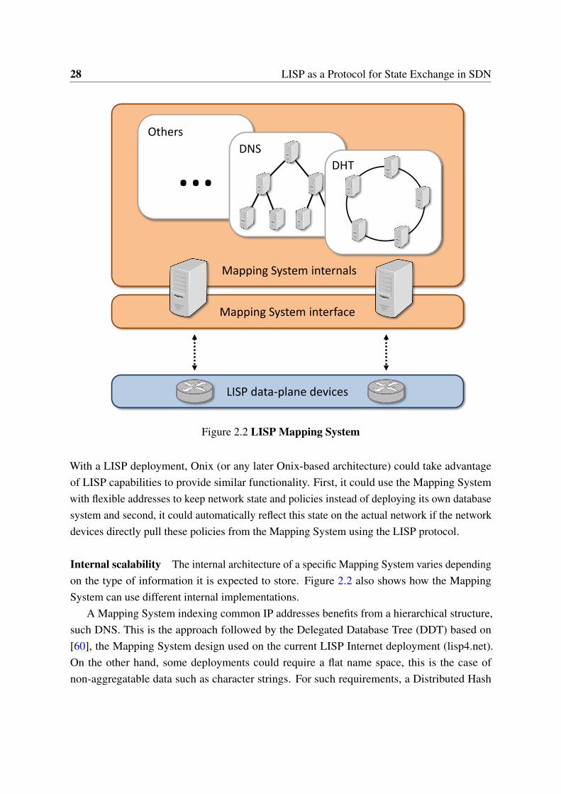
28 LISP as a Protocol for State Exchange in SDN
Mapping System interface
… DHT
DNS
Others
Mapping System internals
LISP data-plane devices
Figure 2.2 LISP Mapping System
With a LISP deployment, Onix (or any later Onix-based architecture) could take advantageof LISP capabilities to provide similar functionality. First, it could use the Mapping Systemwith flexible addresses to keep network state and policies instead of deploying its own databasesystem and second, it could automatically reflect this state on the actual network if the networkdevices directly pull these policies from the Mapping System using the LISP protocol.
Internal scalability The internal architecture of a specific Mapping System varies dependingon the type of information it is expected to store. Figure 2.2 also shows how the MappingSystem can use different internal implementations.
A Mapping System indexing common IP addresses benefits from a hierarchical structure,such DNS. This is the approach followed by the Delegated Database Tree (DDT) based on[60], the Mapping System design used on the current LISP Internet deployment (lisp4.net).On the other hand, some deployments could require a flat name space, this is the case ofnon-aggregatable data such as character strings. For such requirements, a Distributed Hash
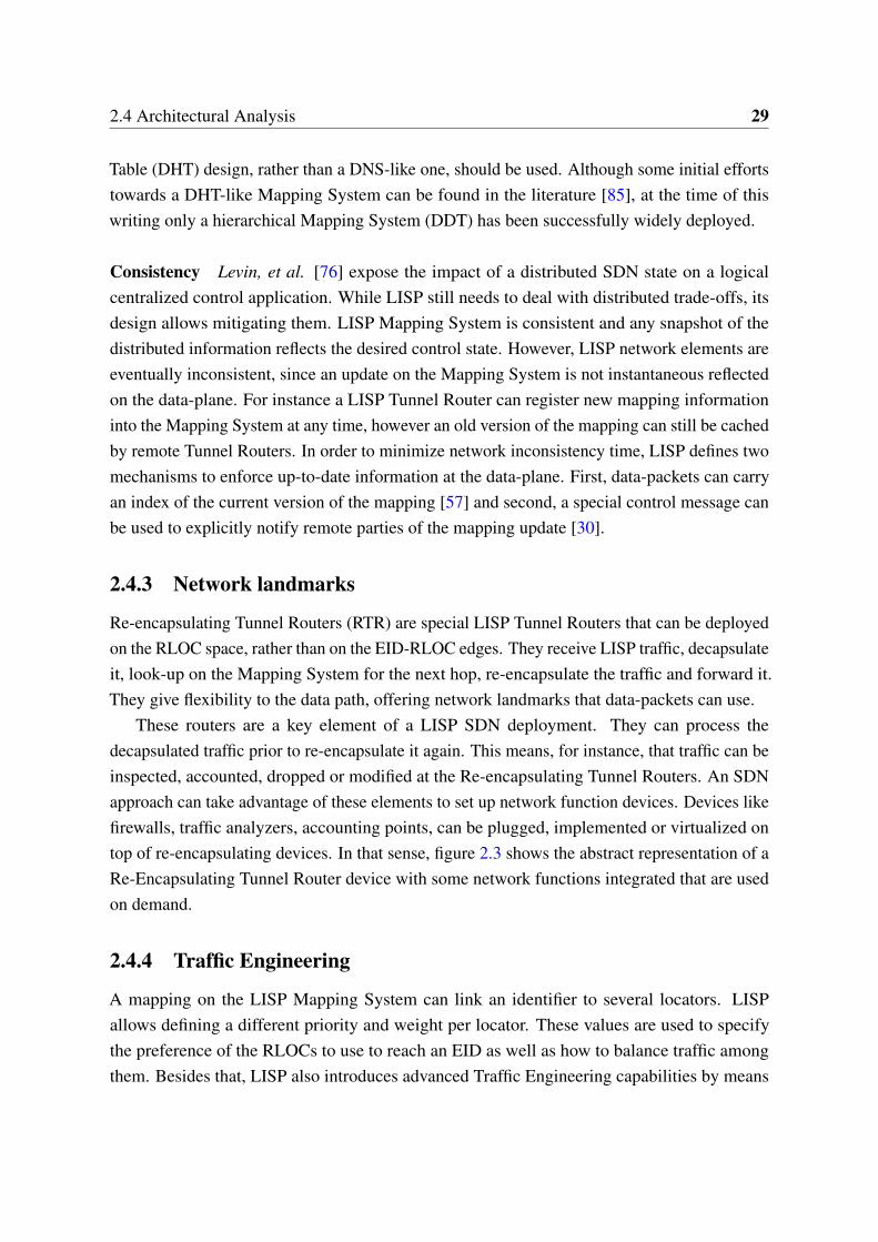
2.4 Architectural Analysis 29
Table (DHT) design, rather than a DNS-like one, should be used. Although some initial effortstowards a DHT-like Mapping System can be found in the literature [85], at the time of thiswriting only a hierarchical Mapping System (DDT) has been successfully widely deployed.
Consistency Levin, et al. [76] expose the impact of a distributed SDN state on a logicalcentralized control application. While LISP still needs to deal with distributed trade-offs, itsdesign allows mitigating them. LISP Mapping System is consistent and any snapshot of thedistributed information reflects the desired control state. However, LISP network elements areeventually inconsistent, since an update on the Mapping System is not instantaneous reflectedon the data-plane. For instance a LISP Tunnel Router can register new mapping informationinto the Mapping System at any time, however an old version of the mapping can still be cachedby remote Tunnel Routers. In order to minimize network inconsistency time, LISP defines twomechanisms to enforce up-to-date information at the data-plane. First, data-packets can carryan index of the current version of the mapping [57] and second, a special control message canbe used to explicitly notify remote parties of the mapping update [30].
2.4.3 Network landmarks
Re-encapsulating Tunnel Routers (RTR) are special LISP Tunnel Routers that can be deployedon the RLOC space, rather than on the EID-RLOC edges. They receive LISP traffic, decapsulateit, look-up on the Mapping System for the next hop, re-encapsulate the traffic and forward it.They give flexibility to the data path, offering network landmarks that data-packets can use.
These routers are a key element of a LISP SDN deployment. They can process thedecapsulated traffic prior to re-encapsulate it again. This means, for instance, that traffic can beinspected, accounted, dropped or modified at the Re-encapsulating Tunnel Routers. An SDNapproach can take advantage of these elements to set up network function devices. Devices likefirewalls, traffic analyzers, accounting points, can be plugged, implemented or virtualized ontop of re-encapsulating devices. In that sense, figure 2.3 shows the abstract representation of aRe-Encapsulating Tunnel Router device with some network functions integrated that are usedon demand.
2.4.4 Traffic Engineering
A mapping on the LISP Mapping System can link an identifier to several locators. LISPallows defining a different priority and weight per locator. These values are used to specifythe preference of the RLOCs to use to reach an EID as well as how to balance traffic amongthem. Besides that, LISP also introduces advanced Traffic Engineering capabilities by means
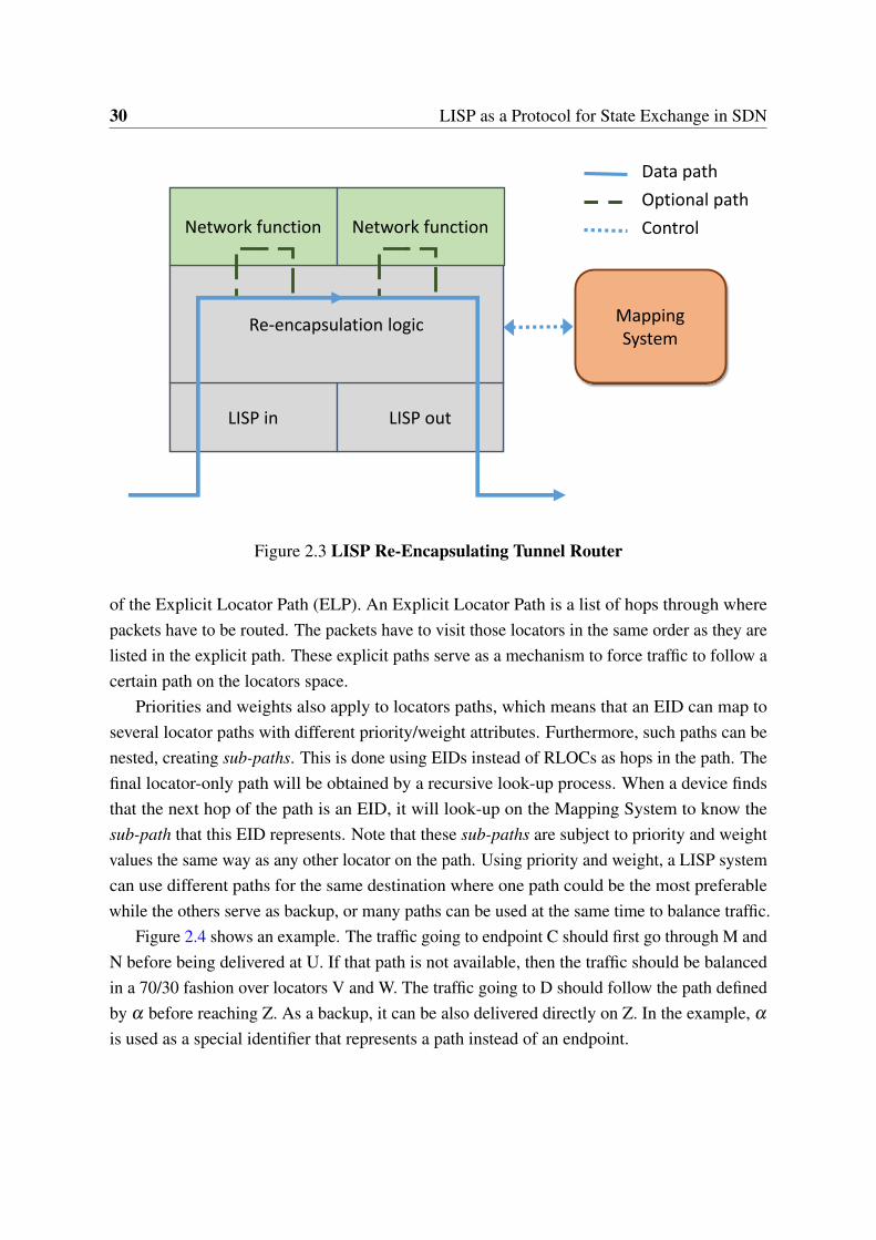
30 LISP as a Protocol for State Exchange in SDN
LISP in LISP out
Re-encapsulation logic
Network function Network function
MappingSystem
Data path
Optional path
Control
Figure 2.3 LISP Re-Encapsulating Tunnel Router
of the Explicit Locator Path (ELP). An Explicit Locator Path is a list of hops through wherepackets have to be routed. The packets have to visit those locators in the same order as they arelisted in the explicit path. These explicit paths serve as a mechanism to force traffic to follow acertain path on the locators space.
Priorities and weights also apply to locators paths, which means that an EID can map toseveral locator paths with different priority/weight attributes. Furthermore, such paths can benested, creating sub-paths. This is done using EIDs instead of RLOCs as hops in the path. Thefinal locator-only path will be obtained by a recursive look-up process. When a device findsthat the next hop of the path is an EID, it will look-up on the Mapping System to know thesub-path that this EID represents. Note that these sub-paths are subject to priority and weightvalues the same way as any other locator on the path. Using priority and weight, a LISP systemcan use different paths for the same destination where one path could be the most preferablewhile the others serve as backup, or many paths can be used at the same time to balance traffic.
Figure 2.4 shows an example. The traffic going to endpoint C should first go through M andN before being delivered at U. If that path is not available, then the traffic should be balancedin a 70/30 fashion over locators V and W. The traffic going to D should follow the path definedby α before reaching Z. As a backup, it can be also delivered directly on Z. In the example, α
is used as a special identifier that represents a path instead of an endpoint.
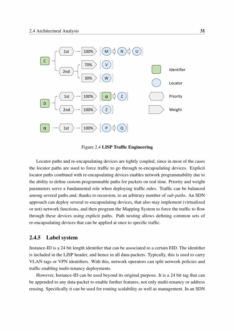
2.4 Architectural Analysis 31
M1st 100% N U
V
2nd
70%
W30%
Z
1st α
2nd
Z
D
C
100%
100%
P1st 100% Qα
Identifier
Locator
Priority
Weight
Figure 2.4 LISP Traffic Engineering
Locator paths and re-encapsulating devices are tightly coupled, since in most of the casesthe locator paths are used to force traffic to go through re-encapsulating devices. Explicitlocator paths combined with re-encapsulating devices enables network programmability due tothe ability to define custom programmable paths for packets on real time. Priority and weightparameters serve a fundamental role when deploying traffic rules. Traffic can be balancedamong several paths and, thanks to recursion, to an arbitrary number of sub-paths. An SDNapproach can deploy several re-encapsulating devices, that also may implement (virtualizedor not) network functions, and then program the Mapping System to force the traffic to flowthrough these devices using explicit paths. Path nesting allows defining common sets ofre-encapsulating devices that can be applied at once to specific traffic.
2.4.5 Label system
Instance-ID is a 24 bit length identifier that can be associated to a certain EID. The identifieris included in the LISP header, and hence in all data-packets. Typically, this is used to carryVLAN tags or VPN identifiers. With this, network operators can split network policies andtraffic enabling multi-tenancy deployments.
However, Instance-ID can be used beyond its original purpose. It is a 24 bit tag that canbe appended to any data-packet to enable further features, not only multi-tenancy or addressreusing. Specifically it can be used for routing scalability as well as management. In an SDN
32 LISP as a Protocol for State Exchange in SDN
proposal like Fabric [13], Instance-ID can be used to tag flows that should be forwarded inthe same way, simplifying forwarding on the core fabric and improving management andscalability.
2.5 Discussion
Based on the previous analysis, this section discusses the advantages and drawbacks of applyingLISP for SDN.
2.5.1 Highlights
Based on the analysis of Section 2.3 and Section 2.4 we highlight the most relevant features ofLISP in SDN environments.
• Scalability: As described on Section 2.3 and Section 2.4.2, the Mapping System andLISP connectionless pull-based signaling eases the scalability of LISP system. An SDNsolution can use LISP to provide a scalable network state database that can be directlyqueried by both data and control devices
• Interoperability: Given its flexible namespace (Section 2.4.1) and its label system (Section2.4.5), LISP is agnostic to the protocols it encapsulates and is well-suited to deploy cross-technology overlays.
• Inter-domain: Network landmarks (Section 2.4.3) and LISP traffic engineering capa-bilities (Section 2.4.4) allow LISP to enforce policies on transit networks and make itsuitable for inter-domain deployments.
2.5.2 Benefits
First LISP has been designed to be incrementally deployable and to leverage on current IP-basednetworks. Any existing IP-based network can incorporate common SDN features by simplyupgrading some routers to LISP Tunnel Routers and connecting them to a Mapping System.
Second, the shortcomings of traditional SDN protocols are motivating the emergence ofhybrid SDN proposals that combine SDN with traditional network solutions [140]. Interestingly,due to its scalability and interoperability LISP eases the deployment of the aforementionedhybrid SDN networks, specially since LISP can be incrementally deployed. Furthermore,thanks to its flexibility LISP is well-suited to accommodate future protocols and new networkapproaches.

2.5 Discussion 33
Finally, in contrast to common SDN protocols that are designed to operate mostly withina single domain, LISP allows SDN policies to be enforced across domains (e.g., DC-to-DC,DC-to-user’s home). Well-placed LISP elements (e.g., Re-encapsulating Tunnel Routers) makepossible a programmable SDN deployment over a transit network (e.g., the Internet), somethingthat is more complex to accomplish with traditional SDN protocols.
2.5.3 Drawbacks
Due to both how the protocol operates and its nature as a map-and-encap approach, LISP hassome limitations that must be taken into account when considering LISP as a southbound SDNprotocol.
• Extra headers: In order to encapsulate the traffic, LISP adds extra headers to the packets.This increments the packet size and reduces the available payload.
• Mapping resolution: LISP devices resolve and cache the mapping information on demand.The first packets of non-cached flows need to be either buffered or dropped until themapping resolution process has been completed.
• Mapping updates: Any update on the Mapping System is propagated over the network.However, this propagation involves some delay due to the signaling process. This canintroduce latency in the system and/or produce packet losses.
• Look-up support: While LISP defines how to convey different types of addresses incontrol messages, it does not define how to use all of those addresses to perform look-upoperations.
• Flat data support: Generally, Mapping System implementations have been designedwith hierarchical data in mind (e.g., IP addresses) and as such do not perform well whenstoring flat data (e.g., character strings).
Both Extra headers and Mapping Resolution drawbacks are inherent to the LISP architecture,however they do not have a strong impact on performance given that first, LISP encapsulationtypically adds only 36 bytes (IPv4) or 56 bytes (IPv6) [30], and second the LISP entities cachethe mappings and because of the strong locality of traffic [16] achieve a hit-rate above 99%.
Regarding Flat data support, the limitation can be solved with a DHT-based MappingSystem [85]. Given that the interface to read/write mappings is open and standard, thislimitation is not architectural and can be solved taking advantage of existing DHT databases.
To overcome the rest of the drawbacks we propose potential enhancements for the protocolin Section 2.5.4.
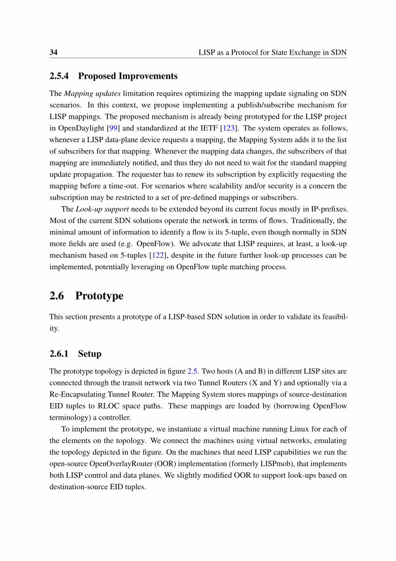
34 LISP as a Protocol for State Exchange in SDN
2.5.4 Proposed Improvements
The Mapping updates limitation requires optimizing the mapping update signaling on SDNscenarios. In this context, we propose implementing a publish/subscribe mechanism forLISP mappings. The proposed mechanism is already being prototyped for the LISP projectin OpenDaylight [99] and standardized at the IETF [123]. The system operates as follows,whenever a LISP data-plane device requests a mapping, the Mapping System adds it to the listof subscribers for that mapping. Whenever the mapping data changes, the subscribers of thatmapping are immediately notified, and thus they do not need to wait for the standard mappingupdate propagation. The requester has to renew its subscription by explicitly requesting themapping before a time-out. For scenarios where scalability and/or security is a concern thesubscription may be restricted to a set of pre-defined mappings or subscribers.
The Look-up support needs to be extended beyond its current focus mostly in IP-prefixes.Most of the current SDN solutions operate the network in terms of flows. Traditionally, theminimal amount of information to identify a flow is its 5-tuple, even though normally in SDNmore fields are used (e.g. OpenFlow). We advocate that LISP requires, at least, a look-upmechanism based on 5-tuples [122], despite in the future further look-up processes can beimplemented, potentially leveraging on OpenFlow tuple matching process.
2.6 Prototype
This section presents a prototype of a LISP-based SDN solution in order to validate its feasibil-ity.
2.6.1 Setup
The prototype topology is depicted in figure 2.5. Two hosts (A and B) in different LISP sites areconnected through the transit network via two Tunnel Routers (X and Y) and optionally via aRe-Encapsulating Tunnel Router. The Mapping System stores mappings of source-destinationEID tuples to RLOC space paths. These mappings are loaded by (borrowing OpenFlowterminology) a controller.
To implement the prototype, we instantiate a virtual machine running Linux for each ofthe elements on the topology. We connect the machines using virtual networks, emulatingthe topology depicted in the figure. On the machines that need LISP capabilities we run theopen-source OpenOverlayRouter (OOR) implementation (formerly LISPmob), that implementsboth LISP control and data planes. We slightly modified OOR to support look-ups based ondestination-source EID tuples.
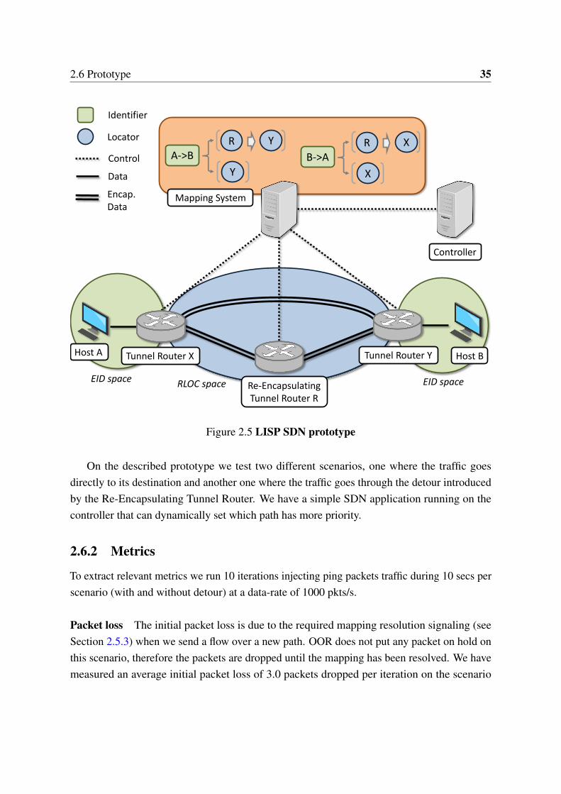
2.6 Prototype 35
Host A Host B
EID space EID spaceRLOC space
Controller
Control
Data
Tunnel Router X Tunnel Router Y
Re-EncapsulatingTunnel Router R
R Y
Y
A->B
Identifier
LocatorR X
X
B->A
Mapping SystemEncap. Data
Figure 2.5 LISP SDN prototype
On the described prototype we test two different scenarios, one where the traffic goesdirectly to its destination and another one where the traffic goes through the detour introducedby the Re-Encapsulating Tunnel Router. We have a simple SDN application running on thecontroller that can dynamically set which path has more priority.
2.6.2 Metrics
To extract relevant metrics we run 10 iterations injecting ping packets traffic during 10 secs perscenario (with and without detour) at a data-rate of 1000 pkts/s.
Packet loss The initial packet loss is due to the required mapping resolution signaling (seeSection 2.5.3) when we send a flow over a new path. OOR does not put any packet on hold onthis scenario, therefore the packets are dropped until the mapping has been resolved. We havemeasured an average initial packet loss of 3.0 packets dropped per iteration on the scenario
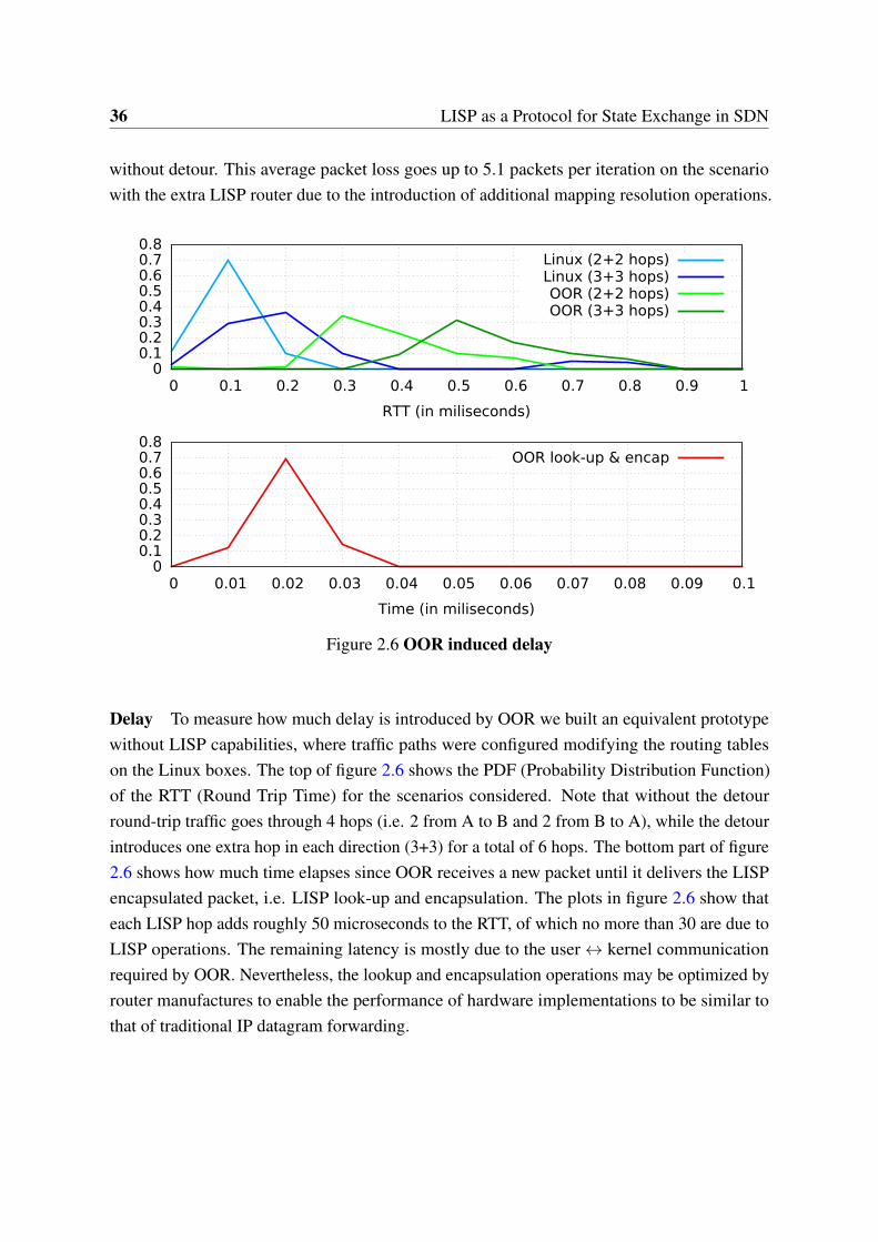
36 LISP as a Protocol for State Exchange in SDN
without detour. This average packet loss goes up to 5.1 packets per iteration on the scenariowith the extra LISP router due to the introduction of additional mapping resolution operations.
0 0.1 0.2 0.3 0.4 0.5 0.6 0.7 0.8
0 0.1 0.2 0.3 0.4 0.5 0.6 0.7 0.8 0.9 1
RTT (in miliseconds)
Linux (2+2 hops)Linux (3+3 hops)OOR (2+2 hops)OOR (3+3 hops)
0 0.1 0.2 0.3 0.4 0.5 0.6 0.7 0.8
0 0.01 0.02 0.03 0.04 0.05 0.06 0.07 0.08 0.09 0.1
Time (in miliseconds)
OOR look-up & encap
Figure 2.6 OOR induced delay
Delay To measure how much delay is introduced by OOR we built an equivalent prototypewithout LISP capabilities, where traffic paths were configured modifying the routing tableson the Linux boxes. The top of figure 2.6 shows the PDF (Probability Distribution Function)of the RTT (Round Trip Time) for the scenarios considered. Note that without the detourround-trip traffic goes through 4 hops (i.e. 2 from A to B and 2 from B to A), while the detourintroduces one extra hop in each direction (3+3) for a total of 6 hops. The bottom part of figure2.6 shows how much time elapses since OOR receives a new packet until it delivers the LISPencapsulated packet, i.e. LISP look-up and encapsulation. The plots in figure 2.6 show thateach LISP hop adds roughly 50 microseconds to the RTT, of which no more than 30 are due toLISP operations. The remaining latency is mostly due to the user ↔ kernel communicationrequired by OOR. Nevertheless, the lookup and encapsulation operations may be optimized byrouter manufactures to enable the performance of hardware implementations to be similar tothat of traditional IP datagram forwarding.
2.7 Conclusions 37
2.7 Conclusions
In this chapter we have analyzed if LISP -as is- can be used for SDN. Our analysis concludesthat the control-data decoupling, the network programability and the centralized control enabledby traditional SDN solutions are already enabled by the LISP Mapping System and supportedby the rest of the LISP components. The major benefits of using LISP for SDN are that it keepsits incremental deployability and flexibility while providing scalability, interoperability andinter-domain support, making LISP specially suitable for SDN deployments over legacy ortransit networks, such the Internet. However, despite its potential as an SDN enabler, there aresome aspects of the protocol that should be extended to better fit the SDN use-case, mainly thesignaling for the mapping updates and implementing support for advanced look-up process.Finally, the presented prototype demonstrates that LISP is feasible for SDN scenarios.

Chapter 3
Asynchronous SDN Architecture forEnd-Nodes
The advent of SDN has brought a plethora of new architectures and controller designs for manyuse-cases and scenarios. Existing SDN deployments focus on campus, datacenter and WANnetworks. However, little research efforts have been devoted to the scenario of effectivelycontrolling a full deployment of end-nodes (e.g. mobile devices, home routers, etc.) that aretransient and scattered across the Internet. In this chapter we present a rigorous analysis of thechallenges associated with an SDN architecture for end-nodes, show that such challenges arenot found in existing SDN scenarios, and provide practical design guidelines to address them.Then, and following these guidelines we present an decoupled-state architecture specificallydesigned for the end-nodes scenario. This architecture is based on the combination of adistributed controller with an intent-driven northbound and a decoupled Network InformationBase provisioned with a connectionless pull-oriented southbound. Finally, we measure aproof-of-concept deployment to assess the validity of the analysis as well as the architecture.
3.1 Introduction
In the recent years the Software-Defined Networking (SDN) [74] paradigm has been appliedto different scenarios, namely campus, datacenter and WAN networks [74, 71, 5]. However,little research efforts have been devoted to scenarios where the controlees are end-nodes, e.g.mobile nodes (smartphones, tablets, etc), personal computers, home or SOHO (Small Officeor Home Office) routers, etc. Despite the scarce literature on the topic, we believe that anSDN architecture designed for end-nodes enables interesting use-cases, since companies andoperators can push policies and control the traffic from its very origin.
40 Asynchronous SDN Architecture for End-Nodes
However, this novel SDN scenario brings a set of challenges that are not found in existingSDN deployments or that are strongly exacerbated in the end-nodes case. On one hand, thenumber of controlees is very large and they are typically scattered through various networks,this imposes very high scalability and availability requirements to the controller. On the otherhand, this scenario comes with a high churn, since end-nodes are transient and mobile andmight connect and disconnect randomly [29]. Finally, the architecture has to face an additionalcomplexity burden to operate the data-plane. As opposed to transit routers and switches,end-nodes do not aggregate traffic and thus, require fine-grain policies.
In this chapter we analyze the challenges of deploying SDN for end-nodes and discusspractical design guidelines. As a result, we present a specific architecture based on a decentral-ized and symmetric controller with an intent-driven northbound and a pull-based southbound.We discuss the implications of the architecture and provide a proof-of-concept prototype thatshows the validity of the analysis and the feasibility of the architecture. To conclude the chapterwe provide a quantitative comparison of the proposed architecture with relevant related work.
3.2 Use-Cases
Network administrators can enhance the effective control that they have over end-nodes byprovisioning them with SDN-capabilities. This entitles to extend the fine-grain control andcentralized management enabled by SDN to the very end of the network. We can differentiatethree different use-cases categories.
Source control SDN capabilities at end-nodes enable dynamic and remote control of theirinterfaces, which enables centralized management for load balancing and bandwidth aggrega-tion. An operator would be able to balance a smartphone’s traffic between Wi-Fi and cellularinterfaces based on business agreements, remaining battery and/or device’s geo-location (e.g.avoid traffic over cellular network when abroad). A remote backup company can leverage onmulti-homed end-nodes to aggregate the bandwidth of all available interfaces and speed uptransmissions.
Destination control SDN for end-nodes enables simpler and fine-grain control on the trafficdestination. For instance, a content provider can detour traffic to one datacenter or anotherbased on central control per end-node basis (e.g. to offer personalized content per end-user).Similarly, another company can offer remote VPN (Virtual Private Network) management onthe devices of its employees dynamically tunneling the traffic depending on the destination (e.g.to decide on-the-fly which traffic should be encrypted).
3.3 Challenges 41
Path control : Path control can be achieved by combining SDN-capable end-nodes withsome well-placed SDN nodes on transit networks. This allows companies to steer trafficthrough transit SDN nodes to, for instance, optimize routing or apply in-path functions. As anexample, a parental filtering company can make use of such capabilities to filter traffic going tothe end-nodes and block inappropriate content.
3.3 Challenges
Achieving SDN support at the end-nodes is not straightforward since it presents a set of novelchallenges when compared to existing SDN deployments. First of all, there is a high numberof controlees, potentially reaching hundreds of thousands of nodes. Although existing SDNdeployments may handle a large number of controlees, this burden is heightened in the end-nodescenario when combined with the rest of its challenges.
In addition, in existing SDN deployments controlees are physically connected to the SDNnetwork, however in the end-nodes scenario the controlees are attached to legacy networksat the edge. Such networks are usually out of the administrative control of the SDN domain.Moreover, the controlees are scattered over these edge networks, potentially at a worldwidescale.
Furthermore, the discussed scenario suffers from a high churn since end-nodes are transientand highly mobile, this makes a difference with regular SDN where typically controlees arestationary and always available. Besides, and contrary to common SDN devices, end-nodesare subject to high heterogeneity in terms of capabilities and conditions (e.g. geo-location,spectrum usage, remaining battery, etc). Finally, end-nodes have to face lower traffic localityin contrast to typical SDN devices that usually aggregate traffic and take advantage of this tospeedup data-plane performance using caches, wildcards and/or longest prefix matches.
3.4 Design Guidelines
The resulting design principles to overcome the scenario challenges are summarized in Table3.1. First, an overlay approach that encapsulates traffic at the data-plane is required to bypassin-place networks and to offer a homogeneous view of the heterogeneous controlees. To be ableto encapsulate overlay traffic into underlay packets, the end-node has to retrieve the appropriaterules by querying the NIB (Network Information Base), term that we borrow from [71]. Due tothe large number of data-plane nodes and the low traffic locality, this generates a high ratioof requests from the southbound to the NIB. Therefore, the controller must be able to scale-out to accommodate this very high volume of messages, while remaining decentralized and
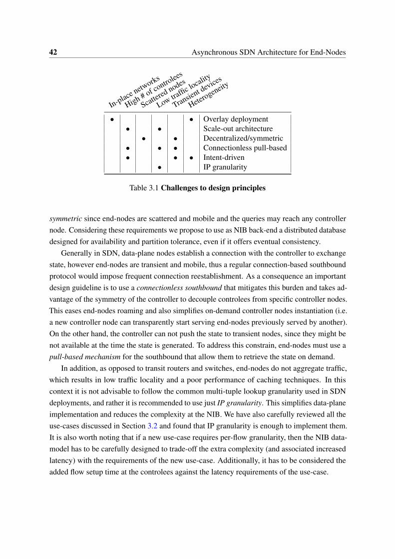
42 Asynchronous SDN Architecture for End-Nodes
In-place networks
High # of controlees
Scattered nodes
Low traffic locality
Transient devices
Heterogeneity
• • Overlay deployment• • Scale-out architecture
• • Decentralized/symmetric• • • Connectionless pull-based• • • Intent-driven
• IP granularity
Table 3.1 Challenges to design principles
symmetric since end-nodes are scattered and mobile and the queries may reach any controllernode. Considering these requirements we propose to use as NIB back-end a distributed databasedesigned for availability and partition tolerance, even if it offers eventual consistency.
Generally in SDN, data-plane nodes establish a connection with the controller to exchangestate, however end-nodes are transient and mobile, thus a regular connection-based southboundprotocol would impose frequent connection reestablishment. As a consequence an importantdesign guideline is to use a connectionless southbound that mitigates this burden and takes ad-vantage of the symmetry of the controller to decouple controlees from specific controller nodes.This eases end-nodes roaming and also simplifies on-demand controller nodes instantiation (i.e.a new controller node can transparently start serving end-nodes previously served by another).On the other hand, the controller can not push the state to transient nodes, since they might benot available at the time the state is generated. To address this constrain, end-nodes must use apull-based mechanism for the southbound that allow them to retrieve the state on demand.
In addition, as opposed to transit routers and switches, end-nodes do not aggregate traffic,which results in low traffic locality and a poor performance of caching techniques. In thiscontext it is not advisable to follow the common multi-tuple lookup granularity used in SDNdeployments, and rather it is recommended to use just IP granularity. This simplifies data-planeimplementation and reduces the complexity at the NIB. We have also carefully reviewed all theuse-cases discussed in Section 3.2 and found that IP granularity is enough to implement them.It is also worth noting that if a new use-case requires per-flow granularity, then the NIB data-model has to be carefully designed to trade-off the extra complexity (and associated increasedlatency) with the requirements of the new use-case. Additionally, it has to be considered theadded flow setup time at the controlees against the latency requirements of the use-case.
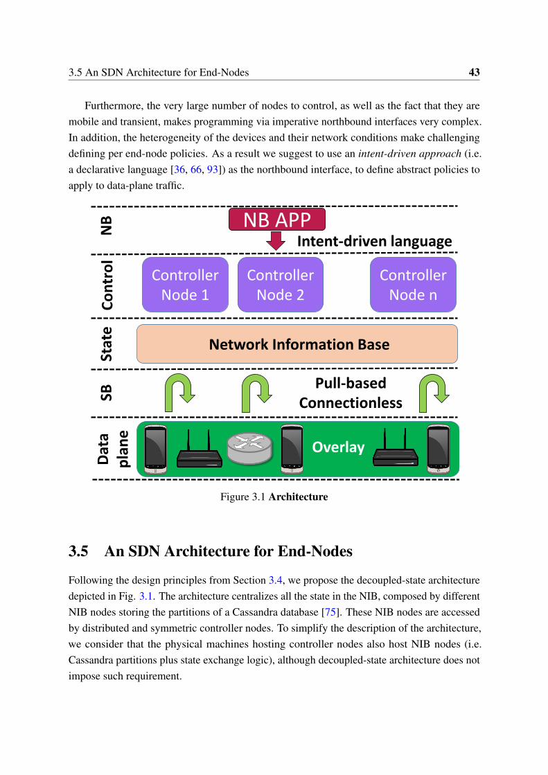
3.5 An SDN Architecture for End-Nodes 43
Furthermore, the very large number of nodes to control, as well as the fact that they aremobile and transient, makes programming via imperative northbound interfaces very complex.In addition, the heterogeneity of the devices and their network conditions make challengingdefining per end-node policies. As a result we suggest to use an intent-driven approach (i.e.a declarative language [36, 66, 93]) as the northbound interface, to define abstract policies toapply to data-plane traffic.
Network Information Base
Controller Node 1
Overlay
Pull-basedConnectionless
Intent-driven languageNB APP
Dat
ap
lan
eN
BC
on
tro
lSB
Controller Node 2
Controller Node n
Stat
e
Figure 3.1 Architecture
3.5 An SDN Architecture for End-Nodes
Following the design principles from Section 3.4, we propose the decoupled-state architecturedepicted in Fig. 3.1. The architecture centralizes all the state in the NIB, composed by differentNIB nodes storing the partitions of a Cassandra database [75]. These NIB nodes are accessedby distributed and symmetric controller nodes. To simplify the description of the architecture,we consider that the physical machines hosting controller nodes also host NIB nodes (i.e.Cassandra partitions plus state exchange logic), although decoupled-state architecture does notimpose such requirement.
44 Asynchronous SDN Architecture for End-Nodes
The controller nodes offer an intent-driven northbound based on the GBP (Group BasedPolicy) [41] project to the control applications. The NIB nodes offer a connectionless pull-basedsouthbound implemented via LISP (Locator/ID Separation Protocol) [30, 126] to the data-planenodes. The data-plane nodes are provisioned with encapsulation capabilities to join a commonoverlay.
3.5.1 Northbound
The policies are enforced from the northbound using a declarative intent-driven language thatis rendered at the controller to generate the data-plane state stored in the NIB. In particular wepropose to use a group-oriented declarative language given that related nodes will likely sharethe same policies. To ease the implementation of the architecture we use the OpenStack [106]backed GBP project as the northbound language since we can leverage on its already definedsyntax. Although, depending on the specific use-case, its syntax may need to be extended tosupport further primitives (e.g. geo-location).
In the GBP language, end-nodes belong to groups and policies define how to prioritize links,balance traffic or chain hops on the underlay. The policies can be defined for a pair of groups,when one sends traffic to the other, or in general for the group’s default ingress and egresspolicies, thus avoiding defining all possible group pairs. For instance, a particular use-case candefine the groups Employees’ Laptops and West Coast Office with the following default policies,Employees’ laptops should use Ethernet for egress traffic and West Coast Office ingress trafficshould be balanced between Link-1 and Link-2. However, the use-case may also define thatwhen the traffic from Employees’ Laptops goes to West Coast Office it should use LTE as egress,pass trough hop Firewall and use Link-3 as ingress. More complex groups are possible, suchEmployees’ Laptops with battery below 15%, however complex use-cases require carefullydesign, see Section 3.6.1.
3.5.2 Controller
The controller is supported by distributed, decentralized and symmetric nodes as the onedepicted in Fig. 3.2. They have an intent parser module that processes the northbound policesthat result in NIB state. The bootstrap module is used to initialize via NETCONF (NetworkConfiguration Protocol) [24] data-plane nodes.
The controller nodes receive abstract policies from the northbound and render them intospecific state to be stored at the NIB nodes. All the controller nodes have a connection to aCassandra database where the NIB is stored. The controller nodes coordinate among themselvesusing a ZooKeeper [56] subsystem.
3.5 An SDN Architecture for End-Nodes 45
System Scalability
The architecture is able to scale-out using the Cassandra backend and symmetric design forboth the controller and NIB nodes. On one hand, the NIB is stored in Cassandra and thus thesystem state will scale as good as Cassandra does. On the other hand, the controller and NIBnodes have been designed to be analogous and to be used indifferently, and since they are allconnected to the same Cassandra back-end, they can all access the same state.
Since all the controller and NIB nodes are interchangeable and offer the same functionality,the system can be scaled-out smoothly and presents no single point of failure. If the numberof controlees or the ratio of northbound operations increases, the controller can automaticallycoordinate (via the ZooKeeper subsystem) the instantiation of a new NIB node or a newcontroller node to redistribute the load.
This process is transparent to the data-plane nodes. From the southbound point of view,data-plane nodes will detect an overloaded (or down) NIB node by the lack of acknowledgmentof their southbound requests and will eventually switch to a different one. This automaticallybalances the load across different nodes. The distributed and symmetric schema for the NIBnodes also encourages data-plane nodes to communicate with the NIB node that offers lesslatency and to seamlessly move to a different one if needed.
It is also interesting to point that the state cached in data-plane nodes, and the ephemeralstate at the NIB (e.g. the list data-plane nodes registered) will eventually expire and beautomatically removed. This solves the problem of unnecessary state stored that can burden thesystem performance and/or increase query time.
3.5.3 Network Information Base (NIB)
Each NIB node stores a Cassandra partition and is provisioned with a LISP interface, as shownin Fig. 3.2. Among the available NoSQL databases we choose Cassandra [75] as the back-endfor the NIB since it is a general purpose database that offers huge scalability and almost constantquery latency time regardless of the size of the stored state [119], see Section 3.6.2. Via a LISPinterface each NIB node can exchange state with the southbound nodes.
Information Tables
For the scenario considered, the NIB does not need to represent a complete view of the networktopology, just the relations and interactions among the groups and the nodes belonging tothem. To that end, the NIB stored in Cassandra comprises three main tables, nodes, groups andpaths. Queries to the NIB will result (through one or more database queries) into rendered statespecific to the requester node (see Section 3.6.1).
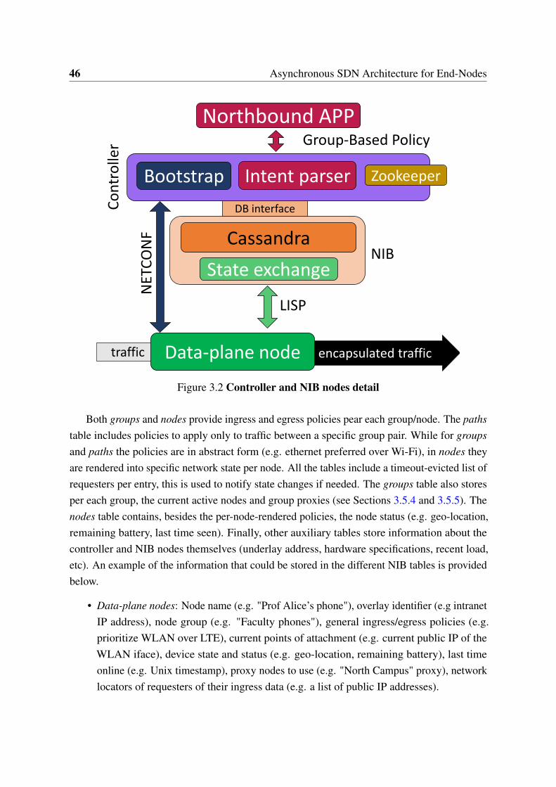
46 Asynchronous SDN Architecture for End-Nodes
DB interface
Data-plane node
LISP
Northbound APPGroup-Based Policy
State exchange
Bootstrap
NET
CO
NF
Zookeeper
traffic encapsulated traffic
Intent parser
CassandraNIB
Co
ntr
olle
r
Figure 3.2 Controller and NIB nodes detail
Both groups and nodes provide ingress and egress policies pear each group/node. The pathstable includes policies to apply only to traffic between a specific group pair. While for groupsand paths the policies are in abstract form (e.g. ethernet preferred over Wi-Fi), in nodes theyare rendered into specific network state per node. All the tables include a timeout-evicted list ofrequesters per entry, this is used to notify state changes if needed. The groups table also storesper each group, the current active nodes and group proxies (see Sections 3.5.4 and 3.5.5). Thenodes table contains, besides the per-node-rendered policies, the node status (e.g. geo-location,remaining battery, last time seen). Finally, other auxiliary tables store information about thecontroller and NIB nodes themselves (underlay address, hardware specifications, recent load,etc). An example of the information that could be stored in the different NIB tables is providedbelow.
• Data-plane nodes: Node name (e.g. "Prof Alice’s phone"), overlay identifier (e.g intranetIP address), node group (e.g. "Faculty phones"), general ingress/egress policies (e.g.prioritize WLAN over LTE), current points of attachment (e.g. current public IP of theWLAN iface), device state and status (e.g. geo-location, remaining battery), last timeonline (e.g. Unix timestamp), proxy nodes to use (e.g. "North Campus" proxy), networklocators of requesters of their ingress data (e.g. a list of public IP addresses).
3.5 An SDN Architecture for End-Nodes 47
• Groups: Group name (e.g. "Faculty phones"), overlay identifier (e.g. intranet IP prefix),general policies per group (e.g. prioritize WLAN over cellular networks), policies toconnect to other groups (e.g. when connecting to "Office network" use LTE), proxy nodesto use by its members (e.g. "North Campus" proxy), data-plane nodes belonging to thegroup (e.g. "Prof Alice’s phone", "Ass. Prof. Bob’s phone"), current active data-planenodes (e.g. "Prof Alice’s phone").
• Paths: Path name (e.g. "Secure access to office"), group-pair connected by the path(e.g. "Faculty phones" to "Office network"), overlay identifier (e.g. phones prefix tooffice prefix tuple), path-specific policies (e.g. overwrite interface priorities and prioritizeLTE), path logical hops (e.g. "CS building" gateway → "Firewall" → "Office network"gateway), network locators of requesters of the path (e.g. a list of public IP addresses).
• Controller/NIB nodes: Location (e.g. public IP), hardware and network specifications(e.g. memory size, link throughput), average recent load (e.g. low).
State consistency
To keep the state updated at the NIB, data-plane nodes send periodical keep-alive LISP controlmessages registering their current status (e.g. battery, geo-location) at the NIB. These controlmessages can also be triggered as a response to a data-plane event. When there is a state updatefrom a data-plane node (e.g. an interface goes down) the end-node sends an update to theNIB and notifies other interested data-plane nodes of the change (e.g. peers with which it iscommunicating).
When the state update comes from a northbound application (e.g. a modified group policychanges the interface priorities for a set of nodes) the controller renders the new state andinstalls it at the NIB. The insertion of new state may activate some database mechanisms thattrigger state consistency callback operations (see [136] for details). Using this, the NIB notifiesvia the LISP protocol the state change to the data-plane nodes affected by it. If the changemodifies state that other data-plane nodes may have cached, the NIB notifies those too (e.g. anode new ingress policy is notified to its requesters). Besides, the NIB has also to verify if anynew state introduced by the northbound (e.g. creation of a path policy for a group-pair) shouldoverwrite state previously cached at data-plane nodes (e.g. general destination-based cachedstate), in that case the NIB notifies the relevant parties of the insertion of this new state.
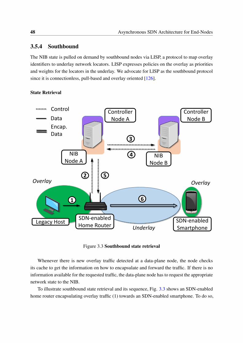
48 Asynchronous SDN Architecture for End-Nodes
3.5.4 Southbound
The NIB state is pulled on demand by southbound nodes via LISP, a protocol to map overlayidentifiers to underlay network locators. LISP expresses policies on the overlay as prioritiesand weights for the locators in the underlay. We advocate for LISP as the southbound protocolsince it is connectionless, pull-based and overlay oriented [126].
State Retrieval
Legacy HostSDN-enabled Home Router
Controller Node A
Overlay Overlay
UnderlaySDN-enabled Smartphone
Control
Data
Encap.Data
Controller Node B
NIBNode B
NIBNode A
Figure 3.3 Southbound state retrieval
Whenever there is new overlay traffic detected at a data-plane node, the node checksits cache to get the information on how to encapsulate and forward the traffic. If there is noinformation available for the requested traffic, the data-plane node has to request the appropriatenetwork state to the NIB.
To illustrate southbound state retrieval and its sequence, Fig. 3.3 shows an SDN-enabledhome router encapsulating overlay traffic (1) towards an SDN-enabled smartphone. To do so,
3.5 An SDN Architecture for End-Nodes 49
the home router requests the appropriate state to its nearest NIB node via the LISP protocol (2).In the example depicted, the required state is not stored in the queried node and thus has to beobtained from another Cassandra partition (3)(4). The state is then sent to the home router (5)which uses it to encapsulate the overlay traffic through the underlay (6).
Generally, state requests include overlay traffic source and destination. Some use-cases mayinclude also port or protocol information, or even end-node details, such as current geo-locationor wireless channel(s) in use. For most of the use-cases, the NIB tries first to find if there is apath available for the source-destination group-pair, if none is available it will then return thedefault ingress policies of the destination. Different use-cases may require extra informationand NIB processing, but in all cases the reply from the NIB (that the data-plane node caches)only contains source-destination based state (i.e. IP granularity). Moreover, if the data-planenode is a standalone end-node (e.g. a smartphone), it can disregard source information andindex just by destination.
Finally, the NIB stores the network locator of the requester to notify updates if needed. Thisrequester data will eventually expire, therefore the data-plane node has to request periodicallythe state to refresh this cache or to update its stored network locator (for instance, in the case ofa handover event).
While the state is being retrieved, the data-plane node can choose to either buffer the traffic(if the node has available resources) or rather encapsulate the traffic towards a re-encapsulationnode. These re-encapsulation nodes have larger hardware capabilities and can offer morebuffering. In addition, they are provisioned per-group and therefore they can aggregate traffic,resulting in a high cache hit ratio.
3.5.5 Data-Plane
The architecture considers all data-plane nodes alike, regardless if they are smartphones, homerouters or, for instance, datacenter gateways.
End-Nodes Bootstrap
Data-plane nodes should be statically provisioned beforehand with their overlay address -orprefix- and the address of at least one controller node. How this provision is done is out to thescope of the architecture, it could be factory settings, based on node specifications or configuredby the user. Data-plane node use the controller address to retrieve bootstrap configurationvia NETCONF. Once the bootstrap is done, any future control communication will be doneconnectionless via LISP signaling. During the bootstrap, the controller provisions the nodes
50 Asynchronous SDN Architecture for End-Nodes
with an up-to-date list of NIB nodes, the list of their proxy nodes (see Sections 3.5.4 and 3.5.5),and the default egress policies for their data-plane traffic.
Overlay Encapsulation
The architecture is agnostic to the specific encapsulation format used -e.g. VxLAN (VirtualExtensible Local Area Network) [83]- and the choice must be made per use-case basis. The en-capsulation chosen partially defines the rendered state that the NIB stores and the configurationto be provided during the bootstrap.
Traffic encapsulation entitles to circumvent the traffic policies of the underlay and applyoverlay policies instead. Different priorities and weights can be set for underlay locators andthus overlay routing can be enforced. Moreover, SDN-controlled data-plane elements can bedeployed in transit networks to help to bypass underlay out-of-scope policies. Re-encapsulatingdata-plane packets at these nodes enables to effectively detour traffic. In order to use them,re-encapsulating nodes are added as intermediate hops in certain path policies.
On the other hand, if a data-plane node needs to communicate to a host outside the overlaynamespace it can redirect the traffic to a proxy node connected to the legacy Internet. The proxynode receives the traffic and takes care of decapsulating it and applying any NAT (NetworkAddress Translation) operation required (if the overlay traffic is not routable in the publicInternet).
3.6 Discussion
3.6.1 Use-Cases Complexity
Complex use-cases results in more database queries and potentially less parallelization of suchqueries. The consequence is increased latency per request and more database nodes needed. Forinstance, a use-case where groups depend on remaining battery and current geo-location makesnecessary to obtain first the proper group prior to query for group-based path policies. Thearchitecture has to keep a balance between the complexity of the queries (defined by the usecase), the number of southbound requests (defined by the traffic and its locality), the maximumlatency accepted and the number of database nodes. This trade-off has to be carefully analyzedper use-case.
In the case of the PoC presented in this work in section 3.7 the database consumes thetime of one select operation per southbound state request. The main reason is that we useIP addresses both to identify groups and nodes. This allows us not only to use directly theinformation carried in the request to query the database without any pre-processing, but also
3.6 Discussion 51
to take advantage of parallelization to obtain at the same time group-based source-destinationpolicies and destination-only default ingress policies. Other use-cases that may not takeadvantage of such optimization (e.g., groups depending on the remaining battery) may needtwo or more sequential select operations (first to find the group and then the group-based path).
3.6.2 NIB Scalability
From our analysis and proof-of-concept we conclude that the main bottleneck of the systemis at the NIB, specifically at the database state-retrieval, given that the NIB has to support thescalability requirements of the scenario. The NIB can be overloaded by the huge amount ofnodes pulling state, although this strongly depends on the characteristics of the use-case andthe complexity of the associated queries. Complex use-cases will require more (and potentiallymore complex) queries and thus will impose more burden in the NIB.
To allocate the requirements of different use-cases, we have chosen Cassandra as the NIBback-end since it is a general-purpose database that ensures constant latency times regardlessof the number of entries stored. Furthermore, it offers an operations per second ratio linear tothe number of database nodes. The authors of [119] show that under a stressful benchmarkwith mostly read/scan operations, Cassandra is capable of keeping a latency of 20 ms and athroughput of 20K operations per second on a 4-node cluster storing a dataset with millions ofentries. In a 12-node cluster the throughput goes up to almost 60K operations per second.
3.6.3 Security and Privacy
In the scenario and architecture discussed, the control of the end-nodes is partially relinquishedto the operator of the SDN infrastructure (e.g the network operator, the company owning theend-device or a third party providing SDN-based services). There is a tradeoff between thebenefits brought by the SDN architecture and the lack of control at the end-node. This mayresult in security and privacy concerns for end-users.
In general, SDN advocates for decoupling and centralizing the control. Thus, the lack ofcontrol at the data-plane devices is not exclusive to the end-node scenario. Users have to decideif they are willing to trust their SDN providers in the same way that they trust, for instance, themanufacturer of their smartphone. However, under certain conditions privacy may enhanced byadapting some of the mechanisms proposed in [124] and explained in Chapter 5.

52 Asynchronous SDN Architecture for End-Nodes
3.6.4 Architecture Resilience
The keep-alive southbound signaling will detect failures at data-plane nodes and update theNIB state. Moreover, LISP supports active data-plane probing and if a problem is detected,nodes can fast fail-over to backup data-plane policies. NIB-level failures are covered byCassandra background data-recovering mechanisms and ZooKeeper coordination will detectand re-instantiate any down controller or NIB node if needed.
3.6.5 Signaling Overhead
Mobility generates frequent state updates, however this has to be notified to just a few nodes:the requesters of the particular mobile node. On the other hand northbound policy changes (e.g.,a new ingress policy for a datacenter) will generate a large amount of notifications, howeverit is expected that such changes occur less frequently. In addition, the use-cases consideredin section 3.2 can operate well with partially outdated state for a certain period, this is nottypically possible in existing SDN deployments.
3.7 Proof of Concept
3.7.1 Setup
Figure 3.4 PoC topology
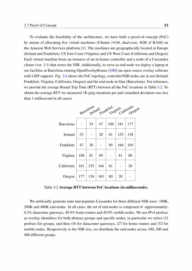
3.7 Proof of Concept 53
To evaluate the feasibility of the architecture, we have built a proof-of-concept (PoC)by means of allocating five virtual machines (Ubuntu 14.04, dual-core, 4GB of RAM) onthe Amazon Web Services platform [1]. The machines are geographically located at Europe(Ireland and Frankfurt), US East Coast (Virginia) and US West Coast (California and Oregon).Each virtual machine hosts an instance of an in-house controller and a node of a Cassandracluster (ver. 3.1) that stores the NIB. Additionally, to serve as end-node we deploy a laptop atour facilities at Barcelona running OpenOverlayRouter [100] (an open-source overlay softwarewith LISP support). Fig. 3.4 shows the PoC topology, controller/NIB nodes are in red (Ireland,Frankfurt, Virginia, California, Oregon) and the end-node in blue (Barcelona). For reference,we provide the average Round Trip Time (RTT) between all the PoC locations in Table 3.2. Toobtain the average RTT we measured 1K ping iterations per pair (standard deviation was lessthan 1 millisecond in all cases).
Barcelona
IrelandFrankfurt
VirginiaCalifo
rnia
Oregon
Barcelona - 53 47 108 181 177
Ireland 53 - 20 81 155 138
Frankfurt 47 20 - 89 166 165
Virginia 108 81 89 - 81 80
California 181 155 166 81 - 20
Oregon 177 138 165 80 20 -
Table 3.2 Average RTT between PoC locations (in milliseconds).
We artificially generate state and populate Cassandra for three different NIB sizes: 100K,200K and 400K end-nodes. In all cases, the set of end-nodes is composed of -approximately-0.2% datacenter gateways, 49.9% home routers and 49.9% mobile nodes. We use IPv4 prefixesas overlay identifiers for both abstract groups and specific nodes, in particular we select /12prefixes for groups, and then /16 for datacenter gateways, /27 for home routers and /32 formobile nodes. Respectively to the NIB size, we distribute the end-nodes across 100, 200 and400 different groups.
54 Asynchronous SDN Architecture for End-Nodes
3.7.2 Experiments
To asses the PoC implementation, we run three different experiments. First, we generate trafficin our end-node addressed to end-nodes stored in the NIB and measure the time the end-nodetakes to retrieve the appropriate routing policies from the NIB. We configure our end-node inBarcelona to use the NIB node in Ireland. For each of the three different NIB sizes we generate15K unique flows. We plot the latency results as Cumulative Distribution Functions (CDF) inFig. 3.5. The results show that the latency is independent of the NIB size, which is coherentwith the discussion in Section 3.6.2. The figure also shows that the latency has a constantcomponent (NIB processing and NIB to end-node transmission) and then a variable component,depending on from which Cassandra partition the state has to be retrieved. Latency values tendto cluster around roughly three points, that can be associated with the different delays involvedto retrieve state stored in either Europe, US West or US East.
For a second experiment, we update the NIB state through the northbound and measure thetime since the controller node (at Ireland) receives the northbound message until the NIB nodecollocated within the same VM sends the state-updated notification to the southbound. Foreach NIB size, we update state for 15K different end-nodes and plot the CDF in Fig. 3.6. Thefigure resembles Fig. 3.5 since most of the latency is due again to the network transmissiondelay between the different Cassandra nodes. Northbound update time is measured directly atthe controller node and thus no latency is induced by the NIB to end-node transmission. Thismakes Fig. 3.6 to be shifted to the left around 50ms (Barcelona-Ireland RTT) when comparedto Fig. 3.5. Besides, both Fig. 3.5 and Fig. 3.6 show minor latency variation across NIBsizes. This is due to the variation of network conditions over different iterations (since thePoC runs over the Internet) and to the randomness introduced during the process of generatingtraffic/updates.
Finally, we perform a test where we bootstrap the end-node and measure the time since itnotifies its presence to the controller until the end-node acknowledges correct configurationinstalled. In this case the end-node uses a random controller node on each iteration. We perform7K iterations for the worst-case of 400K end-nodes. In the bootstrap case, the latency dependsnot only on Cassandra delay, but also on the NETCONF communication between the controllerand the end-node. This explains why the slope is softer in Fig. 3.7. Nevertheless, it is stillpossible to identify clustering regions, depending on how close the NIB node reached is to theCassandra partition storing the state.
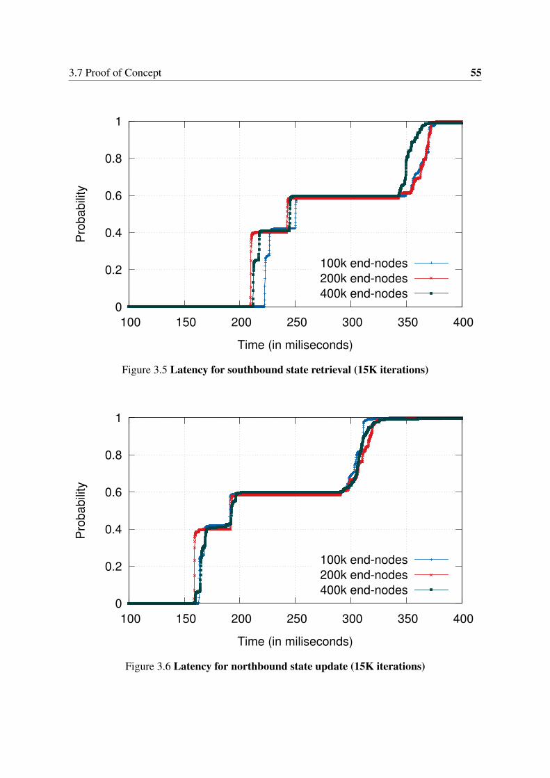
3.7 Proof of Concept 55
0
0.2
0.4
0.6
0.8
1
100 150 200 250 300 350 400
Pro
babi
lity
Time (in miliseconds)
100k end-nodes200k end-nodes400k end-nodes
Figure 3.5 Latency for southbound state retrieval (15K iterations)
0
0.2
0.4
0.6
0.8
1
100 150 200 250 300 350 400
Pro
babi
lity
Time (in miliseconds)
100k end-nodes200k end-nodes400k end-nodes
Figure 3.6 Latency for northbound state update (15K iterations)
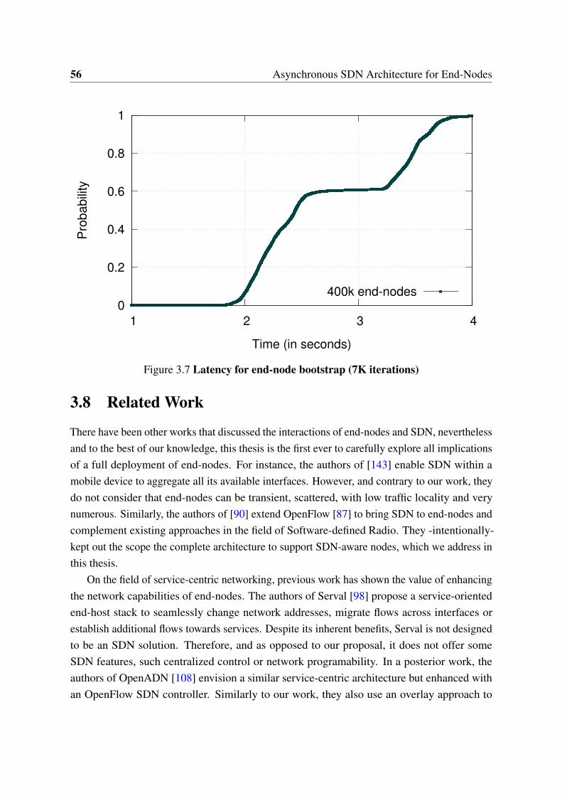
56 Asynchronous SDN Architecture for End-Nodes
0
0.2
0.4
0.6
0.8
1
1 2 3 4
Pro
babi
lity
Time (in seconds)
400k end-nodes
Figure 3.7 Latency for end-node bootstrap (7K iterations)
3.8 Related Work
There have been other works that discussed the interactions of end-nodes and SDN, neverthelessand to the best of our knowledge, this thesis is the first ever to carefully explore all implicationsof a full deployment of end-nodes. For instance, the authors of [143] enable SDN within amobile device to aggregate all its available interfaces. However, and contrary to our work, theydo not consider that end-nodes can be transient, scattered, with low traffic locality and verynumerous. Similarly, the authors of [90] extend OpenFlow [87] to bring SDN to end-nodes andcomplement existing approaches in the field of Software-defined Radio. They -intentionally-kept out the scope the complete architecture to support SDN-aware nodes, which we address inthis thesis.
On the field of service-centric networking, previous work has shown the value of enhancingthe network capabilities of end-nodes. The authors of Serval [98] propose a service-orientedend-host stack to seamlessly change network addresses, migrate flows across interfaces orestablish additional flows towards services. Despite its inherent benefits, Serval is not designedto be an SDN solution. Therefore, and as opposed to our proposal, it does not offer someSDN features, such centralized control or network programability. In a posterior work, theauthors of OpenADN [108] envision a similar service-centric architecture but enhanced withan OpenFlow SDN controller. Similarly to our work, they also use an overlay approach to
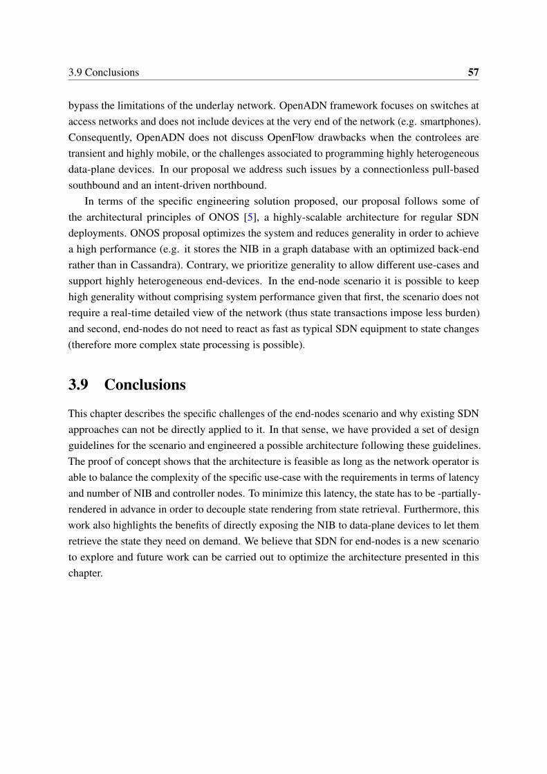
3.9 Conclusions 57
bypass the limitations of the underlay network. OpenADN framework focuses on switches ataccess networks and does not include devices at the very end of the network (e.g. smartphones).Consequently, OpenADN does not discuss OpenFlow drawbacks when the controlees aretransient and highly mobile, or the challenges associated to programming highly heterogeneousdata-plane devices. In our proposal we address such issues by a connectionless pull-basedsouthbound and an intent-driven northbound.
In terms of the specific engineering solution proposed, our proposal follows some ofthe architectural principles of ONOS [5], a highly-scalable architecture for regular SDNdeployments. ONOS proposal optimizes the system and reduces generality in order to achievea high performance (e.g. it stores the NIB in a graph database with an optimized back-endrather than in Cassandra). Contrary, we prioritize generality to allow different use-cases andsupport highly heterogeneous end-devices. In the end-node scenario it is possible to keephigh generality without comprising system performance given that first, the scenario does notrequire a real-time detailed view of the network (thus state transactions impose less burden)and second, end-nodes do not need to react as fast as typical SDN equipment to state changes(therefore more complex state processing is possible).
3.9 Conclusions
This chapter describes the specific challenges of the end-nodes scenario and why existing SDNapproaches can not be directly applied to it. In that sense, we have provided a set of designguidelines for the scenario and engineered a possible architecture following these guidelines.The proof of concept shows that the architecture is feasible as long as the network operator isable to balance the complexity of the specific use-case with the requirements in terms of latencyand number of NIB and controller nodes. To minimize this latency, the state has to be -partially-rendered in advance in order to decouple state rendering from state retrieval. Furthermore, thiswork also highlights the benefits of directly exposing the NIB to data-plane devices to let themretrieve the state they need on demand. We believe that SDN for end-nodes is a new scenarioto explore and future work can be carried out to optimize the architecture presented in thischapter.

Chapter 4
Decentralized SDN Architecture forOperators NFV
The Network Function Virtualization (NFV) paradigm is rapidly gaining interest among InternetService Providers (ISPs). However, the transition to this paradigm on ISP networks comes witha unique set of challenges, namely legacy equipment already in-place, heterogeneous trafficfrom multiple clients, and very large scalability requirements. In this chapter we thoroughlyanalyze such challenges and discuss NFV design guidelines that address them efficiently.Particularly, we show that a decentralization of the NFV control while maintaining globalstate improves scalability, offers better per-flow decisions and simplifies the implementation ofVirtual Network Functions (VNFs). Building on top of such principles, we propose a partiallydecentralized NFV architecture enabled via an enhanced decoupled-state SDN infrastructure.We also perform a qualitative analysis of the architecture to identify advantages and challenges.Finally, we determine the bottleneck component, based on the qualitative analysis, which weimplement and benchmark in order to assess the feasibility of the architecture.
4.1 Introduction
The Network Function Virtualization (NFV) paradigm enables software-hardware decoupling,flexible deployment of network functions and dynamic service provisioning [49]. Consequen-tially, it is raising special interest for Internet Service Providers (ISPs) since it will help reduceoperational costs and network complexity.
However, ISP networks are challenging due to its large size, the legacy networking hardwarealready in-place and the heterogeneous traffic generated by ISP’s customers. Therefore, anNFV architecture for ISPs must offer a platform able to scale to a wide range of different
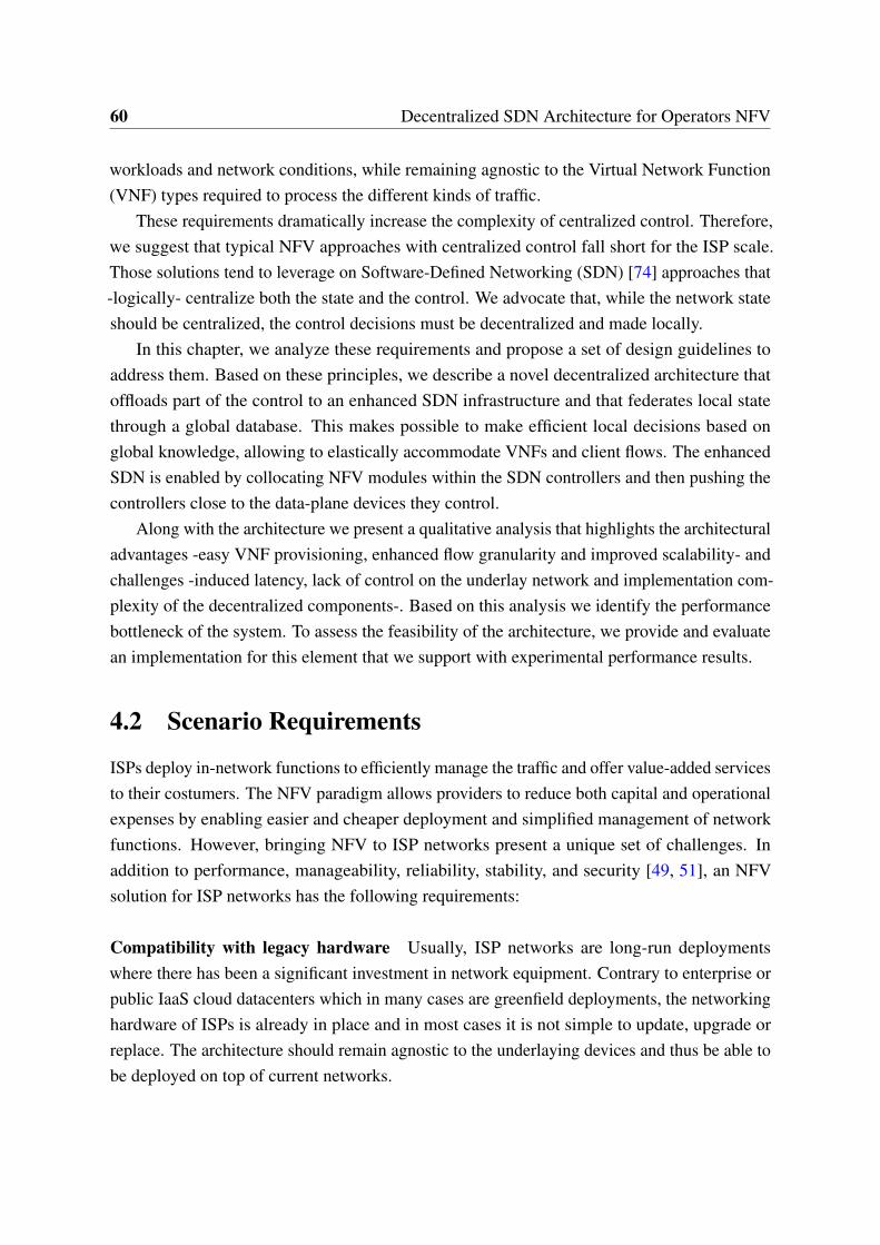
60 Decentralized SDN Architecture for Operators NFV
workloads and network conditions, while remaining agnostic to the Virtual Network Function(VNF) types required to process the different kinds of traffic.
These requirements dramatically increase the complexity of centralized control. Therefore,we suggest that typical NFV approaches with centralized control fall short for the ISP scale.Those solutions tend to leverage on Software-Defined Networking (SDN) [74] approaches that-logically- centralize both the state and the control. We advocate that, while the network stateshould be centralized, the control decisions must be decentralized and made locally.
In this chapter, we analyze these requirements and propose a set of design guidelines toaddress them. Based on these principles, we describe a novel decentralized architecture thatoffloads part of the control to an enhanced SDN infrastructure and that federates local statethrough a global database. This makes possible to make efficient local decisions based onglobal knowledge, allowing to elastically accommodate VNFs and client flows. The enhancedSDN is enabled by collocating NFV modules within the SDN controllers and then pushing thecontrollers close to the data-plane devices they control.
Along with the architecture we present a qualitative analysis that highlights the architecturaladvantages -easy VNF provisioning, enhanced flow granularity and improved scalability- andchallenges -induced latency, lack of control on the underlay network and implementation com-plexity of the decentralized components-. Based on this analysis we identify the performancebottleneck of the system. To assess the feasibility of the architecture, we provide and evaluatean implementation for this element that we support with experimental performance results.
4.2 Scenario Requirements
ISPs deploy in-network functions to efficiently manage the traffic and offer value-added servicesto their costumers. The NFV paradigm allows providers to reduce both capital and operationalexpenses by enabling easier and cheaper deployment and simplified management of networkfunctions. However, bringing NFV to ISP networks present a unique set of challenges. Inaddition to performance, manageability, reliability, stability, and security [49, 51], an NFVsolution for ISP networks has the following requirements:
Compatibility with legacy hardware Usually, ISP networks are long-run deploymentswhere there has been a significant investment in network equipment. Contrary to enterprise orpublic IaaS cloud datacenters which in many cases are greenfield deployments, the networkinghardware of ISPs is already in place and in most cases it is not simple to update, upgrade orreplace. The architecture should remain agnostic to the underlaying devices and thus be able tobe deployed on top of current networks.
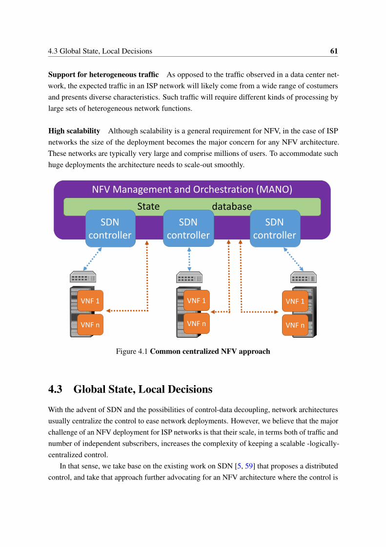
4.3 Global State, Local Decisions 61
Support for heterogeneous traffic As opposed to the traffic observed in a data center net-work, the expected traffic in an ISP network will likely come from a wide range of costumersand presents diverse characteristics. Such traffic will require different kinds of processing bylarge sets of heterogeneous network functions.
High scalability Although scalability is a general requirement for NFV, in the case of ISPnetworks the size of the deployment becomes the major concern for any NFV architecture.These networks are typically very large and comprise millions of users. To accommodate suchhuge deployments the architecture needs to scale-out smoothly.
VNF 1
VNF n
State database
VNF 1
VNF n
VNF 1
VNF n
NFV Management and Orchestration (MANO)
SDN controller
SDN controller
SDN controller
Figure 4.1 Common centralized NFV approach
4.3 Global State, Local Decisions
With the advent of SDN and the possibilities of control-data decoupling, network architecturesusually centralize the control to ease network deployments. However, we believe that the majorchallenge of an NFV deployment for ISP networks is that their scale, in terms both of traffic andnumber of independent subscribers, increases the complexity of keeping a scalable -logically-centralized control.
In that sense, we take base on the existing work on SDN [5, 59] that proposes a distributedcontrol, and take that approach further advocating for an NFV architecture where the control is
62 Decentralized SDN Architecture for Operators NFV
not only distributed but also partially decentralized. We seek to find a middle ground, betweenthe decentralization of legacy networks and the centralization brought by SDN, where thebenefits of both approaches can be combined and maximized.
We argue that this optimal balance can be achieved by enforcing local decisions whilekeeping global state. That is, federating the state generated locally to make the outcome ofthe local decisions globally available. As a result, the decision on how to act on a flow can bemade by the node that detects the flow, but taking into account the global state of the system atthat time. This approach is possible thanks to applying the principle of decoupling state fromcontrol proposed in this thesis.
4.4 Design Principles
In what follows we propose a set of design guidelines to achieve this partial decentralization aswell as to face the other requirements of the ISP scenario.
MANO disassembling We refer to the ETSI architectural framework [27] that defines theManagement and Orchestration (MANO) system as the central point for NFV control [28].The MANO system comprises the global orchestration of the architecture and the managementof the VNFs and the virtualized infrastructure. Albeit this system may be -and in most casesis- physically distributed, it remains as a logically centralized point of control as shown inFig. 4.1. We propose to keep centralized the service/functions catalogs and the general NFVorchestration, and partially the management of the virtual resources other than network (storage,computing), since this management is local per each datacenter but centralized within its locality.However, we advocate that the management of the virtual network can be completely offloadedto the infrastructure and totally decentralized and auto-coordinated thanks to an enhanced SDNinfrastructure. In a similar fashion, the VNF management can be also partially offloaded. Whilethe creation and destruction of VNF instances should be still coordinated by a centralized entity(e.g. OpenStack [106]), the monitoring, balancing and load assignment can be decentralizedand coordinated directly by the enhanced SDN infrastructure. In this chapter we use theterm MANO loosely and focus on the networking aspects of the system, i.e. the enhancedSDN-fabric. For the rest of the MANO components not discussed in detail we leverage on theexisting solutions.
SDN infrastructure enhancement To achieve an enhanced SDN infrastructure the differentinstances of the SDN controller (located at the MANO system and used to control the network)must be isolated and pushed close to the data-plane devices they control, effectively enabling a
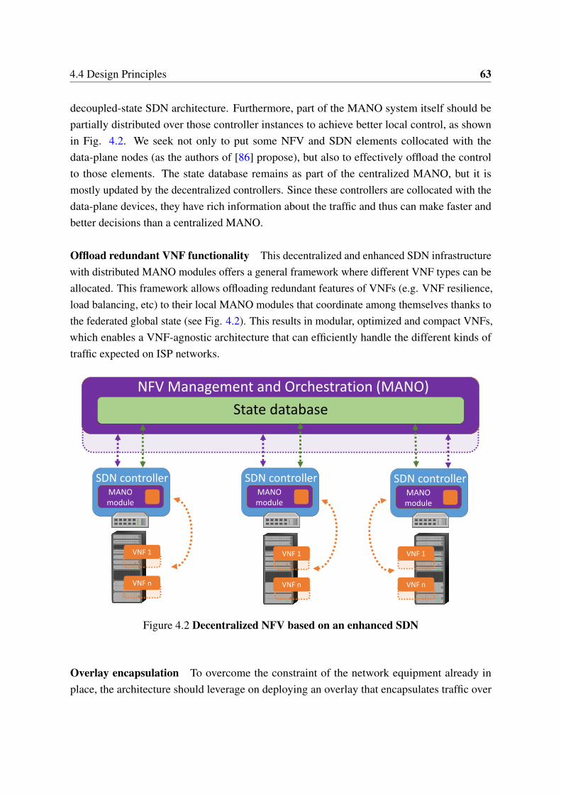
4.4 Design Principles 63
decoupled-state SDN architecture. Furthermore, part of the MANO system itself should bepartially distributed over those controller instances to achieve better local control, as shownin Fig. 4.2. We seek not only to put some NFV and SDN elements collocated with thedata-plane nodes (as the authors of [86] propose), but also to effectively offload the controlto those elements. The state database remains as part of the centralized MANO, but it ismostly updated by the decentralized controllers. Since these controllers are collocated with thedata-plane devices, they have rich information about the traffic and thus can make faster andbetter decisions than a centralized MANO.
Offload redundant VNF functionality This decentralized and enhanced SDN infrastructurewith distributed MANO modules offers a general framework where different VNF types can beallocated. This framework allows offloading redundant features of VNFs (e.g. VNF resilience,load balancing, etc) to their local MANO modules that coordinate among themselves thanks tothe federated global state (see Fig. 4.2). This results in modular, optimized and compact VNFs,which enables a VNF-agnostic architecture that can efficiently handle the different kinds oftraffic expected on ISP networks.
SDN controller
NFV Management and Orchestration (MANO)
State database
VNF 1
VNF n
VNF 1
VNF n
VNF 1
VNF n
MANOmodule
SDN controllerMANOmodule
SDN controllerMANOmodule
Figure 4.2 Decentralized NFV based on an enhanced SDN
Overlay encapsulation To overcome the constraint of the network equipment already inplace, the architecture should leverage on deploying an overlay that encapsulates traffic over
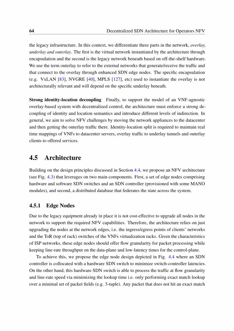
64 Decentralized SDN Architecture for Operators NFV
the legacy infrastructure. In this context, we differentiate three parts in the network, overlay,underlay and outerlay. The first is the virtual network instantiated by the architecture throughencapsulation and the second is the legacy network beneath based on off-the-shelf hardware.We use the term outerlay to refer to the external networks that generate/receive the traffic andthat connect to the overlay through enhanced SDN edge nodes. The specific encapsulation(e.g. VxLAN [83], NVGRE [40], MPLS [127], etc) used to instantiate the overlay is notarchitecturally relevant and will depend on the specific underlay beneath.
Strong identity-location decoupling Finally, to support the model of an VNF-agnosticoverlay-based system with decentralized control, the architecture must enforce a strong de-coupling of identity and location semantics and introduce different levels of indirection. Ingeneral, we aim to solve NFV challenges by moving the network appliances to the datacenterand then getting the outerlay traffic there. Identity-location split is required to maintain realtime mappings of VNFs to datacenter servers, overlay traffic to underlay tunnels and outerlayclients to offered services.
4.5 Architecture
Building on the design principles discussed in Section 4.4, we propose an NFV architecture(see Fig. 4.3) that leverages on two main components. First, a set of edge nodes comprisinghardware and software SDN switches and an SDN controller (provisioned with some MANOmodules), and second, a distributed database that federates the state across the system.
4.5.1 Edge Nodes
Due to the legacy equipment already in place it is not cost-effective to upgrade all nodes in thenetwork to support the required NFV capabilities. Therefore, the architecture relies on justupgrading the nodes at the network edges, i.e. the ingress/egress points of clients’ networksand the ToR (top of rack) switches of the VNFs virtualization racks. Given the characteristicsof ISP networks, these edge nodes should offer flow granularity for packet processing whilekeeping line-rate throughput on the data-plane and low-latency times for the control-plane.
To achieve this, we propose the edge node design depicted in Fig. 4.4 where an SDNcontroller is collocated with a hardware SDN switch to minimize switch-controller latencies.On the other hand, this hardware SDN switch is able to process the traffic at flow granularityand line-rate speed via minimizing the lookup time i.e. only performing exact match lookupover a minimal set of packet fields (e.g. 3-tuple). Any packet that does not hit an exact match
4.5 Architecture 65
entry (i.e. no rule available for its flow) is sent upwards to the control-plane through a softwareSDN switch. Although slower, the software SDN switch allows performing as granular flowlook-ups as required (e.g. coarse 5-tuple) and define as many rules as needed. The softwareSDN switch contains detailed rules to classify the flow according to a given profile and hand itto the appropriate MANO service module located within the SDN controller.
These MANO modules are per-service specific software pieces that can assign flows to VNFchains and program accordingly the hardware switch (see Section 4.5.4). Once the softwareswitch has classified the flow and handed it to the proper MANO module, the module willcheck if there is already cached an VNF chain suitable for the flow. If that is not the case, it usesthe controller’s database interface to retrieve a suitable chain from the federated information(see Section 4.5.2). If no suitable chain exists for that specific flow, the service module has tocompute one itself as described in Section 4.5.4. After retrieving/computing the VNF chain,the MANO service module uses the controller’s southbound interface to program (e.g. viaOpenFlow [87]) the exact match rules in the hardware switch. Subsequent packets of the flowwill hit the exact match entry and be processed at hardware level.
Global state database
Underlay
Subscribers Internet
VN
F 1
VN
F 2
VN
F 3
VN
F 4
Traffic classification
Traffic forwarding
State exchange
Encapsulatedtraffic
Traffic
MA
NO
Edgenode
MA
NO
Edgenode
Edgenode
MA
NO
Edgenode
MA
NO
NFV Management and Orchestration (MANO)
Figure 4.3 Proposed architecture
66 Decentralized SDN Architecture for Operators NFV
4.5.2 Federated Global State
A physically distributed, but logically centralized, database federates all the state generatedlocally at the edge nodes (e.g. computed VNF chains, etc) and makes it globally available tothe whole infrastructure. It also stores general MANO information (network services catalog,VNF catalog, VNF instances, infrastructure status, etc) [28] and in this sense is populated bothby the distributed MANO elements and by the centralized MANO subsystem. A summary ofthe information stored is provided below.
• VNF class → VNF instances: The abstract VNF classes that the different service use areinstantiated into (and mapped to) specific VNF instances.
• Flow → VNF chain: Each flow already processed is mapped to its assigned chain ofVNF instances.
• VNF instance → Instance status: Per each VNF instance the database stores i.e. itscurrent location, the number of flows assigned to it, its reachability, etc.
The database follows a strong location-identity decoupling model to store the informationwhich allows to easily introduce different levels of indirection. This entitles end-points tosmoothly move across different access networks and allows VNFs to be elastically allocatedboth inside and outside a datacenter. Following this model, the edge nodes have to registerin the global state their network location mapped to the subscribers they are serving, and theMANO system has to register the locations where it is allocating the VNFs.
For the database implementation, the architecture uses a DHT database back-end in order tooffer a scalable storage with a delimited query time. In terms of available solutions, Cassandra[75] can fulfill the requirements due to its good availability and excellent scale-out capacity[119]. For the front-end interface to the database, the architecture uses LISP [30, 126], a pull-based protocol that allows retrieving identity-to-location mappings from a central repository.LISP fits well the identity-location split model required by the architecture and offers aninteroperable (i.e. IETF-baked) and lightweight mechanism to retrieve state.
Given that the large size of the network leads to considerable state to store, to keep thearchitecture scalable the state is only pulled on demand by edge nodes. Therefore, in order tonotify changes and keep the state consistent the database follows a publish-subscribe mechanism[4]. As an example, if a VNF instance has to be moved to a different physical host, the edgenodes making use of the instance will be notified in order to allow them to encapsulate theflows towards the new location of the instance.
4.5 Architecture 67
4.5.3 Virtual Network Functions (VNFs)
The VNFs are allocated in generic virtualization racks with an edge node as ToR switch.Due to the encapsulation and the location-identity split, the VNFs can be dynamically movedacross hosts, racks or datacenters. Therefore, the model allows to both encapsulate the traffictowards where the VNFs are and/or move the VNFs close to where the traffic is. All this pathcomputation complexity is offloaded to the MANO service modules at the edge nodes.
In this architecture, the VNFs are unaware of the rest of the system (i.e. they do not knowthe next hop for a flow) therefore the scope of the VNF state is restricted to flow processing.The fact that the VNFs are unaware of each other simplifies their elastic allocation and thedeployment of new services, since different VNFs from different services can be easily chained.
The architecture keeps VNFs as simple as possible. Ideally each VNF should do only onesingle task. The idea is to be able to create complex services by chaining several VNFs whilemaintaining a flexible system that can scale-out in a modular fashion. That is, if a VNF isexperiencing high load, that specific VNF can be scaled-out independently without affectingother VNFs in the chain.
In this sense, the architecture trims out redundant logic common to all VNFs and movesit to the distributed MANO modules. Scalability, load balancing, high availability, etc, aredecoupled from the VNFs and offloaded to the infrastructure. For instance, a VNF processespackets unaware of any balancing policies and it is its local MANO module that monitors theload and takes care of tuning the general system to properly balance flows among differentVNFs.
The combination of an architecture that is VNF-agnostic and of VNFs that are simple, lightand interoperable, enables VNF outsourcing. The VNFs do not need to be specifically developedfor the particular NFV system but rather can be developed by third parties and smoothlyintegrated with other VNFs. The architecture eases the development of such outsourced VNFs,since VNF-vendors can leverage on the mechanisms offered by the infrastructure and thusavoid dealing with ISP networks scalability or availability requirements.
4.5.4 Management and orchestration (MANO)
The architecture leverages on a service-based model where the centralized MANO installsdistributed service-specific modules in the edge node controllers, and programs the softwareSDN switches to redirect service-specific traffic to the proper MANO module. Services use thecentralized MANO subsystem to create the VNFs, but through these distributed modules, eachservice defines the traffic to be processed by the service, the VNF classes that should process
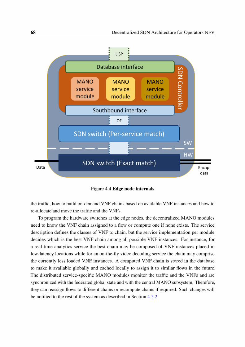
68 Decentralized SDN Architecture for Operators NFV
MANOservicemodule
MANOservicemodule
MANOservicemodule
SDN switch (Per-service match)
Southbound interface
OF
Database interface
LISP
SW
HW
SDN
Co
ntro
ller
SDN switch (Exact match)Data Encap.
data
Figure 4.4 Edge node internals
the traffic, how to build on-demand VNF chains based on available VNF instances and how tore-allocate and move the traffic and the VNFs.
To program the hardware switches at the edge nodes, the decentralized MANO modulesneed to know the VNF chain assigned to a flow or compute one if none exists. The servicedescription defines the classes of VNF to chain, but the service implementation per moduledecides which is the best VNF chain among all possible VNF instances. For instance, fora real-time analytics service the best chain may be composed of VNF instances placed inlow-latency locations while for an on-the-fly video decoding service the chain may comprisethe currently less loaded VNF instances. A computed VNF chain is stored in the databaseto make it available globally and cached locally to assign it to similar flows in the future.The distributed service-specific MANO modules monitor the traffic and the VNFs and aresynchronized with the federated global state and with the central MANO subsystem. Therefore,they can reassign flows to different chains or recompute chains if required. Such changes willbe notified to the rest of the system as described in Section 4.5.2.
4.6 Qualitative Analysis 69
4.6 Qualitative Analysis
The proposed architecture results in a set of qualitative advantages and technical challengesthat we analyze in this section.
4.6.1 Advantages
Decentralization boosts scale-out
Since the coordination required among the different parts of the architecture is relaxed, it iseasier for these parts to scale-out independently. This can be achieved for the architecture as awhole (e.g. adding more edge nodes) or for each component individually (e.g. adding morephysical servers to an edge node cluster).
Flow granularity even at large networks
The optimized flow lookup allows for more flows to be handled per each hardware switch andthus reduces the cost of scaling-out the edge nodes to allocate more traffic. In general, allarchitecture components are designed to keep flow granularity despite the network size. Edgenodes process flows in parallel independently, VNFs keep only per-flow state and the federateddatabase uses a plain namespace with constant access time.
Better per-flow decisions
The decisions on how to process a flow are taken close to the data-plane devices carrying theflow itself. Therefore, more and richer per-flow information is available. The flow granular-ity processing and this detailed per-flow information entitle for complex per-flow decisions,something that is challenging to accomplish with traditional logically centralized architectures.
Simpler VNFs and VNF outsourcing
Offloading redundant network functions features to the enhanced SDN infrastructure enables toreduce VNF complexity. This combined with the VNF agnosticism enabled by the architectureoffers the possibility of outsourcing the VNF development to third parties.
70 Decentralized SDN Architecture for Operators NFV
4.6.2 Challenges
Global state query latency
The architecture forces edge nodes to retrieve state from the global database (e.g. to checkif there is already a VNF chain associate to a flow) and to keep this state updated. Althoughstate queries are done in parallel (i.e. they do not affect architecture’s scale-out properties),the architecture needs to ensure that this state retrieval is fast enough in order to avoid being aburden for the system performance.
However, technologies already available should offer low enough query time. In particular,the read operation of a Cassandra (or equivalent) DHT database will add no more than a fewmilliseconds even under high loads [119] and an optical underlying transport connecting theedge nodes to the database will only induce latency in the order of microseconds [64].
Lack of control for the underlay network
The architecture uses the underlay network and has to rely on its correct operation. If that isnot the case the architecture has no control over it and is unable to fix the problem.
However, ISP networks will likely have their own troubleshooting and healing mechanisms,as assumed in [59], and be reliable enough to allow the correct operation of the architecture.Even though, in the case of a major connectivity problem, the enhanced SDN infrastructure maybe able to transparently redirect the traffic to a reachable point thanks to the identity-locationsplit schema enforced.
Edge node implementation
The proposed service-based decentralization presents a particular challenge at the edge nodessince it requires complex classifying and forwarding mechanisms that need to remain scalable.
For the embedded controller, each MANO module is independent of the others and itsperformance is not affected by the number or complexity of other modules and thereforescale-out requirements can be met with a cluster-friendly controller (e.g. OpenDaylight [103])able to distribute the load. On the other hand, the hardware switch is agnostic to the servicecomplexity or its number since it only considers independent exact match rules, and thus it canbe scaled-out across several hardware devices.
The bottleneck of the system is the software switch. In this case, contrary to the rulesallocated in the hardware switch, the rules required to support more services or more complexones comprise wildcarded fields, longest prefix match lookups and different priorities (sincethese rules will likely overlap). This makes the complexity of flow classification at the software
4.7 Software Switch Implementation 71
switch to increase non-linearly with respect to the complexity or number of services. As a result,the architecture needs a software switch capable of achieving the linear scalability requiredby the large number of flows expected, despite the non-linear complexity faced in the flowclassification. This makes the software switch the greatest challenge of the architecture.
4.7 Software Switch Implementation
From the analysis on Section 4.6, we conclude that the scalability on the system will be cappedout by the performance achieved by the software switch. In the related research literature itis possible to find different performance evaluations for software switches reporting differentresults [114, 145, 23, 111]. To asses the feasibility of the architecture, in this section we discussthe software switch implementation.
We measured the performance of currently available software switches, particularly OpenvSwitch [111], and we were able to achieve 11M packets per second (pps) using OVS 2.3.1(DPDK-optimized [58]) on a single core with 100 OpenFlow rules and less than 100 trafficflows. This number is similar to the one reported in [23] and, at the best of our knowledge, thisis due to caching lookup results for known flows to effectively bypassing the OpenFlow lookuptables. When we raised the number of flows to 500K, a number closer to the ISP scenario,the performance dropped to 300K pps. We observed also non-linear scaling since a 8-coreconfiguration only achieved 1.2M pps. The hardware used for these tests was similar to the onedescribed latter in this section.
To achieve ISP performance requirements we implemented our own in-house softwareswitch, written in C and leveraging on DPDK. It is based in a multithreaded design where allthreads have access to the rules from a common memory space. Each thread handles a subsetof the flows distributed to it based on 5-tuple hashing performed by the NICs, using ReceiveSide Scaling (RSS) technology with a queue per thread. The OpenFlow tables are presentedas static tables and updates are performed on a shadow copy of those tables. Periodicallythe shadow copy is switched with the active table set, updated with the changes made on theshadow copy and from there updates commence on the new shadow. The key to the highperformance implementation is that for every packet, the relevant rules are fetched into cachememory just in time for lookup. By pipelining the rule prefetching (i.e. handling a few packetsin parallel by each thread) the throughput is achieved by effectively always referencing rulesthat reside in the CPU cache (and not in off-chip memory). As a result, the performance isalmost independent of the number of rules.
To measure the scalability of the proposed software switch we performed the followingbenchmark. We ran the switch on an Intel-based server with dual Intel Xeon E5-2690 2.9GHz
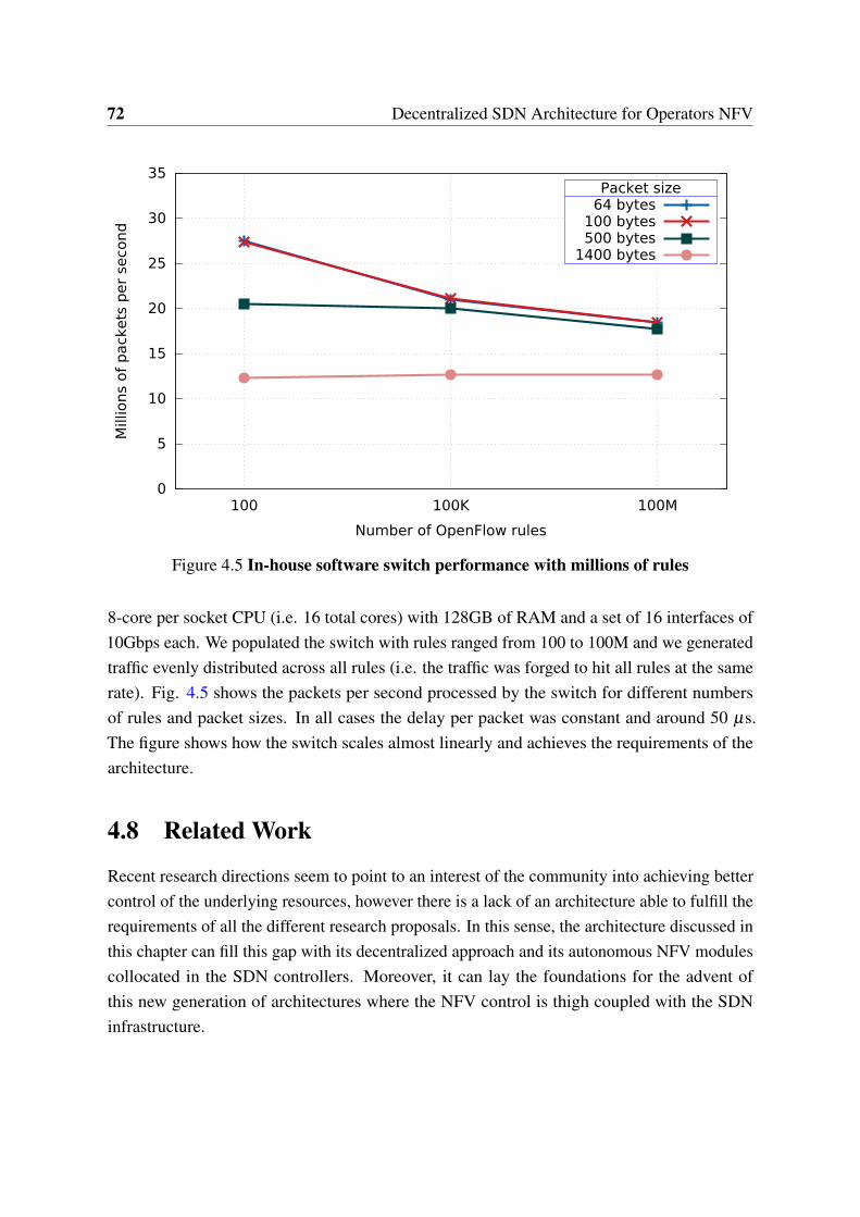
72 Decentralized SDN Architecture for Operators NFV
0
5
10
15
20
25
30
35
100 100K 100M
Mill
ions
of
pack
ets
per
seco
nd
Number of OpenFlow rules
Packet size64 bytes
100 bytes500 bytes
1400 bytes
Figure 4.5 In-house software switch performance with millions of rules
8-core per socket CPU (i.e. 16 total cores) with 128GB of RAM and a set of 16 interfaces of10Gbps each. We populated the switch with rules ranged from 100 to 100M and we generatedtraffic evenly distributed across all rules (i.e. the traffic was forged to hit all rules at the samerate). Fig. 4.5 shows the packets per second processed by the switch for different numbersof rules and packet sizes. In all cases the delay per packet was constant and around 50 µs.The figure shows how the switch scales almost linearly and achieves the requirements of thearchitecture.
4.8 Related Work
Recent research directions seem to point to an interest of the community into achieving bettercontrol of the underlying resources, however there is a lack of an architecture able to fulfill therequirements of all the different research proposals. In this sense, the architecture discussed inthis chapter can fill this gap with its decentralized approach and its autonomous NFV modulescollocated in the SDN controllers. Moreover, it can lay the foundations for the advent ofthis new generation of architectures where the NFV control is thigh coupled with the SDNinfrastructure.
4.9 Conclusions 73
An early example on how to enhance SDN data-plane devices by pushing some control tothem can be found in the work of Risso et al. [121]. The same authors later proposed in [14]an extended framework where they describe a dynamic NFV architecture targeting operatornetworks. In our work we move forward on that direction by collocating all the SDN controlwith the data-plane elements.
One example of such research is the work by Gember-Jacobson et al. [42] where they designan API to allow network functions to coordinate among themselves in an NFV-SDN scenario tooffer better packet processing. The decentralized MANO modules of the presented architecturecan intercommunicate with API-enabled network functions and thus enable enhanced flowprocessing.
Another example of this research trend is the work of Matias et al. [86] that propose toleverage on the SDN capabilities of the network to directly implement some VNFs withoutthe need of allocating a VM with the VNF. For instance they argue that a firewall can beimplemented by means of OpenFlow rules installed in the networking devices that drop (orallow) packet belonging to target flows. This proposal can use the architecture presented in thischapter to efficiently program the edge node switches to implement SDN-based VNFs.
Beyond academic initiatives, industry-driven projects like Telefonica’s OpenMANO [105]also shows an interest in modifying existing NFV solutions to, among other goals, achievea closer control of the network fabric. To that end, they modify OpenStack to better controla networking infrastructure based on Intel’s DPDK. The architecture that we propose cansimilarly program a DPDK data-plane in the same way it programs the edge node hardwareswitches.
4.9 Conclusions
The architecture presented in this chapter aims to address the scalability concerns of large ISPnetworks via partially decentralizing the MANO system. Contrary to most NFV proposals, theSDN controllers used by the MANO are collocated with their controlees and provisioned withNFV modules. This enables faster local processing by means of reducing centralization. Ingeneral the architecture seeks to find a good tradeoff of complexity, performance and scalabilityby decentralizing some components while keeping a centralized state. This results in a set ofbenefits for NFV deployments on ISP networks such as, enhanced scale-out capacity, flowgranularity decisions and optimized VNFs. However, these benefits come at the cost of someassociated challenges, particularly the egde node complexity introduced by the decentralization.We identified the software switch needed for flow classification at the edge nodes as the

74 Decentralized SDN Architecture for Operators NFV
bottleneck of the system and proposed a switch implementation able to fulfill the performancerequirements of ISP networks.
Part II
Deploying SDN for End-Nodes

Chapter 5
Privacy for LISP Mobile Nodes
LISP offers native mobility by decoupling IP addresses semantics into Endpoint Identifiers(EIDs) and Routing Locators (RLOCs). LISP Mobile Node (LISP-MN) is the particular case ofLISP that specifies mobility. Supporting LISP-MN is a key point to enable SDN for end-nodesin the way described in Chapter 3. However, mobility protocols have an inherent issue withprivacy since some users may not want to reveal their location or their identity. In this aspect,LISP-MN is no different from other mobility protocols and thus privacy issues should beconsidered to effective deploy an infrastructure relaying in LISP-MN. In this chapter, we reviewLISP-MN and its privacy concerns and propose solutions to enable privacy, both in terms oflocation and identity.
5.1 Introduction
In the LISP architecture, EIDs identify hosts and are assigned independently of the networktopology while RLOCs identify network attachment points and are used for routing. LISPdesign allows EIDs to remain unchanged even if a topological change (such as a handover)occurs. This makes the protocol well suited for mobility [125, 39]. Indeed, the mobility versionof the LISP protocol (LISP-MN [32, 125]) proposes LISP-enabled endpoints, which enableslegacy applications to smoothly roam across access technologies and service providers. TheLISP-MN protocol uses the Mapping System [38] to disseminate the EID-to-RLOC bindings.
Since mobility protocols typically use addresses to locate users, they raise privacy concerns,and in this context LISP-MN is not an exception. An attacker could learn the (approximate)physical location of a user by monitoring its locator address, for instance by using IP geograph-ical localization techniques [142]. This issue is exacerbated in LISP-MN when compared toother mobility protocols, such as Mobile IP [109, 63]. In Mobile IP an attacker has to establisha connection with the mobile node to learn its location, this way a mobile node can reject
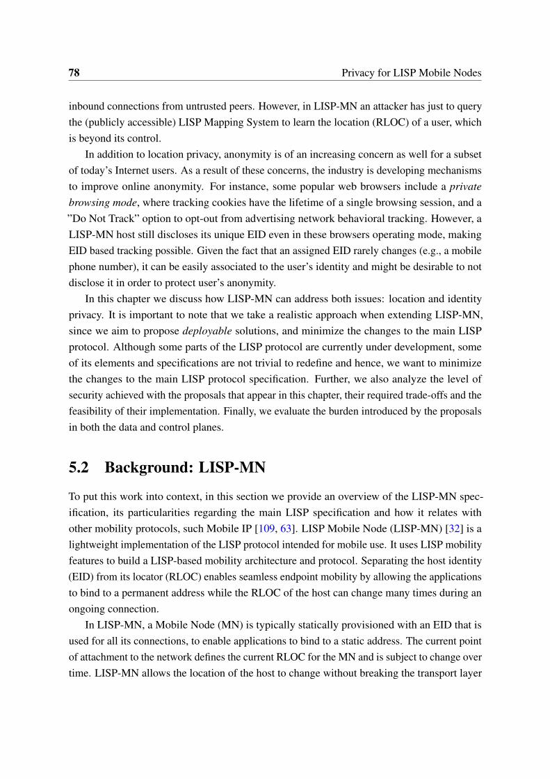
78 Privacy for LISP Mobile Nodes
inbound connections from untrusted peers. However, in LISP-MN an attacker has just to querythe (publicly accessible) LISP Mapping System to learn the location (RLOC) of a user, whichis beyond its control.
In addition to location privacy, anonymity is of an increasing concern as well for a subsetof today’s Internet users. As a result of these concerns, the industry is developing mechanismsto improve online anonymity. For instance, some popular web browsers include a privatebrowsing mode, where tracking cookies have the lifetime of a single browsing session, and a”Do Not Track” option to opt-out from advertising network behavioral tracking. However, aLISP-MN host still discloses its unique EID even in these browsers operating mode, makingEID based tracking possible. Given the fact that an assigned EID rarely changes (e.g., a mobilephone number), it can be easily associated to the user’s identity and might be desirable to notdisclose it in order to protect user’s anonymity.
In this chapter we discuss how LISP-MN can address both issues: location and identityprivacy. It is important to note that we take a realistic approach when extending LISP-MN,since we aim to propose deployable solutions, and minimize the changes to the main LISPprotocol. Although some parts of the LISP protocol are currently under development, someof its elements and specifications are not trivial to redefine and hence, we want to minimizethe changes to the main LISP protocol specification. Further, we also analyze the level ofsecurity achieved with the proposals that appear in this chapter, their required trade-offs and thefeasibility of their implementation. Finally, we evaluate the burden introduced by the proposalsin both the data and control planes.
5.2 Background: LISP-MN
To put this work into context, in this section we provide an overview of the LISP-MN spec-ification, its particularities regarding the main LISP specification and how it relates withother mobility protocols, such Mobile IP [109, 63]. LISP Mobile Node (LISP-MN) [32] is alightweight implementation of the LISP protocol intended for mobile use. It uses LISP mobilityfeatures to build a LISP-based mobility architecture and protocol. Separating the host identity(EID) from its locator (RLOC) enables seamless endpoint mobility by allowing the applicationsto bind to a permanent address while the RLOC of the host can change many times during anongoing connection.
In LISP-MN, a Mobile Node (MN) is typically statically provisioned with an EID that isused for all its connections, to enable applications to bind to a static address. The current pointof attachment to the network defines the current RLOC for the MN and is subject to change overtime. LISP-MN allows the location of the host to change without breaking the transport layer
5.2 Background: LISP-MN 79
connection. This is possible since the MN implements a lightweight LISP tunnel router thatperforms mapping resolution and encapsulation operations directly on the MN. Packets - exceptfor management protocols such as DHCP - are LISP encapsulated by the lightweight LISPtunnel at the mobile node, and routed based on the RLOCs to the destination site. The mobilenode tunnel routers remove also the LISP header from incoming packets before sending themto upper layers to ultimately reaching the destination application. In the event of a handover(e.g. when the location of the MN changes), the MN receives a new RLOC from the networkand it updates its EID-to-RLOC bindings at the Mapping-System to maintain reachability at itsnew location. Thanks to those updated bindings, other LISP tunnel routers can learn the newRLOC of the MN. More details and discussion of LISP-MN can be found in [32, 125, 91].
Fig. 5.1 summarizes the basic operation of LISP-MN. In the figure, the MN wants tocommunicate with its peer, from which only knows its EID. It sends (1) a Map-Request (MRq)to obtain the RLOC of the peer. This MRq is routed (2) through the Mapping System to finallyreach (3) the Tunnel Router (xTR) of the LISP site where the peer is. The xTR replies (4) tothe MN with its RLOC in a Map-Reply message (MRp). Finally, the MN sends (5) the data tothe xTR which forwards (6) it to the peer.
xTR
RLOC space
Mapping System
MRq:EID_B?
MNEID_A
PeerEID_B
DataData
MRq:EID_B?
MRq:EID_B?
MRp:EID_B-RLOC_2
LISP site
RLOC_2RLOC_1
1
2
3
4
56
Figure 5.1 LISP-MN Overview
80 Privacy for LISP Mobile Nodes
5.2.1 LISP-MN specifics
There are a few LISP specific aspects that need to be carefully considered in the LISP-MNmobility scenario. On one hand, the handover process (e.g. switch network access point) for aLISP-MN provisioned mobile node happens as follows. When a MN changes its attachment itregains connectivity in a new subnetwork. It first obtains a new RLOC and notifies the newEID-to-RLOC binding to its Map-Server. The MN has to update also all the bindings storedin the Map-Cache of the peers, either LISP routers or nodes, with which it is communicating.In order to do it uses the special signaling message called Solicit-Map-Request (SMR). Thereception of such message triggers a Map-Request to refresh the binding, it is important to notethat such message is transmitted over the Mapping-System, and hence prevents the double-jumpproblem (i.e. two MNs changing location at the same time). Overall, the handover latency inLISP is 1.5 Round Trip Times. Research efforts to optimize such handover latency are alreadyunder development and take base on LISP-SEC [84].
On the other hand, in the case of a LISP-MN mobile node behind a LISP site, doubleencapsulation is required. The RLOC of the MN is in fact an EID assigned by the xTRin charge of the LISP site. We refer to this EID as Location EID and to the permanentlyassigned MN’s EID as Permanent EID. In this scenario, when the MN roams into a LISP site,the xTR assigns (by means of DHCP) the location EID. The MN registers this EID into theMapping-System as its RLOC. The peer that wants to communicate with the MN queries theMapping-System and receives the Location EID as the RLOC of the MN. The peer will thenrealize that the Location EID is not routable and will consequently query again the Mapping-System to obtain the RLOC, this is the IP address assigned to the xTR where the MN is attached.At this point the peer (typically an xTR, or another MN) will then double encapsulate thepackets towards the MN. Upon reception, these packets will be first decapsulated by the xTR,and then by the MN.
5.2.2 LISP-MN vs. Mobile IP
Leveraging on LISP’s locator-identity decoupling, LISP-MN is a fully featured mobilityprotocol that supports both IPv4 and IPv6, network mobility, route optimization and nativemultihoming. Compared to other identity-location split schemes, LISP has a unique positionsince it is incrementally deployable and it does not require changes to transport/applicationimplementations. This makes LISP-MN a real alternative to provide mobility to the Internet.
During the last decade we have witnessed huge progress in wireless access technologies.This has lead to an increase in the adoption of mobile devices and demand for mobile Internet.Consequently, a plethora of solutions and protocols have been proposed (see [22] and the
5.2 Background: LISP-MN 81
references therein). Arguably, the most popular is the Mobile IP [109, 63] family of protocols.LISP-MN has a set of features with respect to Mobile IP that makes it an interesting alternative.In the following we detail the main reasons that support such statement:
• The Mobile IP family of protocols is a set of protocols that provides basic and advancedfunctionalities to mobile nodes. For instance there are two separate versions for IPv4[109] and IPv6 [63], and additional protocols for network (prefix) mobility. Furthermore,advanced features such as fast handovers [69] or multihoming [137] are again defined inseparate specifications. As a result, a developer willing to adopt Mobile IP must readand implement different protocols defined in several specifications. In LISP-MN all thefeatures are defined in a single protocol, and thus only require a single implementation.Currently LISP-MN supports IPv4, IPv6, network mobility and multihoming natively.The benefits of the native multihoming of LISP are inhered by LISP-MN: each EID prefixcan be mapped to more than one RLOC, and each RLOC can be assigned specific priorityand weight. This simplifies adoption and reduces significantly capital expenditure costs.
• LISP-MN separates the control plane functionality from the data plane, allowing each toscale independently. Since LISP-MN does not require Home Agent or Foreign Agentnetwork elements in the data plane, it avoids triangle routing at the data plane level, forboth IPv4 and IPv6 address families, along with network mobility data packets alwaysfollow the shortest path and hence, in this context LISP-MN incorporates native routeoptimization support. It is worth to note that when communicating with non-LISP sites,communications must be forwarded through a proxy.
• Separation of control plane from data plane in LISP-MN facilitates the decoupling ofend-point identity from the mobility service provider. The sole functionality of thecontrol plane is to locate a mobile node, much like DNS locating a service or a host nametoday. Similar to DNS, LISP control plane has a distributed and federated Mapping-System. Mobility becomes a native feature of the network architecture and avoidsmobility provider lock-in. In this context, LISP-MNs can change their RLOC provider-typically an Internet Service Provider (ISP)- and are tied to their EID provider, howeverand unlike in Mobile IP, such EID provider may not be an ISP (i.e, the home of themobile node) but rather a third-party company. EID providers do not operate in the dataplane as Home Address providers in Mobile IP, but in the control plane, and representnew business opportunities.
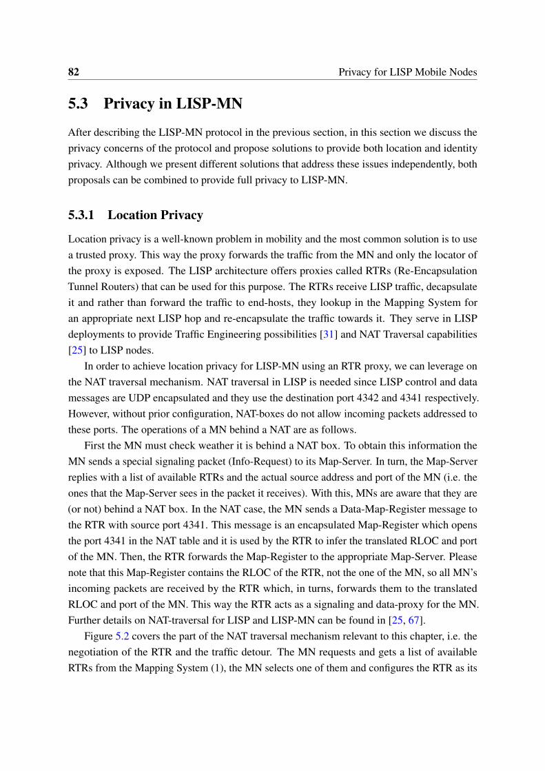
82 Privacy for LISP Mobile Nodes
5.3 Privacy in LISP-MN
After describing the LISP-MN protocol in the previous section, in this section we discuss theprivacy concerns of the protocol and propose solutions to provide both location and identityprivacy. Although we present different solutions that address these issues independently, bothproposals can be combined to provide full privacy to LISP-MN.
5.3.1 Location Privacy
Location privacy is a well-known problem in mobility and the most common solution is to usea trusted proxy. This way the proxy forwards the traffic from the MN and only the locator ofthe proxy is exposed. The LISP architecture offers proxies called RTRs (Re-EncapsulationTunnel Routers) that can be used for this purpose. The RTRs receive LISP traffic, decapsulateit and rather than forward the traffic to end-hosts, they lookup in the Mapping System foran appropriate next LISP hop and re-encapsulate the traffic towards it. They serve in LISPdeployments to provide Traffic Engineering possibilities [31] and NAT Traversal capabilities[25] to LISP nodes.
In order to achieve location privacy for LISP-MN using an RTR proxy, we can leverage onthe NAT traversal mechanism. NAT traversal in LISP is needed since LISP control and datamessages are UDP encapsulated and they use the destination port 4342 and 4341 respectively.However, without prior configuration, NAT-boxes do not allow incoming packets addressed tothese ports. The operations of a MN behind a NAT are as follows.
First the MN must check weather it is behind a NAT box. To obtain this information theMN sends a special signaling packet (Info-Request) to its Map-Server. In turn, the Map-Serverreplies with a list of available RTRs and the actual source address and port of the MN (i.e. theones that the Map-Server sees in the packet it receives). With this, MNs are aware that they are(or not) behind a NAT box. In the NAT case, the MN sends a Data-Map-Register message tothe RTR with source port 4341. This message is an encapsulated Map-Register which opensthe port 4341 in the NAT table and it is used by the RTR to infer the translated RLOC and portof the MN. Then, the RTR forwards the Map-Register to the appropriate Map-Server. Pleasenote that this Map-Register contains the RLOC of the RTR, not the one of the MN, so all MN’sincoming packets are received by the RTR which, in turns, forwards them to the translatedRLOC and port of the MN. This way the RTR acts as a signaling and data-proxy for the MN.Further details on NAT-traversal for LISP and LISP-MN can be found in [25, 67].
Figure 5.2 covers the part of the NAT traversal mechanism relevant to this chapter, i.e. thenegotiation of the RTR and the traffic detour. The MN requests and gets a list of availableRTRs from the Mapping System (1), the MN selects one of them and configures the RTR as its
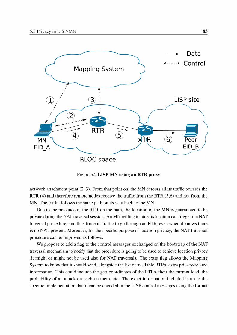
5.3 Privacy in LISP-MN 83
xTR
RLOC space
RTRMN
EID_APeer
EID_B
LISP site
4 6
1 3
5
Data
Mapping System
2
Control
Figure 5.2 LISP-MN using an RTR proxy
network attachment point (2, 3). From that point on, the MN detours all its traffic towards theRTR (4) and therefore remote nodes receive the traffic from the RTR (5,6) and not from theMN. The traffic follows the same path on its way back to the MN.
Due to the presence of the RTR on the path, the location of the MN is guaranteed to beprivate during the NAT traversal session. An MN willing to hide its location can trigger the NATtraversal procedure, and thus force its traffic to go through an RTR, even when it knows thereis no NAT present. Moreover, for the specific purpose of location privacy, the NAT traversalprocedure can be improved as follows.
We propose to add a flag to the control messages exchanged on the bootstrap of the NATtraversal mechanism to notify that the procedure is going to be used to achieve location privacy(it might or might not be used also for NAT traversal). The extra flag allows the MappingSystem to know that it should send, alongside the list of available RTRs, extra privacy-relatedinformation. This could include the geo-coordinates of the RTRs, their the current load, theprobability of an attack on each on them, etc. The exact information included is up to thespecific implementation, but it can be encoded in the LISP control messages using the format
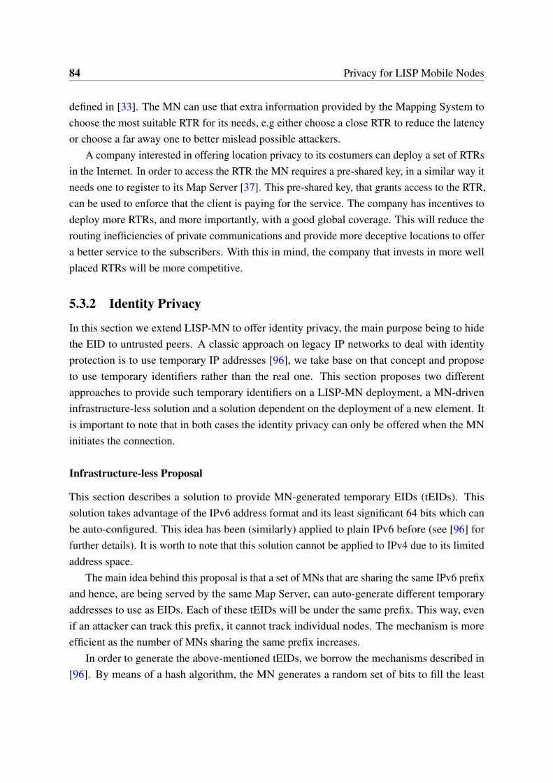
84 Privacy for LISP Mobile Nodes
defined in [33]. The MN can use that extra information provided by the Mapping System tochoose the most suitable RTR for its needs, e.g either choose a close RTR to reduce the latencyor choose a far away one to better mislead possible attackers.
A company interested in offering location privacy to its costumers can deploy a set of RTRsin the Internet. In order to access the RTR the MN requires a pre-shared key, in a similar way itneeds one to register to its Map Server [37]. This pre-shared key, that grants access to the RTR,can be used to enforce that the client is paying for the service. The company has incentives todeploy more RTRs, and more importantly, with a good global coverage. This will reduce therouting inefficiencies of private communications and provide more deceptive locations to offera better service to the subscribers. With this in mind, the company that invests in more wellplaced RTRs will be more competitive.
5.3.2 Identity Privacy
In this section we extend LISP-MN to offer identity privacy, the main purpose being to hidethe EID to untrusted peers. A classic approach on legacy IP networks to deal with identityprotection is to use temporary IP addresses [96], we take base on that concept and proposeto use temporary identifiers rather than the real one. This section proposes two differentapproaches to provide such temporary identifiers on a LISP-MN deployment, a MN-driveninfrastructure-less solution and a solution dependent on the deployment of a new element. Itis important to note that in both cases the identity privacy can only be offered when the MNinitiates the connection.
Infrastructure-less Proposal
This section describes a solution to provide MN-generated temporary EIDs (tEIDs). Thissolution takes advantage of the IPv6 address format and its least significant 64 bits which canbe auto-configured. This idea has been (similarly) applied to plain IPv6 before (see [96] forfurther details). It is worth to note that this solution cannot be applied to IPv4 due to its limitedaddress space.
The main idea behind this proposal is that a set of MNs that are sharing the same IPv6 prefixand hence, are being served by the same Map Server, can auto-generate different temporaryaddresses to use as EIDs. Each of these tEIDs will be under the same prefix. This way, evenif an attacker can track this prefix, it cannot track individual nodes. The mechanism is moreefficient as the number of MNs sharing the same prefix increases.
In order to generate the above-mentioned tEIDs, we borrow the mechanisms described in[96]. By means of a hash algorithm, the MN generates a random set of bits to fill the least
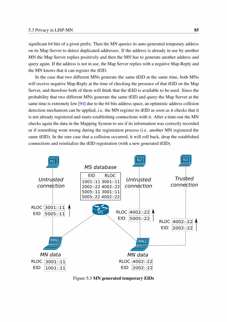
5.3 Privacy in LISP-MN 85
significant 64 bits of a given prefix. Then the MN queries its auto-generated temporary addresson its Map Server to detect duplicated addresses. If the address is already in use by anotherMN the Map Server replies positively and then the MN has to generate another address andquery again. If the address is not in use, the Map Server replies with a negative Map-Reply andthe MN knows that it can register the tEID.
In the case that two different MNs generate the same tEID at the same time, both MNswill receive negative Map-Reply at the time of checking the presence of that tEID on the MapServer, and therefore both of them will think that the tEID is available to be used. Since theprobability that two different MNs generate the same tEID and query the Map Server at thesame time is extremely low [94] due to the 64 bits address space, an optimistic address collisiondetection mechanism can be applied, i.e. the MN register its tEID as soon as it checks that itis not already registered and starts establishing connections with it. After a time-out the MNchecks again the data in the Mapping System to see if its information was correctly recordedor if something went wrong during the registration process (i.e. another MN registered thesame tEID). In the rare case that a collision occurred, it will roll back, drop the establishedconnections and reinitialize the tEID registration (with a new generated tEID).
MN1 MN2
MS
N1 N2 N3
4002::22
2002::22EID
RLOC
Trusted connection
3001::11
5005::11EID
RLOC
EID RLOC
1001::11 3001::112002::22 4002::225005::11 3001::115005::22 4002::22
4002::22
5005::22EID
RLOC
3001::11
1001::11EID
RLOC 4002::22
2002::22EID
RLOC
MN data MN data
Untrusted connection
Untrusted connection
MS database
Figure 5.3 MN generated temporary EIDs
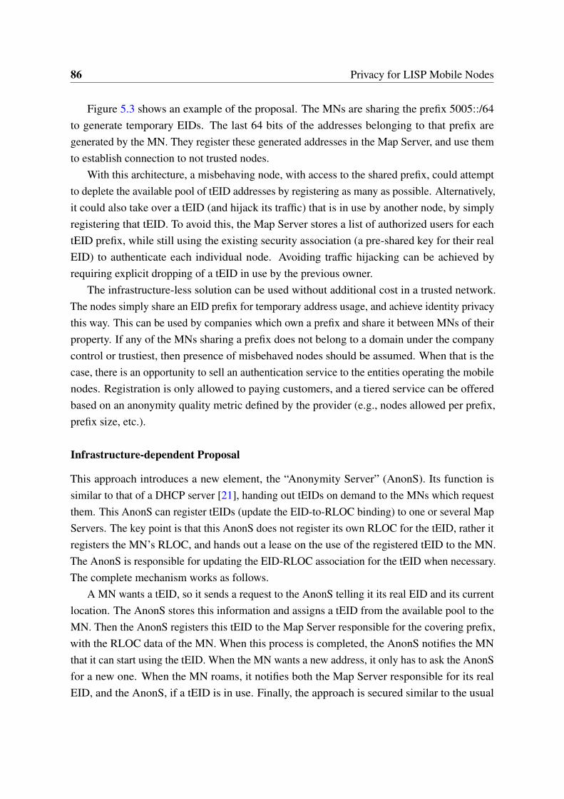
86 Privacy for LISP Mobile Nodes
Figure 5.3 shows an example of the proposal. The MNs are sharing the prefix 5005::/64to generate temporary EIDs. The last 64 bits of the addresses belonging to that prefix aregenerated by the MN. They register these generated addresses in the Map Server, and use themto establish connection to not trusted nodes.
With this architecture, a misbehaving node, with access to the shared prefix, could attemptto deplete the available pool of tEID addresses by registering as many as possible. Alternatively,it could also take over a tEID (and hijack its traffic) that is in use by another node, by simplyregistering that tEID. To avoid this, the Map Server stores a list of authorized users for eachtEID prefix, while still using the existing security association (a pre-shared key for their realEID) to authenticate each individual node. Avoiding traffic hijacking can be achieved byrequiring explicit dropping of a tEID in use by the previous owner.
The infrastructure-less solution can be used without additional cost in a trusted network.The nodes simply share an EID prefix for temporary address usage, and achieve identity privacythis way. This can be used by companies which own a prefix and share it between MNs of theirproperty. If any of the MNs sharing a prefix does not belong to a domain under the companycontrol or trustiest, then presence of misbehaved nodes should be assumed. When that is thecase, there is an opportunity to sell an authentication service to the entities operating the mobilenodes. Registration is only allowed to paying customers, and a tiered service can be offeredbased on an anonymity quality metric defined by the provider (e.g., nodes allowed per prefix,prefix size, etc.).
Infrastructure-dependent Proposal
This approach introduces a new element, the “Anonymity Server” (AnonS). Its function issimilar to that of a DHCP server [21], handing out tEIDs on demand to the MNs which requestthem. This AnonS can register tEIDs (update the EID-to-RLOC binding) to one or several MapServers. The key point is that this AnonS does not register its own RLOC for the tEID, rather itregisters the MN’s RLOC, and hands out a lease on the use of the registered tEID to the MN.The AnonS is responsible for updating the EID-RLOC association for the tEID when necessary.The complete mechanism works as follows.
A MN wants a tEID, so it sends a request to the AnonS telling it its real EID and its currentlocation. The AnonS stores this information and assigns a tEID from the available pool to theMN. Then the AnonS registers this tEID to the Map Server responsible for the covering prefix,with the RLOC data of the MN. When this process is completed, the AnonS notifies the MNthat it can start using the tEID. When the MN wants a new address, it only has to ask the AnonSfor a new one. When the MN roams, it notifies both the Map Server responsible for its realEID, and the AnonS, if a tEID is in use. Finally, the approach is secured similar to the usual
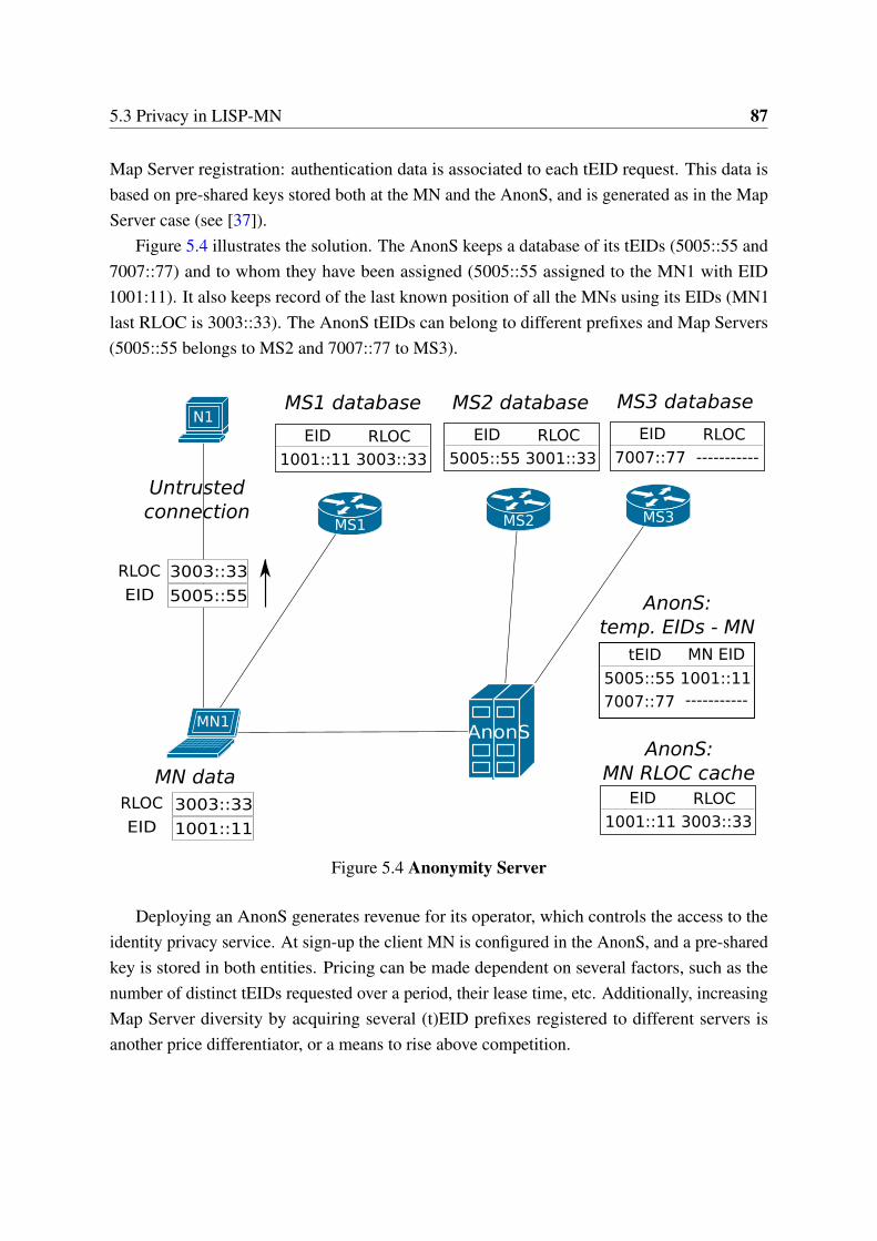
5.3 Privacy in LISP-MN 87
Map Server registration: authentication data is associated to each tEID request. This data isbased on pre-shared keys stored both at the MN and the AnonS, and is generated as in the MapServer case (see [37]).
Figure 5.4 illustrates the solution. The AnonS keeps a database of its tEIDs (5005::55 and7007::77) and to whom they have been assigned (5005::55 assigned to the MN1 with EID1001:11). It also keeps record of the last known position of all the MNs using its EIDs (MN1last RLOC is 3003::33). The AnonS tEIDs can belong to different prefixes and Map Servers(5005::55 belongs to MS2 and 7007::77 to MS3).
MN1
MS1
N1
AnonS
MS2 MS3
tEID MN EID
5005::55 1001::11
AnonS: temp. EIDs - MN
EID RLOC
1001::11 3003::33
AnonS: MN RLOC cache
7007::77
3003::33
5005::55EID
RLOC
EID RLOC
1001::11 3003::33
3003::33
1001::11EID
RLOC
MN data
Untrusted connection
MS1 database
EID RLOC
5005::55 3001::33
MS2 database
EID RLOC
7007::77
MS3 database
-----------
-----------
Figure 5.4 Anonymity Server
Deploying an AnonS generates revenue for its operator, which controls the access to theidentity privacy service. At sign-up the client MN is configured in the AnonS, and a pre-sharedkey is stored in both entities. Pricing can be made dependent on several factors, such as thenumber of distinct tEIDs requested over a period, their lease time, etc. Additionally, increasingMap Server diversity by acquiring several (t)EID prefixes registered to different servers isanother price differentiator, or a means to rise above competition.
88 Privacy for LISP Mobile Nodes
5.4 Related Work
Location privacy in mobility is a well-known issue which Mobile IP has faced up in [70]. Inparticular they use a similar approach as the one presented in Section 5.3.1 to solve it, in thiscase the Home Agent acts as the proxy. The authors of [134] extend this idea by proposing todeploy redundant Home Agents to enhance privacy. Finally, a different approach to locationprivacy has been proposed in [118] where the authors propose to extend Mobile IP to use IPv6”pseudo home addresses”. These addresses are generated in a similar way the ones proposed in[96] are generated for identity privacy. Although these ”pseudo home addresses” are intendedto provide location privacy, they implicitly also serve as an identity-privacy mechanism.
In general, using temporal addresses is a well-known approach to provide identity privacy inthe IPv6 area, being the main proposal the one standardized in [96]. Another good example canbe found in [50]. Note that [96] forces keeping one temporary identifier per connection, whichcan lead to runtime issues related with closing long-term connections and the maximum numberof temporary addresses supported by the system. This can be observed in the current Linuxkernel implementation. On the other hand, mechanisms to hand out addresses from a pool tohosts are also well-known [21]. In this thesis we have taken these established approaches andadapt them to the LISP-MN architecture.
Finally it is worth to note that in this thesis we have focused on solutions for privacy at thenetwork level, however other approaches exist at higher layers. In this context, onion routing isone of the most well-known. Using onion routing, packets traveling through the network havebeen repeatedly encrypted in their origin, and are layer by layer unencrypted by the routers theygo through. This way, routers in the path only know the previous and next hop of the packets.The main idea was originally proposed in [43]. A patent free, improved, and already deployedversion is Tor network [18].
5.5 Analysis
This section discusses the level of security provided by the mechanisms proposed in this chapter,the trade-offs they impose and the feasibility of their implementation.
5.5.1 Location Privacy
The proxy-based approach proposed guarantees that the location of the MN is never exposed toremote nodes, however the use of a proxy introduces an inefficient routing path that degradesthe performance of the LISP-MN communications. To alleviate this, the extensions proposedto improve vanilla proxy selection allow the MN to choose the most suitable RTR for its needs.
5.5 Analysis 89
Particularly the MN can get the geo-location of the proxy and select an RTR based on thatinformation. If that is the case, there is a trade-off on which RTR to select since closer RTRswould provide better performance, but also disclose more data about the potential location ofthe MN. We recommend select randomly from a set of mid-range located RTRs to balanceamong location disclosure and performance degradation. Besides, the load on the RTRs can bealleviated deploying more RTRs and providing their load information to MNs to help to selecta non-overloaded one.
In terms of implementation, an MN compatible with NAT traversal can use the NATtraversal mechanism to get basic location privacy. The usage of the extensions proposed on thischapter requires support for parsing and encoding/decoding the extra information on both sides,i.e. on the MN and on the Mapping System. Additionally, the Mapping Systems needs to getpopulated with the information regarding the RTRs, how to populate the Mapping System withthat information is out of the scope of this chapter.
An RTR-compatible MN requires minor implementation changes in order to use the pro-posed location-privacy solution. A decision process, to decide which nodes are trustworthy ornot, is the only additional code to be implemented. The proposed implementation for this is theuse of a configuration file in the MN, which stores a list of EIDs that the MN will trust. Whenreceiving a query from one of those EIDs, the MN will reply with its real RLOC.
5.5.2 Identity Privacy
In this chapter we propose a simple, yet practical, design of an auto-managed identity privacyby means of auto-generated temporary EIDs that does not require of any new infrastructuredeployment. The trade-offs of this approach are that it only serves for IPv6 addresses, that itimposes extra computation on the MNs and that the MNs are still traceable at prefix level. Weextend it by proposing the Anonymity Severs, which enable the nodes to use identities fromdifferent prefixes, at the cost of requiring new infrastructure elements. Moreover, the use ofdifferent prefixes, gives to the users of an AnonS a higher level of anonymity than the use oftraditional IPv6 privacy mechanisms. In those, the MN still can be tracked at IP prefix level,whereas with the AnonS solution the MN’s EID prefix can be regularly changed among prefixesthat can belong to different domains.
There is what makes the AnonS specially attractive as a mechanism to provide identityprivacy and distinguishes it from the previous presented solution. The MN can use as manyaddresses, even from disjoint prefixes, as it wants. As a result, an attacker tracking tEIDs willhave difficulties to correlate them to a single MN. An anonymity server can work with IPv4,IPv6 or both address families. In contrast to the infrastructure-less approach, using an AnonS
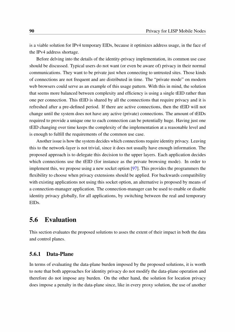
90 Privacy for LISP Mobile Nodes
is a viable solution for IPv4 temporary EIDs, because it optimizes address usage, in the face ofthe IPv4 address shortage.
Before delving into the details of the identity-privacy implementation, its common use caseshould be discussed. Typical users do not want (or even be aware of) privacy in their normalcommunications. They want to be private just when connecting to untrusted sites. Those kindsof connections are not frequent and are distributed in time. The “private mode” on modernweb browsers could serve as an example of this usage pattern. With this in mind, the solutionthat seems more balanced between complexity and efficiency is using a single tEID rather thanone per connection. This tEID is shared by all the connections that require privacy and it isrefreshed after a pre-defined period. If there are active connections, then the tEID will notchange until the system does not have any active (private) connections. The amount of tEIDsrequired to provide a unique one to each connection can be potentially huge. Having just onetEID changing over time keeps the complexity of the implementation at a reasonable level andis enough to fulfill the requirements of the common use case.
Another issue is how the system decides which connections require identity privacy. Leavingthis to the network-layer is not trivial, since it does not usually have enough information. Theproposed approach is to delegate this decision to the upper layers. Each application decideswhich connections use the tEID (for instance as the private browsing mode). In order toimplement this, we propose using a new socket option [97]. This provides the programmers theflexibility to choose when privacy extensions should be applied. For backwards compatibilitywith existing applications not using this socket option, an alternative is proposed by means ofa connection-manager application. The connection-manager can be used to enable or disableidentity privacy globally, for all applications, by switching between the real and temporaryEIDs.
5.6 Evaluation
This section evaluates the proposed solutions to asses the extent of their impact in both the dataand control planes.
5.6.1 Data-Plane
In terms of evaluating the data-plane burden imposed by the proposed solutions, it is worthto note that both approaches for identity privacy do not modify the data-plane operation andtherefore do not impose any burden. On the other hand, the solution for location privacydoes impose a penalty in the data-plane since, like in every proxy solution, the use of another
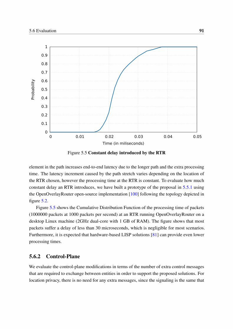
5.6 Evaluation 91
0
0.1
0.2
0.3
0.4
0.5
0.6
0.7
0.8
0.9
1
0 0.01 0.02 0.03 0.04 0.05
Pro
bab
ility
Time (in miliseconds)
Figure 5.5 Constant delay introduced by the RTR
element in the path increases end-to-end latency due to the longer path and the extra processingtime. The latency increment caused by the path stretch varies depending on the location ofthe RTR chosen, however the processing time at the RTR is constant. To evaluate how muchconstant delay an RTR introduces, we have built a prototype of the proposal in 5.5.1 usingthe OpenOverlayRouter open-source implementation [100] following the topology depicted infigure 5.2.
Figure 5.5 shows the Cumulative Distribution Function of the processing time of packets(1000000 packets at 1000 packets per second) at an RTR running OpenOverlayRouter on adesktop Linux machine (2GHz dual-core with 1 GB of RAM). The figure shows that mostpackets suffer a delay of less than 30 microseconds, which is negligible for most scenarios.Furthermore, it is expected that hardware-based LISP solutions [81] can provide even lowerprocessing times.
5.6.2 Control-Plane
We evaluate the control-plane modifications in terms of the number of extra control messagesthat are required to exchange between entities in order to support the proposed solutions. Forlocation privacy, there is no need for any extra messages, since the signaling is the same that
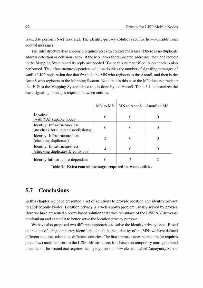
92 Privacy for LISP Mobile Nodes
is used to perform NAT traversal. The identity-privacy solutions require however additionalcontrol messages.
The infrastructure-less approach requires no extra control messages if there is no duplicateaddress detection or collision check. If the MN looks for duplicated addresses, then one requestto the Mapping System and its reply are needed. Twice this number if collision check is alsoperformed. The infrastructure-dependent solution doubles the number of signaling messages ofvanilla LISP registration due that first it is the MN who registers to the AnonS, and then is theAnonS who registers to the Mapping System. Note that in this case the MN does not registerthe tEID to the Mapping System since this is done by the AnonS. Table 5.1 summarizes theextra signaling messages required between entities.
MN to MS MN to AnonS AnonS to MS
Location(with NAT capable nodes) 0 0 0
Identity: Infrastructure-less(no check for duplicates/collisions) 0 0 0
Identity: Infrastructure-less(checking duplicates) 2 0 0
Identity: Infrastructure-less(checking duplicates & collisions) 4 0 0
Identity Infrastructure-dependant 0 2 2
Table 5.1 Extra control messages required between entities
5.7 Conclusions
In this chapter we have presented a set of solutions to provide location and identity privacyto LISP Mobile Nodes. Location privacy is a well-known problem usually solved by proxies.Here we have presented a proxy based solution that takes advantage of the LISP NAT-traversalmechanism and extend it to better serve the location privacy purpose.
We have also proposed two different approaches to solve the identity privacy issue. Basedon the idea of using temporary identifiers to hide the real identity of the MNs we have defineddifferent solutions adapted to different scenarios. The first approach does not require (or requiresjust a few) modifications to the LISP infrastructure, it is based on temporary auto-generatedidentifiers. The second one requires the deployment of a new element called Anonymity Server.
5.7 Conclusions 93
It serves as a kind of DHCP server to provide and manage heterogeneous and distributedtemporary identifiers.
We have addressed both privacy issues taking a realistic approach aiming for deployment.In particular we have briefly discussed the trade-offs of the proposed solutions alongside withthe feasibility of their implementation. The evaluation shows that the burden that the solutionsimpose in the data and control plane operations is reasonable.

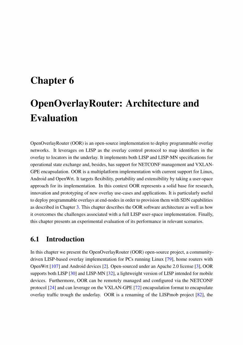
Chapter 6
OpenOverlayRouter: Architecture andEvaluation
OpenOverlayRouter (OOR) is an open-source implementation to deploy programmable overlaynetworks. It leverages on LISP as the overlay control protocol to map identifiers in theoverlay to locators in the underlay. It implements both LISP and LISP-MN specifications foroperational state exchange and, besides, has support for NETCONF management and VXLAN-GPE encapsulation. OOR is a multiplatform implementation with current support for Linux,Android and OpenWrt. It targets flexibility, portability and extensibility by taking a user-spaceapproach for its implementation. In this context OOR represents a solid base for research,innovation and prototyping of new overlay use-cases and applications. It is particularly usefulto deploy programmable overlays at end-nodes in order to provision them with SDN capabilitiesas described in Chapter 3. This chapter describes the OOR software architecture as well as howit overcomes the challenges associated with a full LISP user-space implementation. Finally,this chapter presents an experimental evaluation of its performance in relevant scenarios.
6.1 Introduction
In this chapter we present the OpenOverlayRouter (OOR) open-source project, a community-driven LISP-based overlay implementation for PCs running Linux [79], home routers withOpenWrt [107] and Android devices [2]. Open-sourced under an Apache 2.0 license [3], OORsupports both LISP [30] and LISP-MN [32], a lightweight version of LISP intended for mobiledevices. Furthermore, OOR can be remotely managed and configured via the NETCONFprotocol [24] and can leverage on the VXLAN-GPE [72] encapsulation format to encapsulateoverlay traffic trough the underlay. OOR is a renaming of the LISPmob project [82], the
96 OpenOverlayRouter: Architecture and Evaluation
original implementation of the LISP-MN specification. The LISPmob implementation grew infeatures and capabilities over the years. From a minimal LISP-MN implementation it evolvedinto a full LISP implementation, and from there to a complete overlay solution that incorporatesother protocols beyond LISP.
Despite there are other LISP implementations, both proprietary (Cisco LISP [81]) andopen-source (OpenLISP [113] for BSD systems), OOR has a completely different focus andscope. OOR’s code runs entirely at the user-space and has a common code-base for all itssupported platforms. This software approach allows the OOR community to have a strongfocus on flexibility and customization. Indeed, OOR’s architecture represents a solid base forresearch, innovation and prototyping of new LISP use-cases and applications. A good exampleof OOR’s success is that it is being used by the LISP project in the OpenDayLight [99] SDNcontroller. Additionally, the OOR community has developed liblisp, a standard library to parseLISP messages that simplifies the development and interoperability between different LISPentities/implementations.
OOR is particularly useful to enable an SDN deployment in the end-node scenario describedin Chapter 3. End-nodes to be provisioned with SDN capabilities are likely to require an overlay-oriented data-plane (e.g. VXLAN-GPE) and a pull-based connectionless southbound protocol(e.g. LISP). Such end-nodes can use OOR to fulfill their SDN requirements while leveragingon its support for typical end-node platforms (i.e. Linux, Android, OpenWrt). Furthermore, thehomogenous implementation across platforms (thanks to OOR user-space approach) eases thedeployment of an SDN infrastructure over a wide range of heterogeneous end devices. In thissense, OOR enables the deployment of overlays (like the one depicted in Fig. 6.1) that hide theinherent heterogeneity of the underlay and offer an homogenous view of the overlay networksuitable to be programmed via SDN.
In what follows we describe the OOR software architecture and components, with focus onthe challenges that the community has overcome to implement a full multi-platform LISP user-space implementation. We first give an overview of the main architectural core ideas behindOOR implementation to latter delve into the internals of its software architecture. The analysisof the software architecture is split into data-plane and control-plane. In the data-plane sectionwe describe how OOR encapsulates traffic into LISP data packets and how it decapsulatestraffic from LISP data packets. In the control-plane part, we show how LISP control is managed,both in terms of control packets processing and control state handling. Both data-plane andcontrol-plane are implemented in a single modular user-space daemon. Finally, we presentan experimental evaluation of OOR in relevant scenarios and compare its performance withother related implementations. As the results show, despite taking a user-space approach, OORimplementation results in a remarkable performance suitable for home and edge devices.
6.2 Architecture Overview 97
Physical
Overlay
Figure 6.1 Overlay approach
6.2 Architecture Overview
OOR is an open-source implementation of both LISP [30] (see Section 2.2) and LISP-MN [32](see Section 5.2) developed in C [65] for Linux-flavored systems. The main goal of OOR is torepresent a solid code-base for overlay research, innovation and prototyping with an end-userfocus. To achieve this, OOR comprises a modular architecture with a user-space approach anda multi-platform implementation.
6.2.1 Modular Design
OOR is composed of different software modules. The modules have been abstracted andits interactions well-defined, this allows different components of OOR to be inspected andmodified without disrupting the rest of the system. An overview of the different modulesis depicted in figure 6.2. There are two main modules, control and data which support thecontrol and data planes respectively. The data module handles data packets processing whilethe control module keeps the control state, handles control signaling and manages the mappinginformation that is used by the data module. OOR implements several LISP devices, each ofthese devices is represented with a module that adapts the control and data modules behaviorto match the specific LISP device. Beyond those main modules, there are certain parts of OORthat have been abstracted into auxiliary modules that connect to the main ones, such as the
98 OpenOverlayRouter: Architecture and Evaluation
interface management, the multihoming procedures or the database storage. Finally, OORimplements and makes publicly available the liblisp library to parse LISP packets.
6.2.2 User-Space
All OOR code runs in user-space, this prevents having to delve into hardware specific opti-mizations while avoiding the complexity and high maintenance costs typically associated withkernel code. To support a LISP data-plane on user-space, OOR uses TUN/TAP [138] drivers.Specifically it creates a TUN interface to capture and forward traffic. TUN virtual devicesallow user-space applications to receive and transmit network layer packets. Figure 6.2 depictsOOR components in user-space and how they interact with the kernel space. The data modulehooks to the TUN interface for data processing while the control module opens a socket onthe WAN interface for control signaling. Finally, OOR uses netlink to monitor and modify therouting tables. With this approach, OOR does not need specific support at the kernel and canbe easily ported to different Linux-flavored systems.
6.2.3 Multi-Platform
Since its inception OOR has been oriented towards end-users. In order to do so, it tries toprovide an easy usage and configuration, while at the same time offer LISP features thatrepresent immediate advantage, such seamless mobility or bandwidth aggregation. However, todeliver such benefits to a broader set of end-users, it is mandatory to offer support for differentplatforms. Thanks to its modular architecture and its user-space approach, at the time of thiswriting OOR supports three different platforms using the same code base. Taking base onan implementation for Linux, OOR has been ported to OpenWrt (home routers) and Android(mobile devices). Although with some platform-specific caveats (see Section 6.4.4), most ofthe benefits that OOR offers are available for all the three platforms.
6.3 Control-Plane
The LISP control-plane registers, stores, and resolves EID to RLOC mapping information.This section describes the relevant implementation details of the OOR control-plane, mainlyimplemented by the control module.
LISP control signaling is send and received by means of opening a socket in the LISPcontrol port in the WAN interface. The way it implements control-plane, which control packetsit sends and how it reacts to received control packets is governed by the LISP device that isconfigured. See details on this on 6.3.1. To keep track of periodic events, the control module
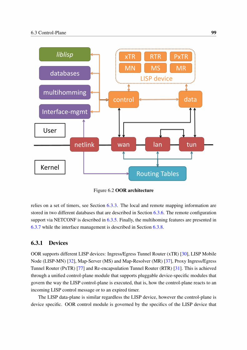
6.3 Control-Plane 99
control data
wan
Interface-mgmt
liblisp
tun
Routing Tables
User
Kernel
lan
databases
xTR RTR
MN MS
LISP device
netlink
multihomming
PxTR
MR
Figure 6.2 OOR architecture
relies on a set of timers, see Section 6.3.3. The local and remote mapping information arestored in two different databases that are described in Section 6.3.6. The remote configurationsupport via NETCONF is described in 6.3.5. Finally, the multihoming features are presented in6.3.7 while the interface management is described in Section 6.3.8.
6.3.1 Devices
OOR supports different LISP devices: Ingress/Egress Tunnel Router (xTR) [30], LISP MobileNode (LISP-MN) [32], Map-Server (MS) and Map-Resolver (MR) [37], Proxy Ingress/EgressTunnel Router (PxTR) [77] and Re-encapsulation Tunnel Router (RTR) [31]. This is achievedthrough a unified control-plane module that supports pluggable device-specific modules thatgovern the way the LISP control-plane is executed, that is, how the control-plane reacts to anincoming LISP control message or to an expired timer.
The LISP data-plane is similar regardless the LISP device, however the control-plane isdevice specific. OOR control module is governed by the specifics of the LISP device that
100 OpenOverlayRouter: Architecture and Evaluation
has been configured, which means that the control module will react in a different way to anincoming control message or to an expired timer depending on the LISP device OOR is runningas.
6.3.2 Control Signaling
LISP control messages are (generally) not LISP encapsulated. OOR sends these packets througha physical output interface. In order to receive LISP control packets from other LISP entities,OOR opens sockets on the LISP control port. When a packet reaches one of these sockets, OORtriggers the control message processing mechanism. How OOR reacts to incoming controlpackets, and which outgoing control packets it sends, depends of the specific LISP deviceOOR is behaving as. OOR will perform different actions, depending on the type of the packetreceived and on which LISP device OOR is acting as. For example, when OOR behaves asa xTR in the case of a Map-Reply, it will store the new arrived mapping on the map-cachedatabase.
6.3.3 Timers
LISP protocol requires performing some actions periodically, for instance when operating as anxTR it has to send control messages to the Mapping System periodically. Besides, some of theinformation stored is only valid for a certain period, after that it is considered outdated and it isdiscarded. OOR keeps track of periodic events using a timer wheel algorithm, similar to theone the Linux kernel uses for its internal timers. Event timers are placed in a wheel structurethat rotates over time. Its position on the wheel indicates when the timer is going to expire.Timers are created with an assigned callback function and related data. Whenever the timerexpires, the callback function is called with the associated data as a parameter.
6.3.4 liblisp
OOR implementation provides the liblisp library to help parse LISP control messages. Thelibrary allows reading raw LISP messages to store them into internal buffers as well as to writeinternal buffers into raw messages. The buffers are accessible through a set of well-definedstructures and functions. This is specially useful to handle packets containing addresses in theLISP Canonical Address Format (LCAF) [33], since liblisp abstracts all the complexity. Theliblisp library is independent from OOR and thus can be used by any LISP implementation orentity to simplify its development or interoperability.
6.3 Control-Plane 101
6.3.5 NETCONF
The main way to configure OOR is via a static configuration file that is read during the boot-upprocess. This file contains information required for the correct operation of the LISP protocolas well as user-configurable aspects of OOR, e.g. which encapsulation format to use. Duringrun-time it is possible to modify parts of this configuration remotely thanks to the NETCONF[24] support that OOR implements. NETCONF support at OOR is based in the libnetconflibrary [78, 73] which offers an open-source C implementation of the NETCONF protocol.OOR implements support for a simplified version of the YANG [6] datamodel for LISP [26]that allows, for instance, to change the Map-Resolver in use or to modify the EID prefixescurrently configured in the local mapping database (see Section 6.3.6).
6.3.6 Databases
OOR stores mappings in two different data structures, depending on whether these mappingsare local or not. The mappings related to EIDs prefixes belonging to the OOR node itself arestored in the mapping database. Mappings related to EIDs belonging to remote nodes arestored in the map-cache. The mapping database is loaded from a configuration file duringboot-up and remains mostly static during OOR execution (unless modified via NETCONFas described in Section 6.3.5). As an example, when running as an xTR this database storesthe EIDs that must be encapsulated and when operating as a Map-Server it stores the EIDsthat OOR is serving. On the other hand the map-cache is dynamically populated during OORoperation, i.e. on a map-cache miss triggered by the data-plane, the control module retrievesthe missing mapping from the Mapping System and stores it on the map-cache.
Despite serving different purposes and being populated in different ways, the two databasesshare a similar internal structure. Both are implemented over a Patricia Trie structure (alsoknown as Radix Tree) that is kept in memory. A Patricia Trie is an optimized version of adigital tree where single-child nodes are merged with their parents. This produces an optimaldata storage for strings that share long prefixes, such the bit-strings of IP addresses. Since LISPmappings are (generally) indexed based on IP prefixes, Patricia Trie databases allow OOR tooptimally store such indexes and to retrieve the most specific prefix for a given IP address.OOR’s modularity supports as well using other databases for non-IP based mappings.
6.3.7 Multihoming
LISP inherently supports multihoming, a LISP mapping can bind a single EID prefix to severalRLOCs and hence, physical interfaces. In the EID-to-RLOC bindings each RLOC may have its
102 OpenOverlayRouter: Architecture and Evaluation
own priority and weight, the priority indicates the preference to use a given locator while theweight describes how the traffic should be balanced in case that several locators have the samepriority. Since LISP sites register their mappings in the publicly accessible Mapping System,the priority and weight values express the inbound traffic engineering policies.
In multihoming scenarios -where several locators are available at the same time- the userhas to define the inbound and outbound traffic policies, this is done by configuring prioritiesand weights for the available locators. OOR does not load-balance traffic per packet but ratherper flow -defined as a sequence of packets identified by the same 5-tuple-. This is done to avoidsplitting flows over different paths that may have different delay/jitter and hence, may severelyimpact the performance.
To balance load among several locators with the same priority, OOR uses weighted vectorscontaining locators. Each mapping (i.e. each EID prefix with a set of locators) has its ownweighted locators vectors. The locators sharing the maximum priority a mapping are distributedalong the mapping vectors according to their weight. For instance, if two locators have weights10 and 15 the multihoming module will assign the 40% of the vector positions to the firstone and the 60% to the second. When OOR needs to select a locator to encapsulate to theEID it chooses one from these vectors. To select the proper locator, it uses a hash function tohaphazardly select a position of the vector. The locator pointed by that vector position will bethe one used. OOR keeps three vectors per locator set, one containing the IPv4 locators withmaximum priority, another the maximum priority IPv6 locators and a third one with both IPv4and IPv6 locators if they share the maximum priority. One or more of these vectors may beempty or be equal to another vector. This is the case when there are no locators for one type, orwhen the maximum priority of one type of locators is not equal to the other type.
OOR uses this selection process to select locators to use both for destination address(belonging to remote site) and source address (belonging to OOR). Since OOR can use bothIPv4 and IPv6 locators, it checks first the IP version of locators available on both sides. Ifthey only have locators from different version, no communication is possible (except by meansof a proxy). If they have locators from at least one common version, the selection process isperformed taking into account just that IP version. If both remote site and OOR have IPv4 andIPv6 locators, all locators are taking into account during the selection process. However, sourcelocators are selected first. That means that if in source locator selection, an IPv6 locator wasselected, during destination locator selection only IPv6 locators will be taken into account. Thelocator balancing vectors are calculated in advance for both OOR local locators and remotesites locators, and kept in memory to be checked when needed.
However, it should be noted that in OOR there is a limitation of just one IPv4 locator andone IPv6 locator per interface (not taking into account IPv6 link-local addresses). For instance,
6.3 Control-Plane 103
if there are two IPv6 global addresses configured in one interface, OOR will use just one ofthem. OOR handles its inbound traffic policies by registering these priorities and weights onthe Mapping System.
Users can take advantage of OOR multihoming capabilities. First, they can deploy active-backup multihoming solutions for disaster recovery scenarios. Second they can make the mostof active-active multihoming deployments thanks to the traffic balancing across the links thatentitles them to perform bandwidth aggregation.
6.3.8 Interface Management
The interface management is critical specially in two scenarios, mobility and multihoming.To support mobility, OOR has to detect handover from one network attachment point toanother. On multihoming scenarios it needs to detect any change on the interfaces to adjustthe announced locators and the load balance vectors. These two scenarios apply to both xTRand MN modes, as a result OOR transparently supports multihomed MNs or mobile routers.Interface management is of key importance in OOR given that it has to seamlessly supportmultihoming and handovers in different platforms and Linux flavors.
In order to manage the system interfaces OOR opens a netlink socket to the kernel, this isused both to modify the routing tables as described in Section 6.4 as well as to monitor changesin these tables or in the network interfaces. The events currently filtered and processed are:interface status up, interface status down, new IP address assigned to an interface and newentries in the routing tables. Such events are processed as follows:
When OOR detects a new IP address assigned to an interface it reacts by updating itsinternal structures and, if needed, the Mapping System information as well as the remote LISPpeers through control signaling. This control message tells them that there has been a changein the mapping information regarding OOR node and that they should update their map-caches.In case of an interface going up or down it follows the same procedure, but it checks if itsmultihoming state is still valid. This is due to the fact that in some cases new locators areavailable or previously available locators are no longer usable. Finally, if OOR detects a newentry on the routing tables it checks if there is a new gateway for any of the interfaces it ismonitoring and, if needed, it updates the routing tables to handle outgoing RLOC packets (seeSection 6.4).
104 OpenOverlayRouter: Architecture and Evaluation
6.4 Data-Plane
This section presents how OOR implements the data-plane of the different LISP devices aswell as the challenges of implementing a user-space LISP data-plane on different platforms.The OOR data-plane is implemented by the data module, which is responsible of encapsulatingand decapsulating data packets. Although some LISP devices do not require data-plane (Map-Server/Map-Resolver), for the remaining devices (xTR, RTR and PxTR) its operation is quitesimilar, only Mobile Nodes (MN) require a slightly different approach. As in the case of thecontrol-plane, the LISP device modules modify according to their particular needs the datamodule operation. Mostly due to its condition of user-space implementation, OOR data-planehas faced some implementation challenges. The specific encapsulation format to be used can bechosen prior to boot-up OOR via a variable in the configuration file. At the time of this writing,OOR implements support for both LISP [30] and VxLAN-GPE [72] encapsulation formats.
6.4.1 Tunnel Routers (xTR, RTR, PxTR)
OOR implements the data-plane for all LISP tunnel router devices (xTR, RTR, PxTR) with asimilar approach. This section describes the data-plane as for an xTR, pointing out the specificdetails of RTR and PxTR data-planes when needed.
For outgoing traffic (i.e. from EID space to RLOC space) OOR needs to capture EID spacetraffic, encapsulate and forward it. In order to intercept the outgoing EID traffic (both on xTRand PxTR modes) OOR redirects it to the TUN interface and retrieves it. The redirection isachieved by means of modifying the Linux routing tables and routing rules. In xTR mode,since local traffic does not have to be encapsulated, the new routes and rules forward to TUN allEID space outgoing traffic that is not addressed to the local EID space itself. RTRs operate onRLOC space and hence they receive EID traffic encapsulated directly from an RLOC interface.
With the EID traffic, OOR builds the outer headers using RLOC addresses (governed bythe control module). To speed-up the processing time, the data module keeps a hash table withinformation from already processed packets to avoid querying the control module per-packetbasis. OOR writes the encapsulated traffic in a raw socket, this injects the traffic again on theLinux routing system.
In multihomed scenarios with several default routes OOR must ensure that Linux choosesthe appropriate outbound interface. In order to achieve this OOR creates, for each RLOCinterface, a table that only includes a route to the gateway of the interface and in turn, for eachtable, a rule that matches packets using that particular source RLOC.
To manage incoming traffic (i.e. from the RLOC space to the EID space) OOR opens astandard UDP socket listening for LISP data traffic. Received RLOC traffic is decapsulated

6.4 Data-Plane 105
and written in the TUN interface, then the kernel forwards the EID packet to the EID space. InRTR mode the traffic is re-encapsulated with new RLOC headers and forwarded back to theRLOC space.
6.4.2 Mobile Node (MN)
Although a LISP-MN operates fundamentally as an xTR, additional considerations must betaken into account. The major difference between an xTR and a MN is that a LISP tunnelrouter (xTR) receives the packets from an external source, while in a LISP mobile node (MN)such packets are generated -by the applications running- in the device itself. In mobile nodeoperation the TUN interface must be provisioned with the mobile node EID address. Theapplications running on the MN bind sockets to that interface and hence they use as a sourceaddress the EID. In order to enforce that all the applications bind to the TUN interface, OORconfigures it as the most preferable route for non-local traffic. Additionally, it configures alsospecific tables and rules per each RLOC interface and therefore, once encapsulated, traffic willbe forwarded to the correct outgoing interface preventing loops.
On reception in Linux, OOR deactivates reverse path forwarding (RPF) verifying mecha-nisms to prevent discarded packets. In Linux RPF works as follows, for every received packetthe kernel checks -according to its routing tables- the output interface for that particular sourceaddress. If the input interface is different from the output interface, the RPF mechanismdiscards the packet as an anti-spoofing mechanism. While OOR is running, Linux detects thatany non-local destination address is reached through the TUN interface, thus packets arrivingvia a physical interface would not pass the RPF check.
6.4.3 IPv6 Encapsulation
OOR is agnostic to the address family of the underlay. It supports both IPv4 and IPv6, whichserves to overcome any transition scenario. Users can deploy OOR to get IPv6 access over aIPv4 only connection, or to get IPv4 over IPv6. However, receiving encapsulated data packetson user-space using IPv6 sockets requires a different approach than for IPv4. Both LISPand VxLAN-GPE are UDP encapsulated protocols and their specifications state that the UDPchecksum of the encapsulation header should be zero, however the IPv6 standard specifies thatthe UDP checksum must be computed.
As a result, the Linux kernel automatically drops incoming IPv6+UDP packets with zerochecksum. To overcome this issue OOR uses raw UDP input sockets instead of commonUDP binded-to-port sockets therefore OOR captures all UDP packets and processes only the
106 OpenOverlayRouter: Architecture and Evaluation
ones addressed to the LISP or VxLAN-GPE port. This approach allows OOR to receive IPv6zero-checksum UDP packets.
Additionally, the encapsulation and decapsulation operations require access to low leveldetails of the IP headers such as the TTL or ToS value. Outgoing packets are received withfull IP headers at the TUN interface, however incoming packets require a different approach.For IPv4, input raw sockets provide all the required IPv4 header fields at the user-spacehowever IPv6 raw sockets only provide the IP payload. In order to obtain the IPv6 headerinformation OOR uses IPv6 specific socket options: IPV6_HOPLIMIT to get IPv6 TTL valueand IPV6_TCLASS to get the ToS value.
6.4.4 Non-rooted Android
The key challenge when implementing LISP in Android is that, as shown in previous sections,OOR requires root access because -for instance- it makes use of raw sockets. Since thisrequirement strongly limits the deployability of LISP on smartphones, to overcome this issuethe OOR community has developed a non-rooted Android application. On that scenario someroot-only features are not available, and thus some workarounds are needed.
The lack of root access is partially alleviated by the use of the Android VPN API[141](present from Android 4.0 onwards). The VPN API must be used from a Java application. Onthe Android version of OOR, there is a wrapper application written on Java that calls the nativeOOR C application through JNI (Java Native Interface) [62]. VPN API allows applicationsrunning without root privileges to create a TUN interface, this interface is managed by theAndroid VPN service itself rather than by the application. The interface creation requires ofexplicit user permission (i.e. a pop-up is shown in the device display). Android VPN API doesnot allow the fine grain forwarding achieved with root access, however it does allow setting asocket as protected. The traffic sent through a protected socket will ignore the TUN interface.OOR takes advantage of this to send traffic once it has been LISP encapsulated, the system willautomatically select the outgoing interface among the available physical interfaces and will usethe address assigned to that interface as the source RLOC address for the encapsulated traffic.
Since on non-rooted devices there is no access to the routing tables and rules, neitherto the source address of the encapsulated packets, multihoming is not available on thosedevices. There are not raw sockets available either, which means that incoming IPv6 trafficcan not be directly retrieved. As discussed in Section 6.4.3, if an IPv6 packet arrives withzero checksum, the system will drop it. At the time of this writing, most of the current LISPimplementations, such as those deployed at the beta-network [80], do not compute the outerheader UDP checksum when encapsulating packets into LISP. In practice this implies that IPv6RLOCs functionality on non-rooted Android devices is very limited.

6.5 Evaluation 107
6.5 Evaluation
This section presents an experimental evaluation of the performance of OOR. At the best of ourknowledge OOR is the only mature LISP implementation that takes a full user-space approachand thus, there are no reference implementations to compare. Instead, and when relevant, wecompare the OOR performance with OpenLISP [113], a BSD kernel LISP implementation andOpenVPN [102], a well-known VPN software that also encapsulates packets at the user-space.
0
100
200
300
400
500
600
700
800
900
1000
0 100 200 300 400 500 600 700 800 900 1000
Traffi
c out
(mb
ps)
Traffic in (mbps)
OOROpenLISP
Vanilla
Figure 6.3 Throughput (Linux)
6.5.1 Throughput
Here we focus on the throughput of the OOR data-plane, OOR is compiled for Linux andinstalled in two Intel Core 2 PCs (3GHz, 4GB RAM) running Ubuntu 14.04, both machines areconnected over a dedicated Gigabit Ethernet link. OpenLISP 2.0.2 runs on the same machineswith FreeBSD 9.2. The traffic is generated using the nuttcp tool (UDP packets of 1388 bytes)and we monitor both input and ouput rate.
As the figure 6.3 shows, OOR scales close to the link capacity with a maximum throughputof 800Mbps, at this rate the user-space OOR process is using all the available CPU. OpenLISPwith its kernel implementation is very close to the link capacity.
We also compare the throughput of the Android and OpenWrt OOR versions and compareit to OpenVPN (1.1.14 for Android, 2.2.2 for OpenWrt) on which, for the fairness of the
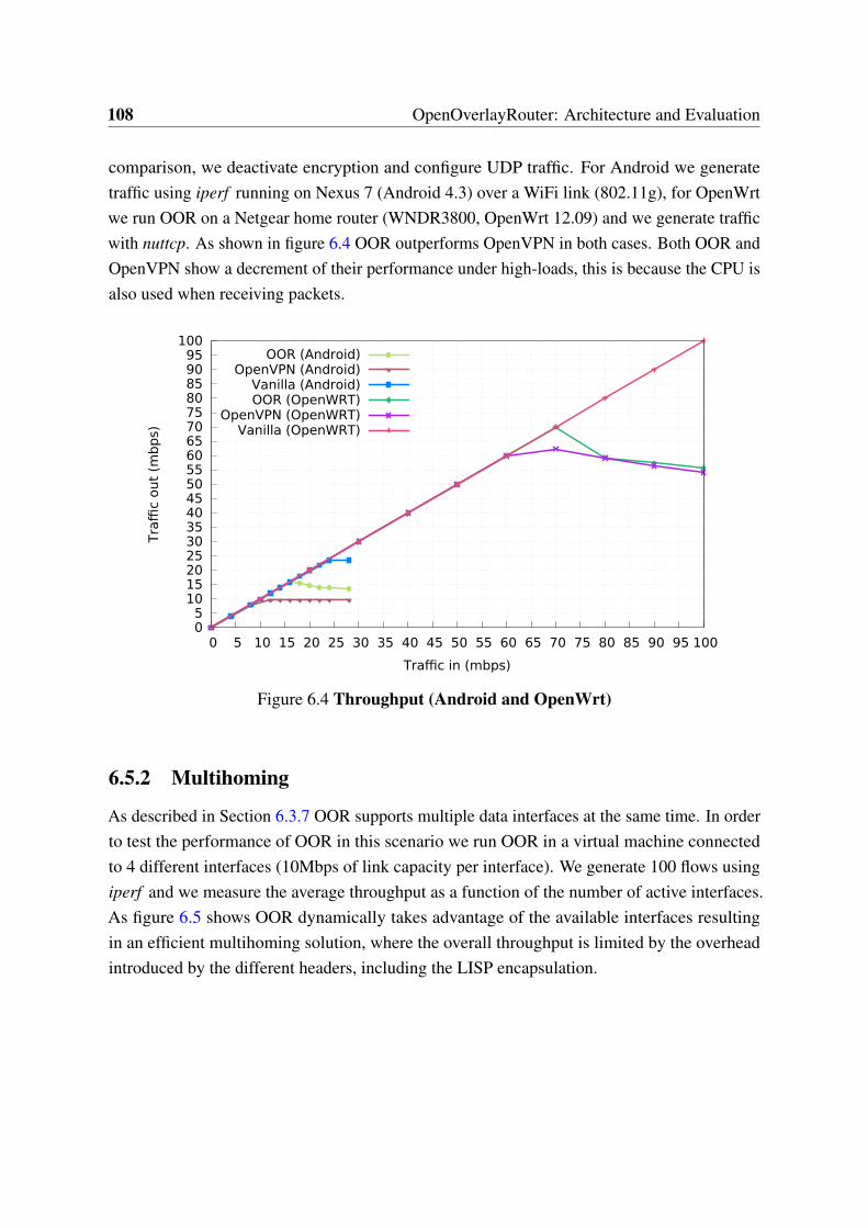
108 OpenOverlayRouter: Architecture and Evaluation
comparison, we deactivate encryption and configure UDP traffic. For Android we generatetraffic using iperf running on Nexus 7 (Android 4.3) over a WiFi link (802.11g), for OpenWrtwe run OOR on a Netgear home router (WNDR3800, OpenWrt 12.09) and we generate trafficwith nuttcp. As shown in figure 6.4 OOR outperforms OpenVPN in both cases. Both OOR andOpenVPN show a decrement of their performance under high-loads, this is because the CPU isalso used when receiving packets.
0 5
10 15 20 25 30 35 40 45 50 55 60 65 70 75 80 85 90 95
100
0 5 10 15 20 25 30 35 40 45 50 55 60 65 70 75 80 85 90 95 100
Traffi
c out
(mb
ps)
Traffic in (mbps)
OOR (Android)OpenVPN (Android)
Vanilla (Android)OOR (OpenWRT)
OpenVPN (OpenWRT)Vanilla (OpenWRT)
Figure 6.4 Throughput (Android and OpenWrt)
6.5.2 Multihoming
As described in Section 6.3.7 OOR supports multiple data interfaces at the same time. In orderto test the performance of OOR in this scenario we run OOR in a virtual machine connectedto 4 different interfaces (10Mbps of link capacity per interface). We generate 100 flows usingiperf and we measure the average throughput as a function of the number of active interfaces.As figure 6.5 shows OOR dynamically takes advantage of the available interfaces resultingin an efficient multihoming solution, where the overall throughput is limited by the overheadintroduced by the different headers, including the LISP encapsulation.
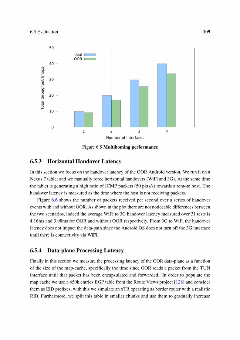
6.5 Evaluation 109
0
10
20
30
40
50
1 2 3 4
Tota
l th
roug
hp
ut
(mb
ps)
Number of interfaces
IdealOOR
Figure 6.5 Multihoming performance
6.5.3 Horizontal Handover Latency
In this section we focus on the handover latency of the OOR Android version. We run it on aNexus 7 tablet and we manually force horizontal handovers (WiFi and 3G). At the same timethe tablet is generating a high ratio of ICMP packets (50 pkts/s) towards a remote host. Thehandover latency is measured as the time where the host is not receiving packets.
Figure 6.6 shows the number of packets received per second over a series of handoverevents with and without OOR. As shown in the plot there are not noticeable differences betweenthe two scenarios, indeed the average WiFi to 3G handover latency measured over 31 tests is4.16ms and 3.98ms for OOR and without OOR respectively. From 3G to WiFi the handoverlatency does not impact the data-path since the Android OS does not turn off the 3G interfaceuntil there is connectivity via WiFi.
6.5.4 Data-plane Processing Latency
Finally in this section we measure the processing latency of the OOR data-plane as a functionof the size of the map-cache, specifically the time since OOR reads a packet from the TUNinterface until that packet has been encapsulated and forwarded. In order to populate themap cache we use a 450k entries BGP table from the Route Views project [128] and considerthem as EID prefixes, with this we simulate an xTR operating as border router with a realisticRIB. Furthermore, we split this table in smaller chunks and use them to gradually increase
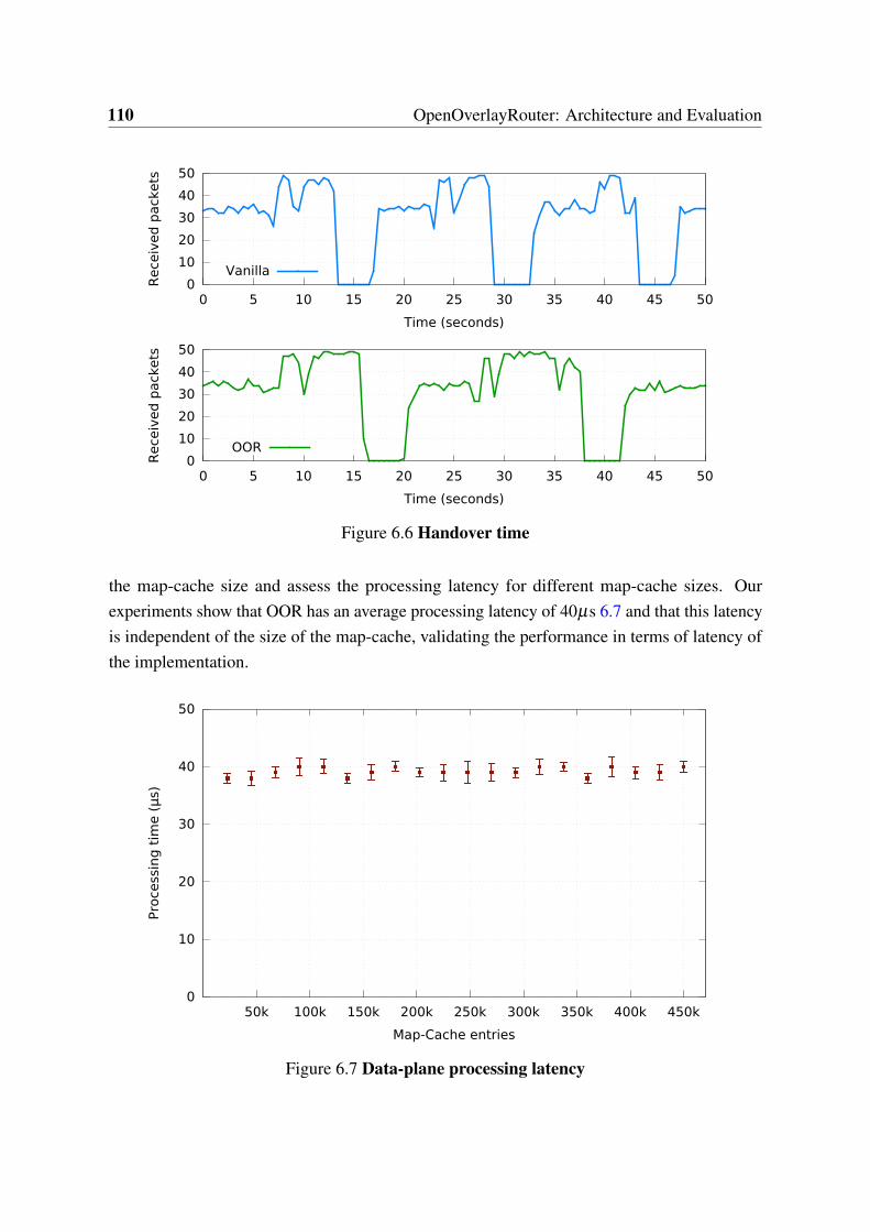
110 OpenOverlayRouter: Architecture and Evaluation
0
10
20
30
40
50
0 5 10 15 20 25 30 35 40 45 50
Rece
ived
pack
ets
Time (seconds)
OOR
0
10
20
30
40
50
0 5 10 15 20 25 30 35 40 45 50
Rece
ived
pack
ets
Time (seconds)
Vanilla
Figure 6.6 Handover time
the map-cache size and assess the processing latency for different map-cache sizes. Ourexperiments show that OOR has an average processing latency of 40µs 6.7 and that this latencyis independent of the size of the map-cache, validating the performance in terms of latency ofthe implementation.
0
10
20
30
40
50
50k 100k 150k 200k 250k 300k 350k 400k 450k
Pro
cess
ing
tim
e (μ
s)
Map-Cache entries
Figure 6.7 Data-plane processing latency
6.6 Conclusions 111
6.6 Conclusions
The OOR project provides a mature user-space LISP implementation for research, innovationand prototyping. The code has been architected with this in mind, providing an extensibleand flexible LISP implementation while keeping low complexity and easy deployment. Thefeedback received from the community as well as the diverse projects where OOR’s code isbeing used strongly supports these claims.
Additionally, the experimental evaluation shows a remarkable performance of the OORcontrol-plane in terms of processing and handover latency, resulting in unnoticeable overheadon the system. The OOR data-plane presents a comparable performance with similar softwaresolutions (e.g., OpenVPN). Such results shows that OOR, despite taking a full user-spaceapproach, is suitable for production in edge and home environments, such as smartphones andhome routers.


Chapter 7
Conclusions
7.1 Thesis Summary
The main contribution of this thesis is the concept of decoupling state and control in SDNnetworks. This architectural distinction reduces the complexity of controller design and allowsto face the scalability challenges of each element (i.e. control and state) individually. In thefirst part of this thesis we have analyzed LISP as a southbound protocol suitable to be used forstate exchange in decoupled-state architectures. Then, partially leveraging on LISP, this thesishas proposed two different decoupled-state SDN architectures for two specific use-cases.
On one hand, we have introduced an asynchronous decoupled-state architecture to enableSDN for end-nodes. It leverages on a distributed state database that offers a connectionless pull-based interface to southbound nodes. The state database is then connected to a decentralizedand symmetric controller that exposes an intent-based interface to northbound applications.The abstract northbound polices are rendered by the controller into specific state and stored inthe state database. Southbound nodes retrieve on demand state directly from the state database.On the other hand, this thesis has described a decentralized SDN architecture designed tosupport NFV on operator networks. This proposal decentralizes the controller instances andpushes them close to the data-plane devices they control. The state is kept in a centralized andglobal database that is shared among all the controllers to enable state federation and globalcoordination.
In the second part of this thesis we have gone in deep into the requirements and char-acteristics of SDN for end-nodes. Particularly, we have described the LISP protocol whenapplied to mobility scenarios and discussed location and identity privacy enhancements forLISP mobile end-nodes. To conclude the thesis we have presented the OpenOverlayRouterproject, an open-source implementation to deploy LISP-based programmable overlays.
114 Conclusions
7.2 Open Research
This work has introduced decoupled-state architectures, a new sub-field within SDN researchthat to the best of our knowledge has never been discussed before. This thesis shows themotivation behind the idea of decoupling state and control and remarks the benefits of applyingdecoupled-state architectures to certain use-cases and scenarios. However, this new area presenta set of new research challenges that can be extracted from the work discussed in this thesis. Inthis section we highlight open research on the field of decoupled-state architectures and thefuture work to be addressed in order to accomplish the full potential of such architectures. Weforesee two particular challenges that need to be addressed in the near future, the description ofthe interfaces to interact with the state and the definition of the requirements of the databasesstoring the decoupled-state.
7.2.1 State Interfaces
SDN defines clear interfaces (e.g. northbound, southbound) between the different SDN compo-nents [48, 61, 132]. In common SDN architectures there is no well-defined interface betweenstate and control since there is no clear boundary between them. There is no need to explicitlydefine a control⇔state interface since they are considered parts of a single entity. In thiscontext, each SDN approach defines the interaction of control and state within the controlleraccording to their own particular needs. However, logically dissociating the state from thecontroller introduces the need to define a clear interface between them. This is comparableto the decoupling of the control-plane from the data-plane in early days of SDN that definedthe southbound interface. Similarly, it is also closely related to the extraction of the controlapplications from the controller that introduced the northbound interface in the SDN paradigm.
Furthermore, once the state is logically outside the controller it is possible to defineadditional interfaces with other SDN components. It is specially interesting to consider thedirect interaction of the state with the data-plane devices. In this sense, this thesis investigatedthe interaction of the controller with a disjoint state entity in Chapter 4 and the direct stateexchange between the state database and the data-plane devices in Chapter 3. Despite thisinitial research, further investigation is required to define the requirements of the control⇔stateand state⇔data interfaces.
On one hand, in many use-cases the interface to exchange state between the controllerand the state database can leverage on the common database interfaces available today. Thisis the case for instance in our proposal in Section 3.5.2 where the controller connects to aCassandra-based state database making use of a regular Cassandra client driver. However, therequirements of this interface needs to be carefully analyzed per use-case and scenario. On the
7.2 Open Research 115
other hand, the interface to expose the state to the data-plane devices likely needs to be fast andlightweight, as discussed in Chapter 3. This also applies to the controller⇔state interface whenthe controller requires of fast and frequent queries to a remote decoupled-state. This is the caseof the decentralized controlled introduced in Chapter 4.
This thesis proposes to use LISP as the state exchange interface for the aforementionedcases where a regular database driver is not the most suitable approach. We choose LISPto fulfill this role due to its lightweight approach and the easiness to leverage on its alreadydefined architecture and signaling. However, we believe that further approaches should beconsidered in the future since different cases may require different approximations. Someexamples of other candidates that, depending on the scenario, may be taken into accountare gRPC [46] + ProtoBuff [117] and NETCONF [24] + YANG [6]. The former presentsan interesting short-lived connection-oriented approach. It can help to mitigate the inherentdrawbacks of connectionless proposals (e.g. LISP) without adding the common overhead ofconnection-based protocols. The latter offers a full connection-oriented proposal, with theoverhead that it implies. However, its wide adoption allows it to be used on scenarios whereno other approach is feasible. Furthermore, the flexible YANG datamodels could be directlymapped to the state structure on the database which opens interesting possibilities. For instance,to automatically generate model-based interfaces on demand in the manner of OpenDaylight[89].
7.2.2 State Databases
This work presents network architectures that heavily depend on databases and we believe thatfurther research and analysis is needed to better understand the implications of this dependence.It should be noted that a partial database dependency has been in place through the differentiterations of SDN controllers [47, 71, 59, 5]. As an example, the authors of ONOS [5] provide alarge discussion on the state tradeoffs addressed by their architecture and describe the differentdatabase choices they considered in order fit the requirements of their scenario.
However, the logical decoupling of state from control and the resulting extraction of thestate database from the logical boundaries of the controller stresses the role of the state database.Taking the state out alleviates the scalability requirements on the controller, but moves them tothe state database. Therefore, the scalability of the SDN architecture is no longer mostly tiedto the scalability of the controller, but rather to the scalability of the state database. Similarly,some technical requirements and constrains previously associated to the SDN controller arenow moved to the state database.
In this sense, existing research on SDN controllers has to be revisited from a decoupled-statepoint of view, to asses whether the results of that research remain valid for decoupled-state
116 Conclusions
architectures. Particularly interesting works are those that focus on aspects directly related tothe state, for instance the implications of a distributed state across different partitions [76], thetopological placement of these partitions [53], how to distribute the specific state across them[112] or how to ensure safe state transactions on a shared environment [10]. As an example,this thesis has already shown in section 3.7 how the topological location of the state has animportant impact on the performance of decoupled-state SDN architectures.
Furthermore, decoupled-state architectures require making an efficient usage of the under-lying database technology (as briefly discussed in Section 3.6). First, per each use-case andscenario the architecture has to find a database that suits its needs in terms of the CAP theorem(Consistency, Availability and Partition tolerance) [8, 7]. In common SDN deployments thisis usually handled via solutions that offer high availability and partition tolerance by meansof only offering eventual consistency. This is the case for the state database (e.g. Cassandra)that we use in Chapter 3 and Chapter 4. Second, the database needs to meet the architecturerequirements in terms of available features, for instance how it handles merging overlappinginformation or if it allows to define callbacks functions to be triggered when certain state ismodified. As an example, in Section 3.5.3 we rely on Cassandra triggers [136] to notify stateupdates to data-plane nodes.
Finally, the database deployment must fulfill the performance requirements of the archi-tecture in both throughput (request per second) and delay (time per request). Decoupled-statearchitectures potentially introduce an additional burden on the latter since in some scenariosthe state can be not only decoupled but also topologically far from the controller or data-planedevices. This could add extra latency to the state retrieval or modification and should becarefully considered during the design of decoupled-state architectures.
7.2.3 Long Term Research
The decoupling of state from control enables new research possibilities to be considered in thelong term. Particularly, at the time of this writing we are starting to explore the application ofMachine Learning (ML) techniques to extract knowledge from the decoupled-state. We believethat the vision described by D. Clark et al. in the paper A Knowledge Plane for the Internet[15] can be accomplished today by leveraging on the SDN architectures. Within this context,decoupled-state SDN architectures may play a major role.
In general, the state centralization brought by SDN makes possible to use ML-basedsolutions that were not feasible to apply over a distributed setup. Furthermore, the decouplingand isolation of the state proposed by decoupled-state architectures eases its parsing by MLapplications. In a decoupled-state architecture the state is directly exposed to third parties,thus a ML application can extract knowledge from the state database while minimizing the

7.2 Open Research 117
disruption of the system. This generated knowledge can be later used to optimize differentmetrics across the system. Moreover, due to the open access to the database, it is easy for anapplication leveraging on the extracted knowledge to modify the network state directly. Thefield of applying ML for network control loops is still open research and the application of it todecoupled-state SDN architectures remains to be explored in the future.

Bibliography
[1] Amazon AWS (2016). Amazon Web Services. https://aws.amazon.com/. Accessed:2016-04-28.
[2] Android (2016). Google Android. http://android.com/. Accessed: 2016-04-20.
[3] Apache (2004). Apache Software License 2.0. http://www.apache.org/licenses/LICENSE-2.0.
[4] Barkai, S., Farinacci, D., Meyer, D., Maino, F., Ermagan, V., Rodriguez-Natal, A., andCabellos-Aparicio, A. (2015). LISP Based FlowMapping for Scaling NFV. Internet-Draftdraft-barkai-lisp-nfv-07, Internet Engineering Task Force. Work in Progress.
[5] Berde, P., Gerola, M., Hart, J., Higuchi, Y., Kobayashi, M., Koide, T., Lantz, B., O’Connor,B., Radoslavov, P., Snow, W., et al. (2014). ONOS: towards an open, distributed SDN OS.In Proceedings of the third workshop on Hot topics in software defined networking, pages1–6. ACM.
[6] Bjorklund, M. (2010). YANG - A Data Modeling Language for the Network ConfigurationProtocol (NETCONF). RFC 6020, RFC Editor. http://www.rfc-editor.org/rfc/rfc6020.txt.
[7] Brewer, E. (2012). CAP twelve years later: How the" rules" have changed. Computer,45(2):23–29.
[8] Brewer, E. A. (2000). Towards Robust Distributed Systems (Abstract). In Proceedings ofthe Nineteenth Annual ACM Symposium on Principles of Distributed Computing, PODC’00, pages 7–, New York, NY, USA. ACM.
[9] Callon, R. (1990). Use of OSI IS-IS for routing in TCP/IP and dual environments. RFC1195, RFC Editor. http://www.rfc-editor.org/rfc/rfc1195.txt.
[10] Canini, M., Kuznetsov, P., Levin, D., and Schmid, S. (2013). Software transactionalnetworking: Concurrent and consistent policy composition. In Proceedings of the secondACM SIGCOMM workshop on Hot topics in software defined networking, pages 1–6. ACM.
[11] Casado, M., Foster, N., and Guha, A. (2014). Abstractions for software-defined networks.Communications of the ACM, 57(10):86–95.
[12] Casado, M., Freedman, M. J., Pettit, J., Luo, J., McKeown, N., and Shenker, S. (2007).Ethane: taking control of the enterprise. In ACM SIGCOMM Computer CommunicationReview, volume 37, pages 1–12. ACM.
120 Bibliography
[13] Casado, M., Koponen, T., Shenker, S., and Tootoonchian, A. (2012). Fabric: a retrospec-tive on evolving SDN. In Proceedings of the first workshop on Hot topics in software definednetworks, pages 85–90. ACM.
[14] Cerrato, I., Palesandro, A., Risso, F., Suñé, M., Vercellone, V., and Woesner, H. (2015).Toward dynamic virtualized network services in telecom operator networks. ComputerNetworks, 92:380–395.
[15] Clark, D. D., Partridge, C., Ramming, J. C., and Wroclawski, J. T. (2003). A knowledgeplane for the internet. In Proceedings of the 2003 conference on Applications, technologies,architectures, and protocols for computer communications, pages 3–10. ACM.
[16] Coras, F., Cabellos-Aparicio, A., and Domingo-Pascual, J. (2012). An analytical modelfor the LISP cache size. In NETWORKING 2012, pages 409–420. Springer.
[17] Dijkstra, E. W. (1959). A note on two problems in connexion with graphs. Numerischemathematik, 1(1):269–271.
[18] Dingledine, R., Mathewson, N., and Syverson, P. (2004). Tor: The second-generationonion router. Technical report, DTIC Document.
[19] Dixit, A., Hao, F., Mukherjee, S., Lakshman, T., and Kompella, R. (2013). Towards anelastic distributed SDN controller. In ACM SIGCOMM Computer Communication Review,volume 43, pages 7–12. ACM.
[20] Doria, A., Salim, J. H., Haas, R., Khosravi, H., Wang, W., Dong, L., Gopal, R., andHalpern, J. (2010). Forwarding and Control Element Separation (ForCES) Protocol Specifi-cation. RFC 5810, RFC Editor. http://www.rfc-editor.org/rfc/rfc5810.txt.
[21] Droms, R. (1997). Dynamic Host Configuration Protocol. RFC 2131, RFC Editor.http://www.rfc-editor.org/rfc/rfc2131.txt.
[22] Eddy, W. M. (2004). At what layer does mobility belong? Communications Magazine,IEEE, 42(10):155–159.
[23] Emmerich, P., Raumer, D., Wohlfart, F., and Carle, G. (2014). Performance characteris-tics of virtual switching. In Cloud Networking (CloudNet), 2014 IEEE 3rd InternationalConference on, pages 120–125. IEEE.
[24] Enns, R., Bjorklund, M., Schoenwaelder, J., and Bierman, A. (2011). Network Configura-tion Protocol (NETCONF). RFC 6241 (Proposed Standard).
[25] Ermagan, V., Farinacci, D., Lewis, D., Skriver, J., Maino, F., and White, C. (2016). NATtraversal for LISP. Internet-Draft draft-ermagan-lisp-nat-traversal-10, Internet EngineeringTask Force. Work in Progress.
[26] Ermagan, V., Rodriguez-Natal, A., Coras, F., Moberg, C., Cabellos-Aparicio, A., andMaino, F. (2015). LISP Configuration YANG Model. Internet-Draft draft-ietf-lisp-yang-01,Internet Engineering Task Force. Work in Progress.
Bibliography 121
[27] ETSI Group Specification (2014a). Network Functions Virtualisation (NFV); Archi-tectural Framework. Specification V1.2.1, European Telecommunications StandardsInstitute (ETSI). http://www.etsi.org/deliver/etsi_gs/NFV/001_099/002/01.02.01_60/gs_NFV002v010201p.pdf.
[28] ETSI Group Specification (2014b). Network Functions Virtualisation (NFV); Manage-ment and Orchestration . Specification V1.1.1, European Telecommunications StandardsInstitute (ETSI). http://www.etsi.org/deliver/etsi_gs/NFV-MAN/001_099/001/01.01.01_60/gs_NFV-MAN001v010101p.pdf.
[29] Falaki, H., Mahajan, R., Kandula, S., Lymberopoulos, D., Govindan, R., and Estrin, D.(2010). Diversity in smartphone usage. In Proceedings of the 8th international conferenceon Mobile systems, applications, and services, pages 179–194. ACM.
[30] Farinacci, D., Fuller, V., Meyer, D., and Lewis, D. (2013). The Locator/ID SeparationProtocol (LISP). RFC 6830, RFC Editor. http://www.rfc-editor.org/rfc/rfc6830.txt.
[31] Farinacci, D., Kowal, M., and Lahiri, P. (2016a). LISP Traffic Engineering Use-Cases.Internet-Draft draft-farinacci-lisp-te-10, Internet Engineering Task Force. Work in Progress.
[32] Farinacci, D., Lewis, D., Meyer, D., and White, C. (2016b). LISP Mobile Node. Internet-Draft draft-meyer-lisp-mn-14, Internet Engineering Task Force. Work in Progress.
[33] Farinacci, D., Meyer, D., and Snijders, J. (2016c). LISP Canonical Address Format(LCAF). Internet-Draft draft-ietf-lisp-lcaf-13, Internet Engineering Task Force. Work inProgress.
[34] Farrel, A., Vasseur, J.-P., and Ash, J. (2006). A Path Computation Element (PCE)-BasedArchitecture. RFC 4655, RFC Editor. http://www.rfc-editor.org/rfc/rfc4655.txt.
[35] Feamster, N., Rexford, J., and Zegura, E. (2014). The road to SDN: an intellectualhistory of programmable networks. ACM SIGCOMM Computer Communication Review,44(2):87–98.
[36] Foster, N., Guha, A., Reitblatt, M., Story, A., Freedman, M. J., Katta, N. P., Monsanto,C., Reich, J., Rexford, J., Schlesinger, C., et al. (2013). Languages for software-definednetworks. Communications Magazine, IEEE, 51(2):128–134.
[37] Fuller, V. and Farinacci, D. (2013). Locator/ID Separation Protocol (LISP) Map-ServerInterface. RFC 6833, RFC Editor.
[38] Fuller, V., Lewis, D., Ermagan, V., Jain, A., and Smirnov, A. (2016). LISP DelegatedDatabase Tree. Internet-Draft draft-ietf-lisp-ddt-06, Internet Engineering Task Force. Workin Progress.
[39] Galvani, A., Rodriguez-Natal, A., Cabellos-Aparicio, A., and Risso, F. (2014). LISP-ROAM: network-based host mobility with LISP. In Proceedings of the 9th ACM workshopon Mobility in the evolving internet architecture, pages 19–24. ACM.
[40] Garg, P. and Wang, Y. (2015). NVGRE: Network Virtualization Using Generic RoutingEncapsulation. RFC 7637, RFC Editor.
122 Bibliography
[41] GBP (2015). Group Based Policy abstractions for OpenStack. https://wiki.openstack.org/GroupBasedPolicy. Accessed: 2015-03-13.
[42] Gember-Jacobson, A., Viswanathan, R., Prakash, C., Grandl, R., Khalid, J., Das, S.,and Akella, A. (2015). OpenNF: Enabling innovation in network function control. ACMSIGCOMM Computer Communication Review, 44(4):163–174.
[43] Goldschlag, D. M., Reed, M. G., and Syverson, P. F. (1996). Hiding routing information.In Information Hiding, pages 137–150. Springer.
[44] Greenberg, A., Hjalmtysson, G., Maltz, D. A., Myers, A., Rexford, J., Xie, G., Yan,H., Zhan, J., and Zhang, H. (2005). A clean slate 4D approach to network control andmanagement. ACM SIGCOMM Computer Communication Review, 35(5):41–54.
[45] Greene, K. (2009). TR10: Software-defined networking. Technology Review (MIT).http://www2.technologyreview.com/news/412194/tr10-software-defined-networking/.
[46] gRPC (2016). Google gRPC. http://www.grpc.io/. Accessed: 2016-04-19.
[47] Gude, N., Koponen, T., Pettit, J., Pfaff, B., Casado, M., McKeown, N., and Shenker,S. (2008). NOX: towards an operating system for networks. ACM SIGCOMM ComputerCommunication Review, 38(3):105–110.
[48] Haleplidis, E., Pentikousis, K., Denazis, S., Salim, J. H., Meyer, D., and Koufopavlou, O.(2015). Software-Defined Networking (SDN): Layers and Architecture Terminology. RFC7426, RFC Editor. http://www.rfc-editor.org/rfc/rfc7426.txt.
[49] Han, B., Gopalakrishnan, V., Ji, L., and Lee, S. (2015). Network function virtualization:Challenges and opportunities for innovations. Communications Magazine, IEEE, 53(2):90–97.
[50] Han, S., Liu, V., Pu, Q., Peter, S., Anderson, T., Krishnamurthy, A., and Wetherall,D. (2013). Expressive privacy control with pseudonyms. In ACM SIGCOMM ComputerCommunication Review, volume 43, pages 291–302. ACM.
[51] Hawilo, H., Shami, A., Mirahmadi, M., and Asal, R. (2014). NFV: state of the art,challenges, and implementation in next generation mobile networks (vEPC). Network, IEEE,28(6):18–26.
[52] Heller, B. et al. (2009). OpenFlow Switch Specification. Version 1.0. 0 (Wire Protocol0x01).
[53] Heller, B., Sherwood, R., and McKeown, N. (2012). The controller placement problem.In Proceedings of the first workshop on Hot topics in software defined networks, pages 7–12.ACM.
[54] Hinrichs, T. L., Gude, N. S., Casado, M., Mitchell, J. C., and Shenker, S. (2009). Practicaldeclarative network management. In Proceedings of the 1st ACM workshop on Research onenterprise networking, pages 1–10. ACM.
[55] Hoefling, M., Menth, M., and Hartmann, M. (2013). A survey of mapping systemsfor locator/identifier split internet routing. Communications Surveys & Tutorials, IEEE,15(4):1842–1858.
Bibliography 123
[56] Hunt, P., Konar, M., Junqueira, F. P., and Reed, B. (2010). ZooKeeper: Wait-freeCoordination for Internet-scale Systems. In USENIX Annual Technical Conference, volume 8,page 9.
[57] Iannone, L., Saucez, D., and Bonaventure, O. (2013). Locator/ID Separation Protocol(LISP) Map-Versioning. RFC 6834, RFC Editor.
[58] Intel DPDK (2016). Intel Data Plane Development Kit. http://openvpn.net. Accessed:2016-04-28.
[59] Jain, S., Kumar, A., Mandal, S., Ong, J., Poutievski, L., Singh, A., Venkata, S., Wanderer,J., Zhou, J., Zhu, M., et al. (2013). B4: Experience with a globally-deployed softwaredefined WAN. In ACM SIGCOMM Computer Communication Review, volume 43, pages3–14. ACM.
[60] Jakab, L., Cabellos-Aparicio, A., Coras, F., Saucez, D., and Bonaventure, O. (2010).LISP-TREE: a DNS hierarchy to support the lisp mapping system. Selected Areas inCommunications, IEEE Journal on, 28(8):1332–1343.
[61] Jarschel, M., Zinner, T., Hoßfeld, T., Tran-Gia, P., and Kellerer, W. (2014). Interfaces,attributes, and use cases: A compass for SDN. Communications Magazine, IEEE, 52(6):210–217.
[62] JNI (2016). Java Native Interface. http://docs.oracle.com/javase/7/docs/technotes/guides/jni/. Accessed: 2016-04-20.
[63] Johnson, D., Perkins, C., and Arkko, J. (2004). Mobility Support in IPv6. RFC 3775,RFC Editor. http://www.rfc-editor.org/rfc/rfc3775.txt.
[64] Kachris, C. and Tomkos, I. (2012). A survey on optical interconnects for data centers.Communications Surveys & Tutorials, IEEE, 14(4):1021–1036.
[65] Kernighan, B. W., Ritchie, D. M., and Ejeklint, P. (1988). The C programming language,volume 2. prentice-Hall Englewood Cliffs.
[66] Kim, H. and Feamster, N. (2013). Improving network management with software definednetworking. Communications Magazine, IEEE, 51(2):114–119.
[67] Klein, D., Hartmann, M., and Menth, M. (2010). NAT traversal for LISP mobile node. InProceedings of the Re-Architecting the Internet Workshop, page 8. ACM.
[68] Kohler, E., Morris, R., Chen, B., Jannotti, J., and Kaashoek, M. F. (2000). The Clickmodular router. ACM Transactions on Computer Systems (TOCS), 18(3):263–297.
[69] Koodli, R. (2005). Fast Handovers for Mobile IPv6. RFC 4068, RFC Editor.
[70] Koodli, R. (2007). IP Address Location Privacy and Mobile IPv6: Problem Statement.RFC 4882, RFC Editor.
[71] Koponen, T., Casado, M., Gude, N., Stribling, J., Poutievski, L., Zhu, M., Ramanathan,R., Iwata, Y., Inoue, H., Hama, T., et al. (2010). Onix: A Distributed Control Platform forLarge-scale Production Networks. In OSDI, volume 10, pages 1–6.
124 Bibliography
[72] Kreeger, L. and Elzur, U. (2016). Generic Protocol Extension for VXLAN. Internet-Draftdraft-ietf-nvo3-vxlan-gpe-02, Internet Engineering Task Force. Work in Progress.
[73] Krejci, R. (2013). Building NETCONF-enabled network management systems withlibnetconf. In Integrated Network Management (IM 2013), 2013 IFIP/IEEE InternationalSymposium on, pages 756–759. IEEE.
[74] Kreutz, D., Ramos, F. M., Esteves Verissimo, P., Esteve Rothenberg, C., Azodolmolky, S.,and Uhlig, S. (2015). Software-defined networking: A comprehensive survey. Proceedingsof the IEEE, 103(1):14–76.
[75] Lakshman, A. and Malik, P. (2010). Cassandra: a decentralized structured storage system.ACM SIGOPS Operating Systems Review, 44(2):35–40.
[76] Levin, D., Wundsam, A., Heller, B., Handigol, N., and Feldmann, A. (2012). Logicallycentralized?: state distribution trade-offs in software defined networks. In Proceedings ofthe first workshop on Hot topics in software defined networks, pages 1–6. ACM.
[77] Lewis, D., Meyer, D., Farinacci, D., and Fuller, V. (2013). Interworking between Loca-tor/ID Separation Protocol (LISP) and Non-LISP Sites. RFC 6832, RFC Editor.
[78] libnetconf (2016). C NETCONF library. https://github.com/CESNET/libnetconf. Ac-cessed: 2016-04-22.
[79] Linux (2016). The Linux kernel archives. http://kernel.org/. Accessed: 2016-04-20.
[80] lisp4.net (2016). The LISP beta-network project. http://lisp4.net. Accessed: 2016-03-25.
[81] lisp.cisco.com (2016). Cisco LISP. http://lisp.cisco.com. Accessed: 2016-04-10.
[82] LISPmob (2016). LISPmob open-source project. http://www.openoverlayrouter.org/lispmob/. Accessed: 2016-04-20.
[83] Mahalingam, M., Dutt, D., Duda, K., Agarwal, P., Kreeger, L., Sridhar, T., Bursell, M.,and Wright, C. (2014). Virtual eXtensible Local Area Network (VXLAN): A Framework forOverlaying Virtualized Layer 2 Networks over Layer 3 Networks. RFC 7348 (Informational).
[84] Maino, F., Ermagan, V., Cabellos-Aparicio, A., and Saucez, D. (2016). LISP-Security(LISP-SEC). Internet-Draft draft-ietf-lisp-sec-10, Internet Engineering Task Force. Work inProgress.
[85] Mathy, L. and Iannone, L. (2008). LISP-DHT: Towards a DHT to map identifiers ontolocators. In Proceedings of the 2008 ACM CoNEXT Conference, page 61. ACM.
[86] Matias, J., Garay, J., Toledo, N., Unzilla, J., and Jacob, E. (2015). Toward an SDN-enabledNFV architecture. Communications Magazine, IEEE, 53(4):187–193.
[87] McKeown, N., Anderson, T., Balakrishnan, H., Parulkar, G., Peterson, L., Rexford, J.,Shenker, S., and Turner, J. (2008). OpenFlow: enabling innovation in campus networks.ACM SIGCOMM Computer Communication Review, 38(2):69–74.
[88] McQuillan, J. M., Richer, I., and Rosen, E. C. (1980). The new routing algorithm for theARPANET. Communications, IEEE Transactions on, 28(5):711–719.
Bibliography 125
[89] Medved, J., Varga, R., Tkacik, A., and Gray, K. (2014). Opendaylight: Towards a model-driven sdn controller architecture. In 2014 IEEE 15th International Symposium on "A Worldof Wireless, Mobile and Multimedia Networks" (WoWMoM), pages 1–6. IEEE.
[90] Meneses, F., Corujo, D., Guimaraes, C., and Aguiar, R. L. (2015). Extending SDN to EndNodes Towards Heterogeneous Wireless Mobility. In 2015 IEEE Globecom Workshops (GCWkshps), pages 1–6. IEEE.
[91] Menth, M., Klein, D., and Hartmann, M. (2010). Improvements to LISP mobile node. InTeletraffic Congress (ITC), 2010 22nd International, pages 1–8. IEEE.
[92] Metcalfe, R. M. and Boggs, D. R. (1976). Ethernet: distributed packet switching for localcomputer networks. Communications of the ACM, 19(7):395–404.
[93] Monsanto, C., Reich, J., Foster, N., Rexford, J., and Walker, D. (2013). Composingsoftware defined networks. In Presented as part of the 10th USENIX Symposium onNetworked Systems Design and Implementation (NSDI 13), pages 1–13.
[94] Moore, N. (2006). Optimistic Duplicate Address Detection (DAD) for IPv6. RFC 4429,RFC Editor.
[95] Moy, J. (1998). OSPF Version 2. STD 54, RFC Editor. http://www.rfc-editor.org/rfc/rfc2328.txt.
[96] Narten, T., Draves, R., and Krishnan, S. (2007). Privacy Extensions for Stateless AddressAutoconfiguration in IPv6. RFC 4941, RFC Editor.
[97] Nordmark, E., Chakrabarti, S., and Laganier, J. (2007). IPv6 Socket API for SourceAddress Selection. RFC 5014, RFC Editor.
[98] Nordström, E., Shue, D., Gopalan, P., Kiefer, R., Arye, M., Ko, S. Y., Rexford, J., andFreedman, M. J. (2012). Serval: An end-host stack for service-centric networking. In Pro-ceedings of the 9th USENIX conference on Networked Systems Design and Implementation,pages 7–7. USENIX Association.
[99] ODL-LISP (2015). OpenDaylight LISP Flow Mapping Project. https://wiki.opendaylight.org/view/OpenDaylight_Lisp_Flow_Mapping:Main. Accessed: 2015-03-13.
[100] Open Overlay Router (2016). Open Overlay Router open-source project. http://openoverlayrouter.org/. Accessed: 2016-03-25.
[101] Open Source MANO (OSM) (2016). Open Source NFV Management and Orchestration(MANO). https://osm.etsi.org/. Accessed: 2016-04-26.
[102] Open VPN (2016). OpenVPN - Open Source VPN. http://openvpn.net. Accessed:2016-04-28.
[103] OpenDaylight (2015). OpenDaylight Project. http://www.opendaylight.org/. Accessed:2015-03-13.
[104] OpenLISP (2016). OpenLISP project. http://www.openlisp.org/. Accessed: 2016-03-25.
126 Bibliography
[105] OpenMANO (2016). Telefonica OpenMANO open-source project. https://github.com/nfvlabs/openmano/. Accessed: 2016-03-25.
[106] OpenStack (2015). OpenStack Open Source Cloud Computing Software. https://www.openstack.org/. Accessed: 2015-03-13.
[107] OpenWrt (2016). OpenWrt: a Linux distribution for embedded devices. http://openwrt.org/. Accessed: 2016-04-20.
[108] Paul, S. and Jain, R. (2012). OpenADN: Mobile apps on global clouds using openflowand software defined networking. In Globecom Workshops (GC Wkshps), 2012 IEEE, pages719–723. IEEE.
[109] Perkins, C. (2002). IP Mobility Support for IPv4. RFC 3344, RFC Editor. http://www.rfc-editor.org/rfc/rfc3344.txt.
[110] Perlman, R. (1985). An algorithm for distributed computation of a spanningtree in anextended lan. In ACM SIGCOMM Computer Communication Review, volume 15, pages44–53. ACM.
[111] Pfaff, B., Pettit, J., Koponen, T., Jackson, E., Zhou, A., Rajahalme, J., Gross, J., Wang,A., Stringer, J., Shelar, P., et al. (2015). The design and implementation of open vswitch. In12th USENIX Symposium on Networked Systems Design and Implementation (NSDI 15),pages 117–130.
[112] Phemius, K., Bouet, M., and Leguay, J. (2014). Disco: Distributed multi-domain sdncontrollers. In Network Operations and Management Symposium (NOMS), 2014 IEEE,pages 1–4. IEEE.
[113] Phung, D., Secci, S., Saucez, D., and Iannone, L. (2014). The OpenLISP control planearchitecture. Network, IEEE, 28(2):34–40.
[114] Pongrácz, G., Molnar, L., and Kis, Z. L. (2013). Removing roadblocks from SDN:OpenFlow software switch performance on Intel DPDK. In Software Defined Networks(EWSDN), 2013 Second European Workshop on, pages 62–67. IEEE.
[115] Postel, J. (1981a). Internet Protocol. STD 5, RFC Editor. http://www.rfc-editor.org/rfc/rfc791.txt.
[116] Postel, J. (1981b). Transmission Control Protocol. STD 7, RFC Editor. http://www.rfc-editor.org/rfc/rfc793.txt.
[117] ProtoBuff (2016). Google Protocol Buffers. https://developers.google.com/protocol-buffers/. Accessed: 2016-04-19.
[118] Qiu, Y., Zhao, F., and Koodli, R. (2010). Mobile IPv6 Location Privacy Solutions. RFC5726, RFC Editor.
[119] Rabl, T., Gómez-Villamor, S., Sadoghi, M., Muntés-Mulero, V., Jacobsen, H.-A., andMankovskii, S. (2012). Solving big data challenges for enterprise application performancemanagement. Proceedings of the VLDB Endowment, 5(12):1724–1735.
Bibliography 127
[120] Rekhter, Y., Li, T., and Hares, S. (2006). A Border Gateway Protocol 4 (BGP-4). RFC4271, RFC Editor. http://www.rfc-editor.org/rfc/rfc4271.txt.
[121] Risso, F. and Cerrato, I. (2012). Customizing data-plane processing in edge routers.In Software Defined Networking (EWSDN), 2012 European Workshop on, pages 114–120.IEEE.
[122] Rodriguez-Natal, A., Cabellos-Aparicio, A., Barkai, S., Ermagan, V., Lewis, D., Maino,F., and Farinacci, D. (2016a). LISP support for Multi-Tuple EIDs. Internet-Draft draft-rodrigueznatal-lisp-multi-tuple-eids-01, Internet Engineering Task Force. Work in Progress.
[123] Rodriguez-Natal, A., Cabellos-Aparicio, A., Ermagan, V., Maino, F., and Barkai, S.(2016b). MS-originated SMRs. Internet-Draft draft-rodrigueznatal-lisp-ms-smr-01, InternetEngineering Task Force. Work in Progress.
[124] Rodriguez-Natal, A., Jakab, L., Ermagan, V., Natarajan, P., Maino, F., and Cabellos-Aparicio, A. (2015a). Location and identity privacy for LISP-MN. In Communications(ICC), 2015 IEEE International Conference on, pages 5260–5265. IEEE.
[125] Rodriguez-Natal, A., Jakab, L., Portoles, M., Ermagan, V., Natarajan, P., Maino, F.,Meyer, D., and Cabellos-Aparicio, A. (2013). LISP-MN: mobile networking through LISP.Wireless personal communications, 70(1):253–266.
[126] Rodriguez-Natal, A., Portoles-Comeras, M., Ermagan, V., Lewis, D., Farinacci, D.,Maino, F., and Cabellos-Aparicio, A. (2015b). LISP: a southbound SDN protocol? Commu-nications Magazine, IEEE, 53(7):201–207.
[127] Rosen, E., Viswanathan, A., and Callon, R. (2001). Multiprotocol Label SwitchingArchitecture. RFC 3031, RFC Editor. http://www.rfc-editor.org/rfc/rfc3031.txt.
[128] Route Views (2016). University of Oregon Route Views Project. http://www.routeviews.org/. Accessed: 2016-04-29.
[129] Saucez, D., Iannone, L., Bonaventure, O., and Farinacci, D. (2012). Designing adeployable internet: The locator/identifier separation protocol. Internet Computing, IEEE,16(6):14–21.
[130] Schmid, S. and Suomela, J. (2013). Exploiting locality in distributed SDN control. InProceedings of the second ACM SIGCOMM workshop on Hot topics in software definednetworking, pages 121–126. ACM.
[131] Sezer, S., Scott-Hayward, S., Chouhan, P.-K., Fraser, B., Lake, D., Finnegan, J., Viljoen,N., Miller, M., and Rao, N. (2013). Are we ready for SDN? Implementation challenges forsoftware-defined networks. Communications Magazine, IEEE, 51(7):36–43.
[132] Shin, M.-K., Nam, K.-H., and Kim, H.-J. (2012). Software-defined networking (SDN):A reference architecture and open APIs. In ICT Convergence (ICTC), 2012 InternationalConference on, pages 360–361. IEEE.
[133] Shoch, J. (1978). Inter-network naming, addressing, and routing. In COMPCON, IEEEComputer Society, Fall, volume 5.
128 Bibliography
[134] Takahashi, H. and Minohara, T. (2012). Enhancing location privacy in Mobile IPv6 byusing redundant home agents. In Pervasive Computing and Communications Workshops(PERCOM Workshops), 2012 IEEE International Conference on, pages 451–454. IEEE.
[135] Tennenhouse, D. L., Smith, J. M., Sincoskie, W. D., Wetherall, D. J., and Minden,G. J. (1997). A survey of active network research. Communications Magazine, IEEE,35(1):80–86.
[136] Triggers (2016). Cassandra triggers. http://www.datastax.com/dev/blog/whats-new-in-cassandra-2-0-prototype-triggers-support. Accessed: 2016-04-20.
[137] Tsirtsis, G., Soliman, H., Montavont, N., Giaretta, G., and Kuladinithi, K. (2011). FlowBindings in Mobile IPv6 and Network Mobility (NEMO) Basic Support. RFC 6089, RFCEditor.
[138] TUN/TAP (2016). Linux Kernel documentation. TUN/TAP device driver. http://www.kernel.org/doc/Documentation/networking/tuntap.txt. Accessed: 2016-04-29.
[139] Vasseur, J. and Roux, J. L. (2009). Path Computation Element (PCE) CommunicationProtocol (PCEP). RFC 5440, RFC Editor. http://www.rfc-editor.org/rfc/rfc5440.txt.
[140] Vissicchio, S., Vanbever, L., and Bonaventure, O. (2014). Opportunities and researchchallenges of hybrid software defined networks. ACM SIGCOMM Computer CommunicationReview, 44(2):70–75.
[141] VPN-API (2016). Google Android VPN Service Development Reference. http://developer.android.com/reference/android/net/VpnService.html. Accessed: 2016-04-28.
[142] Weber, I., Zagheni, E., et al. (2013). Studying inter-national mobility through IPgeolocation. In Proceedings of the sixth ACM international conference on Web search anddata mining, pages 265–274. ACM.
[143] Yap, K.-K., Huang, T.-Y., Kobayashi, M., Yiakoumis, Y., McKeown, N., Katti, S., andParulkar, G. (2012). Making use of all the networks around us: a case study in android.In Proceedings of the 2012 ACM SIGCOMM workshop on Cellular networks: operations,challenges, and future design, pages 19–24. ACM.
[144] Yeganeh, S. H., Tootoonchian, A., and Ganjali, Y. (2013). On scalability of software-defined networking. Communications magazine, IEEE, 51(2):136–141.
[145] Zhao, Y., Iannone, L., and Riguidel, M. (2014). Software switch performance factorsin network virtualization environment. In Network Protocols (ICNP), 2014 IEEE 22ndInternational Conference on, pages 468–470. IEEE.
Appendix A
Complete List of Publications
A.1 Related Publications
A.1.1 Journals
• Rodriguez-Natal, Alberto, Lorand Jakab, Marc Portoles-Comeras, Vina Ermagan, PreethiNatarajan, Fabio Maino, and Albert Cabellos-Aparicio. "LISP-MN: mobile networkingthrough LISP." Wireless personal communications 70.1 (2013): 253-266.
• Rodriguez-Natal, Alberto, Marc Portoles-Comeras, Vina Ermagan, Darrel Lewis, DinoFarinacci, Fabio Maino, and Albert Cabellos-Aparicio. "LISP: a southbound SDNprotocol?" Communications Magazine, IEEE 53.7 (2015): 201-207.
Under Review
• Rodriguez-Natal, Alberto, Vina Ermagan, Kien Nguyen, Sharon Barkai, Yusheng Ji,Fabio Maino, and Albert Cabellos-Aparicio. “SDN for End-Nodes.”
• Rodriguez-Natal, Alberto, Vina Ermagan, Ariel Noy, Ajay Sahai, Gidi Kaempfer, SharonBarkai, Fabio Maino, and Albert Cabellos-Aparicio. “Global state, local decisions:Decentralized NFV for ISPs via enhanced SDN.”
• Rodriguez-Natal, Alberto, Florin Coras, Albert Lopez-Bresco, Lorand Jakab, MarcPortoles-Comeras, Preethi Natarajan, Vina Ermagan, David Meyer, Dino Farinacci,Fabio Maino, and Albert Cabellos-Aparicio. “OpenOverlayRouter: Architecture andPerformance.”
130 Complete List of Publications
A.1.2 Conferences
• Rodriguez-Natal, Alberto, Lorand Jakab, Vina Ermagan, Preethi Natarajan, Fabio Maino,and Albert Cabellos-Aparicio. "Location and identity privacy for LISP-MN." Interna-tional Conference on Communications (ICC), IEEE, 2015.
A.1.3 Internet Drafts
• Ermagan, Vina, Alberto Rodriguez-Natal, Florin Coras, Albert Cabellos-Aparicio, andFabio Maino. "LISP Configuration YANG Model", draft-ietf-lisp-yang-01, December2015, (work in progress).https://tools.ietf.org/html/draft-ietf-lisp-yang-01
• Rodriguez-Natal, Alberto, Albert Cabellos-Aparicio, Sharon Barkai, Vina Ermagan,Darrel Lewis, Fabio Maino, and Dino Farinacci. "LISP support for Multi-Tuple EIDs",draft-rodrigueznatal-lisp-multi-tuple-eids-01, January 2016, (work in progress).https://tools.ietf.org/html/draft-rodrigueznatal-lisp-multi-tuple-eids-01
• Barkai, Sharon, Dino Farinacci, David Meyer, Fabio Maino, Vina Ermagan, AlbertoRodriguez-Natal, and Albert Cabellos-Aparicio. "LISP Based FlowMapping for ScalingNFV", draft-barkai-lisp-nfv-07, December 2015, (work in progress).https://tools.ietf.org/html/draft-barkai-lisp-nfv-07
• Rodriguez-Natal, Alberto, Albert Cabellos-Aparicio, Vina Ermagan, Fabio Maino, andSharon Barkai. "MS-originated SMRs", draft-rodrigueznatal-lisp-ms-smr-01, April 2016,(work in progress).https://tools.ietf.org/html/draft-rodrigueznatal-lisp-ms-smr-01
A.1.4 Talks
• “LISPflow: an SDN enabler”, IETF 87 SDN RG, Berlin, Germany, July 2013.https://datatracker.ietf.org/meeting/87/agenda/sdnrg
• “LISP & LISPmob: Overview and Use Cases” 12, RIPE 69 Routing WG,London, UK, November 2014.https://ripe69.ripe.net/programme/meeting-plan/routing-wg/
1invited by the RIPE Academic Initiative Collaboration (RACI) program.2https://ripe69.ripe.net/programme/raci/
A.2 Other Publications 131
• “LISP YANG model”, IETF 92 LISP WG, Dallas, TX, USA, March 2015.https://datatracker.ietf.org/meeting/92/agenda/lisp/
• “An Over-The-Top SDN Architecture for Mobile Nodes and Home Routers”,IETF 92 SDN RG, Dallas, TX, USA, March 2015.https://datatracker.ietf.org/meeting/92/agenda/sdnrg
• “LISP subscription”, IETF 94 LISP WG, Yokohama, Japan, November 2015.https://datatracker.ietf.org/meeting/94/agenda/lisp/
• “Open Overlay Lab: SDN via programmable overlays”, European Commission Info Dayon 5G-PPP Phase 2, Bologna, Italy, March 2016.https://5g-ppp.eu/5g-ppp-phase-2-information-day-and-stakeholders-event/
A.1.5 Code
• Core developer and maintainer at the OpenOverlayRouter project (formerly LISPmob),an open-source implementation to deploy programmable overlays.http://www.openoverlayrouter.org/https://github.com/OpenOverlayRouter
• Contributor of the original LISP northbound interface for the OpenDaylight SDN con-troller.https://github.com/opendaylight/lispflowmapping
A.2 Other Publications
A.2.1 Workshops
• Galvani, Andrea, Alberto Rodriguez-Natal, Albert Cabellos-Aparicio, and Fulvio Risso,"LISP-ROAM: network-based host mobility with LISP." Proc. of the 9th ACM workshopon Mobility in the evolving internet architecture. ACM, 2014.
A.2.2 Book Chapters
• Papadimitriou, Dimitri, Florin Coras, Alberto Rodriguez, Valentin Carela, DavideCareglio, Lluís Fàbrega, Pere Vilà, and Piet Demeester. "Iterative research methodapplied to the design and evaluation of a dynamic multicast routing scheme." In Mea-surement Methodology and Tools, pp. 107-126. Springer Berlin Heidelberg, 2013.
132 Complete List of Publications
A.2.3 Patents
• Portoles-Comeras, Marc, Preethi Natarajan, Alberto Rodriguez-Natal, Fabio Maino, Al-bert Cabellos-Aparicio, Vasileios Lakafosis, and Lorand Jakab. “Multipath Provisioningof L4-L7 Traffic in a Network.” Patent Application. US 14/612,691 (03-Feb-2015). EP14465524.8 (27-Oct-2014).
A.2.4 Internet Drafts
• Rodriguez-Natal, Alberto, Albert Cabellos-Aparicio, Marc Portoles-Comeras, MichaelKowal, Darrel Lewis, and Fabio Maino. "LISP-OAM: Use cases and requirements",draft-rodrigueznatal-lisp-oam-03, December 2015, (work in progress).https://tools.ietf.org/html/draft-rodrigueznatal-lisp-oam-03
• Cabellos, Albert, Sharon Barkai, Barak Perlman, Vina Ermagan, Fabio Maino, andAlberto Rodriguez-Natal. "Map-Assisted SFC Proxy using LISP", draft-cabellos-sfc-map-assisted-proxy-00, October 2015, (work in progress).https://tools.ietf.org/html/draft-cabellos-sfc-map-assisted-proxy-00