Embed Size (px)
Citation preview

SD Range Installation and Operation Guide
Intel
ligen
t Sec
urity
& F
ire L
td

Dedicated Micros ©2009
SD R
ange
Whilst every attempt is made to ensure these manuals are accurate and current, Dedicated Micros reserve the right to alter or modify the specification of the machine described herein without prejudice.
ContentsIntroduction ........................................................................... 3
Features ............................................................................... 4
Important Safeguards ........................................................... 6
Installing the Unit .................................................................. 8
Installation .......................................................................... 10
Configuring the Unit ............................................................ 19
Remote Control .................................................................. 21
Main Menu .......................................................................... 23
Navigating The Configuration Menus ................................. 24
System Settings.................................................................. 27
Display Settings .................................................................. 40
Camera Settings ................................................................. 46
Record Settings .................................................................. 50
Alarm Settings ......................................................................... 58
Network Settings ................................................................ 71
Text ..................................................................................... 79
Oracle Dome Configuration ................................................ 84
Unit Operation .................................................................... 94
Appendix A........................................................................ 110
Appendix B ........................................................................111
Appendix C ....................................................................... 113
Appendix D ...................................................................... 114
Appendix E ....................................................................... 115
Intel
ligen
t Sec
urity
& F
ire L
td
Dedicated Micros ©2009
SD R
ange
Introduction
What is …
SD Range ?A comprehensive, digital recording solution, the SD Range allows customers to improve the functionality of their CCTV solution without increasing their budget.Offering either JPEG or MPEG-4 recording at scalable quality settings in PAL or NTSC format, the SD Range provides the user with both high quality video images and minimum storage consumption.
Available with either 4, 8, 12, 16 or 32 camera inputs and offering telemetry control, the SD range has built in Alarm functionality and onboard Activity detection software. The MultiMode recording feature enables different recording rates, resolutions and compression formats to be set across scheduled, normal, and alarm modes for each individual camera.
Its size and design enables it to be an ideal desktop solution, a perfect replacement for an existing VCR/Mux installation, or an outstanding first-time CCTV solution.
The user interface has a colour coded ‘Softkey’ interface and the configuration menus are common to both the local monitor and web interface, making for easy set-up and operation.
The SD Range includes both an integrated CD-R Writer and USB ports for video archiving. The unit also offers integrated text support, allowing users to connect with cash registers in retail applications to monitor Point Of Sale (POS) locations. Capturing and associating video with the relevant text information allows the user to search video footage by time, event, and text data to provide evidence of fraud or to aid identification of regular offenders.
Among the many other features included as standard on the SD Range are; multiway display, picture in picture viewing, remote monitoring using NetVu ObserVer, which uses DM’s unique TransCoding capabillities to provide fluent live and replay images, plus Dedicated Micros’ trademark plug and play set-up with a user-friendly interface to keep installation and operator training to a minimum.
With telemetry control of up to 32 cameras, including coax telemetry, control of dome cameras, audio recording and activity detection. The SD Range is the ideal product for single site and small to medium sized businesses wishing to deploy a fully functional digital recording solution.
For further information, please visit the website:
www.dedicatedmicros.com
or contact customer services in your region.
Intel
ligen
t Sec
urity
& F
ire L
td
Dedicated Micros ©2009
SD R
ange
Features• 4, 8, 12, 16 or 32 camera input options• Field serviceable hard drives• Telemetry support (Coax & Serial)• All DVR functions fully supported by Keyboard/IR Remote Control• Scalable recording settings • MultiMode Recording - Dynamically-switchable resolution, record-rate & compression
(MPEG4/JPEG) per camera• Single, Picture in Picture and Multiway displays• Live and playback viewing locally and over Ethernet• Built in activity detection • JPEG or MPEG-4 recording and transmission• Built in CD-R writer and USB ports for download of video archive to external flash
memory• Web pages provide easy remote configuration• Alarm Inputs & Outputs• Easy to use on-screen, colour coded soft keys• BS8418 compliant• Text support and text search features ideal for retail installations• Optional external keyboard available• Configuration via USB mouse and USB QWERTY keyboard.
The unit has NetVu Connected technology built-in to ensure maximum compatibility with future developments in networked security. NetVu Connected technology enables the Unit to fully interact with other NetVu Connected compatible products from Dedicated Micros including the DV-IP Decoder, NetVu ObserVer and PDA Viewers. Providing interoperability between the worlds leading security companies, NetVu Connected uses industry standard networking protocols supported by a wide range of third party integration products and SDKs to ensure future on-going compatibility.
COMMON CONFIGURATION INTERFACEA Common Configuration interface is displayed when the unit’s configuration screens are accessed locally at the unit or remotely via a web browser. This unified system ensures that the installer is familiar with the configuration screens irrespective of their location to the unit, minimising training and familiarisation time and increasing the speed of installation and alteration.
The Unit includes a unique colour-coded menu structure and onscreen Graphical User Interface (GUI). Context sensitive, the menu structure always represents the area of the menu the user is in, allowing them to quickly select the options and settings they need without having to trawl through menu pages and options. The colour coded buttons displayed on the monitor match those on the IR Remote Control, whilst control can also be conducted through an attached USB Mouse or supported Keyboard (DM/KBC1 / DM/KBC2).
Intel
ligen
t Sec
urity
& F
ire L
td

Dedicated Micros ©2009
SD R
angeDesign of the manual
The manual has three parts:
1. Installation Shows details of how to install the unit and connect external devices.2. Configuration Shows details of the unit’s menus. 3. Operation Shows quick reference details on how to control the unit.
The order and layout of these pages has been designed to help the setup process. It is recommended that the menus are edited sequentially (as they appear on the page), to enable accurate, easy and efficient setup.
Intel
ligen
t Sec
urity
& F
ire L
td

Dedicated Micros ©2009
SD R
ange
Important SafeguardsRead InstructionsAll the safety and operating instructions should be read before the unit is operated.
Power SourcesThis unit should be operated only from the type of power source indicated on the manufacturer’s label.
ServicingDo not attempt to service this unit yourself as opening or removing covers may expose you to dangerous voltage or other hazards. Refer all servicing to qualified service personnel.
VentilationEnsure unit is properly ventilated to protect from overheating. All the safety and operating instructions should be read before the unit is operated.
To prevent fire or shock hazard, do not expose this equipment to rain or moisture. The lightning flash with arrowhead symbol within an equilateral triangle is intended to alert the user of this equipment that there are dangerous voltages within the enclosure which may be of sufficient magnitude to constitute a risk of electric shock.
This is a class A product. In a domestic environment this product may cause radio interference in which case the user may be required to take adequate measures.
Lightning StrikeThe unit has some inbuilt protection for lightning strike, however it is recommended that isolation transformers be fitted to the system in areas where lightning is a common occurrence.
Regulatory Notes and FCC and DOC Information(USA and Canadian Models Only)
Warning: This equipment has been tested and found to comply with the limits for a Class A digital device, pursuant to part 15 of the FCC rules. These limits are designed to provide reasonable protection against harmful interference when the equipment is operated in a commercial environment. This equipment generates, uses, and can radiate radio frequency energy and, if not installed and used in accordance with the instruction manual, may cause harmful interference to radio communications. Operation of this equipment in a residential area is likely to cause harmful interference in which case the user will be required to correct the interference at their own expense.
If necessary, the user should consult the dealer or an experienced radio/television technician for corrective action. The user may find the following booklet prepared by the Federal Communications Commission helpful: “How to Identify and Resolve Radio-TV Interference Problems”.
This booklet is available from the US Government Printing Office, Washington, DC20402, Stock No. 004-000-00345-4.
This reminder is provided to call the CCTV system installer’s attention to Art. 820-40 of the NEC that provides guidelines for proper grounding and, in particular, specifies that the cable ground shall be connected to the grounding system of the building, as close to the point of cable entry as practical.
Intel
ligen
t Sec
urity
& F
ire L
td

Dedicated Micros ©2009
SD R
ange
CE Mark
If this product is marked with the CE symbol it indicates compliance with all applicable directives.
Directive 89/336/EEC.
A ‘Declaration of Conformity’ is held at Dedicated Micros Ltd.,
1200 Daresbury Park, Daresbury, Cheshire, WA4 4HS, UK.
Laser
The unit supports an integrated CD writer, the following are additional warnings associated with installing and operating the CD writer, please pay particular attention to this information.
• Caution - Use of controls or adjustments or performance of procedures other than those specified herein may result in hazardous radiation exposure.
• To prevent exposure to laser emanations (harmful to the eyes), do not attempt to disassemble this unit.
Intel
ligen
t Sec
urity
& F
ire L
td

Dedicated Micros ©2009
SD R
ange
Installing the UnitBefore you start
Check the contents of the boxThe following items are included in the box:
Remove all items from the packaging and check the items listed below are present.• SD DVR (either 4, 8, 12, 16 or 32 input)• IR Remote Control (x 2)• IR Remote Control Extender• Power Leads • SD Range Software CD• QuIck Start GuideIf any of these items are missing please contact Dedicated Micros Technical Support team.
Note: Before installing the SD DVR, carefully read all Safety Instructions and the following information on where the unit should be located.
Choosing a location for installation• The SD is designed to be desk, shelf or rack mounted. Rack mounting brackets are
available as an optional accessory.• Ensure the SD unit is properly ventilated to protect from overheating.• Ensure there is a 3cm gap on both sides of the unit.• Ensure the IR receiver on the front of the unit faces the operator position, and is not
more than 10 feet (3 metres) from the operator. An IR Remote Control Extender is also available.
• Ensure the unit is not located anywhere it could be subject to mechanical shocks.• The unit should be located in an area with low humidity and a minimum of dust. Avoid
places like damp basements or loft spaces.• If the unit is to be installed in a closed assembly, the maximum operating temperature
must not exceed 40°C (104°F).• Ensure there is reliable earthing of the mains outlet when fitted to supply connections
(other than direct connection to the branch circuit).• Any branch circuit supplying the unit must be rated at 15Amps.• It is recommended that an uninteruptable power source be connected to the unit in
case of power failure (to ensure continuous operation of the unit).
Electrical ConnectionsPlease ensure the following are available and have been tested prior to the installation:
• Mains point• Network point • Network cable• Active video signals i.e. at least one working camera feed• PC with CD ROM drive and connection to the same network as the DVR
(Recommended). Intel
ligen
t Sec
urity
& F
ire L
td

Dedicated Micros ©2009
SD R
angeQuick Overview Of Default SD Record Settings
SD units provide out of the box:
High performance recording on ALL cameras with minimal configuration.
Consistent recording duration and smooth motion video per camera regardless of the number of cameras.
The product range has Normal, Medium and Low record rate models.
NormalContinuous 5pps MPEG4 recording on all cameras, on all channel variants (default out of the box).
MediumContinuous 2pps MPEG4 recording on all cameras, on all channel variants (default out of the box)
LowContinuous 1pps MPEG4 recording on all cameras, on all channel variants (default out of the box)
Complete FlexibilityThe picture quality can be increased if less than 30 or 60 days standard recording is required.
The advanced record menu can be used to configure individual cameras to suit specific requirements e.g. Entry/Exit routes. Various storage sizes are available dependant on the combination of the number of cameras, the 30 or 60 day storage options, and the Normal, Medium and Low record rates selected.
With Global record rates of up to 100pps (PAL) and 120pps (NTSC), the SD Range offers recording of up to 5pps on each camera, out of the box, at a record duration of 7, 14, 30 or 60 days (the default is 14 or 30 days depending on variant).
Note: It is the Installer/Owner’s responsibilty to ensure that the record duration is set to the necessary requirements of the application.
MultiMode RecordingThe unit supports MultiMode recording, which is a storage technology developed by Dedicated Micros. This offers the ability to set different recording rates, resolutions and compression formats across scheduled, normal and alarm modes for each individual camera.
By varying the quality, bit rate and file size of the recorded images, the MultiMode function can increase recording capabilities of the unit.
MultiMode offers:
Ability to set different recording resolutions. Ability to set and switch MPEG or JPEG compression recording as required. Ability to set PPS recording rate per camera. Dynamically switchable resolution when switching from Normal to Event recording. Dynamically switchable compression between MPEG4 and JPEG from Normal to Event
recording.
Intel
ligen
t Sec
urity
& F
ire L
td

Dedicated Micros ©200910
SD R
ange
InstallationFront Panel connections
DataCD/DVR Internal CD/DVR driveUSB USB2.0 connectorIR Infra-Red receiver for use with Remote ControlSocket Can be used to connect an external IR receiver to replace the
internal unitLED Four LEDs show the unit status Green - Unit working normally Flash Orange - IR being received Solid Red - Unit working but outside normal parameters Flashing Red - System not operational (i.e. in boot up) No LED - Power Failure
Rear Panel connections
32 Input model
16/12/8/4 Input model
IMPORTANT: Depending on the input variant, not all video connections will be active i.e. for the 12 input model, only video inputs 1-12 will be available.
Intel
ligen
t Sec
urity
& F
ire L
td

Dedicated Micros ©2009 11
SD R
ange
4 Input modelREARPANELDWGSERVER.EPS
VideoVID1 to VID4/VID8/VID12/VID16/ VID32 75Ω BNC composite video inputs 1V pk-pk (with loop through
available on 4, 8, 12 and 16 input variants)MON A 75Ω BNC composite monitor output, 1V pk-pkMON B Spot Monitor outputMON A S Video ConnectionmonioonitoO
AudioAudio IN RCA (phono) socket, 8KHz/16KHz/22KHz sampling 75Ω input
impedance, 1V pk-pkAudio OUT RCA (phono) socket, line level <100Ω output impedance,1V pk-
pk amplification requiredNote: The 32 input model has two Audio IN / Audio OUT connections.
DataSER 1 RS-232 (3 wire & 9 wire)SER 2 RS-232 (3 wire & 9 wire)SER 3 PTZ RS-485 (2 wire & 4 wire) or RS232 (3 wire)SER 4 PTZ RS-485 (2 wire & 4 wire) or RS232 (3 wire)USB 2x USB2.0 connectorsNET RJ45 Ethernet network connector, 10/100 Mb/s Ethernet NetworkKBD RJ12 connector for use with KBC01 or KBC02 telemetry keyboardsEXP RJ12 expansion port for future useSATA 1 x E-Sata port available for storage expansion*Note: There is no SATA connection on the rear panel of the SD4
Intel
ligen
t Sec
urity
& F
ire L
td

Dedicated Micros ©20091
SD R
ange Alarms and relays
ALARMS IN 25 way (female) D Type 24V 200mA 17 General Alarm Inputs Range of Alarm states are i. 0 – 800R = Short circuit ii. 800R – 2K = closed contact iii. 2k – 12k = open contact iv. > 12K = open circuit.RELAYS Via 9 way (female) D Type rated at 24V 200mA 4 onboard light duty relay output (500mA@ 12V-48V Max)
PowerPOWER IEC mains socket
Intel
ligen
t Sec
urity
& F
ire L
td

Dedicated Micros ©2009 1
SD R
angeInstalling the SD Unit
This procedure shows the sixteen camera input version.
Step 1 Connecting Video
The SD supports up to 4, 8, 12, 16 or 32 connected Video Inputs (dependant on model) via the 75Ω BNC connectors. Connect cameras to the video inputs, starting from input 1.
5.12
Step Monitor
The SD supports a main monitor via BNC ‘A’ and a spot monitor via BNC labelled ‘B’.
Intel
ligen
t Sec
urity
& F
ire L
td

Dedicated Micros ©20091
SD R
ange Step Connecting Audio
The SD supports two channels of bi-directional audio, accessible through NetVu ObserVer. Connect the audio equipment to the phono sockets AUDIO IN and AUDIO OUT. The audio channel defaults to recording camera 1.
The following modes of operation are supported: • Challenge – intruders from an RVRC.
• Listen – to local audio from a site at the RVRC. • Record - local audio from a site with the video. • Replay - all audio through a local Audio output (not supported when
Audio out is used as a challenge/PA source).
Note: The Audio ouptut can be configured as a challenge output or as a replay output.
Step Connecting to the Network
The unit supports a 10/100Mbps auto-detecting network port. Use a CAT5 cable to connect the unit to the network.
By default the unit is configured for DHCP i.e. the unit is automatically allocated an IP address from a network DHCP server.In
tellig
ent S
ecur
ity &
Fire
Ltd

Dedicated Micros ©2009 1
SD R
angeDHCP works by assigning an IP address at initial connection to the network. It is possible however
that this IP address can change without notification i.e. following power failure. It is therefore recommended that the unit be allocated a fixed IP address. A fixed IP address can be assigned via the Configuration Menu pages:Network Settings->Network->IP Address.
When the unit is powered up, the network address can be found by viewing on a local monitor and navigating to Configuration Menu pages:System Settings->System->IP Address.
Refer to ‘Configuring The Unit’ for further guidance on locating the unit’s IP address and for details of the default DNS (Domain Name Server) address.
DNS (Dynamic Name Servers) is supported and therefore the unit can be assigned a name. This removes the need for the unit to have a fixed IP address and makes it easier for a remote user to locate.
Step Relays
The SD supports up to four 24V 200mA relays.
Relay ConnectorPins Connection1 & 6 Relay 1 signal2 & 7 Relay 2 signal3 & 8 Relay 3 signal4 & 9 Relay 4 signal
Step Alarms
Intel
ligen
t Sec
urity
& F
ire L
td

Dedicated Micros ©20091
SD R
ange The SD supports 17 normally open/closed tamper proof alarm inputs via the back panel, or one
Global keyswitch input with camera specific inputs configurable as entry/exit alarms. The alarms support tamper proof detection using 1k in line and 5K end of line resistance. The SD detects short circuit, open circuit and contact closure. This functionality is part of the advanced alarms supported on NetVu Connected products and included features required for Central Monitoring and is compatible with the British Standard BS8418.
Relay Connector
Pin Alarm Input Connection1 - 17 1-17 18-25 Earth Common
End Of Line CircuitryThe following describes the EOL tamper alarms circuitry needed when EOL has been configured. There should be two resistive values within the tamper alarm circuitry. These must be located inside the alarm device (furthest point from the unit).
The alarm state could be Normally Open or Normally closed however the tamper states are the same for both settings.
Open, the resistive value is 6.8K ohms (1K + 5.6K).
Closed, the resistive value is 1K ohms, as the circuit does not see the 5.6K ohm resistor.
Open Circuit Tamper, the resistive value is infinity as the circuit has been cut and therefore is ‘open’.
Short Circuit Tamper, the resistive value is 0 Ohms.Intel
ligen
t Sec
urity
& F
ire L
td
Dedicated Micros ©2009 1
SD R
ange
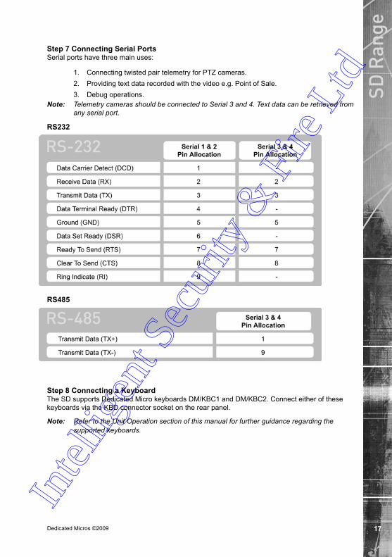
Step Connecting Serial PortsSerial ports have three main uses:
1. Connecting twisted pair telemetry for PTZ cameras.2. Providing text data recorded with the video e.g. Point of Sale.3. Debug operations.
Note: Telemetry cameras should be connected to Serial 3 and 4. Text data can be retrieved from any serial port.
RS
RS
5.16
6.1
Step Connecting a KeyboardThe SD supports Dedicated Micro keyboards DM/KBC1 and DM/KBC2. Connect either of these keyboards via the KBD connector socket on the rear panel.
Note: Refer to the Unit Operation section of this manual for further guidance regarding the supported keyboards.
Intel
ligen
t Sec
urity
& F
ire L
td
Dedicated Micros ©20091
SD R
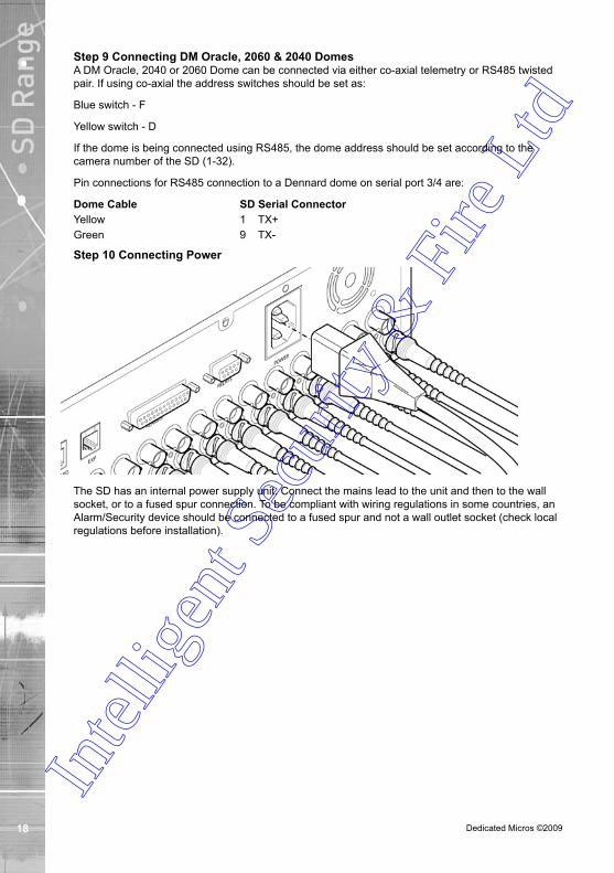
ange Step Connecting DM Oracle, 00 & 00 Domes
A DM Oracle, 2040 or 2060 Dome can be connected via either co-axial telemetry or RS485 twisted pair. If using co-axial the address switches should be set as:
Blue switch - F
Yellow switch - D
If the dome is being connected using RS485, the dome address should be set according to the camera number of the SD (1-32).
Pin connections for RS485 connection to a Dennard dome on serial port 3/4 are:
Dome Cable SD Serial ConnectorYellow 1 TX+Green 9 TX-
Step 10 Connecting Power
The SD has an internal power supply unit. Connect the mains lead to the unit and then to the wall socket, or to a fused spur connection. To be compliant with wiring regulations in some countries, an Alarm/Security device should be connected to a fused spur and not a wall outlet socket (check local regulations before installation).
Intel
ligen
t Sec
urity
& F
ire L
td

Dedicated Micros ©2009 1
SD R
ange
Configuring the UnitThe unit can be configured either on the local monitor or over the network using a PC with Internet Explorer or similar browser. Both have near identical menu interfaces.
Accessing the menus on a local monitor1. The Configuration pages can be displayed on a local monitor (connected to BNC
Connector Mon A on the rear of the unit). When connected, press the MENU button on the IR Remote Control.
Note: If the IR Remote Control does not open the configuration menus, press the DVR button to make sure it is in DVR mode, then press the MENU button again.
Accessing the menus on a PC web browser
Locating the Unit IP addressThe IP address of the unit is required to access the webpages. It can be identified from the configuration menu pages using the local monitor, press the MENU button on the IR Remote Control and navigate to the System Settings->System menu to find the DHCP assigned IP address.
Note: The unit can be installed in a DHCP network environment where an IP address, subnet mask and default gateway will automatically be allocated from the network DHCP Server (DHCP is enabled by default).
Note: If a DNS (Domain Name Server) address is not to be used, it is strongly advised that a fixed IP address be assigned (a DHCP assigned address can change without notification i.e. following power failure). A fixed IP address can be assigned via the Network Settings->Network menu.
For information on locating the unit’s IP address via a PC and serial port connection, refer to Appendix D.
Default DNS AddressIt is recommended that a DNS (Domain Name Server) address be configured. Assigning a recognisable name can help a remote user to locate the unit.
If no System name is allocated to the unit, the default DNS address will be:
machineserialnumber.yourdomain.com
• <machine serial number> is displayed in the System menu page and also on the underside of the unit.• <yourdomain> is the name assigned to your DNS network.
The default DNS address can be renamed via the Network Settings->Network menu. Following renaming, the DNS address will be:
yourname.yourdomain.com
• ’ yourname‘ is the name assigned via the Network menu.
Note: To activate an assigned DNS address, it will be necessary to reboot the unit. The unit can be rebooted via System Settings:Maintain-> Reset.
6.11 Intel
ligen
t Sec
urity
& F
ire L
td

Dedicated Micros ©20090
SD R
ange Accessing the Configuration Webpages
The unit can be configured using the webpages. To access these:
1. Launch Internet Explorer (or similar web browser package).2. Type the URL for the unit (IP or DNS address).
3. The Opening menu page will be displayed.6.13
Intel
ligen
t Sec
urity
& F
ire L
td

Dedicated Micros ©2009 1
SD R
ange
Remote ControlThe IR Remote Control offers all the control functionality required to navigate the menus.
Note: To use the IR Remote Control, the Remote IR Extender mustbe connected to the IR socket on the unit. Not all buttons on the IR Remote Control are relevant for the Unit.
IMPORTANT: To set the time and date on the unit, navigate to System Settings-> Time and Date.
Key Button
Switches the Remote Control to ‘TV’
mode and sends codes understood by common TV sets.
Switches the Remote Control to ‘DVR’ mode. Note the DVR mode is the default mode of operation.
Toggle the speed of PTZ camera
movement (two speeds available).
Use the Zoom button to zoom in/out with a selected camera. Also used to zoom (x2) into Live or Playback images.
This button will change the Zoom Keys
operation to focus or iris functions (when available).
Use this button to cycle through available cameras.
This button should be pressed (followed by a numeric entry) to carry out auxiliary actions on a PTZ camera.
Press the Menu button to enter the Configuration menus.
Press the Exit button to exit the Configuration menus.
Intel
ligen
t Sec
urity
& F
ire L
td
Dedicated Micros ©2009
SD R
ange
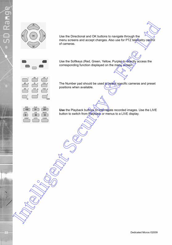
Use the Directional and OK buttons to navigate through the menu screens and accept changes. Also use for PTZ telemetry control of cameras.
Use the Softkeys (Red, Green, Yellow, Purple) to directly access the corresponding function displayed on the menu screen.
The Number pad should be used to select specific cameras and preset positions when available.
Use the Playback buttons to interrogate recorded images. Use the LIVE
button to switch from Playback or menus to a LIVE display.
Intel
ligen
t Sec
urity
& F
ire L
td

Dedicated Micros ©2009
SD R
ange
Main MenuWhen first accessing the unit, the main menu will be displayed. This menu allows access to the Configuration menus, the Viewer menus and also several Download options.
Note: The Download options will only be available if viewing remotely via an IP connection.
Select the Configuration menu tab to access the unit’s Configuration menus. Refer to ‘Navigating the Configuration Menus’ for further guidance.
Select the Viewer menu tab to access the unit’s Viewer function. Refer to ‘Unit Operation’ for information on the numerous Viewer features.
Select the Download menu tab to access the various Download sub-options. Select from:
• Product Manual Select to open an electronic version of the Installation & Operation Guide.
• ObserVer Manual Select to open an electronic version of the NetVu ObserVer User Guide. NetVu ObserVer is a free video management software package from Dedicated Micros that allows users to seamlessly view distributed images from any ‘NetVu Connected’ product.
• NetVu ObserVer Select to download the NetVu ObserVer video management software.
• Java (JRE) Select to download the Java (JRE) software (from the unit). This software is required to successfully view Configuration and Viewer menus remotely.
IMPORTANT: By default, no Usernames and Passwords are required to access any of the various menus. Usernames and Passwords can however be added to regulate access to the Configuration and Viewer menus. Refer to the ‘Console Settings-> User Accounts’ menu for information on establishing Usernames and Passwords.
Intel
ligen
t Sec
urity
& F
ire L
td
Dedicated Micros ©2009
SD R
ange
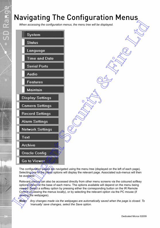
Navigating The Configuration MenusWhen accessing the configuration menus, the menu tree will be displayed.
The configuration pages are navigated using the menu tree (displayed on the left of each page). Selecting one of the menu options will display the relevant page. Associated sub-menus will then be available.
Relevant menus can also be accessed directly from other menu screens via the coloured softkey options shown at the base of each menu. The options available will depend on the menu being viewed. Select a softkey option by pressing either the corresponding button on the IR Remote Control (if viewing the menus locally), or by selecting the relevant option via the PC mouse (if viewing the webpages).
Note: Any changes made via the webpages are automatically saved when the page is closed. To ‘manually’ save changes, select the Save option. Intel
ligen
t Sec
urity
& F
ire L
td

Dedicated Micros ©2009
SD R
angeUsing the IR Remote Control
Press the MENU button to access configuration menus via a connected local monitor. The menu will have a red indicator highlighting the first option. Select a main menu heading to open a drop down list of further sub-options. Press the Down Directional button to highlight the next menu option, press OK to open the highlighted menu.
Press the Right Directional button to highlight the first editable parameter on the screen.
Use the Left/Right/Up/Down Directional buttons to move between fields.
Select OK to start editing a field (the option will be outlined in green).
Use the Up/Down Directional buttons to change the settings within an editable field.
Numeric fields can be edited with the Directional buttons. Use the Up/Down Directional buttons to increase/decrease by an increment of 1, use the Left/Right Directional buttons to increase/decrease by an increment of 10.
Use the OK button to accept a new setting. Use the coloured softkeys to select the accompanying colour option on screen i.e. red button to select the red option. To undo changes made to any menu, select the Refresh (Purple) option.
Entering Alpha-Numeric Data via a Local MonitorNumeric or text data is entered using the on-screen Virtual Keyboard (Arrow Key Editor).
To display the Virtual Keyboard, navigate to the relevant text input box using the Directional buttons and double press the OK button twice on the IR Remote Control. The Virtual Keyboard is displayed.
Use the Directional buttons to move between characters, use the OK button to select a character. Select ‘Submit’ to enter details, press ‘Cancel’ to exit without entering any text.
Alpha-numeric data can also be entered in either upper or lower case format by ‘multi-tapping’ a relevant button. For example, with the cursor located in the text entry window of the Virtual Keyboard, repeatedly tap button ‘1’ to cycle through the following characters: 1,A,a,B,b,C,c,1 etc.
To select one of these characters, simply stop tapping the button when the chosen character is displayed. The cursor will then progress, ready for the next character entry.
Note: A USB Keyboard (not supplied) can be connected via one of the USB ports on the unit. The USB Keyboard can then be used to enter alpha-numeric data via the local menus.
Intel
ligen
t Sec
urity
& F
ire L
td
Dedicated Micros ©2009
SD R
ange Using a USB Mouse or the Webpages
Navigate the menus by clicking the tabs displayed on the left of the menu headings (on the menu tree). The first option is highlighted with a red tab. Select a main menu heading to open a drop down list of further sub-options.
Highlight an editable field by clicking on it directly.
If viewing pages locally, enter alpha numeric data via the Arrow Key Editor (see above). If viewing remotely, enter via the PC keyboard. If available, click on the drop down menus to select settings.
Note: A selected item in the drop down list will appear highlighted.Navigating away from a page (clicking on a different option on the menu tree) will automatically save any changed settings. To undo changes made to any menu, select the Refresh (Purple) option.
Intel
ligen
t Sec
urity
& F
ire L
td

Dedicated Micros ©2009
SD R
ange
System SettingsThe menus under the System Settings heading allow the unit’s core settings to be viewed, changed and the system software upgraded.
The System option displays details about the unit including the IP address, unit serial number, MAC address and software version.
The Unit Status page displays information about the unit’s operating condition, shows how long the unit has been operating and the reason for the last reset. It also shows camera status and displays any failed cameras.
The Alarm Status page shows which contacts are open, which zones are in alarm and which relays are operating.
The Language page allows the system language to be set. The language can also be changed for the current session only.
The Time and Date page allows the unit time and date settings to be adjusted, including setting the timezone.
The Serial Ports page allows each of the four serial ports to be individually configured for one of a range of operations, including EPOS, debug, PPP and telemetry.
The Audio page shows the settings available for each of the audio channels and allows configuration of audio quality.
The Features page allows control of the different features that are available within the software including Email reporting, webcam support and control of the display resolution.
The Maintain page allows the current configuration to be saved, and for previously saved settings to be loaded. It also enables easy upgrade of the system software.
Intel
ligen
t Sec
urity
& F
ire L
td

Dedicated Micros ©2009
SD R
ange
System6.13
This menu shows the general information about the unit including the version of software installed, the unit’s serial number and the allocated DHCP IP address.
Product Descriptor Details the product model. Serial Number Identifies the serial number of the specific unit.PCB Serial Number Displays the PCB (Printed Circuit Board) serial number of the
unit.Product Code Displays a code identifying the unit’s specification.Earliest Recording Displays the date/time of the earliest recording held on the
unit.System Name This field can be edited to allocate a name to the unit. This
is displayed when the unit is accessed via NetVu ObserVer and is sent when transmitting information to a Remote Video Response Centres (RVRC).
Number of Cameras Shows the number of camera channels on the unit.Global PPS Details the Global PPS (Pictures Per Second) recording rate
for all cameras.Video Storage Gbytes Highlights the available video storage capacity in Gigabytes.Video Standard Displays the video standard adopted by the unit i.e. PAL,
NTSC.MAC Address This is the MAC address assigned to the unit.IP Address This is the IP address allocated to the unit.Sub Net This is the subnet of the network where the unit is located. In
tellig
ent S
ecur
ity &
Fire
Ltd

Dedicated Micros ©2009
SD R
angeGateway This is the IP address of the default gateway (router) assigned by
the DHCP server.Software Revision This identifies the version of software the unit is running.Codec Revision This identifies the codec version the unit is running.Webpage Revision This identifies the webpage version the unit is running.PC Apps Revision This identifies the revision archive of the Viewer amd
associated PC Apps software.Boot Software Rev. Displays the infrastructure componentry software revision.
Intel
ligen
t Sec
urity
& F
ire L
td

Dedicated Micros ©20090
SD R
ange
Unit Status This menu details information regarding the status of the unit, notably the total time the unit has been operating and the time since its last reset. Status log information can also be exported via the ‘Export Logs’ option to either a CD/DVD or a USB device.
Time since last reset Details the time since the unit was last reset.Total running time Details the total time the unit has been operational.Reset code The last reset code used is displayed. Restart reason The reason for the last restart is displayed i.e. Controlled
User Reset.Export Log (Blue) Select this option to export log data to an inserted CD/DVD or a
connected USB device. Total Codecs Details the current number of installed codecs.Codecs Installed codecs currently operating as a codec will be highlighted
light green. Hover the cursor over individual buttons to display either ‘On’ or ‘Off’. ‘On’ signifies that the codec is active as a codec.
Framestores Installed codecs currently operating as a framestore will be highlighted light green. Hover the cursor over individual buttons to display either ‘On’ or ‘Off’. ‘On’ signifies that the codec is active as a framestore.
Note: The ‘On’/‘Off’ text will only be displayed if viewing the Unit Status menu remotely over an IP connection.Intel
ligen
t Sec
urity
& F
ire L
td
Dedicated Micros ©2009 1
SD R
angeCameras Connected Those camera channels with cameras connected will be
highlighted light green. Those not in use will appear dark green.Failed Cameras Those camera channels where the connection is deemed to have
failed will be highlighted light green. Those working correctly will appear dark green.
Intel
ligen
t Sec
urity
& F
ire L
td

Dedicated Micros ©2009
SD R
ange
Alarm StatusThis menu details information regarding the status of the unit’s alarm contacts, alarm zones and relay outputs.
Alarm Contacts/Zones/Relay Outputs Alarm Contacts, Alarm Zones and Relay Outputs that are in an ‘active’ state are shown light green. ‘In-active’ ones appear dark green (not illuminated).
Intel
ligen
t Sec
urity
& F
ire L
td

Dedicated Micros ©2009
SD R
ange
LanguageThis menu allows the system language to be set. Changing the System Language will effect all menu pages. If required, the language can also be changed for the current session only.
System Language Select to change the system language setting.Reset (Red) Select to reset the unit.Note: The unit MUST be reset to implement system language changes. Session Language Select to change the language settings for the current
session only.Choose Select to immediately activate session language changes.
Intel
ligen
t Sec
urity
& F
ire L
td

Dedicated Micros ©2009
SD R
ange
Time and Date This menu allows the time and date to be set on the unit. Required timezone information can also be established and the unit time synchronised to that of the PC being used to view the webpages.
System Time The current system time and date is displayed.Current Time Zone Displays the currently selected time zone settings.Time Format As default, the time displayed is in 12 hour format. This can
be changed to 24 hour if required.Date Format As default, the date is entered dd/mm/yy. It can also be
displayed as mm/dd/yy or yy/mm/dd.Set Time Enter a current time for the unit. Set Date Enter a current date for the unit.Time Zone Select the relevant timezone offset from the accompanying drop
down menu. SNTP Server A Simple Network Time Protocol (SNTP) server allows external
devices to connect and set their current date and time settings to that of the SNTP. If required, enter the SNTP server IP address here.
PC Time Displays the system time of the PC currently being used to view the webpages.
Sync Time (Blue) Use this button to synchronise the time of the unit to that of the PC being used to view the webpages.
Note: The PC Time and Sync Time options will only be available if viewing the menu via the webpages.Intel
ligen
t Sec
urity
& F
ire L
td

Dedicated Micros ©2009
SD R
ange
Serial Ports This menu allows configuration of the unit’s Serial ports. Refer to ‘Installing the Unit’ for installation information.
Serial Port These are the four serial ports available.Port Config The serial ports can be configured to specific uses.
Select from: None Switches port off Debug Sets port for serial communications PPP Sets port for Point to Point Protocol Telem Sets port for Telemetry purposes Comm Sets port for Comms purposes EPOS Sets the serial port for connection to an
EPOS (Electronic Point Of Sale) deviceInterface Type Choose the type of serial interface being used. Select from
RS232, RS485 or RS422.Baud/Parity/Data/Stop/Flow Control These options allow the Serial port communication settings to
be configured.Note: When a telemetry protocol is selected, these settings will default to pre-determined values
and should not normally be altered. Protocol This is a drop down list of serial telemetry protocols supported by
the unit.Note: Refer to ‘Appendix E’ for a full list of supported telemetry protocols.In
tellig
ent S
ecur
ity &
Fire
Ltd
Dedicated Micros ©2009
SD R
ange
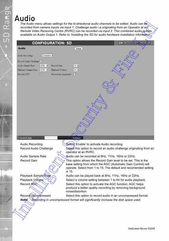
AudioThe Audio menu allows settings for the bi-directional audio channels to be edited. Audio can be recorded from camera inputs via input 1. Challenge audio i.e.originating from an Operator at an Remote Video Receiving Centre (RVRC) can be recorded via input 2. This combined audio is then available on Audio Output 1. Refer to ‘Installing the SD for audio hardware installation information.
Audio Recording Select ‘Enable’ to activate Audio recording.Record Audio Challenge Select this option to record an audio challenge originating from an
operator at an RVRC. Audio Sample Rate Audio can be recorded at 8Hz, 11Hz, 16Hz or 22Hz.Record Gain This option allows the Record Gain level to be set. This is the
base setting from which the AGC (Automatic Gain Control) will operate. Select from 1 to 15. The default and recomended setting is 15.
Playback Sample Rate Audio can be played back at 8Hz, 11Hz, 16Hz or 22Hz.Playback Volume Select a volume setting between 1 to 64 for audio playback.Record AGC Select this option to activate the AGC function. AGC helps
produce a better quality recording by removing background noise/distortion.
Record uncompressed Select this option to record audio in an uncompressed format. Note: Recording in uncompressed format will significantly increase the disk space used.
Intel
ligen
t Sec
urity
& F
ire L
td

Dedicated Micros ©2009
SD R
ange
Features This menu enables the activation of system features such as Email Reporting.
Detected Video Standard The unit automatically detects the video standard being used i.e. PAL/NTSC.
Horizontal/Vertical Edit the resolution settings. This will be the fundamental resolution for the unit.
Text in Images Select this option to activate the Text in Images function, refer to ‘Text-Text In Image’ for more information.
Note: When de-selected here, the ‘Text in Image’ menu will no longer be displayed in the menu tree.
Email Reporting Select this option to activate the Email Reporting function, refer to ‘Network Settings-E-mail’ for more information.
Note: When de-selected here, the ‘Email Reporting’ menu will no longer be displayed in the menu tree.
Remote Reporting Select this option to activate the Remote Reporting function, refer to ‘Network Settings-Remote Reporting’ for more information.
Note: When de-selected here, the ‘Remote Reporting’ menu will no longer be displayed in the menu tree.
Deinterlace mask Select this option to improve display clarity and minimise the comb effect that may be visible when recording high motion scenes in 4CIF mode.
Use Record Profiles for Tx Configures the unit uses the ‘Day Normal’ setting from the Advanced Record Page as the ‘High’ setting on the Live Transmission page to reduce unit Transcoding. In
tellig
ent S
ecur
ity &
Fire
Ltd
Dedicated Micros ©2009
SD R
ange Secondary Web Port If the default port setting for web serving has already been
allocated, it is possible to configure a second port number i.e. the secondary web port can be set to 8000 if the default web port (80) is blocked by the network or firewall.
Unicode Support Select to activate the Unicode function supported by the unit. Unicode is a specification which allows text in any language to be displayed in a consistent and correct manner.
Telem UDP Port Selection Select ‘Automatic’ to enable the unit to select a suitable port for telemetry purposes. Select ‘Default’ to use the default port settings (1025). Select ‘User Defined’ to use settings entered in the ‘Telemetry Port’ option.
Telemetry Port Enter the port settings for telemetry data here. The default setting is 1025.
User Logging Enable this option to activate User Logging. Refer to ‘Appendix C’ for further information regarding the User Logging function.
Comb Filter Enable this option to activate the Comb Filter function. Comb Filter can help improve the fine details of a video signal image by filtering the luminance and chrominance separation process.
Auto Update Web Variables Configures the unit to update all system variables required for an automatic upgrade without requiring confirmation. Do not check this box if you run a customised applet.
Intel
ligen
t Sec
urity
& F
ire L
td

Dedicated Micros ©2009
SD R
ange
MaintainThis menu allows the unit to be reset and a software upgrade to be performed via an inserted CD/DVD or a connected USB device. Current unit settings can also be saved for future use and previously saved settings restored.
ConfigurationDefault (Green) Select to return the unit to its factory default settings.Note: Selecting the Default button will cause the system to reboot.Save (Purple) Select to save current unit settings to the selected media.Restore (Blue) Select to restore previously saved settings from the selected
media.Note: Selecting the Restore button will cause the system to reboot.To/From Select the relevant media device to save to or restore from i.e.
USB or CD/DVD.ServerReset (Red) Select to cycle the power to the unit. IMPORTANT: To upgrade the unit, insert a media device containing relevant software upgrades
and select ‘Reset‘.Note: For the latest software upgrades, please refer to the Dedicated Micros
website: www.dedicatedmicros.com
Intel
ligen
t Sec
urity
& F
ire L
td

Dedicated Micros ©20090
SD R
ange
Display SettingsThe menus under the Display Settings heading allow the unit’s Viewer display settings to be altered and User Account details to be viewed and changed.
The Viewer Defaults page allows the Viewer menu settings to be configured.
The Display page controls how the local monitors present information. They control whether text will be displayed on the Main or Spot monitors, the colour of that text, and how long cameras being displayed in sequence will be shown on screen.
The User Accounts page helps protect configuration procedures by limiting access to specific users via accounts and passwords.
Intel
ligen
t Sec
urity
& F
ire L
td

Dedicated Micros ©2009 1
SD R
ange
Viewer Defaults The units Viewer function allows remote users to simulate local operation over a network. This menu allows configuration of settings for the Viewer function. Refer to ‘Operating The Viewer’ for more information regarding the Viewer.
Default Image Format Images from connected cameras can be displayed in either JPEG or MPEG format.
Default Image Req Images displayed full screen in the Viewer menus can be shown in either High Medium or Low resolution.
Default Multi//Quad Req Images displayed in multiscreen in the Viewer menus can be displayed in either High Medium or Low resolution.
Note:Multi Req not available on 4 input variant.Video Output mode Select the display output that best suits the viewing monitor.
Select from: PAL Default
PAL ReducedNote: It will be necessary to reboot the unit to implement any change to the Video Output Mode.
Intel
ligen
t Sec
urity
& F
ire L
td

Dedicated Micros ©2009
SD R
ange Applet Location The location of the unit’s Viewer menu applet is displayed. The
default location will always be the applet installed on the unit. If accessing multiple units via a remote connection, all can be assigned the same Viewer applet. This will lessen the load time required when accessing different DVRs/Servers. For example, if a local unit and a remote DVR are to be accessed, it is possible to set the Applet location for both DVRs as the local unit. If viewing the unit remotely, Dedicated Micros provide a remote applet located on the Dedicated Micros website (www.dedicatedmicros.com/software_release/index_firmware.php). Due to possible bandwith restrictions on the network the DVR is located, using this remote applet may improve data transfer speeds.
Intel
ligen
t Sec
urity
& F
ire L
td
Dedicated Micros ©2009
SD R
ange
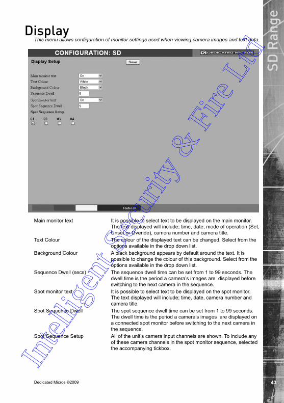
Display This menu allows configuration of monitor settings used when viewing camera images and text data.
Main monitor text It is possible to select text to be displayed on the main monitor. The text displayed will include; time, date, mode of operation (Set, Unset or Overide), camera number and camera title.
Text Colour The colour of the displayed text can be changed. Select from the options available in the drop down list.
Background Colour A black background appears by default around the text. It is possible to change the colour of this background. Select from the options available in the drop down list.
Sequence Dwell (secs) The sequence dwell time can be set from 1 to 99 seconds. The dwell time is the period a camera’s images are displayed before switching to the next camera in the sequence.
Spot monitor text It is possible to select text to be displayed on the spot monitor. The text displayed will include; time, date, camera number and camera title.
Spot Sequence Dwell The spot sequence dwell time can be set from 1 to 99 seconds. The dwell time is the period a camera’s images are displayed on a connected spot monitor before switching to the next camera in the sequence.
Spot Sequence Setup All of the unit’s camera input channels are shown. To include any of these camera channels in the spot monitor sequence, selected the accompanying tickbox.In
tellig
ent S
ecur
ity &
Fire
Ltd

Dedicated Micros ©2009
SD R
ange
User Accounts The unit can protect configuration procedures by limiting access via usernames and passwords.
Account Types The available account types for which users and passwords can be assigned privileges are:
• Admin FTP Assigning username and password requirements for the Admin FTP function will limit access to the unit via an FTP connection.
• Video FTP Assigning username and password requirements for the Video FTP function will limit access to the Video FTP archiving feature (used with DM’s NetVu ObserVer).
. • Telnet Assigning username and password requirements for Telnet connections will limit Telnet access to the unit (Telnet can be used to upgrade the unit).
• Serial Assigning username and password requirements
for Serial connections will limit access via a Serial link.
Intel
ligen
t Sec
urity
& F
ire L
td

Dedicated Micros ©2009
SD R
ange • WebPage Configuration
Assigning WebPage Configuration privileges will limit access to the Configuration menus when viewed remotely. When implemented, the user will be prompted for a username and password before access to the Configuration menus (via the main menu) will be granted.
• Menu Configuration Assigning Menu Configuration access
privileges will limit access to the Configuration menus when viewed locally. When implemented, the user will be prompted for a username and password before access to the Configuration menus (via the main menu) will be granted.
• Local Users Assigning Local Users access privileges
will limit access to the Viewer pages for local users. When implemented, the local user will be prompted for a username and password before access to the Viewer pages (via the main menu) will be granted.
• Remote Users Assigning Remote Users access privileges
will limit access to the Viewer pages for remote users. When implemented, the remote user will be prompted for a username and password before access to the Viewer pages (via the main menu) will be granted.
When granting access privileges to Local and Remote Users, it is possible to limit access to specific cameras. Via the Camera Selection segment of the Add New Account menu, enter those cameras for which access will be permitted. Select the cameras in accordance with the input channel they’re connected to on the rear of the unit. For example, if wanting to allow access to camera 1 to 3 inclusive, enter: 1-3. If wanting to grant access to cameras 1,3 and 6, enter 1,3,6. If no camera data is entered, access will be allowed to all connected cameras in both live and playback modes.
Note: There are no default usernames and passwords for any of the Account Types. If none are assigned, access will be granted to all users and no request for a username and password will be made.
Account List When an Account Type is highlighted, details of users with access will be displayed.
Add Highlight an administration feature i.e. Serial and select ‘Add’. Enter the new User Name and Password. That user’s name will now be displayed in the account list.
Modify/Delete To modify or delete a user’s settings, highlight the user in the list and press the relevant button to Modify or Delete.
Note: If viewing the User Accounts page via a local monitor and navigating with the I.R Remote Control. Press the right directional button from the menu tree to access the Account List.
Intel
ligen
t Sec
urity
& F
ire L
td

Dedicated Micros ©2009
SD R
ange
Camera SettingsThe Camera Settings menus allow configuration of cameras connected to the unit. Refer to the individual menus for further details.
The Camera page allows the quick configuration of all connected local camera channels.
The Camera Setup page allows the colour and contrast settings for each individual camera to be adjusted (with a dynamic preview available).
The Camera Telemetry page enables telemetry capable cameras to be configured.
Intel
ligen
t Sec
urity
& F
ire L
td
Dedicated Micros ©2009
SD R
ange
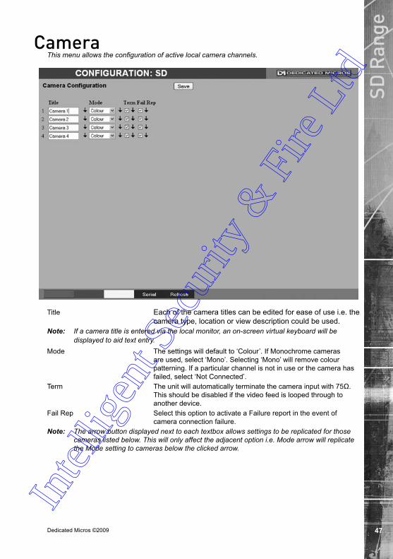
CameraThis menu allows the configuration of active local camera channels.
Title Each of the camera titles can be edited for ease of use i.e. the camera type, location or view description could be used.
Note: If a camera title is entered via the local monitor, an on-screen virtual keyboard will be displayed to aid text entry.
Mode The settings will default to ‘Colour’. If Monochrome cameras are used, select ‘Mono’. Selecting ‘Mono’ will remove colour patterning. If a particular channel is not in use or the camera has failed, select ‘Not Connected’.
Term The unit will automatically terminate the camera input with 75Ω. This should be disabled if the video feed is looped through to another device.
Fail Rep Select this option to activate a Failure report in the event of camera connection failure.
Note: The arrow button displayed next to each textbox allows settings to be replicated for those cameras listed below. This will only affect the adjacent option i.e. Mode arrow will replicate the Mode setting to cameras below the clicked arrow.
Intel
ligen
t Sec
urity
& F
ire L
td

Dedicated Micros ©2009
SD R
ange
Camera Setup This menu allows the colour and contrast settings for each individual camera to be adjusted.
Channel Select a camera channel for review and adjustment. Copy to all Select this option to apply current settings to all
connected cameras.Camera Colour Select a colour value from -8 to +8 via the slidebar or enter a
number directly into the accompanying textbox.Camera Contrast Select a contrast value from -8 to +8 via the slidebar or enter a
number directly into the accompanying textbox.
Intel
ligen
t Sec
urity
& F
ire L
td

Dedicated Micros ©2009
SD R
ange
Camera TelemetryThis menu allows configuration of telemetry capable cameras and the assignment of telemetry protocols.
Cam Lists available camera channels. Title Titles assigned to each camera are displayed.Telemetry If a telemetry capable camera is connected, the appropriate
control protocol should be selected from the accompanying drop down list. Refer to ‘Appendix E’ for details of supported telemetry protocols.
Note: The arrow button displayed next to each textbox allows settings to be replicated for those cameras listed below. This will only affect the adjacent option i.e. Telemetry arrow will replicate the Telemetry setting for cameras below the clicked arrow
Intel
ligen
t Sec
urity
& F
ire L
td

Dedicated Micros ©20090
SD R
ange
Record SettingsThe Record Settings menus allow configuration of the unit’s record functions. Record settings can be configured for normal operation, on alarm, by schedule and for set holiday and weekend periods. Selected video data can be saved and protected. Refer to the individual menus for further details.
The Record page allows the basic Recording settings to be edited.
The Profile Record page allows the recording configuration to be based on specific priorities. The record rate and quality can be customised to respond appropriately to the alarms and time of day. A high degree of control and flexibility is possible using these options.
The Schedule page is used to configure the Timer Function, this enables the unit to automatically be put into set/unset mode at specific times on specific days.
The Holiday and Weekend page enables Set mode to be activated for individual dates i.e. public holidays or weekends.
Intel
ligen
t Sec
urity
& F
ire L
td

Dedicated Micros ©2009 1
SD R
ange
RecordThe unit has a range of pre-defined configurations available. As standard the unit can record at 5pps MPEG4 for up to 14 or 30 days (dependant on model). Alternatively the unit can be configured for 1pps JPEG recording on each camera or for MultiMode operation (note that this will result in the record duration being determined by the time period the unit is in alarm).
Days Recording Displays the record duration possible using the current configuration.
Camera Settings Choose the rate of non alarm recording to be used from the range of preset recording profiles. Select from Normal Rate MPEG4 5pps, Normal Rate JPEG 1pps or MultiMode recording.
Record Duration/Enhance Quality The recording duration can be limited to a set number of days; allowing the recording quality to be enhanced for a shorter storage period.
Intel
ligen
t Sec
urity
& F
ire L
td

Dedicated Micros ©2009
SD R
ange
Profile Record It is possible to set the unit recording configuration based on specific priorities. The MultiMode recording feature offers the ability to set different recording rates, resolutions and compression formats across unset, set and overide modes for each individual camera. By varying the quality, bit rate and file size of recorded images, the MultiMode function enables the recording capabilities of the unit to be greatly increased. The Profile record menu can be accessed in a Simple format or in Advanced mode. The Advanced mode offering greater opportunities to dynamically edit individual cameras recording capabilities.
Simple Record
Menu View Switch to the Advanced Profile Record menu.Days Recording Displays the record duration possible using the current
configuration.Max Collection Resolution Setting the Max Collection Resoluition limits the unit to record
within the following maximum resolutions across all cameras: CIF global pps at a maximum 400pps. 2CIF global pps at a maximum 200pps. 4CIF global pps at a maximum 100pps. Lowering the resoluion settings will significantly lessen the storage
capacity requirements. Note: This option is only available on 4 input variants.Channel Enables selection of a specific camera for editing.Copy To All Select to copy the current profile record settings to all camera
channels.Intel
ligen
t Sec
urity
& F
ire L
td
Dedicated Micros ©2009
SD R
angePre-Trigger (JPEG) Enablng the Pre-Trigger feature will buffer and store alarm
recording prior to an event trigger (in JPEG format). It will use the maximum available memory dependent on other cameras requirements of the buffer space. Select ‘Enable’ to activate.
Note: It is recommended that the Pre-Alarm option in the ‘Alarm Settings-Zone Input’ menu be set to the same value as the Pre-Trigger setting. This will ensure successful playback of high quality Pre-Trigger images. High quality pre-trigger images will only playback properly if review (playback) starts prior to the pre-trigger initiation.
Pre-Trigger Duration (secs) The Pre-Trigger Duration is the maximum possible time that data will be stored prior to an event trigger.
Unset/Set/Override Normal Shows the recording profile used by the camera if no Timer Functions are applied and the camera is operating under Normal (non Event) conditions. Refer to the ‘Schedules’ section for further details.
Unset/Set/Override Event Shows the recording quality that will be used by the camera during an Alarm or Event. Note that Set and Override schedules will be used only when Timed Schedules are applied. Refer to the ‘Schedules’ section for further details.
Comp Select image compression format (MPEG or JPEG).PPS The accompanying dropdown list allows the number of frames
captured per second to be set. The pictures per second (pps) option allows either 6, 5, 2, 1, 0.5,
0.25 or 0.1 pps to be recorded. Pictures can also be recorded at ‘Real Time’ speed, ‘3/4 Real
Time’ or ‘1/2 Real Time’. To disable record, choose the ‘No Record’ option. Select ‘User Defined’ to use settings established in the Advanced
Profile Record menu.Quality The accompanying dropdown list allows the quality of recorded
images to be set. Select from Maximum, Very High, High, Medium, or Low. Select User Defined to use settings established in the Advance Profile Record menu.
Note: The higher the Quality setting, the greater the storage space used.
Intel
ligen
t Sec
urity
& F
ire L
td

Dedicated Micros ©2009
SD R
ange Advanced Record
Menu View Switch to the Simple Profile Record menu.Note: When Advanced Record settings have been changed, it is not possible access the Simple
Record menu until the newly configured Advanced Record settings have been applied. To do this, open the Record menu and select the ‘Save’ option. It will then be possible to return to the Profile Record menu and access Simple Record.
Days Recording Displays the record duration possible using the current configuration.
Max Collection Resolution Setting the Max Collection Resoluition limits the unit to record within the following maximum resolutions across all cameras:
CIF global pps at a maximum 400pps. 2CIF global pps at a maximum 200pps. 4CIF global pps at a maximum 100pps. Lowering the resoluion settings will significantly lessen the storage
capacity requirements. Note: This option is only available on 4 input variants.MPEG4 Compression If using MPEG4 recording, edit the number of P-Frames recorded
before a new I-Frame (keyframe) will be taken.Note: Taking a new I frame once per second when recording above 5pps is recomended. When
the unit rewinds and fast forwards through recorded video, it will access I frames only (and skip P frames). Having too long an interval can make viewing the images in these modes difficult to follow. Note however that too short an interval will reduce the benefits of lower bit rate MPEG4 recording.
Channel Enables selection of a specific camera for editing.Copy To All Select to copy the current profile record settings to all camera
channels.Intel
ligen
t Sec
urity
& F
ire L
td
Dedicated Micros ©2009
SD R
angeJPEG Pre-Trigger Rate (pps) The Pre-Trigger feature will buffer and store alarm recording prior
to an event trigger (in JPEG format). It will use the maximum available memory dependent on other cameras requirements of the buffer space. Enter the record rate (in pps).
Unset/Set/Override Normal Shows the recording profile used by the camera if no Timed Schedules are applied and the camera is operating under Normal (non Event) conditions. Refer to ‘Schedule’ for further information.
Unset/Set/Override Event Shows the recording quality that will be used by the camera during an Alarm or Event. Note that Set and Override schedules will be used only when Timed Schedules are applied. Refer to ‘Schedule’ for further information.
Comp Select image compression format (MPEG or JPEG). Res Select image resolution format (QCIF, CIF, 2CIF or 4CIF). Rate_kbps If MPEG4 is selected, the figure entered here will be the bit rate
allocated. A higher bit rate will provide better quality. MPEG bit rates can be entered within the range of 45-2500K bits/second.
Size If JPEG is selected, the figure entered here will be the size of the JPEG transmitted (in Kbytes). JPEG file sizes can be configured within the range of 5-45Kbytes.
PPS This shows the number of pictures recorded per second.
Intel
ligen
t Sec
urity
& F
ire L
td

Dedicated Micros ©2009
SD R
ange
ScheduleThis menu allows the Timer Function to be configured. The Timer Function enables the unit to automatically be put into set/unset mode at specific times on specific days. This can help reduce unnecessary alarm triggers.
When the unit is in Set or Unset mode, combine with different recording qualities and rates under normal and alarm conditions for a high degree of control in a range of situations.
Note: If Keyswitch is Enabled, the Day Time and Night Time options will not be displayed. The additional Keyswitch options will instead be displayed.
Mode/Title Enables a name to be entered for Unset, Set and Override mode.Current Mode Shows the current timer mode according to the names entered in
the Mode/Title text boxes.Day Time Enter the time (using the 24hr clock) when Unset mode will begin.Night TIme Enter the time (using the 24hr clock) when Set mode will begin.Keyswitch A Keyswitch can be used to switch the recording profile (Unset/
Set), If required, select ‘Enable’ then choose a contact to be used in a specific zone as the Keyswitch.
Note: When the Keyswitch option is set to ‘Enabled’. It is necessary to save (or exit and return to) the menu. The additional Keyswitch options will then be displayed.
Keyswitch-N/O Select whether the Keyswitch is to be normally open (UNSET)Keyswitch EOL Select to configure the Keyswitch for EOL. The End Of Line
(EOL) option enables the Keyswitch to detect any changes in the electronic input resistance. A change outside the expected values will result in a Tamper Alarm (short circuit or open circuit) being detected and the system switching to alarm mode.In
tellig
ent S
ecur
ity &
Fire
Ltd

Dedicated Micros ©2009
SD R
ange
Holiday & WeekendThis menu allows the unit to be automatically switched to Override mode for individual days i.e. public holidays or during a weekend (or any defined period).
Holidays Enter a date and press the Add button. The date will be added to the Holiday list. To delete, highlight and select Delete.
Weekends Select ‘Enable’ to activate the Weekend function. Set mode will now be active for the dates outlined below.
Start Select a Start day and time for Weekend mode.End Select an End day and time for Weekend mode.Note: Weekend mode will remain activate each week until deselected.
Intel
ligen
t Sec
urity
& F
ire L
td

Dedicated Micros ©2009
SD R
ange
Alarm SettingsThe Alarm Settings menus allow configuration of the unit’s alarm functionality. Individual alarm inputs and alarm zones can be configured. Global relays can be activated and the Activity grid set up. Refer to the individual menus for further details.
The Alarm Input page allows configuration of alarm channels. Up to 20 alarm channels are available.
The Zone Input page enables the configuration of alarm zones. Up to 32 separate alarm zones can be created.
The Zone Actions page enables actions such as Go to Preset or Archiving to be allocated to alarm zones. Zones can also be associated with a specific camera. On receipt of an alarm, images from the associated (primary) camera will automatically be displayed in the Viewer menu.
The Activity Setup page allowed activation and configuration of the Activity feature on all video inputs. The Activity feature enables cameras to automatically detect any movement/changes within the video scene. This can trigger a number of operations such as FTP alarm notification or an increase in the recording rate.
The Activity Response page enables configuration of responses following an Activity Detection trigger.
The Global Relays page allows the four onboard relay connections and global relay settings to be configured.
Intel
ligen
t Sec
urity
& F
ire L
td

Dedicated Micros ©2009
SD R
ange
Alarm InputThis menu allows configuration of the alarm settings, refer to ‘Installing the Unit’ for hardware installation guidance.
Number This identifies which input is being configured. The unit supports 20 on-board alarms.
Enabled Each input must be enabled to function. If the input is not enabled and an alarm is received, the unit will not acknowledge the alarm.
N_O (Normally Open Contact) N_O indicates the non-alarm state of the input. Tick the N_O checkbox to set the corresponding input to Normally Open. The alarm will then trigger when the input is closed (shorted). If left as Normally Closed (the default setting), the alarm wil ltrigger when the input is opened.
Note: If EOL alarms are to be used, this option should not be selected i.e. leave set as Normally Closed.
EOL The End Of Line (EOL) option enables the inputs to detect any changes in the electronic input resistance. A change outside the expected values will result in a Tamper Alarm (short circuit or open circuit) being detected and the system switching to alarm mode.
Pulse Ext A pulse extension is used to prevent double triggers on a single alarm. The pulse extension time starts on an alarm trigger. If that contact is triggered again after the first alarm has finished but within the pulse extension, the second trigger will not restart the alarm, but will extend the current alarm duration. Enter the time in seconds for this extension.In
tellig
ent S
ecur
ity &
Fire
Ltd

Dedicated Micros ©20090
SD R
ange Nuisance This is a repetitive detector value. When an alarm is received on
the unit, it will store the alarm time and monitor the number of times the same detector is triggered within an hour period. If the detector is triggered the number of times entered here, the unit will de-activate this detector from triggering an alarm for an hour. The unit will continue to monitor the detector and check how many times it is triggered during this period. If it is again triggered more than the amount set in the nuisance counter, it will remain de-activated for another hour. This will continue until the trigger value falls below the nuisance count setting. To disable this feature, leave the setting as ‘0’.
Stuck Time If any of the alarms/detectors are active for a period longer than specified here, they will automatically be omitted. This time period is set in minutes.
Note: The arrow button displayed next to each textbox allows settings to be replicated for those cameras listed below. This will only affect the adjacent option i.e. Enabled arrow will replicate the Enabled setting to cameras below the clicked arrow.
Intel
ligen
t Sec
urity
& F
ire L
td

Dedicated Micros ©2009 1
SD R
ange
Zone InputThis menu allows the configuration of established alarm zones. A single or multiple trigger can be used to generate an alarm. It is possible to allocate up to 32 alarm zones to carry out a combination of actions. Use these options in conjunction with the Zone Actions menu.
Entry timer This is the number of seconds allowed for the user to enter the zone and disable the alarms. If the alarm is not disabled within this period the alarm will be triggered.
Exit timer This is the number of seconds from the alarm being set within which the user must exit the set zone. If the user is still within the zone after this time period the alarm will be triggered.
Zone An alarm zone can be established to logically groups alarms and initiate actions when an alarm is activated, there are 32 configurable zones.
Title This information is stored along with the relevant images in the database, ensure this has relevance to the alarm zone.
Pre-Alarm sec This is the time period prior to the start of the alarm included with the alarm recording for archive. These images will also be protected from being overwritten.
Note: It is recommended that the Pre-Alarm option be set to the same value as the Pre-Trigger setting in the “Profile Record“ menu. This will ensure successful playback of high quality Pre-Trigger images. High quality pre-trigger images will only playback properly if review (playback) starts prior to the pre-trigger initiation.
Alarm Duration sec This is the minimum time period in seconds (from the start of the alarm) that is protected from being overwritten. This time will include the alarm trigger, the pulse extension and any post alarm recording. It will not include pre-alarm images.
Intel
ligen
t Sec
urity
& F
ire L
td

Dedicated Micros ©2009
SD R
ange Zone Input Rule This determines which input(s) will trigger the zone alarm:
Input This sets an input or system function as the primary alarm trigger. Select from Alarms 1-32, Activity 1-16, Preset 1-16, Disk Low, Disk Full, Panic, Archiving Slow, Archiving Fault, Virtual 1-16, and Keyword Channel 1-32 (which will trigger the Alarm if any or the 32 programmed keywords are detected on the selected channel).
Alarm 24Hr This option can be enabled for alarms that do not require change at any time and are to remain as programmed i.e. Panic Alarm. When this is selected, the Set, Unset and Override options are disabled.
Entry Route Zone This creates deferred alarms along a specified route while the entry time is active. This is in compliance with BS8418 (the British Standard for remote video reporting centres). Diverting from the entry route during the countdown will result in the alarm being triggered immediately. This allows staff entry without triggering an alarm prior to switching the system to Set mode.
Exit route Zone This creates deferred alarms along a specified route while the exit time is active. This is in compliance with BS8418 (the British Standard for remote video reporting centres). Diverting from the exit route during the countdown will result in the alarm being triggered immediately. This allows staff to exit without triggering an alarm.
Exit Terminator This will trigger the exit timer if the system is set. A countdown timer will automatically start when the alarm is activated and ensure the alarm system is not activated by other specified alarm triggers for the Set time i.e. allowing a Guard to exit a building.
Entry Initiator This will trigger the entry timer if the system is set. A countdown timer will automatically start when the ‘primary’ alarm trigger i.e. front door, is actioned. This ensures the alarm system is not activated by other specified alarm triggers for the set time
Enable in Unset Each alarm can be configured to be active when the unit is in a specific operation mode. Enable this for the zone alarm to be active in Unset operation mode.
Enable in Set Each alarm can be configured to be active when the unit is in a specific operation mode. Enable this for the zone alarm to be active in Set operation mode.
Enable in Override Each alarm can be configured to be active when the unit is in a specific operation mode. Enable this for the zone alarm to be active in Override operation mode.
Intel
ligen
t Sec
urity
& F
ire L
td
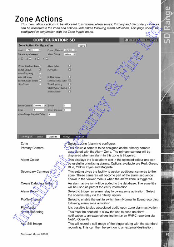
Dedicated Micros ©2009
SD R
ange
Zone ActionsThis menu allows actions to be allocated to individual alarm zones; Primary and Secondary cameras can be allocated to the zone and actions undertaken following alarm activation. This page should be configured in conjunction with the Zone Inputs menu.
Zone Select a zone (alarm) to configure.Primary Camera This allows a camera to be assigned as the primary camera
associated with the Alarm Zone. The primary camera will be displayed when an alarm in this zone is triggered.
Alarm Colour This displays the local alarm text in the selected colour and can be useful in prioritising alarms. Options available are Red, Green, Blue, Yellow, Cyan and Magenta.
Secondary Cameras This setting gives the facility to assign additional cameras to the zone. These cameras will become part of the alarm sequence shown in the Viewer menus when the alarm zone is triggered.
Create Database Entry An alarm activation will be added to the database. The zone title will be used as part of the entry information.
Alarm Relay Select to trigger an alarm relay folowing zone activation. Select the specific relay via the ‘Relay’ option.
Profile Change Select to enable the unit to switch from Normal to Event recording following alarm zone activation.
Play Audio It is possible to play associated audio upon zone alarm activation.Alarm Reporting This must be enabled to allow the unit to send an alarm
notification to an external destination i.e an RVRC reporting via NetVu ObserVer
Add Still Image This will record a still image of the trigger along with the standard recording. This can then be sent on to an external destination.
Intel
ligen
t Sec
urity
& F
ire L
td

Dedicated Micros ©2009
SD R
ange Email Image If this option is selected, a JPEG will be added to the reporting
email (if Email Reporting is selected).Protect alarm Images Alarm images can automatically be protected from
being overwritten.Switch Spot Monitor Select to display the alarm zone Primary camera on the Spot
Monitor.Goto Preset It is possible to action a camera to automatically be sent to a
preset position when an alarm is triggered. Email Reporting The unit can send an email when an alarm is detected, refer to
‘Network-E-mail’ for more information.VMD/Activity Inhibit Select to inhibit (ignore) the VMD/Activity detection feature. Refer
to ‘Activity Setup’ for more information.Enable Buzzer Select to activate the unit’s internal buzzer upon alarm receipt.Preset Camera The preset camera is the camera which will be sent to a
designated preset position upon alarm activation.Preset Enter the preset position number for the selected camera here,
refer to ‘Unit Operation-PTZ Program’ for more information on establishing camera preset positions.
Relay Select an onboard or external relay to automatically close on receipt of an alarm.
Relay Duration Enter (in seconds) how long the relay is to remain closed.Alarm Image Snapshot Delay This figure allows a delay to be introduced before an alarm
snapshot is taken. This is used when the alarm relates to a PTZ camera which has to travel to a preset position.
Intel
ligen
t Sec
urity
& F
ire L
td

Dedicated Micros ©2009
SD R
ange
Activity SetupThe unit supports Activity Detection on all video inputs. It enables cameras to automatically detect any movement/changes within the video scene; this can trigger a number of operations such as FTP alarm notification and an increase in recording rate. A still image of the selected camera will be shown in the Grid Editor screen. To establish an Activity zone, edit the cells displayed across the image. This option should be used in conjunction with the Zone Inputs and Zone Actions menus.
Global Activity Mode Three options are available for Activity activation (specifically in relation to a PTZ camera). Selecting ‘Active while at Preset 1’ will result in Activity mode functioning only when the camera is at preset position 1. Select ‘Active while camera not in motion’ for Activity mode to function only when the camera is still. Select ‘Always Active’ for Activity mode to be in constant operation.
Activity Channel This is a drop down list of the video inputs on the unit, selecting an input will display images from the corresponding video source.
Grid Editor Use the Grid Editor by placing cells in areas of the camera view where movement will trigger an alarm. To enter cells navigate across the image via the Directional buttons of the I.R Remote Control). if viewing on a local monitor place a cell by pressing the OK button. If viewing via the webpages, use the mouse to navigate across the image, use the left mouse button to place a cell.
Reload Img (Red) This option will update the still image displayed in the Grid Editor.Set All (Green) This option will insert a default square of 16 x 16 cells across the
displayed video image.Clear All (Yellow) This option will clear all entered cells.
Intel
ligen
t Sec
urity
& F
ire L
td
Dedicated Micros ©2009
SD R
ange Edit Mode Leave as ‘Normal’. Different Edit Mode functions will be added
following future development.Edit Action Select ‘Invert’ to change the current grid state i.e. Clear to Set.
Select ‘Clear’ to remove grids or select ‘Set’ to add grids. Activity Detection Select ‘Enabled’ to activate the Activity Detection feature.Activity Sensitivity This option allows the sensitivity setting to be established for the
activity grid being configured. There are five settings to choose from: Indoor High, Indoor Low, Outdoor High, Outdoor Low, Very Low.
Intel
ligen
t Sec
urity
& F
ire L
td

Dedicated Micros ©2009
SD R
ange
Activity Response SetupThis menu enables response configuration following activity trigger on a selected camera channel.
Channel Select the camera input for configuration from the drop down list.Activity To Trigger Following Activity activation, select ‘Simple Response’ to trigger
specific chosen responses. Refer to ‘Activity Response Setup’ for more information. Select ‘Zone’ to apply the Zone Input rules as configured in the Zone Input menu. Refer to ‘Zone Input’ for more information.
Copy To All Select to copy the current Activity Response settings to all camera channels.
Create Database Entry When selected, an alarm entry will be added to the Event database.
Profile Change Select to enable the unit to switch from Normal to Event recording following alarm activation.
Alarm Reporting This must be enabled for the unit to automatically connect on alarm.
Alarm 24Hr This will ensure that Activity Detection is permanently enabled on this camera channel.
Protect Alarm Images Select to automatically protect alarm images from being overwritten.
Switch Spot Monitor Enable this option to display alarm activated cameras on the connected Spot Monitor.
Enable in Day This will enable Activity Detection when the unit is in Day (Unset) operation mode.In
tellig
ent S
ecur
ity &
Fire
Ltd
Dedicated Micros ©2009
SD R
ange Enable in Night This will enable Activity Detection when the unit is in Night (Set)
operation mode.Enable in Weekend This will enable Activity Detection when the unit is in Weekend
(Override) operation mode.
Intel
ligen
t Sec
urity
& F
ire L
td

Dedicated Micros ©2009
SD R
ange
Global ActionsThis menu details how to configure the default relay actions supported on the unit. The unit supports four onboard relay connections and global relay settings. These global relays can be triggered under specific conditions i.e. on receipt of any alarm or any notification of Activity Detection.
Image Protection Period Select a time period (in days) that images associated with an alarm will be protected from deletion.
Alarm Display Mode When a relay has been triggered, the primary camera associated with that relay can immediately be displayed on the local monitor. Select ‘Jump To Primary Camera’ from the drop down list to activate this function.
Revert Display Mode after Alarm Enable this setting to make the unit return to the view displayed before the alarm activation.
Alarm Display Alert Enable this setting to display an alarm text alert in the colour specified in ‘Alarm Colour’ in the Zone Actions Menu.
Alarm (Relay 1) Select this option to establish any alarm trigger as a Global Relay. Therefore the relay will close when an alarm is received on any of the alarm inputs.
Activity (Relay 2) Select this option to establish any Activity Detection trigger as a Global Relay. Therefore the relay will close when Activity is identified on any of the camera inputs.
Intel
ligen
t Sec
urity
& F
ire L
td

Dedicated Micros ©20090
SD R
ange Camera Fail (Relay 3) Select this option to establish any camera fail trigger as a Global
Relay. Therefore the relay will close when there is notification on the system that any of the enabled video inputs has camera failure (no 1V pk-to-pk signal).
System Set (Relay 4) When selected, the unit will automatically switch to Set mode following relay activation.
Intel
ligen
t Sec
urity
& F
ire L
td

Dedicated Micros ©2009 1
SD R
ange
Network SettingsThe Network Settings menus allow configuration of the unit’s network functionality. Key network settings can be established such as ‘fixing’ the unit’s IP address and maximum transmission rate. E-mail, remote reporting on alarm and FTP download can also be configured. Refer to the individual menus for further details.
The Network Settings page allows configuration of the unit’s network connections such as the name assigned to the unit and its IP address.
The Live Transmission page enables JPEG and MPEG profiles to be created for transmitting images via a High, Medium or Low quality network connections to any viewing software or to another unit using this one as an IP source..
The Email page allows configuration of the Email feature. The unit can automatically transmit an e-mail to an SMTP Server following an event i.e. on receipt of an alarm or a camera failure notice.
The Remote Reporting page allows a Remote Video Receiving Centre’s (RVRC) configuration details to be entered. The RVRC will then be contacted following a selected event occurring i.e. reported alarm or camera failure.
Intel
ligen
t Sec
urity
& F
ire L
td
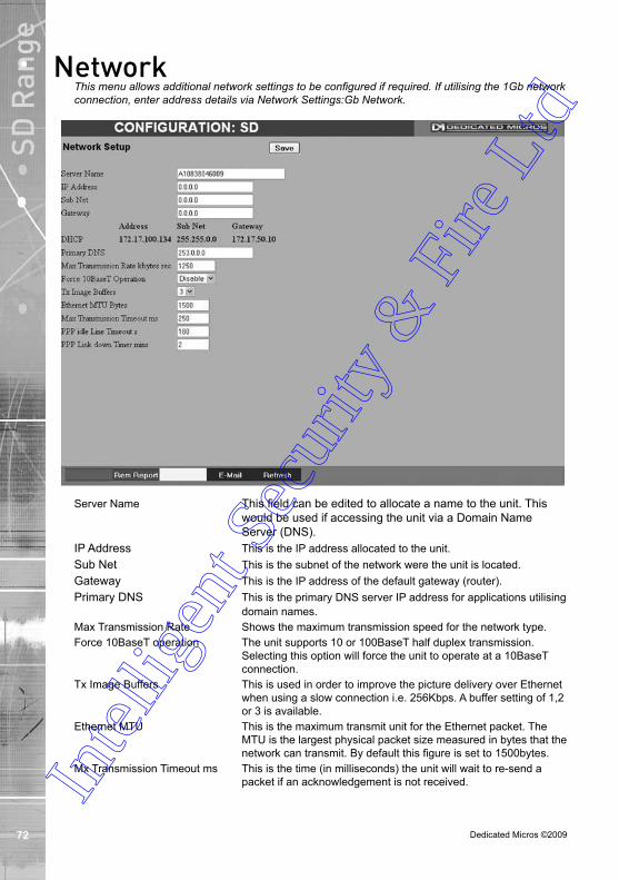
Dedicated Micros ©2009
SD R
ange
NetworkThis menu allows additional network settings to be configured if required. If utilising the 1Gb network connection, enter address details via Network Settings:Gb Network.
Server Name This field can be edited to allocate a name to the unit. This would be used if accessing the unit via a Domain Name Server (DNS).
IP Address This is the IP address allocated to the unit.Sub Net This is the subnet of the network were the unit is located. Gateway This is the IP address of the default gateway (router).Primary DNS This is the primary DNS server IP address for applications utilising
domain names.Max Transmission Rate Shows the maximum transmission speed for the network type.Force 10BaseT operation The unit supports 10 or 100BaseT half duplex transmission.
Selecting this option will force the unit to operate at a 10BaseT connection.
Tx Image Buffers This is used in order to improve the picture delivery over Ethernet when using a slow connection i.e. 256Kbps. A buffer setting of 1,2 or 3 is available.
Ethernet MTU This is the maximum transmit unit for the Ethernet packet. The MTU is the largest physical packet size measured in bytes that the network can transmit. By default this figure is set to 1500bytes.
Mx Transmission Timeout ms This is the time (in milliseconds) the unit will wait to re-send a packet if an acknowledgement is not received. In
tellig
ent S
ecur
ity &
Fire
Ltd
Dedicated Micros ©2009
SD R
angePPP Idle Line Timeout s This is the time (in seconds) the unit will wait before disconnecting
the PPP (Point to Point Protocol) link if data has not been transmitted or received.
PPP Link Down Timer mins If for any reason the PPP connection is lost, this is the time (in minutes) before the unit will be forced to drop the PPP connection.
Intel
ligen
t Sec
urity
& F
ire L
td

Dedicated Micros ©2009
SD R
ange
Live TransmissionsThe unit transmits live images using JPEG or MPEG formats. The NetVu Connected remote viewing software will use the settings configured on this page as the defaults for JPEG & MPEG; High, Medium and Low settings.
High LAN/Medium WAN/Low VLBR This shows the transmission settings configured for a High quality LAN (Local Area Network) connection, Medium quality WAN (Wide Area Network) connection or a Low quality VLBR (Very Low Bit Rate connection).
Comp Settings can be established for JPEG and MPEG compression.Res For MPEG and JPEG transmission, select image resolution
settings (4CIF, 2CIF, CIF or QCIF). Size_rate For JPEG, the figure entered will be the size of the JPEG
transmitted (in Kbytes). For MPEG4 the figure will be the bit rate allocated. A higher rate will provide better quality picture display. JPEG file sizes can be configured in the range of 5-45Kbytes and MPEG bit rates in the range of 45-2500Kbits/second.
ms This shows the number of pictures transmitted per millisecond. For JPEG, the actual images transmitted will depend on the bandwith of the link, increasing the pictures sent per millisecond may introduce time lag if bandwith is not sufficient. On MPEG transmission, increasing the pictures sent will also reduce the quality of the images (as more images are transmitted for the defined bit rate).
MPEG Comp Type Select whether transmitted MPEG4 images are sent as RAW data or in GOV (Group of Video) format. RAW mode transmits a single I frame and then a sequence of P frames (until a change in transmission is detected). GOV mode sends I and P frames in a standard format i.e. I to P frame ratio as set by the record parameters.
Intel
ligen
t Sec
urity
& F
ire L
td
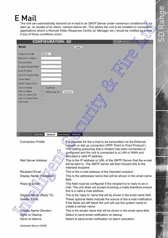
Dedicated Micros ©2009
SD R
ange
E MailThe unit can automatically transmit an e-mail to an SMTP Server under numerous conditions i.e. on start up, on receipt of an alarm, camera failure etc. This allows the unit to be installed in unmanned applications where a Remote Video Response Centre (or Manager etc.) would be notified by e-mail if any of these conditions occur.
Connection Profile It is possible for the e-mail to be transmitted via the Ethernet network or dial up connection (PPP ‘Point to Point Protocol’). This setting presumes that a modem has been connected or configured and the unit is connected to a LAN or WAN and allocated a valid IP address.
Mail Server Address This is the IP address or URL of the SMTP Server that the e-mail will be sent to. The SMTP server will then forward this to the intended recipient.
Recipient Email This is the e-mail address of the intended recipient.Display Name (Recipient) This is the addressee name that will be shown in the email name
field.Reply to Email This field must be configured if the recipient is to reply to an e-
mail. The unit does not accept incoming e-mails therefore ensure this is a valid e-mail address.
Display Name (Reply To) This is the ‘reply to’ name that will be shown in the email name field. Sender Email These optional fields indicate the source of the e-mail notification.
If the fields are left blank the unit will use the system name to create a sender name.
Display Name (Sender) This is the sender name that will be shown in the email name field.Send on Startup Select to send email notification on startup.Send on Alarms Select to send email notification on alarm activation.In
tellig
ent S
ecur
ity &
Fire
Ltd

Dedicated Micros ©2009
SD R
ange Send on Camera Fail Select to send email notification on camera fail.
Send on Activity Event Select to send email notification on activation of the Activity Detection feature.
Send Image Select to send accompanying image from supporting primary camera.
Log Email Select to log every e-mail transaction that the unit issues.Email Image Res Select resolution settings for images sent as ‘thumbnail’
attachments. Choose from: Thumbnail, LO (low res), MED (medium res) and HI (high res).
Intel
ligen
t Sec
urity
& F
ire L
td

Dedicated Micros ©2009
SD R
ange
Remote ReportingThis menu details the configuration requirements for the unit to report to a Remote Video Receiving Centre (RVRC) following alarm activation.
Note: This menu will only be displayed if ‘Remote Reporting’ is selected in the System Settings->Features menu.
Primary Hostname This is the IP address or URL of the initial host that the unit will transmit an alarm message to.
Primary Dial Profile It is possible for the alarm message to be transmitted via the Ethernet network or a dial up connection.
Secondary Hostname If the unit is unable to contact the primary host, an alternative route can be identified via a secondary host. If there is only one alarm receiving IP address, you must enter the details in both the primary and secondary connection settings.
Secondary Dial Profile It is possible to select a separate dial profile for the secondary host.
Public (NAT) IP Address This is the public IP (or domain name) for a unit connected to the Internet via a NAT Router or Firewall. This field should be left blank if NAT is not used e.g. a private network.
Video Server Port This field allows the RVRC to connect to the unit through a router that is using port forwarding e.g. if the video server does not appear on port 80 (HTTP), to the external network. Enter the port number used for fowarding here if required.
Alarm Server ref. ID This is the reference name/ID that will be presented to the RVRC viewing application. It should therefore have some significance to the Operator.
Remote Alarm Reporting This must be enabled for the unit to automatically connect on alarm.
Intel
ligen
t Sec
urity
& F
ire L
td

Dedicated Micros ©2009
SD R
ange Remote Cam Fail Reporting Enabling this option ensures the unit reports camera failure on
any of the inputs to the RVRC.Remote Startup Reporting This will send an alarm report when the unit starts up. Any system
resets will be identified.ARC Ping Enabled Should the modem/router at the Alarm Receiving Centre be dormant,
the unit will ‘Ping’ the ARC prior to sending reporting data.Alarm Responder Port This specifies the network port number used for reporting to the
alarm server. In normal circumstances this should be left at the default value (23).
Dial Retry Time (secs) If the initial connection attempt fails, the unit will wait for the specified time period (in seconds) before attempting to re-connect.
Dial Count This identifies the number of times the unit will attempt to connect after a failed attempt. A setting of ‘0’ means no limit and the unit will continue to try and connect until successful.
Intel
ligen
t Sec
urity
& F
ire L
td

Dedicated Micros ©2009
SD R
ange
TextThe Text menus allow configuration of the unit’s text in image and keywords functionality. Refer to the individual menus for further details.
The Text In Image page allows the unit to integrate text data with recorded images i.e. a cash register with a camera positioned at the point of sale.
The Keyword page can be used in conjunction with the Text in Image function. Keywords can be entered, which when detected, will trigger an alarm. Up to 30 keywords can be created.
Intel
ligen
t Sec
urity
& F
ire L
td

Dedicated Micros ©20090
SD R
ange
Text In Image It is possible to integrate the unit into a system were text information can be stored with relevant images for review. This would be most useful in a Retail or Finance application were text data originating from a cash register could be displayed in real time with the video images of the same Point of Sale.
Note: This menu will only be displayed if ‘Text in Image’ is selected in the System Settings->Features menu.
Recorded lines per frame This controls how many lines of text are stored on the server, and not how many are displayed on screen. This allows more data to be saved than is shown.
Text Timeout This setting controls how long, in seconds, the text is shown onscreen (selecting 0 will show the text indefinitely).
Channel Select the camera input for configuration from the drop down list.Copy To All Select to copy the current text in image settings to all
camera channels.Text Port Type Select the input source for Text in Image data. Select ‘Off’ to
switch the function off, select ‘Network to use the unit’s Network port or ‘Serial’ to use one of the unit’s serial ports (see ‘Port’ below).
Port All serial ports on the unit support the option for Text In Image. For serial transmission ensure one of the serial ports is configured appropriately, refer to System Settings->Serial Ports’. Select the configured port from the drop down list.
Text Filter Select the text filter option from the drop down list. The options are: Plain Text (default), RAW, EPSON, Laserjet, DM POS Receipt, DM POS Journal, TVC-1066
Intel
ligen
t Sec
urity
& F
ire L
td

Dedicated Micros ©2009 1
SD R
angeLine length This identifies the length of the lines that will be stored with the
image. The default setting is 20 characters i.e. typically full screen.
Number Visible Lines To enable the text information to be viewed successfully, it is necessary to establish how many lines of text will be visible on screen.
Background Colour A black background box appears by default around the text. It is possible to change the colour of this box. Select from the drop down list.
Text Colour The colour of the displayed text can be changed. Select from the drop down list.
Enable Keywords This enables or disables the Keyword feature, allowing the unit to treat certain pre-programmed words received via the text stream as event triggers.Refer to ‘Keywords’ for guidance on creating Keyword triggers.
Keywords pulse extension This time period allows multiple instances of a word received within a period of time to be treated as a single event (i.e. if a configured Keyword is detected again within the first Keyword’s pulse extension period, the second (and following) occurrences of the word will be ignored).
Intel
ligen
t Sec
urity
& F
ire L
td
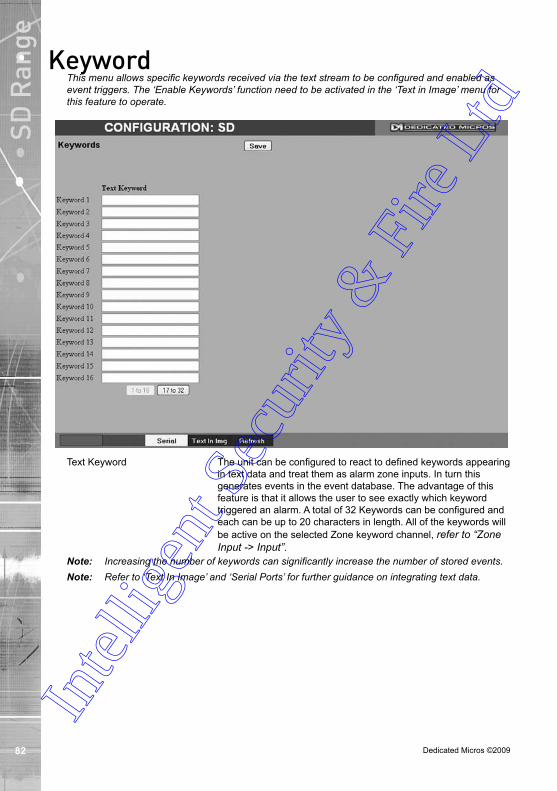
Dedicated Micros ©2009
SD R
ange
KeywordThis menu allows specific keywords received via the text stream to be configured and enabled as event triggers. The ‘Enable Keywords’ function need to be activated in the ‘Text in Image’ menu for this feature to operate.
Text Keyword The unit can be configured to react to defined keywords appearing in text data and treat them as alarm zone inputs. In turn this generates events in the event database. The advantage of this feature is that it allows the user to see exactly which keyword triggered an alarm. A total of 32 Keywords can be configured and each can be up to 20 characters in length. All of the keywords will be active on the selected Zone keyword channel, refer to “Zone Input -> Input”.
Note: Increasing the number of keywords can significantly increase the number of stored events. Note: Refer to ‘Text In Image’ and ‘Serial Ports’ for further guidance on integrating text data.
Intel
ligen
t Sec
urity
& F
ire L
td

Dedicated Micros ©2009
SD R
ange
ArchiveThis menu allows Event database information to be downloaded to an inserted DVD/CD or connected USB media device.
Archive Media Select to archive to either a DVD/CD or USB media device.Start Date Enter a start date for the event download.Start Time Enter a start time for the event download.End Date Enter an end date for the event download. End Time Enter an end time for the event download.Viewer When selected, the unit will add a Viewer program to the archive.
It is recommended that this option be selected as it will ensure the downloaded video images can always be successfully viewed.
Check Media button Selecting this option will display the space required (in megabytes) for the chosen event period to be fully downloaded. The space currently available on the CD/DVD or USB device is also shown.
Archive Space Required Space required for archive download.Archive Space Available Space currently available on CD/DVD or USB device.Archive button Select this button to begin the Archive process.Status During Archiving, status messages will be displayed detailing the
archive process.
Intel
ligen
t Sec
urity
& F
ire L
td

Dedicated Micros ©2009
SD R
ange
Oracle Dome ConfigurationIf a camera channel has a Dedicated Micros Oracle dome camera connected, the Oracle Configuration menus can be used to view settings and establish Presets, Patrols and Privacy Masks. Refer to individual menus for further details.
The Status page details fundamental information regarding the status of the Oracle Dome i.e. the model type and the version of software/firmware installed.
The Presets page allows Preset positions to be configured and stored.
The Sectors page enables the cameras 360 degree field of view to be effectively split into 32 segments. These segments can be named and displayed via the On Screen Display (OSD).
The Patrols page allows camera patrol sequences to be established and configured. The Patrol feature uses established preset positions to automatically pan, tilt and zoom the camera in the selected sequence.
The Privacy Masks page allows privacy masking to be established and configured. The Privacy Mask feature can be used to ‘blank out’ sensitive or private areas which appear in the cameras field of view.
The OSD Settings page allows the Oracle Dome OSD (On Screen Display) information to be configured. This text will accompany displayed camera images in the Viewer menus.
The Camera Settings page enables features such as white balance and shutter speed to be configured.
The Event Settings page allows actions to be established and configured for the Oracle Dome camera following an alarm. A Home position can be established and the delay time set for what period of inactivity is required before the camera will be sent to its home position.
Intel
ligen
t Sec
urity
& F
ire L
td

Dedicated Micros ©2009
SD R
ange
StatusThis menu details information regarding the status of the Oracle Dome, notably the model type, current temperature and the version of software/firmware installed.
Camera Select a camera channel. The menu will only display successfully if the chosen camera channel has an Oracle Dome camera connected.
IMPORTANT: All subsequent Oracle Configuration menus will relate to the camera selected here. Camera selection is only possible via this Status menu.
Camera Title Title assigned to the selected camera channel.Dome Model Details the product model.Dome Serial Number Identifies the serial number of the specific camera.Total Time On Details the operational life time of the camera to date.Total Time Active Details the total time the unit has been active (in motion).Time Since Restart Details the time since the camera was last reset.Current Temp Details the current temperature of the camera unit.Max Temp Details the maximum temperature the camera unit has reached.Min Temp Details the minimum temperature the camera unit has reached.Fan 1 Status Details the operational status of installed Fan 1.Fan 2 Status Details the operational status of installed Fan 2.Relay State Details the operational status of the camera unit’s relay. Software Version This identifies the version of software the camera unit is running.Firmware Version This identifies the version of firmware the camera unit is running.Bootloader Version This identifies the bootloader version of the camera unit
is running. Intel
ligen
t Sec
urity
& F
ire L
td

Dedicated Micros ©2009
SD R
ange
PresetsThis menu allows Preset positions to be configured and stored for the Oracle Dome camera.
Camera ID Selected camera channel.Camera Title Title assigned to the selected camera channel.Preset Select a preset number (1 to 100).Preset Name Enter a recognisable name for the Preset (up to a maximum of
25 characters).+ (Red) Use the + button to zoom the camera view IN.- (Blue) Use the - button to zoom the camera view OUT.Navigation Buttons Use the four navigation buttons to position the camera view.Save (Grey) Select to save the entered preset title to the unit and the Oracle
Dome camera memory. Store Preset (Red) Select this button to store the current preset position to the Oracle
Dome camera’s memory. Goto Preset (Green) Select this button to immediately send the camera to the currently
stored preset position. Delete Preset (Yellow) Select this button to delete the currently displayed preset
configuration.
Intel
ligen
t Sec
urity
& F
ire L
td

Dedicated Micros ©2009
SD R
ange
Sectors This menu allows the Oracle Dome cameras 360 degree field of view to be split into 32 segments. These segments can be named and set to accompany the displayed camera image via the OSD menu. They can be used to aid an Operator in quickly identifying the current camera position.
Camera ID Selected camera channel.Camera Title This is the title assigned to the selected camera channel.Sector Select from sector 1-32.Sector Name Enter a name for the selected sector (up to a maximum of
25 characters).+ (Red) Use the + button to zoom the camera view IN.- (Blue) Use the - button to zoom the camera view OUT.Navigation Buttons Use the four navigation buttons to position the camera view.
Intel
ligen
t Sec
urity
& F
ire L
td

Dedicated Micros ©2009
SD R
ange
PatrolsThis menu allows camera patrol sequences to be established and configured for the Oracle Dome camera. The Patrol feature utilises established preset positions to automatically pan, tilt and zoom the camera in the selected sequence.
Camera Selected camera channel.Camera Title Title assigned to the selected camera channel.Patrol Up to four Patrol sequences can be established.Patrol Name Enter a recognisable name for the Patrol.1-32 Up to 32 individual positioning manoeuvres can be added to a
Patrol.Note: Selecting one of the 1-32 buttons will send the camera to that Preset position.Preset Select a pre-established Preset.Speed Select the Speed the Patrol will progress to the next Preset
position (the speed can be set as a percentage of maximum capability).
Dwell Select the Dwell time (in seconds) the Patrol will remain at this Preset position.
Save (Grey) Select to store the preset sequence to the unit and the Oracle Dome camera memory.
Play (Red) Select to activate (play) the current patrol sequence.Intel
ligen
t Sec
urity
& F
ire L
td

Dedicated Micros ©2009
SD R
ange
Privacy MasksThis menu allows Privacy Masks to be established and configured for the Oracle Dome camera. The Privacy Mask feature can be used to ‘blank out’ sensitive or private areas which appear in the cameras field of view.
Camera Selected camera channel.Camera Title Title assigned to the selected camera channel.Mask Up to 24 separate masked areas can be created.Mask Colour The colour of the mask can be selected from the drop down list.
The default is black.Note: Select ‘Start New’ (Red) to begin creation of a privacy area. A black rectangle will then be
displayed superimposed across the camera view. It is recommended that the camera be navigated to the exact centre of the area requiring the privacy mask before pressing the ‘Start New’ button.
+ (Red) Use the + button to zoom the camera view IN.- (Blue) Use the - button to zoom the camera view OUT.Navigation Buttons Use the four navigation buttons to position the camera view.Note: When ‘Start New’ has been selected, the +/- and Navigation buttons can be used to set the
size and shape of the Privacy Mask. Save (Grey) Select to store the mask colour.Start New (Red) Select this option to begin creation of privacy mask.Finish New (Green) Select this option to finish creation of privacy mask.Show (Yellow) Select this option to show camera view with existing privacy mask
displayed.Delete (Blue) Select this option to delete the currently displayed privacy mask.In
tellig
ent S
ecur
ity &
Fire
Ltd

Dedicated Micros ©20090
SD R
ange
OSD SettingsThis menu allows the Oracle Dome OSD (On Screen Display) information to be configured. This text will accompany displayed camera images in the Viewer and on a local monitor.
Preset Title Position Select desired position to locate the Preset Title information.Sector Title Position Select desired position to locate the Sector Title information.PTZ Display Position Select desired position to locate the PTZ Display information.Alarm Name Position Select desired position to locate the Alarm Name Position
information. For all above functions, the available positions are:
Top Left, Top Right, Bottom Left, Bottom Right and Off (No information displayed). All options are then split into three further sections; 1,2 and 3. This relates to the display line i.e. Top Left 1 would be the very top line, Top Left 2 would be the line below etc. This enables information to be ‘stacked’ in one segment of the screen.
Engineer Display Toggle to switch the Engineer Display text On/Off. This function is intended for future development.
Save (Grey) Select to store OSD Settings to the unit and the Oracle Dome camera memory.
Intel
ligen
t Sec
urity
& F
ire L
td

Dedicated Micros ©2009 1
SD R
ange
Camera SettingsThis menu allows settings for the Oracle Dome camera to be established and configured.
Camera Selected camera channel.Camera Title Title assigned to the selected camera channel.Backlight Comp Select to activate Backlight Compensation. This feature
compensates for back-lit scenes by enhancing objects which would previously have been in silhouette.
Auto Slow Shutter The Oracle Domes auto slow shutter feature enables the camera to automatically decrease the shutter speed in low light settings to help maintain quality of displayed images.
Auto Focus The Oracle Domes Auto Focus feature enables the camera to best focus on its current view. Select to activate.
Auto Flip When the Oracle Domes Auto Flip feature is activated, it will rotate a camera 180 degrees when it reaches its maximum upper or lower extremity i.e pointing directly upwards or downwards. This enables a camera to continue a tilt manoeuvre i.e. if tilting in an upwards direction, when the camera is pointing directly up, it will rotate 180 degrees and begin tilting down. If unselected, a camera will stop when it reaches its maximum upper or lower extremity.
HyperD Mode If the connected Oracle Dome camera is part of the HyperD non-wide dynamic range, select to activate the unique wide dynamic function.
Digital Zoom Select to activate the Digital Zoom function e.g. the camera will zoom within the actual image.In
tellig
ent S
ecur
ity &
Fire
Ltd

Dedicated Micros ©2009
SD R
ange Optical Zoom Limit Select to limit the Oracle Domes optical zoom function. By default
‘100x’ is selected and the camera can zoom to its maximum capabilities. The optical zoom function can be limited to between 75% and 100% magnification.
ICR Oracle Domes with day/night cameras have an Infrared Cut Removal (ICR) function which can enhance the camera’s sensitivity in low light conditions as well as allowing infrared illumination to be used (infrared is blocked by the IR cut filter). When ICR is ON, the camera switches to monochrome mode, the IR cut filter is removed and the camera is at its most sensitive. The default setting for the camera is AUTO ICR where the filter is controlled automatically dependent on the scene brightness determined by the camera. The camera can be forced to stay in colour mode by setting ICR to OFF, or can be forced into mono with maximum low light sensitivity by setting ICR to ON.
Alternatively ICR switching can be triggered in response to an alarm input. This allows a photocell sensor to be connected to one of the dome’s alarm inputs to control the ICR. This method can be used to avoid instability that may occur when the camera controls the ICR switching in marginally low light conditions. Removing the IR cut filter due to low light can cause enough of an increase in scene brightness and video level to make the camera return the IR cut filter and switch immediately back to colour mode (at which point the video level drops and the process is repeated).
White Balance The Oracle Domes White Balance feature enables the camera to compensate for different lighting scenarios which can effect the colour quality of the displayed image. Select ‘Auto’ for the camera to auto-compensate for white balance depending on current view. Select ‘Indoor’ to permanently set for best results in an indoor setting. Select ‘Outdoor’ to permanently set for best results in an outdoor setting.
Exposure The Oracle Domes Exposure setting can be set to maintain optimum contrast settings for the viewed image/camera location. Select ‘Full Auto’ for the camera to auto-compensate for best exposure settings depending on current view. Select ‘Manual’ to manually configure exposure settings. Select ‘Shutter Priority’ to manually enter the shutter speed.
Shutter Speed If the Exposure feature is to be manually configured, enter the shutter speed settings.
Coax Gain If the camera feed to the unit originates from the coax output of the Oracle Dome camera, the video signal can be boosted by increasing the coaxial gain setting. The default gain is 0 to increase it select a value between 1 and 100 until the optimum image quality is reached.
Coax Lift If the camera feed to the unit originates from the coax output of the Oracle Dome, the video signal can be boosted by increasing the coaxial lift setting. Coaxial lift differs from gain as only the high frequency end of the video signal spectrum is boosted, to compensate for the greater attenuation of high frequencies in coax cables. The default gain is 0 to increase it select a value between 1 and 100 until the optimum image quality is reached.
UTP Boost If the camera feed to the unit originates from the twisted pair output of the camera. Two levels of boost can be activated to improve image quality by compensating for losses in the cables.In
tellig
ent S
ecur
ity &
Fire
Ltd
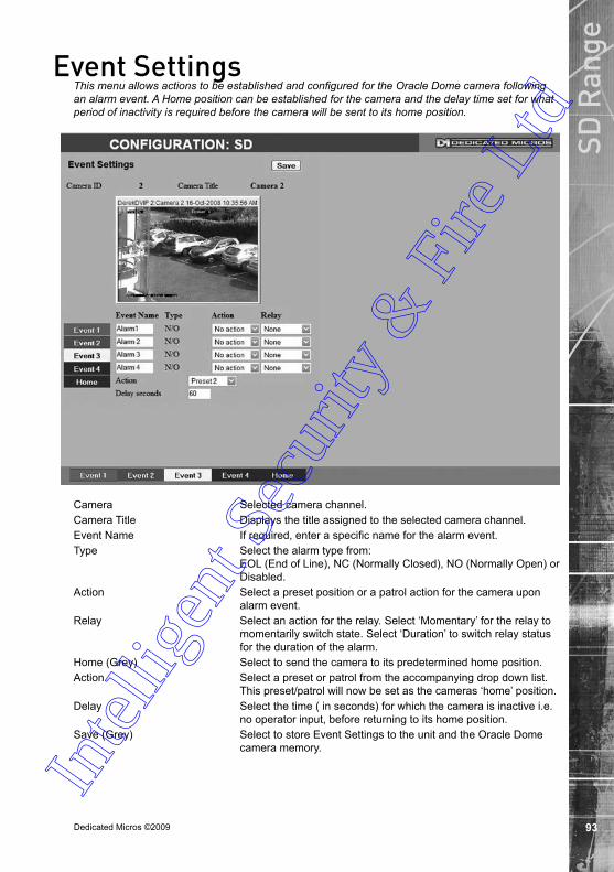
Dedicated Micros ©2009
SD R
ange
Event SettingsThis menu allows actions to be established and configured for the Oracle Dome camera following an alarm event. A Home position can be established for the camera and the delay time set for what period of inactivity is required before the camera will be sent to its home position.
Camera Selected camera channel.Camera Title Displays the title assigned to the selected camera channel.Event Name If required, enter a specific name for the alarm event.Type Select the alarm type from:
EOL (End of Line), NC (Normally Closed), NO (Normally Open) or Disabled.
Action Select a preset position or a patrol action for the camera upon alarm event.
Relay Select an action for the relay. Select ‘Momentary’ for the relay to momentarily switch state. Select ‘Duration’ to switch relay status for the duration of the alarm.
Home (Grey) Select to send the camera to its predetermined home position.Action Select a preset or patrol from the accompanying drop down list.
This preset/patrol will now be set as the cameras ‘home’ position.Delay Select the time ( in seconds) for which the camera is inactive i.e.
no operator input, before returning to its home position.Save (Grey) Select to store Event Settings to the unit and the Oracle Dome
camera memory.
Intel
ligen
t Sec
urity
& F
ire L
td
Dedicated Micros ©2009
SD R
ange
Unit OperationThe unit can be operated via the Viewer menus and the enclosed IR Remote Control, the optional keyboard or with a USB mouse. They can also be viewed and accessed remotely via the webpages and the ‘Viewer’ menu option.
Operating the ViewerNavigation is via a colour coded softkey system. The coloured menu provides an intuitive approach to operator and installer use. The coloured keys on the IR Remote Control correspond to the menu options displayed on screen.
Note: The screen images shown throughout this section are those displayed on a local monitor. If viewing remotely via the webpages, the menu layout will differ slightly.
The function of the keys will change according to whether the unit is in Live or Playback mode.
Overleaf are described the available Viewer menu pages. To display the colour coded menu options, press the OK button on the IR Remote Control or click the mouse button.
Intel
ligen
t Sec
urity
& F
ire L
td

Dedicated Micros ©2009
SD R
angeView Control
Red Full Show currently selected camera full screen.Green Quad Displays four images on-screen, putting
the currently selected camera in the top left segment of the four, and will increment all cameras by one if pressed again i.e. if cam 1 is shown top left, cam 2 top right etc. then the views will increment to cam 2 top left, cam 3 top right etc.
Note: When a camera button is pressed to select a new camera, the new selection will be displayed in the top left hand corner of the display. The next three connected cameras will be displayed in the following three positions.
Yellow Multi By default displays nine images on-screen, putting the currently selected camera in the top left segment, followed by the next eight cameras and will increment all cameras by one if pressed again i.e. if cam 1 is shown top left, cam 2 adjacent etc. then the views will increment to cam 2 top left, cam 3 adjacent etc.
Note: The Multi option not available on 4-way model.Note: For optimal performance, it is recommended that the multiscreen view be matched to the
number of connected cameras. The default multiscreen display settings can be configured in the Configuration menus via Console Settings->Viewer Defaults->Default Multi Display.
Blue Seq Select to display images from all connected cameras in a sequential order.
Note: The Seq option not available on 4-way model.Purple Next Opens the next page of the Viewer menu. In
tellig
ent S
ecur
ity &
Fire
Ltd
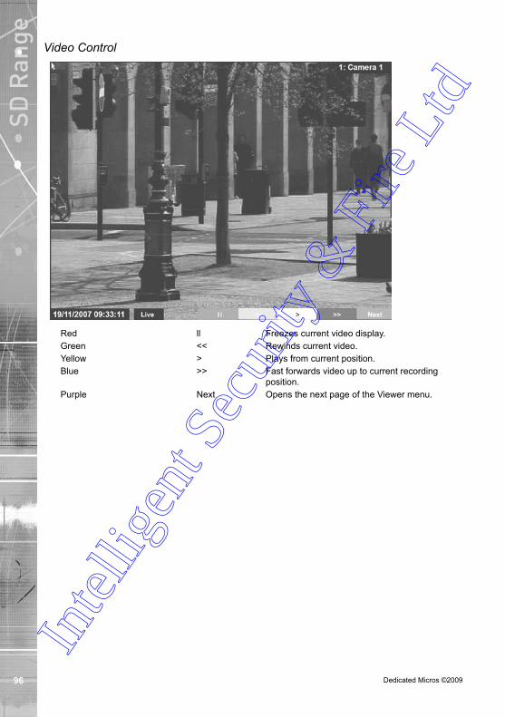
Dedicated Micros ©2009
SD R
ange Video Control
Red ll Freezes current video display.Green << Rewinds current video.Yellow > Plays from current position.Blue >> Fast forwards video up to current recording
position.Purple Next Opens the next page of the Viewer menu.
Intel
ligen
t Sec
urity
& F
ire L
td

Dedicated Micros ©2009
SD R
angeSelection Page
The Selection page allows access to various image and event playback functions.
Red Play Switches the selected camera(s) shown onscreen into Play mode.
Green Goto Opens the GoTo menu.Yellow Event Displays the Events menu.Blue Menu/Setup* Opens the Configuration menu pages.IMPORTANT: Selecting this option will exit the Viewer menus. This will be logged in the User
Activity Log as the current user terminating the session, refer to ‘Appendix C’ for further information regarding the User Activity Log.
Purple Next Opens the next page of the Viewer menu.Note: Menu will be displayed in the local viewer, Setup will be displayed in the remote viewer.
Intel
ligen
t Sec
urity
& F
ire L
td

Dedicated Micros ©2009
SD R
ange PTZ Program Option
The Program page allows preset settings for PTZ cameras to be established and an ‘Origin’ base position established for a camera.
Note: This page will not be available for all cameras.
Red Preset If Preset positions have been established for the PTZ camera, select the Preset option and enter a preset number. Refer to the ‘Presets’ menu page for further details on establishing preset positions.
Yellow Patrol If Patrols have been established for the camera, select the Patrol option and enter a number. Refer to the ‘Patrols’ menu page for further details on establishing Patrols.
Blue Prog Opens the ‘Dome Menu Option’ page.Purple Next Opens the next page of the Viewer menu.
Intel
ligen
t Sec
urity
& F
ire L
td

Dedicated Micros ©2009
SD R
angeProgram Page
The Program Menu page allows the PTZ configuration on the currently selected Telemetry camera to be accessed and configured (if such menus are available).
Red Dome Select to display the Dome Menu page. Green Store Use to save the current view as a Preset for this
camera. Press this button then a preset position (using the numeric keys on the IR Remote Control or optional Keyboard if viewing via a local monitor). To re-send the camera to this position, select the camera, then press Next -> Preset -> (preset number).
Note: When entering a new preset, any previous preset assigned to that number (for the same camera) will be overwritten.
Yellow Select This option will send the camera to the stored ‘Preset1’ position.
Blue Set Origin The Origin option allows a base position to be established for the Oracle dome camera. The camera will register this position as zero degrees. Any command that sends the camera to a coordinate will use this origin as its starting point..
Note: This option is only available for Oracle dome cameras. Purple Back Return to the ‘PTZ Program Option’ page.
Intel
ligen
t Sec
urity
& F
ire L
td

Dedicated Micros ©2009100
SD R
ange GoTo Page
The GoTo Navigation page allows quick and easy investigation of recorded video data. Use the Time and Date options to view recorded images from the camera channel currently being viewed.
Time Enter the required time (using the 24hr clock)Date Enter the required dateEarliest Recording The earliest recording time available for the camera currently
being viewed will be displayed.
Intel
ligen
t Sec
urity
& F
ire L
td
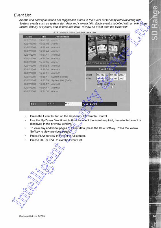
Dedicated Micros ©2009 101
SD R
angeEvent List
Alarms and activity detection are tagged and stored in the Event list for easy retrieval along with System events such as system start data and camera fails. Each event is labelled with an event type (alarm, activity or system) and its time and date. To view an event from the Event list:
• Press the Event button on the Keyboard/ IR Remote Control.• Use the Up/Down Directional buttons to select the event required, the selected event is
displayed in the preview window.• To view any additional pages of Event data, press the Blue Softkey. Press the Yellow
Softkey to view previous pages.• Press PLAY to view the event in full screen.• Press EXIT or LIVE to exit the Event List.
Intel
ligen
t Sec
urity
& F
ire L
td

Dedicated Micros ©200910
SD R
ange Event Search Filter
It is possible to filter the event search by time. Use the Directional buttons on the Keyboard/IR Remote Control to move to the Event Filter textbox. Enter the required Start and End time for the search and select the Blue search option. If required, also select via the checkbox options which specific events are to be searched. It is also possible to filter the search by type (alarm, activity or system) by pressing the corresponding coloured Softkey:
Alarm - Red
Activity - Green
System - Yellow
Play an event back full screenHighlight the relevant event and press PLAY. Tap the EVENT button on the IR Remote Control to return to the Event list.
Copy Events To The Archive ListTo copy events to the Archive list, select the event and Press the COPY button. The duration of the event will be copied to the Archive list. To archive to CD/USB, refer to the Copy Menu section on the following page.
START A NEW SEARCH
If you wish to start a new search filter, tap the EVENT button to exit the Event list, then re-enter data in the Event Search Filter menu
Intel
ligen
t Sec
urity
& F
ire L
td
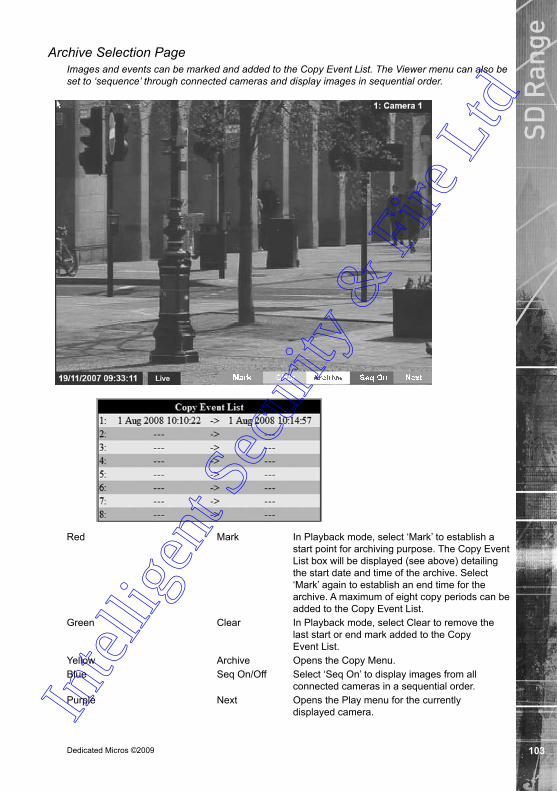
Dedicated Micros ©2009 10
SD R
angeArchive Selection Page
Images and events can be marked and added to the Copy Event List. The Viewer menu can also be set to ‘sequence’ through connected cameras and display images in sequential order.
Red Mark In Playback mode, select ‘Mark’ to establish a start point for archiving purpose. The Copy Event List box will be displayed (see above) detailing the start date and time of the archive. Select ‘Mark’ again to establish an end time for the archive. A maximum of eight copy periods can be added to the Copy Event List.
Green Clear In Playback mode, select Clear to remove the last start or end mark added to the Copy Event List.
Yellow Archive Opens the Copy Menu.Blue Seq On/Off Select ‘Seq On’ to display images from all
connected cameras in a sequential order.Purple Next Opens the Play menu for the currently
displayed camera.Intel
ligen
t Sec
urity
& F
ire L
td
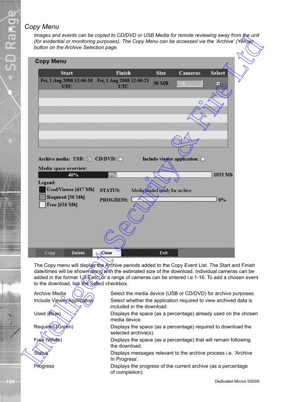
Dedicated Micros ©200910
SD R
ange Copy Menu
Images and events can be copied to CD/DVD or USB Media for remote reviewing away from the unit (for evidential or monitoring purposes). The Copy Menu can be accessed via the ‘Archive’ (Yellow) button on the Archive Selection page.
The Copy menu will display the Archive periods added to the Copy Event List. The Start and Finish date/times will be shown along with the estimated size of the download. Individual cameras can be added in the format 1,3,5 etc; or a range of cameras can be entered i.e.1-16. To add a chosen event to the download, tick the Select checkbox.
Archive Media Select the media device (USB or CD/DVD) for archive purposes.Include Viewer Application Select whether the application required to view archived data is
included in the download. Used (Blue) Displays the space (as a percentage) already used on the chosen
media device.Required (Green) Displays the space (as a percentage) required to download the
selected archive(s).Free (White) Displays the space (as a percentage) that will remain following
the download.Status Displays messages relevant to the archive process i.e. ‘Archive
In Progress’.Progress Displays the progress of the current archive (as a percentage
of completion).
Intel
ligen
t Sec
urity
& F
ire L
td

Dedicated Micros ©2009 10
SD R
ange1. Insert a USB Device into the USB port on the front of the unit.
2. Select USB from the Archive Media checkbox.3. Select the Copy option (Red) to start archive.4. Selected items are then saved to the USB device. 5. The USB export progress is displayed as a %. On completion the status will read
‘Archive Complete’.
To Copy Events/Images to a CD/DVD1. Insert a CD/DVD Device into the CD/DVD drive on the front of the unit.2. Select CD/DVD from the Archive Media checkbox.3. Select the Copy option (Red) to start archive.4. Selected items are then saved to the CD/DVD. 5. The CD/DVD export status is displayed as a %. On completion the status will read
‘Archive Complete’.
Intel
ligen
t Sec
urity
& F
ire L
td

Dedicated Micros ©200910
SD R
ange Using the IR Remote Control
By default, the I.R. Remote Control will be in “DVR” mode. If the unit does not respond to commands from the Remote Control, pressing the “DVR” button will always return the Remote Control to “DVR” mode. Pressing the “TV” button will switch to “TV” mode and send codes understood by common television sets (when preprogrammed to do so: see Appendix B).
Pressing any of the coloured Softkeys at any time will display the ‘coloured’ keys first and then access the equivalent ‘coloured’ option displayed in the menus.
For a description of the button commands available on the IR Remote Control, refer to the ‘IR Remote Control’ section.
Using the optional Keyboards (DM/KBC1 & DM/KBC)The unit can also be controlled using an optional Dedicated Micros keyboard. This is connected via the KBD connector on the rear of the unit and provides the same control functions as the I.R Remote Control. The following keyboards are supported:
DM/KBC1 Keyboard
Intel
ligen
t Sec
urity
& F
ire L
td

Dedicated Micros ©2009 10
SD R
angeDM/KBC2 Keyboard
Note: Not all buttons detailed below are relevant for both models of keyboard.
Key Function
Displays the Softkeys menu if not currently on screen. Selects the colour coded item displayed on screen.
Switches from Playback to Live mode.
Toggles the visibility of on-screen text and status bar if no Softkeys are on screen. (For future use).
For future use.
Displays the Softkey options for the Audio functions (for future use).
Forces all the cameras to record in alarm mode for three minutes, or until the button is pressed again (for future use).
Play mode - Marks start and end of archiving point. Live mode - Opens the Archive Copy menu.
Live mode - No functionality.
Play mode - Starts fast forwarding from play time.
Rewind mode - Starts fast forwarding from play time.
Pause mode - Steps forward one frame.In
tellig
ent S
ecur
ity &
Fire
Ltd
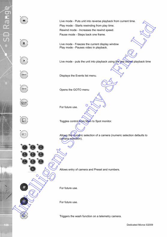
Dedicated Micros ©200910
SD R
ange
Live mode - Puts unit into reverse playback from current time.
Play mode - Starts rewinding from play time.
Rewind mode - Increases the rewind speed.
Pause mode - Steps back one frame.
Live mode - Freezes the current display window Play mode - Pauses video in playback.
Live mode - puts the unit into playback using the last stored playback time
Displays the Events list menu.
Opens the GOTO menu
For future use.
Toggles control from Main to Spot monitor.
Allows the numeric selection of a camera (numeric selection defaults to camera selection).
Allows entry of camera and Preset and numbers.
For future use.
For future use.
Triggers the wash function on a telemetry camera.In
tellig
ent S
ecur
ity &
Fire
Ltd

Dedicated Micros ©2009 10
SD R
ange
Triggers the wipe function on a telemetry camera.
Switches on the lamp on a telemetry camera.
Adjusts the focus to objects nearer the camera.
Adjusts the focus to objects further from the camera.
Closes the Iris on a Telemetry camera.
Opens the Iris on a Telemetry camera.
Zooms in on a telemetry camera and also provides electronic zoom out.
Zooms out on a telemetry camera and also provides electronic zoom in.
Sends a Patrol command to a telemetry camera.
Instructs the selected telemetry camera to automatically pan (on cameras that support this function).
Used as menu and on-screen navigation keys. Pan and tilt control for telemetry cameras.
In Play mode: Used to Mark Start/End positions.
ln Live mode: Displays the Copy List and archive controls.
Exits menus.In
tellig
ent S
ecur
ity &
Fire
Ltd
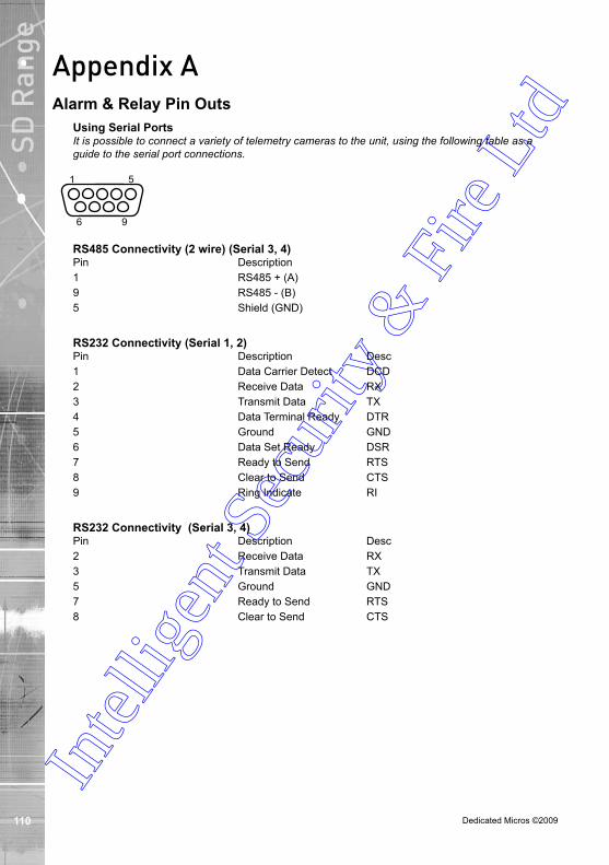
Dedicated Micros ©2009110
SD R
ange
Appendix AAlarm & Relay Pin Outs
Using Serial PortsIt is possible to connect a variety of telemetry cameras to the unit, using the following table as a guide to the serial port connections.
1 5
6 9
RS Connectivity ( wire) (Serial , )Pin Description1 RS485 + (A)9 RS485 - (B)5 Shield (GND)
RS Connectivity (Serial 1, )Pin Description Desc1 Data Carrier Detect DCD2 Receive Data RX3 Transmit Data TX4 Data Terminal Ready DTR5 Ground GND6 Data Set Ready DSR7 Ready to Send RTS8 Clear to Send CTS9 Ring Indicate RI
RS Connectivity (Serial , )Pin Description Desc2 Receive Data RX3 Transmit Data TX5 Ground GND7 Ready to Send RTS8 Clear to Send CTS
Intel
ligen
t Sec
urity
& F
ire L
td
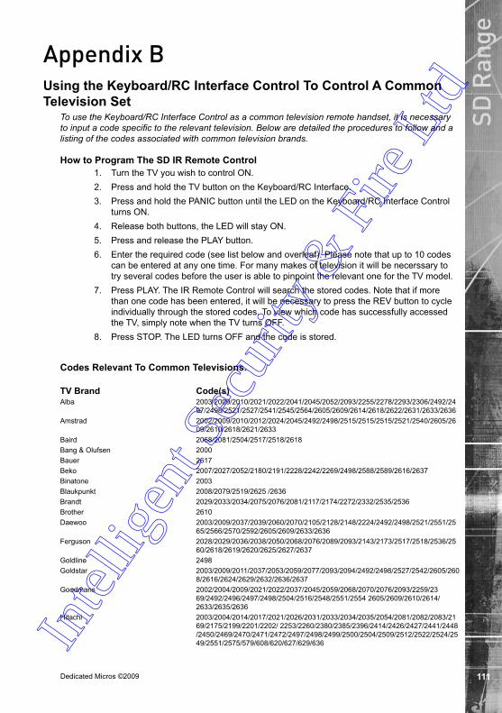
Dedicated Micros ©2009 111
SD R
ange
Appendix BUsing the Keyboard/RC Interface Control To Control A Common Television Set
To use the Keyboard/RC Interface Control as a common television remote handset, it is necessary to input a code specific to the relevant television. Below are detailed the procedures to follow and a listing of the codes associated with common television brands.
How to Program The SD IR Remote Control1. Turn the TV you wish to control ON.2. Press and hold the TV button on the Keyboard/RC Interface.3. Press and hold the PANIC button until the LED on the Keyboard/RC Interface Control
turns ON.4. Release both buttons, the LED will stay ON.5. Press and release the PLAY button. 6. Enter the required code (see list below and overleaf). Please note that up to 10 codes
can be entered at any one time. For many makes of television it will be necerssary to try several codes before the user is able to pinpoint the relevant one for the TV model.
7. Press PLAY. The IR Remote Control will search the stored codes. Note that if more than one code has been entered, it will be necessary to press the REV button to cycle individually through the stored codes. To view which code has successfully accessed the TV, simply note when the TV turns OFF.
8. Press STOP. The LED turns OFF and the code is stored.
Codes Relevant To Common Televisions.
TV Brand Code(s)Alba 2003/2009/2010/2021/2022/2041/2045/2052/2093/2255/2278/2293/2306/2492/24
97/2498/2521/2527/2541/2545/2564/2605/2609/2614/2618/2622/2631/2633/2636Amstrad 2002/2009/2010/2012/2024/2045/2492/2498/2515/2515/2515/2521/2540/2605/26
09/2610/2618/2621/2633Baird 2068/2081/2504/2517/2518/2618Bang & Olufsen 2000Bauer 2617Beko 2007/2027/2052/2180/2191/2228/2242/2269/2498/2588/2589/2616/2637Binatone 2003Blaukpunkt 2008/2079/2519/2625 /2636Brandt 2029/2033/2034/2075/2076/2081/2117/2174/2272/2332/2535/2536Brother 2610Daewoo 2003/2009/2037/2039/2060/2070/2105/2128/2148/2224/2492/2498/2521/2551/25
65/2566/2570/2592/2605/2609/2633/2636Ferguson 2028/2029/2036/2038/2050/2068/2076/2089/2093/2143/2173/2517/2518/2536/25
60/2618/2619/2620/2625/2627/2637Goldline 2498Goldstar 2003/2009/2011/2037/2053/2059/2077/2093/2094/2492/2498/2527/2542/2605/260
8/2616/2624/2629/2632/2636/2637Goodmans 2002/2004/2009/2021/2022/2037/2045/2059/2068/2070/2076/2093/2259/23
69/2492/2496/2497/2498/2504/2516/2548/2551/2554 2605/2609/2610/2614/ 2633/2635/2636
Hitachi 2003/2004/2014/2017/2021/2026/2031/2033/2034/2035/2054/2081/2082/2083/2169/2175/2199/2201/2202/ 2253/2260/2380/2385/2396/2414/2426/2427/2441/2448/2450/2469/2470/2471/2472/2497/2498/2499/2500/2504/2509/2512/2522/2524/2549/2551/2575/579/608/620/627/629/636In
tellig
ent S
ecur
ity &
Fire
Ltd

Dedicated Micros ©200911
SD R
ange JVC 2021/2037/2045/2050/2210/2216/2239/2240/2267/2276/2280/2282/2298/2333/23
77/2397/2497/2502/2507/ 2517/2518/2521/ 2557/2563/ 2572/2577/2597/2609/2615/2616/2622/2636/2646
LG 2003/2009/2011/2037/2053 /2055/2059/2077/2084/2093/2094/2195/2200/2237/2245/2261/2262/2263/2274/2287/2312/2330/2355/2356/2359/2364/2381/2389 /2451/2452/2492/2498/2527/2542/2580/2581/2582/2594/2596/2598/2600/2605/ 2608/2616/2645/2647/649
Panasonic 2042/2043/2044/2063/2074/2085/2086/2100/2107/2114/2123/2130/2134/2136/2138/2168/2187/2226/2252/2324/2357/2361/2388/2408/2415/2416/2428/2429/2473/2474/2475/2498/2511/2520/2523/2528/2562/2578/2585/2599/2601/2603/2620/2636/640/
648Philips 2000/2003/2031/2032/2037/2055/2056/2068/2070/2087/2093/2108/2109/211
2/2115/2119/2122/2126/2129/2131/2132/2133/2141/2146/2147/2149/2150 2152/2154/2155/2157/2163/2170/2182/2183/2190/2192/2197/2206/2214/2215/2229/2231/2246/2248 2249/251/254/257/264/275/277/283/291/297/323 /338/339/343 /383/384/393/398/436/453/454/476/477/478/479/480/481/495/498/499/554/567/568573/604/623/624 /627/629/ 635 /636/637/643/644
Pioneer 2029/2037/2081 /2093/2379/2382/2387/2390/2392/2444/2449/2498/2584/2627/26/2637
Sanyo 2003/2004/2006/2014/2016/2021/2023/2024/2025/2030/2032/2076/2088/2161/2220/2223/2290/2292/2401/2442/2443/2492/2494/2497/2501/2504/2513/2532/2605/2627/2629/2633
Sharp 2001/2005/2023/2040/2101/2102/2127/2139/2160/2162/2186/2193/2207/2219/2335/2352/2354/2360/2365/2366/2368/2372/2373/2376/2403/2407/2417/2422/2423/2424/2430/2431/2432/2433/2434/2455/2456/2457/2458/2459/2460/2461/2462/2463/2483/497/502/506/513/533
Sony 2004/2009/2021/2023/2024/2047/2067/2076/2078/2091/2097/2098/2110/2111/2118/2121/2125/2135 /2142/2166/2177/2185/2204/2234/2236/2326/2344 /2345/2346/2349/2363/ 2400/2402/2404/2405/2410 /2413/2418/2420/2439//2493/2494/2497/2508 /2569/2571/587/602/603/607/639
Technics 2043Toshiba 2015/2021/2051 /2069/2090/2103/2137/2158/2159/2165/2179/2188/2194
/2208/2211/2213/2217 /2218/2222/2243/2244/2250/2271/2284/2288/2294 /2303 /2304/2313/2318/2319/2320/2321/2322/2328/2347/2350/2370/2375/2394/2409/2421/2435/2437/2440/2465/466/467/485/487/489/490/496/497/503/508 /526/574/54/591/595/606/607/632/642
CO
Intel
ligen
t Sec
urity
& F
ire L
td

Dedicated Micros ©2009 11
SD R
ange
Appendix CUser Activity Logging
User Activity logging can be enabled or disabled via the System Setting->Features menu. When this feature is enabled, the unit will record all actions performed via the user interface. These actions include Viewing the live stream, activating telemetry, altering the unit configuration, viewing recorded video, archiving video and any system events such as restarting the unit.
Data recorded will include the user name, login time and date, what action was performed, which channels were viewed and which telemetry instructions were issued.
The log files will be retained on the unit for as long as any related video files are kept. One log file will be created daily as a text file and will be named automatically (using the date of creation), and stored in the logs directory on the unit. This can then be downloaded via ftp if required.
Action Stored DataUser Login Username, Local or Remote, Login
Local Archive Username, Local or Remote control, Media
Remote Raw Archive 1 http Username, Submission requesting archive time
Remote Selective Archive http Username, Submission requesting archive time
Remote Raw Archive 2 FTP Username, List of downloaded files
Telemetry IP address of user, Local or Remote, Channel Controlled,
Command sent
Configuration Username, Local or remote, Menus changed, Items changed
Playback Username, Remote, Channel viewed, From time
Live Username, Remote, Channel viewed
System Events Username, Event Info
Intel
ligen
t Sec
urity
& F
ire L
td

Dedicated Micros ©200911
SD R
ange
Appendix D For guidance on locating the unit’s IP address via a serial port connection, please see below:
Locating the unit IP address using the serial port
1. With the mains power off, connect a standard 9DF-9DF RS232 communications cable from the PC to one of the serial port connections on the rear of the unit.
2. On the PC, click Start->Programs->Accessories->Communications->Hyperterminal and create a new connection via the COM port using these settings.
Bits per second 115200 Data Bits 8 Parity None Stop bits 1 Flow Control None
3. Power the unit, the Power LED on the unit will illuminate.
4. Hyperterminal will display the communications information as the unit boots up. This will include the IP address, Subnet and Gateway.
Intel
ligen
t Sec
urity
& F
ire L
td

Dedicated Micros ©2009 11
SD R
ange
Appendix EUnit Specification
LANGUAGES Including: English, French, Italian, German, Spanish, Portuguese, Dutch, Danish, Finnish, Norwegian, Swedish and Russian.
SUPPORTED USB DEVICESCrucial High Speed USB SD/MMC Card Reader (CTR2MMPU2) with SanDisk Standard SD Card 2GB (SDSDB-2048)Crucial High Speed USB Compact Flash Card Reader (CTR2ADPU2) with SanDisk Standard CompactFlash Card 4GB (SDCFB-4096).Crucial 40x Speed USB Flash Drive 512MB (CT512MBUFD).SanDisk Cruzer Micro USB Flash Drive 4GB.Buffalo RUF-C/U2 128MB/256MB USB stick.
CAMERAS4, 8, 12, 16 and 32 camera inputs available. Auto detection on power up. Looping BNC connectors provided for each camera input (except 32 way unit). Alarm on Camera Fail.Option to view all or selected cameras without effecting recording.
MONITOR VIEWINGMain monitor:Full screen, picture in picture, quad viewing and multiscreen.Mon A: Composite video BNC connector.Spot monitor: Full screen, sequence.Mon B: Composite video BNC connector.
ACTIVITY DETECTIONEach activity detection will switch the selected camera from normal record profile to alarm record profile. This feature can also; log the event, activate a relay, trigger a sounder, switch camera or link to an alarm.Individual configurable alarm responses include; move camera to preset, activate a relay, remote alarm reporting, email on alarm, log event, switch camera, activate sounder.
ALARMS & RELAYS16 normally open/closed tamper proof alarm inputs via back panel.Keyswitch alarm.4 relay outputs.
AUDIOThe user has the option to record and play back audio through the unit in real time. Recorded with images, audio can be played back directly from the unit via powered external speakers.Audio output for on site PA/Challenge.Connections:Line in: 1V pk-pk, RCA phono socket.Line out: 1V pk-pk, RCA phono socket.
SEARCH AND PLAYBACK• Frame advance/rewind, fast picture search and pause keys.• Event list, including event list filter with unique quadrant preview facility.• GOTO time and date.• Playback in quad, multiscreen, picture in picture and full screen.
MultiMode RECORDINGMultiMode recording gives you the ability to set different record rates, resolutions and compression algorithms (MPEG-4/JPEG) across scheduled, normal and alarm modes dynamically on individual cameras.
RECORDINGPlayback and record to hard disk simultaneously.Alarmed or manually selected images can be protected from being overwritten.Timed expiry option allows images to be held for a selected number of days.
Intel
ligen
t Sec
urity
& F
ire L
td

Dedicated Micros ©200911
SD R
ange EVENT COPYING
Event sequences and user defined recorded sequences can be saved to a CD via the integrated CD-writer or to an external flash drive through the USB port.
TEXT SUPPORTThrough the inclusion of Text Support, the SD can search capturedtransaction data for specific goods purchased, transaction numbers,credit card references, keywords etc. and jump straight to the associatedvideo sequence.Text Support can be assigned to any 2 cameras on the unit.
NETWORKING CAPABILITIESA standard Ethernet connection allows live and recorded viewing ona networked PC using DM’s NetVu ObserVer software. Networkviewing is independent and does not affect the recording or localoperation. The SD Range includes a network bandwidth limitation option,which allows the bandwidth used by the SD Range to be capped.For low bandwidth remote network links, viewing applications canrequest that video is sent in MPEG-4 format, while local networkviewers can simultaneously view using high quality JPEG images.
KEYBOARD/RC INTERFACE CONTROLOffering full system control.
OPTIONAL KEYBOARDSSupports Dedicated Micros keyboards: DMKBC1 DMKBC2
TELEMETRYBuilt-in RS485/Twisted pair protocols provide direct control of the numerous domes including but not limited to the following:• Dedicated Micros Serial • AD Matrix/AD 168-Matrix• Baxall C• BBV C/RS485/Matrix• Dennard/Dennard C• Ernitec• JVC • Kalatel• MarkMercer• Panasonic WV-CS600/WV-CS850• Pelco C• Philips/Philips 232• Samsung• Sanyo• Sensormatic• Ultrak• Vantage• VCL/VCL-Matrix• Vicon• Vista
COLOUR RESOLUTIONSampling rate: 13.5 MHz to CCIR 60116.8 million colours 256 levels of grey, 8-bit luma
COMPRESSIONJPEG & MPEG-4 format files. JPEG: 4CIF, 2CIF, CIF & QCIF resolution.MPEG-4: 2CIF, CIF & QCIF.User definable file size and bit rate.
SD RANGE DATASerial Ports: 4 - 2 xRS232 (9 wire) or (3 wire), 2 x RS232 (3 wire), RS485.Ethernet: 1x Ethernet RJ-45 10/100 Ethernet connection.USB: 3 x USB 2.0 Connector (1 positioned on the front panel).
TEMPERATURE RANGE5 - 40°C
RELATIVE HUMIDITY10% - 85% Non-condensing.
UNIT DIMENSIONS435mm deep, 440mm wide, 98mm high.
Intel
ligen
t Sec
urity
& F
ire L
td

Dedicated Micros ©2009 11
SD R
ange
Intel
ligen
t Sec
urity
& F
ire L
td

Dedicated Micros ©200911
SD R
ange
IndexAccessing the Configuration Webpages ...................... 20Accessing the menus on a local monitor ..................... 19Accessing the menus on a PC web browser ............... 19Activity Response Setup .............................................. 67Activity Setup ............................................................... 65Advanced Record ....................................................... 54Alarm & Relay Pin Outs ............................................. 110Alarm Input ....................................................................... 59Alarms and relays ........................................................ 12Alarm Status ................................................................ 32Archive ......................................................................... 83Archive Selection Page .............................................. 103Audio ............................................................................ 11Audio ............................................................................ 36Before you start .............................................................. 8Camera ........................................................................ 47Camera Settings .......................................................... 91Camera Setup ............................................................. 48Camera Telemetry ........................................................ 49CE Mark ......................................................................... 7Check the contents of the box ....................................... 8Choosing a location for installation ................................ 8Co .............................................................................. 112Codes Relevant To Common Televisions. ...................111COMMON CONFIGURATION INTERFACE .................. 4Complete Flexibility ........................................................ 9Configuration ................................................................ 39Copy Events To The Archive List ............................... 101Copy Menu ................................................................. 104Data ............................................................................. 10Data ............................................................................. 11Default DNS Address ................................................... 19Design of the manual ..................................................... 5Display ........................................................................ 43DM/KBC1 Keyboard ................................................... 106DM/KBC2 Keyboard ................................................... 107Electrical Connections ................................................... 8E Mail ........................................................................... 75End Of Line Circuitry .................................................... 16Entering Alpha-Numeric Data via a Local Monitor ....... 25Event List ................................................................... 101Event Search Filter .................................................... 102Event Settings .............................................................. 93Features ...................................................................... 37For information on locating the unit’s IP address. ........ 19Front Panel connections .............................................. 10Global Actions .............................................................. 69GoTo Page ................................................................. 100Holiday & Weekend...................................................... 57How to Program The SD IR Remote Control ..............111Installing the SD Unit ................................................... 13Keyword ....................................................................... 82Language ..................................................................... 33Laser .............................................................................. 7Lightning Strike .............................................................. 6Live Transmissions ...................................................... 74Locating the Unit IP address ........................................ 19Locating the unit IP address using the serial port ...... 114Low ................................................................................ 9Maintain ....................................................................... 39Medium .......................................................................... 9MultiMode Recording ..................................................... 9
Network ........................................................................ 72Normal ........................................................................... 9Operating the Viewer ................................................... 94OSD Settings ............................................................... 90Patrols .......................................................................... 88Play an event back full screen ................................... 102Power ........................................................................... 12Power Sources ............................................................... 6Presets ......................................................................... 86Privacy Masks .............................................................. 89Profile Record .................................................................. 52Program Page .............................................................. 99PTZ Program Option .................................................... 98Quick Overview Of Default SD Record Settings ............ 9Read Instructions ........................................................... 6Rear Panel connections ............................................... 10Record ......................................................................... 51Regulatory Notes and FCC and DOC Information ......... 6Remote Reporting ........................................................ 77RS232 .......................................................................... 17RS232 Connectivity (Serial 1, 2) ................................ 110RS232 Connectivity (Serial 3, 4) ............................... 110RS485 .......................................................................... 17RS485 Connectivity (2 wire) (Serial 3, 4) ....................111Schedule ...................................................................... 56Sectors ........................................................................ 87Selection Page ............................................................ 97Serial Ports ................................................................. 35Servicing ........................................................................ 6Simple Record .................................................................. 52Status ........................................................................... 85Step 1 Connecting Video ............................................. 13Step 2 Monitor .............................................................. 13Step 3 Connecting Audio ............................................. 14Step 4 Connecting to the Network ............................... 14Step 5 Relays ............................................................... 15Step 6 Alarms ............................................................... 15Step 7 Connecting Serial Ports .................................... 17Step 8 Connecting a Keyboard .................................... 17Step 9 Connecting DM Oracle, 2060 & 2040 Domes .. 18Step 10 Connecting Power .......................................... 18System ......................................................................... 28Text In Image .............................................................. 80Time and Date ............................................................. 34To Copy Events/Images to a CD/DVD ....................... 105Unit Specification ....................................................... 115Unit Status .................................................................. 30User Accounts ............................................................. 44User Activity Logging ................................................. 113Using a USB Mouse or the Webpages ........................ 26Using Serial Ports ...................................................... 110Using the IR Remote Control ...................................... 25Using the IR Remote Control ..................................... 106Using the IR Remote Control to control a TV ..............111Using the optional Keyboards (DM/KBC1 & DM/KBC2) ... 106Ventilation ...................................................................... 6Video Control ............................................................... 96View Control ................................................................. 95Viewer Defaults ........................................................... 41Zone Actions ................................................................ 63Zone Input ........................................................................ 61In
tellig
ent S
ecur
ity &
Fire
Ltd

Dedicated Micros ©2009 11
SD R
ange
Intel
ligen
t Sec
urity
& F
ire L
td

MI-I-SD/E2-0
Dedicated Micros Ltd.1200 Daresbury Park, Daresbury,
Cheshire, WA4 4HS, UK
Installed by
Dedicated Micros France9-13 rue du Moulinet75013 Paris, France
Dedicated Micros, Australia PTY.5/3 Packard Avenue, Castle Hill,
NSW 2154, Australia
Dedicated Micros SloveniaDelavska cesta 26,
4208 Sencure, Slovenia
Dedicated Micros BeneluxJoseph Chantraineplantsoen 1,
3070 Kortenberg, Belgium
Dedicated Micros GermanyHamtorstaße 9
41460 Neuss, Germany
Dedicated Micros, Asia PTY16 New Industrial Road,
#03-03 Hudson Techno Centre,Singapore 536204
Dedicated Micros Middle EastBuilding 12, Suite 302,
P.O. Box 500291, Dubai Internet City, Dubai, United Arab Emirates
Dedicated Micros (Malta) Ltd.BLB017, Bulebel Industrial Estate,
Zejtun, ZTN3000, Malta
Dedicated Micros USA.14434 Albemarle Point Place, Suite 100,
Chantilly, Virginia 20151 USA
Intel
ligen
t Sec
urity
& F
ire L
td
![Micros Folder 10-2010 - nsc-ksa.comnsc-ksa.com/catalogue/NSC CATALOGUES/Microscopes/Micros/MC300serie.pdfhijgYn XdchigjXi^dc VcY ZVhn ]VcYa^c\ ^i ... micros micros micros micros micros](https://img.pdfslide.net/doc/110x75/5b1c97d97f8b9a2d258ff7ed/micros-folder-10-2010-nsc-ksacomnsc-ksacomcataloguensc-cataloguesmicroscopesmicros.jpg)