Embed Size (px)
Citation preview
Deep Borehole Disposal Research: Geological Data Evaluation, Alternative Waste Forms, and Borehole Seals
Prepared for U.S. Department of Energy
Used Fuel Disposition Campaign Bill W. Arnold, Patrick Brady,
Mark Sutton, Karl Travis Robert MacKinnon, Fergus Gibb, and
Harris Greenberg Sandia National Laboratories
September 5, 2014 FCRD-USED-2014-000332
SAND2014-17430 R
Sandia National Laboratories is a multi-program laboratory managed and operated by Sandia Corporation, a wholly owned subsidiary of Lockheed Martin Corporation, for the U.S. Department of Energy’s National Nuclear Security Administration under contract DE-AC04-94AL85000.
DISCLAIMER This information was prepared as an account of work sponsored by an agency of the U.S. Government. Neither the U.S. Government nor any agency thereof, nor any of their employees, makes any warranty, expressed or implied, or assumes any legal liability or responsibility for the accuracy, completeness, or usefulness, of any information, apparatus, product, or process disclosed, or represents that its use would not infringe privately owned rights. References herein to any specific commercial product, process, or service by trade name, trade mark, manufacturer, or otherwise, does not necessarily constitute or imply its endorsement, recommendation, or favoring by the U.S. Government or any agency thereof. The views and opinions of authors expressed herein do not necessarily state or reflect those of the U.S. Government or any agency thereof.
Deep Borehole Disposal Research September 5, 2014 iii
Revision 2 12/20/2012
APPENDIX E FCT DOCUMENT COVER SHEET1
NOTE 1: Appendix E should be filled out and submitted with the deliverable. Or, if the PICS:NE system permits, completely enter all applicable information in the PICS:NE Deliverable Form. The requirement is to ensure that all applicable information is entered either in the PICS:NE system or by using the FCT Document Cover Sheet NOTE 2: In some cases there may be a milestone where an item is being fabricated, maintenance is being performed on a facility, or a document is being issued through a formal document control process where it specifically calls out a formal review of the document. In these cases, documentation (e.g., inspection report, maintenance request, work planning package documentation or the documented review of the issued document through the document control process) of the completion of the activity, along with the Document Cover Sheet, is sufficient to demonstrate achieving the milestone. If QRL 1, 2, or 3 is not assigned, then the Lab / Participant QA Program (no additional FCT QA requirements) box must be checked, and the work is understood to be performed and any deliverable developed in conformance with the respective National Laboratory / Participant, DOE or NNSA-approved QA Program.
Name/Title of Deliverable/Milestone/Revision No.
Deep Borehole Disposal Research: Geological Data Evaluation, Alternative Waste Forms, and Borehole Seals M3FT-14SN0817021
Work Package Title and Number DR Deep Borehole Disposal – SNL, FT-13SN081702
Work Package WBS Number 1.02.08.17
Responsible Work Package Manager Robert J. MacKinnon
(Name/Signature) Date Submitted September 5, 2014 Quality Rigor Level for Deliverable/Milestone2
QRL-3 QRL-2 QRL-1 Nuclear Data
N/A*
This deliverable was prepared in accordance with Sandia National Laboratories (Participant/National Laboratory Name) QA program which meets the requirements of DOE Order 414.1 NQA-1-2000 Other This Deliverable was subjected to:
Technical Review Peer Review Technical Review (TR) Peer Review (PR) Review Documentation Provided Review Documentation Provided
Signed TR Report or, Signed PR Report or, Signed TR Concurrence Sheet or, Signed PR Concurrence Sheet or, Signature of TR Reviewer(s) below Signature of PR Reviewer(s) below
Name and Signature of Reviewers
Geoff Freeze

Deep Borehole Disposal Research iv September 5, 2014
This page intentionally left blank.
Deep Borehole Disposal Research September 5, 2014 v
CONTENTS
CONTENTS .....................................................................................................................................v
1. INTRODUCTION ..................................................................................................................1 1.1 Background ...................................................................................................................1 1.2 Objectives and Scope ....................................................................................................2
2. EVALUATION OF SUB-REGIONAL GEOLOGICAL INFORMATION..........................3 2.1 Representative Locations for a Deep Borehole Field Test ...........................................3 2.2 Screening of DOE Sites for a Deep Borehole Field Test .............................................4 2.3 Field Test Site Evaluation in Northeastern South Dakota ............................................9 2.4 Field Test Site Evaluation in the Texas Panhandle ....................................................20 2.5 Field Test Site Evaluation at the Savannah River Site ...............................................27
3. DISPOSAL SYSTEM DESIGN FOR ALTERNATIVE WASTE FORMS .......................33 3.1 Review of Alternative Waste Forms ...........................................................................33 3.2 Disposal of DOE Cs-137 and Sr-90 Capsules ............................................................34
3.2.1 Cs-137 and Sr-90 Capsule Inventory ..............................................................35 3.2.2 Disposal Canisters and Disposal Concepts .....................................................38 3.2.3 Disposal Borehole Design ..............................................................................41 3.2.4 Near-Field Thermal Analysis .........................................................................47 3.2.5 Thermal-Hydrologic Analyses ........................................................................71
3.3 Disposal of DOE Calcine Waste .................................................................................74 3.4 Degradation of Waste Canister Materials, Waste Forms and Drill Casing
Materials .....................................................................................................................75 3.4.1 Degradation of Waste Canister Materials .......................................................75 3.4.2 Disposal Canister Materials ............................................................................82 3.4.3 Degradation of Drill Casing Materials ...........................................................83
4. BOREHOLE SEALS RESEARCH AND PLANNING ......................................................86 4.1 Review of Seals Alternatives ......................................................................................86 4.2 Chemical, Mineralogical, and Physical Stability of Borehole Seals ..........................86
5. JOINT BOREHOLE DISPOSAL AND ENHANCED GEOTHERMAL ENERGY RD&D NEEDS ....................................................................................................................89
6. SUMMARY AND CONCLUSIONS ...................................................................................91
7. REFERENCES .....................................................................................................................94
Appendix A. SCREENING OF DOE SITES FOR A DEEP BOREHOLE FIELD TEST PROJECT ............................................................................................................... A-1
Deep Borehole Disposal Research vi September 5, 2014
FIGURES
Figure 2-1. Geothermal heat flow map of U.S. (Source: SMU Geothermal Laboratory). ............. 5
Figure 2-2. Seismic hazard map of U.S. showing areas with a 2% probability of peak ground acceleration (PGA) of a particular value in 50 Years. ......................................... 6
Figure 2-3. Depth to crystalline basement in the U.S. .................................................................... 7
Figure 2-4. Terrane map of the Precambrian basement of South Dakota (from McCormick 2010). Detailed study area outlined by the red rectangle. ........................ 11
Figure 2- 5. Depth to Precambrian Basement in the detailed South Dakota study area with borehole locations and rock type at the Precambrian unconformity (data from McCormick 2010). ......................................................................................................... 12
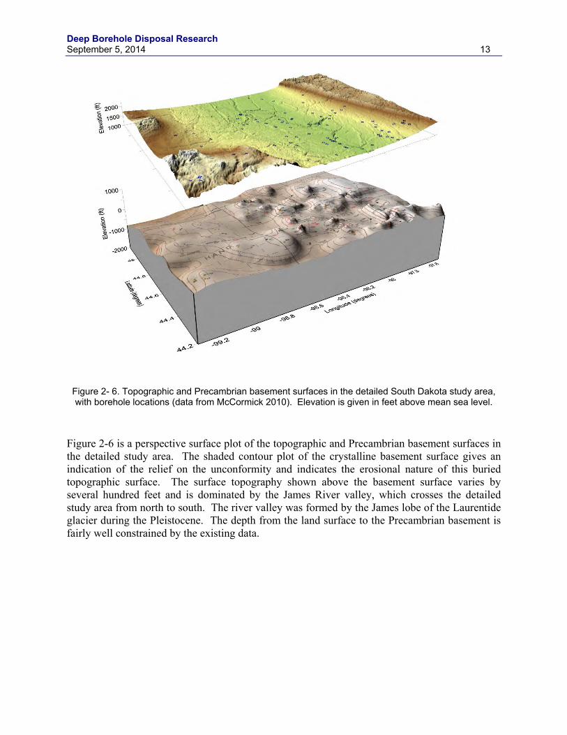
Figure 2- 6. Topographic and Precambrian basement surfaces in the detailed South Dakota study area, with borehole locations (data from McCormick 2010). Elevation is given in feet above mean sea level. ........................................................... 13
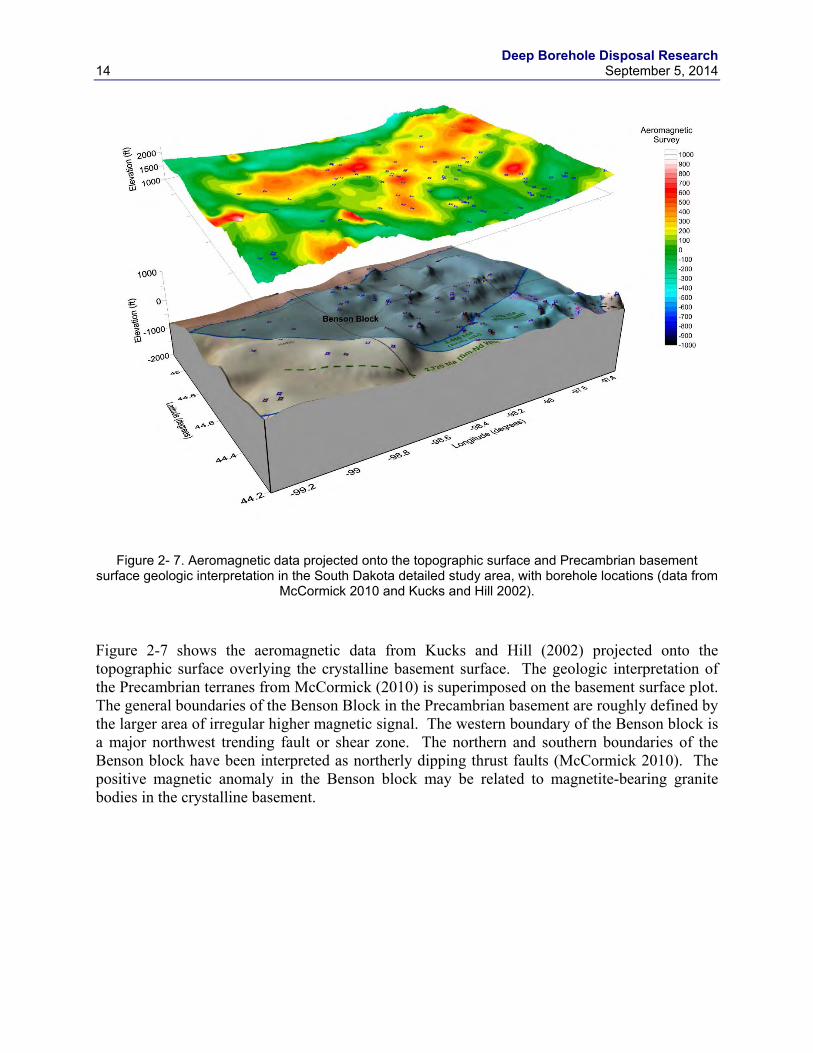
Figure 2- 7. Aeromagnetic data projected onto the topographic surface and Precambrian basement surface geologic interpretation in the South Dakota detailed study area, with borehole locations (data from McCormick 2010 and Kucks and Hill 2002). ............................................................................................................................. 14
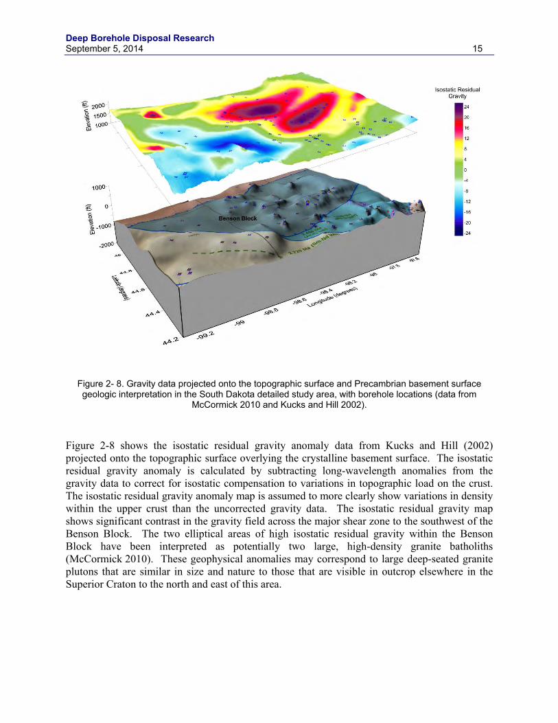
Figure 2- 8. Gravity data projected onto the topographic surface and Precambrian basement surface geologic interpretation in the South Dakota detailed study area, with borehole locations (data from McCormick 2010 and Kucks and Hill 2002). ............................................................................................................................. 15
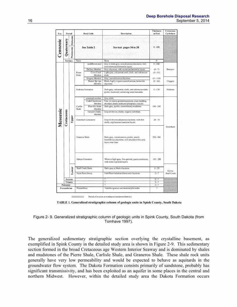
Figure 2- 9. Generalized stratigraphic column of geologic units in Spink County, South Dakota (from Tomhave 1997). ...................................................................................... 16
Figure 2- 10. Representative cross section of geologic units in Spink County, South Dakota (from Tomhave 1997). ...................................................................................... 17
Figure 2- 11. Earthquakes greater than magnitude 2 from 1980 to 2014 in South Dakota. (data from USGS Earthquake Hazards Program archive: http://earthquake.usgs.gov/earthquakes/search/ ) .......................................................... 18
Figure 2- 12 . Geothermal gradient in South Dakota (from Schoon and McGregor 1974). ......... 19
Figure 2- 13. Lithologic terrane map of the crystalline basement, Texas Panhandle. The Pantex Plant boundary is shown with the solid red line in western Carson County. (Dutton et al. 1982) ......................................................................................... 21
Figure 2- 14. Aeromagnetic data for the Texas Panhandle (Data from Bankey 2006). County boundaries and names are shown. The Pantex Plant boundary is shown with the solid red line in western Carson County. ......................................................... 22
Figure 2- 15. Isostatic gravity anomaly data for the Texas Panhandle (Data from Bankey 2006). County boundaries and names are shown. The Pantex Plant boundary is shown with the solid red line in western Carson County............................................... 23
Deep Borehole Disposal Research September 5, 2014 vii
Figure 2- 16. Structural contour map on the top of the crystalline basement, Texas Panhandle. (from Johnson 2013; original figure from Dutton et al. 1982) ................... 24
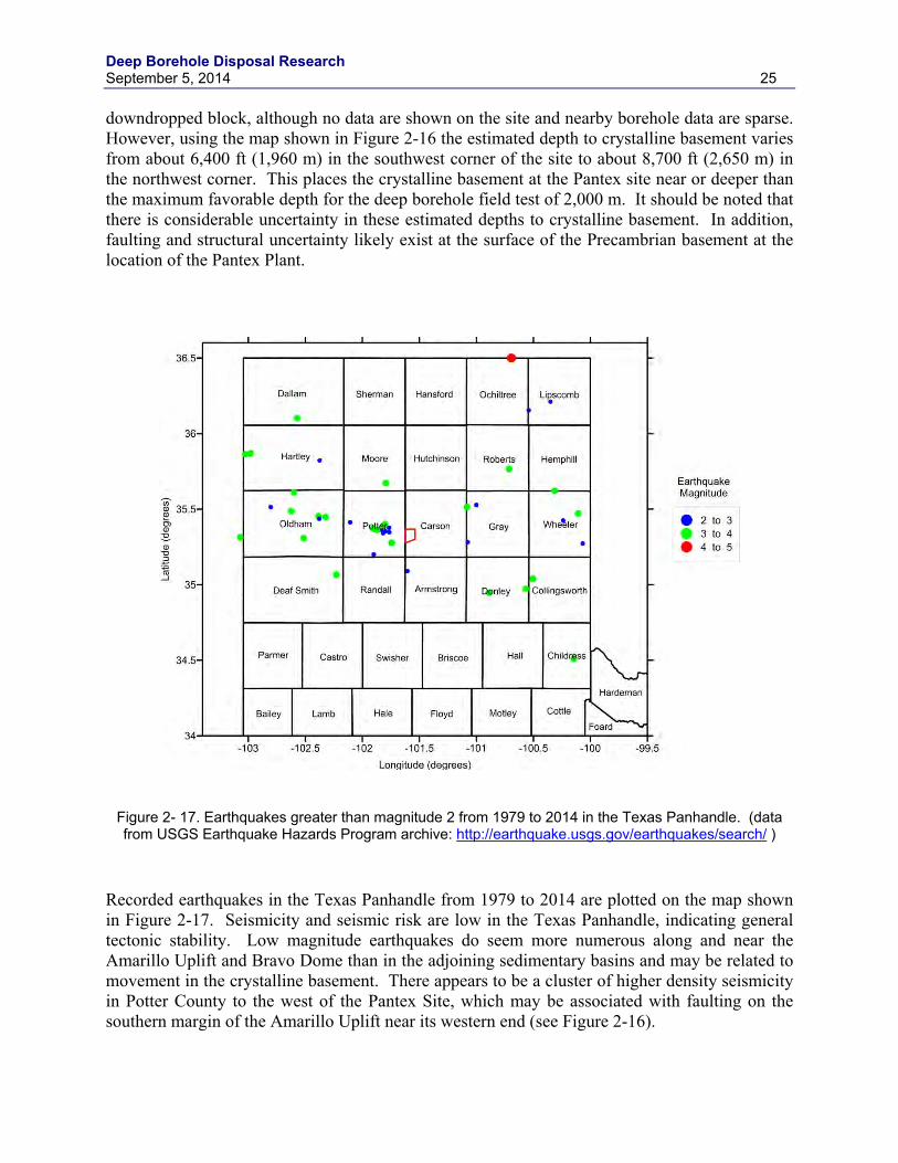
Figure 2- 17. Earthquakes greater than magnitude 2 from 1979 to 2014 in the Texas Panhandle. (data from USGS Earthquake Hazards Program archive: http://earthquake.usgs.gov/earthquakes/search/ ) .......................................................... 25
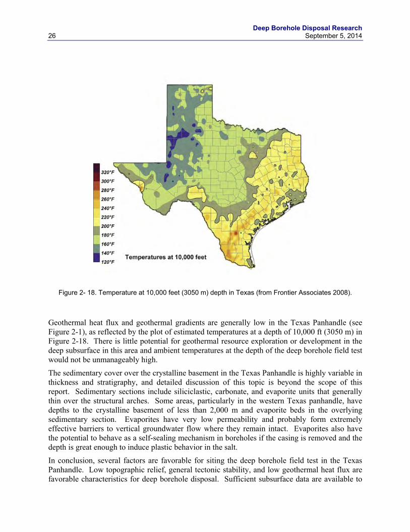
Figure 2- 18. Temperature at 10,000 feet (3050 m) depth in Texas (from Frontier Associates 2008). ........................................................................................................... 26
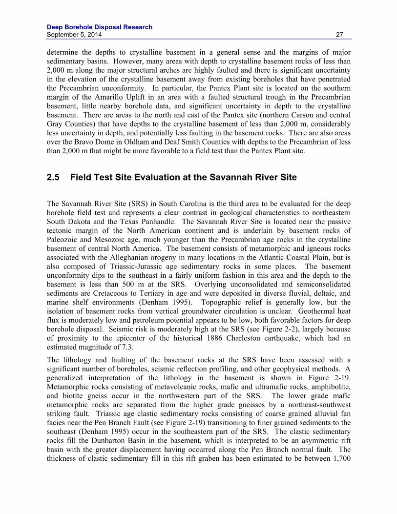
Figure 2- 19. Generalized geologic map of the pre-Cenozoic basement at the Savannah River Site area in South Carolina. (from Domoracki 1995) ......................................... 28
Figure 2- 20. Aeromagnetic data for the Savannah River Site area in South Carolina. County boundaries are shown. The SRS boundary is shown with the solid orange line. Boreholes to the crystalline basement shown with open circles. (Data from Daniels 2005) .............................................................................................. 29
Figure 2- 21. Isostatic gravity anomaly data for the Savannah River Site area in South Carolina. County boundaries are shown. The SRS boundary is shown with the solid orange line. Boreholes to the crystalline basement shown with open circles. (Data from Daniels 2005) .................................................................................. 30
Figure 2- 23. Earthquakes greater than magnitude 2 from 1974 to 2014 in the area of the Savannah River Site. The SRS boundary is shown with the solid orange line. (data from USGS Earthquake Hazards Program archive: http://earthquake.usgs.gov/earthquakes/search/ ) .......................................................... 32
Figure 3-1 . Typical Cs-137 capsule design (from Plys and Miller 2003). .................................. 35
Figure 3-2. Projected thermal output from Cs and Sr capsules. ................................................... 38
Figure 3-3. Horizontal cross section of “baseline” DBD concept for CsCl and SrF2 capsules. The dark blue ring is the drill casing. ............................................................. 39
Figure 3-4. Canister geometries for possible alternative DBD concepts for CsCl or SrF2 capsules. Colors represent components/materials as in Figure 3-3. ............................. 40
Figure 3-5. Baseline borehole design for Cs and Sr capsule disposal. ......................................... 43
Figure 3-6. Vertical cross sections of the baseline DBD concept as simplified for thermal modeling. ....................................................................................................................... 48
Figure 3-7. Schematic diagram showing the components of each section of the canister contents for CsCl and SrF2 disposal canisters (not to scale). ......................................... 49
Figure 3-8. Thermal Resistance Diagram for the Upper Section of a CsCl Disposal Canister. ......................................................................................................................... 50
Figure 3-9. Thermal Resistance Diagram for the Upper Section of a SrF2 Disposal Canister. ......................................................................................................................... 50
Figure 3-10. Cases 1 to 4. Evolution of temperature with time for representative points on the borehole axis (solid lines), the canister surface (dashed lines) and the
Deep Borehole Disposal Research viii September 5, 2014
borehole wall (dotted lines) at three levels – Blue = bottom; Red = middle; Green = top of the canister (or stack)............................................................................. 54
Figure 3-11. Cases 5 to 8. Evolution of temperature with time for representative points on the borehole axis (solid lines), the canister surface (dashed lines) and the borehole wall (dotted lines) at three levels – Blue = bottom; Red = middle; Green = top of the canister (or stack)............................................................................. 55
Figure 3-12. Cases 9 to 12. Evolution of temperature with time for representative points on the borehole axis (solid lines), the canister surface (dashed lines) and the borehole wall (dotted lines) at three levels – Blue = bottom; Red = middle; Green = top of the canister (or stack)............................................................................. 56
Figure 3-13. Cases 13 to 15. Evolution of temperature with time for representative points on the borehole axis (solid lines), the canister surface (dashed lines) and the borehole wall (dotted lines) at three levels – Blue = bottom; Red = middle; Green = top of the canister (or stack)............................................................................. 57
Figure 3-14. Cases 1 to 4. Variation in “peak” temperature attained on the outer surface of the canister(s) with height. ......................................................................................... 59
Figure 3-15. Cases 5 to 8. Variation in “peak” temperature attained on the outer surface of the canister(s) with height. ......................................................................................... 60
Figure 3-16. Cases 9 to 12. Variation in “peak” temperature attained on the outer surface of the canister(s) with height. ......................................................................................... 61
Figure 3-17. Cases 13 to 15. Variation in “peak” temperature attained on the outer surface of the canister(s) with height. ......................................................................................... 62
Figure 3-18. Cases 1 to 4. Decreases in the “peak” temperature away from the borehole axis along radii at three levels -Blue = bottom; Red = middle; Green = top of the canister (or stack). .................................................................................................... 63
Figure 3-19. Cases 5 to 8. Decreases in the “peak” temperature away from the borehole axis along radii at three levels -Blue = bottom; Red = middle; Green = top of the canister (or stack). .................................................................................................... 64
Figure 3-20. Cases 9 to 12. Decreases in the “peak” temperature away from the borehole axis along radii at three levels -Blue = bottom; Red = middle; Green = top of the canister (or stack). .................................................................................................... 65
Figure 3-21. Cases 13 to 15. Decreases in the “peak” temperature away from the borehole axis along radii at three levels -Blue = bottom; Red = middle; Green = top of the canister (or stack). .................................................................................................... 66
Figure 3-22. Evolution of temperature with time as predicted by the Hodgkinson model for a canister with two CsCl capsules (green) and one with two SrF2 capsules (orange) (see text) .......................................................................................................... 69
Figure 3-23. Simulated temperature from the thermal-hydrologic model for Cs and Sr capsule disposal. Average thermal output from Cs and Sr capsules used for borehole heat source. ..................................................................................................... 73
Deep Borehole Disposal Research September 5, 2014 ix
Figure 3-24. Simulated vertical groundwater flux in the borehole and disturbed rock zone from the thermal-hydrologic model for Cs and Sr capsule disposal. Average thermal output from Cs and Sr capsules used for borehole heat source. ....................... 74
Figure 3-25. Predicted CsCl and SrF2 capsule surface and centerline temperature transients in air. .............................................................................................................. 79
Figure 3-26. Predicted CsCl and SrF2 capsule surface and centerline temperature transients in pool water. ................................................................................................. 79
Figure 3-27. Predicted CsCl and SrF2 capsule transients for pool storage followed by removal to air storage in 2019 prior to disposal in 2020. .............................................. 80
Deep Borehole Disposal Research x September 5, 2014
TABLES
Table 2-1. DOE site screening criteria. ........................................................................................... 8
Table 2-2. High ranking DOE sites for deep borehole field test. ................................................... 9
Table 3-1. Characteristics of Cs and Sr capsules (Plys and Miller 2003). .................................... 36
Table 3-2. Radioactivity and heat generation for Cs capsules (from DOE 2014). ....................... 36
Table 3-3. Radioactivity and heat generation for Sr capsules (from DOE 2014). ........................ 37
Table 3-4. Possible alternative DBD concepts for CsCl and SrF2 capsules. ................................ 41
Table 3-5. Borehole design specifications and cost estimate for baseline Cs and Sr capsule disposal system. ................................................................................................ 43
Table 3-6. Examples of borehole designs for CsCl and SrF2 capsule DBD concepts. ................. 46
Table 3-7. Estimated costs of drilling fully cased boreholes to a depth of 5 km. ......................... 47
Table 3-8. Thermophysical properties used in GRANITE II modeling. ....................................... 52
Table 3-9. Summary of cases modeled. ........................................................................................ 53
Table 3-10. Parameters used in the Hodgkinson model. .............................................................. 68
Table 3-11. Rock properties (granite) used in the Hodgkinson model. ........................................ 68
Table 3-12. Calculated universal heat transfer coefficients for CsCl and SrF2 capsule surface areas in air and water. ........................................................................................ 78
Table 3-13. Calculated effective CsCl and SrF2 thermal conductivity at the centerline of capsules and calculated centerline temperature in water. .............................................. 78
Table 3-14. Elemental composition of 316L stainless steel and alloy C-276. .............................. 81
Table 3-15. Elemental composition and minimum tensile and yield strengths for commonly used drill pipe including carbon and high strength low alloy steels. ........... 83
Table 5-1. Overlapping enhanced geothermal technology and deep borehole needs. .................. 89
Table A-1. DOE site scores. ....................................................................................................... A-2
Deep Borehole Disposal Research September 5, 2014 xi
ACRONYMS CSH Calcium-Silicate-Hydrate DBD Deep Borehole Disposal DOE U.S. Department of Energy DZ Disposal Zone FDM Finite Difference Method HE Hydrogen Embrittlement HIP Hot Isostatic Pressing HLW High-Level Radioactive Waste I.D. Inside Diameter INL Idaho National Laboratory MCO Multicontainer Overpacks MIC Microbially Influenced Corrosion MTHM Metric Tons Heavy Metal NEUP Nuclear Energy University Program O.D. Outside Diameter PA Performance Assessment PWR Pressurized Water Reactor RCRA Resource Conservation and Recovery Act RD&D Research, Development, and Demonstration ROP Rate of Penetration SCC Stress Corrosion Cracking SNF Spent Nuclear Fuel SRS Savannah River Site TD Total Depth UFD Used Fuel Disposition WIPP Waste Isolation Pilot Plant WESF Waste Encapsulation and Storage Facility

Deep Borehole Disposal Research September 5, 2014 1
1. INTRODUCTION This report documents deep borehole disposal research during FY2014, as directed by U.S. Department of Energy (DOE) Used Fuel Disposition (UFD) Campaign. These research efforts are principally directed at advancing the deep borehole disposal project to the implementation of a full-scale Research, Development, and Demonstration (RD&D) project. Activities of particular relevance to this goal include evaluation of guidelines for selection of a deep borehole field test site, analyses of deep borehole disposal of alternative waste forms, and technical planning for borehole seals research.
1.1 Background Deep borehole disposal of high-level radioactive waste (HLW) and spent nuclear fuel (SNF) is under consideration as a potential alternative to shallower mined repository options. The disposal concept consists of drilling a borehole into crystalline basement rocks to a depth of 5 km, emplacement of canisters containing solid waste in the lower 2 km, and plugging and sealing the upper 3 km of the borehole. A number of factors suggest that deep borehole disposal is viable and safe, including large areas in stable continental regions with depths to crystalline basement of less than 2 km, availability of adequate drilling technology, low bulk permeability and high salinity in deep crystalline rocks, and geochemically reducing conditions, which limit the solubility and mobility of many radionuclides (Arnold et al. 2011). Indications are that groundwater in the tectonically stable, deep crystalline basement is very old, has a long history of chemical interaction with the rock matrix, and is unlikely to interact with shallower groundwater resources at many locations.
A basic conceptual design for deep borehole disposal, drilling costs, release scenario analysis, and preliminary performance assessment (PA) were documented in Brady et al. (2009). Arnold et al. (2011a) presented an historical overview of deep borehole disposal research, a reference design and operational procedures for disposal of SNF, and more detailed cost and schedule estimates. Vaughn et al. (2012) presented a summary of site characterization methodology for deep borehole disposal, including logging and testing methods in the disposal borehole. UFD Campaign funding for deep borehole disposal research was initiated in FY2012, which led to the development of a RD&D Roadmap (DOE, 2012) that focused on the planning for a full-scale field test project. DOE (2013) documented site selection guidelines for a deep borehole field test project, borehole seals research needs, waste canister emplacement, thermal-hydrologic modeling, and updated PA modeling.
Collaboration on deep borehole disposal with university researchers and industrial partners was pursued concurrently with the research activities described above. Research on deep borehole disposal has been ongoing at the Massachusetts Institute of Technology (MIT) for more than 15 years and is currently funded by the DOE Nuclear Energy Universities Program (NEUP). Joint publications with MIT researchers include Driscoll et al. (2012) and Bates et al. (2014). UFD Campaign funding has also been provided to researchers at the University of Sheffield in the United Kingdom who have contributed to this and previous reports. In addition, the Deep Borehole Disposal Consortium has been formed to share technical expertise and program planning among Sandia National Laboratories (SNL) and several industrial and academic partners.
Deep Borehole Disposal Research 2 September 5, 2013
1.2 Objectives and Scope The primary objective of the deep borehole disposal work package is to prepare for possible implementation of the deep borehole field test project.
The scope of the deep borehole disposal work package for FY2014 consists of four tasks: (1) evaluation of regional and sub-regional geotechnical and other information that could support siting of the field test project, (2) development of reference designs for disposal of alternative waste forms, (3) borehole seals research and planning, and (4) review of RD&D needs overlapping with enhanced geothermal energy research. Technical contributions supporting tasks 2 and 3 are provided by a Level-4 Milestone Report from Lawrence Livermore National Laboratory (LLNL) (Sutton and Greenberg 2014).
Task 1 advances RD&D understanding and data needs for a deep borehole field test project developed in FY2013 at regional and sub-regional scales to evaluate representative locations in the conterminous U.S. It identifies general locations that exhibit characteristics favorable for drilling, and are representative of different geological provinces in the U.S. This task researches and acquires existing borehole and geophysical data for the representative locations. In addition, a preliminary screening of all DOE sites for suitability as a location for the deep borehole field test is conducted. This task also engages with organizations and individuals (e.g., at state geological surveys, USGS, and universities) that possess relevant data and knowledge, and works toward developing cooperative technical relationships. More detailed evaluation of existing DOE sites for a deep borehole field test project is conducted using site selection guidelines developed in FY2013.
Task 2 develops preliminary reference designs for deep borehole disposal of alternative waste forms under consideration for disposal by DOE. This task identifies and evaluates a number of potential candidate alternative waste forms (e.g., Cs-137 and Sr-90 capsules from Hanford) for feasibility of deep borehole disposal, based on a disposal options report (DOE 2014). Disposal system designs for alternative waste forms are adapted from the reference deep borehole disposal system design presented in Arnold et al. (2011a). In particular, the borehole diameter, casing design, and waste canister design requirements for alternative waste forms are evaluated.
Task 3 addresses borehole seals research and planning. Borehole seals, including alternative seals designs, continue to be evaluated for chemical, mineralogical, and physical stability in the deep borehole environment. Engagement with other national laboratories and universities is being pursued with regard to planning specific laboratory testing of materials properties at elevated temperature, pressure, and salinity.
Task 4 reviews RD&D goals and needs for deep borehole disposal and enhanced geothermal energy research being conducted by DOE and identifies potential overlapping RD&D needs. Overlapping needs for technology development, testing, and monitoring in deep boreholes for joint research efforts by deep borehole disposal and geothermal energy are documented in an effort to better coordinate RD&D efforts across DOE.
Deep Borehole Disposal Research September 5, 2014 3
2. EVALUATION OF SUB-REGIONAL GEOLOGICAL INFORMATION
Guidelines for the selection of a site for the deep borehole field test should be informed by a number of technical, logistical, and sociopolitical factors (DOE, 2013). Technical factors include (DOE 2013, Section 2.3):
• Depth to crystalline basement – (less than 2,000 m favorable)
• Crystalline basement lithology – (felsic intrusive rocks preferred)
• Basement structural complexity – (faults, shear zones, and tectonic complexes unfavorable)
• Horizontal stress – (small differential in horizontal stress favorable)
• Tectonic uplift – (low uplift rate favorable)
• Geothermal heat flux – (low heat flux favorable)
• Topographic relief and hydraulic gradient – (low regional topographic relief favorable)
• Quaternary faults and volcanism – (Quaternary-age faulting and volcanism unfavorable)
• Mineral resources potential – (Higher potential for mineral resources in crystalline basement generally unfavorable)
Logistical factors include (DOE 2013, Section 2.4):
• Availability of drilling services
• Regulatory and permitting requirements
Sociopolitical factors include:
• Nearness to urban areas
• Local and state stakeholder opinions
Section 2.1 describes more detailed evaluations of three specific locations (not limited to DOE sites) that provide a representative range of geological conditions that appear potentially favorable for a deep borehole field test. Section 2.2 describes a preliminary screening of DOE sites relative to specific site selection guidelines.
2.1 Representative Locations for a Deep Borehole Field Test Three locations were selected for more detailed evaluation as potential areas for siting a deep borehole field test site at the sub-regional scale: northeastern South Dakota (Section 2.3); the Texas Panhandle (Section 2.4); and southern South Carolina (Section 2.5). These locations were selected as being representative of a range of geological conditions and geographical locations that appear potentially favorable for the field test. Existing geological and geophysical information was utilized to evaluate the three locations at a higher resolution than has been documented in the previous study of site selection guidelines at the regional or national scale in DOE (2013). The geological evaluations presented in this report provide examples of the
Deep Borehole Disposal Research 4 September 5, 2013
preliminary site screening evaluations that would be used in site selection for the deep borehole field test. The three locations documented in this report do not constitute specific recommendations for siting and should not be interpreted as the “best” locations for the field test.
The location in northeast South Dakota has a sedimentary cover of generally less than 1,000 m over Precambrian age crystalline basement rocks, many of which are Archean in age. This area in the northern Midwest is broadly representative of geological conditions in the central U.S. outside of major sedimentary basins. Relatively shallow depth to the crystalline basement and high density of existing borehole data facilitate geological interpretation and evaluation of the area as a potential field test site.
The location in the Texas Panhandle has sedimentary cover of highly variable thickness over Precambrian age crystalline rocks from the Proterozoic Eon of somewhat younger age. This area is generally representative of more structurally complex geological conditions along and within the margins of sedimentary basins to the east of the Rocky Mountains. Although petroleum exploration boreholes have penetrated the crystalline basement rocks in this area, the relatively low density of such data, greater depth to the crystalline basement, and structural complexity complicate the geological interpretation. The DOE Pantex Site is located within this representative location.
The location in South Carolina has sedimentary cover of mostly less than 700 m over lithologically diverse basement rocks of Paleozoic and Mesozoic age, including non-crystalline rock types in some areas. This area is broadly representative of the Piedmont and Coastal Plain environment of the southeastern U.S. Although the depth to basement rocks increases relatively predictably to the east, few data are available on the geology of the basement. The DOE Savannah River Site is located along the southern boundary of South Carolina.
2.2 Screening of DOE Sites for a Deep Borehole Field Test Demonstrating deep borehole technology at a DOE site has several advantages. There are a large number of DOE sites spread throughout the country, favoring the finding of a site with acceptable geologic characteristics. Infrastructure often exists for large-scale technology demonstration and implementation at DOE sites. Many DOE sites are remote from large population centers, minimizing the impact of construction and operations, and allowing access to be controlled.
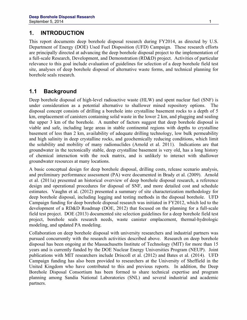
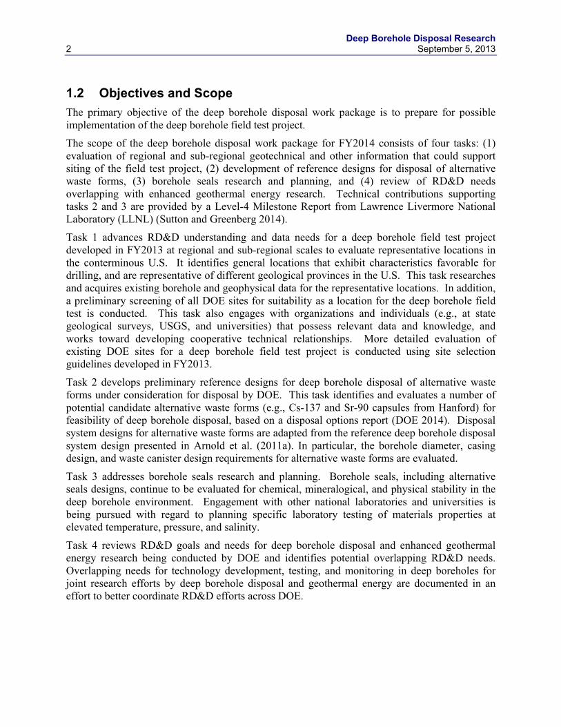
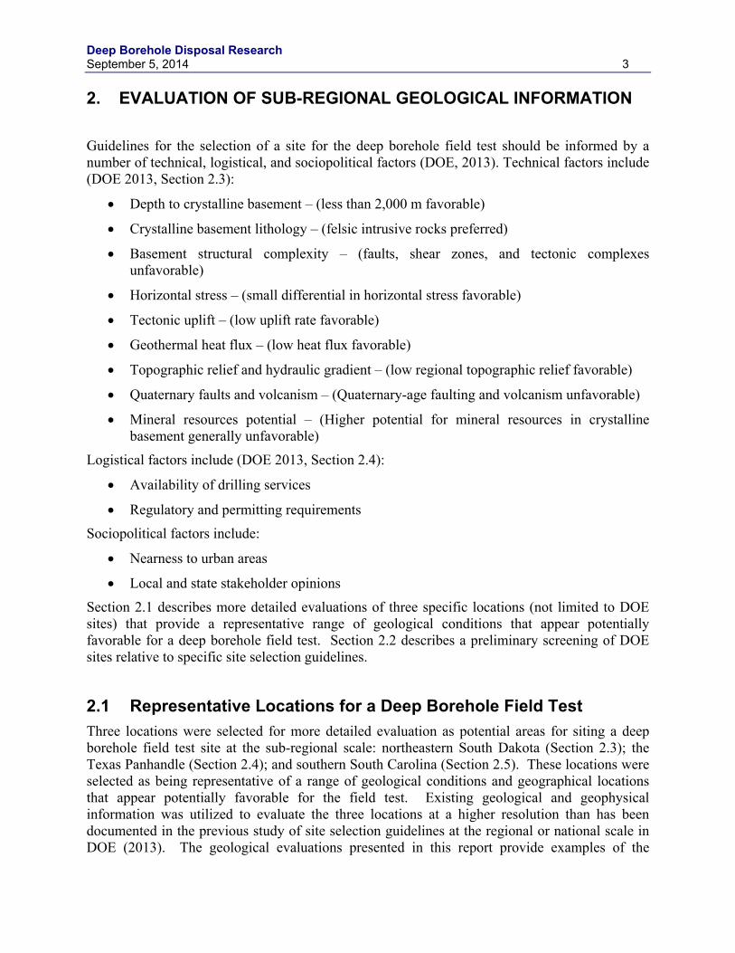
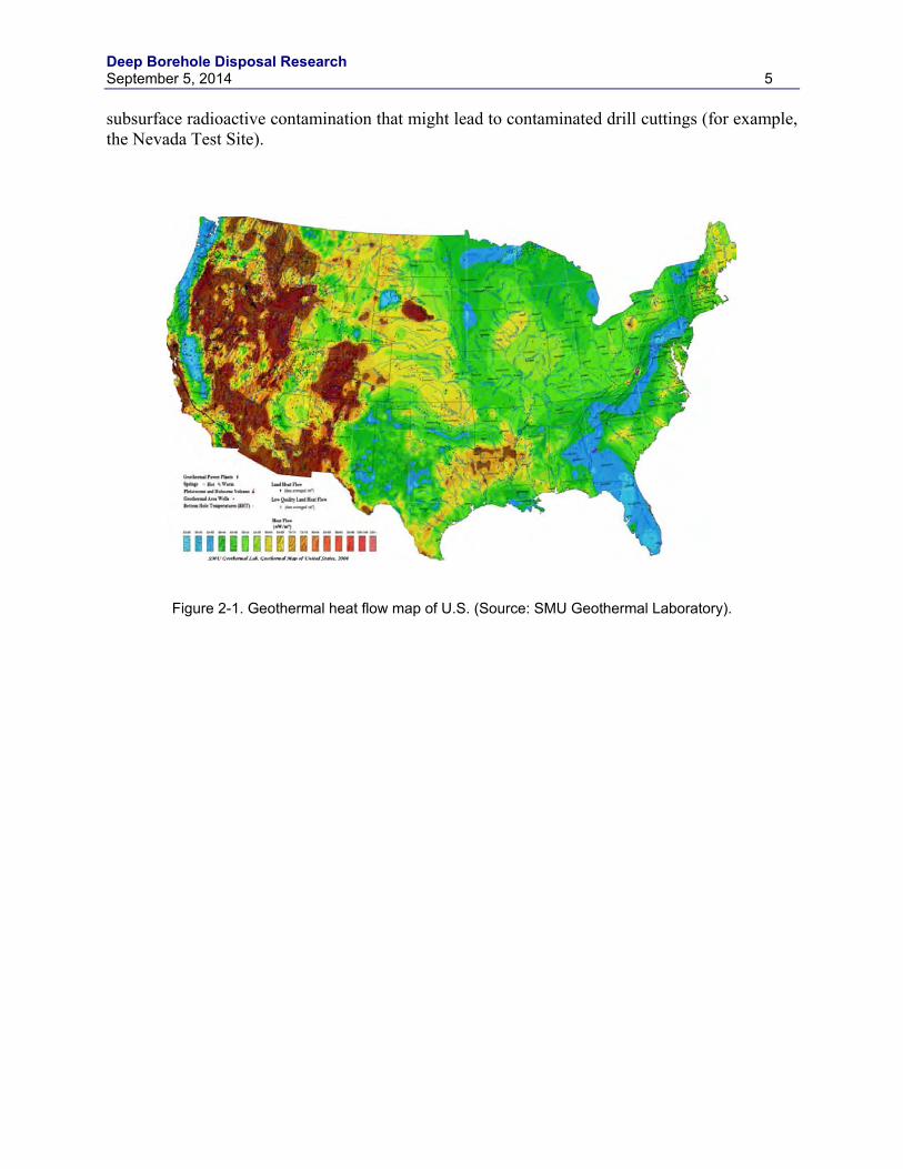
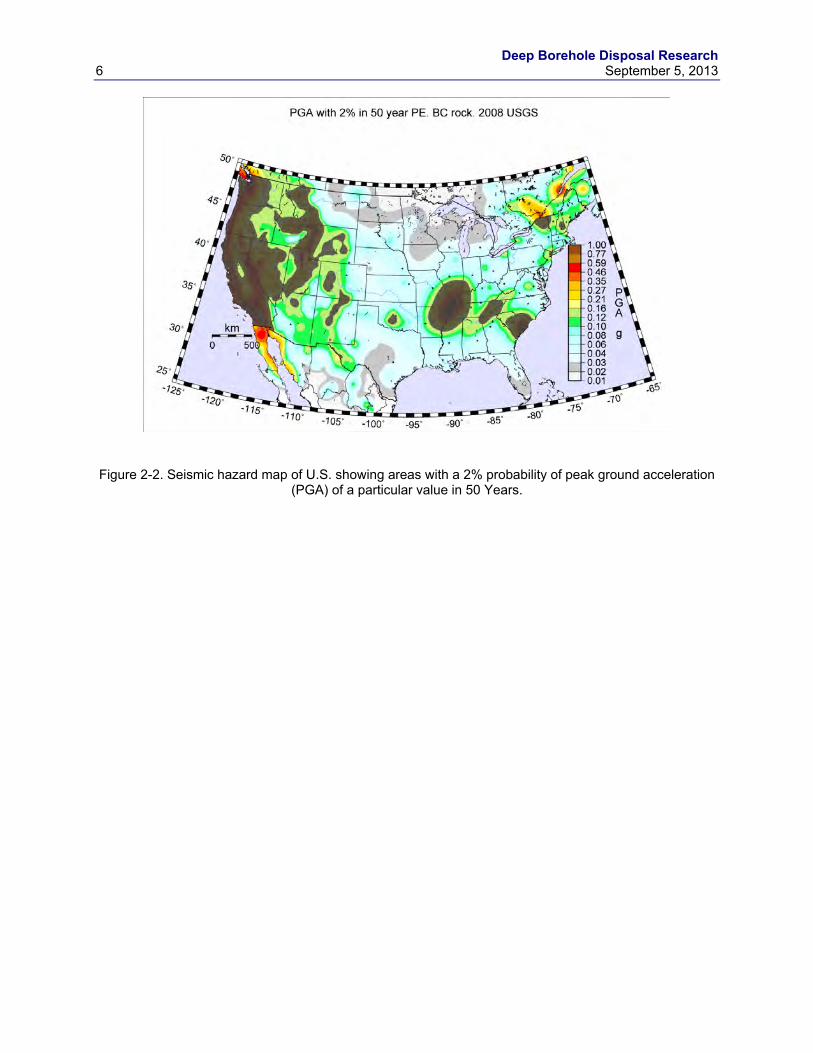
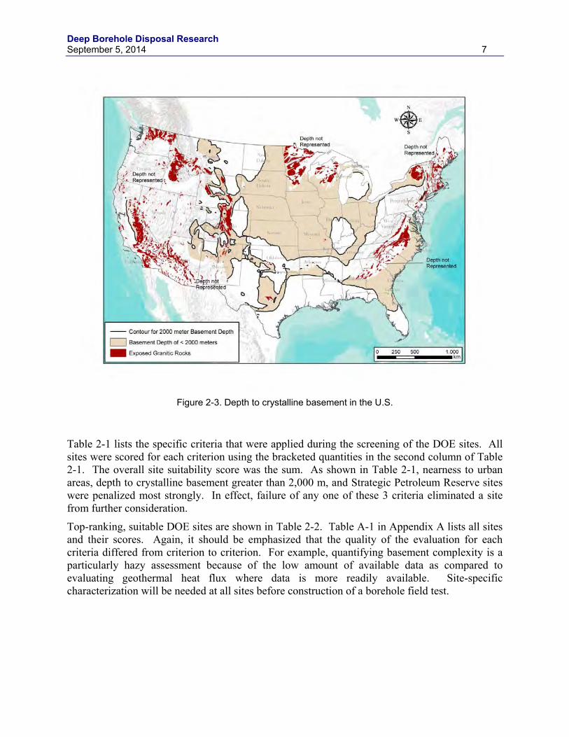
A list of DOE sites was compiled, screened, and ranked on the basis of such factors as: nearness to large population centers, presence of high heat flow (Figure 2-1), recent faulting and/or seismicity (Figure 2-2), high topographic relief, availability of crystalline basement within 2,000 m of the surface (Figure 2-3), and available area greater than 1 km2. While a deep borehole field test using surrogate canisters that do not contain any radioactive waste poses little radiochemical threat, the potential nuisance factor of drilling operations was used to eliminate populated areas from consideration and to assure sufficient area for drilling operations (> 1 km2). Sites with high heat flow might have thermally-driven upward circulating fluids at depth. Recent faulting and earthquakes pose potential problems for borehole stability. Areas with high topographic relief are more likely to have increased fluid circulation at depth. Crystalline basement must be present within 2 km of the surface at the field test site. Strategic Petroleum Reserve Sites were eliminated from the list, as were sites with high oil and gas drilling activity, or existing
Deep Borehole Disposal Research September 5, 2014 5
subsurface radioactive contamination that might lead to contaminated drill cuttings (for example, the Nevada Test Site).
Figure 2-1. Geothermal heat flow map of U.S. (Source: SMU Geothermal Laboratory).
Deep Borehole Disposal Research 6 September 5, 2013
Figure 2-2. Seismic hazard map of U.S. showing areas with a 2% probability of peak ground acceleration
(PGA) of a particular value in 50 Years.
Deep Borehole Disposal Research September 5, 2014 7
Figure 2-3. Depth to crystalline basement in the U.S.
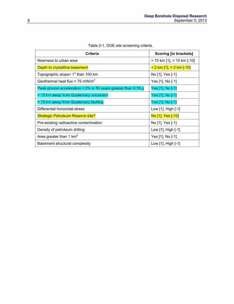
Table 2-1 lists the specific criteria that were applied during the screening of the DOE sites. All sites were scored for each criterion using the bracketed quantities in the second column of Table 2-1. The overall site suitability score was the sum. As shown in Table 2-1, nearness to urban areas, depth to crystalline basement greater than 2,000 m, and Strategic Petroleum Reserve sites were penalized most strongly. In effect, failure of any one of these 3 criteria eliminated a site from further consideration.
Top-ranking, suitable DOE sites are shown in Table 2-2. Table A-1 in Appendix A lists all sites and their scores. Again, it should be emphasized that the quality of the evaluation for each criteria differed from criterion to criterion. For example, quantifying basement complexity is a particularly hazy assessment because of the low amount of available data as compared to evaluating geothermal heat flux where data is more readily available. Site-specific characterization will be needed at all sites before construction of a borehole field test.
Deep Borehole Disposal Research 8 September 5, 2013
Table 2-1. DOE site screening criteria.
Criteria Scoring [in brackets]
Nearness to urban area > 10 km [1], < 10 km [-10]
Depth to crystalline basement < 2 km [1], > 2 km [-10]
Topographic slope> 1o than 100 km No [1], Yes [-1]
Geothermal heat flux < 75 mW/m2 Yes [1], No [-1]
Peak ground acceleration < 2% in 50 years greater than 0.16 g Yes [1], No [-1]
> 10 km away from Quaternary volcanism Yes [1], No [-1]
> 10 km away from Quaternary faulting Yes [1], No [-1]
Differential horizontal stress Low [1], High [-1]
Strategic Petroleum Reserve site? No [1], Yes [-10]
Pre-existing radioactive contamination No [1], Yes [-1]
Density of petroleum drilling Low [1], High [-1]
Area greater than 1 km2 Yes [1], No [-1]
Basement structural complexity Low [1], High [-1]
Deep Borehole Disposal Research September 5, 2014 9
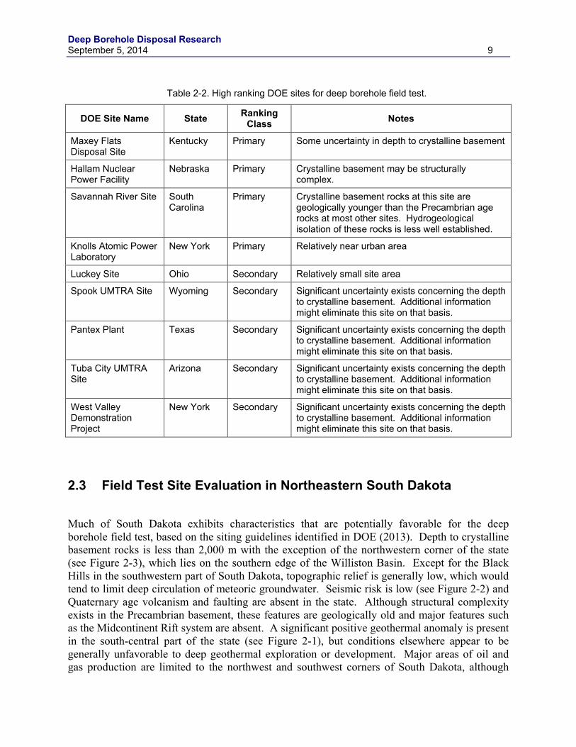
Table 2-2. High ranking DOE sites for deep borehole field test.
DOE Site Name State Ranking Class Notes
Maxey Flats Disposal Site
Kentucky Primary Some uncertainty in depth to crystalline basement
Hallam Nuclear Power Facility
Nebraska Primary Crystalline basement may be structurally complex.
Savannah River Site South Carolina
Primary Crystalline basement rocks at this site are geologically younger than the Precambrian age rocks at most other sites. Hydrogeological isolation of these rocks is less well established.
Knolls Atomic Power Laboratory
New York Primary Relatively near urban area
Luckey Site Ohio Secondary Relatively small site area
Spook UMTRA Site Wyoming Secondary Significant uncertainty exists concerning the depth to crystalline basement. Additional information might eliminate this site on that basis.
Pantex Plant Texas Secondary Significant uncertainty exists concerning the depth to crystalline basement. Additional information might eliminate this site on that basis.
Tuba City UMTRA Site
Arizona Secondary Significant uncertainty exists concerning the depth to crystalline basement. Additional information might eliminate this site on that basis.
West Valley Demonstration Project
New York Secondary Significant uncertainty exists concerning the depth to crystalline basement. Additional information might eliminate this site on that basis.
2.3 Field Test Site Evaluation in Northeastern South Dakota
Much of South Dakota exhibits characteristics that are potentially favorable for the deep borehole field test, based on the siting guidelines identified in DOE (2013). Depth to crystalline basement rocks is less than 2,000 m with the exception of the northwestern corner of the state (see Figure 2-3), which lies on the southern edge of the Williston Basin. Except for the Black Hills in the southwestern part of South Dakota, topographic relief is generally low, which would tend to limit deep circulation of meteoric groundwater. Seismic risk is low (see Figure 2-2) and Quaternary age volcanism and faulting are absent in the state. Although structural complexity exists in the Precambrian basement, these features are geologically old and major features such as the Midcontinent Rift system are absent. A significant positive geothermal anomaly is present in the south-central part of the state (see Figure 2-1), but conditions elsewhere appear to be generally unfavorable to deep geothermal exploration or development. Major areas of oil and gas production are limited to the northwest and southwest corners of South Dakota, although
Deep Borehole Disposal Research 10 September 5, 2013
scattered petroleum exploration drilling has occurred throughout the state. The location of the state in the stable continental interior and the geological data indicate a tectonically quiescent environment.
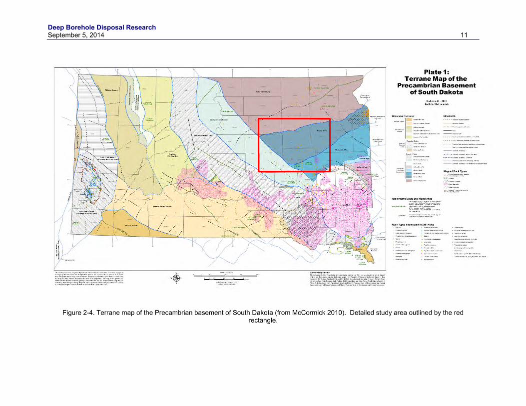
Information on the Precambrian basement in South Dakota is relatively abundant considering that sedimentary rocks obscure the crystalline rocks over the great majority of the state. Figure 2-4 shows the locations where boreholes have intercepted the crystalline basement and the rock types encountered, as well as geological interpretation of large-scale geological terranes in the Precambrian (McCormick 2010). “Terranes” refer to areas within the Precambrian basement with similar geological histories and are further subdivided into sub-provinces and “Blocks” that are relatively intact portions of the crust that lie within major structural boundaries. Interpretation of these Precambrian terranes is informed by larger-scale conceptual models of the tectonic history of North America, age dating of basement rocks over large areas of the central continent, and discontinuities in geophysical surveys that are interpreted to represent major faults and suture zones in the crystalline basement.
The Archean Superior Craton occurs in the Precambrian basement of eastern South Dakota and consists of rocks that have been modified little by collision with the Wyoming Craton to the west or by accretion of island arc rocks of the Yavapai Orogeny to the south (McCormick 2010). Rocks of the Superior Craton are lithologically diverse and generally represent deep seated orogenic geologic conditions. The Archean age of these cratonic rocks differentiate them from the significantly younger Proterozoic age rocks of the Yavapai Orogeny, which are generally of shallower crustal origin and include significant volumes of volcanic rocks.
The area that was chosen for more detailed geological evaluation is located in the northeastern part of South Dakota, as shown by the red rectangle in Figure 2-4. The crystalline basement is generally less than 1,000 m deep in this area (Figure 2-5), which results in a higher resolution geophysical signature of the buried Precambrian terrane, thus aiding in the delineation of basement features. There are also numerous boreholes that have penetrated the Precambrian basement. Archean age basement rocks in this area also represent a longer period of geological stability and have a higher probability of exhibiting characteristics favorable for deep borehole disposal safety. The Benson Block within this area is of particular interest because of a preponderance of granite in borehole samples and geophysical evidence of large granite plutons within this Block.
Deep Borehole Disposal Research September 5, 2014 11
Figure 2-4. Terrane map of the Precambrian basement of South Dakota (from McCormick 2010). Detailed study area outlined by the red rectangle.
Deep Borehole Disposal Research 12 September 5, 2014
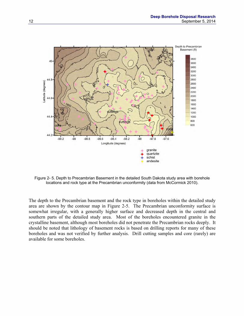
Figure 2- 5. Depth to Precambrian Basement in the detailed South Dakota study area with borehole locations and rock type at the Precambrian unconformity (data from McCormick 2010).
The depth to the Precambrian basement and the rock type in boreholes within the detailed study area are shown by the contour map in Figure 2-5. The Precambrian unconformity surface is somewhat irregular, with a generally higher surface and decreased depth in the central and southern parts of the detailed study area. Most of the boreholes encountered granite in the crystalline basement, although most boreholes did not penetrate the Precambrian rocks deeply. It should be noted that lithology of basement rocks is based on drilling reports for many of these boreholes and was not verified by further analysis. Drill cutting samples and core (rarely) are available for some boreholes.
Deep Borehole Disposal Research September 5, 2014 13
Figure 2- 6. Topographic and Precambrian basement surfaces in the detailed South Dakota study area, with borehole locations (data from McCormick 2010). Elevation is given in feet above mean sea level.
Figure 2-6 is a perspective surface plot of the topographic and Precambrian basement surfaces in the detailed study area. The shaded contour plot of the crystalline basement surface gives an indication of the relief on the unconformity and indicates the erosional nature of this buried topographic surface. The surface topography shown above the basement surface varies by several hundred feet and is dominated by the James River valley, which crosses the detailed study area from north to south. The river valley was formed by the James lobe of the Laurentide glacier during the Pleistocene. The depth from the land surface to the Precambrian basement is fairly well constrained by the existing data.
Deep Borehole Disposal Research 14 September 5, 2014
Figure 2- 7. Aeromagnetic data projected onto the topographic surface and Precambrian basement surface geologic interpretation in the South Dakota detailed study area, with borehole locations (data from
McCormick 2010 and Kucks and Hill 2002).
Figure 2-7 shows the aeromagnetic data from Kucks and Hill (2002) projected onto the topographic surface overlying the crystalline basement surface. The geologic interpretation of the Precambrian terranes from McCormick (2010) is superimposed on the basement surface plot. The general boundaries of the Benson Block in the Precambrian basement are roughly defined by the larger area of irregular higher magnetic signal. The western boundary of the Benson block is a major northwest trending fault or shear zone. The northern and southern boundaries of the Benson block have been interpreted as northerly dipping thrust faults (McCormick 2010). The positive magnetic anomaly in the Benson block may be related to magnetite-bearing granite bodies in the crystalline basement.
Deep Borehole Disposal Research September 5, 2014 15
Figure 2- 8. Gravity data projected onto the topographic surface and Precambrian basement surface geologic interpretation in the South Dakota detailed study area, with borehole locations (data from
McCormick 2010 and Kucks and Hill 2002).
Figure 2-8 shows the isostatic residual gravity anomaly data from Kucks and Hill (2002) projected onto the topographic surface overlying the crystalline basement surface. The isostatic residual gravity anomaly is calculated by subtracting long-wavelength anomalies from the gravity data to correct for isostatic compensation to variations in topographic load on the crust. The isostatic residual gravity anomaly map is assumed to more clearly show variations in density within the upper crust than the uncorrected gravity data. The isostatic residual gravity map shows significant contrast in the gravity field across the major shear zone to the southwest of the Benson Block. The two elliptical areas of high isostatic residual gravity within the Benson Block have been interpreted as potentially two large, high-density granite batholiths (McCormick 2010). These geophysical anomalies may correspond to large deep-seated granite plutons that are similar in size and nature to those that are visible in outcrop elsewhere in the Superior Craton to the north and east of this area.
Deep Borehole Disposal Research 16 September 5, 2014
Figure 2- 9. Generalized stratigraphic column of geologic units in Spink County, South Dakota (from Tomhave 1997).
The generalized sedimentary stratigraphic section overlying the crystalline basement, as exemplified in Spink County in the detailed study area is shown in Figure 2-9. This sedimentary section formed in the broad Cretaceous age Western Interior Seaway and is dominated by shales and mudstones of the Pierre Shale, Carlisle Shale, and Graneros Shale. These shale rock units generally have very low permeability and would be expected to behave as aquitards in the groundwater flow system. The Dakota Formation consists primarily of sandstone, probably has significant transmissivity, and has been exploited as an aquifer in some places in the central and northern Midwest. However, within the detailed study area the Dakota Formation occurs
Deep Borehole Disposal Research September 5, 2014 17
relatively deeply in the stratigraphic section and there is no indication that it is used as a groundwater source. Overall, the sedimentary section in this area probably forms an effective seal to vertical meteoric groundwater flow into or out of the crystalline basement rocks.
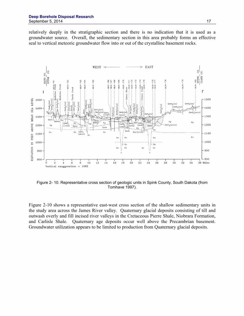
Figure 2- 10. Representative cross section of geologic units in Spink County, South Dakota (from Tomhave 1997).
Figure 2-10 shows a representative east-west cross section of the shallow sedimentary units in the study area across the James River valley. Quaternary glacial deposits consisting of till and outwash overly and fill incised river valleys in the Cretaceous Pierre Shale, Niobrara Formation, and Carlisle Shale. Quaternary age deposits occur well above the Precambrian basement. Groundwater utilization appears to be limited to production from Quaternary glacial deposits.
Deep Borehole Disposal Research 18 September 5, 2014
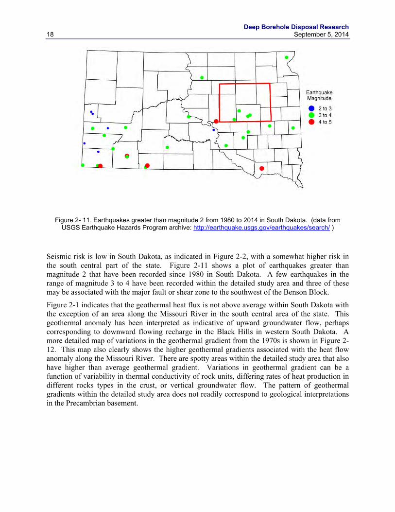
Figure 2- 11. Earthquakes greater than magnitude 2 from 1980 to 2014 in South Dakota. (data from USGS Earthquake Hazards Program archive: http://earthquake.usgs.gov/earthquakes/search/ )
Seismic risk is low in South Dakota, as indicated in Figure 2-2, with a somewhat higher risk in the south central part of the state. Figure 2-11 shows a plot of earthquakes greater than magnitude 2 that have been recorded since 1980 in South Dakota. A few earthquakes in the range of magnitude 3 to 4 have been recorded within the detailed study area and three of these may be associated with the major fault or shear zone to the southwest of the Benson Block.
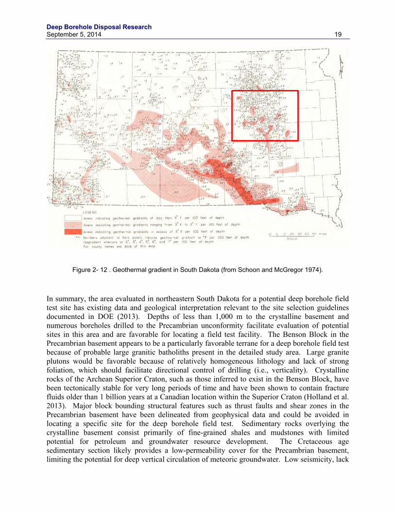
Figure 2-1 indicates that the geothermal heat flux is not above average within South Dakota with the exception of an area along the Missouri River in the south central area of the state. This geothermal anomaly has been interpreted as indicative of upward groundwater flow, perhaps corresponding to downward flowing recharge in the Black Hills in western South Dakota. A more detailed map of variations in the geothermal gradient from the 1970s is shown in Figure 2-12. This map also clearly shows the higher geothermal gradients associated with the heat flow anomaly along the Missouri River. There are spotty areas within the detailed study area that also have higher than average geothermal gradient. Variations in geothermal gradient can be a function of variability in thermal conductivity of rock units, differing rates of heat production in different rocks types in the crust, or vertical groundwater flow. The pattern of geothermal gradients within the detailed study area does not readily correspond to geological interpretations in the Precambrian basement.
Deep Borehole Disposal Research September 5, 2014 19
Figure 2- 12 . Geothermal gradient in South Dakota (from Schoon and McGregor 1974).
In summary, the area evaluated in northeastern South Dakota for a potential deep borehole field test site has existing data and geological interpretation relevant to the site selection guidelines documented in DOE (2013). Depths of less than 1,000 m to the crystalline basement and numerous boreholes drilled to the Precambrian unconformity facilitate evaluation of potential sites in this area and are favorable for locating a field test facility. The Benson Block in the Precambrian basement appears to be a particularly favorable terrane for a deep borehole field test because of probable large granitic batholiths present in the detailed study area. Large granite plutons would be favorable because of relatively homogeneous lithology and lack of strong foliation, which should facilitate directional control of drilling (i.e., verticality). Crystalline rocks of the Archean Superior Craton, such as those inferred to exist in the Benson Block, have been tectonically stable for very long periods of time and have been shown to contain fracture fluids older than 1 billion years at a Canadian location within the Superior Craton (Holland et al. 2013). Major block bounding structural features such as thrust faults and shear zones in the Precambrian basement have been delineated from geophysical data and could be avoided in locating a specific site for the deep borehole field test. Sedimentary rocks overlying the crystalline basement consist primarily of fine-grained shales and mudstones with limited potential for petroleum and groundwater resource development. The Cretaceous age sedimentary section likely provides a low-permeability cover for the Precambrian basement, limiting the potential for deep vertical circulation of meteoric groundwater. Low seismicity, lack
Deep Borehole Disposal Research 20 September 5, 2014
of Quaternary age faults and volcanic rocks, and low to moderate geothermal gradient within the detailed study area all appear to be favorable factors for locating a field test in this area.
2.4 Field Test Site Evaluation in the Texas Panhandle
Parts of the Texas Panhandle have geological characteristics that are favorable for siting the deep borehole field test, although several geological factors are highly variable within this subregion. The DOE owned Pantex Plant site is a location of particular interest and the evaluation of conditions in the Texas Panhandle is focused on that location. Regional scale mapping of the depth to crystalline basement in the Texas Panhandle indicates depths from less than 500 m to greater than 7,000 m across this area. Important structural features influencing the depth to Precambrian rocks include the Anadarko Basin in the northeastern part of the Panhandle, the Palo Duro Basin in the southern part of the Panhandle, the Dalhart Basin in the northwestern part, the Amarillo Uplift separating the Anadarko Basin from the Palo Duro Basin, and the Bravo Dome in the western part of the Panhandle. The Amarillo Uplift trends from west northwest to east southeast in the east central part of the Texas Panhandle and is a subsurface western extension of the Wichita Uplift in southwester Oklahoma. The Amarillo Uplift and the adjoining flanks of the Anadarko and Palo Duro Basins appear to be faulted and structurally complex at the depth of the crystalline basement, leading to significant uncertainty in the depth to Precambrian rocks in many areas. Topographic relief and seismic risks are low in this area. Quaternary age faults and volcanism do not occur; however, Quaternary volcanic rocks outcrop in New Mexico just to the northwest of the Panhandle. Geothermal heat flux and temperature gradients are low throughout the Texas Panhandle (see Figure 2-1). Major areas of oil and gas production exist along the Amarillo Uplift and within the Anadarko Basin, with scattered petroleum exploration drilling and production elsewhere in the other sedimentary basins of the Texas Panhandle. The location within the stable continental interior, inactive nature of the sedimentary basins, and low seismicity indicate that the Texas Panhandle is a tectonically stable area.
Deep Borehole Disposal Research September 5, 2014 21
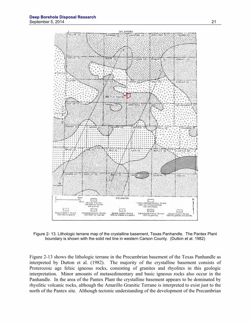
Figure 2- 13. Lithologic terrane map of the crystalline basement, Texas Panhandle. The Pantex Plant boundary is shown with the solid red line in western Carson County. (Dutton et al. 1982)
Figure 2-13 shows the lithologic terrane in the Precambrian basement of the Texas Panhandle as interpreted by Dutton et al. (1982). The majority of the crystalline basement consists of Proterozoic age felsic igneous rocks, consisting of granites and rhyolites in this geologic interpretation. Minor amounts of metasedimentary and basic igneous rocks also occur in the Panhandle. In the area of the Pantex Plant the crystalline basement appears to be dominated by rhyolitic volcanic rocks, although the Amarillo Granitic Terrane is interpreted to exist just to the north of the Pantex site. Although tectonic understanding of the development of the Precambrian
Deep Borehole Disposal Research 22 September 5, 2014
basement in this area is ongoing, these rocks seem to be associated with accretionary growth of the North American continent by island arc magmatism across the central and southwestern U.S. This style of crustal formation tends to result in voluminous felsic volcanic rocks, small to medium sized granitic plutons, and volcaniclastic sedimentary and metamorphics rocks. These terranes are likely more lithologically variable than deep seated orogenic terranes, such as the Superior Craton. Information on lithology, drill cuttings, and core from individual boreholes that have penetrated the crystalline basement may be available, but are not readily available from public sources.
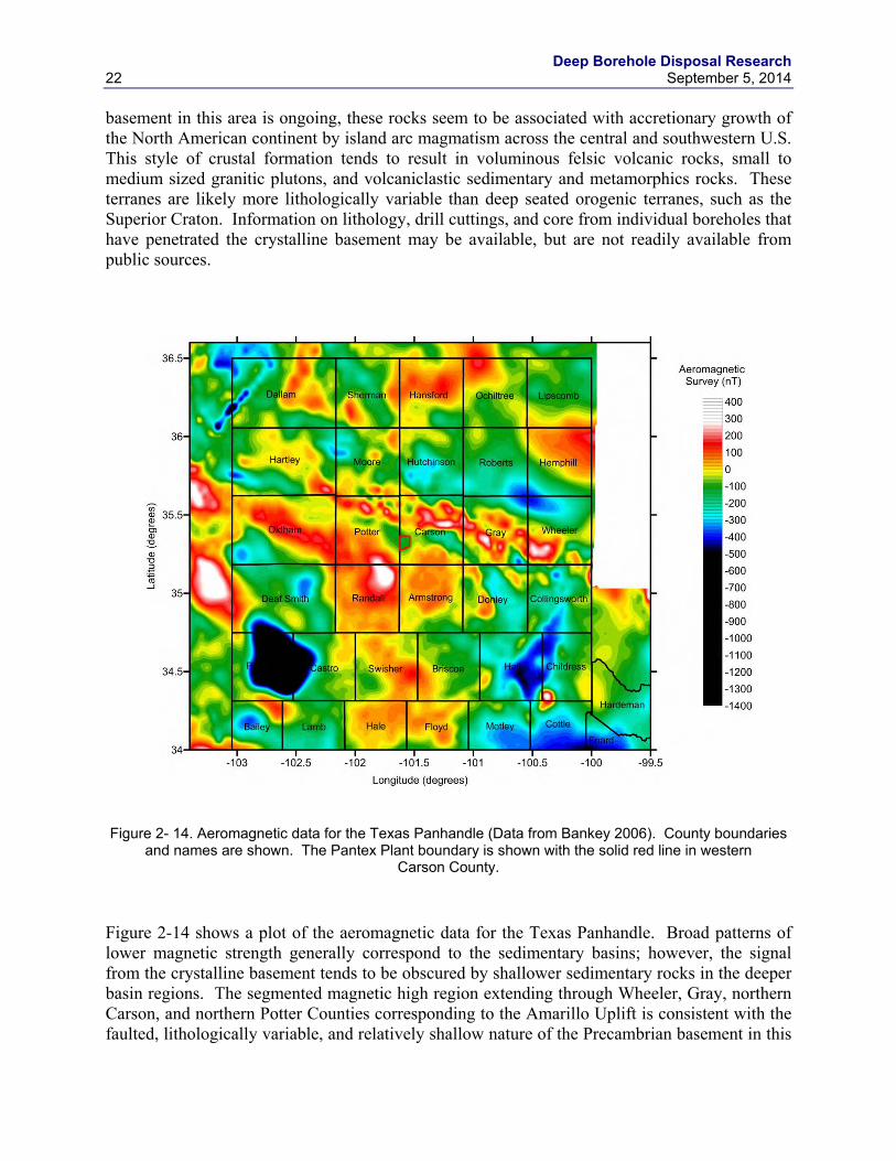
Figure 2- 14. Aeromagnetic data for the Texas Panhandle (Data from Bankey 2006). County boundaries
and names are shown. The Pantex Plant boundary is shown with the solid red line in western Carson County.
Figure 2-14 shows a plot of the aeromagnetic data for the Texas Panhandle. Broad patterns of lower magnetic strength generally correspond to the sedimentary basins; however, the signal from the crystalline basement tends to be obscured by shallower sedimentary rocks in the deeper basin regions. The segmented magnetic high region extending through Wheeler, Gray, northern Carson, and northern Potter Counties corresponding to the Amarillo Uplift is consistent with the faulted, lithologically variable, and relatively shallow nature of the Precambrian basement in this
Deep Borehole Disposal Research September 5, 2014 23
region. Note that the Pantex Plant site lies within a northwest-southeast trending zone of lower magnetic strength. This is consistent with structural interpretation of drilling data by Dutton et al. (1982) that a downdropped, fault bounded block of the Precambrian basement adjacent to the Amarillo Uplift exists in the subsurface in this area (see Figure 2-16). No clear correspondence exists between the aeromagnetic map and the lithologic interpretation of the crystalline basement shown in Figure 2-13. This may be due to the greater depth to the basement rocks over much of the Texas Panhandle, a lack of variation in magnetic strength among the rock types in the crystalline basement, or a combination of both factors.
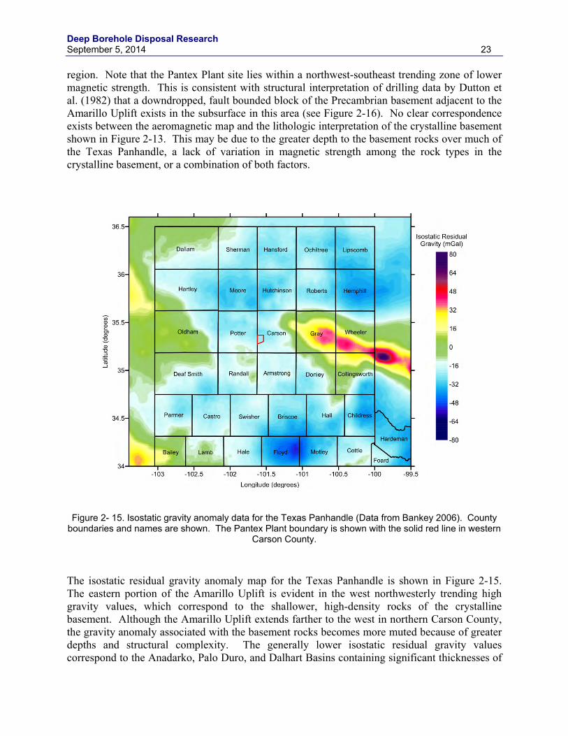
Figure 2- 15. Isostatic gravity anomaly data for the Texas Panhandle (Data from Bankey 2006). County
boundaries and names are shown. The Pantex Plant boundary is shown with the solid red line in western Carson County.
The isostatic residual gravity anomaly map for the Texas Panhandle is shown in Figure 2-15. The eastern portion of the Amarillo Uplift is evident in the west northwesterly trending high gravity values, which correspond to the shallower, high-density rocks of the crystalline basement. Although the Amarillo Uplift extends farther to the west in northern Carson County, the gravity anomaly associated with the basement rocks becomes more muted because of greater depths and structural complexity. The generally lower isostatic residual gravity values correspond to the Anadarko, Palo Duro, and Dalhart Basins containing significant thicknesses of
Deep Borehole Disposal Research 24 September 5, 2014
lower-density sedimentary rocks. The intermediate gravity values in western Oldham and northern Deaf Smith Counties delineate the broad area of shallower depth to the Precambrian basement of Bravo Dome. The moderately low isostatic residual gravity values at the Pantex Plant site are consistent with the geological interpretation of Dutton et al. (1982) of a structural low in the Precambrian unconformity in this area.
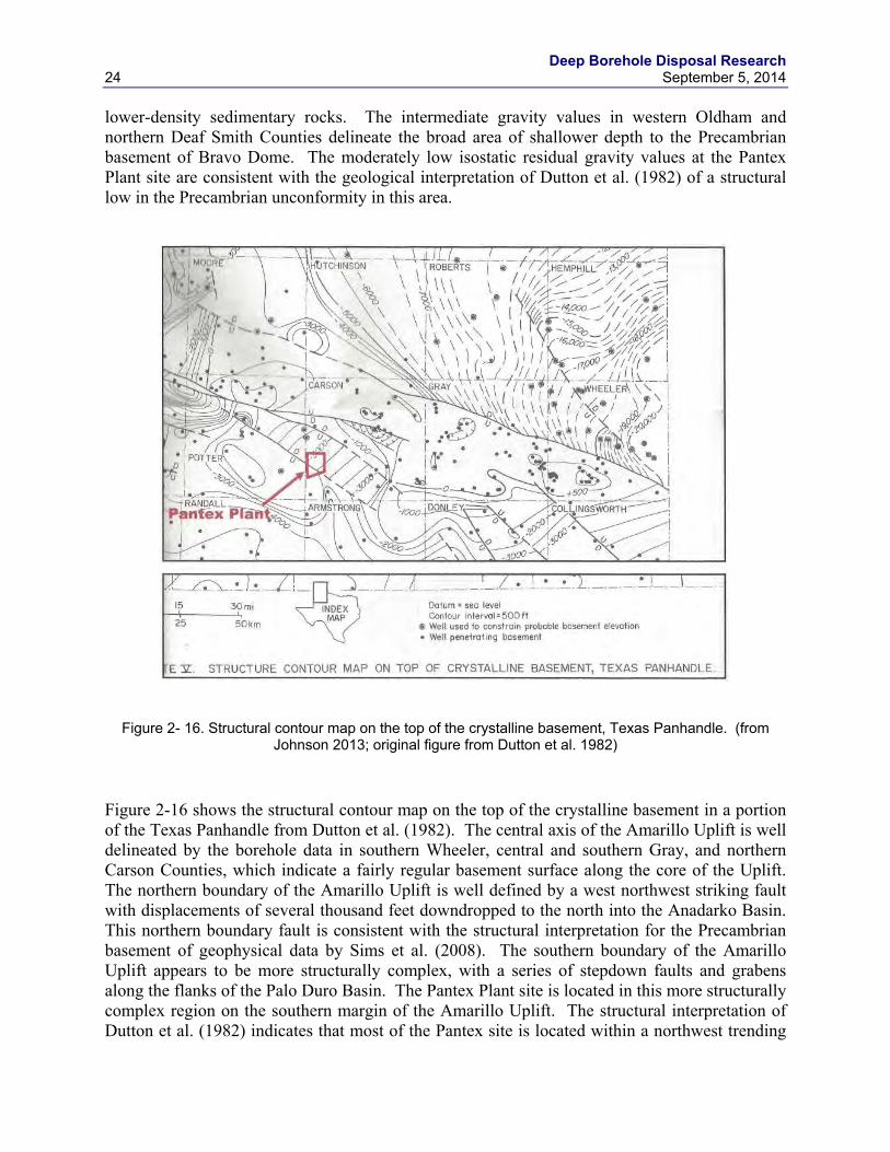
Figure 2- 16. Structural contour map on the top of the crystalline basement, Texas Panhandle. (from Johnson 2013; original figure from Dutton et al. 1982)
Figure 2-16 shows the structural contour map on the top of the crystalline basement in a portion of the Texas Panhandle from Dutton et al. (1982). The central axis of the Amarillo Uplift is well delineated by the borehole data in southern Wheeler, central and southern Gray, and northern Carson Counties, which indicate a fairly regular basement surface along the core of the Uplift. The northern boundary of the Amarillo Uplift is well defined by a west northwest striking fault with displacements of several thousand feet downdropped to the north into the Anadarko Basin. This northern boundary fault is consistent with the structural interpretation for the Precambrian basement of geophysical data by Sims et al. (2008). The southern boundary of the Amarillo Uplift appears to be more structurally complex, with a series of stepdown faults and grabens along the flanks of the Palo Duro Basin. The Pantex Plant site is located in this more structurally complex region on the southern margin of the Amarillo Uplift. The structural interpretation of Dutton et al. (1982) indicates that most of the Pantex site is located within a northwest trending
Deep Borehole Disposal Research September 5, 2014 25
downdropped block, although no data are shown on the site and nearby borehole data are sparse. However, using the map shown in Figure 2-16 the estimated depth to crystalline basement varies from about 6,400 ft (1,960 m) in the southwest corner of the site to about 8,700 ft (2,650 m) in the northwest corner. This places the crystalline basement at the Pantex site near or deeper than the maximum favorable depth for the deep borehole field test of 2,000 m. It should be noted that there is considerable uncertainty in these estimated depths to crystalline basement. In addition, faulting and structural uncertainty likely exist at the surface of the Precambrian basement at the location of the Pantex Plant.
Figure 2- 17. Earthquakes greater than magnitude 2 from 1979 to 2014 in the Texas Panhandle. (data from USGS Earthquake Hazards Program archive: http://earthquake.usgs.gov/earthquakes/search/ )
Recorded earthquakes in the Texas Panhandle from 1979 to 2014 are plotted on the map shown in Figure 2-17. Seismicity and seismic risk are low in the Texas Panhandle, indicating general tectonic stability. Low magnitude earthquakes do seem more numerous along and near the Amarillo Uplift and Bravo Dome than in the adjoining sedimentary basins and may be related to movement in the crystalline basement. There appears to be a cluster of higher density seismicity in Potter County to the west of the Pantex Site, which may be associated with faulting on the southern margin of the Amarillo Uplift near its western end (see Figure 2-16).
Deep Borehole Disposal Research 26 September 5, 2014
Figure 2- 18. Temperature at 10,000 feet (3050 m) depth in Texas (from Frontier Associates 2008).
Geothermal heat flux and geothermal gradients are generally low in the Texas Panhandle (see Figure 2-1), as reflected by the plot of estimated temperatures at a depth of 10,000 ft (3050 m) in Figure 2-18. There is little potential for geothermal resource exploration or development in the deep subsurface in this area and ambient temperatures at the depth of the deep borehole field test would not be unmanageably high.
The sedimentary cover over the crystalline basement in the Texas Panhandle is highly variable in thickness and stratigraphy, and detailed discussion of this topic is beyond the scope of this report. Sedimentary sections include siliciclastic, carbonate, and evaporite units that generally thin over the structural arches. Some areas, particularly in the western Texas panhandle, have depths to the crystalline basement of less than 2,000 m and evaporite beds in the overlying sedimentary section. Evaporites have very low permeability and probably form extremely effective barriers to vertical groundwater flow where they remain intact. Evaporites also have the potential to behave as a self-sealing mechanism in boreholes if the casing is removed and the depth is great enough to induce plastic behavior in the salt.
In conclusion, several factors are favorable for siting the deep borehole field test in the Texas Panhandle. Low topographic relief, general tectonic stability, and low geothermal heat flux are favorable characteristics for deep borehole disposal. Sufficient subsurface data are available to
Deep Borehole Disposal Research September 5, 2014 27
determine the depths to crystalline basement in a general sense and the margins of major sedimentary basins. However, many areas with depth to crystalline basement rocks of less than 2,000 m along the major structural arches are highly faulted and there is significant uncertainty in the elevation of the crystalline basement away from existing boreholes that have penetrated the Precambrian unconformity. In particular, the Pantex Plant site is located on the southern margin of the Amarillo Uplift in an area with a faulted structural trough in the Precambrian basement, little nearby borehole data, and significant uncertainty in depth to the crystalline basement. There are areas to the north and east of the Pantex site (northern Carson and central Gray Counties) that have depths to the crystalline basement of less than 2,000 m, considerably less uncertainty in depth, and potentially less faulting in the basement rocks. There are also areas over the Bravo Dome in Oldham and Deaf Smith Counties with depths to the Precambrian of less than 2,000 m that might be more favorable to a field test than the Pantex Plant site.
2.5 Field Test Site Evaluation at the Savannah River Site
The Savannah River Site (SRS) in South Carolina is the third area to be evaluated for the deep borehole field test and represents a clear contrast in geological characteristics to northeastern South Dakota and the Texas Panhandle. The Savannah River Site is located near the passive tectonic margin of the North American continent and is underlain by basement rocks of Paleozoic and Mesozoic age, much younger than the Precambrian age rocks in the crystalline basement of central North America. The basement consists of metamorphic and igneous rocks associated with the Alleghanian orogeny in many locations in the Atlantic Coastal Plain, but is also composed of Triassic-Jurassic age sedimentary rocks in some places. The basement unconformity dips to the southeast in a fairly uniform fashion in this area and the depth to the basement is less than 500 m at the SRS. Overlying unconsolidated and semiconsolidated sediments are Cretaceous to Tertiary in age and were deposited in diverse fluvial, deltaic, and marine shelf environments (Denham 1995). Topographic relief is generally low, but the isolation of basement rocks from vertical groundwater circulation is unclear. Geothermal heat flux is moderately low and petroleum potential appears to be low, both favorable factors for deep borehole disposal. Seismic risk is moderately high at the SRS (see Figure 2-2), largely because of proximity to the epicenter of the historical 1886 Charleston earthquake, which had an estimated magnitude of 7.3.
The lithology and faulting of the basement rocks at the SRS have been assessed with a significant number of boreholes, seismic reflection profiling, and other geophysical methods. A generalized interpretation of the lithology in the basement is shown in Figure 2-19. Metamorphic rocks consisting of metavolcanic rocks, mafic and ultramafic rocks, amphibolite, and biotite gneiss occur in the northwestern part of the SRS. The lower grade mafic metamorphic rocks are separated from the higher grade gneisses by a northeast-southwest striking fault. Triassic age clastic sedimentary rocks consisting of coarse grained alluvial fan facies near the Pen Branch Fault (see Figure 2-19) transitioning to finer grained sediments to the southeast (Denham 1995) occur in the southeastern part of the SRS. The clastic sedimentary rocks fill the Dunbarton Basin in the basement, which is interpreted to be an asymmetric rift basin with the greater displacement having occurred along the Pen Branch normal fault. The thickness of clastic sedimentary fill in this rift graben has been estimated to be between 1,700
Deep Borehole Disposal Research 28 September 5, 2014
and 3,700 m (Denham 1995). The locations of major faults in the SRS basement rocks have been confirmed by seismic reflection interpretation (Cumbest et al. 1998). It is important to note that the basement rocks of the SRS are crystalline rocks on the northwest half of the site and non-crystalline rocks in the southeastern part of the site. Crystalline metamorphic rocks probably exist below the sedimentary fill in the Dunbarton Basin, but may occur at depths of greater than 2,000 m, which is a guideline for favorability for the deep borehole field test.
Figure 2- 19. Generalized geologic map of the pre-Cenozoic basement at the Savannah River Site area in
South Carolina. (from Domoracki 1995)
Both felsic and mafic igneous intrusions have been identified in the basement near the SRS based on geophysical surveys (Duff et al. 2013). These include the relatively shallow felsic Graniteville Pluton and a large diabase igneous intrusion to the southeast of the SRS. Inverse modeling of the geophysical data by Duff et al. (2013) indicates that the Graniteville Pluton has an estimated thickness of about 2,500 m and the diabase intrusions are about 2,000 m thick.
Deep Borehole Disposal Research September 5, 2014 29
Figure 2- 20. Aeromagnetic data for the Savannah River Site area in South Carolina. County boundaries
are shown. The SRS boundary is shown with the solid orange line. Boreholes to the crystalline basement shown with open circles. (Data from Daniels 2005)
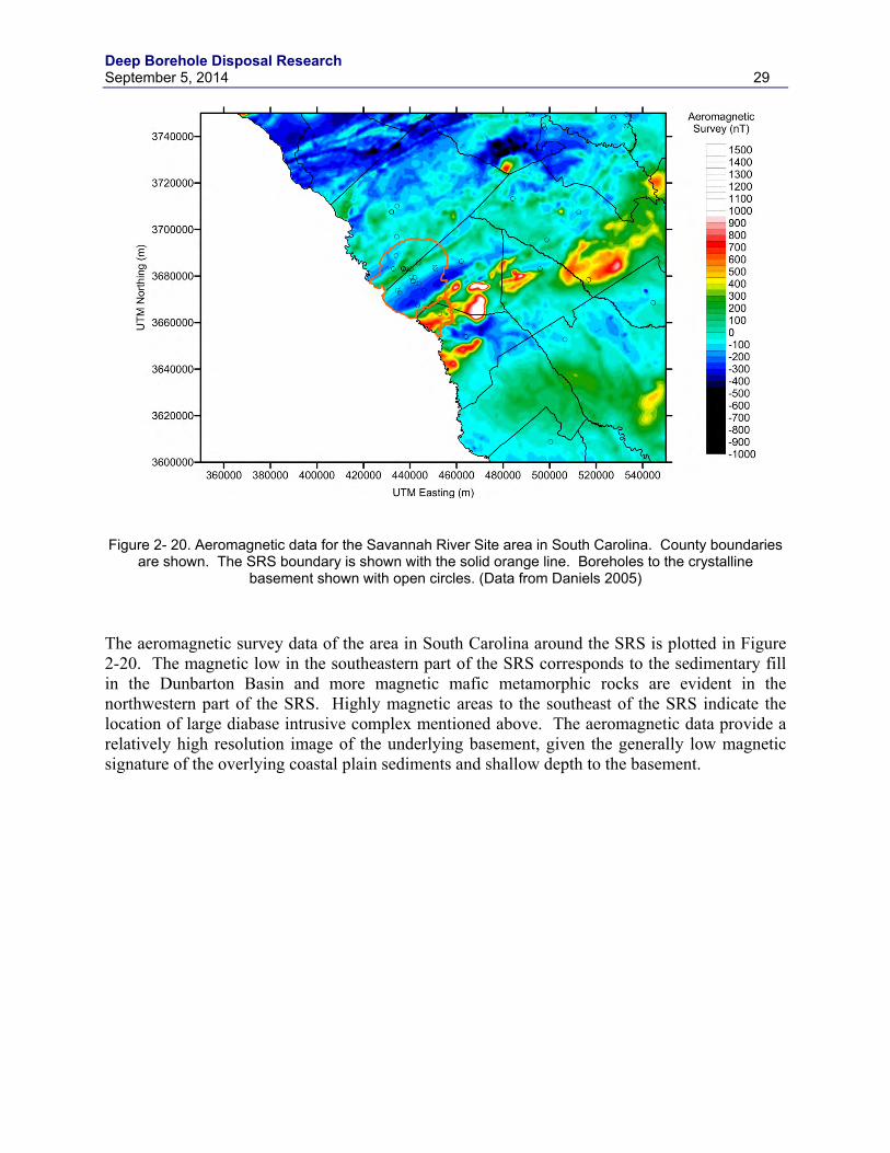
The aeromagnetic survey data of the area in South Carolina around the SRS is plotted in Figure 2-20. The magnetic low in the southeastern part of the SRS corresponds to the sedimentary fill in the Dunbarton Basin and more magnetic mafic metamorphic rocks are evident in the northwestern part of the SRS. Highly magnetic areas to the southeast of the SRS indicate the location of large diabase intrusive complex mentioned above. The aeromagnetic data provide a relatively high resolution image of the underlying basement, given the generally low magnetic signature of the overlying coastal plain sediments and shallow depth to the basement.
Deep Borehole Disposal Research 30 September 5, 2014
Figure 2- 21. Isostatic gravity anomaly data for the Savannah River Site area in South Carolina. County
boundaries are shown. The SRS boundary is shown with the solid orange line. Boreholes to the crystalline basement shown with open circles. (Data from Daniels 2005)
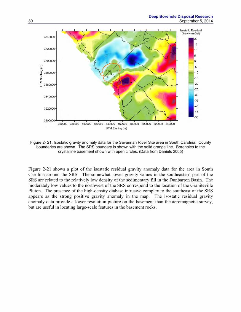
Figure 2-21 shows a plot of the isostatic residual gravity anomaly data for the area in South Carolina around the SRS. The somewhat lower gravity values in the southeastern part of the SRS are related to the relatively low density of the sedimentary fill in the Dunbarton Basin. The moderately low values to the northwest of the SRS correspond to the location of the Graniteville Pluton. The presence of the high-density diabase intrusive complex to the southeast of the SRS appears as the strong positive gravity anomaly in the map. The isostatic residual gravity anomaly data provide a lower resolution picture on the basement than the aeromagnetic survey, but are useful in locating large-scale features in the basement rocks.
Deep Borehole Disposal Research September 5, 2014 31
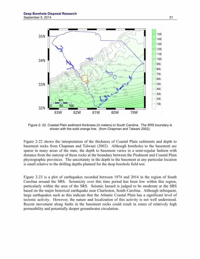
Figure 2- 22. Coastal Plain sediment thickness (in meters) in South Carolina. The SRS boundary is shown with the solid orange line. (from Chapman and Talwani 2002).
Figure 2-22 shows the interpretation of the thickness of Coastal Plain sediments and depth to basement rocks from Chapman and Talwani (2002). Although boreholes to the basement are sparse in many areas of the state, the depth to basement varies in a semi-regular fashion with distance from the outcrop of these rocks at the boundary between the Piedmont and Coastal Plain physiographic provinces. The uncertainty in the depth to the basement at any particular location is small relative to the drilling depths planned for the deep borehole field test.
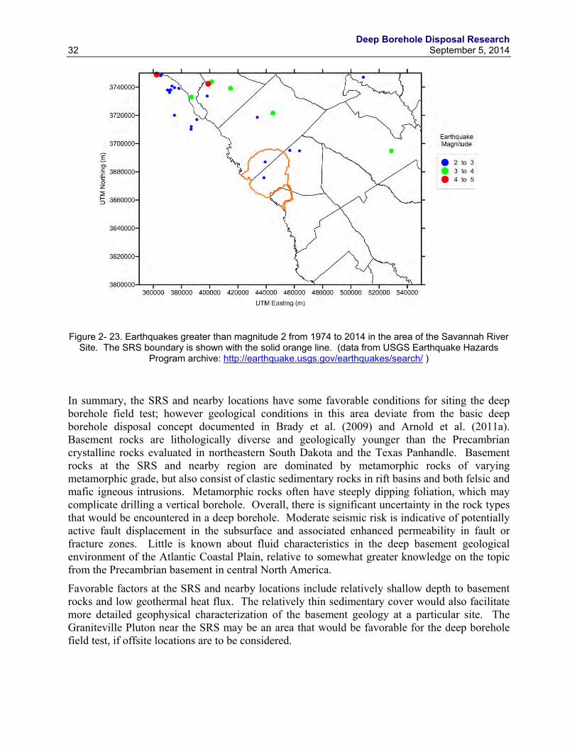
Figure 2-23 is a plot of earthquakes recorded between 1974 and 2014 in the region of South Carolina around the SRS. Seismicity over this time period has been low within this region, particularly within the area of the SRS. Seismic hazard is judged to be moderate at the SRS based on the major historical earthquake near Charleston, South Carolina. Although infrequent, large earthquakes such as this indicate that the Atlantic Coastal Plain has a significant level of tectonic activity. However, the nature and localization of this activity is not well understood. Recent movement along faults in the basement rocks could result in zones of relatively high permeability and potentially deeper groundwater circulation.
Deep Borehole Disposal Research 32 September 5, 2014
Figure 2- 23. Earthquakes greater than magnitude 2 from 1974 to 2014 in the area of the Savannah River
Site. The SRS boundary is shown with the solid orange line. (data from USGS Earthquake Hazards Program archive: http://earthquake.usgs.gov/earthquakes/search/ )
In summary, the SRS and nearby locations have some favorable conditions for siting the deep borehole field test; however geological conditions in this area deviate from the basic deep borehole disposal concept documented in Brady et al. (2009) and Arnold et al. (2011a). Basement rocks are lithologically diverse and geologically younger than the Precambrian crystalline rocks evaluated in northeastern South Dakota and the Texas Panhandle. Basement rocks at the SRS and nearby region are dominated by metamorphic rocks of varying metamorphic grade, but also consist of clastic sedimentary rocks in rift basins and both felsic and mafic igneous intrusions. Metamorphic rocks often have steeply dipping foliation, which may complicate drilling a vertical borehole. Overall, there is significant uncertainty in the rock types that would be encountered in a deep borehole. Moderate seismic risk is indicative of potentially active fault displacement in the subsurface and associated enhanced permeability in fault or fracture zones. Little is known about fluid characteristics in the deep basement geological environment of the Atlantic Coastal Plain, relative to somewhat greater knowledge on the topic from the Precambrian basement in central North America.
Favorable factors at the SRS and nearby locations include relatively shallow depth to basement rocks and low geothermal heat flux. The relatively thin sedimentary cover would also facilitate more detailed geophysical characterization of the basement geology at a particular site. The Graniteville Pluton near the SRS may be an area that would be favorable for the deep borehole field test, if offsite locations are to be considered.
Deep Borehole Disposal Research September 5, 2014 33
3. DISPOSAL SYSTEM DESIGN FOR ALTERNATIVE WASTE FORMS
3.1 Review of Alternative Waste Forms The DOE is evaluating policy options for the management and permanent disposal of a broad range of radioactive waste types, including spent nuclear fuel and high-level radioactive waste (DOE, 2014). Specifically, the strategy for disposal of all waste types in a single geological repository is being reconsidered and disposal alternatives are being analyzed for several classes of radioactive waste. DOE owned radioactive waste forms vary considerably in composition, activity, volume, size, and shape. Such diversity suggests that optimal management of these wastes might involve alternative disposal systems, where waste form characteristics are matched to disposal system attributes.
The DOE (2014) waste options report considers the range of radioactive waste types that exist or are reasonably projected based on current plans and waste treatment technologies. The evaluations in the analysis are primarily qualitative and based on experience with four disposal concepts: mined geological repositories in salt, clay/shale, or crystalline rock; and deep borehole disposal. Total waste volume considered in DOE (2014) is dominated by existing and projected commercial SNF, but also includes a diversity of HLW types and potential waste forms. For the purposes of the waste options report, the various radioactive waste types were divided among ten waste groups with similar radiological, chemical, physical, packaging, and disposal characteristics. The cesium and strontium capsules and the untreated calcine waste discussed later in this section fall into Waste Group 8, consisting of salts, granular solids, and powders.
Results of the DOE (2014) study concluded that any of the mined repository options has the potential to comply with regulatory requirements and protection of the environment, although each of the mined repository options has specific pros and cons regarding implementation and feasibility. The study concludes that applicability of deep borehole disposal is more restricted, primarily due to limitations imposed by existing waste package dimensions and maximum practical deep borehole diameter. Even with size limitations, deep borehole disposal may be suitable for several small waste forms and some wastes that have not yet been packaged. For example, the approximately 1900 cesium and strontium capsules from the Hanford Site could be potentially disposed in a deep borehole. These capsules are in pool storage and contained a total of 67 million curies of radioactive material in 2002. In addition to these Cs-Sr capsules, wastes potentially suitable for disposal in the reference-design borehole include:
1. Calcine wastes at the Idaho National Laboratory (INL). The 4,400 m3 of granular calcine HLW currently stored at INL could be packaged in canisters suitable for deep borehole disposal. Without further treatment, this material will be subject to regulation under the Resource Conservation and Recovery Act (RCRA).
2. Some DOE-managed SNF that has not yet been been packaged into 25.5-inch multicanister overpacks (MCOs) could be packaged for borehole disposal. Total mass is small (less than 50 MTHM) compared with the already packaged N Reactor fuel. Candidate materials include debris and scraps as well as multiple types of smaller intact fuel assemblies.
Deep Borehole Disposal Research 34 September 5, 2014
3. Sodium-bearing wastes at INL. The sodium-bearing waste currently exists as 850,000 gallons of mixed liquids and solids. After treatment by fluidized-bed steam reforming, the granular solid waste could be packaged in canisters suitable for deep borehole disposal. Without further treatment, this material will be subject to regulation under RCRA.
4. Treated sodium-bonded fuels. Projected waste forms from electrometallurgical treatment of the approximately 60 MTHM of sodium-bonded fuel could be engineered to be small enough for deep borehole disposal.
Although the applicability of deep borehole disposal is more restricted than mined repository options, it is noted that deep borehole disposal offers potential advantages regarding confidence in the performance of the natural barrier system, thermal load management, and potential for direct disposal of some waste forms without the need for further waste treatment. Based on the findings of the DOE (2014) study, deep borehole disposal for cesium (Cs-137) and strontium (Sr-90) capsules (Section 3.2) and direct disposal of calcine waste (Section 3.3) were further analyzed in this report.
In addition to the potential waste forms, long-term performance of other engineered components is also important. Section 3.4 describes possible materials and degradation modes for the waste forms, waste canisters, borehole casing.
3.2 Disposal of DOE Cs-137 and Sr-90 Capsules The DOE (2014) study on waste disposal options concluded that deep borehole disposal may be a feasible and potentially attractive option for the disposition of cesium and strontium capsules . These capsules are small in size and total volume, but they constitute approximately 40% of the total radioactivity and thermal output in high-level waste at the Hanford site. Preliminary calculations indicate that the entire inventory of the cesium and strontium capsules could be disposed in a single deep borehole. Although a disposal canister would need to be developed for deep borehole disposal of these capsules, additional treatment or processing of the cesium and strontium salts contained in these capsules would not be required. The relatively high initial thermal output of the cesium and strontium capsules is generally not a problem with the deep borehole disposal system configuration and great disposal depth.
Long-term safety of cesium and strontium capsule disposal in a deep borehole relies on natural isolation of the deep geological environment in crystalline basement rocks, relatively short half-life of Cs-137 and Sr-90, robust borehole seals, and containment in stainless steel capsule walls and disposal canisters. The cesium capsules also contain Cs-135 with a half life of 2.3 million years, which could pose a potential longer-term risk. However, the great disposal depth and sorption of cesium in groundwater transport reduces this risk Challenges exist in the development of remote handling equipment needed for emplacement operations at the wellhead of a deep borehole disposal system, although engineering for such equipment is within the realm of current technology. In addition, evaluation of shipping, storage, and security options is needed to plan a disposal campaign for the cesium and strontium capsules.
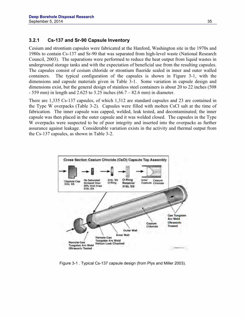
Deep Borehole Disposal Research September 5, 2014 35
3.2.1 Cs-137 and Sr-90 Capsule Inventory Cesium and strontium capsules were fabricated at the Hanford, Washington site in the 1970s and 1980s to contain Cs-137 and Sr-90 that was separated from high-level waste (National Research Council, 2003). The separations were performed to reduce the heat output from liquid wastes in underground storage tanks and with the expectation of beneficial use from the resulting capsules. The capsules consist of cesium chloride or strontium fluoride sealed in inner and outer walled containers. The typical configuration of the capsules is shown in Figure 3-1, with the dimensions and capsule materials given in Table 3-1. Some variation in capsule design and dimensions exist, but the general design of stainless steel containers is about 20 to 22 inches (508 - 559 mm) in length and 2.625 to 3.25 inches (66.7 – 82.6 mm) in diameter.
There are 1,335 Cs-137 capsules, of which 1,312 are standard capsules and 23 are contained in the Type W overpacks (Table 3-2). Capsules were filled with molten CsCl salt at the time of fabrication. The inner capsule was capped, welded, leak tested, and decontaminated; the inner capsule was then placed in the outer capsule and it was welded closed. The capsules in the Type W overpacks were suspected to be of poor integrity and inserted into the overpacks as further assurance against leakage. Considerable variation exists in the activity and thermal output from the Cs-137 capsules, as shown in Table 3-2.
Figure 3-1 . Typical Cs-137 capsule design (from Plys and Miller 2003).
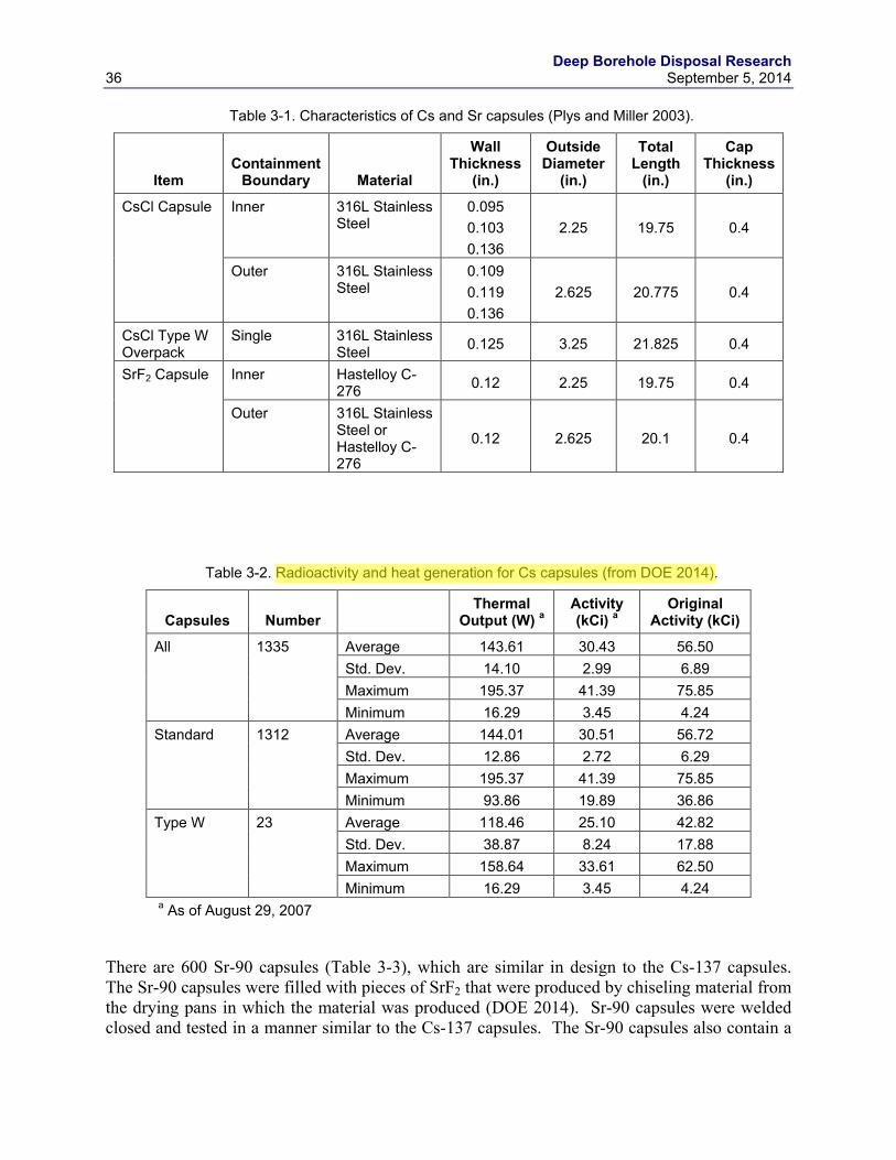
Deep Borehole Disposal Research 36 September 5, 2014
Table 3-1. Characteristics of Cs and Sr capsules (Plys and Miller 2003).
Item Containment
Boundary Material
Wall Thickness
(in.)
Outside Diameter
(in.)
Total Length
(in.)
Cap Thickness
(in.)
CsCl Capsule Inner 316L Stainless Steel
0.095 0.103 0.136
2.25 19.75 0.4
Outer 316L Stainless Steel
0.109 0.119 0.136
2.625 20.775 0.4
CsCl Type W Overpack
Single 316L Stainless Steel 0.125 3.25 21.825 0.4
SrF2 Capsule Inner Hastelloy C-276 0.12 2.25 19.75 0.4
Outer 316L Stainless Steel or Hastelloy C-276
0.12 2.625 20.1 0.4
Table 3-2. Radioactivity and heat generation for Cs capsules (from DOE 2014).
Capsules Number Thermal
Output (W) a Activity (kCi) a
Original Activity (kCi)
All 1335 Average 143.61 30.43 56.50 Std. Dev. 14.10 2.99 6.89 Maximum 195.37 41.39 75.85 Minimum 16.29 3.45 4.24
Standard 1312 Average 144.01 30.51 56.72 Std. Dev. 12.86 2.72 6.29 Maximum 195.37 41.39 75.85 Minimum 93.86 19.89 36.86
Type W 23 Average 118.46 25.10 42.82 Std. Dev. 38.87 8.24 17.88 Maximum 158.64 33.61 62.50 Minimum 16.29 3.45 4.24
a As of August 29, 2007
There are 600 Sr-90 capsules (Table 3-3), which are similar in design to the Cs-137 capsules. The Sr-90 capsules were filled with pieces of SrF2 that were produced by chiseling material from the drying pans in which the material was produced (DOE 2014). Sr-90 capsules were welded closed and tested in a manner similar to the Cs-137 capsules. The Sr-90 capsules also contain a
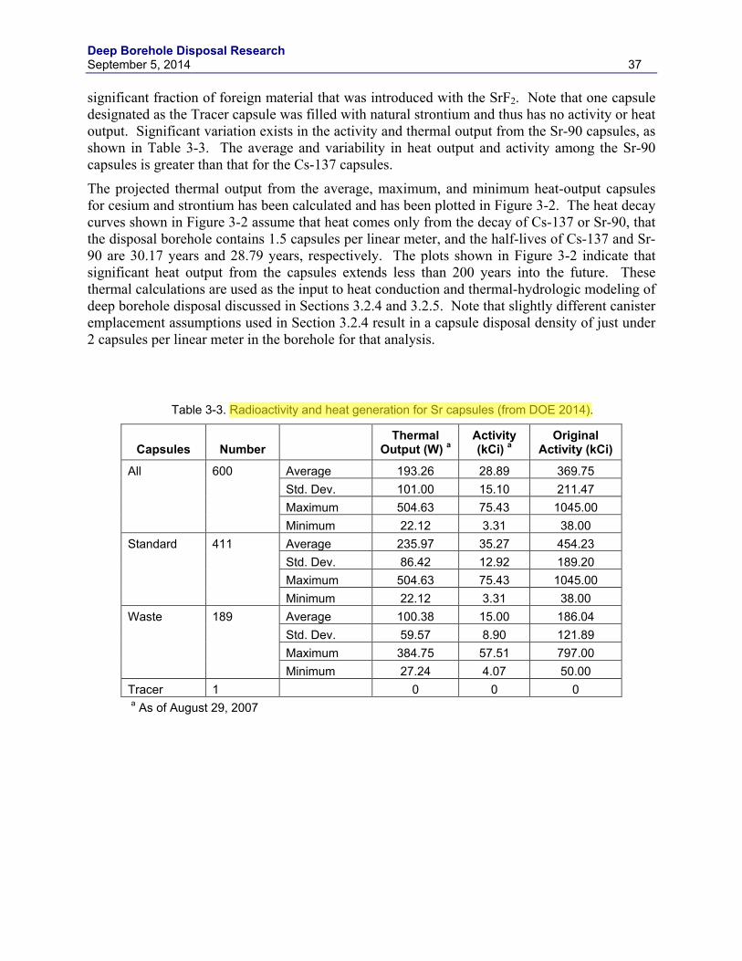
Deep Borehole Disposal Research September 5, 2014 37
significant fraction of foreign material that was introduced with the SrF2. Note that one capsule designated as the Tracer capsule was filled with natural strontium and thus has no activity or heat output. Significant variation exists in the activity and thermal output from the Sr-90 capsules, as shown in Table 3-3. The average and variability in heat output and activity among the Sr-90 capsules is greater than that for the Cs-137 capsules.
The projected thermal output from the average, maximum, and minimum heat-output capsules for cesium and strontium has been calculated and has been plotted in Figure 3-2. The heat decay curves shown in Figure 3-2 assume that heat comes only from the decay of Cs-137 or Sr-90, that the disposal borehole contains 1.5 capsules per linear meter, and the half-lives of Cs-137 and Sr-90 are 30.17 years and 28.79 years, respectively. The plots shown in Figure 3-2 indicate that significant heat output from the capsules extends less than 200 years into the future. These thermal calculations are used as the input to heat conduction and thermal-hydrologic modeling of deep borehole disposal discussed in Sections 3.2.4 and 3.2.5. Note that slightly different canister emplacement assumptions used in Section 3.2.4 result in a capsule disposal density of just under 2 capsules per linear meter in the borehole for that analysis.
Table 3-3. Radioactivity and heat generation for Sr capsules (from DOE 2014).
Capsules Number Thermal
Output (W) a Activity (kCi) a
Original Activity (kCi)
All 600 Average 193.26 28.89 369.75 Std. Dev. 101.00 15.10 211.47 Maximum 504.63 75.43 1045.00 Minimum 22.12 3.31 38.00
Standard 411 Average 235.97 35.27 454.23 Std. Dev. 86.42 12.92 189.20 Maximum 504.63 75.43 1045.00 Minimum 22.12 3.31 38.00
Waste 189 Average 100.38 15.00 186.04 Std. Dev. 59.57 8.90 121.89 Maximum 384.75 57.51 797.00 Minimum 27.24 4.07 50.00
Tracer 1 0 0 0 a As of August 29, 2007
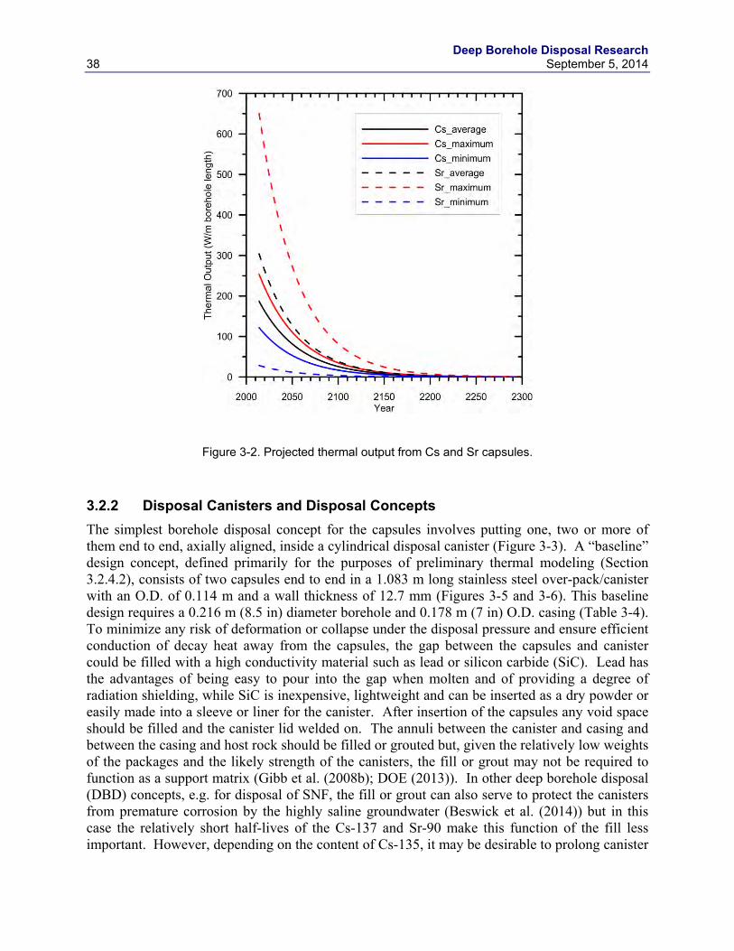
Deep Borehole Disposal Research 38 September 5, 2014
Figure 3-2. Projected thermal output from Cs and Sr capsules.
3.2.2 Disposal Canisters and Disposal Concepts The simplest borehole disposal concept for the capsules involves putting one, two or more of them end to end, axially aligned, inside a cylindrical disposal canister (Figure 3-3). A “baseline” design concept, defined primarily for the purposes of preliminary thermal modeling (Section 3.2.4.2), consists of two capsules end to end in a 1.083 m long stainless steel over-pack/canister with an O.D. of 0.114 m and a wall thickness of 12.7 mm (Figures 3-5 and 3-6). This baseline design requires a 0.216 m (8.5 in) diameter borehole and 0.178 m (7 in) O.D. casing (Table 3-4). To minimize any risk of deformation or collapse under the disposal pressure and ensure efficient conduction of decay heat away from the capsules, the gap between the capsules and canister could be filled with a high conductivity material such as lead or silicon carbide (SiC). Lead has the advantages of being easy to pour into the gap when molten and of providing a degree of radiation shielding, while SiC is inexpensive, lightweight and can be inserted as a dry powder or easily made into a sleeve or liner for the canister. After insertion of the capsules any void space should be filled and the canister lid welded on. The annuli between the canister and casing and between the casing and host rock should be filled or grouted but, given the relatively low weights of the packages and the likely strength of the canisters, the fill or grout may not be required to function as a support matrix (Gibb et al. (2008b); DOE (2013)). In other deep borehole disposal (DBD) concepts, e.g. for disposal of SNF, the fill or grout can also serve to protect the canisters from premature corrosion by the highly saline groundwater (Beswick et al. (2014)) but in this case the relatively short half-lives of the Cs-137 and Sr-90 make this function of the fill less important. However, depending on the content of Cs-135, it may be desirable to prolong canister
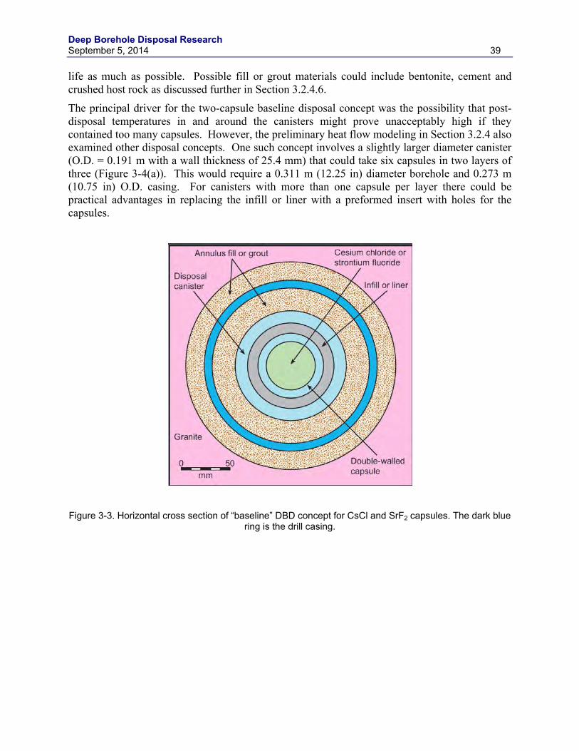
Deep Borehole Disposal Research September 5, 2014 39
life as much as possible. Possible fill or grout materials could include bentonite, cement and crushed host rock as discussed further in Section 3.2.4.6.
The principal driver for the two-capsule baseline disposal concept was the possibility that post-disposal temperatures in and around the canisters might prove unacceptably high if they contained too many capsules. However, the preliminary heat flow modeling in Section 3.2.4 also examined other disposal concepts. One such concept involves a slightly larger diameter canister (O.D. = 0.191 m with a wall thickness of 25.4 mm) that could take six capsules in two layers of three (Figure 3-4(a)). This would require a 0.311 m (12.25 in) diameter borehole and 0.273 m (10.75 in) O.D. casing. For canisters with more than one capsule per layer there could be practical advantages in replacing the infill or liner with a preformed insert with holes for the capsules.
Figure 3-3. Horizontal cross section of “baseline” DBD concept for CsCl and SrF2 capsules. The dark blue
ring is the drill casing.
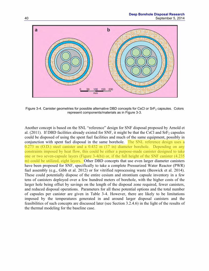
Deep Borehole Disposal Research 40 September 5, 2014
Figure 3-4. Canister geometries for possible alternative DBD concepts for CsCl or SrF2 capsules. Colors
represent components/materials as in Figure 3-3.
Another concept is based on the SNL “reference” design for SNF disposal proposed by Arnold et al. (2011). If DBD facilities already existed for SNF, it might be that the CsCl and SrF2 capsules could be disposed of using the spent fuel facilities and much of the same equipment, possibly in conjunction with spent fuel disposal in the same borehole. The SNL reference design uses a 0.273 m (O.D.) steel canister and a 0.432 m (17 in) diameter borehole. Depending on any constraints imposed by heat flow, this could be either a purpose-made canister designed to take one or two seven-capsule layers (Figure 3-4(b)) or, if the full height of the SNF canister (4.235 m) could be utilized, eight layers. Other DBD concepts that use even larger diameter canisters have been proposed for SNF, specifically to take a complete Pressurized Water Reactor (PWR) fuel assembly (e.g., Gibb et al. 2012) or for vitrified reprocessing waste (Beswick et al. 2014). These could potentially dispose of the entire cesium and strontium capsule inventory in a few tens of canisters deployed over a few hundred meters of borehole, with the higher costs of the larger hole being offset by savings on the length of the disposal zone required, fewer canisters, and reduced disposal operations. Parameters for all these potential options and the total number of capsules per canister are given in Table 3-4. However, there are likely to be limitations imposed by the temperatures generated in and around larger disposal canisters and the feasibilities of such concepts are discussed later (see Section 3.2.4.6) in the light of the results of the thermal modeling for the baseline case.
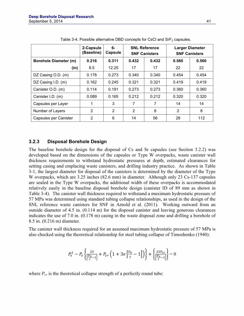
Deep Borehole Disposal Research September 5, 2014 41
Table 3-4. Possible alternative DBD concepts for CsCl and SrF2 capsules.
2-Capsule (Baseline)
6-Capsule
SNL Reference SNF Canisters
Larger Diameter SNF Canisters
Borehole Diameter (m) 0.216 0.311 0.432 0.432 0.560 0.560
(in) 8.5 12.25 17 17 22 22
DZ Casing O.D. (m) 0.178 0.273 0.340 0.340 0.454 0.454
DZ Casing I.D. (m) 0.162 0.245 0.321 0.321 0.419 0.419
Canister O.D. (m) 0.114 0.191 0.273 0.273 0.360 0.360
Canister I.D. (m) 0.089 0.165 0.212 0.212 0.320 0.320
Capsules per Layer 1 3 7 7 14 14
Number of Layers 2 2 2 8 2 8
Capsules per Canister 2 6 14 56 28 112
3.2.3 Disposal Borehole Design The baseline borehole design for the disposal of Cs and Sr capsules (see Section 3.2.2) was developed based on the dimensions of the capsules or Type W overpacks, waste canister wall thickness requirements to withstand hydrostatic pressures at depth, estimated clearances for setting casing and emplacing waste canisters, and drilling industry practice. As shown in Table 3-1, the largest diameter for disposal of the canisters is determined by the diameter of the Type W overpacks, which are 3.25 inches (82.6 mm) in diameter. Although only 23 Cs-137 capsules are sealed in the Type W overpacks, the additional width of these overpacks is accommodated relatively easily in the baseline disposal borehole design (canister ID of 89 mm as shown in Table 3-4). The canister wall thickness required to withstand a maximum hydrostatic pressure of 57 MPa was determined using standard tubing collapse relationships, as used in the design of the SNL reference waste canisters for SNF in Arnold et al. (2011). Working outward from an outside diameter of 4.5 in. (0.114 m) for the disposal canister and leaving generous clearances indicates the use of 7.0 in. (0.178 m) casing in the waste disposal zone and drilling a borehole of 8.5 in. (0.216 m) diameter.
The canister wall thickness required for an assumed maximum hydrostatic pressure of 57 MPa is also checked using the theoretical relationship for steel tubing collapse of Timoshenko (1940):
𝑃𝑒2 − 𝑃𝑒 �2𝑆
�𝐷0𝑡 −1�+ 𝑃𝑐𝑐 �1 + 3𝑒 �𝐷𝑜
𝑡− 1��� + � 2𝑆𝑃𝑐𝑐
�𝐷𝑜𝑡 −1�� = 0
where Pcr is the theoretical collapse strength of a perfectly round tube:
Deep Borehole Disposal Research 42 September 5, 2014
𝑃𝑐𝑐 = �2𝐸
1 − 𝜇2� �1
�𝐷𝑜𝑡− 1�
�
3
and Pe is the collapse pressure with ellipticity (psi), E is Young’s Modulus of the steel, µ is Poisson’s Ratio, Do is the outside diameter, t is the wall thickness, S is the yield strength, and e is the ellipticity. Assuming the outside diameter of 4.5 in. (0.114 m), wall thickness of 0.5 in. for the baseline design, yield strength of 36000 psi, Young’s Modulus of 3×10⁷ psi, Poisson’s Ratio of 0.3, and ellipticity of 0.002 for a machined canister, the theoretical collapse strength is 58.2 MPa (8560 psi).
The resulting baseline disposal borehole design is shown schematically in Figure 3-5. This design is similar to that developed for the reference case documented in Arnold et al. (2011), but with a significantly smaller bottom hole diameter of 8.5 in. A 5,000 m deep borehole with 8.5 in. diameter in crystalline rock is well within drilling experience of the geothermal industry and should be readily achievable under most geological conditions at depth. It is also worthwhile noting that problems related to borehole breakouts and differential horizontal stress would be less extreme and more easily managed in a 8.5 in. diameter borehole than in a 17 in. borehole.
The specifications for the borehole and casing in the baseline design are given in Table 3-5, along with the total cost estimate. Drilling and completion costs are estimated using the SNL estimation tool for geothermal wells and assume rig time for logging and testing of the borehole and the need for directional drilling controls for depths below 1500 ft. The estimated total cost of $17.4 M for the baseline 8.5 in. borehole is less than half of the cost for the 17 in. diameter borehole ($40.9 M) described in Arnold et al. (2011).
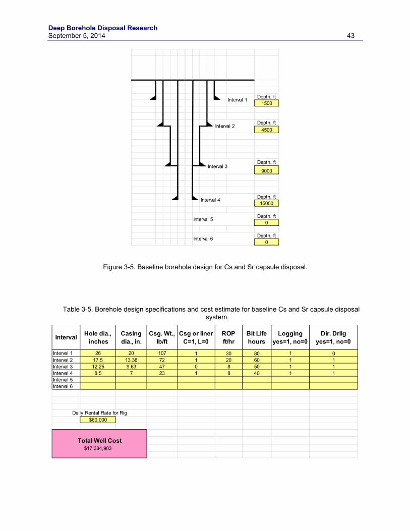
Deep Borehole Disposal Research September 5, 2014 43
Figure 3-5. Baseline borehole design for Cs and Sr capsule disposal.
Table 3-5. Borehole design specifications and cost estimate for baseline Cs and Sr capsule disposal
system.
Depth, ft1500
Depth, ft4500
Depth, ft
9000
Depth, ft15000
Depth, ft0
Depth, ft0
Interval 5
Interval 6
Interval 1
Interval 2
Interval 3
Interval 4
Interval Hole dia., inches
Casingdia., in.
Csg. Wt., lb/ft
Csg or linerC=1, L=0
ROPft/hr
Bit Lifehours
Loggingyes=1, no=0
Dir. Drllgyes=1, no=0
Interval 1 26 20 107 1 30 80 1 0Interval 2 17.5 13.38 72 1 20 60 1 1Interval 3 12.25 9.63 47 0 8 50 1 1Interval 4 8.5 7 23 1 8 40 1 1Interval 5Interval 6
$60,000
$17,384,903
Daily Rental Rate for Rig
Total Well Cost
Deep Borehole Disposal Research 44 September 5, 2014
The final borehole design for any DBD concept can only be generated with a detailed knowledge of the geology and hydrogeology of the area and of the engineering, logistical, economic and other requirements. This is particularly so for factors which affect the size, strength and weight of the casing strings employed and, hence, govern the choice of drill rig. However, by making certain simplifying assumptions examples of borehole designs potentially suitable for disposal concepts, such as those above, can be created to serve as starting points for any modifications necessitated by site-related or other factors.
On the assumption that the geology is primarily granitic rock from the surface to total depth (TD), that it is stable and that no overpressures or large differential horizontal stresses would be encountered, example borehole designs are given in Table 3-6 for each of the potential disposal concepts listed in Table 3-4. For each design a short, large diameter conductor would be drilled to a depth of between 30 and 50 m. The disposal zone (DZ) (3000 – 5000 m) casing is seamless (welded) and perforated to reduce weight, eliminate any wellbore pressure problems and facilitate annulus filling and grouting. Above the DZ this casing should either extend all the way to the surface as a liner or transition smoothly into a “guidance tieback” (Arnold et al. (2011)). A tube with a smooth inside from surface to TD is essential so there are no “upsets” to impede deployment of the waste canisters. Once filling of the DZ with waste canisters is completed that part of the final casing (or the “guidance tieback”) above the DZ, which is un-cemented, could be cut/detached and recovered to facilitate sealing of the borehole. It might prove possible to reuse this recovered portion of the casing.
The cost of drilling a fully cased borehole to 5 km increases exponentially with the diameter at TD. Estimates of the cost of drilling such holes (including site development and supervision) are given in Table 3-7 for diameters from the smallest required for disposal of the Hanford CsCl and SrF2 capsules up to the largest that have been proposed for DBD of vitrified reprocessing waste (Beswick et al. 2014). These estimates are based on the actual costs of drilling the smaller diameter holes in a European context extrapolated to the largest size and serve as a comparison to the estimated costs from the SNL geothermal well estimation tool. Although the costs are cited in US$, it should be noted that current drill rig hire rates tend to be 25 to 35% lower in North America than in Europe so the costs given in Table 3-7 may be conservative for DBD in the USA. For example, the cost of implementing the baseline case (0.216 m hole) in the USA calculated using the Sandia estimation tool, assuming a US daily rental rate for the drill rig of $60,000, gives a total well cost (including logging) of $17.4 M (Table 3-5). These costs are also for “one off” holes and could decrease by up to 50% for subsequent holes (Beswick 2008). However, the latter may not be a relevant consideration for DBD of the Hanford capsules unless their disposal was part of a larger DBD program.
For the baseline concept of two-capsule disposal canisters, the total inventory of 1335 CsCl and 600 SrF2 capsules could be accommodated in 968 canisters occupying about 1,300 m of the DZ in a 0.216 m diameter borehole. If the borehole is drilled to 5 km the main seals could be emplaced just above 4 km depth, providing more than the 3 km of isolation generally regarded as appropriate for DBD (Gibb et al. 2008b 2012; Brady et al. 2009; Beswick et al. 2014) at a cost of around $20 M plus the cost of canisters, packaging, emplacement and sealing. Alternatively, the cost could be significantly reduced by drilling the borehole to only a little over 4 km and still providing the 3 km of isolation for the waste canisters.

Deep Borehole Disposal Research September 5, 2014 45
In the absence of any constraints arising from the temperatures generated in and around the waste canisters, the entire inventory could be fitted into approximately 35 SNL reference SNF canisters 0.273 m in diameter requiring about 165 m of DZ in a 0.432 m diameter borehole.
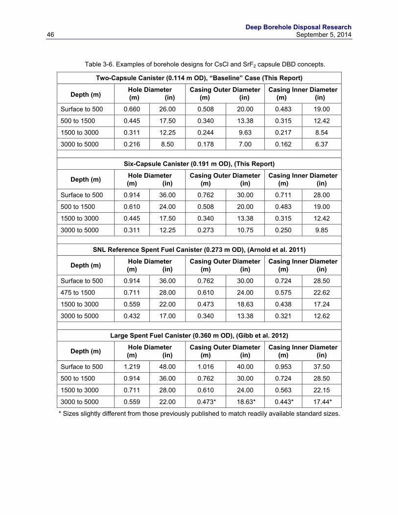
Deep Borehole Disposal Research 46 September 5, 2014
Table 3-6. Examples of borehole designs for CsCl and SrF2 capsule DBD concepts.
Two-Capsule Canister (0.114 m OD), “Baseline” Case (This Report)
Depth (m) Hole Diameter Casing Outer Diameter Casing Inner Diameter (m) (in) (m) (in) (m) (in)
Surface to 500 0.660 26.00 0.508 20.00 0.483 19.00
500 to 1500 0.445 17.50 0.340 13.38 0.315 12.42
1500 to 3000 0.311 12.25 0.244 9.63 0.217 8.54
3000 to 5000 0.216 8.50 0.178 7.00 0.162 6.37
Six-Capsule Canister (0.191 m OD), (This Report)
Depth (m) Hole Diameter Casing Outer Diameter Casing Inner Diameter (m) (in) (m) (in) (m) (in)
Surface to 500 0.914 36.00 0.762 30.00 0.711 28.00
500 to 1500 0.610 24.00 0.508 20.00 0.483 19.00
1500 to 3000 0.445 17.50 0.340 13.38 0.315 12.42
3000 to 5000 0.311 12.25 0.273 10.75 0.250 9.85
SNL Reference Spent Fuel Canister (0.273 m OD), (Arnold et al. 2011)
Depth (m) Hole Diameter Casing Outer Diameter Casing Inner Diameter (m) (in) (m) (in) (m) (in)
Surface to 500 0.914 36.00 0.762 30.00 0.724 28.50
475 to 1500 0.711 28.00 0.610 24.00 0.575 22.62
1500 to 3000 0.559 22.00 0.473 18.63 0.438 17.24
3000 to 5000 0.432 17.00 0.340 13.38 0.321 12.62
Large Spent Fuel Canister (0.360 m OD), (Gibb et al. 2012)
Depth (m) Hole Diameter Casing Outer Diameter Casing Inner Diameter (m) (in) (m) (in) (m) (in)
Surface to 500 1.219 48.00 1.016 40.00 0.953 37.50
500 to 1500 0.914 36.00 0.762 30.00 0.724 28.50
1500 to 3000 0.711 28.00 0.610 24.00 0.563 22.15
3000 to 5000 0.559 22.00 0.473* 18.63* 0.443* 17.44*
* Sizes slightly different from those previously published to match readily available standard sizes.
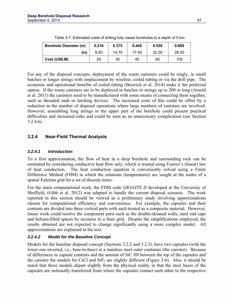
Deep Borehole Disposal Research September 5, 2014 47
Table 3-7. Estimated costs of drilling fully cased boreholes to a depth of 5 km.
Borehole Diameter (m) 0.216 0.375 0.445 0.559 0.660
(in) 8.50 14.75 17.50 22.00 26.00
Cost (US$.M) 20 30 40 60 100
For any of the disposal concepts, deployment of the waste canisters could be singly, in small batches or longer strings with emplacement by wireline, coiled tubing or via the drill pipe. The economic and operational benefits of coiled tubing (Beswick et al. 2014) make it the preferred option. If the waste canisters are to be deployed in batches or strings up to 200 m long (Arnold et al. 2011) the canisters need to be manufactured with some means of connecting them together, such as threaded ends or latching devices. The increased costs of this could be offset by a reduction in the number of disposal operations where large numbers of canisters are involved. However, assembling long strings in the upper part of the borehole could present practical difficulties and increased risks and could be seen as an unnecessary complication (see Section 3.2.4.6).
3.2.4 Near-Field Thermal Analysis 3.2.4.1 Introduction
To a first approximation, the flow of heat in a deep borehole and surrounding rock can be estimated by considering conductive heat flow only, which is treated using Fourier’s (linear) law of heat conduction. The heat conduction equation is conveniently solved using a Finite Difference Method (FDM) in which the solutions (temperatures) are sought at the nodes of a spatial Eulerian grid for a set of discrete times.
For the main computational work, the FDM code GRANITE II developed at the University of Sheffield, (Gibb et al. 2012) was adapted to handle the current disposal scenario. The work reported in this section should be viewed as a preliminary study involving approximations chosen for computational efficiency and convenience. For example, the capsules and their contents are divided into three vertical parts with each treated as a composite material. However, future work could resolve the component parts such as the double-skinned walls, steel end caps and helium-filled spaces by recourse to a finer grid. Despite the simplifications employed, the results obtained are not expected to change significantly using a more complex model. All approximations are explained in the text. 3.2.4.2 Model for the Baseline Concept
Models for the baseline disposal concept (Sections 3.2.2 and 3.2.3), have two capsules (with the lower one inverted, i.e., base-to-base) in a stainless steel outer container (the canister). Because of differences in capsule contents and the amount of SiC fill between the top of the capsules and the canister the models for CsCl and SrF2 are slightly different (Figure 3-6). Also, it should be noted that these models depart slightly from the physical reality in that the steel bases of the capsules are notionally transferred from where the capsules contact each other to the respective
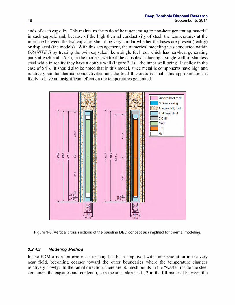
Deep Borehole Disposal Research 48 September 5, 2014
ends of each capsule. This maintains the ratio of heat generating to non-heat generating material in each capsule and, because of the high thermal conductivity of steel, the temperatures at the interface between the two capsules should be very similar whether the bases are present (reality) or displaced (the models). With this arrangement, the numerical modeling was conducted within GRANITE II by treating the twin capsules like a single fuel rod, which has non-heat generating parts at each end. Also, in the models, we treat the capsules as having a single wall of stainless steel while in reality they have a double wall (Figure 3-1) – the inner wall being Hastelloy in the case of SrF2. It should also be noted that in this model, since metallic components have high and relatively similar thermal conductivities and the total thickness is small, this approximation is likely to have an insignificant effect on the temperatures generated.
Figure 3-6. Vertical cross sections of the baseline DBD concept as simplified for thermal modeling.
3.2.4.3 Modeling Method
In the FDM a non-uniform mesh spacing has been employed with finer resolution in the very near field, becoming coarser toward the outer boundaries where the temperature changes relatively slowly. In the radial direction, there are 30 mesh points in the “waste” inside the steel container (the capsules and contents), 2 in the steel skin itself, 2 in the fill material between the
Deep Borehole Disposal Research September 5, 2014 49
canister and casing, 2 within the casing, another 1 in the fill material between the casing and the rock and, finally, 36 out in the host rock. In the vertical direction, there are 30 mesh points in the central, heat generating region. The numbers of mesh points used in the lower and upper non-heat generating sections were scaled proportionally to the lengths of these sections, with at least 5 points in all cases. The top, middle and lower sections of the canister contents (Figure 3-7) are each treated as if they were single materials with their thermophysical properties calculated as weighted composites.
Figure 3-7. Schematic diagram showing the components of each section of the canister contents for CsCl
and SrF2 disposal canisters (not to scale).
For each of the middle, heat generating sections, the radiogenic heat is distributed evenly over the cylindrical volumes depicted in Figure 3-7, which include the steel capsule walls and SiC infill or sleeve. Densities (ρ) and specific heats (c) of all the composite materials (sections) are obtained using well-known mixing rules based on volume fractions (ϕi) and mass fractions (γi) respectively:
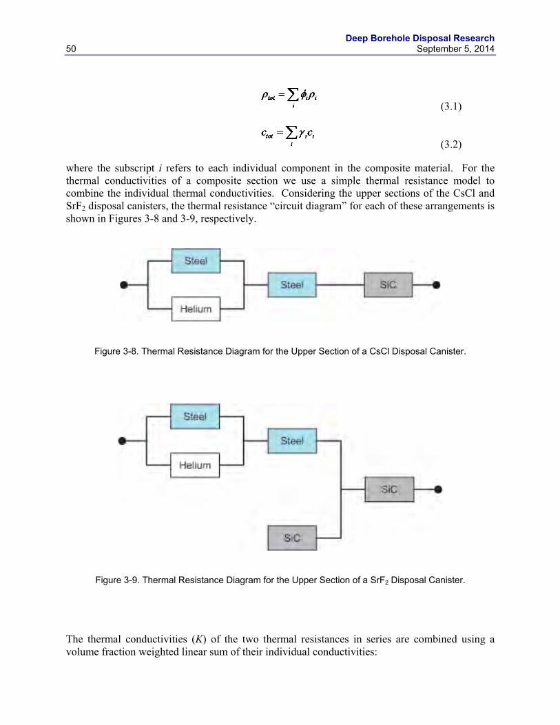
Deep Borehole Disposal Research 50 September 5, 2014
(3.1)
(3.2)
where the subscript i refers to each individual component in the composite material. For the thermal conductivities of a composite section we use a simple thermal resistance model to combine the individual thermal conductivities. Considering the upper sections of the CsCl and SrF2 disposal canisters, the thermal resistance “circuit diagram” for each of these arrangements is shown in Figures 3-8 and 3-9, respectively.
Figure 3-8. Thermal Resistance Diagram for the Upper Section of a CsCl Disposal Canister.
Figure 3-9. Thermal Resistance Diagram for the Upper Section of a SrF2 Disposal Canister.
The thermal conductivities (K) of the two thermal resistances in series are combined using a volume fraction weighted linear sum of their individual conductivities:
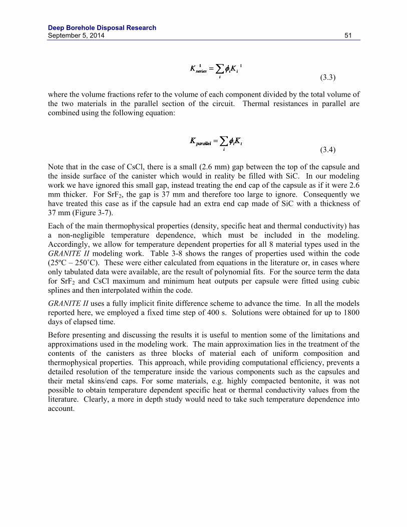
Deep Borehole Disposal Research September 5, 2014 51
(3.3)
where the volume fractions refer to the volume of each component divided by the total volume of the two materials in the parallel section of the circuit. Thermal resistances in parallel are combined using the following equation:
(3.4)
Note that in the case of CsCl, there is a small (2.6 mm) gap between the top of the capsule and the inside surface of the canister which would in reality be filled with SiC. In our modeling work we have ignored this small gap, instead treating the end cap of the capsule as if it were 2.6 mm thicker. For SrF2, the gap is 37 mm and therefore too large to ignore. Consequently we have treated this case as if the capsule had an extra end cap made of SiC with a thickness of 37 mm (Figure 3-7).
Each of the main thermophysical properties (density, specific heat and thermal conductivity) has a non-negligible temperature dependence, which must be included in the modeling. Accordingly, we allow for temperature dependent properties for all 8 material types used in the GRANITE II modeling work. Table 3-8 shows the ranges of properties used within the code (25ºC – 250˚C). These were either calculated from equations in the literature or, in cases where only tabulated data were available, are the result of polynomial fits. For the source term the data for SrF2 and CsCl maximum and minimum heat outputs per capsule were fitted using cubic splines and then interpolated within the code.
GRANITE II uses a fully implicit finite difference scheme to advance the time. In all the models reported here, we employed a fixed time step of 400 s. Solutions were obtained for up to 1800 days of elapsed time.
Before presenting and discussing the results it is useful to mention some of the limitations and approximations used in the modeling work. The main approximation lies in the treatment of the contents of the canisters as three blocks of material each of uniform composition and thermophysical properties. This approach, while providing computational efficiency, prevents a detailed resolution of the temperature inside the various components such as the capsules and their metal skins/end caps. For some materials, e.g. highly compacted bentonite, it was not possible to obtain temperature dependent specific heat or thermal conductivity values from the literature. Clearly, a more in depth study would need to take such temperature dependence into account.
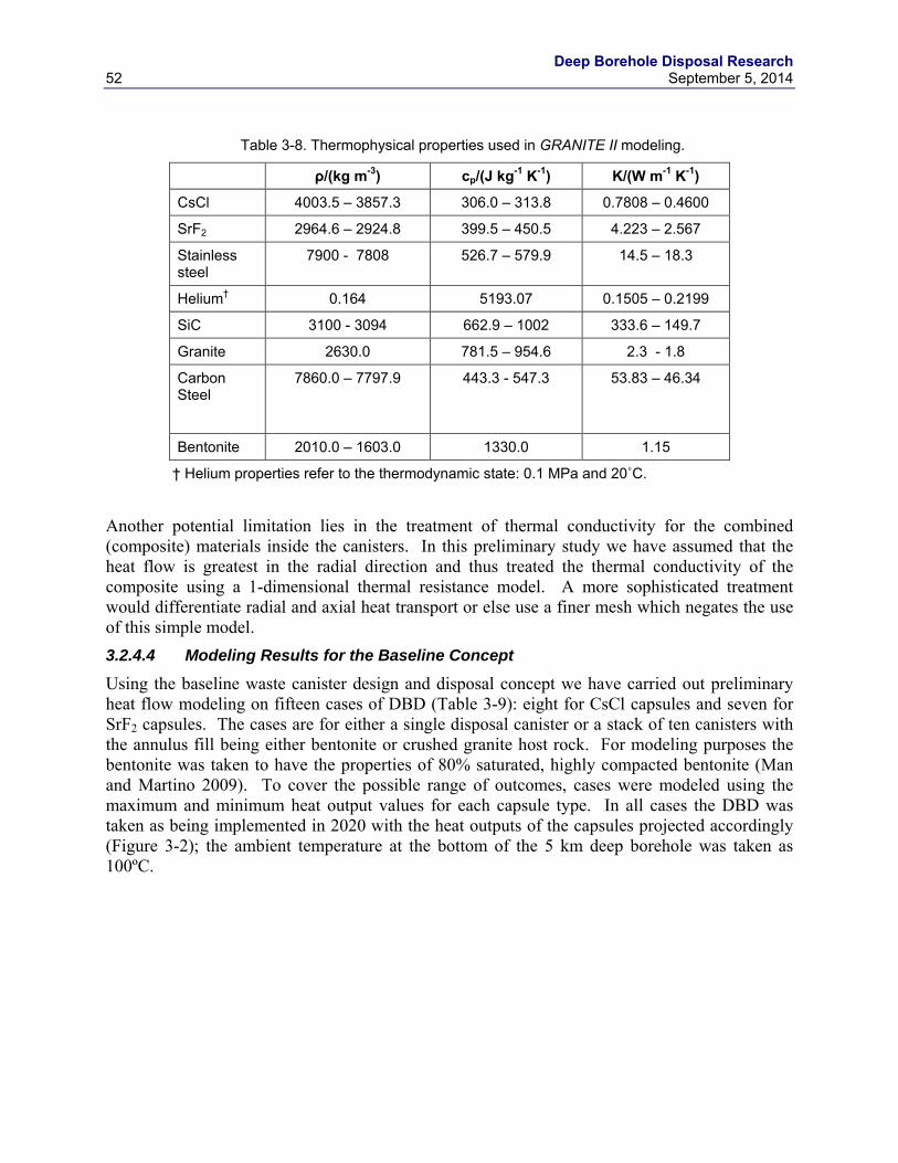
Deep Borehole Disposal Research 52 September 5, 2014
Table 3-8. Thermophysical properties used in GRANITE II modeling.
ρ/(kg m-3) cp/(J kg-1 K-1) K/(W m-1 K-1)
CsCl 4003.5 – 3857.3 306.0 – 313.8 0.7808 – 0.4600
SrF2 2964.6 – 2924.8 399.5 – 450.5 4.223 – 2.567
Stainless steel
7900 - 7808 526.7 – 579.9 14.5 – 18.3
Helium† 0.164 5193.07 0.1505 – 0.2199
SiC 3100 - 3094 662.9 – 1002 333.6 – 149.7
Granite 2630.0 781.5 – 954.6 2.3 - 1.8
Carbon Steel
7860.0 – 7797.9 443.3 - 547.3 53.83 – 46.34
Bentonite 2010.0 – 1603.0 1330.0 1.15
† Helium properties refer to the thermodynamic state: 0.1 MPa and 20˚C.
Another potential limitation lies in the treatment of thermal conductivity for the combined (composite) materials inside the canisters. In this preliminary study we have assumed that the heat flow is greatest in the radial direction and thus treated the thermal conductivity of the composite using a 1-dimensional thermal resistance model. A more sophisticated treatment would differentiate radial and axial heat transport or else use a finer mesh which negates the use of this simple model. 3.2.4.4 Modeling Results for the Baseline Concept
Using the baseline waste canister design and disposal concept we have carried out preliminary heat flow modeling on fifteen cases of DBD (Table 3-9): eight for CsCl capsules and seven for SrF2 capsules. The cases are for either a single disposal canister or a stack of ten canisters with the annulus fill being either bentonite or crushed granite host rock. For modeling purposes the bentonite was taken to have the properties of 80% saturated, highly compacted bentonite (Man and Martino 2009). To cover the possible range of outcomes, cases were modeled using the maximum and minimum heat output values for each capsule type. In all cases the DBD was taken as being implemented in 2020 with the heat outputs of the capsules projected accordingly (Figure 3-2); the ambient temperature at the bottom of the 5 km deep borehole was taken as 100ºC.
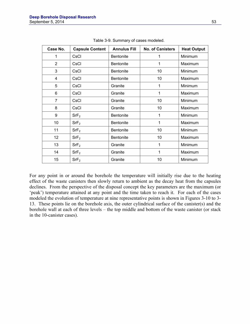
Deep Borehole Disposal Research September 5, 2014 53
Table 3-9. Summary of cases modeled.
Case No. Capsule Content Annulus Fill No. of Canisters Heat Output
1 CsCl Bentonite 1 Minimum
2 CsCl Bentonite 1 Maximum
3 CsCl Bentonite 10 Minimum
4 CsCl Bentonite 10 Maximum
5 CsCl Granite 1 Minimum
6 CsCl Granite 1 Maximum
7 CsCl Granite 10 Minimum
8 CsCl Granite 10 Maximum
9 SrF2 Bentonite 1 Minimum
10 SrF2 Bentonite 1 Maximum
11 SrF2 Bentonite 10 Minimum
12 SrF2 Bentonite 10 Maximum
13 SrF2 Granite 1 Minimum
14 SrF2 Granite 1 Maximum
15 SrF2 Granite 10 Minimum
For any point in or around the borehole the temperature will initially rise due to the heating effect of the waste canisters then slowly return to ambient as the decay heat from the capsules declines. From the perspective of the disposal concept the key parameters are the maximum (or ‘peak’) temperature attained at any point and the time taken to reach it. For each of the cases modeled the evolution of temperature at nine representative points is shown in Figures 3-10 to 3-13. These points lie on the borehole axis, the outer cylindrical surface of the canister(s) and the borehole wall at each of three levels – the top middle and bottom of the waste canister (or stack in the 10-canister cases).
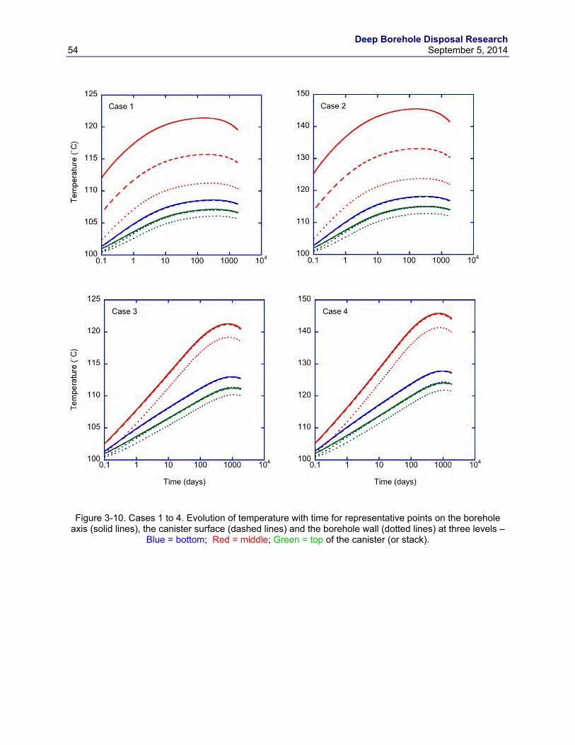
Deep Borehole Disposal Research 54 September 5, 2014
Figure 3-10. Cases 1 to 4. Evolution of temperature with time for representative points on the borehole axis (solid lines), the canister surface (dashed lines) and the borehole wall (dotted lines) at three levels –
Blue = bottom; Red = middle; Green = top of the canister (or stack).
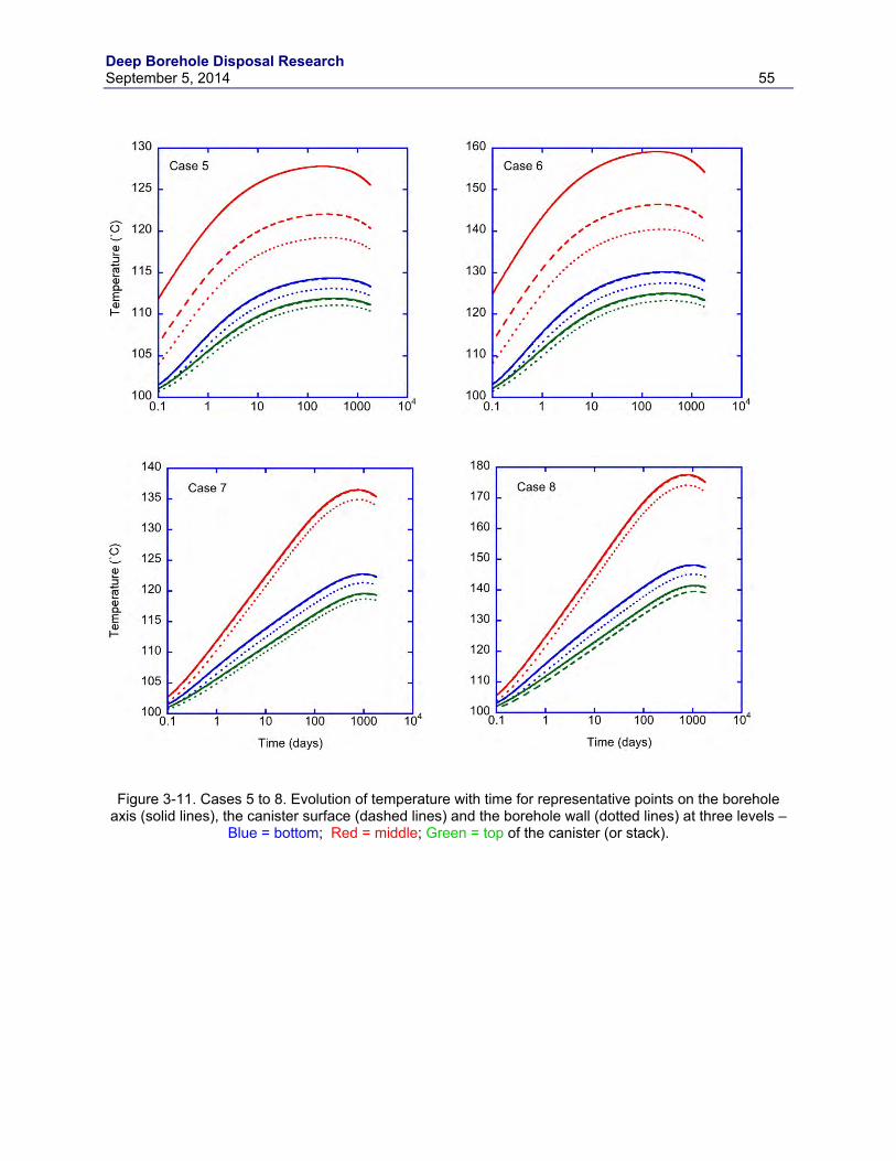
Deep Borehole Disposal Research September 5, 2014 55
Figure 3-11. Cases 5 to 8. Evolution of temperature with time for representative points on the borehole axis (solid lines), the canister surface (dashed lines) and the borehole wall (dotted lines) at three levels –
Blue = bottom; Red = middle; Green = top of the canister (or stack).
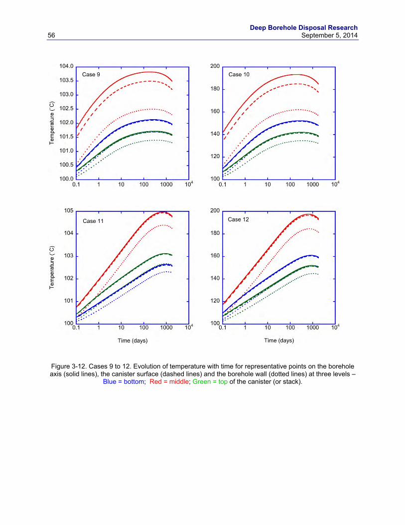
Deep Borehole Disposal Research 56 September 5, 2014
Figure 3-12. Cases 9 to 12. Evolution of temperature with time for representative points on the borehole axis (solid lines), the canister surface (dashed lines) and the borehole wall (dotted lines) at three levels –
Blue = bottom; Red = middle; Green = top of the canister (or stack).
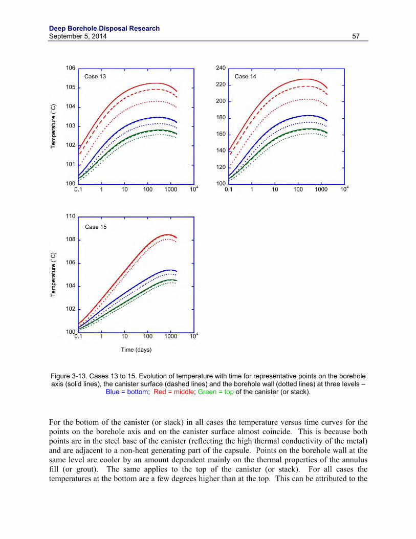
Deep Borehole Disposal Research September 5, 2014 57
Figure 3-13. Cases 13 to 15. Evolution of temperature with time for representative points on the borehole axis (solid lines), the canister surface (dashed lines) and the borehole wall (dotted lines) at three levels –
Blue = bottom; Red = middle; Green = top of the canister (or stack).
For the bottom of the canister (or stack) in all cases the temperature versus time curves for the points on the borehole axis and on the canister surface almost coincide. This is because both points are in the steel base of the canister (reflecting the high thermal conductivity of the metal) and are adjacent to a non-heat generating part of the capsule. Points on the borehole wall at the same level are cooler by an amount dependent mainly on the thermal properties of the annulus fill (or grout). The same applies to the top of the canister (or stack). For all cases the temperatures at the bottom are a few degrees higher than at the top. This can be attributed to the
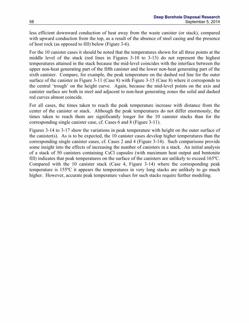
Deep Borehole Disposal Research 58 September 5, 2014
less efficient downward conduction of heat away from the waste canister (or stack), compared with upward conduction from the top, as a result of the absence of steel casing and the presence of host rock (as opposed to fill) below (Figure 3-6).
For the 10 canister cases it should be noted that the temperatures shown for all three points at the middle level of the stack (red lines in Figures 3-10 to 3-13) do not represent the highest temperatures attained in the stack because the mid-level coincides with the interface between the upper non-heat generating part of the fifth canister and the lower non-heat generating part of the sixth canister. Compare, for example, the peak temperature on the dashed red line for the outer surface of the canister in Figure 3-11 (Case 8) with Figure 3-15 (Case 8) where it corresponds to the central ‘trough’ on the height curve. Again, because the mid-level points on the axis and canister surface are both in steel and adjacent to non-heat generating zones the solid and dashed red curves almost coincide.
For all cases, the times taken to reach the peak temperature increase with distance from the center of the canister or stack. Although the peak temperatures do not differ enormously, the times taken to reach them are significantly longer for the 10 canister stacks than for the corresponding single canister case, cf. Cases 6 and 8 (Figure 3-11).
Figures 3-14 to 3-17 show the variations in peak temperature with height on the outer surface of the canister(s). As is to be expected, the 10 canister cases develop higher temperatures than the corresponding single canister cases, cf. Cases 2 and 4 (Figure 3-14). Such comparisons provide some insight into the effects of increasing the number of canisters in a stack. An initial analysis of a stack of 50 canisters containing CsCl capsules (with maximum heat output and bentonite fill) indicates that peak temperatures on the surface of the canisters are unlikely to exceed 165ºC. Compared with the 10 canister stack (Case 4, Figure 3-14) where the corresponding peak temperature is 155ºC it appears the temperatures in very long stacks are unlikely to go much higher. However, accurate peak temperature values for such stacks require further modeling.
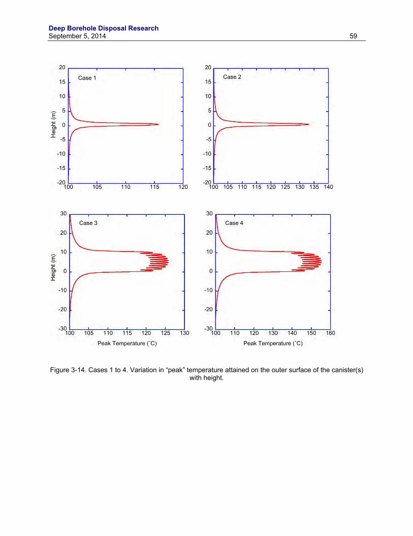
Deep Borehole Disposal Research September 5, 2014 59
Figure 3-14. Cases 1 to 4. Variation in “peak” temperature attained on the outer surface of the canister(s)
with height.
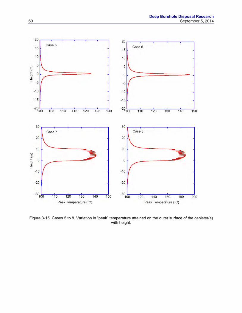
Deep Borehole Disposal Research 60 September 5, 2014
Figure 3-15. Cases 5 to 8. Variation in “peak” temperature attained on the outer surface of the canister(s)
with height.
Deep Borehole Disposal Research September 5, 2014 61
Figure 3-16. Cases 9 to 12. Variation in “peak” temperature attained on the outer surface of the canister(s) with height.
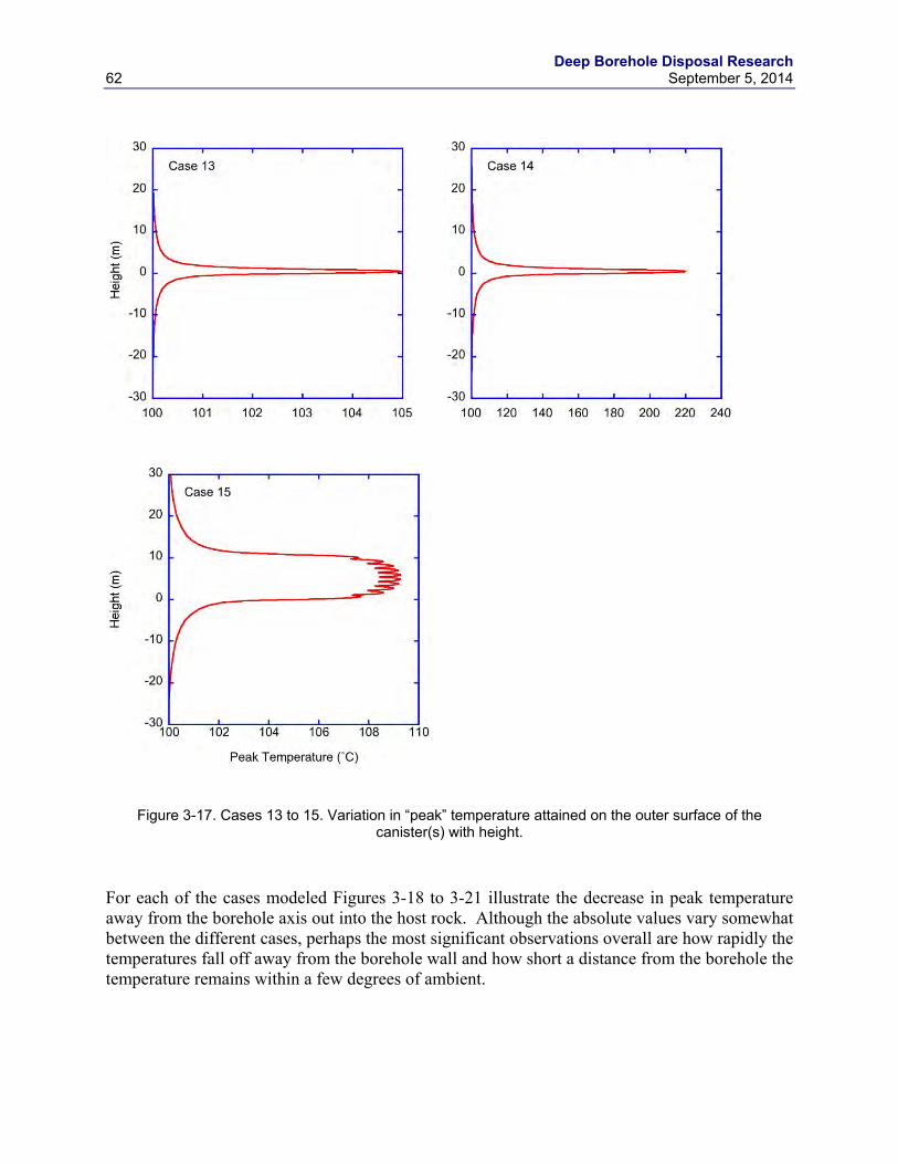
Deep Borehole Disposal Research 62 September 5, 2014
Figure 3-17. Cases 13 to 15. Variation in “peak” temperature attained on the outer surface of the canister(s) with height.
For each of the cases modeled Figures 3-18 to 3-21 illustrate the decrease in peak temperature away from the borehole axis out into the host rock. Although the absolute values vary somewhat between the different cases, perhaps the most significant observations overall are how rapidly the temperatures fall off away from the borehole wall and how short a distance from the borehole the temperature remains within a few degrees of ambient.
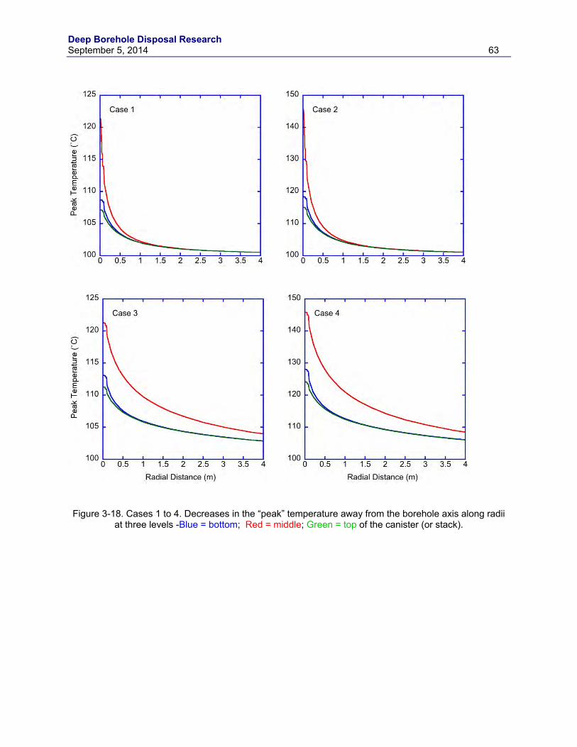
Deep Borehole Disposal Research September 5, 2014 63
Figure 3-18. Cases 1 to 4. Decreases in the “peak” temperature away from the borehole axis along radii
at three levels -Blue = bottom; Red = middle; Green = top of the canister (or stack).
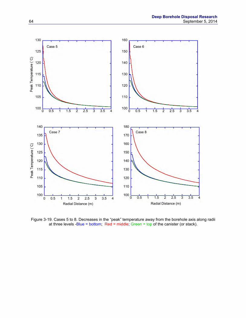
Deep Borehole Disposal Research 64 September 5, 2014
Figure 3-19. Cases 5 to 8. Decreases in the “peak” temperature away from the borehole axis along radii
at three levels -Blue = bottom; Red = middle; Green = top of the canister (or stack).
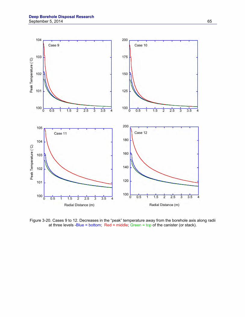
Deep Borehole Disposal Research September 5, 2014 65
Figure 3-20. Cases 9 to 12. Decreases in the “peak” temperature away from the borehole axis along radii
at three levels -Blue = bottom; Red = middle; Green = top of the canister (or stack).
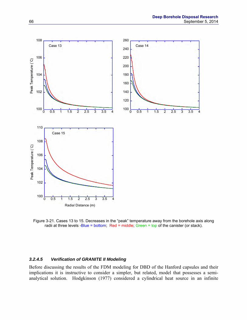
Deep Borehole Disposal Research 66 September 5, 2014
Figure 3-21. Cases 13 to 15. Decreases in the “peak” temperature away from the borehole axis along radii at three levels -Blue = bottom; Red = middle; Green = top of the canister (or stack).
3.2.4.5 Verification of GRANITE II Modeling
Before discussing the results of the FDM modeling for DBD of the Hanford capsules and their implications it is instructive to consider a simpler, but related, model that possesses a semi-analytical solution. Hodgkinson (1977) considered a cylindrical heat source in an infinite
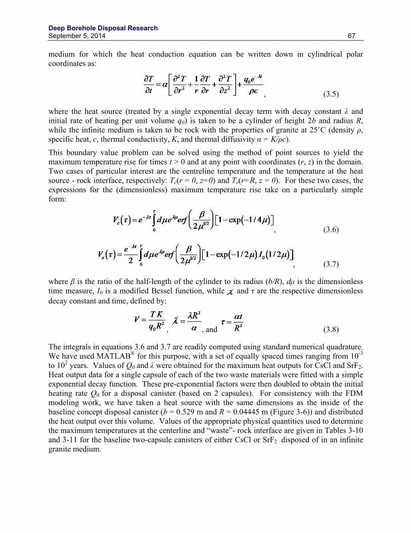
Deep Borehole Disposal Research September 5, 2014 67
medium for which the heat conduction equation can be written down in cylindrical polar coordinates as:
, (3.5)
where the heat source (treated by a single exponential decay term with decay constant λ and initial rate of heating per unit volume q0) is taken to be a cylinder of height 2b and radius R, while the infinite medium is taken to be rock with the properties of granite at 25˚C (density ρ, specific heat, c, thermal conductivity, K, and thermal diffusivity α = K/ρc).
This boundary value problem can be solved using the method of point sources to yield the maximum temperature rise for times t > 0 and at any point with coordinates (r, z) in the domain. Two cases of particular interest are the centreline temperature and the temperature at the heat source - rock interface, respectively: Tc(r = 0, z=0) and Te(r=R, z = 0). For these two cases, the expressions for the (dimensionless) maximum temperature rise take on a particularly simple form:
, (3.6)
, (3.7)
where β is the ratio of the half-length of the cylinder to its radius (b/R), dμ is the dimensionless time measure, I0 is a modified Bessel function, while and τ are the respective dimensionless decay constant and time, defined by:
, , and (3.8)
The integrals in equations 3.6 and 3.7 are readily computed using standard numerical quadrature. We have used MATLAB® for this purpose, with a set of equally spaced times ranging from 10-3 to 102 years. Values of Q0 and λ were obtained for the maximum heat outputs for CsCl and SrF2. Heat output data for a single capsule of each of the two waste materials were fitted with a simple exponential decay function. These pre-exponential factors were then doubled to obtain the initial heating rate Q0 for a disposal canister (based on 2 capsules). For consistency with the FDM modeling work, we have taken a heat source with the same dimensions as the inside of the baseline concept disposal canister (b = 0.529 m and R = 0.04445 m (Figure 3-6)) and distributed the heat output over this volume. Values of the appropriate physical quantities used to determine the maximum temperatures at the centerline and “waste”- rock interface are given in Tables 3-10 and 3-11 for the baseline two-capsule canisters of either CsCl or SrF2 disposed of in an infinite granite medium.
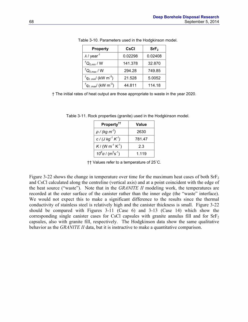
Deep Borehole Disposal Research 68 September 5, 2014
Table 3-10. Parameters used in the Hodgkinson model.
Property CsCl SrF2
λ / year-1 0.02298 0.02408 †Q0,min / W 141.378 32.870 †Q0,max / W 294.28 749.85 †q0 ,min/ (kW m-3) 21.528 5.0052 †q0 ,max/ (kW m-3) 44.811 114.18
† The initial rates of heat output are those appropriate to waste in the year 2020.
Table 3-11. Rock properties (granite) used in the Hodgkinson model.
Property†† Value
ρ / (kg m-3) 2630
c / (J kg-1 K-1) 781.47
K / (W m-1 K-1) 2.3
106α / (m2s-1) 1.119
†† Values refer to a temperature of 25˚C.
Figure 3-22 shows the change in temperature over time for the maximum heat cases of both SrF2 and CsCl calculated along the centreline (vertical axis) and at a point coincident with the edge of the heat source (“waste”). Note that in the GRANITE II modeling work, the temperatures are recorded at the outer surface of the canister rather than the inner edge (the “waste” interface). We would not expect this to make a significant difference to the results since the thermal conductivity of stainless steel is relatively high and the canister thickness is small. Figure 3-22 should be compared with Figures 3-11 (Case 6) and 3-13 (Case 14) which show the corresponding single canister cases for CsCl capsules with granite annulus fill and for SrF2 capsules, also with granite fill, respectively. The Hodgkinson data show the same qualitative behavior as the GRANITE II data, but it is instructive to make a quantitative comparison.
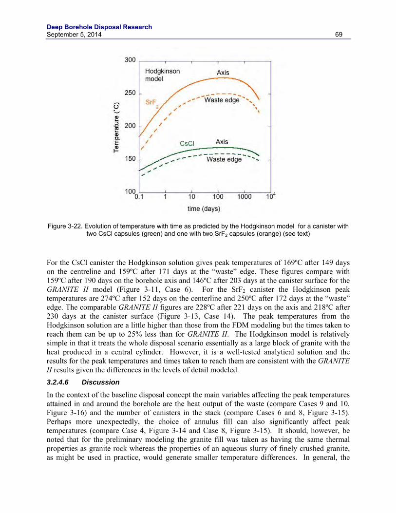
Deep Borehole Disposal Research September 5, 2014 69
Figure 3-22. Evolution of temperature with time as predicted by the Hodgkinson model for a canister with
two CsCl capsules (green) and one with two SrF2 capsules (orange) (see text)
For the CsCl canister the Hodgkinson solution gives peak temperatures of 169ºC after 149 days on the centreline and 159ºC after 171 days at the “waste” edge. These figures compare with 159ºC after 190 days on the borehole axis and 146ºC after 203 days at the canister surface for the GRANITE II model (Figure 3-11, Case 6). For the SrF2 canister the Hodgkinson peak temperatures are 274ºC after 152 days on the centerline and 250ºC after 172 days at the “waste” edge. The comparable GRANITE II figures are 228ºC after 221 days on the axis and 218ºC after 230 days at the canister surface (Figure 3-13, Case 14). The peak temperatures from the Hodgkinson solution are a little higher than those from the FDM modeling but the times taken to reach them can be up to 25% less than for GRANITE II. The Hodgkinson model is relatively simple in that it treats the whole disposal scenario essentially as a large block of granite with the heat produced in a central cylinder. However, it is a well-tested analytical solution and the results for the peak temperatures and times taken to reach them are consistent with the GRANITE II results given the differences in the levels of detail modeled. 3.2.4.6 Discussion
In the context of the baseline disposal concept the main variables affecting the peak temperatures attained in and around the borehole are the heat output of the waste (compare Cases 9 and 10, Figure 3-16) and the number of canisters in the stack (compare Cases 6 and 8, Figure 3-15). Perhaps more unexpectedly, the choice of annulus fill can also significantly affect peak temperatures (compare Case 4, Figure 3-14 and Case 8, Figure 3-15). It should, however, be noted that for the preliminary modeling the granite fill was taken as having the same thermal properties as granite rock whereas the properties of an aqueous slurry of finely crushed granite, as might be used in practice, would generate smaller temperature differences. In general, the
Deep Borehole Disposal Research 70 September 5, 2014
rises in temperature at the canister surfaces are relatively small (< 50ºC) except for the SrF2 canisters with the maximum heat output and for the CsCl combinations of ten canisters with maximum heat output.
From the standpoint of the safety case the only limits on temperatures in DBD, short of those required for the host granite to begin melting (around 700ºC (Attrill and Gibb 2003)), are those imposed by the capsules themselves and the materials used as fill. For the capsules CsCl melts at 645ºC and SrF2 at 1477ºC but the main constraint is likely to be the temperatures at which corrosive reactions between the salt and the metal capsule become significant. A previous study for long-term dry storage of the Hanford capsules (Heard et al. 2003) identified maximum temperatures for the salt-metal interface of 317ºC and 540ºC for the CsCl and SrF2 respectively. While any detrimental effects of such temperatures may not be critical in a borehole disposal scenario, especially inside another canister (overpack), these would seem to provide appropriately conservative upper limits for the temperatures on the inner surface of the capsules. Given the high thermal conductivities of the capsules, canisters and any fill or liner (SiC or lead) and the proximity of the outer surface of the canister to the capsule inner wall in the disposal concept, the temperatures at the former predicted by our modeling results (Figures 3-14 to 3-17) should be very good approximations to those at the latter. In none of the cases modeled does the peak temperature at the canister surface come close to these limits for the salt-metal interface.
The modeling of the 10 canister cases assumes all 10 canisters are emplaced at the bottom of the borehole simultaneously, which would be the case if they were deployed as a string. Given the need for such strings to be assembled remotely (within a shielded facility) at the well-head it seems unlikely that this could be achieved in less than a day and would probably require longer. Under these circumstances, where a canister is not to be lowered down the borehole almost immediately, the initial rise in the surface temperature of the canister once it is immersed in the wellbore fluid could be significant. Of particular potential concern would be cases where the rise is large enough to initiate local boiling of the fluid. Assuming an ambient well-head temperature up to 25ºC a rise in canister surface temperature approaching 75ºC could cause problems. Among the multi-canister cases modeled, only Cases 8 and 12 generate surface temperatures greater than this but in some of these (e.g., Case 14) a rise of 75ºC is achieved within the first 20 days, suggesting such canisters may only be suitable for DBD if deployed singly or lowered down the borehole without appreciable delay. In reality this would result in their being emplaced at around 6 - 8 hour intervals if deployed by coiled tubing (Beswick et al. 2014).
If the annulus fill is required to function either as a physical support for the canisters or as a barrier to premature corrosion of the canisters by groundwater (or both) there may be limits to the temperatures to which it can be subjected. It is widely accepted that bentonite comprised mainly of Na-montmorillonite cannot be used as a barrier in radioactive waste disposal applications where temperatures may exceed ~ 100ºC, although a case has been made for raising this limit slightly (Wersin et al., 2007). Notwithstanding any practical problems in getting it down 4 or 5 km in a water-filled borehole in its highly compacted form, it is evident from the modeling results that bentonite is unlikely to be a suitable annulus fill material unless its sole function is to fill the space. Crushed granite host rock is subject to no real temperature limits and can provide physical support for the waste canisters but does not prevent groundwater access to the canisters. The same is true of silica sand. Cement grouts are widely used in the drilling industry and can function as sealing and support matrices (SSM) in DBD (Beswick et al. 2014). There are no well-defined temperature limits for such grouts, but a research program at the
Deep Borehole Disposal Research September 5, 2014 71
University of Sheffield (funded by the UK Engineering & Physical Sciences Research Council) suggests a formulation suitable for DBD application can be developed to withstand temperatures approaching 200ºC. In some of the SrF2 DBD cases modeled the temperatures in the annulus around canisters with the maximum heat output approach or exceed 200ºC (e.g., Cases 12 and 14). If an annulus fill with a sealing and support function is required for such cases a Pb-alloy SSM (Gibb et al., 2008b) could be employed, albeit at a cost. As suggested above (Section 3.2.2), it is unlikely that DBD of the Hanford capsules would require the annulus fill to support the canisters but the need for sealing (protection) could depend on the Cs-135 content of the capsules and the requirements of the long-term safety case.
It is known from heat flow modeling for the DBD of consolidated spent fuel rods (e.g., Gibb et al., 2012) that the rises in temperature in and around the waste canisters increase almost linearly with the number of fuel rods in the disposal canister. Doubling the number of rods results in just over double the temperature rise and it is reasonable to assume that a similar relationship would hold when the number of CsCl or SrF2 capsules in the canister is increased, as in the alternative DBD concepts illustrated in Figure 3-4. Extrapolating on this basis from the baseline concept modeling to the 6-capsule (two layers of three) concept (Figure 3-4(a)), a 3-fold increase of the temperature rises at the salt-metal interfaces would still leave them well below the conservative limits of 317ºC (Cs) and 540ºC (Sr). Further extrapolation to the 14-capsule (two layers of seven) concept (Figure 3-4(b)) would take the salt-metal interface temperatures above the limits in some cases, notably where maximum heat outputs are used for all the capsules in the canister. However, this is an unlikely scenario in practice as the filling of the waste canisters in these alternative concepts can be managed to ensure each delivers close to the average heat output for the capsules. In this way the salt-metal interface temperatures could probably be kept within the conservative limits even for the larger canister (Figure 3-4(b)). Notwithstanding any potential economic or practical benefits of alternative concepts, before any further consideration is given to options larger than the 6-capsule concept heat flow modeling with different individual capsule heat outputs is necessary. In conclusion, the near-field thermal modeling indicates that (1) there are no problems that would prevent DBD of the Hanford capsules arising from their heat outputs and (2) an initial preference for the smallest practical disposal canister (overpack/canister) and borehole diameters may be unwarranted if there are economic or practical advantages in alternative DBD concepts.
3.2.5 Thermal-Hydrologic Analyses Heat from radioactive waste in the deep borehole disposal system may impact groundwater flow via thermal-hydrological processes through direct thermal expansion of fluids and by free convection (Arnold et al. 2011b). Thermal-hydrologic simulations for the deep borehole disposal of SNF have been used to model the transport of radionuclides in several versions of performance assessment calculations (Swift et al. 2011, Lee et al. 2112, and DOE 2013). This section documents similar thermal-hydrologic modeling for the disposal of the Cs-137 and Sr-90 capsules in a single disposal borehole.
Although the initial heat output from the entire inventory of Cs-137 and Sr-90 capsules is significantly higher than for a borehole containing PWR SNF from the reference deep borehole disposal design (Arnold et al. 2011a), the cumulative heat output from the capsules is only about 11% of the cumulative heat from spent fuel disposal over the first 1,000 years following
Deep Borehole Disposal Research 72 September 5, 2014
disposal. Consequently, the total amount of heat deposited in the subsurface from deep borehole disposal of the Cs-137 and Sr-90 capsules is much less than heat from SNF disposal over long time scales. This suggests that initial fluid flow from thermal expansion may be greater for disposal of Cs-137 and Sr-90 capsules, and later flow by thermal free convection would be less compared to disposal of SNF (in a single borehole).
The thermal-hydrologic model used in these analyses has a three-dimensional domain consisting of granite overlain by 1,500 m of stratified sedimentary cover. The grid and exterior boundary conditions are the same as those documented in Arnold and Hadgu (2013) and DOE (2013), including an ambient geothermal gradient of 25°C/km. The Cs-137 and Sr-90 capsules are emplaced in the lower 1,300 m of the 5,000 m disposal borehole and it is assumed that emplacement occurs in 2020. The weighted average thermal output for the capsules is uniformly applied within the borehole as an internal boundary condition, with the decay histories shown in Figure 3-2.
Simulated temperatures at a depth of 4,000 m are shown as a function of time following waste emplacement in Figure 3-23. The dashed curve shows the borehole centerline temperature, with a maximum temperature increase of almost 50º C occurring within 10 years of waste emplacement. The solid curve shows the same results for a distance of 1 m from the borehole centerline. It should be noted that the thermal-hydrologic model has a much coarser grid resolution near the borehole than the thermal conduction model described in Section 3.2.4, so the values of simulated temperature are approximate. Recall that the primary objective of the thermal-hydrologic model is to simulate the large-scale fluid circulation resulting from heat-generating waste. Nonetheless, there is general agreement between the thermal-hydrologic model and the detailed thermal conduction model regarding the peak temperature increase and timing.
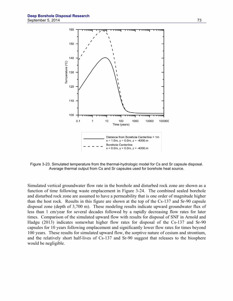
Deep Borehole Disposal Research September 5, 2014 73
Figure 3-23. Simulated temperature from the thermal-hydrologic model for Cs and Sr capsule disposal. Average thermal output from Cs and Sr capsules used for borehole heat source.
Simulated vertical groundwater flow rate in the borehole and disturbed rock zone are shown as a function of time following waste emplacement in Figure 3-24. The combined sealed borehole and disturbed rock zone are assumed to have a permeability that is one order of magnitude higher than the host rock. Results in this figure are shown at the top of the Cs-137 and Sr-90 capsule disposal zone (depth of 3,700 m). These modeling results indicate upward groundwater flux of less than 1 cm/year for several decades followed by a rapidly decreasing flow rates for later times. Comparison of the simulated upward flow with results for disposal of SNF in Arnold and Hadgu (2013) indicates somewhat higher flow rates for disposal of the Cs-137 and Sr-90 capsules for 10 years following emplacement and significantly lower flow rates for times beyond 100 years. These results for simulated upward flow, the sorptive nature of cesium and strontium, and the relatively short half-lives of Cs-137 and Sr-90 suggest that releases to the biosphere would be negligible.
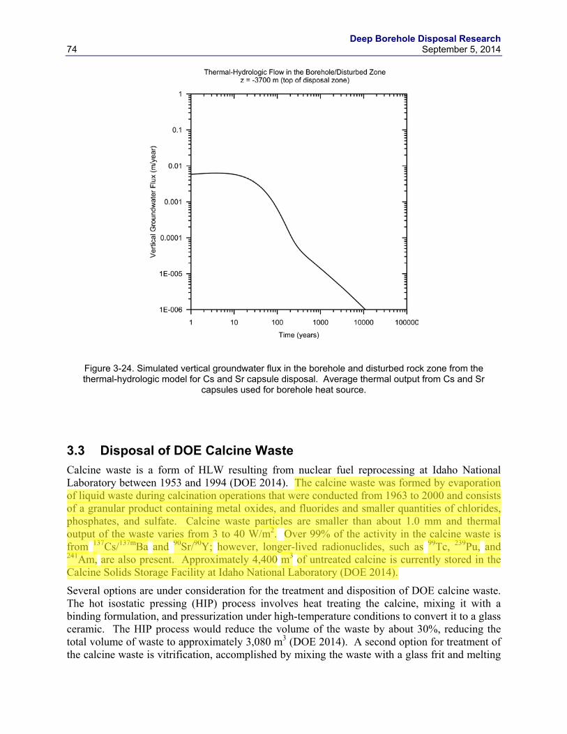
Deep Borehole Disposal Research 74 September 5, 2014
Figure 3-24. Simulated vertical groundwater flux in the borehole and disturbed rock zone from the thermal-hydrologic model for Cs and Sr capsule disposal. Average thermal output from Cs and Sr
capsules used for borehole heat source.
3.3 Disposal of DOE Calcine Waste Calcine waste is a form of HLW resulting from nuclear fuel reprocessing at Idaho National Laboratory between 1953 and 1994 (DOE 2014). The calcine waste was formed by evaporation of liquid waste during calcination operations that were conducted from 1963 to 2000 and consists of a granular product containing metal oxides, and fluorides and smaller quantities of chlorides, phosphates, and sulfate. Calcine waste particles are smaller than about 1.0 mm and thermal output of the waste varies from 3 to 40 W/m2. Over 99% of the activity in the calcine waste is from 137Cs/137mBa and 90Sr/90Y; however, longer-lived radionuclides, such as 99Tc, 239Pu, and 241Am, are also present. Approximately 4,400 m3 of untreated calcine is currently stored in the Calcine Solids Storage Facility at Idaho National Laboratory (DOE 2014).
Several options are under consideration for the treatment and disposition of DOE calcine waste. The hot isostatic pressing (HIP) process involves heat treating the calcine, mixing it with a binding formulation, and pressurization under high-temperature conditions to convert it to a glass ceramic. The HIP process would reduce the volume of the waste by about 30%, reducing the total volume of waste to approximately 3,080 m3 (DOE 2014). A second option for treatment of the calcine waste is vitrification, accomplished by mixing the waste with a glass frit and melting
Deep Borehole Disposal Research September 5, 2014 75
the mixture. The total volume of vitrified calcine waste created by the vitrification option would be about 10,100 m3. The final option is direct disposal of the untreated granular calcine waste. Although the direct disposal option does not afford the advantages of a stabilized waste form, it would involve lower worker radiation exposure, less secondary radioactive waste, and lower costs than the HIP or vitrification options (DOE 2014). Given the greater isolation provided by the geological system in deep borehole disposal relative to shallower mined disposal, direct disposal of the untreated calcine waste would likely obviate the need for additional calcine waste treatment.
Direct disposal of untreated calcine waste is analyzed using the SNL reference design for deep borehole disposal described in Arnold et al. (2011). Disposal in the low-temperature canister design is assumed, given the relatively low thermal output from the calcine waste. Each low-temperature disposal canister has an internal volume of about 0.149 m3. Disposal of all 4,400 m3 of untreated calcine would thus require about 29,550 waste canisters, assuming 100% filling. The reference design for borehole disposal includes 400 disposal canister, so the total number of disposal boreholes would be 74 boreholes. If the canisters could only be filled to 90% of capacity, then about 82 disposal boreholes would be required. Alternatively, if the HIP process could be used to treat the calcine and the reference design canisters were filled to 90% capacity with the treated waste, about 58 disposal boreholes would be required.
A possible alternative for borehole disposal of calcine waste would be in larger-diameter boreholes that are not as deep as the reference design for deep borehole disposal. As described earlier, the bulk of the activity in the calcine waste is from relatively short-lived radionuclides, with considerably smaller contributions from other fission products and actinides (DOE 2014). Boreholes with diameters of up to about 30 inches (0.76 m) have been drilled to depths of 3,000 m (Beswick 2008). It is possible that disposal depths of 1,000 m to 3,000 m would provide adequate isolation for the calcine waste in a borehole disposal system. Long-term performance of this alternative, with disposal of calcine in shallower holes at depths of perhaps 3,000 m or less, remains to be evaluated. However, analyses of disposal of transuranic wastes in very large diameter (3 m) boreholes at significantly shallower depths (bottom-hole depth of 36 m) have demonstrated safety for the particular environmental conditions of the Greater Confinement Disposal system at the Nevada Test Site (Cochran et al. 2001).
3.4 Degradation of Waste Canister Materials, Waste Forms and Drill Casing Materials
The components of the engineered barrier (from waste form to borehole casing/liner) are shown as concentric circles in Figure 3-3. From the inside outwards, the disposal system design must consider degradation of waste form (including capsules and contents), waste canister material, borehole casing/liner materials (including conductor, surface, final and waste string casing) and cementing between the drill casing and host rock.
3.4.1 Degradation of Waste Canister Materials Before evaluating the degradation of the waste form (CsCl, SrF2, and capsule materials), it is important to understand the chemical and thermal environment life-cycle for the capsules, from filling and storage in a pool, to periodic inspection and future emplacement in a borehole.
Deep Borehole Disposal Research 76 September 5, 2014
3.4.1.1 High-Level Waste Material
A total of approximately 86 MCi of Cs-137 in the form of CsCl was encapsulated by October 1983 and approximately 37 MCi of Sr-90 in the form of SrF2 was encapsulated by January 1985 at the Hanford Waste Encapsulation and Storage Facility (WESF) (Covey 2012). Cs-137 undergoes beta decay with a half-life of 30.17 years forming barium-137m, which emits gamma photons (2.55 minute half-life) to form stable barium-137. Sr-90 undergoes beta decay with a half-life of 28.8 years to form yttium-90, which then undergoes beta decay (64 hour half-life) and emission of an anti-neutrino to form stable zirconium-90. Decay-corrected to 2011, the total remaining activities of Cs and Sr are 38 MCi and 16 MCi, respectively (Covey, 2012).
Loading of CsCl capsules was performed by pouring melted salt. The melting point of pure CsCl is 645°C, and two different types of furnaces were used to melt the material – an induction furnace at a temperature of 730 to 750°C and later a tilt-pour furnace (DOE 1990). On initial loading, the surface of the capsule was subjected to molten salt temperatures (<750°C), but surfaces quickly cooled as CsCl solidified. The presence of impurities in CsCl depresses its melting point. A review of total impurities for selected capsules (Tingey et al. 1983) shows that impurities may account for between 18-31 weight%, including significant chloride salts of aluminum, barium, iron, potassium, sodium and silicon (DOE, 1990). Additionally, CsCl undergoes a phase-change at 469°C which results in a 15% decrease in density on cooling in addition to the 9% change that occurs on solidification below the melting point (DNFSB 1996). Such changes in density led to a void volume in the poured salt. The actual temperatures experienced by the inner 316L stainless steel capsule during and after pouring CsCl could vary greatly depending upon the operator and the location of the inner capsule (DOE 1990). After cooling and welding, inner capsules were cleaned with demineralized water and the surfaces were electopolished (DOE 1990).
Processing temperatures (for example during vacuum tests) for CsCl capsules at the salt-metal interface were expected to not exceed 450°C (Heard et al., 2003) for periods of a few hours to a few days. Similarly, for SrF2 capsules, processing temperatures at the salt-metal interface were not expected to exceed 540°C. SrF2 melts at a much higher temperature (1477°C), so it is unlikely that any phase changes have occurred in the SrF2 capsules. It is important to note that SrF2 capsules also contain additional foreign materials beyond the simple salt, including metallic parts, ceramics and carbonaceous materials taken from floor and hot-cell deck operations (Bryan, Olander and Tingey 2003), which complicate a full understanding of each SrF2 capsule. Since SrF2 was not melted immediately prior to loading, the highest temperatures observed by the inner Hastelloy alloy C-276 capsules (and 316L outer capsules) result from the decay heat only. 3.4.1.2 Capsule Surface and Centerline Temperatures
To understand the temperatures experienced by the waste form (and the subsequent capsule degradation mechanisms), a first approximation of capsule centerline and surface temperature histories have been calculated for both air-cooled and pool-cooled environments.
The decay heat on 1/1/1995 and 1/1/2010 were provided in a presentation to the Nuclear Waste Technical Review Board (Randklev 1994) for both Cs and Sr capsules, as well as the surface and centerline temperatures of the capsules. The same temperature data appears in Final Environmental Impact Statement (DOE 1987).
Deep Borehole Disposal Research September 5, 2014 77
The actual starting point in the transient temperature calculation (in time) is not critical, since the values are scaled according to the exponential decay of the waste heat in the Cs and Sr capsules. The surface and centerline temperatures given in DOE (1987) and Randklev (1994) were assumed to be design values. However, it was also assumed that the cooling air or water inlet temperatures and flow rates were adjusted to achieve these design temperatures given the decay heat as of January 1st, 1995. Assuming the cooling system input temperatures and flow rates were held constant, the heat transfer coefficients would also remain constant, and calculated results could be checked against the tabular values given for January 1st, 2010 and also calculated for different decay heat values at later times.
The thermal analysis for a preliminary design concept for a dry storage facility, which was prepared in 2003 (Heard et al. 2003), provided a basis for the decay heat of the capsules, scaling the capsule decay heat with the half-life of Cs capsules. Power decay from the initial power level is based on the following equation, where P0 is the initial power and ∆t is the number of years to the calorimetric date:
𝑃 = 𝑃0𝑒𝑒𝑒 �−0.6931 ∆𝑡
𝑡1 2⁄�
The approach was to back-calculate equivalent universal heat transfer coefficients in air and water from the temperature results for 1995. An approximate steady state forced convection heat transfer situation was assumed with:
𝑄 = 𝑈 ∗ 𝐴 ∗ �𝑇𝑠𝑠𝑐𝑠𝑠𝑐𝑒 − 𝑇𝑠𝑎𝑎𝑎𝑒𝑎𝑡�
Therefore,
𝑈 ∗ 𝐴 = 𝑄 �𝑇𝑠𝑠𝑐𝑠𝑠𝑐𝑒 − 𝑇𝑠𝑎𝑎𝑎𝑒𝑎𝑡�⁄
where Q = decay heat in W, and U * A is the universal heat transfer coefficient (in air or water) multiplied by capsule surface area in (final units are W/°C). Then, assuming U * A is held constant,
𝑇𝑠𝑠𝑐𝑠𝑠𝑐𝑒 = 𝑇𝑠𝑎𝑎𝑎𝑒𝑎𝑡 + 𝑈 ∗ 𝐴 𝑄⁄
Radiation heat transfer was neglected, based on the assumption that a capsule would be located within a hot enclosure or hot array of capsules, so the radiation heat sink would have a similar temperature to the source. A forced convection environment was assumed where cool ambient air at 22°C (site average ambient air temperature from Heard et al. 2003) or 50°C for water (DOE 1990) is supplied to remove the heat, rather than relying on natural buoyant convection where the heat transfer coefficient would be a function of temperature difference. The Cs and Sr capsules have almost identical geometry, so the U * A function for both capsules should be approximately the same in each media, shown in Table 3-12.
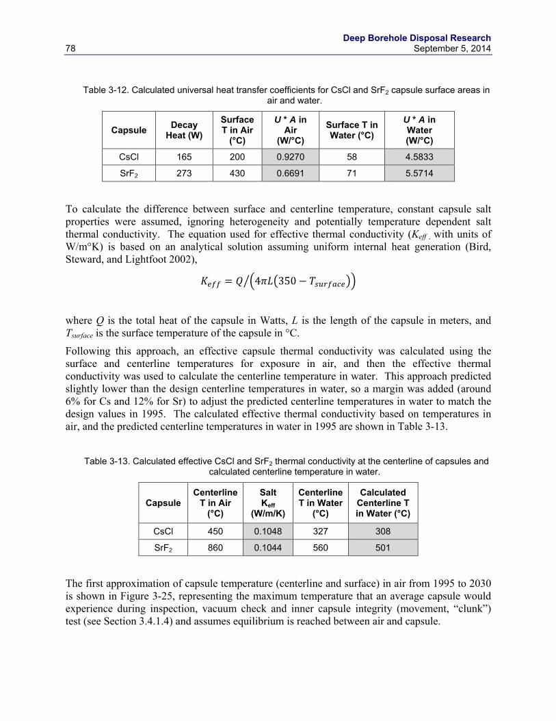
Deep Borehole Disposal Research 78 September 5, 2014
Table 3-12. Calculated universal heat transfer coefficients for CsCl and SrF2 capsule surface areas in
air and water.
Capsule Decay Heat (W)
Surface T in Air
(°C)
U * A in Air
(W/°C) Surface T in Water (°C)
U * A in Water (W/°C)
CsCl 165 200 0.9270 58 4.5833
SrF2 273 430 0.6691 71 5.5714
To calculate the difference between surface and centerline temperature, constant capsule salt properties were assumed, ignoring heterogeneity and potentially temperature dependent salt thermal conductivity. The equation used for effective thermal conductivity (Keff , with units of W/m°K) is based on an analytical solution assuming uniform internal heat generation (Bird, Steward, and Lightfoot 2002),
𝐾𝑒𝑠𝑠 = 𝑄 �4𝜋𝜋�350 − 𝑇𝑠𝑠𝑐𝑠𝑠𝑐𝑒���
where Q is the total heat of the capsule in Watts, L is the length of the capsule in meters, and Tsurface is the surface temperature of the capsule in °C.
Following this approach, an effective capsule thermal conductivity was calculated using the surface and centerline temperatures for exposure in air, and then the effective thermal conductivity was used to calculate the centerline temperature in water. This approach predicted slightly lower than the design centerline temperatures in water, so a margin was added (around 6% for Cs and 12% for Sr) to adjust the predicted centerline temperatures in water to match the design values in 1995. The calculated effective thermal conductivity based on temperatures in air, and the predicted centerline temperatures in water in 1995 are shown in Table 3-13.
Table 3-13. Calculated effective CsCl and SrF2 thermal conductivity at the centerline of capsules and
calculated centerline temperature in water.
Capsule Centerline
T in Air (°C)
Salt Keff
(W/m/K)
Centerline T in Water
(°C)
Calculated Centerline T in Water (°C)
CsCl 450 0.1048 327 308
SrF2 860 0.1044 560 501
The first approximation of capsule temperature (centerline and surface) in air from 1995 to 2030 is shown in Figure 3-25, representing the maximum temperature that an average capsule would experience during inspection, vacuum check and inner capsule integrity (movement, “clunk”) test (see Section 3.4.1.4) and assumes equilibrium is reached between air and capsule.
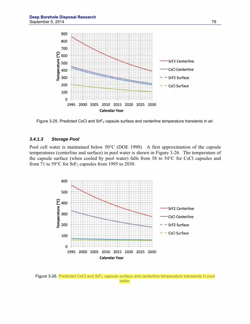
Deep Borehole Disposal Research September 5, 2014 79
Figure 3-25. Predicted CsCl and SrF2 capsule surface and centerline temperature transients in air.
3.4.1.3 Storage Pool
Pool cell water is maintained below 50°C (DOE 1990). A first approximation of the capsule temperatures (centerline and surface) in pool water is shown in Figure 3-26. The temperature of the capsule surface (when cooled by pool water) falls from 58 to 54°C for CsCl capsules and from 71 to 59°C for SrF2 capsules from 1995 to 2030.
Figure 3-26. Predicted CsCl and SrF2 capsule surface and centerline temperature transients in pool water.
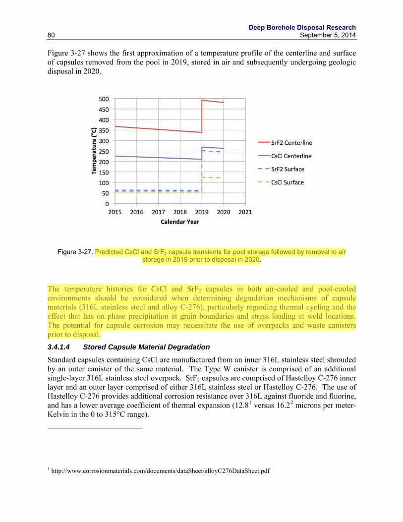
Deep Borehole Disposal Research 80 September 5, 2014
Figure 3-27 shows the first approximation of a temperature profile of the centerline and surface of capsules removed from the pool in 2019, stored in air and subsequently undergoing geologic disposal in 2020.
Figure 3-27. Predicted CsCl and SrF2 capsule transients for pool storage followed by removal to air storage in 2019 prior to disposal in 2020.
The temperature histories for CsCl and SrF2 capsules in both air-cooled and pool-cooled environments should be considered when determining degradation mechanisms of capsule materials (316L stainless steel and alloy C-276), particularly regarding thermal cycling and the effect that has on phase precipitation at grain boundaries and stress loading at weld locations. The potential for capsule corrosion may necessitate the use of overpacks and waste canisters prior to disposal. 3.4.1.4 Stored Capsule Material Degradation
Standard capsules containing CsCl are manufactured from an inner 316L stainless steel shrouded by an outer canister of the same material. The Type W canister is comprised of an additional single-layer 316L stainless steel overpack. SrF2 capsules are comprised of Hastelloy C-276 inner layer and an outer layer comprised of either 316L stainless steel or Hastelloy C-276. The use of Hastelloy C-276 provides additional corrosion resistance over 316L against fluoride and fluorine, and has a lower average coefficient of thermal expansion (12.81 versus 16.22 microns per meter-Kelvin in the 0 to 315°C range).
1 http://www.corrosionmaterials.com/documents/dataSheet/alloyC276DataSheet.pdf
Deep Borehole Disposal Research September 5, 2014 81
The elemental composition of the two canister materials is given in Table 3-14 (SAE, 1986).
Table 3-14. Elemental composition of 316L stainless steel and alloy C-276.
Composition wt%
C Fe Mn Mo Cr Ni Co P S Si W
316L 0.030 Bal (69)
2.00 2.00 to 3.00
16.00 to 18.00
10.00 to 14.00
- 0.045 0.030 1.00 -
C-276 0.02 4.0 to 7.0
1.0 15.0 to 17.0
14.5 to 16.5
Bal (57)
2.5 0.030 0.03 0.08 3.0 to 4.5
In austenitic stainless steels and nickel-based alloys such as SS-316L and C-276 where chromium is added to enhance corrosion resistance, chromium carbides (mainly Cr23C6) can precipitate at the grain boundary at temperatures between 425°C and 815°C. This leads to depletion of the passivating chromium metal in both the grain boundary and the grain body, a process known as sensitization, leading to areas with no passivity, which in-turn corrode preferentially. The capsule materials are then susceptible to inter-granular corrosion (IGC) as a result of elevated carbon content in the steel and sensitizing heat treatments (exposures). As discussed above, the temperature of CsCl-containing SS-316L capsules reached a maximum of 750°C during melt-pouring. During vacuum testing, surface temperatures of SS-316L capsules containing CsCl were lower than the region of concern for IGC, with surface temperatures in air at or below 200°C from 1995 onwards and surface temperatures in water substantially lower. For C-276 capsules containing SrF2, surface temperatures of 430°C were experienced on loading and during periodic inspection, leading to thermal cycling in the lower range of temperatures known to cause IGC.
Semi-annual inner capsule movement (“clunk”) tests are performed on stored capsules, in which the integrity of the inner capsule is evaluated by shaking the capsule to move it while inside the outer capsule. If the inner capsule is swollen, it is assumed there will be no free movement within the outer capsule and no “clunk” will be heard. While most capsules are in good condition, 23 capsules required overpacks (NAS 2003; DOE 2002) potentially because of failing the “clunk” test. Capsule failure may occur because of poor welds and phase-changes as a function of temperature (NAS 2003; DNFSB 1996). A letter report by DNFSB (1995) further states that some capsules have experienced extreme thermal cycling. Such temperatures may include those that cause phase transition in both CsCl and 316L stainless steel.
The chemistry of the cooling pool is controlled using a deionizing system to remove impurities such as corrosion products, dissolved salts, chloride ions, and solid debris. This helps to
2 http://www.atlassteels.com.au/documents/Atlas316-316L.pdf
Deep Borehole Disposal Research 82 September 5, 2014
maintain the pool cell water quality and minimize the potential for external corrosion of the capsules. For 316L, this results in a negligible rate of pitting corrosion. (Covey 2012). However, since the capsules were welded, there is the potential for stress corrosion cracking (SCC) to occur. DNFSB (1996) noted that some CsCl capsules stored in the pool may have experienced chloride-induced SCC near the outer capsule welds due to lack of water chemistry requirements and control. For the 23 capsules requiring overpacks, the 316L SS overpack has a corrosion allowance of 0.318 cm to protect against potential capsule leaks (Fluor, 2003). Overpack temperatures were predicted to be in the range of 200-225°C during normal operations. 316L SS (both capsule and overpack) is susceptible to SSC if exposed to water without proper purity control, particularly when capsules were leased to other facilities as irradiation sources (DNFSB 1996). One capsule has suffered a through-wall crack, while another leak was attributed to a fabrication defect in the weld (DNFSB,1996). 3.4.1.5 Waste Form Degradation in Boreholes
A deep borehole disposal design should include evaluation and selection of borehole casing and/or liners that are resistant to concentrated brines and capable of handling tensile stresses necessary for 4-5 km boreholes, and disposal canisters that are resistant to reducing potentials. The combination of these layered “barrier” materials around the waste capsules, and in conjunction with grouting, should help to mitigate the degradation of the waste form in the borehole.
The peak temperatures at the canister wall are expected to be 145°C for a stack of 10 Cs-137 canisters each containing 2 capsules at a depth of 4 km using a bentonite backfill and disposal occurring in 2020. With a crushed granite backfill, the temperature is expected to peak at 185°C. Peak temperatures for Sr-90 capsules could be as high as 195°C with bentonite backfill. Water circulation is assumed to be very limited.
Conditions downhole for the Cs-137 and Sr-90 capsules are expected to be anoxic with elevated temperatures and brine concentrations. Under these conditions, the 316L and C-276 capsules will most likely be at risk from chloride-induced SCC. If the disposal canister and capsule walls are breached, the CsCl and SrF2 salts will be available to concentrated brines for subsequent dissolution. The room temperature solubility of CsCl is very high at 1910 g/l (Haynes, 2014), while that of SrF2 is relatively low at 0.21 g/l. Simulated SrF2 from the WESF has a low solubility at room temperature (0.135 g/l), increasing slightly with temperature to 0.157g/l at 50°C (Fullam 1976), but the dissolution rate of SrF2 from WESF was dependent on surface area, impurity content, thermal history and temperature (amongst other factors). Given the saturated nature of the brine and its stagnant nature, it is feasible that these soluble salt waste forms may exhibit slower dissolution kinetics.
3.4.2 Disposal Canister Materials At the elevated downhole temperatures, concentrated brines will dominate the water chemistry. Leached sodium and chloride concentrations increase with temperature and depth (Anderson 2004). For boreholes in granite, the pH is expected to be between 7 and 9), the redox potential between -200 and -300 mV (Rebak 2006) and the major brine constituents may include 20 molal calcium, 100 molal chloride and 60 molal sodium (Anderson 2004).
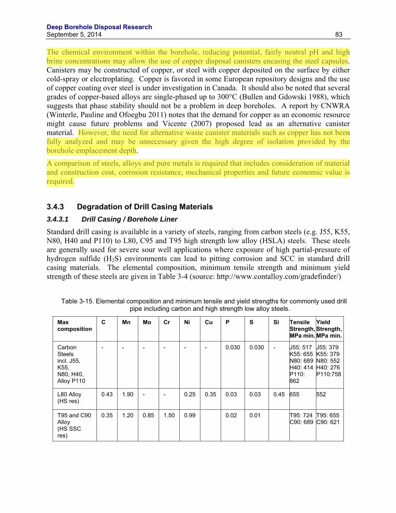
Deep Borehole Disposal Research September 5, 2014 83
The chemical environment within the borehole, reducing potential, fairly neutral pH and high brine concentrations may allow the use of copper disposal canisters encasing the steel capsules. Canisters may be constructed of copper, or steel with copper deposited on the surface by either cold-spray or electroplating. Copper is favored in some European repository designs and the use of copper coating over steel is under investigation in Canada. It should also be noted that several grades of copper-based alloys are single-phased up to 300°C (Bullen and Gdowski 1988), which suggests that phase stability should not be a problem in deep boreholes. A report by CNWRA (Winterle, Pauline and Ofoegbu 2011) notes that the demand for copper as an economic resource might cause future problems and Vicente (2007) proposed lead as an alternative canister material. However, the need for alternative waste canister materials such as copper has not been fully analyzed and may be unnecessary given the high degree of isolation provided by the borehole emplacement depth.
A comparison of steels, alloys and pure metals is required that includes consideration of material and construction cost, corrosion resistance, mechanical properties and future economic value is required.
3.4.3 Degradation of Drill Casing Materials 3.4.3.1 Drill Casing / Borehole Liner
Standard drill casing is available in a variety of steels, ranging from carbon steels (e.g. J55, K55, N80, H40 and P110) to L80, C95 and T95 high strength low alloy (HSLA) steels. These steels are generally used for severe sour well applications where exposure of high partial-pressure of hydrogen sulfide (H2S) environments can lead to pitting corrosion and SCC in standard drill casing materials. The elemental composition, minimum tensile strength and minimum yield strength of these steels are given in Table 3-4 (source: http://www.contalloy.com/gradefinder/)
Table 3-15. Elemental composition and minimum tensile and yield strengths for commonly used drill
pipe including carbon and high strength low alloy steels.
Max composition
C Mn Mo Cr Ni Cu P S Si Tensile Strength, MPa min.
Yield Strength, MPa min.
Carbon Steels incl. J55, K55, N80, H40, Alloy P110
- - - - - - 0.030 0.030 - J55: 517 K55: 655 N80: 689 H40: 414 P110: 862
J55: 379 K55: 379 N80: 552 H40: 276 P110:758
L80 Alloy (HS res)
0.43 1.90 - - 0.25 0.35 0.03 0.03 0.45 655 552
T95 and C90 Alloy (HS SSC res)
0.35 1.20 0.85 1.50 0.99 0.02 0.01 T95: 724 C90: 689
T95: 655 C90: 621
Deep Borehole Disposal Research 84 September 5, 2014
Based on tensile and compressive stress calculations for a number of borehole steel drill casing materials examined in Hoag (2006), C95 or T95 alloy is required to support a 2 km DZ in a 4 km borehole using a reference design PWR waste string of ~921 metric tons (resulting in a tensile stress of 720 MPa). For Cs/Sr capsules, the waste string mass (capsules, contents and waste canisters) requires calculation to determine whether L80 alloy is suitable in addition to C90 and T95 alloys. In addition, Hoag (2006) references Berger and Anderson (1992) suggesting that H40, J55 or K55 conductor casing and surface casing could be used with H40 final casing and J55 or P110 casing for the waste string.
In addition to tensile and compressive stresses, other important factors to consider when selecting drill casing for a deep borehole liner include phase stability and aging, SCC, hydrogen embrittlement, and microbially influenced corrosion. Delamination should also be considered as a degradation mechanism.
While phase stability is not a significant issue for the drill casing materials at temperatures predicted for deep boreholes (185°C), long-term aging of the drill casing at elevated temperatures (50-250°C) is potential concern, especially when considering the long time-periods involved in deep borehole disposal. Over the course of 300-1000 years, precipitation of carbides and inter-metallic compounds can occur, which may adversely reduce the passivity. It is important to note here that this is also a major concern for SS316L and C276 alloys.
Microbially influenced corrosion (MIC), particularly by the action of sulfate-reducing bacteria that can exist in anoxic environments is known to affect stainless steels, austenitic alloys, carbon steels and high-strength low-alloy steels. However, the effects of MIC tend to decrease above 65°C (Kumar and Anand 1998) and the bacteria are typically neutralized at approximately 95°C (Kallmeyer and Boetius 2004). Since borehole emplacement temperatures are likely to remain above 100°C due to geothermal temperatures alone, the likelihood of MIC affecting drill casing in the emplacement zone (or disposal canisters and capsules for that matter) is low.
Hydrogen embrittlement (HE) is caused by atomic hydrogen from the environment (formed by electrons generated during a corrosion process reacting with hydrogen ions from water) entering the steel. HE is one of the major corrosion mechanisms for high-strength low alloy steels. At relatively low temperatures, the atomic hydrogen in the steel combines with other atoms of hydrogen, forming hydrogen gas bubbles. As more gas bubbles form, the pressure inside the metal structure increases causing reduced ductility and tensile strength, finally resulting in the formation of cracks. At higher temperatures, the hydrogen atom combines with carbon in the steel to form methane. The HE process in steel is most susceptible at ambient temperatures and tends to decrease at higher temperatures such as those experienced in deep boreholes. The presence of chloride brines can greatly increase the general corrosion of steels, which in turn increases the availability of hydrogen for HE. The presence of sulfide in the borehole hinders the atomic hydrogen recombination reaction, causing more hydrogen to enter the steel and increasing HE. Generally, the higher the yield stress of the steel, the more susceptible it is to HE, making alloys such as T95 and C90 more prone to HE than carbon steels such as H40, J55 and K55.
Stress corrosion cracking requires three factors, namely (i) stress (either through weld or tensile/compressive from borehole component mass), (ii) a flaw (crack, initiation site) and (iii) a material-specific corrosive environment. A flaw can be a pre-existing condition due to poor manufacturing or can be initiated in locations where a high-stress concentration exists such as
Deep Borehole Disposal Research September 5, 2014 85
grooves or corrosion pits (Farmer et al. 1999). The highly concentrated brine solutions present in a deep borehole are certainly capable of causing a corrosive environment for some steels (including carbon steels), but high-strength low-alloys steels such as T95, C90 and L80 are not particularly susceptible to chloride-induced SCC. A greater concern for these alloys, particularly in the anoxic environment of the emplacement zone in deep boreholes is HE or MIC together with stress causing “environmentally assisted cracking.”
The possibility of the formation of lamellar corrosion products through the exfoliation/delamination of the drill casing or waste canister has been proposed. This process occurs when the corrosion products (metal oxides) become several time greater in volume that the original metal, leading to the formation of internal tensile stresses which effectively tear apart the material into sheets (lamella). The layers between each sheet may serve as a vertical pathway for radionuclides within the borehole perimeter. Delamination can also occur due to differences in thermal expansion of oxides and metal. This type of corrosion is considered to be unlikely to occur on the surface both 316L stainless steel and C-276 alloy. Low alloy steels such as those proposed for drill casing (e.g. L80 and T95) are susceptible to delamination. Furthermore, steels fabricated by extrusion or rolling contains flat or elongated grains, which are prone to inter-granular corrosion, and thus leading to lamellar corrosion products. However, given the anoxic potentials considered for deep boreholes, it is unlikely that delamination will occur in any of the metals down borehole because of the absence of oxygen (and therefore the absence of oxide corrosion products).
Deep Borehole Disposal Research 86 September 5, 2014
4. BOREHOLE SEALS RESEARCH AND PLANNING Borehole seals work in FY2014 focused on long-term seals degradation, alternative seals, and seals testing planning for the deep borehole field test. LLNL worked to identify the factors controlling long-term degradation of bentonite, cement, and asphalt (Section 4.2). MIT’s NEUP deep borehole project examined alternative cements. Olympic Research’s Small Business Innovative Research-funded research focused on using thermite plugs to seal boreholes. Work at Sheffield University in the United Kingdom expanded the analysis of rock-welding of boreholes.
4.1 Review of Seals Alternatives MIT developed analytical models of porous and laminar flows showing that even when materials have low intrinsic permeability, micron sized cracks and gaps between the plug and rock (formed via chemical reaction, shrinkage, osmotic consolidation, etc.) can significantly diminish borehole plug sealing properties. As an alternative to materials such as asphalt, traditional cements and pure bentonite, which crack or shrink under certain conditions, expanding cement mixtures containing MgO were examined. These findings favor using stable, malleable, and low permeability plug material (k ~ 10-16 m2), such as a 70%-30% mixture of crushed rock and bentonite. Alternative clays such as sepiolite could be blended with the bentonite to limit the potential negative effects of salinity on bentonite permeability. A bounding and analytical model of a scenario where radionuclide escape is determined by advection through the plug (and assuming a large and constant driving pressure) shows that a plug permeability of 10-16 m2 is sufficiently low to prevent advective transport of radionuclides from a depth of 2-3 km to the surface within the time scale of interest (~1 million years). Purely diffusive transport over the same distance, whether through the plug or host rock, is conservatively estimated to be significant only for a time >850,000 years.
The Olympic Research thermal plug development project was completed in March, 2014. The technology uses a thermite-based composition to form net shape high performance plugs at depth, under water. The emplacement environments of deep plug applications in nuclear waste boreholes and commercial wells were evaluated, scoping simulations predicted the thermal response of the plug and media after emplacement, and a range of exploratory and scaled tests evaluated reaction rates and final plug properties. The viability assessment demonstrated formulations capable of achieving high compressive strength (three times that of well cement), low permeability with the inherent corrosion resistance and characteristics of alumina and silica matrices at elevated temperatures. The Phase II effort, expected to start in August 2014 and run for two years, will refine the formulation chemistry, characterize and optimize plug performance under the anticipated conditions in uncased and cased wells, develop packaging and ignition system designs, and demonstrate prototype system performance in a field scale test at depth.
4.2 Chemical, Mineralogical, and Physical Stability of Borehole Seals
The two key phenomena that affect the mechanical stability of borehole seals (and hence their performance in preventing both flow of pore water to the waste canister and release of
Deep Borehole Disposal Research September 5, 2014 87
radionuclides to the environment) are the temperature and chemical environment in contact with the seals. These phenomena are evaluated with respect to various alternative designs for cement, bentonite and asphalt seals. Bentonite seals have many advantageous properties, including low permeability, high sorption capacity, self-sealing characteristics and durability (Brady et al., 2009). Above the emplacement zone, the use of bentonite, asphalt and concrete is considered (Brady et al. 2009), as is the method proposed by Gibb et al. (2008b) of using crushed host-rock. Concrete has low permeability and is widely used in hydraulic applications including sealing the wellbore to host-rock and surface. The extensive review of Pabalan et al. (2009) discusses important characteristics of cement degradation relevant to engineered barriers used in radioactive waste disposal. Asphalt is used to prevent water migration down the borehole and its properties include strength, adhesion, water-resistant, durability, and plasticity (Brady et al. 2009). Additional sealing concepts including emplacement zone metallic backfill (e.g. lead-based alloys) for lower temperature designs and waste canisters with a high specific gravity (8-11), (Gibb 2008b) and a slurry of granite resulting in partial rock melting and recrystallization in higher temperature designs (Gibb 2008c) are not considered in this review.
The temperature gradient for deep borehole disposal may range from ambient temperature at the surface to 75°C in the upper portion and 150-200°C in the emplacement zone. The effects of such temperatures on asphalt and cement seals is expected to be minimal. However, the drying of bentonite at these temperatures will lead to shrinking and cracking in unsaturated zones. In deeper regions of the borehole, above temperatures usually associated with clay dehydration under less harsh conditions, hydrostatic pressure should prevent hydrated bentonite from drying and cracking.
The volume of bentonite is reduced over time during conditions likely to occur in a deep borehole. The high ionic strength associated with deep brines and the presence of divalent cations including Ca2+, Mg2+ and Fe2+ from the host rock (and additionally Fe2+ and Ni2+ from the anoxic corrosion of drill casing) cause displacement of cations in the sheet silicates of clay. The resulting shrinkage of bentonite can lead to voids in the seal, allow potentially harmful brines to reach the waste canister, and allow the migration of radionuclides from the waste form. Additionally, the impact of cement leachate (resulting in a high pH conditioned solution of mono- and di-valent cations including Na+, K+ and Ca2+) may play in important role in the long-term chemical stability of bentonite. Recent work by Caporuscio et al. (2014) in which bentonite was placed in contact with Opalinus clay host rock, groundwater and metal coupons (including 316 stainless steel) at elevated temperatures (120 to 300°C) and pressures (≤ 16 MPa) showed a decrease in the pH, K+ and Ca2+ concentrations in porewater and an increase in aqueous silica, sodium and sulfate. Caporuscio et al. (2014) also noted that reaction kinetics were accelerated under water saturation and that illitization did not occur within the bentonite fraction. Additional work proposed by Caporuscio (2014), particularly including the use of both mafic (amphibolites) and silicic (granitic gneiss) end-members, would provide key data that could integrate geochemical modeling efforts from other areas of the UFD campaign.
Cement can undergo both chemical and physical degradation. Chemical degradation may include reaction with gaseous or dissolved carbon dioxide (carbonation) leading to precipitation of CaCO3 and consequently a reduction in the ratio of Ca:Si in the calcium-silicate-hydrate (CSH) matrix. Pabalan (2009) points out that while carbonation does not have a significant macro-structural effect, the indirect effect is a reduction in pH buffering from cement, which can adversely influence steel corrosion. Sulfate ions can also lower the Ca:Si ratio by precipitation
Deep Borehole Disposal Research 88 September 5, 2014
of calcium sulfate minerals (and magnesium hydroxide in the presence of a source of Mg2+ ions), which are generally larger in volume than the CSH matrix, resulting in expansion, disintegration and loss of strength, termed “sulfate attack” (Pabalan 2009). Carbonation and sulfate attack represent potentially the most relevant chemical degradation mechanisms in a deep borehole environment. The processes are further described in Poole et al. (1993), Tumidajski and Chan (1996) and Wakeley et al. (1993). Such processes are not well understood at temperatures, pressures and brine concentrations at emplacement depth. Recent work by Carroll et al. (2011) and Walsh et al. (2014) have combined experimental studies and modeling to understand such processes relevant to geologic carbon sequestration conditions, and the work highlights the need for close integration between deep borehole disposal and other areas of deep geologic exploration, including oil, gas, geothermal and carbon sequestration.
Other chemical degradation mechanisms of cement include leaching of soluble components, such as Ca(OH)2 and minerals of silicate and aluminate, enhanced by neutral to low pH. Corrosion of steel products in the vicinity of cement may also lead the formation of iron oxides of higher volume that in turn cause cracking and loss of strength similar to carbonation.
The basis for cement longevity at the Waste Isolation Pilot Plant (WIPP) was determined for borehole plugs in experiments conducted by Thompson et al. (1996) who found that plug failure occurred when the CSH matrix undergoes measurable alteration. Thompson et al. (1996) also concludes that in a 3-plug borehole design, deeper casing corrosion will be less severe than upper sections and that deeper plugs (e.g. 4 km) will not fail for approximately 5,000 years.
Asphalt is primarily a complex mixture of high molecular-weight hydrocarbons, sometimes containing compounds of iron, silicon and aluminum. Aggregates may be used in asphalt to add strength and may include granite amongst other minerals. Asphalt is widely used (and greatly researched) in terms of road construction, and asphalt has been used for many centuries. Stieter and Snoke (1936) observed the formation of water-soluble asphalt degradation products in the presence in oxic environments exposed to light. However, the relatively benign upper environment in the top 250 to 500 m of the borehole, where asphalt might be used as a plug, precludes UV light from breaking down the organic constituents in asphalt, while any contacting water will be dilute in nature rather than the concentrated brines observed in the emplacement zone, and conditions will be mildly anoxic. Such conditions will prevent the degradation of asphalt for a long period of time. Microbial activity is known to degrade asphalt, with chemical environment, pH and redox conditions affecting the growth and effects (Phillips and Traxler, 1963). Additionally, the organic content of the asphalt may provide nutrients for microbes to grow, and the sulfur present in asphalt may provide a source for sulfate-reducing bacteria known to promote MIC. Degradation studies of asphalt under borehole conditions (particularly in regard to MIC) are recommended.
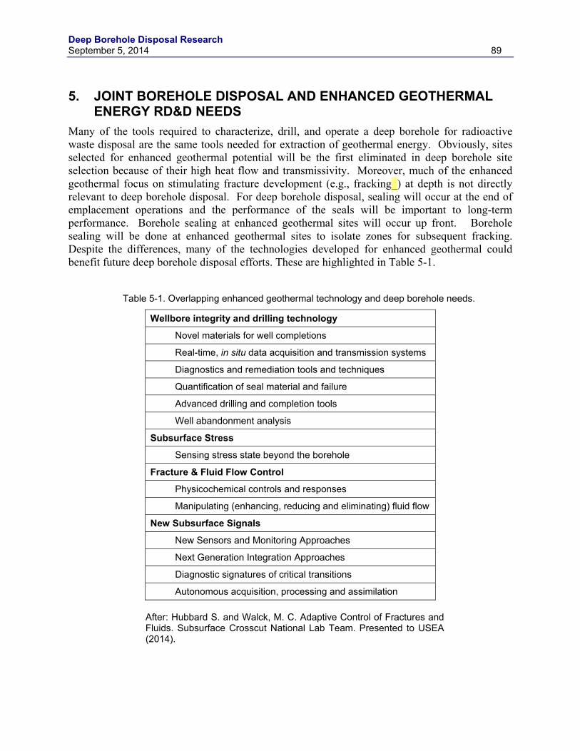
Deep Borehole Disposal Research September 5, 2014 89
5. JOINT BOREHOLE DISPOSAL AND ENHANCED GEOTHERMAL ENERGY RD&D NEEDS
Many of the tools required to characterize, drill, and operate a deep borehole for radioactive waste disposal are the same tools needed for extraction of geothermal energy. Obviously, sites selected for enhanced geothermal potential will be the first eliminated in deep borehole site selection because of their high heat flow and transmissivity. Moreover, much of the enhanced geothermal focus on stimulating fracture development (e.g., fracking_) at depth is not directly relevant to deep borehole disposal. For deep borehole disposal, sealing will occur at the end of emplacement operations and the performance of the seals will be important to long-term performance. Borehole sealing at enhanced geothermal sites will occur up front. Borehole sealing will be done at enhanced geothermal sites to isolate zones for subsequent fracking. Despite the differences, many of the technologies developed for enhanced geothermal could benefit future deep borehole disposal efforts. These are highlighted in Table 5-1.
Table 5-1. Overlapping enhanced geothermal technology and deep borehole needs.
Wellbore integrity and drilling technology
Novel materials for well completions
Real-time, in situ data acquisition and transmission systems
Diagnostics and remediation tools and techniques
Quantification of seal material and failure
Advanced drilling and completion tools
Well abandonment analysis
Subsurface Stress
Sensing stress state beyond the borehole
Fracture & Fluid Flow Control
Physicochemical controls and responses
Manipulating (enhancing, reducing and eliminating) fluid flow
New Subsurface Signals
New Sensors and Monitoring Approaches
Next Generation Integration Approaches
Diagnostic signatures of critical transitions
Autonomous acquisition, processing and assimilation
After: Hubbard S. and Walck, M. C. Adaptive Control of Fractures and Fluids. Subsurface Crosscut National Lab Team. Presented to USEA (2014).

Deep Borehole Disposal Research 90 September 5, 2014
All evidence indicates that deep borehole disposal can be demonstrated with existing technology. The technology thrusts outlined in Table 5-1, if developed and proven in the field, might expand the number of tools available for deep borehole disposal.
Deep Borehole Disposal Research September 5, 2014 91
6. SUMMARY AND CONCLUSIONS Research efforts in the deep borehole disposal work package in FY2014 are principally directed at advancing the deep borehole disposal project to the implementation of a full-scale Research, Development, and Demonstration (RD&D) project in the form of a field test. The scope of the work package consists of four tasks: (1) evaluation of regional and sub-regional geotechnical and other information that could support siting of the field test project, (2) development of reference designs for disposal of alternative waste forms, (3) borehole seals research and planning, and (4) review of RD&D needs overlapping with enhanced geothermal energy research.
Three locations were selected for more detailed sub-regional scale evaluations as potential areas for siting a deep borehole field test. These locations, not limited to DOE sites, were selected as being representative of a range of geological conditions and geographical locations that appear potentially favorable for the field test.
The location in northeast South Dakota is broadly representative of geological conditions in the central U.S. outside of major sedimentary basins and has a sedimentary cover of generally less than 1,000 m over Precambrian age crystalline basement rocks, many of which are Archean in age. This area has numerous favorable factors, including existing data and geological interpretation relevant to site selection guidelines. The Benson Block in the Precambrian basement appears to be a particularly favorable terrane for a deep borehole field test because of probable large granitic batholiths present in the detailed study area. Crystalline rocks of the Archean Superior Craton, such as those inferred to exist in the Benson Block, have been tectonically stable for very long periods of time and have been shown to contain fracture fluids older than 1 billion years at other locations.
The location in the Texas Panhandle has sedimentary cover of highly variable thickness over Precambrian age crystalline rocks from the Proterozoic Eon and is generally representative of more structurally complex geological conditions along and within the margins of sedimentary basins to the east of the Rocky Mountains. Parts of the Texas Panhandle have geological characteristics that are favorable for siting the deep borehole field test, although several geological factors are highly variable within this subregion, with depths to crystalline basement varying from less than 500 m to greater than 7,000 m. The Pantex Plant site is located on the southern margin of the Amarillo Uplift in an area with a faulted structural trough in the Precambrian basement, little nearby borehole data, and significant uncertainty in depth and nature of the crystalline basement. Other factors are generally favorable for the field test.
The location in South Carolina has sedimentary cover of mostly less than 700 m over lithologically diverse basement rocks of Paleozoic and Mesozoic age, including non-crystalline rock types in some areas, and is broadly representative of the Piedmont and Coastal Plain environment of the southeastern U.S. This area includes the Savannah River Site and nearby locations have some favorable conditions for siting the deep borehole field test; however geological conditions in this area deviate from the basic deep borehole disposal concept because basement rocks are lithologically diverse and geologically younger than Precambrian crystalline rocks. Basement rocks in this area are dominated by metamorphic rocks of varying metamorphic grade, but also consist of clastic sedimentary rocks in rift basins and both felsic and mafic igneous intrusions. A thick sequence of clastic sedimentary rocks would be unfavorable for demonstration of the deep borehole disposal concept. Little is known about fluid characteristics
Deep Borehole Disposal Research 92 September 5, 2014
in the deep basement geological environment of the Atlantic Coastal Plain, relative to somewhat greater knowledge on the topic from the Precambrian basement in central North America.
Overall, the location is northeastern South Dakota appears to be more favorable for the deep borehole field test than Pantex Plant Site and the Savannah River Site. However, locations within the regions near the Pantex Plant and the Savannah River site may be somewhat more attractive than at the DOE sites specifically.
A preliminary screening of all DOE sites for suitability to host a deep borehole field test was also conducted. Demonstrating deep borehole technology at a DOE site has several potential advantages, including a wide range of geographic locations from which to choose and infrastructure to support technology demonstration. Sites were scored on the basis of a number of factors, including depth to crystalline basement, proximity to urban areas, geothermal heat flux, seismicity, regional topographic relief, and Quaternary volcanism and faulting, in part. Results of the screening identified four primary higher ranking sites (Maxey Flats, Hallam Nuclear Power Facility, Savannah River Site, and Knolls Atomic Power Laboratory), and five secondary high ranking sites (Luckey Site, Spook UMTRA Site, Pantex Plant, Tuba City UMTRA Site, and West Valley Demonstration Project).
The DOE is evaluating policy options for the management and permanent disposal of a broad range of radioactive waste types, including SNF and HLW. The DOE (2014) study on waste disposal options concluded that deep borehole disposal may be a feasible and potentially attractive option for the disposition of cesium and strontium capsules and untreated calcine waste. Deep borehole disposal system design options for disposition of these waste forms were analyzed in this report. The baseline system design for cesium and strontium capsules consists of a ~1,300 m disposal zone containing 968 waste canisters, each holding two cesium and/or strontium capsules, in a ~5,000 m deep borehole that is 8.5 inches in diameter at depth and drilled and completed for an estimated cost of $17.4 M. The entire inventory of Cs and Sr capsules could be disposed in a single borehole with this design.
Thermal simulations of the deep borehole disposal system for the Cs and Sr capsules were conducted using a high resolution model to estimate temperatures within and near the waste canisters. Results indicate that peak temperatures in the capsules occurs within a few years of waste canister emplacement in the borehole and are generally below 200 ºC for the variations in thermal output, number of canisters, and grout considered in the modeling cases. Filling the annulus around the waste canisters with crushed granite resulted in higher peak temperatures than with bentonite fill. Thermal-hydrologic modeling for disposal of the Cs and Sr capsules was performed to estimate the circulation of groundwater induced by waste heat from a single disposal borehole. Simulated vertical groundwater flow rates in the borehole and disturbed rock zone indicate upward groundwater flux of less than 1 cm/year for several decades followed by a rapidly decreasing flow rates for later times. These low simulated upward flow rates, the sorptive nature of cesium and strontium, and the relatively short half lives of Cs-137 and Sr-90 suggest that releases to the biosphere would be negligible.
Direct disposal of untreated calcine waste was analyzed for deep borehole disposal in the reference design borehole with a diameter of 17 inches at depth. Disposal of the 4,400 m3 of untreated calcine would require about 29,550 waste canisters and 74 boreholes.
Degradation of Cs and Sr waste forms and capsules, waste canister materials, and borehole casing/liner materials was analyzed under relevant chemical and thermal conditions. The Cs and
Deep Borehole Disposal Research September 5, 2014 93
Sr capsules have experienced different thermal environments during filling with molten salt, storage in water pools, and exposure to air during handling. The stainless steel capsules in pool storage should not have experienced significant pitting corrosion, but may have been subject to stress corrosion cracking. CsCl is highly soluble (1910 g/l at room temperature) and SrF2 is moderately low solubility (0.135 g/l at room temperature. Copper or copper-coated waste canisters would be one option that is resistant to corrosion under expected downhole chemical conditions, if corrosion resistance is a design consideration. Microbially influenced corrosion, hydrogen embrittlement, and stress corrosion cracking may potentially have significant corrosive impacts on casing and liner materials.
Borehole seals work focused on long-term seals degradation, alternative seals, and seals testing planning for the deep borehole field test. A bounding analytical model shows that radionuclide transport is determined by advection through the plug (and assuming a large and constant driving pressure) and that a plug permeability of 10-16 m2 is sufficiently low to prevent advective transport of radionuclides from a depth of 2-3 km to the surface within the time scale of interest (~1 million years). These findings favor using stable, malleable, and low permeability plug material (k ~ 10-16 m2), such as a 70%-30% mixture of crushed rock and bentonite. Alternative clays such as sepiolite could be blended with the bentonite to limit the potential negative effects of salinity on bentonite permeability. The Olympic Research thermal plug development project used a thermite-based composition to form net shape high performance plugs at depth, under water. Their viability assessment demonstrated formulations capable of achieving high compressive strength (three times that of well cement), low permeability with the inherent corrosion resistance and characteristics of alumina and silica matrices at elevated temperatures.
Many of the tools required to characterize, drill, and operate a deep borehole for radioactive waste disposal are the same tools needed for extraction of geothermal energy. General areas of overlapping technology needs include wellbore integrity and drilling technology, subsurface stress, fracture and fluid controls, and new subsurface signals technology. All evidence indicates that deep borehole disposal can be demonstrated with existing technology. These overlapping technology thrusts, if developed and proven in the field, might expand the number of tools available for deep borehole disposal.
Deep Borehole Disposal Research 94 September 5, 2014
7. REFERENCES
Anderson, V.K. 2004, An Evaluation of the Feasibility of Disposal of Nuclear Waste in Very Deep Boreholes, Thesis, MIT Department of Nuclear Science and Engineering, Sept. 2004.
Arnold, B.W., P.V. Brady, S.J. Bauer, C. Herrick, S. Pye, and J. Finger, 2011a, Reference Design and Operations for Deep Borehole Disposal of High-Level Radioactive Waste. SAND2011-6749. Albuquerque, NM: Sandia National Laboratories.
Arnold, B.W., T. Hadgu, D. Clayton, and C. Herrick, 2011b, Thermal-hydrologic-chemical-mechanical modeling of deep borehole disposal, Proceedings of the 13th International High Level Radioactive Waste Management Conference, Albuquerque, New Mexico, April 10-14, 2011, American Nuclear Society, La Grange Park, IL.
Arnold, B. and T. Hadgu, 2013, Thermal-hydrologic modeling of a deep borehole disposal system, Proceedings of the 14th International High-Level Radioactive Waste Management Conference, April 28-May 2, 2013, Albuquerque, NM.
Attrill, P.G. and F.G.F. Gibb, 2003a, Partial melting and recrystallization of granite and their application to deep disposal of radioactive waste. Part 1 – Rationale and partial melting. Lithos, 67, 103-117.
Beswick, J., 2008, Status of Technology for Deep Borehole Disposal. Report for the Nuclear Decommisioning Authority by EPS International Contract No. NP01185.
Beswick, A.J., F.G.F. Gibb, K.P. Travis, 2014, Deep borehole disposal of nuclear waste: engineering challenges. Proceedings of the Institution of Civil Engineers, Energy, 167, 47-66.
Bankey, V., 2006, Texas Magnetic and Gravity Maps and Data: A Website for Distribution of Data, Data Series 232, U.S. Geological Survey, http://pubs.usgs.gov/ds/2006/232/ [Accessed 2014].
Bates, E.A., M.J. Driscoll, R.K. Lester, and B.W. Arnold, 2014, Can deep boreholes solve America’s nuclear waste problem, Energy Policy, in press.
Berger, B.D. and K.E. Anderson, 1992, Modern Petroleum - A Basic Primer of the Industry, PennWell Publishing Company, Tulsa, Oklahoma.
Beswick, John, 2008, Status of Technology for Deep Borehole Disposal, Contract NP 01185, EPS International.
Bird, R.B, W.E. Steward and E.N. Lightfoot, 2002, Transport Phenomena, 2nd Edition.
Brady, P.V., B.W. Arnold, G.A. Freeze, P.N. Swift, S.J. Bauer, J.L. Kanney, R.P. Rechard, J.S. Stein, 2009, Deep Borehole Disposal of High-Level Radioactive Waste, SAND2009-4401, Albuquerque, NM, Sandia National Laboratories.
Bryan, G.H., D.R. Olander and G.L. Tingey, 2003, Corrosion Report for Capsule Dry Storage Project, WMP-16937, September 2003 Fluor Hanford Inc., Richland, Washington.
Bullen, D.B. and G.E. Gdowsk,i 1988, Survey of Degradation Models of Candidate Materials for High-Level Radioactive-Waste Disposal Canisters: Phase Stability, UCID-21362 Vol.1, August 1988, Lawrence Livermore National Laboratory, Livermore, California.
Deep Borehole Disposal Research September 5, 2014 95
Caporusico, F.A., M.C Cheshire, M.S. Rearick and C. Jove-Colon, 2014, LANL Argillite EBS Experimental Program 2014, FCRD-UFD-2014-000491 (LA-UR-14-25179), July 2014, Los Alamos National Laboratory (LANL), Los Alamos, New Mexico.
Carroll. S.A., W.W. McNab and S.C. Torres, 2011, Experimental study of cement - sandstone/shale – brine – CO2 interactions, Geochemical Transactions 12.
Chapman, M.C. and P. Talwani, 2002, Seismic Hazard Mapping for Bridge and Highway Design, South Carolina Department of Transportation.
Cochran, J.R.; W.E. Beyeler; D.A. Brosseau; L.H. Brush; T.J. Brown; B. Crowe; S.H, Conrad; P.A. Davis; T. Ehrhorn; T. Feeney; B. Fogleman; D.P Gallegos; R. Haaker; E. Kalinina; L.L. Price; D.P. Thomas; and S. Wirth, 2001. Compliance Assessment Document for the Transuranic Wastes in the Greater Confinement Disposal Boreholes at the Nevada Test Site. SAND2011-2977, September, 2001.
Covey, L.I., 2012, Waste Encapsulation and Storage Facility Documented Safety Analysis, DSA HNF-8758-07, Revision 7, Chapter 2, CH2MHill Plateau Remediation Company, Richland, Washington.
Cumbest, R.J., D.E. Stephenson, D.E. Wyatt, M. Maryak, 1998, Basement Surface Faulting and Topography for the Savannah River Site and Vicinity, WSRC-TR-98-00346, Westinghouse Savannah River Company, Aiken, South Carolina.
Daniels, D.L., 2005, South Carolina Aeromagnetic and Gravity Maps and Data: A Web Site for Distribution of Data, Open-File Report 2005-1022, U.S. Geological Survey, http://pubs.usgs.gov/of/2005/1022/ [Accessed 2014].
Defense and Nuclear Facilities Safety Board (DNFSB), 1995, Hanford – B Plant/Waste Encapsulation and Storage Facility Review, Defense Nuclear Facilities Safety Board, Washington DC.
Defense and Nuclear Facilities Safety Board (DNFSB), 1996, Trip Report—Safety of Cesium and Strontium Capsules at Hanford. Washington, D.C.: Defense Nuclear Facilities Safety Board. June 7th.
Denham, M.E., 1995, SRS Geology/Hydrology Environmental Information Document, WSRC-TR-95-0046, Westinghouse Savannah River Company, Aiken, South Carolina.
Domoracki, W.J., 1995, A Geophysical Investigation of Geologic Structure and Regional Tectonic Setting at the Savannah River Site, South Carolina, Ph.D. Dissertation, Virginia Polytechnic Institute and State University.
Driscoll, M.J., R.K. Lester, K.G. Jensen, B.W. Arnold, P.N. Swift, and P.V. Brady, 2012, Technology and policy aspects of deep borehole nuclear waste disposal, Nuclear Technology, vol. 180, no. 1, pp. 111-121.
Duff, P., J. Kellogg, S. Howard, and J.W. Horton, 2013, Mapping the buried basement of the Coastal Plain, southern Atlantic margin of eastern North America, poster, Geological Society of America Meeting 2013.
Dutton, S.P., A.G. Goldstein, and S.C. Ruppel, 1982, Petroleum Potential of the Palo Duro Basin, Texas Panhandle, Report of Investigations No. 123, The University of Texas, Bureau of Economic Geology,
Deep Borehole Disposal Research 96 September 5, 2014
Farmer, J., D. McCright, J-S. Huang, A. Roy, K. Wilfinger, R. Hopper, F. Wang, P. Bedrossian, J. Estill and J. Horn February, 1999, Development of Integrated Mechanistically-Based Degradation Model Models for Performance Assessment of High-Level Waste Containers, UCRL-ID-130811 Rev 1, Lawrence Livermore National Laboratory, Livermore California.
Fluor, 2003, Performance Specification for Capsule Dry Storage Project Design and Fabrication, HNF-16138 Rev 1, Fluor Hanford Inc., Richland, Washington.
Frontier Associates LLC, 2008, Texas Renewable Energy Resource Assessment, Texas State Energy Conservation Office.
Fullam, H.T., 1976, The Solubility and Dissolution Behavior of 90SrF2 in Aqueous Media, Battelle Pacific Northwest Laboratories report BNWL-2101, Richland Washington
Gibb, F.G.F., K.J. Taylor, and B.E. Burakov, 2008a, The ‘granite encapsulation’ route to the safe disposal of Pu and other actinides, Journal of Nuclear Materials. Vol. 374, No. 3, pp. 364–369.
Gibb, F.G.F., N.A. McTaggart, K.P. Travis, D. Burley and, K.W. Hesketh, 2008b, High-density support matrices: Key to the deep borehole disposal of spent nuclear fuel, Journal of Nuclear Materials, Vol. 374, pp. 370–377.
Gibb, F.G.F., N.A. McTaggart, K.P. Travis, and D. Burley. 2008c. A model for heat flow in deep borehole disposals of high-level nuclear wastes. Journal of Geophysical Research, 113, http://dx.doi.org/10.1029/2007JB005081.
Gibb, F.G.F., K.P. Travis and K.W. Hesketh, 2012, Deep borehole disposal of higher burn up spent nuclear fuels. Mineralogical Magazine, 76, 3003-3017.
Haynes, W.M. (ed), 2014-2015, Handbook of Chemistry and Physics 95th Ed 2014-2015, CRC, available at http://www.hbcpnetbase.com/ .
Heard, F.J., K.R. Robertson, J.E. Scott, M.G. Plys, S.J. Lee, and B. Malinovic, 2003, Thermal Analysis of a Dry Storage Concept for Capsule Dry Storage Project, WMP-16940, Flour Hanford, Richland, Washington.
Hoag, C.I., 2004, Canister Design of Deep Borehole Disposal of Nuclear Waste, Thesis, MIT Department of Nuclear Science and Engineering.
Hodgkinson, D. P., 1977, Deep Rock Disposal of High Level Radioactive Waste: Transient Heat Conduction from Dispersed Blocks, Report R8783, Atomic Energy Research Establishment, Harwell, UK.
Holland, G., B. Sherwood Lollar, L. Li, G. Lacrampe-Couloume, G.F. Slater, and C.J. Ballentine, 2013, Deep fracture fluids isolated in the crust since the Precambrian era, Nature, 497, 357. doi:10.1038/nature12127.
Johnson, K.S., 2013, Preliminary Assessment of the Character and Depth of Basement Rocks on the Amarillo Uplift in Parts of the Texas Panhandle, personal communication.
Kallmeyer, J. and A. Boetius, 2004, Effects of temperature and pressure on sulfate reduction and anaerobic oxidation of methane in hydrothermal sediments of Guaymas Basin, Applied Environmental Microbiology 70(2):1231.
Kumar, C. and S. Anand, 1998, Significance of microbial biofilms in food industry: a review. International Journal of Food Microbiology, 42(9): 27.
Deep Borehole Disposal Research September 5, 2014 97
Kucks, R.P. and P.L. Hill, 2002, South Dakota Aeromagnetic and Gravity Maps and Data: A Web Site for Distribution of Data, Open-File Report 02-341, U.S. Geological Survey, http://pubs.usgs.gov/of/2002/ofr-02-0341/ [Accessed 2014].
Lee, Joon H., Bill W. Arnold, Peter N. Swift, Teklu Hadgu, Patrick V. Brady, Geoff Freeze, and Yifeng Wang, 2012, A prototype performance assessment model for generic deep borehole repository for high-level nuclear waste, proceedings of 2012 Waste Management Conference, February 26-March 1, 2012, Tucson, AZ.
Man, A and J.B. Martino, 2009, Thermal, Hydraulic and Mechanical Properties of Sealing Materials. Report NWMO TR-2009-20. Nuclear Waste Management Organization, Toronto, Canada.
McCormick, K., 2010, Precambrian Basement Terrane of South Dakota, Bulletin 41, Department of Environmental and Natural Resources, University of South Dakota.
National Research Council, 2003, Improving the Scientific Basis for Managing DOE’s Excess Nuclear Materials and Spent Nuclear Fuel, The National Academies Press, Washington, DC.
Pabalan, R.T., F.P. Glasser, D.A. Pickett, G.R. Walter, S. Biswas, M.R. Juckett, L.M. Sabido and J.L. Myers, 2009, Review of Literature and Assessment of Factors Relevant to Performance of Grouted Systems for Radioactive Waste Disposal, CNWRA 2009-001, April 2009, Center for Nuclear Waste Regulatory Analyses (CNWRA), San Antonio, Texas.
Phillips, U.A and R.W. Traxler, 1963, Microbial degradation of asphalt, Applied Microbiology, 11(3):235.
Plys, M.G. abd W.C. Miller, 2003, Summary Report for Capsule Dry Storage Project, WMP-17265, Fluor Hanford, Richland, WA.
Poole, T.S., L.D. Wakeley and C.L. Young, 1993, Individual and Combined Effects of Chloride, Sulfate, and Magnesium Ions on Hydrated Portland-Cement Paste, SAND93-7040, Sandia National Laboratories, Albuquerque, New Mexico.
Randklev, E., 1994, Disposal of Hanford Site Cesium and Strontium Capsules, presentation to the Nuclear Waste Technical Review Board (NWTRB), June 15th, 1994, TWRS Vitrification Development Tank Waste Remediation System, Westinghouse Hanford Company, Richland, Washington.
Rebak, R.B., 2006, Selection of corrosion resistant materials for nuclear waste repositories, Materials Science and Technology, Cincinatti, October 15-19, 2006. Also available as LLNL report UCRL-PROC-221893, June 8th 2006, Livermore California.
Schoon, R.A. and D.J. McGregor, 1974, Geothermal Potentials in South Dakota, Report of Investigations No. 110, South Dakota Geological Survey, Vermillion, South Dakota.
Sims, P.K., R.W. Saltus, and E.D. Anderson, 2008, Precambrian Basement Structure Map of the Continental United States—An Interpretation of Geologic and Aeromagnetic Data, U.S. Geological Survey Scientific Investigations Map 3012, scale: 1:8,000,000.
Society of Automotive Engineers (SAE), 1986, Metal and Alloys in the Unified Numbering System, 4th Edition, Society of Automotive Engineers, Inc., Warrendale, PA.
Deep Borehole Disposal Research 98 September 5, 2014
Strieter, O.G. and H.R. Snoke, 1936, A modified accelerated weathering test for asphalts and other materials, RP886, J. Research NBS, 17, 481 RP886.
Sutton, M. and H. Greenberg, 2014, FY14 Progress Report on Deep Borehole Material Degradation and Effects, DOE UFD Milestone Report M4FT-14LL0817019.
Swift, Peter N., Bill W. Arnold, Patrick V. Brady, Geoff Freeze, Teklu Hadgu, Joon H. Lee, and Yifeng Wang, 2011, Preliminary performance assessment for deep borehole HLW disposal, Radwaste Solutions, v. 18, no. 3 (July/August 2011), pp 60-65.
Thompson, T.W., W.E. Coons, J.L. Krumhansl, and F.D. Hansen, 1996, Inadvertent Intrusion Borehole Permeability, ERMS 241131. Sandia National Laboratories, Albuquerque, New Mexico.
Tingey, G.L., E.J. Wheelwright and J.M. Lytle, 1983, A Review of Safety Issues that Pertain to the use of WESF Cesium Chloride Capsules in an Irradiator, PNL-5170 July 1983, Pacific Northwest National Laboratories, Richland Washington.
Timoshenko, S., 1940, Strength of Materials, Part II.D., Van Nostrand Co., New York.
Tomhave, D.W., 1997, Geology of Spink County, South Dakota, Bulletin 38, South Dakota Geological Survey, Vermillion, South Dakota.
Tumidajski, P. J. and G.W. Chan, 1996, Durability of high performance concrete in magnesium brine: Cement and Concrete Research, v. 26, no. 4, p. 557-565.
U.S. Department of Energy (DOE), 1987, Final Environmental Impact Statement - Disposal of Hanford Defense High-level, Transuranic and Tank Wastes, 1987 EIS-0113, Volume 2 of 5, Section 3, U.S. Department of Energy, Washington, DC.
U.S. Department of Energy (DOE), 1990, Interim Report of the DOE Type B Investigation Group; Cesium-137: A Systems Evaluation, Encapsulation to Release at Radiation Sterilizers, Inc., DOE/ORO--914, July 1990, U.S. Department of Energy, Washington, DC.
U.S. Department of Energy (DOE), 2002, Waste Encapsulation Storage Facility (WESF) Fact Sheet, REG-0275, U.S. Department of Energy, Richland Operations Office (ROO), Richland, Washington.
U.S. Department of Energy (DOE), 2012, Research, Development, and Demonstration Roadmap for Deep Borehole Disposal, FCRD-USED-2012-000269, U.S. Department of Energy, Washington, DC.
U.S. Department of Energy (DOE), 2013, Deep Borehole Disposal Research: Demonstration Site Selection Guidelines, Borehole Seals Design, and RD&D Needs, FCRD-USED-2013-000409, U.S. Department of Energy, Washington, DC.
U.S. Department of Energy (DOE), 2014, Evaluation of Options for Permanent Geologic Disposal of Spent Nuclear Fuel and High-Level Radioactive Waste in Support of a Comprehensive National Nuclear Fuel Cycle Strategy, FCRD-USED-2013-000371, U.S. Department of Energy, Washington, DC.
Vaughn, P., B.W. Arnold, S.J. Altman, P.V. Brady, and W.P. Gardner, 2012, Site Characterization Methodology for Deep Borehole Disposal, SAND2012-7981, Sandia National Laboratories, Albuquerque, NM.
Deep Borehole Disposal Research September 5, 2014 99
Vicente, R., 2007, Qualitative performance assessment of a borehole disposal system, Proceedings of the Waste Management 2007 Conference, Tucson, Arizona, February 25–March 1, 2007.
Wakeley, L. D., T.S. Poole, J.J. Ernzen and B.D. Neeley, 1993, Salt Saturated Mass Concrete Under Chemical Attack, in Zia, P., ed., High Performance Concrete in Severe Environments, Volume SP-140: Detroit, MI, American Concrete Institute.
Walsh, S.D.C. H.E. Mason, W.L. Du Frane and S.A. Carroll, 2014a, Experimental calibration of a numerical model describing the alteration of cement/caprock interfaces by carbonated brine. International J. Greenhouse Gas Control, 22, 176–188.
Walsh, S.D.C. H.E. Mason, W.L. Du Frane and S.A. Carroll, 2014b, Mechanical and hydraulic coupling in cement-caprock interfaces exposed to carbonated brine. International J. Greenhouse Gas Control, 25, 109–120.
Wersin, P., L.H. Johnson and I.G. McKinley, 2007, Performance of the bentonite barrier at temperatures beyond 100ºC: A critical review. Physics and Chemistry of the Earth, 32, 780-788.
Winterle, J., R. Pauline and G. Ofoegbu, 2011, Regulatory Perspectives on Deep Borehole Disposal Concepts, Center for Nuclear Waste Regulatory Analyses (CNWRA), San Antonio, Texas, May 2011.


Deep Borehole Disposal Research September 5, 2014 A-1
Appendix A. SCREENING OF DOE SITES FOR A DEEP BOREHOLE FIELD TEST PROJECT
Section 2.2 described the procedure by which DOE sites were screened for a deep borehole demonstration. Table 2.2 listed the numerical scoring criteria and their weighting. Table A-1 lists all scores for all DOE sites.
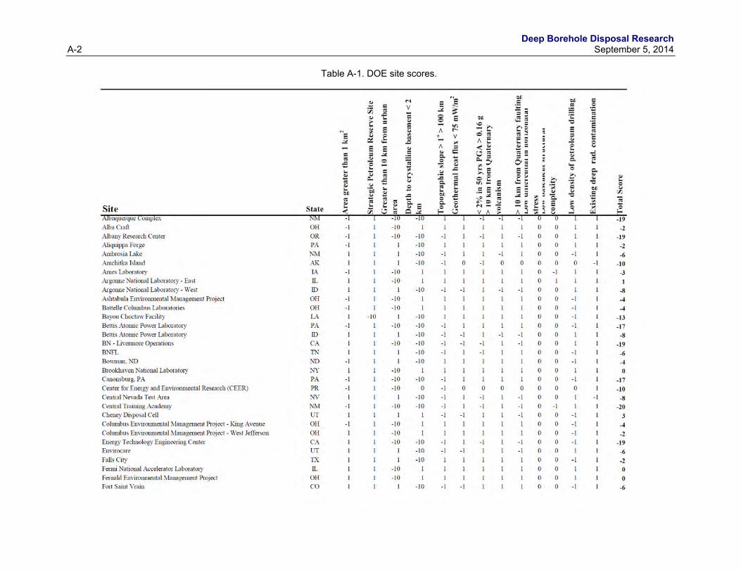
Deep Borehole Disposal Research A-2 September 5, 2014
Table A-1. DOE site scores.
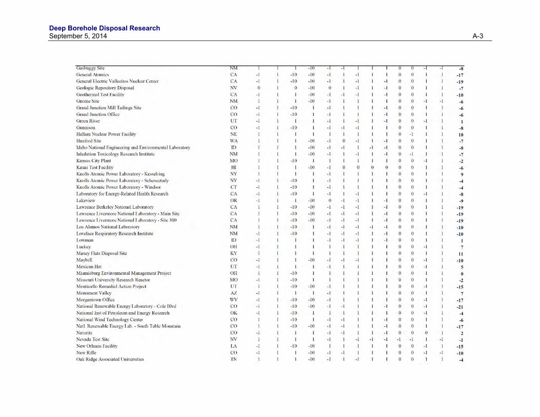
Deep Borehole Disposal Research September 5, 2014 A-3
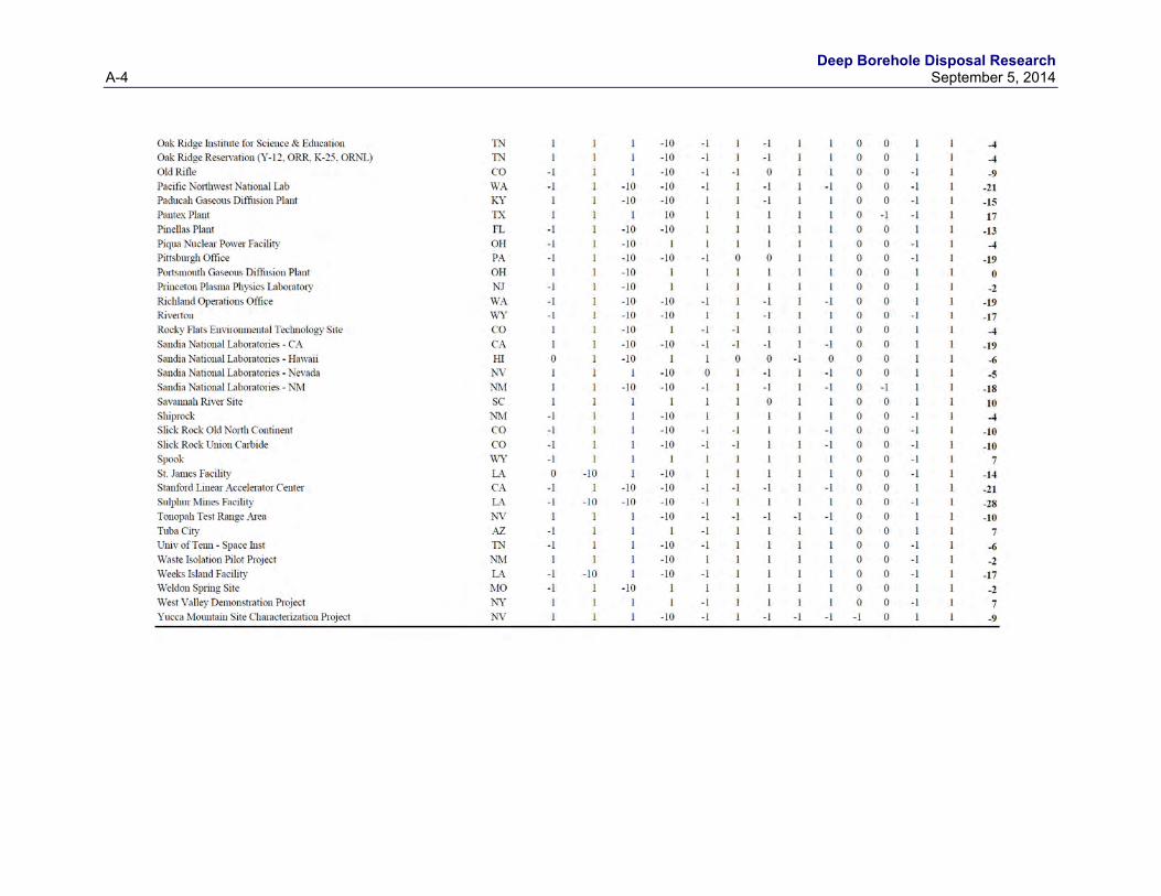
Deep Borehole Disposal Research A-4 September 5, 2014