Embed Size (px)
Citation preview

© 2012 Aker Solutions part of Aker
Deep water marine drilling CLIP riserONS 2012
Drilling risersJuly 2012Slide 1

© 2012 Aker Solutions part of Aker
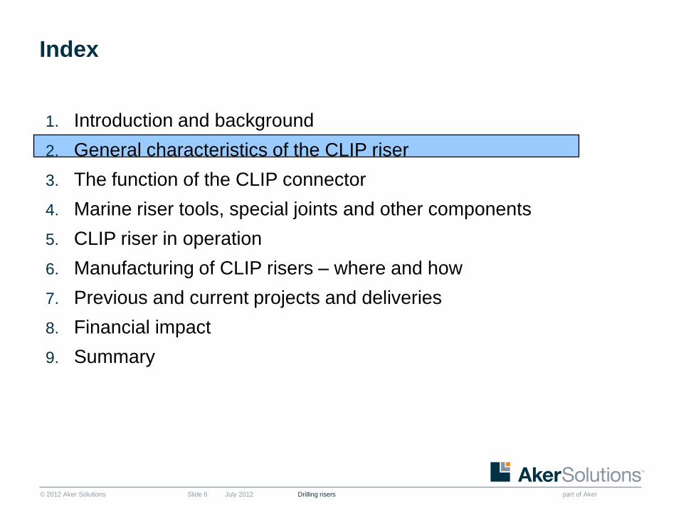
Index
July 2012 Drilling risersSlide 2
1. Introduction & Background
2. General characteristics of the CLIP Riser
3. The function of the CLIP connector
4. Marine Riser Tools, Special Joints and other Components
5. CLIP Riser in operation
6. Manufacturing of CLIP risers – where & how
7. Previous and Current Projects and Deliveries
8. Financial impact
9. Summary

© 2012 Aker Solutions part of Aker
Core values
July 2012 Drilling risersSlide 3
© 2012 Aker Solutions part of Aker
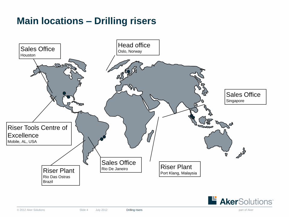
Main locations – Drilling risers
July 2012 Drilling risersSlide 4
Riser PlantPort Klang, Malaysia
Head officeOslo, Norway
Riser PlantRio Das Ostras
Brazil
Riser Tools Centre of
ExcellenceMobile, AL, USA
Sales OfficeSingapore
Sales OfficeHouston
Sales OfficeRio De Janeiro

© 2012 Aker Solutions part of Aker
Background
July 2012 Drilling risersSlide 5
■ Developed by the Institut Francais du Petrol and Framatome, a Division of Cruesot-Loire
■ Aker Solutions is licensed by IFP and Framatome to Manufacture the CLIP Riser
■ Developed Specifically for Deepwater Drilling after a 5 Year R & D Program
■ Mainly Distinguished by Breech-Block Type Connection
© 2012 Aker Solutions part of Aker
Index
July 2012 Drilling risersSlide 6
1. Introduction and background
2. General characteristics of the CLIP riser
3. The function of the CLIP connector
4. Marine riser tools, special joints and other components
5. CLIP riser in operation
6. Manufacturing of CLIP risers – where and how
7. Previous and current projects and deliveries
8. Financial impact
9. Summary
© 2012 Aker Solutions part of Aker
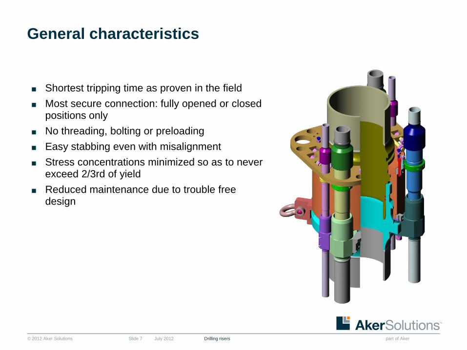
General characteristics
July 2012 Drilling risersSlide 7
■ Shortest tripping time as proven in the field
■ Most secure connection: fully opened or closedpositions only
■ No threading, bolting or preloading
■ Easy stabbing even with misalignment
■ Stress concentrations minimized so as to never exceed 2/3rd of yield
■ Reduced maintenance due to trouble freedesign

© 2012 Aker Solutions part of Aker
General characteristics
July 2012 Drilling risersSlide 8
■ Dual row of lugs provides a 360 degree
distribution of the axial load
■ Connector is a class H, 3,500,000 Lbs. API-16R
■ Up to 6 peripheral lines: hydraulic lines, kill and
choke lines, booster lines and chemical lines
■ Main tube X-80, DSAW pipe
■ H2S service kill, choke and booster lines
© 2012 Aker Solutions part of Aker
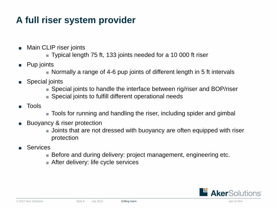
A full riser system provider
July 2012 Drilling risersSlide 9
■ Main CLIP riser joints
■ Typical length 75 ft, 133 joints needed for a 10 000 ft riser
■ Pup joints
■ Normally a range of 4-6 pup joints of different length in 5 ft intervals
■ Special joints
■ Special joints to handle the interface between rig/riser and BOP/riser
■ Special joints to fulfill different operational needs
■ Tools
■ Tools for running and handling the riser, including spider and gimbal
■ Buoyancy & riser protection
■ Joints that are not dressed with buoyancy are often equipped with riser
protection
■ Services
■ Before and during delivery: project management, engineering etc.
■ After delivery: life cycle services

© 2012 Aker Solutions part of Aker
CLIP riser configuration
Rig floor 10,065ft
Wellhead Bevation 0,0ft
BOP
LMRP
Spider/Gimbel/Load Plate
Flex Joint
10,000ft
20,9 ft
35,6 ft
60 ft
9650 ft
DAT Tensioner
© 2012 Aker Solutions part of Aker
Index
July 2012 Drilling risersSlide 11
1. Introduction and background
2. General characteristics of the CLIP riser
3. The function of the CLIP connector
4. Marine riser tools, special joints and other components
5. CLIP riser in operation
6. Manufacturing of CLIP risers – where and how
7. Previous and current projects and deliveries
8. Financial impact
9. Summary

© 2012 Aker Solutions part of Aker
Typical riser joint
July 2012 Drilling risersSlide 12
Male Connector
Female Connector

© 2012 Aker Solutions part of Aker
CLIP male connector assembly
July 2012 Drilling risersSlide 13
■ Pin, locking ring, guide plate and replaceable pins

© 2012 Aker Solutions part of Aker
CLIP pin connector
July 2012 Drilling risersSlide 14
Stabbing nose
Seal carrier
Load shoulder
© 2012 Aker Solutions part of Aker
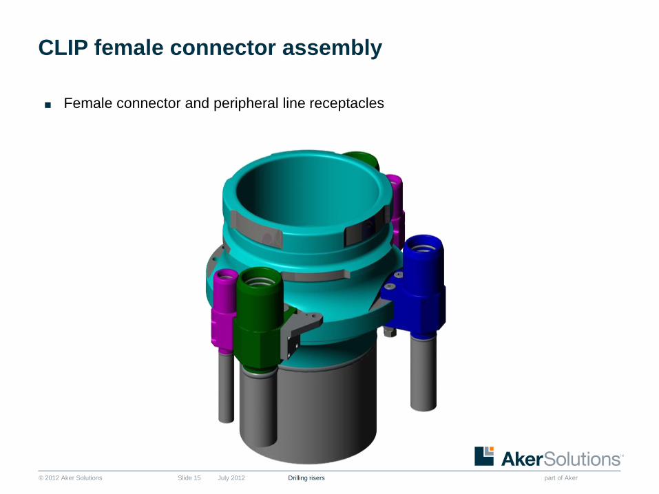
CLIP female connector assembly
July 2012 Drilling risersSlide 15
■ Female connector and peripheral line receptacles
© 2012 Aker Solutions part of Aker
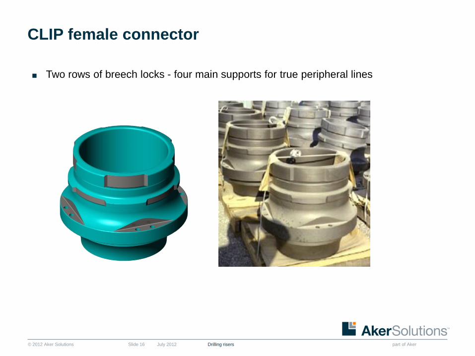
CLIP female connector
July 2012 Drilling risersSlide 16
■ Two rows of breech locks - four main supports for true peripheral lines

© 2012 Aker Solutions part of Aker
CLIP connector locking ring
July 2012 Drilling risersSlide 17
Location for index block
Rotational hole for locking
Hole for sealcutting
and replacement
Lubrication hole

© 2012 Aker Solutions part of Aker
CLIP riser make up
July 2012 Drilling risersSlide 18

© 2012 Aker Solutions part of Aker
Cross section – CLIP connector assembly
July 2012 Drilling risersSlide 19
■ Description
■ Connector is a “bayonet” type
■ Composed of 3 forged elements
■ Locking on 360º by two rows
of lugs
■ No pre-load required to
achieve full capacity
■ Main advantages
■ Fast make-up/break-out
■ Robust
■ Safe & Reliable operation

© 2012 Aker Solutions part of Aker
Peripheral lines
July 2012 Drilling risersSlide 20
■ Peripheral lines are fitted with replaceable pins
■ Pins can be replaced in the field with no need for welding

© 2012 Aker Solutions part of Aker
Replacing peripheral lines
July 2012 Drilling risersSlide 21

© 2012 Aker Solutions part of Aker
Unlocking and locking
July 2012 Drilling risersSlide 22

© 2012 Aker Solutions part of Aker
Index
July 2012 Drilling risersSlide 23
1. Introduction and background
2. General characteristics of the CLIP riser
3. The function of the CLIP connector
4. Marine riser tools, special joints and other components
5. CLIP riser in operation
6. Manufacturing of CLIP risers – where and how
7. Previous and current projects and deliveries
8. Financial impact
9. Summary

© 2012 Aker Solutions part of Aker
Flex joints
July 2012Slide 24
■ Lower flex joints are used to allow
angular misalignment between the
riser and the BOP stack, thereby
reducing the bending moment on
the riser.
■ Upper flex joints are used at the top
of the riser to allow for the motion of
the rig.
■ Intermediate flex joints can be
installed at an intermediate level in
the riser string below the telescopic
joint to reduce stresses in the riser.Upper Flex JointLower Flex Joint
Drilling risers
© 2012 Aker Solutions part of Aker
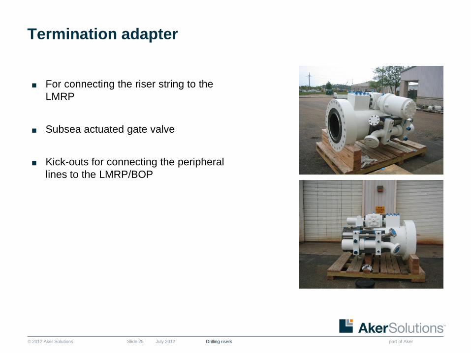
Termination adapter
July 2012 Drilling risersSlide 25
■ For connecting the riser string to the
LMRP
■ Subsea actuated gate valve
■ Kick-outs for connecting the peripheral
lines to the LMRP/BOP

© 2012 Aker Solutions part of Aker
Soft hangoff joint
July 2012 Drilling risersSlide 26
■ Used to hang off the riser string in the tension
ring when environmental conditions exceed the
limits for safe operation
■ Roller bearing to allow lateral movement of the
vessel

© 2012 Aker Solutions part of Aker
Telescopic joint
July 2012 Drilling risersSlide 27
■ Compensate for the vertical displacement of the vessel.
■ Bearing system to permit rotation of the vessel around the riser.
■ Configured with an outer and inner barrel. The outer barrel is connected to the drilling
riser, while the inner barrel is connected to the drilling vessel.
■ Collet connector assembly, to permit interlocking the Inner and outer barrels during
running and retrieval.
■ Goosenecks for terminating the peripheral lines to the rig auxiliary hoses.

© 2012 Aker Solutions part of Aker
Telescopic joint
Drilling risers
Roller
Bearing and
Bearing
Housing
Outer Barrel
Inner Barrel with
Female CLIP
Connector
Male CLIP
Connector
Assembly c/w
Guide Plate
Lifting Lug
Collet
Connector
Triple
Packer
© 2012 Aker Solutions part of Aker
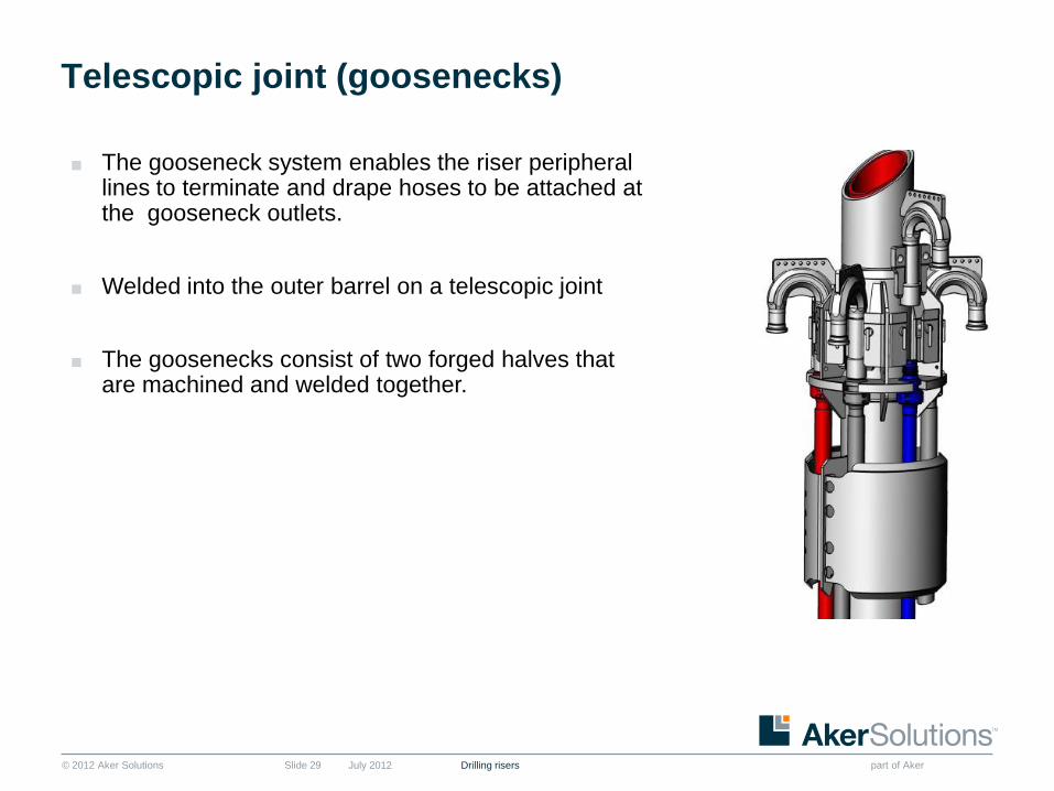
Telescopic joint (goosenecks)
July 2012 Drilling risersSlide 29
■ The gooseneck system enables the riser peripheral lines to terminate and drape hoses to be attached at the gooseneck outlets.
■ Welded into the outer barrel on a telescopic joint
■ The goosenecks consist of two forged halves that are machined and welded together.

© 2012 Aker Solutions part of Aker
Tension ring
July 2012 Drilling risersSlide 30
■ The riser tension ring is attached
to the tiser telescopic joint
■ Provides the structural interface
between the rig tensioner system
and the marine riser
■ The tensile load to support the
riser is transmitted from the rig
tensioners through the tension
ring to the outer barrel of the
telescopic joint
■ The tension ring come as solid,
hinged or split

© 2012 Aker Solutions part of Aker
Tension ring with tensioner
July 2012 Drilling risersSlide 31

© 2012 Aker Solutions part of Aker
Spacer joint
July 2012 Drilling risersSlide 32
■ Used to bridge the distance between the telescopic joint and diverter and allow for
correct space out of the telescopic joint

© 2012 Aker Solutions part of Aker
Fill-up valve
July 2012 Drilling risersSlide 33
■ Allows the Riser to fill with water to prevent the collapse of the riser string due to
pressure differences by sea water pressing on the exterior of the riser string if drilling
mud exits the riser during operation.

© 2012 Aker Solutions part of Aker
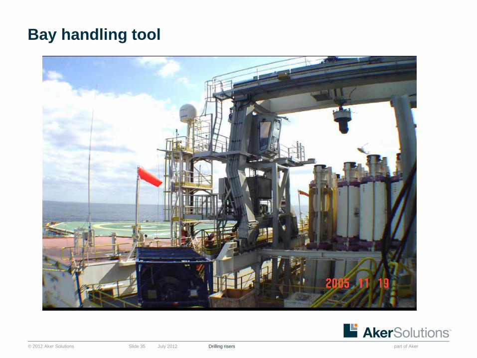
Bay handling tool
July 2012 Drilling risersSlide 34
■ Moves riser joints in and out of the riser
bay vertical storage area
■ Is designed to hold the load of one riser
joint at a time in vertical position only
■ Locks onto the lower set of lugs of the
CLIP female connector
■ Remotely operated by the crane
operator
© 2012 Aker Solutions part of Aker
Bay handling tool
July 2012 Drilling risersSlide 35

© 2012 Aker Solutions part of Aker
Test tool
July 2012 Drilling risersSlide 36
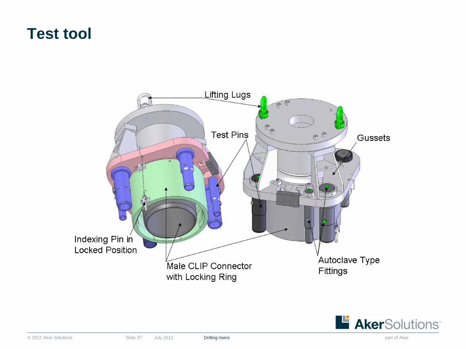
Peripheral line seals are tested as the
riser joints are made up during tripping of
the riser
The peripheral lines boxes and pin
connections must be tested when
tripping the riser to insure pressure
integrity of the lines
© 2012 Aker Solutions part of Aker
Test tool
July 2012 Drilling risersSlide 37

© 2012 Aker Solutions part of Aker
Test tool on LMRP
July 2012 Drilling risersSlide 38

© 2012 Aker Solutions part of Aker
Spider, gimbal and load plate
July 2012 Drilling risersSlide 39
Spider consists of 4 hydraulic rams
that will support and hang-off the
riser string.
Gimbal has 6 elastomeric bearings
that absorbs the loads and are able
to withstand 6 degrees movement.
Load Plate transfers the load from
the Riser/Spider/Gimbal to the rotary
table

© 2012 Aker Solutions part of Aker
Spider with rams extended
July 2012 Drilling risersSlide 40

© 2012 Aker Solutions part of Aker
Spider and gimbal
July 2012 Drilling risersSlide 41

© 2012 Aker Solutions part of Aker
Landed in spider
July 2012 Drilling risersSlide 42
© 2012 Aker Solutions part of Aker
Hydraulic and manual running tools
July 2012 Drilling risersSlide 43
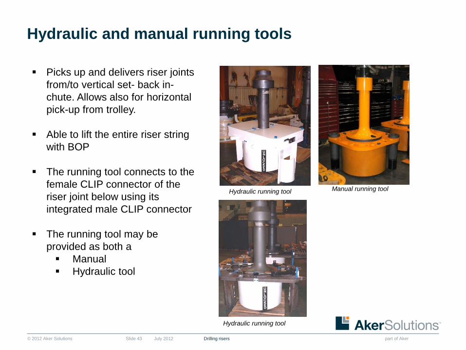
Picks up and delivers riser joints
from/to vertical set- back in-
chute. Allows also for horizontal
pick-up from trolley.
Able to lift the entire riser string
with BOP
The running tool connects to the
female CLIP connector of the
riser joint below using its
integrated male CLIP connector
The running tool may be
provided as both a
Manual
Hydraulic tool
Hydraulic running tool
Hydraulic running tool
Manual running tool

© 2012 Aker Solutions part of Aker
Index
July 2012 Drilling risersSlide 44
1. Introduction & Background
2. General characteristics of the CLIP Riser
3. The function of the CLIP connector
4. Marine Riser Tools, Special Joints and other Components
5. CLIP Riser in operation
6. Manufacturing of CLIP risers – where & how
7. Previous and Current Projects and Deliveries
8. Financial impact
9. Summary

© 2012 Aker Solutions part of Aker
Horizontally stacked
July 2012 Drilling risersSlide 45

© 2012 Aker Solutions part of Aker
Stored vertically - box up
July 2012 Drilling risersSlide 46

© 2012 Aker Solutions part of Aker
Being delivered to the rig floor – in chute
July 2012 Drilling risersSlide 47

© 2012 Aker Solutions part of Aker
Being delivered to rig floor
July 2012 Drilling risersSlide 48

© 2012 Aker Solutions part of Aker
Running CLIP riser
July 2012 Drilling risersSlide 49
© 2012 Aker Solutions part of Aker
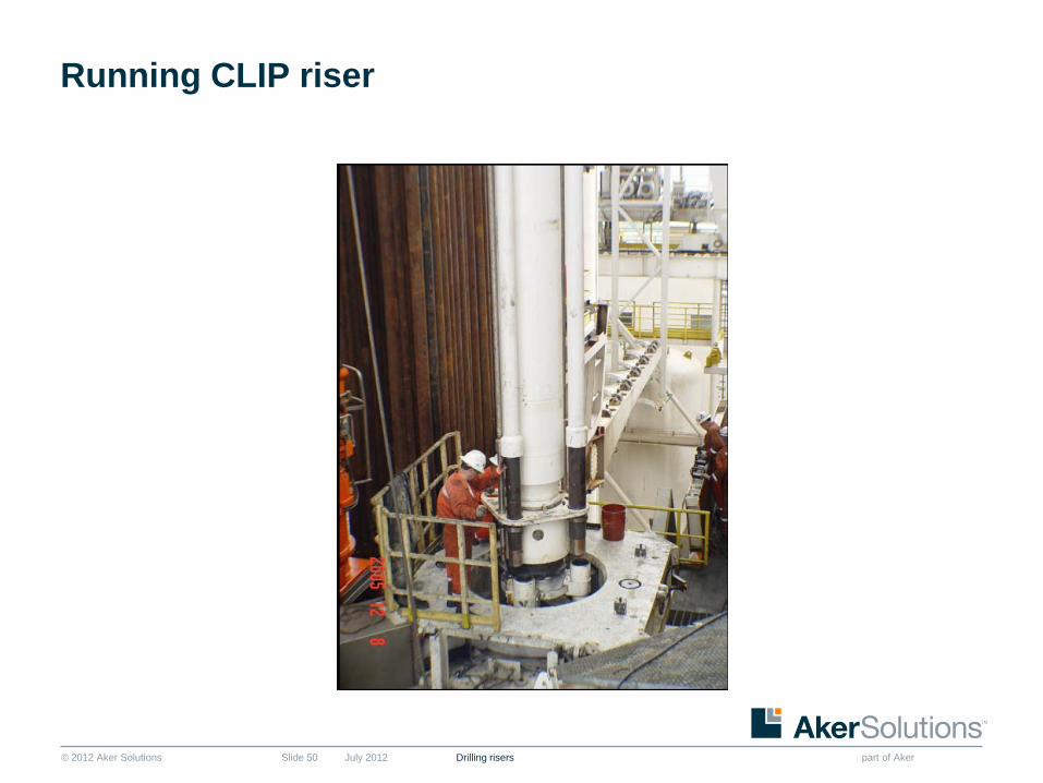
Running CLIP riser
July 2012 Drilling risersSlide 50

© 2012 Aker Solutions part of Aker
Locking the connectors
July 2012 Drilling risersSlide 51
© 2012 Aker Solutions part of Aker
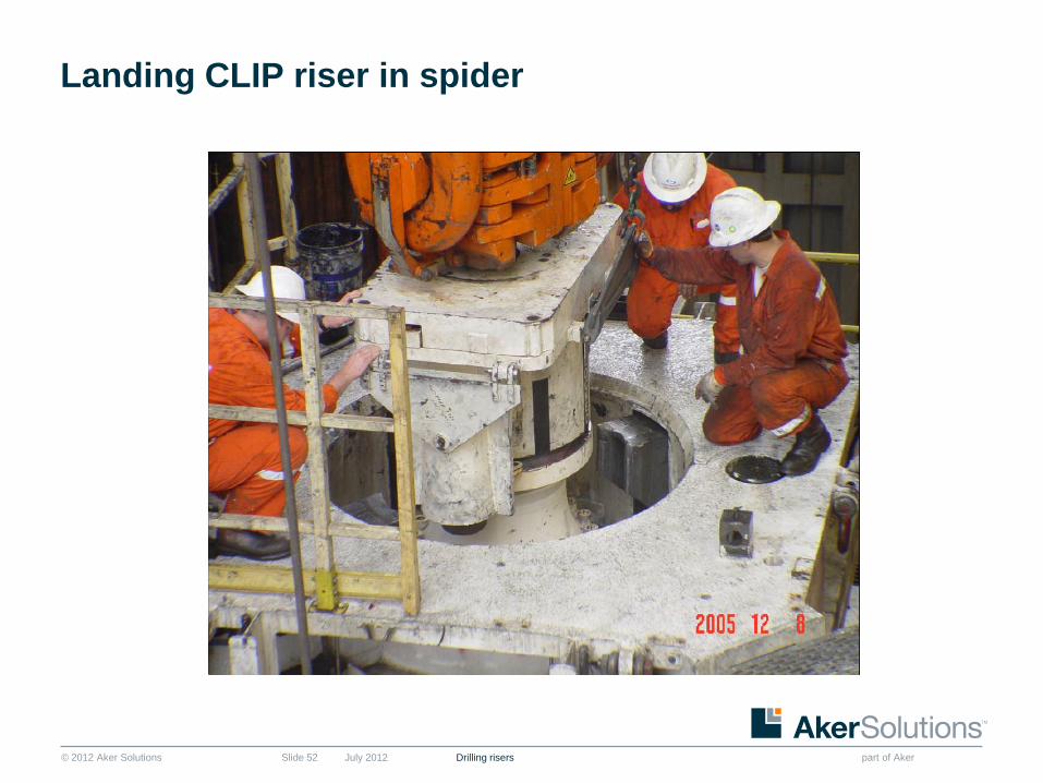
Landing CLIP riser in spider
July 2012 Drilling risersSlide 52

© 2012 Aker Solutions part of Aker
part of Aker

© 2012 Aker Solutions part of Aker
Index
July 2012 Drilling risersSlide 54
1. Introduction and background
2. General characteristics of the CLIP riser
3. The function of the CLIP connector
4. Marine riser tools, special joints and other components
5. CLIP riser in operation
6. Manufacturing of CLIP risers – where and how
7. Previous and current Projects and deliveries
8. Financial impact
9. Summary

© 2012 Aker Solutions part of Aker
Manufacturing and service locations
July 2012 Drilling risersSlide 55
Port Klang,
Malaysia
Verdal,
Norway
Rio Das Ostras,
Brazil
Mobile, AL
USA

© 2012 Aker Solutions part of Aker
High Tech Manufacturing Centre
Port Klang Free Zone – Pulau Indah 2005
July 2012 Drilling risersSlide 56

© 2011 Aker Solutions
part of Aker
High Tech Manufacturing Centre
Port Klang Free Zone – Pulau Indah 2010
Drilling Risers
Fabrication
Controls
Trees
Office Building
Subsea Structures
Process Packages
Drilling Risers
Subsea
Control
Module
Blasting &
Paint
Office Building
Machining
Warehouse
150,000 square meters land
37,000 square meters under roof
Trees
Machining
July 2012 Drilling risers

© 2012 Aker Solutions part of Aker
Plant - Rio das Ostras 2003
July 2012 Drilling risersSlide 58
© 2012 Aker Solutions part of Aker
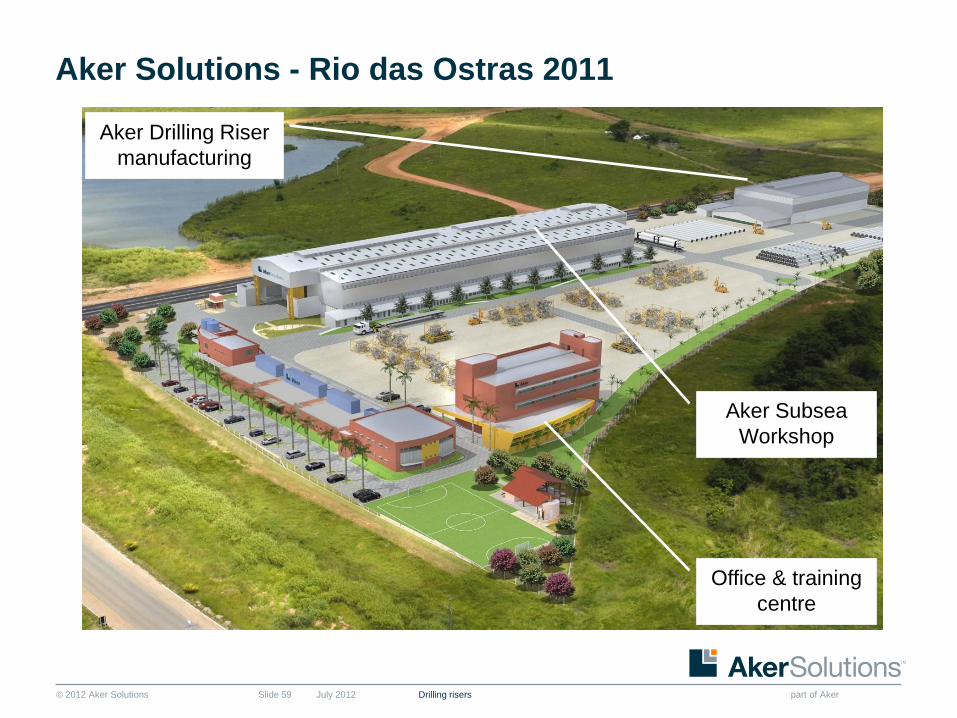
Aker Solutions - Rio das Ostras 2011
July 2012 Drilling risersSlide 59
Office & training
centre
Aker Subsea
Workshop
Aker Drilling Riser
manufacturing

© 2012 Aker Solutions part of Aker
Manufacturing – CLIP riser joint
July 2012 Drilling risersSlide 60
Cutting Bevelling Pre Heating Welding
NDT- Dimensional NDT - Ultrasonic NDT - Hardness NDT–Magnetic Particles
Heat Treatment Pressure Test Painting Assembly
© 2012 Aker Solutions part of Aker
Index
July 2012 Drilling risersSlide 61
1. Introduction and background
2. General characteristics of the CLIP riser
3. The function of the CLIP connector
4. Marine riser tools, special joints and other components
5. CLIP riser in operation
6. Manufacturing of CLIP risers – where and how
7. Previous and current projects and deliveries
8. Financial impact
9. Summary

© 2012 Aker Solutions part of Aker
20 CLIP risers in operation offshore
July 2012 Drilling risersSlide 62
■ Sonat
■ Discoverer Seven Seas* 6000 ft 1981
■ Pride International
■ Pride Africa 6300 ft 1999
■ Pride Angola 6300 ft 1999
■ Pride Replacement Riser 2300 ft 1999
■ Pride Spare 6300 ft 2000
■ Transocean/GlobalSantaFe
■ Development Driller I 7500 ft 2002
■ Development Driller II 7500 ft 2002
■ GlobalSantaFe Spare 7500 ft 2003
■ Development Driller III 7500 ft 2009
■ Luanda 7,500 ft 2010
■ TMT
■ TMT1 Platinum Explorer 7,500 ft 2010
* 18 5/8’’ Riser. No longer in service

© 2012 Aker Solutions part of Aker
20 CLIP risers in operation offshore cont’d
July 2012 Drilling risersSlide 63
■ Aker Drilling
■ Aker Barents 2500 ft 2009
■ Aker Spitsbergen 2500 ft 2009
■ Aker Extension 5000 ft 2010
■ Maersk
■ Developer 10,000 ft 2009
■ Discoverer 10,000 ft 2010
■ Sevan
■ Driller 10,000 ft 2010
■ Quieroz Galvão
■ Olinda Star 2500 ft 2009
■ Gold Star 6600 ft 2010
■ Lone Star 8,000 ft 2010
■ Alpha Star 8,000 ft 2010
■ CNOOC
■ Mandarin Driller 10,000 ft 2010

© 2012 Aker Solutions part of Aker
CLIP risers on order
July 2012 Drilling risersSlide 64
■ TMT
■ TMT 2 7,500 ft 2011
■ TMT 3 7,500 ft 2011
■ TMT 1 Extension 2,500 ft 2011
■ Grupo R
■ Grupo R 2 7,500 ft 2011
■ Grupo R1 Extension 2,500 ft 2011
■ Atwood Oceanics
■ Osprey 6,600 ft 2011
■ Atwood 11 10,000 ft 2011
■ Sevan
■ Brazil 8,000 ft 2012
© 2012 Aker Solutions part of Aker
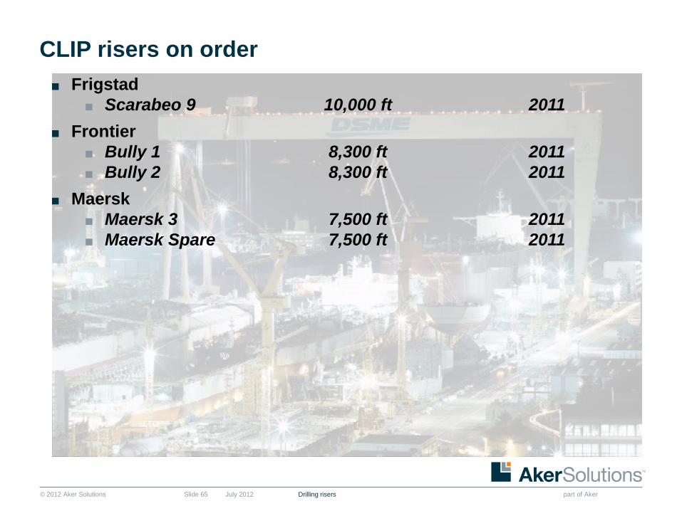
CLIP risers on order
July 2012 Drilling risersSlide 65
■ Frigstad
■ Scarabeo 9 10,000 ft 2011
■ Frontier
■ Bully 1 8,300 ft 2011
■ Bully 2 8,300 ft 2011
■ Maersk
■ Maersk 3 7,500 ft 2011
■ Maersk Spare 7,500 ft 2011
© 2012 Aker Solutions part of Aker
Index
July 2012 Drilling risersSlide 66
1. Introduction and background
2. General characteristics of the CLIP riser
3. The function of the CLIP connector
4. Marine riser tools, special joints and other components
5. CLIP riser in operation
6. Manufacturing of CLIP risers – where and how
7. Previous and current projects and deliveries
8. Financial impact
9. Summary

© 2012 Aker Solutions part of Aker
Time saving
July 2012 Drilling risersSlide 67
The time saved in operation has a significant financial impact
CLIP breechlock
Make-up tool (steel bar)
Flanged riser
Hydraulic torque wrench
versus
© 2012 Aker Solutions part of Aker
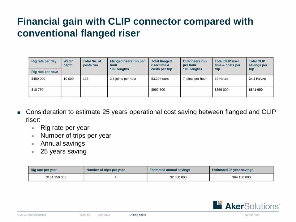
Financial gain with CLIP connector compared with
conventional flanged riser
July 2012 Drilling risersSlide 68
■ Consideration to estimate 25 years operational cost saving between flanged and CLIP
riser:
Rig rate per year
Number of trips per year
Annual savings
25 years saving
Rig rate per day Water
depth
Total No. of
joints run
Flanged risers run per
hour
100’ lengths
Total flanged
riser time &
costs per trip
CLIP risers run
per hour
100’ lengths
Total CLIP riser
time & costs per
trip
Total CLIP
savings per
tripRig rate per hour
$450 000 10 000 133 2.5 joints per hour 53.20 hours 7 joints per hour 19 Hours 34.2 Hours
$18 750 $997 500 $356 000 $641 000
Rig rate per year Number of trips per year Estimated annual savings Estimated 25 year savings
$164 250 000 4 $2 560 000 $64 100 000

© 2012 Aker Solutions part of Aker
Index
July 2012 Drilling risersSlide 69
1. Introduction and background
2. General characteristics of the CLIP riser
3. The function of the CLIP connector
4. Marine riser tools, special joints and other components
5. CLIP riser in operation
6. Manufacturing of CLIP risers – where and how
7. Previous and current projects and deliveries
8. Financial impact
9. Summary

© 2012 Aker Solutions part of Aker
Summary in brief
July 2012 Drilling risersSlide 70
■ This breech locking mechanism is designed to offer the operators a means of saving
substantial make up time, as compared to a conventional flanged-type riser joint, with
total safety when drilling in deep waters
■ Average make-up time to make up the pin/box connection of the CLIP riser is 11
seconds. The two connectors are stabbed together and the locking ring is rotated 45
degrees
■ Most secure connection: fully opened or closed positions only
■ Key safety feature: minimizes dropped object as no bolts are used to make up theconnection between the two joints
■ Field experience has shown that six to eight joints can be run per hour
■ No threading, bolting or preloading
■ Easy stabbing even with misalignment
Operational time savings and safety enables financial benefits
© 2012 Aker Solutions part of AkerJuly 2012 Drilling risersSlide 71
Thank you very much for
your attention

© 2012 Aker Solutions part of Aker
Copyright and disclaimer
CopyrightCopyright of all published material including photographs, drawings and images in this document remains vested in Aker Solutions and
third party contributors as appropriate. Accordingly, neither the whole nor any part of this document shall be reproduced in any form nor
used in any manner without express prior permission and applicable acknowledgements. No trademark, copyright or other notice shall
be altered or removed from any reproduction.
DisclaimerThis Presentation includes and is based, inter alia, on forward-looking information and statements that are subject to risks and
uncertainties that could cause actual results to differ. These statements and this Presentation are based on current expectations,
estimates and projections about global economic conditions, the economic conditions of the regions and industries that are major
markets for Aker Solutions ASA and Aker Solutions ASA’s (including subsidiaries and affiliates) lines of business. These expectations,
estimates and projections are generally identifiable by statements containing words such as “expects”, “believes”, “estimates” or similar
expressions. Important factors that could cause actual results to differ materially from those expectations include, among others,
economic and market conditions in the geographic areas and industries that are or will be major markets for Aker Solutions’ businesses,
oil prices, market acceptance of new products and services, changes in governmental regulations, interest rates, fluctuations in currency
exchange rates and such other factors as may be discussed from time to time in the Presentation. Although Aker Solutions ASA believes
that its expectations and the Presentation are based upon reasonable assumptions, it can give no assurance that those expectations will
be achieved or that the actual results will be as set out in the Presentation. Aker Solutions ASA is making no representation or warranty,
expressed or implied, as to the accuracy, reliability or completeness of the Presentation, and neither Aker Solutions ASA nor any of its
directors, officers or employees will have any liability to you or any other persons resulting from your use.
Aker Solutions consists of many legally independent entities, constituting their own separate identities. Aker Solutions is used as the
common brand or trade mark for most of these entities. In this presentation we may sometimes use “Aker Solutions”, “we” or “us” when
we refer to Aker Solutions companies in general or where no useful purpose is served by identifying any particular Aker Solutions
company.
Drilling risersJuly 2012Slide 72