Embed Size (px)
Citation preview
DEEPWATER, HIGH-PRESSURE AND ,MULTIDIAMETER PIPELINES
A CHALLENGING IN-LINE INSPECTION PROJECT
PPSA ONE-DAY Seminar19. November 2008
M liff H t l Ab dMarcliffe Hotel Aberdeen
Rosen Research and Technology CenterHubert Lindner17-Nov-08
Contents
1. The 14”/18” Multi-Diameter Challenge2. Project Procedure3 Tool Design3. Tool Design4. Test Loop Construction 5 Testing5. Testing6. Contingency Plan7. On-Site operationsp8. Summary
Copyright © ROSEN Group 2008 - Copy prepared for PPSA 14“/18“ Deepwater Project | H. Lindner | 13-Nov-08
1. The 14"x18" Multi-Diameter Challenge
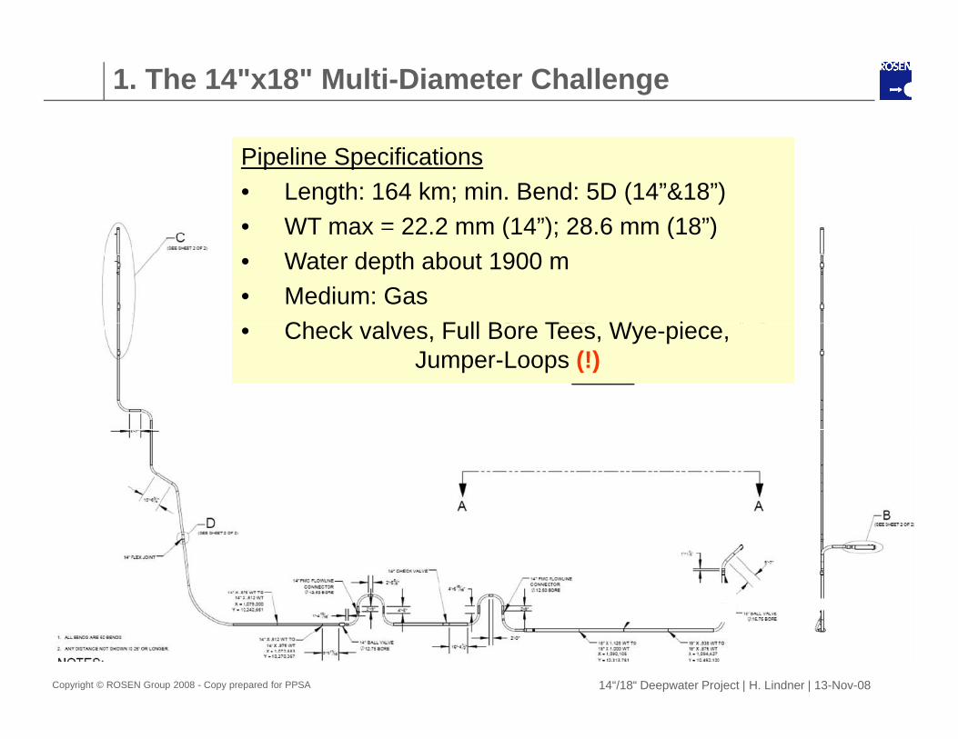
Pipeline Specifications• Length: 164 km; min. Bend: 5D (14”&18”)• WT max = 22 2 mm (14”); 28 6 mm (18”)WT max 22.2 mm (14 ); 28.6 mm (18 )• Water depth about 1900 m• Medium: Gas
Ch k l F ll B T W i• Check valves, Full Bore Tees, Wye-piece,Jumper-Loops (!)
Copyright © ROSEN Group 2008 - Copy prepared for PPSA 14“/18“ Deepwater Project | H. Lindner | 13-Nov-08
1. The 14"x18" Multi-Diameter Challenge
Challenging Requirements:Challenging Requirements:- Internal Diameter Ratio: 300 mm/418 mm = 0.717- That means an operating range of about 28%p g g- High Pressure Design: 300 bar- Passage of Installations - Particular wye-piece passage
Copyright © ROSEN Group 2008 - Copy prepared for PPSA 14“/18“ Deepwater Project | H. Lindner | 13-Nov-08
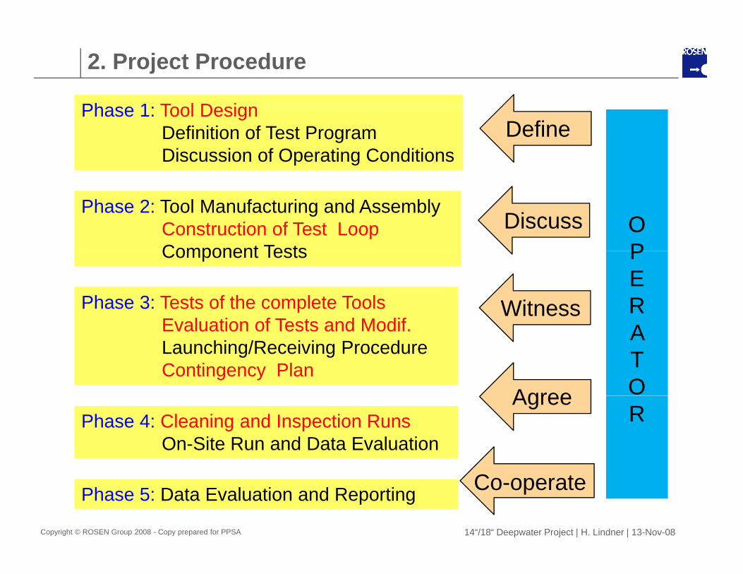
2. Project Procedure
Ph 1 T l D iPh 1 T l D iPhase 1: Tool Design Definition of Test Program Discussion of Operating Conditions
Phase 1: Tool Design Definition of Test Program Discussion of Operating Conditions
Define
Phase 2: Tool Manufacturing and Assembly Construction of Test Loop Component Tests
Phase 2: Tool Manufacturing and Assembly Construction of Test Loop Component Tests
O PO P
DiscussComponent TestsComponent Tests
Phase 3: Tests of the complete Tools Evaluation of Tests and Modif
Phase 3: Tests of the complete Tools Evaluation of Tests and Modif
P E R
P E R Witness
Evaluation of Tests and Modif. Launching/Receiving Procedure Contingency Plan
Evaluation of Tests and Modif. Launching/Receiving Procedure Contingency Plan
A T O
A T O Agree
Phase 4: Cleaning and Inspection Runs On-Site Run and Data Evaluation
Phase 4: Cleaning and Inspection Runs On-Site Run and Data Evaluation
R R Agree
Copyright © ROSEN Group 2008 - Copy prepared for PPSA 14“/18“ Deepwater Project | H. Lindner | 13-Nov-08
Phase 5: Data Evaluation and ReportingPhase 5: Data Evaluation and Reporting Co-operate
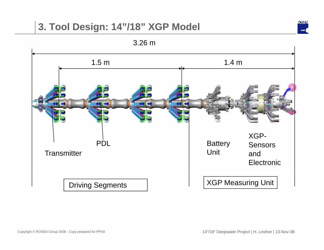
3. Tool Design: 14”/18” XGP Model3.26 m
1.5 m 1.4 m
PDL B ttXGP-
TransmitterPDL Battery
UnitSensors and Electronic
Driving Segments XGP Measuring Unit
Copyright © ROSEN Group 2008 - Copy prepared for PPSA 14“/18“ Deepwater Project | H. Lindner | 13-Nov-08
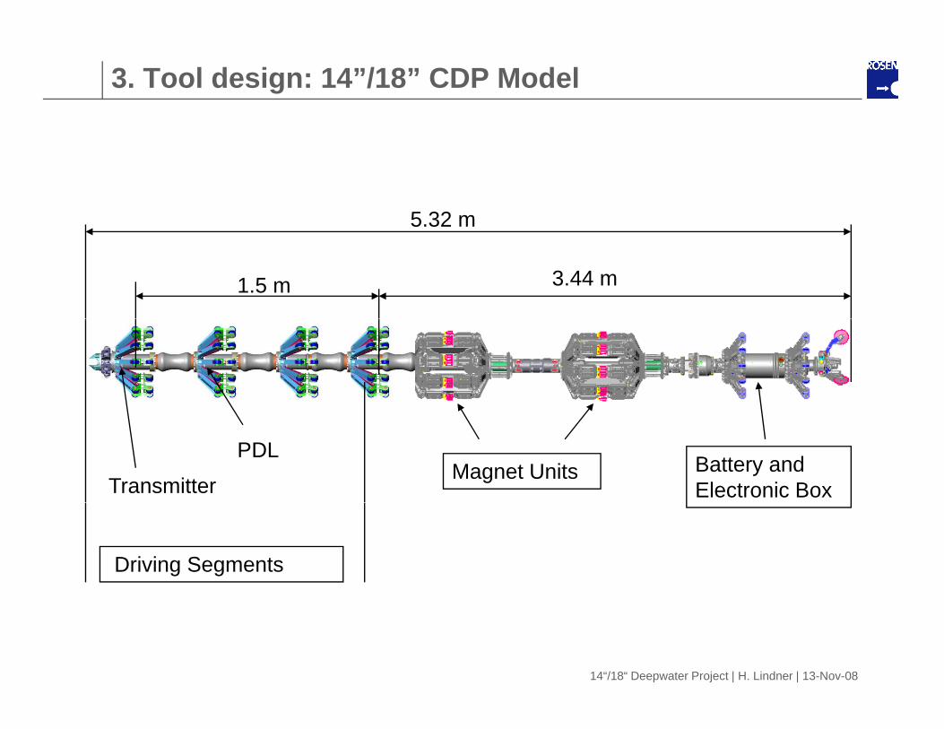
3. Tool design: 14”/18” CDP Model
5.32 m5 3
3.44 m1.5 m
Magnet Units Battery and Electronic BoxTransmitter
PDL
Driving Segments
14“/18“ Deepwater Project | H. Lindner | 13-Nov-08
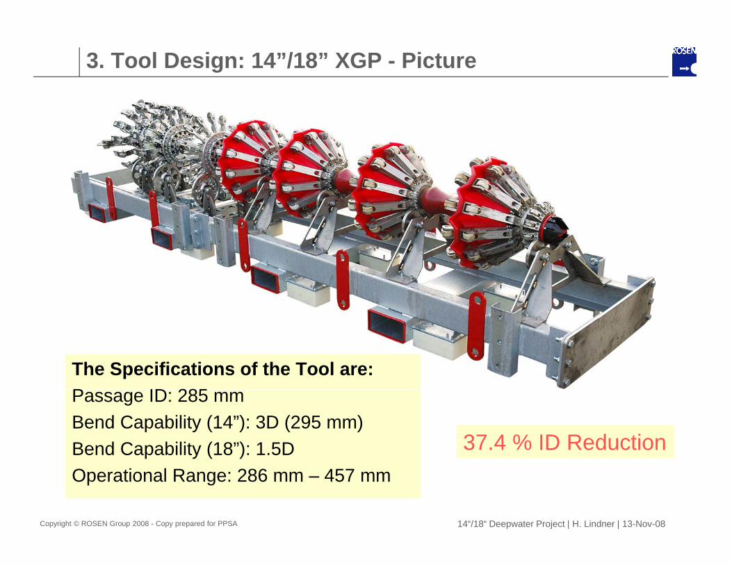
3. Tool Design: 14”/18” XGP - Picture
The Specifications of the Tool are:P ID 285Passage ID: 285 mmBend Capability (14”): 3D (295 mm)Bend Capability (18”): 1.5D 37.4 % ID Reduction
Copyright © ROSEN Group 2008 - Copy prepared for PPSA 14“/18“ Deepwater Project | H. Lindner | 13-Nov-08
Operational Range: 286 mm – 457 mm
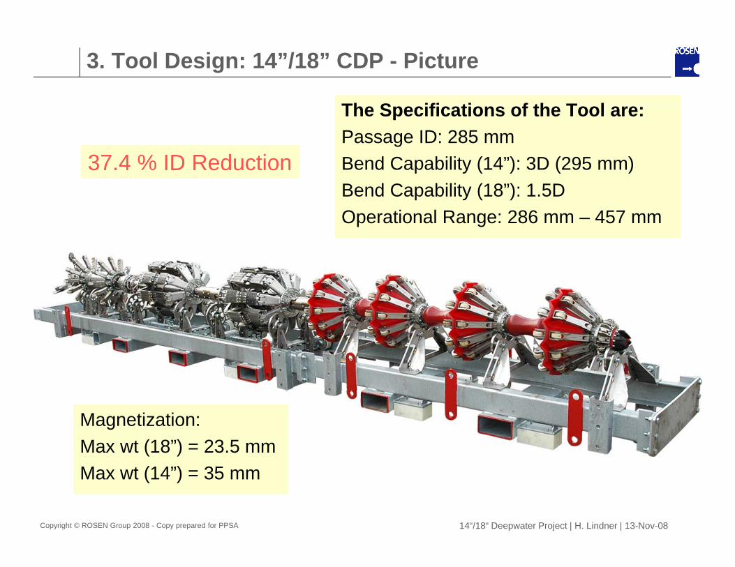
3. Tool Design: 14”/18” CDP - Picture
Th S ifi ti f th T lThe Specifications of the Tool are:Passage ID: 285 mmBend Capability (14”): 3D (295 mm)37.4 % ID ReductionBend Capability (18”): 1.5DOperational Range: 286 mm – 457 mm
Magnetization:Max wt (18”) = 23.5 mm
Copyright © ROSEN Group 2008 - Copy prepared for PPSA 14“/18“ Deepwater Project | H. Lindner | 13-Nov-08
Max wt (14”) = 35 mm
4. Test Loop Construction
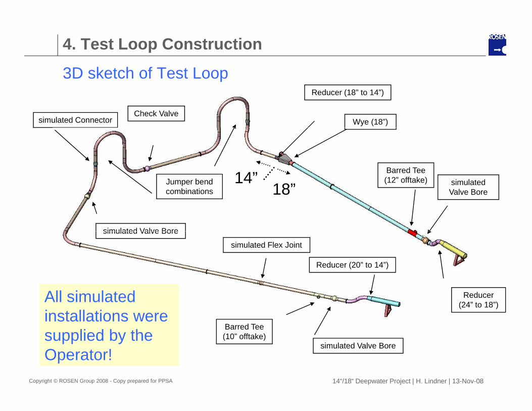
3D sketch of Test Loop3D sketch of Test Loop
Check Valve
Reducer (18” to 14”)
Wye (18”)simulated Connector
Barred Tee (12” offtake) i l t d14”J b d
simulated Valve Bore
(12 offtake) simulated Valve Bore18”
14Jumper bend combinations
simulated Valve Bore
simulated Flex Joint
Reducer (20” to 14”)
Barred Tee (10” offtake)
Reducer (24” to 18”)
All simulated installations were supplied by the
Copyright © ROSEN Group 2008 - Copy prepared for PPSA 14“/18“ Deepwater Project | H. Lindner | 13-Nov-08
simulated Valve Bore(10 offtake)supplied by the
Operator!
4. Test Loop Construction
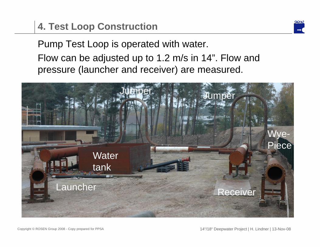
Pump Test Loop is operated with waterPump Test Loop is operated with water.Flow can be adjusted up to 1.2 m/s in 14”. Flow and pressure (launcher and receiver) are measured.
Jumper Jumper
Wye-Piece
Water tank
Launcher Receiver
tank
Copyright © ROSEN Group 2008 - Copy prepared for PPSA 14“/18“ Deepwater Project | H. Lindner | 13-Nov-08
5. Testing
The test phase was divided in three basic segments:The test phase was divided in three basic segments:1. Basic Components tests like:
Pressure testing of basic components (e.g. Sensors) Sealing and over flip capabilities of the cup Durability test of support wheels
2 Tool Segments tests like:2. Tool Segments tests like:Pull tests of the Driving Unit (condition, pulling Load) Pump test of the Driving Unit (pressure, condition) P t t f l t i t tPressure test of electronic compartments
3. Tests in the 14”/18” test loop: (shown in the following) Pump velocity about 0.7 m/s in 18” and 1.1 m/s in 14”.Pump velocity about 0.7 m/s in 18 and 1.1 m/s in 14 . On board pressure and acceleration measurement (PDL).
Copyright © ROSEN Group 2008 - Copy prepared for PPSA 14“/18“ Deepwater Project | H. Lindner | 13-Nov-08

5. PDL Data of 1. XGP Pump Tests in 14”/18” LoopSynchronized Analysis of PDL DataSy c o ed a ys s o a a
Differential Pressure9 bar pressure peak!
14” pipe 1.2 bar
18” pipe2 bar
Tool InclinationJumper 1
Launching ReceivingJumper 2
Copyright © ROSEN Group 2008 - Copy prepared for PPSA 14“/18“ Deepwater Project | H. Lindner | 13-Nov-08
Receiving
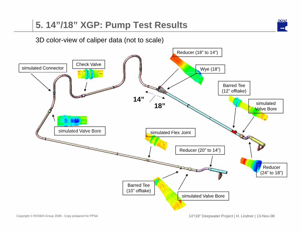
5. 14”/18” XGP: Pump Test Results3D color-view of caliper data (not to scale)p ( )
Check Valve
Reducer (18” to 14”)
Wye (18”)simulated Connector
Barred Tee (12” offtake)
i l t d14”
simulated Valve Bore i l t d Fl J i t
simulated Valve Bore18”
simulated Valve Bore simulated Flex Joint
Reducer (20” to 14”)
Barred Tee (10” offtake)
Reducer (24” to 18”)
Copyright © ROSEN Group 2008 - Copy prepared for PPSA 14“/18“ Deepwater Project | H. Lindner | 13-Nov-08
simulated Valve Bore(10 offtake)
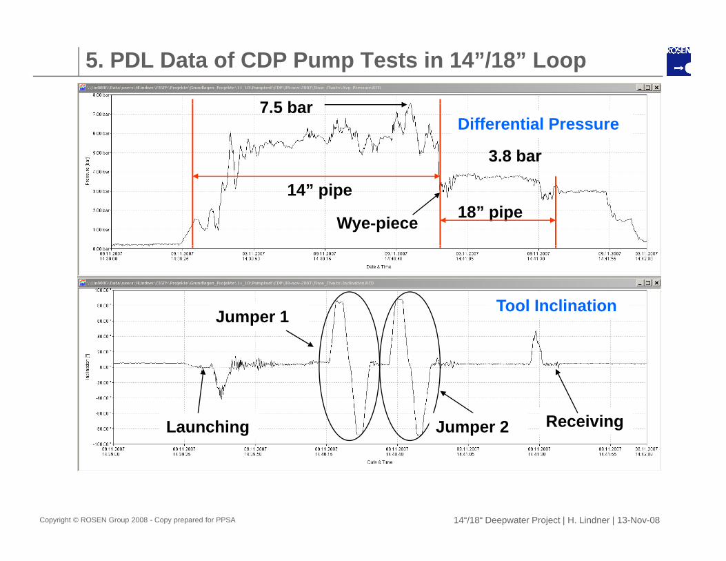
5. PDL Data of CDP Pump Tests in 14”/18” Loop
7 5 bDifferential Pressure
7.5 bar
3.8 bar
Wye-piece
14” pipe18” pipe
Tool InclinationJumper 1Jumper 1
Launching ReceivingJumper 2
Copyright © ROSEN Group 2008 - Copy prepared for PPSA 14“/18“ Deepwater Project | H. Lindner | 13-Nov-08

6. Contingency Plan
Di i d d fi iti f tiDiscussion and definition of a contingency plan between ROSEN and the Operator!
-Scenarios-SCADA measures-Communication-Decision Points-Possible Actions
Copyright © ROSEN Group 2008 - Copy prepared for PPSA 14“/18“ Deepwater Project | H. Lindner | 13-Nov-08
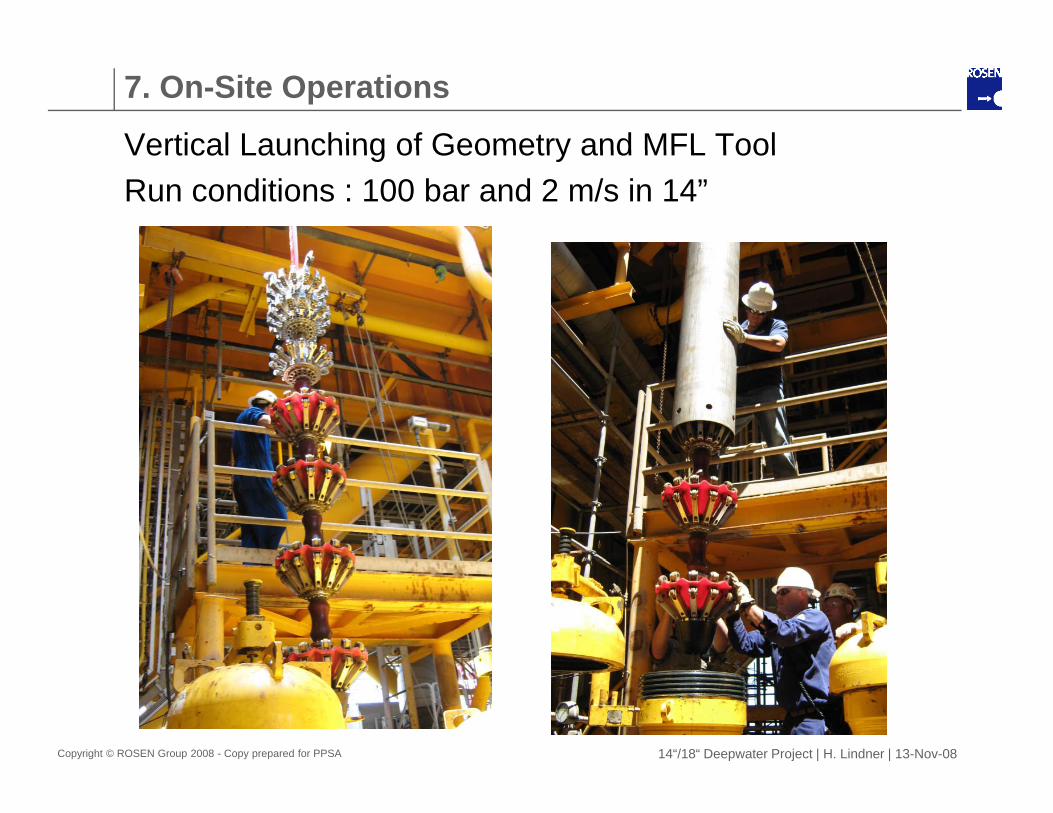
7. On-Site Operations
Vertical Launching of Geometry and MFL ToolVertical Launching of Geometry and MFL ToolRun conditions : 100 bar and 2 m/s in 14”
Copyright © ROSEN Group 2008 - Copy prepared for PPSA 14“/18“ Deepwater Project | H. Lindner | 13-Nov-08
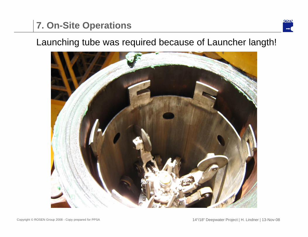
7. On-Site Operations
Launching tube was required because of Launcher langth!Launching tube was required because of Launcher langth!
Copyright © ROSEN Group 2008 - Copy prepared for PPSA 14“/18“ Deepwater Project | H. Lindner | 13-Nov-08
7. On-Site Operations
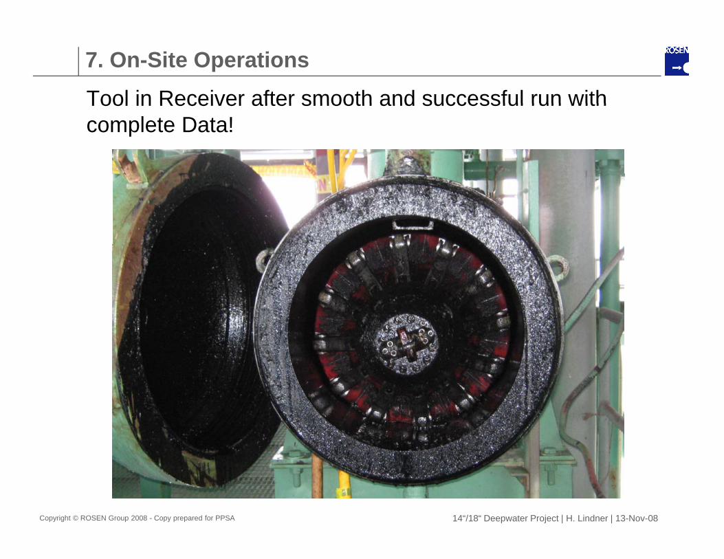
Tool in Receiver after smooth and successful run withTool in Receiver after smooth and successful run with complete Data!
Copyright © ROSEN Group 2008 - Copy prepared for PPSA 14“/18“ Deepwater Project | H. Lindner | 13-Nov-08
7. On-Site Operations
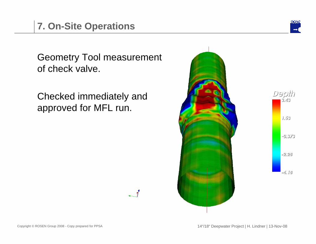
Geometry Tool measurement of check valve.
Checked immediately and approved for MFL runapproved for MFL run.
Copyright © ROSEN Group 2008 - Copy prepared for PPSA 14“/18“ Deepwater Project | H. Lindner | 13-Nov-08
8. Summary
fA project for a challenging Multi-Diameter Pipeline was conducted in close co-operation between ROSEN and the Operator.p
Cleaning and Inspection Tools (Geometry and MFL) were developed and built as well as a full size Test Loop containing simulations of all relevant Installations. A wide range of tests have been performed.g p
The runs were successfully conducted.
The Operator and ROSEN have defined several procedures including a Contingency Plan
Copyright © ROSEN Group 2008 - Copy prepared for PPSA
procedures including a Contingency Plan.
14“/18“ Deepwater Project | H. Lindner | 13-Nov-08

Thank you for joining this presentation.