Embed Size (px)
Citation preview
Deepwater Well Design and Construction
API RECOMMENDED PRACTICE 96FIRST EDITION, MARCH 2013
Copyright American Petroleum Institute Provided by IHS under license with API Licensee=Chevron Corporate Wide/1000001100
Not for Resale, 07/30/2013 13:49:03 MDTNo reproduction or networking permitted without license from IHS
--``,,`,````,``,`,``,,,`,,``,`-`-`,,`,,`,`,,`---
Special Notes
API publications necessarily address problems of a general nature. With respect to particular circumstances, local,state, and federal laws and regulations should be reviewed.
Neither API nor any of API's employees, subcontractors, consultants, committees, or other assignees make anywarranty or representation, either express or implied, with respect to the accuracy, completeness, or usefulness of theinformation contained herein, or assume any liability or responsibility for any use, or the results of such use, of anyinformation or process disclosed in this publication. Neither API nor any of API's employees, subcontractors,consultants, or other assignees represent that use of this publication would not infringe upon privately owned rights.
API publications may be used by anyone desiring to do so. Every effort has been made by the Institute to assure theaccuracy and reliability of the data contained in them; however, the Institute makes no representation, warranty, orguarantee in connection with this publication and hereby expressly disclaims any liability or responsibility for loss ordamage resulting from its use or for the violation of any authorities having jurisdiction with which this publication mayconflict.
API publications are published to facilitate the broad availability of proven, sound engineering and operatingpractices. These publications are not intended to obviate the need for applying sound engineering judgmentregarding when and where these publications should be utilized. The formulation and publication of API publicationsis not intended in any way to inhibit anyone from using any other practices.
Any manufacturer marking equipment or materials in conformance with the marking requirements of an API standardis solely responsible for complying with all the applicable requirements of that standard. API does not represent,warrant, or guarantee that such products do in fact conform to the applicable API standard.
Users of this Recommended Practice should not rely exclusively on the information contained in this document.Sound business, scientific, engineering, and safety judgment should be used in employing the information containedherein.
All rights reserved. No part of this work may be reproduced, translated, stored in a retrieval system, or transmitted by any means, electronic, mechanical, photocopying, recording, or otherwise, without prior written permission from the publisher. Contact the
Publisher, API Publishing Services, 1220 L Street, NW, Washington, DC 20005.
Copyright © 2013 American Petroleum Institute
Copyright American Petroleum Institute Provided by IHS under license with API Licensee=Chevron Corporate Wide/1000001100
Not for Resale, 07/30/2013 13:49:03 MDTNo reproduction or networking permitted without license from IHS
--``,,`,````,``,`,``,,,`,,``,`-`-`,,`,,`,`,,`---
Foreword
Life cycle well integrity is an important objective in the design and execution of a deepwater (DW) well program.Technical, operational, and organizational solutions are to be employed such that the risk of an unintended release offormation fluids is minimized during drilling, completion, operational, and abandonment phases of the well. Thisdocument describes established well design practices and operational procedures that engineers, well planners, andoperators consider when planning and executing a DW well project. It is not intended to prohibit the development andapplication of new technology.
The verbal forms used to express the provisions in this recommended practice are as follows:
— the term “shall” denotes a minimum requirement in order to conform to the recommended practice;
— the term “should” denotes a recommendation or that which is advised but not required in order to conform to therecommended practice;
— the term “may” is used to express permission or a provision that is optional;
— the term “can” is used to express possibility or capability.
Nothing contained in any API publication is to be construed as granting any right, by implication or otherwise, for themanufacture, sale, or use of any method, apparatus, or product covered by letters patent. Neither should anythingcontained in the publication be construed as insuring anyone against liability for infringement of letters patent.
This document was produced under API standardization procedures that ensure appropriate notification andparticipation in the developmental process and is designated as an API standard. Questions concerning theinterpretation of the content of this publication or comments and questions concerning the procedures under whichthis publication was developed should be directed in writing to the Director of Standards, American PetroleumInstitute, 1220 L Street, NW, Washington, DC 20005. Requests for permission to reproduce or translate all or any partof the material published herein should also be addressed to the director.
Generally, API standards are reviewed and revised, reaffirmed, or withdrawn at least every five years. A one-timeextension of up to two years may be added to this review cycle. Status of the publication can be ascertained from theAPI Standards Department, telephone (202) 682-8000. A catalog of API publications and materials is publishedannually by API, 1220 L Street, NW, Washington, DC 20005.
Suggested revisions are invited and should be submitted to the Standards Department, API, 1220 L Street, NW,Washington, DC 20005, [email protected].
iii
Copyright American Petroleum Institute Provided by IHS under license with API Licensee=Chevron Corporate Wide/1000001100
Not for Resale, 07/30/2013 13:49:03 MDTNo reproduction or networking permitted without license from IHS
--``,,`,````,``,`,``,,,`,,``,`-`-`,,`,,`,`,,`---

Copyright American Petroleum Institute Provided by IHS under license with API Licensee=Chevron Corporate Wide/1000001100
Not for Resale, 07/30/2013 13:49:03 MDTNo reproduction or networking permitted without license from IHS
--``,,`,````,``,`,``,,,`,,``,`-`-`,,`,,`,`,,`---
Contents
Page
1 Scope . . . . . . . . . . . . . . . . . . . . . . . . . . . . . . . . . . . . . . . . . . . . . . . . . . . . . . . . . . . . . . . . . . . . . . . . . . . . . . . . . . 1
2 Normative References. . . . . . . . . . . . . . . . . . . . . . . . . . . . . . . . . . . . . . . . . . . . . . . . . . . . . . . . . . . . . . . . . . . . . 2
3 Terms, Definitions, and Abbreviations . . . . . . . . . . . . . . . . . . . . . . . . . . . . . . . . . . . . . . . . . . . . . . . . . . . . . . . 23.1 Terms and Definitions . . . . . . . . . . . . . . . . . . . . . . . . . . . . . . . . . . . . . . . . . . . . . . . . . . . . . . . . . . . . . . . . . . . . . 23.2 Abbreviations. . . . . . . . . . . . . . . . . . . . . . . . . . . . . . . . . . . . . . . . . . . . . . . . . . . . . . . . . . . . . . . . . . . . . . . . . . . 10
4 Deepwater Rig Systems and Subsea Configurations . . . . . . . . . . . . . . . . . . . . . . . . . . . . . . . . . . . . . . . . . . 114.1 General . . . . . . . . . . . . . . . . . . . . . . . . . . . . . . . . . . . . . . . . . . . . . . . . . . . . . . . . . . . . . . . . . . . . . . . . . . . . . . . . 114.2 Rig Options . . . . . . . . . . . . . . . . . . . . . . . . . . . . . . . . . . . . . . . . . . . . . . . . . . . . . . . . . . . . . . . . . . . . . . . . . . . . 124.3 Stationkeeping System. . . . . . . . . . . . . . . . . . . . . . . . . . . . . . . . . . . . . . . . . . . . . . . . . . . . . . . . . . . . . . . . . . . 124.4 Marine Drilling Riser System . . . . . . . . . . . . . . . . . . . . . . . . . . . . . . . . . . . . . . . . . . . . . . . . . . . . . . . . . . . . . . 144.5 BOP System . . . . . . . . . . . . . . . . . . . . . . . . . . . . . . . . . . . . . . . . . . . . . . . . . . . . . . . . . . . . . . . . . . . . . . . . . . . . 144.6 BOP Control System . . . . . . . . . . . . . . . . . . . . . . . . . . . . . . . . . . . . . . . . . . . . . . . . . . . . . . . . . . . . . . . . . . . . . 164.7 Emergency Functions. . . . . . . . . . . . . . . . . . . . . . . . . . . . . . . . . . . . . . . . . . . . . . . . . . . . . . . . . . . . . . . . . . . . 184.8 Subsea Wellhead and Production Tree Configurations . . . . . . . . . . . . . . . . . . . . . . . . . . . . . . . . . . . . . . . . 204.9 Remotely Operated Vehicle Systems . . . . . . . . . . . . . . . . . . . . . . . . . . . . . . . . . . . . . . . . . . . . . . . . . . . . . . . 20
5 Well Design Considerations. . . . . . . . . . . . . . . . . . . . . . . . . . . . . . . . . . . . . . . . . . . . . . . . . . . . . . . . . . . . . . . 215.1 General . . . . . . . . . . . . . . . . . . . . . . . . . . . . . . . . . . . . . . . . . . . . . . . . . . . . . . . . . . . . . . . . . . . . . . . . . . . . . . . . 215.2 Deepwater Well Architecture . . . . . . . . . . . . . . . . . . . . . . . . . . . . . . . . . . . . . . . . . . . . . . . . . . . . . . . . . . . . . . 215.3 Barrier Philosophy . . . . . . . . . . . . . . . . . . . . . . . . . . . . . . . . . . . . . . . . . . . . . . . . . . . . . . . . . . . . . . . . . . . . . . 295.4 Load Cases Drilling and Completion Conditions . . . . . . . . . . . . . . . . . . . . . . . . . . . . . . . . . . . . . . . . . . . . . 375.5 Tubing Design . . . . . . . . . . . . . . . . . . . . . . . . . . . . . . . . . . . . . . . . . . . . . . . . . . . . . . . . . . . . . . . . . . . . . . . . . . 41
6 Special Considerations for Drilling . . . . . . . . . . . . . . . . . . . . . . . . . . . . . . . . . . . . . . . . . . . . . . . . . . . . . . . . . 436.1 Wellheads . . . . . . . . . . . . . . . . . . . . . . . . . . . . . . . . . . . . . . . . . . . . . . . . . . . . . . . . . . . . . . . . . . . . . . . . . . . . . . 436.2 Casing Hanger/Seal Assembly Lockdown to Subsea Wellhead Systems . . . . . . . . . . . . . . . . . . . . . . . . . 466.3 Structural Casing. . . . . . . . . . . . . . . . . . . . . . . . . . . . . . . . . . . . . . . . . . . . . . . . . . . . . . . . . . . . . . . . . . . . . . . . 496.4 Riserless Mudline Hangers and Submudline Hangers . . . . . . . . . . . . . . . . . . . . . . . . . . . . . . . . . . . . . . . . . 506.5 Cemented Shoe Track System. . . . . . . . . . . . . . . . . . . . . . . . . . . . . . . . . . . . . . . . . . . . . . . . . . . . . . . . . . . . . 516.6 Subsidence/Compaction. . . . . . . . . . . . . . . . . . . . . . . . . . . . . . . . . . . . . . . . . . . . . . . . . . . . . . . . . . . . . . . . . . 526.7 Salt Loading . . . . . . . . . . . . . . . . . . . . . . . . . . . . . . . . . . . . . . . . . . . . . . . . . . . . . . . . . . . . . . . . . . . . . . . . . . . . 526.8 Pore Pressure Prediction . . . . . . . . . . . . . . . . . . . . . . . . . . . . . . . . . . . . . . . . . . . . . . . . . . . . . . . . . . . . . . . . . 546.9 Shallow Hazards Considerations . . . . . . . . . . . . . . . . . . . . . . . . . . . . . . . . . . . . . . . . . . . . . . . . . . . . . . . . . . 566.10 Gas Hydrate Formation . . . . . . . . . . . . . . . . . . . . . . . . . . . . . . . . . . . . . . . . . . . . . . . . . . . . . . . . . . . . . . . . . . 586.11 Liner Hangers. . . . . . . . . . . . . . . . . . . . . . . . . . . . . . . . . . . . . . . . . . . . . . . . . . . . . . . . . . . . . . . . . . . . . . . . . . . 586.12 Expandable Tubular Goods . . . . . . . . . . . . . . . . . . . . . . . . . . . . . . . . . . . . . . . . . . . . . . . . . . . . . . . . . . . . . . . 606.13 Alloys in a Cracking or Corrosive Environment . . . . . . . . . . . . . . . . . . . . . . . . . . . . . . . . . . . . . . . . . . . . . . 616.14 Downhole Threaded Connections. . . . . . . . . . . . . . . . . . . . . . . . . . . . . . . . . . . . . . . . . . . . . . . . . . . . . . . . . . 616.15 Casing Landing Strings . . . . . . . . . . . . . . . . . . . . . . . . . . . . . . . . . . . . . . . . . . . . . . . . . . . . . . . . . . . . . . . . . . 626.16 Tension Leg Platforms/Spar Considerations . . . . . . . . . . . . . . . . . . . . . . . . . . . . . . . . . . . . . . . . . . . . . . . . . 636.17 Annular Pressure Build-up Considerations . . . . . . . . . . . . . . . . . . . . . . . . . . . . . . . . . . . . . . . . . . . . . . . . . . 646.18 Annular Abandonment Considerations . . . . . . . . . . . . . . . . . . . . . . . . . . . . . . . . . . . . . . . . . . . . . . . . . . . . . 67
v
Copyright American Petroleum Institute Provided by IHS under license with API Licensee=Chevron Corporate Wide/1000001100
Not for Resale, 07/30/2013 13:49:03 MDTNo reproduction or networking permitted without license from IHS
--``,,`,````,``,`,``,,,`,,``,`-`-`,,`,,`,`,,`---
Contents
Page
7 Special Considerations for Completions . . . . . . . . . . . . . . . . . . . . . . . . . . . . . . . . . . . . . . . . . . . . . . . . . . . . 677.1 Completion Fluids . . . . . . . . . . . . . . . . . . . . . . . . . . . . . . . . . . . . . . . . . . . . . . . . . . . . . . . . . . . . . . . . . . . . . . . 677.2 Materials . . . . . . . . . . . . . . . . . . . . . . . . . . . . . . . . . . . . . . . . . . . . . . . . . . . . . . . . . . . . . . . . . . . . . . . . . . . . . . . 687.3 Tubing/Work String Connections . . . . . . . . . . . . . . . . . . . . . . . . . . . . . . . . . . . . . . . . . . . . . . . . . . . . . . . . . . 697.4 Flow Assurance . . . . . . . . . . . . . . . . . . . . . . . . . . . . . . . . . . . . . . . . . . . . . . . . . . . . . . . . . . . . . . . . . . . . . . . . . 707.5 Wellbore Considerations . . . . . . . . . . . . . . . . . . . . . . . . . . . . . . . . . . . . . . . . . . . . . . . . . . . . . . . . . . . . . . . . . 717.6 Deepwater Sandface Completion Techniques . . . . . . . . . . . . . . . . . . . . . . . . . . . . . . . . . . . . . . . . . . . . . . . . 737.7 Intelligent Wells . . . . . . . . . . . . . . . . . . . . . . . . . . . . . . . . . . . . . . . . . . . . . . . . . . . . . . . . . . . . . . . . . . . . . . . . . 747.8 Fishability of Tubing and Work String Components . . . . . . . . . . . . . . . . . . . . . . . . . . . . . . . . . . . . . . . . . . . 747.9 Injector Well Considerations . . . . . . . . . . . . . . . . . . . . . . . . . . . . . . . . . . . . . . . . . . . . . . . . . . . . . . . . . . . . . . 75
8 Drilling Operations Considerations. . . . . . . . . . . . . . . . . . . . . . . . . . . . . . . . . . . . . . . . . . . . . . . . . . . . . . . . . 758.1 Riserless Operations. . . . . . . . . . . . . . . . . . . . . . . . . . . . . . . . . . . . . . . . . . . . . . . . . . . . . . . . . . . . . . . . . . . . . 758.2 Operations with Subsea BOP and Riser Installed . . . . . . . . . . . . . . . . . . . . . . . . . . . . . . . . . . . . . . . . . . . . . 76
9 Completion Operations Considerations . . . . . . . . . . . . . . . . . . . . . . . . . . . . . . . . . . . . . . . . . . . . . . . . . . . . . 869.1 Completion Operation Phases. . . . . . . . . . . . . . . . . . . . . . . . . . . . . . . . . . . . . . . . . . . . . . . . . . . . . . . . . . . . . 869.2 Well Testing and Unloading Considerations . . . . . . . . . . . . . . . . . . . . . . . . . . . . . . . . . . . . . . . . . . . . . . . . . 909.3 Preproduction Start-up Review . . . . . . . . . . . . . . . . . . . . . . . . . . . . . . . . . . . . . . . . . . . . . . . . . . . . . . . . . . . . 96
10 Management of Change . . . . . . . . . . . . . . . . . . . . . . . . . . . . . . . . . . . . . . . . . . . . . . . . . . . . . . . . . . . . . . . . . . 9710.1 Unexpected Events . . . . . . . . . . . . . . . . . . . . . . . . . . . . . . . . . . . . . . . . . . . . . . . . . . . . . . . . . . . . . . . . . . . . . . 9710.2 Well Contingency Plans . . . . . . . . . . . . . . . . . . . . . . . . . . . . . . . . . . . . . . . . . . . . . . . . . . . . . . . . . . . . . . . . . . 9810.3 Stakeholder Interface . . . . . . . . . . . . . . . . . . . . . . . . . . . . . . . . . . . . . . . . . . . . . . . . . . . . . . . . . . . . . . . . . . . . 9810.4 Stop Work Authority . . . . . . . . . . . . . . . . . . . . . . . . . . . . . . . . . . . . . . . . . . . . . . . . . . . . . . . . . . . . . . . . . . . . . 98
Annex A (informative) Examples of Barriers Employed During Operations. . . . . . . . . . . . . . . . . . . . . . . . . . . . 100
Annex B (informative) Example Barrier Definitions . . . . . . . . . . . . . . . . . . . . . . . . . . . . . . . . . . . . . . . . . . . . . . . . 124
Annex C (informative) Examples of Inflow Testing . . . . . . . . . . . . . . . . . . . . . . . . . . . . . . . . . . . . . . . . . . . . . . . . 149
Bibliography . . . . . . . . . . . . . . . . . . . . . . . . . . . . . . . . . . . . . . . . . . . . . . . . . . . . . . . . . . . . . . . . . . . . . . . . . . . . . . . 156
Figures1 Marine Drilling Riser System Example . . . . . . . . . . . . . . . . . . . . . . . . . . . . . . . . . . . . . . . . . . . . . . . . . . . . . . 152 BOP Controls . . . . . . . . . . . . . . . . . . . . . . . . . . . . . . . . . . . . . . . . . . . . . . . . . . . . . . . . . . . . . . . . . . . . . . . . . . . 183 Well Architecture Examples . . . . . . . . . . . . . . . . . . . . . . . . . . . . . . . . . . . . . . . . . . . . . . . . . . . . . . . . . . . . . . . 234 Normal-clearance Deepwater Casing Schematic with 30-in. Structural Casing . . . . . . . . . . . . . . . . . . . . 245 Tight-clearance/Long-string Intermediate Casing Schematic with 36-in. Structural Casing . . . . . . . . . . 256 Representation of Barrier Verification Categories. . . . . . . . . . . . . . . . . . . . . . . . . . . . . . . . . . . . . . . . . . . . . 337 Example of Hydrate Stability Envelope. . . . . . . . . . . . . . . . . . . . . . . . . . . . . . . . . . . . . . . . . . . . . . . . . . . . . . 578 Subsea Tree with Tubing Head and “A,” “B,” and “C” Annuli . . . . . . . . . . . . . . . . . . . . . . . . . . . . . . . . . . . 669 Subsea Test Tree . . . . . . . . . . . . . . . . . . . . . . . . . . . . . . . . . . . . . . . . . . . . . . . . . . . . . . . . . . . . . . . . . . . . . . . . 9310 Surface Flow Head . . . . . . . . . . . . . . . . . . . . . . . . . . . . . . . . . . . . . . . . . . . . . . . . . . . . . . . . . . . . . . . . . . . . . . 9411 Coil Tubing and Lift Frame . . . . . . . . . . . . . . . . . . . . . . . . . . . . . . . . . . . . . . . . . . . . . . . . . . . . . . . . . . . . . . . . 95A.1 Drilling Ahead . . . . . . . . . . . . . . . . . . . . . . . . . . . . . . . . . . . . . . . . . . . . . . . . . . . . . . . . . . . . . . . . . . . . . . . . . 101A.2 Emergency Evacuation/Disconnect/LMRP Repair . . . . . . . . . . . . . . . . . . . . . . . . . . . . . . . . . . . . . . . . . . . 106A.3 Abandonment After Drilling out the Shoe Track (Full BOP Removal). . . . . . . . . . . . . . . . . . . . . . . . . . . . 110
Copyright American Petroleum Institute Provided by IHS under license with API Licensee=Chevron Corporate Wide/1000001100
Not for Resale, 07/30/2013 13:49:03 MDTNo reproduction or networking permitted without license from IHS
--``,,`,````,``,`,``,,,`,,``,`-`-`,,`,,`,`,,`---
Contents
Page
A.4 Abandonment without Drilling the Shoe track (Full BOP Removal) . . . . . . . . . . . . . . . . . . . . . . . . . . . . . 111A.5 Tripping After Tubing-conveyed Perforating . . . . . . . . . . . . . . . . . . . . . . . . . . . . . . . . . . . . . . . . . . . . . . . . 115A.6 Flowback Through Production Tubing to Rig . . . . . . . . . . . . . . . . . . . . . . . . . . . . . . . . . . . . . . . . . . . . . . . 120
Tables1 Typical Rig and System Options . . . . . . . . . . . . . . . . . . . . . . . . . . . . . . . . . . . . . . . . . . . . . . . . . . . . . . . . . . . 122 Typical Casing Types and Description . . . . . . . . . . . . . . . . . . . . . . . . . . . . . . . . . . . . . . . . . . . . . . . . . . . . . . 273 Example Basis of MASP Internal Load Cases . . . . . . . . . . . . . . . . . . . . . . . . . . . . . . . . . . . . . . . . . . . . . . . . 394 Tubing/Workstring Design Requirements . . . . . . . . . . . . . . . . . . . . . . . . . . . . . . . . . . . . . . . . . . . . . . . . . . . 435 Completion Tubing String Loads. . . . . . . . . . . . . . . . . . . . . . . . . . . . . . . . . . . . . . . . . . . . . . . . . . . . . . . . . . . 446 Completion Work String Loads . . . . . . . . . . . . . . . . . . . . . . . . . . . . . . . . . . . . . . . . . . . . . . . . . . . . . . . . . . . . 457 Salt Properties . . . . . . . . . . . . . . . . . . . . . . . . . . . . . . . . . . . . . . . . . . . . . . . . . . . . . . . . . . . . . . . . . . . . . . . . . . 538 Unloading the Well to the Rig during Completions. . . . . . . . . . . . . . . . . . . . . . . . . . . . . . . . . . . . . . . . . . . . 91A.1 Drilling Ahead . . . . . . . . . . . . . . . . . . . . . . . . . . . . . . . . . . . . . . . . . . . . . . . . . . . . . . . . . . . . . . . . . . . . . . . . . 102A.2 Emergency Evacuation/Disconnect/LMRP Repair . . . . . . . . . . . . . . . . . . . . . . . . . . . . . . . . . . . . . . . . . . . 107A.3 Abandonment (Full BOP Removal) . . . . . . . . . . . . . . . . . . . . . . . . . . . . . . . . . . . . . . . . . . . . . . . . . . . . . . . . 112A.4 Tripping After Tubing-conveyed Perforating . . . . . . . . . . . . . . . . . . . . . . . . . . . . . . . . . . . . . . . . . . . . . . . . 116A.5 Flowback Through Production Tubing to Rig . . . . . . . . . . . . . . . . . . . . . . . . . . . . . . . . . . . . . . . . . . . . . . . 121B.1 Hydrostatic Fluid . . . . . . . . . . . . . . . . . . . . . . . . . . . . . . . . . . . . . . . . . . . . . . . . . . . . . . . . . . . . . . . . . . . . . . . 125B.2 Casing. . . . . . . . . . . . . . . . . . . . . . . . . . . . . . . . . . . . . . . . . . . . . . . . . . . . . . . . . . . . . . . . . . . . . . . . . . . . . . . . 127B.3 Cement Behind Casing or Liner . . . . . . . . . . . . . . . . . . . . . . . . . . . . . . . . . . . . . . . . . . . . . . . . . . . . . . . . . . 129B.4 Cemented Shoe Track. . . . . . . . . . . . . . . . . . . . . . . . . . . . . . . . . . . . . . . . . . . . . . . . . . . . . . . . . . . . . . . . . . . 132B.5 Cement Plugs. . . . . . . . . . . . . . . . . . . . . . . . . . . . . . . . . . . . . . . . . . . . . . . . . . . . . . . . . . . . . . . . . . . . . . . . . . 135B.6 Subsea Wellhead . . . . . . . . . . . . . . . . . . . . . . . . . . . . . . . . . . . . . . . . . . . . . . . . . . . . . . . . . . . . . . . . . . . . . . . 137B.7 Subsea Blowout Prevention Equipment. . . . . . . . . . . . . . . . . . . . . . . . . . . . . . . . . . . . . . . . . . . . . . . . . . . . 138B.8 Subsea Production Tree . . . . . . . . . . . . . . . . . . . . . . . . . . . . . . . . . . . . . . . . . . . . . . . . . . . . . . . . . . . . . . . . . 140B.9 Production Tubing String . . . . . . . . . . . . . . . . . . . . . . . . . . . . . . . . . . . . . . . . . . . . . . . . . . . . . . . . . . . . . . . . 141B.10 Production Packer. . . . . . . . . . . . . . . . . . . . . . . . . . . . . . . . . . . . . . . . . . . . . . . . . . . . . . . . . . . . . . . . . . . . . . 143B.11 Surface-Controlled Subsurface Safety Valve (SCSSV) . . . . . . . . . . . . . . . . . . . . . . . . . . . . . . . . . . . . . . . . 144B.12 Vertical Tree Tubing Hanger Plug . . . . . . . . . . . . . . . . . . . . . . . . . . . . . . . . . . . . . . . . . . . . . . . . . . . . . . . . . 146B.13 Horizontal Tree Crown Plugs . . . . . . . . . . . . . . . . . . . . . . . . . . . . . . . . . . . . . . . . . . . . . . . . . . . . . . . . . . . . . 147
Copyright American Petroleum Institute Provided by IHS under license with API Licensee=Chevron Corporate Wide/1000001100
Not for Resale, 07/30/2013 13:49:03 MDTNo reproduction or networking permitted without license from IHS
--``,,`,````,``,`,``,,,`,,``,`-`-`,,`,,`,`,,`---

Copyright American Petroleum Institute Provided by IHS under license with API Licensee=Chevron Corporate Wide/1000001100
Not for Resale, 07/30/2013 13:49:03 MDTNo reproduction or networking permitted without license from IHS
--``,,`,````,``,`,``,,,`,,``,`-`-`,,`,,`,`,,`---
Introduction
The safe construction and operation of a deepwater (DW) well requires proper well design and operationalprocedures. The complexity of DW operations demands an in-depth understanding of the DW environment (e.g.,metocean, marine, and subsurface) as well as DW procedures and equipment. This combined understanding is usedto provide the basis of design for DW subsea wells.
This recommended practice provides well design and operational considerations to assist an experienced well(drilling or completion) engineer to safely design and construct any DW well drilled with subsea blowout preventers(BOPs). This document also addresses riserless drilling considerations prior to the installation of the subsea BOPs.
vi
Copyright American Petroleum Institute Provided by IHS under license with API Licensee=Chevron Corporate Wide/1000001100
Not for Resale, 07/30/2013 13:49:03 MDTNo reproduction or networking permitted without license from IHS
--``,,`,````,``,`,``,,,`,,``,`-`-`,,`,,`,`,,`---

Copyright American Petroleum Institute Provided by IHS under license with API Licensee=Chevron Corporate Wide/1000001100
Not for Resale, 07/30/2013 13:49:03 MDTNo reproduction or networking permitted without license from IHS
--``,,`,````,``,`,``,,,`,,``,`-`-`,,`,,`,`,,`---
1
Deepwater Well Design and Construction
1 Scope
The complexity of deepwater (DW) operations requires a thorough understanding of well design criteria and associated equipment. This recommended practice (RP) provides engineers a reference for DW well design as well as drilling and completion operations. This RP will also be useful to support internal reviews, internal approvals, contractor engagements, and regulatory approvals.
The scope of this RP is to discuss DW drilling and completion activities performed on wells that are constructed using subsea blowout preventers (BOPs) with a subsea wellhead. This document addresses the following.
— Identifies the appropriate barrier and load case considerations to maintain well control during DW well operations (drilling, suspension, completion, production, and abandonment).
— Supplements barrier documentation in API 65-2 with a more detailed description of barriers and discussion of the philosophy, number, type, testing, and management required to maintain well control. This document also supplements the barrier documentation in API 90 in regard to annular pressure buildup (APB). Abandonment barrier requirements are described for use when designing the well.
— Discusses load assumptions, resistance assumptions, and methodologies commonly used to achieve well designs with high reliability. The load case discussion includes less obvious events that can arise when unexpected circumstances are combined.
— Describes the risk assessment and mitigation practices commonly implemented during DW casing and equipment installation operations.
The purpose of this document is to enhance safety and minimize the likelihood of loss of well control or damage to the environment. These practices are generally intended to apply to subsea wells drilled with subsea BOPs in any water depth. Some of the descriptions of rig hardware and operations, such as remotely operated vehicles (ROVs), are less relevant in shallower water depths [e.g. less than 500 ft (152 m)]. In these shallower water depths the operator may substitute alternative hardware or operations that maintain safety and system reliability.
The following aspects of DW well design and construction are outside the scope of this document.
— Detailed casing design load case definitions (does not include specific casing designs or design factors). Individual companies combine differing severities of loads and resistances or differing calculation methods to achieve designs with similar high levels of reliability.
— Wells drilled and/or completed with a surface BOP and high pressure riser from a floating production system; however, considerations for wells predrilled with floating rigs to be completed to a floating production system are included.
— Well control procedures (refer to API 59 for well control information).
— Managed pressure drilling operations (including dual gradient drilling).
— Production operations and fluids handling downstream of the tree (subsea facilities/subsea architecture, and surface facilities/offloading hydrocarbons).
— Intervention operations.
— Quality assurance (QA) programs.
Copyright American Petroleum Institute Provided by IHS under license with API Licensee=Chevron Corporate Wide/1000001100
Not for Resale, 07/30/2013 13:49:03 MDTNo reproduction or networking permitted without license from IHS
--``,,`,````,``,`,``,,,`,,``,`-`-`,,`,,`,`,,`---
2 API RECOMMENDED PRACTICE 96
2 Normative References
The following referenced documents are indispensable for the application of this document. For dated references, only the edition cited applies. For undated references, the latest edition of the referenced document applies (including any addenda/errata).
API Recommended Practice 17H, Remotely Operated Vehicle (ROV) Interfaces on Subsea Production Systems
API Recommended Practice 53, Recommended Practice for Blowout Prevention Equipment Systems for Drilling Wells
3 Terms, Definitions, and Abbreviations
3.1 Terms and Definitions
For the purposes of this document, the following terms and definitions apply.
3.1.1 “A” annulus Annulus between the production tubing and production casing.
3.1.2 accumulator A pressure vessel charged with inert gas and used to store hydraulic fluid under pressure
3.1.3 annular blowout preventer Blowout preventer that uses a shaped elastomeric sealing element to seal the space between the tubular and the wellbore or to seal an open hole.
3.1.4 annular pressure buildup APB Pressure generated within an annulus by thermal expansion of wellbore fluids, typically during production.
NOTE APB can also occur during drilling operations when trapped annular fluids at cool shallow depths are exposed to high temperatures induced by fluids circulating from deep, hot hole sections. This thermally induced pressure is defined and listed in API 90 as thermal casing pressure.
NOTE 2 Can also occur from migration of formation fluids, as defined in API 90.
3.1.5 annulus Any space between concentric tubulars or between the tubular and the wellbore (formation).
3.1.6 autoshear system A safety system that is designed to automatically shut-in the wellbore in the event of a disconnect of the LMRP.
NOTE When the autoshear is engaged, disconnecting the LMRP closes the shear rams.
Copyright American Petroleum Institute Provided by IHS under license with API Licensee=Chevron Corporate Wide/1000001100
Not for Resale, 07/30/2013 13:49:03 MDTNo reproduction or networking permitted without license from IHS
--``,,`,````,``,`,``,,,`,,``,`-`-`,,`,,`,`,,`---

DEEPWATER WELL DESIGN AND CONSTRUCTION 3
3.1.7 backup gradient Hydrostatic gradient of fluid assumed to be on the other side of the tubular string from the design load case being considered.
NOTE Typically subtracted from the design pressure load profile in order to calculate a “net” pressure.
3.1.8 barrier Component or practice that contributes to the total system reliability by preventing formation fluid or gas flow.
3.1.9 barrier plan The operator’s specific operating procedure for barrier placement, verification, and removal.
3.1.10 barrier system A combination of barriers acting together to prevent unintended fluid and/or gas flow.
NOTE The barrier system includes both physical and operational barriers.
3.1.11 basis of design All information and assumptions utilized to design the well.
3.1.12 blind ram A closing and sealing component in a ram blowout preventer that seals the open wellbore.
3.1.13 blind shear ram BSR A closing and sealing component in a ram blowout preventer that first shears certain tubulars in the wellbore and then seals the bore, or acts as a blind ram if there is no tubular in the wellbore.
NOTE Other common names for this ram include shearing, blind shear, or blind/shear rams.
3.1.14 blowout preventer BOP Equipment installed on the wellhead or wellhead assemblies to contain wellbore fluids either in the annular space between the casing and the tubulars, or in an open hole during well drilling, completion, and testing operations.
NOTE Blowout preventers are not: gate valves, workover/intervention control packages, subsea shut-in devices, well control components (per API 16ST), intervention control packages, diverters, rotating heads, rotating circulating devices, capping stacks, snubbing or stripping packages, or nonsealing rams.
3.1.15 capping stack containment stack A device that controls, diverts, and shuts in a well flow stream during a well containment operation.
NOTE This equipment is deployed only as required and is not a part of standard rig equipment.
Copyright American Petroleum Institute Provided by IHS under license with API Licensee=Chevron Corporate Wide/1000001100
Not for Resale, 07/30/2013 13:49:03 MDTNo reproduction or networking permitted without license from IHS
--``,,`,````,``,`,``,,,`,,``,`-`-`,,`,,`,`,,`---
4 API RECOMMENDED PRACTICE 96
3.1.16 cement barrier A cement column designed and placed to prevent formation fluid or gas flow between geologic formations, within annular spaces, or in the wellbore (a subset of physical barriers).
3.1.17 confirmed barrier A barrier whose performance has been verified by satisfying placement acceptance criteria through evaluating data collected during installation.
NOTE A confirmed barrier has a lower level of assurance than a tested barrier.
EXAMPLE A barrier that is intended to resist pressure from below during its service is tested successfully after installation with pressure from above. The barrier in this scenario is considered to be a confirmed barrier but does not meet the definition of a tested barrier because it was not tested in the direction of flow in service.
3.1.18 control pod An assembly of valves and regulators (either hydraulically or electrically operated) that when activated, will direct hydraulic fluid through special apertures to operate the BOP functions.
3.1.19 deadman system A safety system designed to automatically shut in the wellbore in the event of a simultaneous absence of hydraulic supply and control of both subsea control pods.
3.1.20 deepwater well Offshore well where subsea BOPs are used.
3.1.21 design factor Minimum acceptable ratio of the capacity of a component to the load to which it can be subjected. 3.1.22 drilling margin drilling window operating margin The difference between the maximum pore pressure and the minimum effective fracture pressure. It is used while drilling and can be determined for any point within an open-hole interval.
NOTE Drilling margin is usually expressed in terms of equivalent mud weight.
3.1.23 emergency disconnect package EDP Equipment that allows a completion/intervention riser to be disconnected from the lower riser package in an emergency situation.
3.1.24 emergency disconnect sequence Upon human activation, provides automatic closure of the wellbore and automatic disconnect of lower riser package when specific emergency conditions occur on a floating drilling vessel.
Copyright American Petroleum Institute Provided by IHS under license with API Licensee=Chevron Corporate Wide/1000001100
Not for Resale, 07/30/2013 13:49:03 MDTNo reproduction or networking permitted without license from IHS
--``,,`,````,``,`,``,,,`,,``,`-`-`,,`,,`,`,,`---
DEEPWATER WELL DESIGN AND CONSTRUCTION 5
3.1.25 fracture stimulation hydraulic fracturing A stimulation technique used to create a fracture in the reservoir formation to increase productivity of the well.
NOTE Proppant is used in the fracturing fluid to hold the fracture open, thus maintaining a high conductivity path into the wellbore.
3.1.26 heat checking A pattern of cracks on a metal surface caused by frictional heating followed by rapid quench cooling.
3.1.27 horizontal tree A system of valves installed on a subsea wellhead that has a master valve in the horizontal outlet from the vertical bore rather than in the vertical bore.
3.1.28 hydrostatic barrier fluid column barrier Hydrostatic pressure of a fluid column sufficient to prevent formation fluid influx into the wellbore.
3.1.29 indirect displacement Staged (multi-step) displacement from one kill weight fluid to another (typically drilling mud to completion brine) in which an intermediate step involves a non-kill-weight fluid (e.g. seawater) being circulated into the well.
3.1.30 inflow test negative test negative differential test A test in which the hydrostatic pressure is reduced such that the net differential pressure direction is from the formation into the wellbore.
3.1.31 kill-weight fluid Fluid with sufficient density such that the hydrostatic pressure of the fluid column is greater than formation pressure.
3.1.32 landing string Jointed pipe used to run casing strings, liners, or tubing.
NOTE A landing string can be designed to have a higher load capacity and is often inspected to a higher acceptance criterion than a string used for drilling.
3.1.33 lower riser package LRP Used for intervention, flowing or vertical tree installation. It contains a series of isolation and cutting valves as part of, or in addition to, the emergency disconnect package.
Copyright American Petroleum Institute Provided by IHS under license with API Licensee=Chevron Corporate Wide/1000001100
Not for Resale, 07/30/2013 13:49:03 MDTNo reproduction or networking permitted without license from IHS
--``,,`,````,``,`,``,,,`,,``,`-`-`,,`,,`,`,,`---
6 API RECOMMENDED PRACTICE 96
3.1.34 maximum anticipated surface pressure MASP A design load that represents the maximum pressure that can occur at the surface during well construction or production.
3.1.35 maximum anticipated wellhead pressure MAWP MAWHP The highest pressure predicted to be encountered at the wellhead in a subsea well.
NOTE It may be calculated for each hole section during well construction.
3.1.36 mechanical barrier Subset of physical barriers that features engineered, manufactured equipment.
NOTE Does not include set cement or a hydrostatic fluid column.
EXAMPLES Permanent or retrievable bridge plugs, downhole packers, wellhead hanger seals, and liner hanger seals.
3.1.37 metocean Meteorological and oceanographic data, such as wind, wave, water current, and tidal condition measurements.
3.1.38 mudline shut-in pressure Internal pressure at mudline assuming that the mud in the hole is fully or partially replaced by a hydrostatic column of formation fluid supplied by its reservoir at its depth and static pressure.
3.1.39 nonaqueous fluid NAF An emulsion where the continuous phase is a water immiscible fluid (i.e. synthetic or mineral oil) and water (commonly brine) is the discontinuous, dispersed internal phase.
3.1.40 open water Column of seawater between the subsea wellhead and floating rig without the riser installed.
3.1.41 operational barrier A human action or response that results in the activation of a physical barrier, thereby enhancing the total system reliability.
NOTE Operational barriers by themselves do not constitute a physical barrier.
EXAMPLES Process to close BOPs; the detection of an influx.
Copyright American Petroleum Institute Provided by IHS under license with API Licensee=Chevron Corporate Wide/1000001100
Not for Resale, 07/30/2013 13:49:03 MDTNo reproduction or networking permitted without license from IHS
--``,,`,````,``,`,``,,,`,,``,`-`-`,,`,,`,`,,`---

DEEPWATER WELL DESIGN AND CONSTRUCTION 7
3.1.42 physical barrier Material object or set of objects intended to prevent the transmission of pressure and fluid flow from one side of the barrier to the other side.
NOTE 1 The barrier is designed to withstand all anticipated pressures at its relative position in the wellbore. It may be verified by testing to its full-anticipated load or verified by alternative evaluation (refer to 5.3.2).
NOTE 2 Includes mechanical barriers, cement barriers, and hydrostatic barriers.
NOTE 3 Does not include operational barriers.
3.1.43 piloted hydraulic Type of control system that uses individual hydraulic lines to actuate a subsea valve in the control pod, which allows hydraulic actuation fluid flow to function a BOP component.
3.1.44 pipe ram A closing and sealing component in a ram blowout preventer that seals around the outside diameter of a specific size tubular in the wellbore.
3.1.45 ram blowout preventer Blowout preventer that uses two opposing metal elements (rams) with integral elastomer seals to contain pressure within a wellbore.
NOTE Rams may be designed to close on a specific pipe size (fixed pipe rams), a range of pipe sizes (variable bore rams), or open hole (blind or blind/shear rams).
3.1.46 riser margin The difference between the hydrostatic pressure generated by the mud column in the riser to the mud line and the hydrostatic pressure generated by the seawater column to the mud line.
3.1.47 riserless casing string A string run in open water prior to the subsea stack being landed.
3.1.48 safety and environmental management system SEMS Structured set of interdependent doctrines, documents, and principles that are intended to ensure that the activities of an organization are directed, planned, and conducted safely.
3.1.49 shoe track The space inside the casing between the float/guide shoe and the landing/float collar.
NOTE This space provides a volume that helps prevent over displacement of the primary cement job; thus, the shoe track is typically filled with cement or a cement-mud combination due to wiper plug mud film displacement.
3.1.50 stakeholder A person or organization that is affected or can be affected by an organization's actions and policies.
Copyright American Petroleum Institute Provided by IHS under license with API Licensee=Chevron Corporate Wide/1000001100
Not for Resale, 07/30/2013 13:49:03 MDTNo reproduction or networking permitted without license from IHS
--``,,`,````,``,`,``,,,`,,``,`-`-`,,`,,`,`,,`---
8 API RECOMMENDED PRACTICE 96
3.1.51 standard operating procedure SOP A detailed written procedure used to safely execute a recurring work process in a consistent manner.
3.1.52 stationkeeping Maintenance of a vessel’s desired operating position or station (within stated tolerances) relative to the wellhead or to another vessel.
3.1.53 stop work authority SWA A process that provides all operator and contractor/service personnel, directly or indirectly involved with the operation, the responsibility and authority to cease work until a review of the activity can be concluded and it has been found safe to resume such activity.
3.1.54 string Assembly of individual tubular joints.
EXAMPLES Casing, drill pipe, tubing, etc.
3.1.55 subsea blowout preventer A series of ram blowout preventers and annular blowout preventers designed to be installed as a unit on a subsea wellhead, tubing head, or subsea tree.
3.1.56 subsea tree A system of valves placed on the subsea wellhead designed to control the flow into or out of the completed well.
NOTE The subsea tree may provide numerous additional functions [e.g. chemical injection points, well intervention means, pressure relief means (annulus vent), etc.].
3.1.57 surface cement plug The shallowest cement plug set below the mudline for well abandonments.
3.1.58 surge An increase in downhole pressure that occurs when a string is lowered in the well or when circulation is initiated.
3.1.59 swab The lowering of the hydrostatic pressure in the well bore due to upward movement of tubulars and/or tools.
3.1.60 test ram A ram installed in the lowest cavity of a BOP stack that is designed to hold pressure from above and seals around the drill string (used to facilitate BOP testing operations).
Copyright American Petroleum Institute Provided by IHS under license with API Licensee=Chevron Corporate Wide/1000001100
Not for Resale, 07/30/2013 13:49:03 MDTNo reproduction or networking permitted without license from IHS
--``,,`,````,``,`,``,,,`,,``,`-`-`,,`,,`,`,,`---
DEEPWATER WELL DESIGN AND CONSTRUCTION 9
3.1.61 tested barrier A barrier whose performance has been verified through meeting the acceptance criteria of a pressure test in the direction of flow and to a pressure differential equal to or greater than the maximum differential pressure anticipated during the life of the barrier.
3.1.62 total system reliability system reliability well total system reliability The probability over time that the combination of all physical and operational barriers will prevent unintended flow of fluid or gas.
3.1.63 trip margin Additional drilling or completion fluid density that provides an increment of overbalance pressure in order to compensate for effects of swabbing.
3.1.64 validation A quality assurance process of establishing evidence that provides a high degree of assurance that a product, service, or system will accomplish its intended purpose.
NOTE This often involves acceptance of fit-for-purpose with end users and other product stakeholders.
NOTE 2 In this document, the related term “validation” is used only with respect to the initial design of equipment (i.e. capacity calculations and any performance confirmation tests in a lab rather than in the well).
3.1.65 variable bore ram A pipe ram that seals on more than one pipe size.
3.1.66 verified barrier Barrier whose proper deployment has been substantiated through a postinstallation assessment or through observations recorded during its installation.
NOTE A tested barrier has the greatest level of assurance.
EXAMPLE Observations that can be recorded during a cement displacement operation to support the evaluation of the cement as a barrier include a mud displacement volume equal to the calculated capacity of the casing string, and observed lift pressure matching the calculated lift pressure.
3.1.67 verify/verification A quality control process used to evaluate whether or not a product, service, or system complies with a given criteria set (i.e. regulations, specifications, or conditions).
NOTE Verification can be in development or production phases (often an internal process).
3.1.68 vertical tree Subsea tree with the master valve in the vertical bore of the tree below the side outlet.
Copyright American Petroleum Institute Provided by IHS under license with API Licensee=Chevron Corporate Wide/1000001100
Not for Resale, 07/30/2013 13:49:03 MDTNo reproduction or networking permitted without license from IHS
--``,,`,````,``,`,``,,,`,,``,`-`-`,,`,,`,`,,`---
10 API RECOMMENDED PRACTICE 96
3.1.69 watch circle Area of predetermined size in which the drilling rig maintains its intended position (station) in order to not exceed equipment or reaction time limitations.
NOTE If the rig moves to the edge of the watch circle, then attention is heightened.
3.1.70 well control Activities implemented to prevent or mitigate an unintentional release of formation fluids and gases from the well to its surroundings.
3.1.71 well test Flowing reservoir fluids to the surface to evaluate the reservoir and the completion.
3.2 Abbreviations
AAV annulus access valve
APB annular pressure buildup
BHP bottomhole pressure
BHST bottomhole static temperature
BOP blowout preventer
BSR blind shear ram
C/K choke and kill
CRA corrosion resistant alloy
DW deepwater
ECD equivalent circulating density
EDP emergency disconnect package
EDS emergency disconnect sequence
ESP electric submersible pump
ETG expandable tubular goods
FIT formation integrity test
FOSV full-opening safety valve
HPWHH high pressure wellhead housing
HTH horizontal tubing hanger
ID inner diameter
ITC internal tree cap
LMRP lower marine riser package
LOT leak-off test
LPWH low pressure wellhead housing
LRP lower riser package
LTP liner top packer
MASP maximum anticipated surface pressure
MAWHP maximum anticipated wellhead pressure
MOC management of change
MUX multiplexed
Copyright American Petroleum Institute Provided by IHS under license with API Licensee=Chevron Corporate Wide/1000001100
Not for Resale, 07/30/2013 13:49:03 MDTNo reproduction or networking permitted without license from IHS
--``,,`,````,``,`,``,,,`,,``,`-`-`,,`,,`,`,,`---
DEEPWATER WELL DESIGN AND CONSTRUCTION 11
MYS minimum yield stress
NAF nonaqueous fluid
OD outer diameter
PBR polished bore receptacle
QA quality assurance
QC quality control
ROV remotely operated vehicle
RP recommended practice
SCSSV surface controlled subsurface safety valve
SEMS safety and environmental management system
SRB sulfate reducing bacteria
SSTT subsea test tree
SWA stop work authority
SWF shallow water flow
TD total depth
TLP tension leg platform
TOC top of cement
VIT vacuum insulated tubing
WBM water-based mud
WOC waiting on cement
4 Deepwater Rig Systems and Subsea Configurations
4.1 General
Specialized rig systems are required to support DW well construction operations. DW wells may be designed for various purposes such as:
— exploration,
— appraisal,
— well testing (short or long term),
— production or injection (subsea well or tied-back to a dry tree production system such as a TLP or spar),
— utility (monitor or relief well).
Although outside the scope of this document, a brief description of production operations is included for background information. The production facility in DW may be bottom supported (e.g. fixed platform or compliant tower), vertically moored (e.g. tension leg), or a floating system (e.g. spar, semisubmersible, or ship-shaped). Production may be processed on the production facility prior to export to a tanker or through an export riser and pipeline system. Production comes onboard the facility through production risers. The production risers may tie directly to a DW well, floating system, or to a flowline gathering system that is tied to one or more subsea wells.
Water depth, well depth, and well type vary in DW operational areas. Deeper wells with heavy intermediate strings can require high load capacity rigs. Weather considerations (i.e. hurricanes) and
Copyright American Petroleum Institute Provided by IHS under license with API Licensee=Chevron Corporate Wide/1000001100
Not for Resale, 07/30/2013 13:49:03 MDTNo reproduction or networking permitted without license from IHS
--``,,`,````,``,`,``,,,`,,``,`-`-`,,`,,`,`,,`---
12 API RECOMMENDED PRACTICE 96
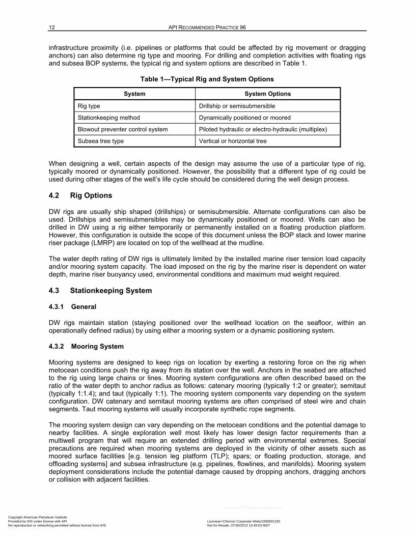
infrastructure proximity (i.e. pipelines or platforms that could be affected by rig movement or dragging anchors) can also determine rig type and mooring. For drilling and completion activities with floating rigs and subsea BOP systems, the typical rig and system options are described in Table 1.
Table 1—Typical Rig and System Options
System System Options
Rig type Drillship or semisubmersible
Stationkeeping method Dynamically positioned or moored
Blowout preventer control system Piloted hydraulic or electro-hydraulic (multiplex)
Subsea tree type Vertical or horizontal tree
When designing a well, certain aspects of the design may assume the use of a particular type of rig, typically moored or dynamically positioned. However, the possibility that a different type of rig could be used during other stages of the well’s life cycle should be considered during the well design process.
4.2 Rig Options
DW rigs are usually ship shaped (drillships) or semisubmersible. Alternate configurations can also be used. Drillships and semisubmersibles may be dynamically positioned or moored. Wells can also be drilled in DW using a rig either temporarily or permanently installed on a floating production platform. However, this configuration is outside the scope of this document unless the BOP stack and lower marine riser package (LMRP) are located on top of the wellhead at the mudline.
The water depth rating of DW rigs is ultimately limited by the installed marine riser tension load capacity and/or mooring system capacity. The load imposed on the rig by the marine riser is dependent on water depth, marine riser buoyancy used, environmental conditions and maximum mud weight required.
4.3 Stationkeeping System
4.3.1 General
DW rigs maintain station (staying positioned over the wellhead location on the seafloor, within an operationally defined radius) by using either a mooring system or a dynamic positioning system.
4.3.2 Mooring System
Mooring systems are designed to keep rigs on location by exerting a restoring force on the rig when metocean conditions push the rig away from its station over the well. Anchors in the seabed are attached to the rig using large chains or lines. Mooring system configurations are often described based on the ratio of the water depth to anchor radius as follows: catenary mooring (typically 1:2 or greater); semitaut (typically 1:1.4); and taut (typically 1:1). The mooring system components vary depending on the system configuration. DW catenary and semitaut mooring systems are often comprised of steel wire and chain segments. Taut mooring systems will usually incorporate synthetic rope segments.
The mooring system design can vary depending on the metocean conditions and the potential damage to nearby facilities. A single exploration well most likely has lower design factor requirements than a multiwell program that will require an extended drilling period with environmental extremes. Special precautions are required when mooring systems are deployed in the vicinity of other assets such as moored surface facilities [e.g. tension leg platform (TLP); spars; or floating production, storage, and offloading systems] and subsea infrastructure (e.g. pipelines, flowlines, and manifolds). Mooring system deployment considerations include the potential damage caused by dropping anchors, dragging anchors or collision with adjacent facilities.
Copyright American Petroleum Institute Provided by IHS under license with API Licensee=Chevron Corporate Wide/1000001100
Not for Resale, 07/30/2013 13:49:03 MDTNo reproduction or networking permitted without license from IHS
--``,,`,````,``,`,``,,,`,,``,`-`-`,,`,,`,`,,`---
DEEPWATER WELL DESIGN AND CONSTRUCTION 13
A limit state analysis and risk assessment are integral considerations when assessing mooring systems. Refer to API 2SK for additional information about mooring systems.
4.3.3 Dynamic Positioning System
Dynamic positioning systems are commonly used for stationkeeping on DW drilling rigs. These systems use information on the rig’s current location (e.g. as determined by a global positioning system and acoustic sensors) to control thrusters, which act to restore the rig to a position over the well’s center. Dynamically positioned drillships and semisubmersibles optimize stationkeeping by keeping the bow pointed in the direction of the metocean conditions.
Rig position offset creates bending loads in the marine riser system, subsea BOP, wellhead connector, subsea wellhead, and structural casing. These loads have the potential to be higher when using dynamically positioned rigs compared to moored rigs in the same water depth. This is because the assumed rig offset and associated loads that occur with a failure of the dynamic positioning systems are higher than the failure case for a moored system.
The rig offset-induced bending loads can be an especially important consideration if a well was initially planned to be drilled using a moored rig, but is instead drilled or reentered using a dynamically positioned rig. The structural capacity of the well should be designed for current and future rig types.
Refer to API 2SK for additional information on dynamically positioned rigs.
4.3.4 Metocean Criteria and Loading
Metocean conditions at or near the location of a DW well are an important component in the well design, its construction and operation. In general, metocean analysis considers the statistical probability of a storm event impacting the well’s location. Important metocean phenomena to be considered are primarily wind, wave, and current (tides having a secondary effect). These phenomena are converted into loads applied to the rig and its riser to determine the rig’s suitability to work at the location during the anticipated season(s). These loads can sometimes be managed or minimized by changing the heading of the rig or by adjusting the tensions on different anchoring lines.
Seasonal variation of metocean conditions is a key consideration for most locations. There can be significant differences in the metocean conditions during tropical or winter storm events versus day-to-day operations. Rig selection should consider whether the stationkeeping system can withstand the expected variation of these conditions at the well location. The range of metocean conditions can differ greatly if the rig is drilling a short-duration well during the more benign part of the calendar, compared with an extended drilling campaign stretching over multiple years in the same location. Examples of considerations include: rig survivability, riser survivability, anchor tension, rig heading for ship-shaped vessels, watch circles, and evacuation procedures.
DW well operations can be affected by different types of currents. Tidal currents are typically weak in DW, but circulation currents can be quite significant. Circulation currents are relatively steady, large-scale features of the general oceanic circulation. An example is the Loop Current in the Gulf of Mexico, where surface velocities can be in the range of approximately 2 knots to 4 knots at the surface, declining with water depth. While relatively steady, these circulation features can meander and intermittently break off from the main circulation feature to become large-scale eddies/rings, which then drift at a speed of a few kilometers per day. Velocities in such eddies or rings can approach or exceed that of the main circulation feature. Circulation currents generally will not change in magnitude or direction in a dramatic fashion. Rather changes in these currents will typically be gradual and on the order of days rather than hours.
Other current types can also be present. Rossby waves are currents with a period of several days that can occur near escarpments (such as the Sigsbee escarpment). They can generate up to 3.6 knots at the surface with 2 knots at the mudline. Inertial currents are increased currents at depth that typically reach their maximum rate several days after a storm passes the location (compared with the largest surface
Copyright American Petroleum Institute Provided by IHS under license with API Licensee=Chevron Corporate Wide/1000001100
Not for Resale, 07/30/2013 13:49:03 MDTNo reproduction or networking permitted without license from IHS
--``,,`,````,``,`,``,,,`,,``,`-`-`,,`,,`,`,,`---
14 API RECOMMENDED PRACTICE 96
currents that typically occur simultaneously with the storm's passage). For certain types of currents, the profile of the current within the water column can have a significant impact on riser loading, fatigue, and rig stationkeeping.
Refer to API 2INT-DG for guidance on hurricane-induced conditions and API 2MET for metocean conditions.
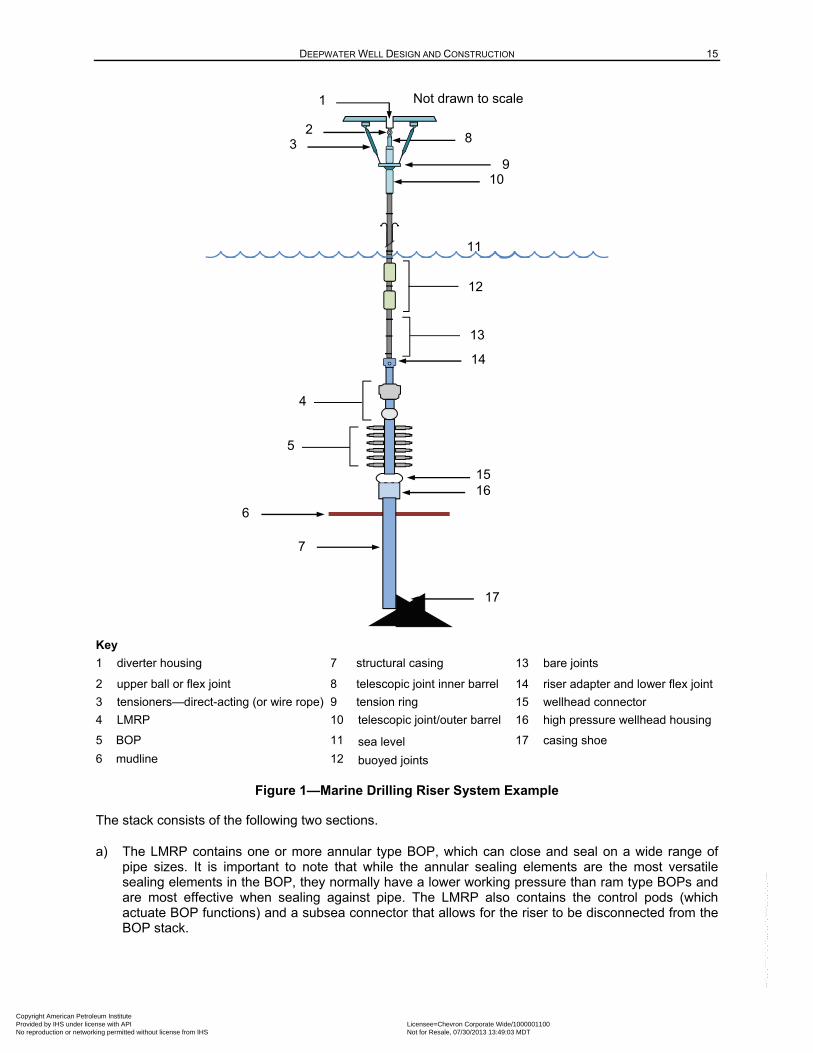
4.4 Marine Drilling Riser System
The rig is connected to the subsea wellhead with the marine drilling riser system. The riser is a conduit for equipment and for fluid circulation between the rig and the seafloor. The riser system supports the tension load applied to keep it aligned between the rig and the wellhead, along with the weight of the control lines and service lines. The riser joints include smaller, high-pressure choke and kill (C/K) lines that facilitate high-pressure circulation and well control operations. The riser system features either electrical or fiber optic cables to carry multiplexed (MUX) signals or hydraulic lines to carry pilot signals to the control the BOP and EDS systems. Specialty components (e.g. telescopic joints and tension ring) at the top of the riser system allow the rig to move up, down, and to rotate relative to the riser. Additional information can be found in API 53 and API 16Q.
Figure 1 provides an example of a marine drilling riser system.
4.5 BOP System
A subsea BOP system supports both well control and operational functions. Key functions include:
— well control—stop formation fluid influx and control existing influx during the kill operation through activation of an additional barrier;
— provide the ability to shear drill pipe, tubing, casing or other components and allow rapid release of the LMRP from the BOP stack;
— seal the well by providing a barrier to replace the loss of hydrostatic pressure in the event of a drilling riser disconnect or mechanical failure of the riser;
— provide a means of pressure testing wellbore sealing elements.
The subsea BOP incorporates multiple elements designed to close around the different sizes of drill pipe, casing, or tubing used in the well construction process. This allows circulating an influx out of the wellbore or bullheading the influx back into the formation through the C/K lines and the choke manifold. The BOP also provides the functionality of testing wellbore equipment (e.g. casing, cement, packoffs, etc.). The BOP elements and valves, are closed, pressure is applied down either the choke or kill line with the response monitored at the rig floor.
Blind shear rams (BSRs) are capable of shearing certain tubulars in addition to sealing the wellbore. A tubular may not be shearable in a particular BOP system or under certain well or operating conditions due to the size, wall thickness or material properties of that tubular. However, while some shearing elements (e.g. casing shear rams) are more capable of shearing large diameter or heavy wall tubulars, they may not be designed to seal the wellbore. Refer to API 53 and local regulations for guidance on BOP configurations.
Copyright American Petroleum Institute Provided by IHS under license with API Licensee=Chevron Corporate Wide/1000001100
Not for Resale, 07/30/2013 13:49:03 MDTNo reproduction or networking permitted without license from IHS
--``,,`,````,``,`,``,,,`,,``,`-`-`,,`,,`,`,,`---
DEEPWATER WELL DESIGN AND CONSTRUCTION 15
Key
1 diverter housing 7 structural casing 13 bare joints
2 upper ball or flex joint 8 telescopic joint inner barrel 14 riser adapter and lower flex joint
3 tensioners—direct-acting (or wire rope) 9 tension ring 15 wellhead connector
4 LMRP 10 telescopic joint/outer barrel 16 high pressure wellhead housing
5 BOP 11 sea level 17 casing shoe
6 mudline 12 buoyed joints
Figure 1—Marine Drilling Riser System Example
The stack consists of the following two sections.
a) The LMRP contains one or more annular type BOP, which can close and seal on a wide range of pipe sizes. It is important to note that while the annular sealing elements are the most versatile sealing elements in the BOP, they normally have a lower working pressure than ram type BOPs and are most effective when sealing against pipe. The LMRP also contains the control pods (which actuate BOP functions) and a subsea connector that allows for the riser to be disconnected from the BOP stack.
10
12
11
3
1
2 8
Not drawn to scale
4
5
6
13
7
14
1516
17
9
Copyright American Petroleum Institute Provided by IHS under license with API Licensee=Chevron Corporate Wide/1000001100
Not for Resale, 07/30/2013 13:49:03 MDTNo reproduction or networking permitted without license from IHS
--``,,`,````,``,`,``,,,`,,``,`-`-`,,`,,`,`,,`---
16 API RECOMMENDED PRACTICE 96
b) The BOP stack contains ram-type elements and may contain an annular BOP. These elements can include:
— fixed pipe rams,
— variable bore rams,
— shearing rams,
— test rams,
— BSRs, and
— blind rams.
Sealing elements (annulars or rams) are designed to seal against pressure exerted from the wellbore. While all rams are designed to hold their stated pressures in one direction (typically in the direction of hydrocarbon flow), they are not all designed to hold the same level of pressure in the opposite direction (thus potentially creating a leak path during a negative test). On some rigs, an inverted ram or a specially designed bidirectional ram (test ram) is used to hold pressure from above, eliminating the need for a test plug or tool during BOP pressure tests or negative testing of barriers. A variable bore ram is a standard pipe ram that seals on a range of pipe sizes using a special elastomer and elastomer support mechanism that adapts to the pipe size during the closing operation.
The C/K line system is considered part of the BOP system. When the BOP is closed, the C/K lines provide a means to circulate fluids into or out of the well, circulate out a kick, monitor pressures and test the BOP. When operating in deeper water depths with longer C/K lines, the use of large inner diameter (ID) lines can improve circulation and well control capabilities by reducing dynamic friction loss through these lines.
It is critical that the BOPs and wellhead system have sufficient structural integrity to withstand the combined pressure, tension, and bending loads. Subsea BOPs contain elements and valves joined together with either flanged, studded, or clamp hub connections. C/K line outlets are subjected to bending loads from the pressure end loads applied to the ID of the C/K line at the lower-most valve. The bending resistance of BOP connections is reduced as internal pressure increases. To provide additional assurance the BOP component connections do not leak under combined pressure and bending loads, methods of resisting the bending loads may be included in the BOP frame design. Additional information about API flange connections can be found in API 6AF, API 6AF1 and API 6AF2.
Periodic BOP system inspections shall be conducted to meet or exceed the provisions established in API 53.
4.6 BOP Control System
4.6.1 General
BOP functions are controlled using several methods such as direct, piloted, electro-hydraulic, and MUX. One method employs piloted hydraulic controls. In this case, a hydraulic signal is transmitted from the surface control station to the subsea BOP. A hydraulic pilot valve receives the signal triggering the actuation of the subsea function. Because the hydraulic signal travels slowly, this type of control is best suited for use in shallower water depths. Another type of control uses electro-hydraulic technology. Systems in deeper water depths use multiplexed electrical or fiber optic signals sent from the surface to the pods to actuate the function on the subsea BOP.
To increase the reliability of the control system, two independent control pods (located on the LMRP) provide separate communication paths to the BOP (which can be selected at the surface control panel).
Copyright American Petroleum Institute Provided by IHS under license with API Licensee=Chevron Corporate Wide/1000001100
Not for Resale, 07/30/2013 13:49:03 MDTNo reproduction or networking permitted without license from IHS
--``,,`,````,``,`,``,,,`,,``,`-`-`,,`,,`,`,,`---
DEEPWATER WELL DESIGN AND CONSTRUCTION 17
The selected control path to activate BOP functions is through either the blue pod or the yellow pod on the LMRP (refer to Figure 2).
Most DW rigs use electronic BOP control systems based on MUX communication protocols that transmit signals in milliseconds. MUX systems are highly complex, and their multiple hydraulic/electric interfaces require diligent maintenance and testing. Some systems have batteries installed in the pod, and in those cases it is important to consider how to maintain the power in those batteries. Modern MUX systems provide multiple levels of system redundancy beyond being able to select the blue or yellow pod control system paths.
With either piloted hydraulic or MUX systems, the control system is used to direct the flow of hydraulic fluid to various hydraulically operated components in the BOP system. The control system valve package (commonly referred to as the pod) is where the individual surface-generated control signals activate the selected valve to direct hydraulic fluid to the required BOP function (for example, to close a pipe ram). Hydraulic fluid is provided via a conduit line, or hose from the surface high pressure unit. The typical DW 5000 psi accumulator supply pressure is commonly regulated to a lower operating pressure to actuate specific BOP functions. BOP hydraulic fluid is a water-based fluid with soluble oil additives for lubricity and corrosion control.
Verification feedback to the BOP control panels on the rig includes the volume of BOP control fluid and pressure used to activate a function. Any discrepancy between the indicated and the expected volumes should be noted and investigated.
NOTE The expected operating volume is determined during prior testing of the BOPs.
Any modifications from the original design or the intended function of the BOP and control system shall require a documented risk assessment by the contractor to accompany the required MOC.
Additional information about BOP control systems can be found in API 16D and in API 53.
4.6.2 Remotely Operated Vehicle Panel
The BOP stack should be equipped with the following minimum (critical) ROV intervention capability to:
⎯ close each shear ram (and lock),
⎯ close one pipe ram (and lock), and
⎯ unlatch the wellhead connector.
A hydraulic power source able to interface with the ROV panel shall be available on the rig and ready for deployment when the BOP is installed on the subsea wellhead.
All critical functions shall be fitted with API 17H high-flow receptacles. Critical functions shall be color designated for quick identification, to differentiate the critical functions from the noncritical functions.
Frequency of testing and acceptance criteria shall be in accordance with API 53 and local regulations. Additional information about ROV interface panels can be found in API 16D.
4.6.3 Acoustic System
Secondary control of key functions can also be provided via an independent acoustic BOP control system that can be activated using a matching portable acoustic control unit on the rig or nearby vessel. The reliability of acoustic systems can be adversely affected by thermoclines, currents, and vessel noise (i.e. during a drive-off). Additional information on BOP control system functions can be found in API 16D.
Copyright American Petroleum Institute Provided by IHS under license with API Licensee=Chevron Corporate Wide/1000001100
Not for Resale, 07/30/2013 13:49:03 MDTNo reproduction or networking permitted without license from IHS
--``,,`,````,``,`,``,,,`,,``,`-`-`,,`,,`,`,,`---
18 API RECOMMENDED PRACTICE 96
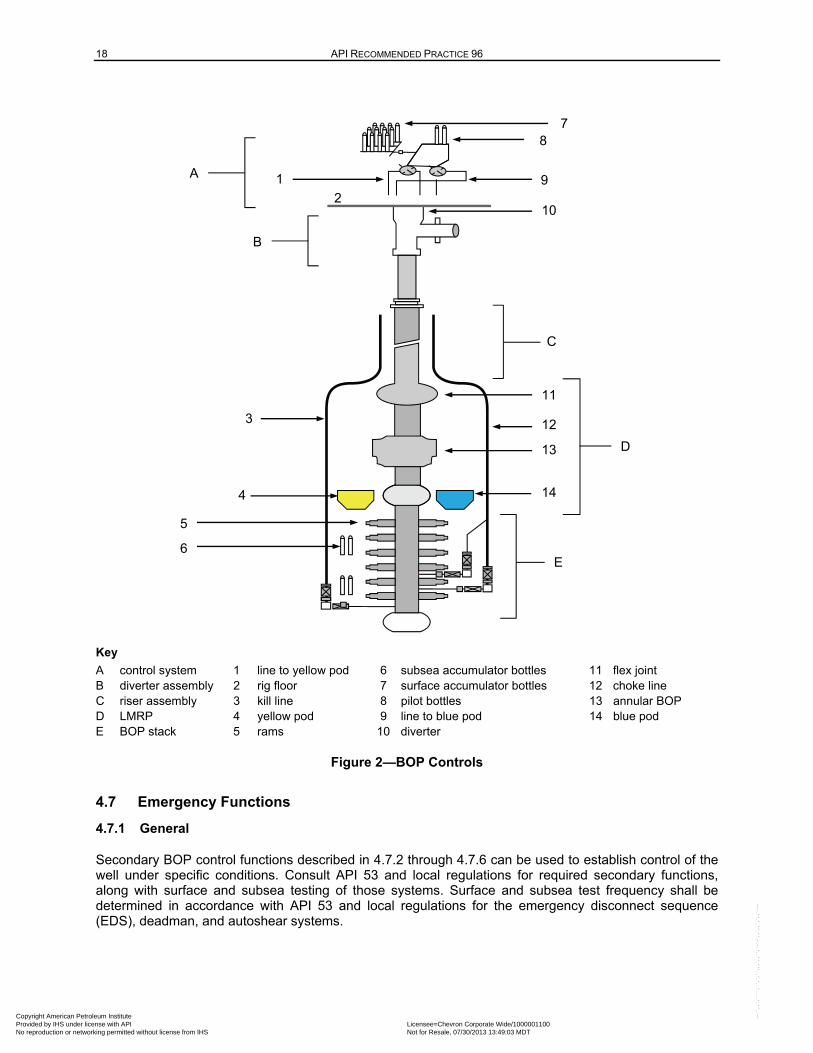
Key
A control system 1 line to yellow pod 6 subsea accumulator bottles 11 flex joint B diverter assembly 2 rig floor 7 surface accumulator bottles 12 choke line C riser assembly 3 kill line 8 pilot bottles 13 annular BOP D LMRP 4 yellow pod 9 line to blue pod 14 blue pod E BOP stack 5 rams 10 diverter
Figure 2—BOP Controls
4.7 Emergency Functions
4.7.1 General
Secondary BOP control functions described in 4.7.2 through 4.7.6 can be used to establish control of the well under specific conditions. Consult API 53 and local regulations for required secondary functions, along with surface and subsea testing of those systems. Surface and subsea test frequency shall be determined in accordance with API 53 and local regulations for the emergency disconnect sequence (EDS), deadman, and autoshear systems.
E
D
C
B
A
1
2
3
4
5
8
9
10
11
12
13
14
6
7
Copyright American Petroleum Institute Provided by IHS under license with API Licensee=Chevron Corporate Wide/1000001100
Not for Resale, 07/30/2013 13:49:03 MDTNo reproduction or networking permitted without license from IHS
--``,,`,````,``,`,``,,,`,,``,`-`-`,,`,,`,`,,`---
DEEPWATER WELL DESIGN AND CONSTRUCTION 19
4.7.2 Emergency Disconnect Sequence
The EDS is a manually-activated function programmed to shut the well in and disconnect the LMRP from the BOP stack, based on the well conditions and vessel-specific operating criteria. There is no system or trigger mechanism that automatically begins the EDS sequence. It is manually activated by pushing the EDS button. An EDS is normally limited to rigs with dynamic positioning systems.
The EDS sequencing varies depending on the specific system, anticipated disconnect scenario, and input from the contractor, and operator. For example, the order of disconnect may begin with the casing shear rams (nonsealing), followed by the BSRs (sealing). The accumulator volume and pressures, ram operator system pressures, and ram shearing capabilities should all be considered in the design. The frequency of testing and acceptance criteria shall be in accordance with API 53 and local regulations.
If the marine riser is suddenly disconnected with a full mud column, the collapse loads induced by the falling mud column should be considered.
4.7.3 Deadman
A deadman system shall be installed, tested and available on all moored and dynamically positioned rigs, where subsea BOPs are installed, in accordance with API 53 and local regulations. When the deadman system is activated under intended conditions, it does not require human initiation. The subsea accumulator volume and pressure required to secure the well in the event of a complete loss of electrical power, communications and hydraulics to the subsea control system, shall be determined for the system installed, in accordance with API 16D. Some deadman systems rely on subsea battery power to operate. If this is the case, procedures should be in place to monitor or track the charge state of the battery pack.
If the electrical or hydraulic communication link to only one pod is lost, the deadman will not activate. A typical design includes a fail-open valve that blocks subsea accumulator supply to the BSRs (when powered). Upon sensing the loss of hydraulic supply and electrical power from both pods, the valve opens and the BSRs close. Other secondary functions may be attached to the deadman system such as closing of C/K fail-closed valves (loss of pilot pressure) or LMRP disconnect.
Standard operating procedures for pod reactivation, including control logic to prevent the BSR from inadvertently opening when power is reestablished to the BOP stack after a disconnect, shall be established. These procedures shall also be included in the deck testing of the system prior to deploying the BOP.
4.7.4 Autoshear
Autoshear is a safety system that is designed to automatically shut-in the wellbore in the event of an accidental disconnect of the LMRP. When the autoshear is armed, the shear rams close when the LMRP is disconnected. Since this system must operate rapidly despite having lost the connection to the rig, a separate accumulator system is used for the autoshear and deadman.
NOTE This accumulator system may also be used to operate the ROV and acoustic systems.
The autoshear system is occasionally disarmed according to company-specific and rig-specific procedures, typically when nonshearable components are positioned within the stack. However, a MOC should be used if the autoshear system is disarmed for other reasons (i.e. a leak in bottle or manifold).
When moving the BOPs between wells, the benefits of retesting the system subsea versus the risk of damaging the well or rig equipment if the BOPs are pulled to surface for testing should be considered.
Frequency of testing and acceptance criteria shall be in accordance with API 53 and local regulations.
Copyright American Petroleum Institute Provided by IHS under license with API Licensee=Chevron Corporate Wide/1000001100
Not for Resale, 07/30/2013 13:49:03 MDTNo reproduction or networking permitted without license from IHS
--``,,`,````,``,`,``,,,`,,``,`-`-`,,`,,`,`,,`---
20 API RECOMMENDED PRACTICE 96
4.8 Subsea Wellhead and Production Tree Configurations
A low pressure wellhead housing (LPWH) is welded to the structural casing and serves as foundational structure for the HPWHH. A permanent guide base, when used, attaches to the LPWH.
The high pressure wellhead housing (HPWHH), with its welded extension, is attached to the top of the surface casing. The wellhead provides an external connector profile to which the subsea BOP stack is attached. It has several internal profiles for casing hangers, running tools, and seal assemblies. It is normally latched and often preloaded to the LPWH to increase both bending and rotational resistance.
For wells that will be completed, the subsea production tree is attached to the HPWHH. There are two types of subsea production trees: vertical and horizontal. A vertical subsea tree can require a tubing spool.
The type of subsea production tree will have an impact on sequence of completion activities and on the subsea BOP/LMRP configuration for well control during some completion operations.
4.9 Remotely Operated Vehicle Systems
ROV systems can be used in drilling and completion of DW wells. In some operations, multiple ROVs are used to provide redundancy allowing continuous activity in the event of a failure of one ROV. ROVs are used in open water activities before running the BOPs, for secondary (or emergency) activation of the BOP functions and in completion and abandonment activities. A ROV may also provide the following functions in support of the well construction process:
a) normal/high definition camera for routine inspection of the equipment, riser, and BOP condition during operations;
b) hydraulic pump to provide seawater or corrosion prevention fluid to activate BOP functions;
c) compass to determine relative heading of objects with respect to wellhead;
d) fluid bladder to enable pumping corrosion prevention fluid into wellhead;
e) sonar for detection of objects;
f) multifunction arms to rotate bolts to lock/unlock components and pull/reinstall plug-ins;
g) install, remove, and replace ring gaskets on the subsea wellhead and LMRP;
h) tooling packages for subsea equipment;
i) hot-stab capability;
j) hydrate removal;
k) hydrate suppression by pumping glycol or methanol;
l) monitor structural, conductor, and surface pipe running operations;
m) monitor fluid returns during riserless drilling and cementing operations;
n) move guidelines and guide posts from one guide base to another.
Refer to API 53 and API 17H (or ISO 13628-8) for additional information.
NOTE Some rigs may use guidelines, installed between the moonpool and the LPWH, which allow a rig-based video system to be run on a cable to monitor operations.
Copyright American Petroleum Institute Provided by IHS under license with API Licensee=Chevron Corporate Wide/1000001100
Not for Resale, 07/30/2013 13:49:03 MDTNo reproduction or networking permitted without license from IHS
--``,,`,````,``,`,``,,,`,,``,`-`-`,,`,,`,`,,`---
DEEPWATER WELL DESIGN AND CONSTRUCTION 21
5 Well Design Considerations
5.1 General
The basis for a well design is an understanding of the environment in which the well is to be drilled. Interpretations of local geologic structure, geo-pressure, and formation strengths are derived from local drilling experience or seismic data. It should be noted that uncertainties will exist in the interpretation of the data and ultimately in the description of the geologic environment.
Casing design is based on these interpretations and other factors. For example, location-specific constraints establish the directional drilling program and the required well depth. Production or evaluation requirements will dictate the hole size desired at total depth (TD).
The integration of casing design with barrier planning contributes to increased reliability and well integrity. The resulting well architecture is intended to safely achieve well objectives.
NOTE The terminology used to identify casing types (refer to Table 2) is dependent on local regulations and convention (e.g. surface casing, conductor casing, structural casing).
5.2 Deepwater Well Architecture
The complexity of DW wells has increased over the years as measured by water depth, well depth, mud weights, temperatures, and the number of casing points required to reach the objectives. DW wells now have been drilled in water depths greater than 10,000 ft (3048 m) and to true vertical depths greater than 35,000 ft (10,668 m). Examples of complexities that impact well architecture are provided in the following:
a) low fracture pressure relative to pore pressure in DW environments (drilling margin);
b) salt and subsalt hazards such as tar zones or rubble zones;
c) subsurface geology including shallow water/gas flow hazards and in situ hydrates;
d) abnormal pore pressure or subnormal pressures (regressions);
e) metocean (heave compensation as well as mooring during hurricanes and stationkeeping during loop currents);
f) drilling duration, casing wear, and heat checking of casing due to extended drill pipe rotation and side loads;
g) thermal fluid expansion and trapped annular pressure loads;
h) wellhead and hanger load capacities and reduced annular clearance;
i) BOP limitations [e.g. shear limitations regarding heavy-wall high-strength drill strings, annular element sealing on large outer diameter (OD) casing, and the potential for casing collapse when an annular BOP is closed on large OD casing];
j) directional requirements;
k) presence of H2S (e.g. water flooding);
l) permanent abandonments, including wellhead removal.
Copyright American Petroleum Institute Provided by IHS under license with API Licensee=Chevron Corporate Wide/1000001100
Not for Resale, 07/30/2013 13:49:03 MDTNo reproduction or networking permitted without license from IHS
--``,,`,````,``,`,``,,,`,,``,`-`-`,,`,,`,`,,`---
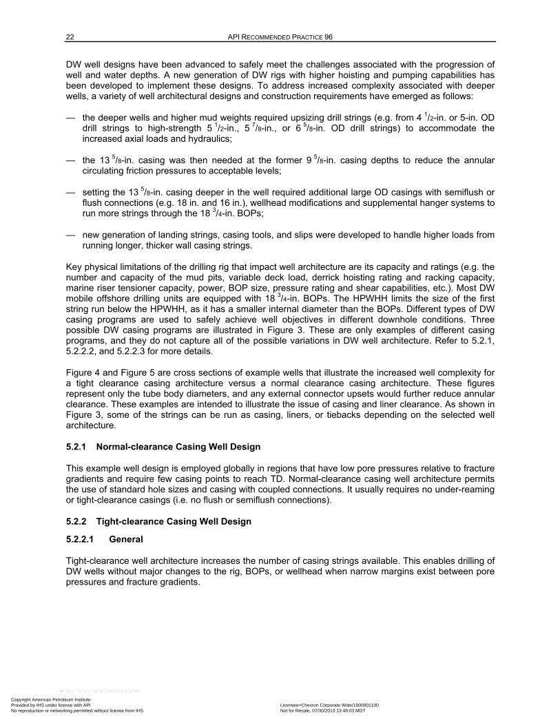
22 API RECOMMENDED PRACTICE 96
DW well designs have been advanced to safely meet the challenges associated with the progression of well and water depths. A new generation of DW rigs with higher hoisting and pumping capabilities has been developed to implement these designs. To address increased complexity associated with deeper wells, a variety of well architectural designs and construction requirements have emerged as follows:
— the deeper wells and higher mud weights required upsizing drill strings (e.g. from 4 1/2-in. or 5-in. OD drill strings to high-strength 5 1/2-in., 5 7/8-in., or 6 5/8-in. OD drill strings) to accommodate the increased axial loads and hydraulics;
— the 13 5/8-in. casing was then needed at the former 9 5/8-in. casing depths to reduce the annular circulating friction pressures to acceptable levels;
— setting the 13 5/8-in. casing deeper in the well required additional large OD casings with semiflush or flush connections (e.g. 18 in. and 16 in.), wellhead modifications and supplemental hanger systems to run more strings through the 18 3/4-in. BOPs;
— new generation of landing strings, casing tools, and slips were developed to handle higher loads from running longer, thicker wall casing strings.
Key physical limitations of the drilling rig that impact well architecture are its capacity and ratings (e.g. the number and capacity of the mud pits, variable deck load, derrick hoisting rating and racking capacity, marine riser tensioner capacity, power, BOP size, pressure rating and shear capabilities, etc.). Most DW mobile offshore drilling units are equipped with 18 3/4-in. BOPs. The HPWHH limits the size of the first string run below the HPWHH, as it has a smaller internal diameter than the BOPs. Different types of DW casing programs are used to safely achieve well objectives in different downhole conditions. Three possible DW casing programs are illustrated in Figure 3. These are only examples of different casing programs, and they do not capture all of the possible variations in DW well architecture. Refer to 5.2.1, 5.2.2.2, and 5.2.2.3 for more details.
Figure 4 and Figure 5 are cross sections of example wells that illustrate the increased well complexity for a tight clearance casing architecture versus a normal clearance casing architecture. These figures represent only the tube body diameters, and any external connector upsets would further reduce annular clearance. These examples are intended to illustrate the issue of casing and liner clearance. As shown in Figure 3, some of the strings can be run as casing, liners, or tiebacks depending on the selected well architecture.
5.2.1 Normal-clearance Casing Well Design
This example well design is employed globally in regions that have low pore pressures relative to fracture gradients and require few casing points to reach TD. Normal-clearance casing well architecture permits the use of standard hole sizes and casing with coupled connections. It usually requires no under-reaming or tight-clearance casings (i.e. no flush or semiflush connections).
5.2.2 Tight-clearance Casing Well Design
5.2.2.1 General
Tight-clearance well architecture increases the number of casing strings available. This enables drilling of DW wells without major changes to the rig, BOPs, or wellhead when narrow margins exist between pore pressures and fracture gradients.
Copyright American Petroleum Institute Provided by IHS under license with API Licensee=Chevron Corporate Wide/1000001100
Not for Resale, 07/30/2013 13:49:03 MDTNo reproduction or networking permitted without license from IHS
--``,,`,````,``,`,``,,,`,,``,`-`-`,,`,,`,`,,`---
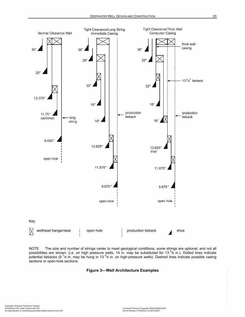
DEEPWATER WELL DESIGN AND CONSTRUCTION 23
Key
wellhead hanger/seal open hole production tieback shoe
NOTE The size and number of strings varies to meet geological conditions, some strings are optional, and not all possibilities are shown. (i.e. on high pressure wells, 14 in. may be substituted for 13 5/8 in.). Dotted lines indicate potential tiebacks (9 7/8 in. may be hung in 13 5/8 in. on high-pressure wells). Dashed lines indicate possible casing sections or open-hole sections.
Figure 3—Well Architecture Examples
Copyright American Petroleum Institute Provided by IHS under license with API Licensee=Chevron Corporate Wide/1000001100
Not for Resale, 07/30/2013 13:49:03 MDTNo reproduction or networking permitted without license from IHS
--``,,`,````,``,`,``,,,`,,``,`-`-`,,`,,`,`,,`---
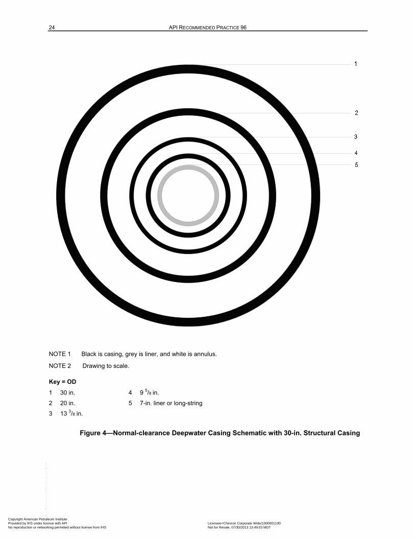
24 API RECOMMENDED PRACTICE 96
NOTE 1 Black is casing, grey is liner, and white is annulus.
NOTE 2 Drawing to scale.
Key = OD
1 30 in. 4 9 5/8 in.
2 20 in. 5 7-in. liner or long-string
3 13 3/8 in.
Figure 4—Normal-clearance Deepwater Casing Schematic with 30-in. Structural Casing
Copyright American Petroleum Institute Provided by IHS under license with API Licensee=Chevron Corporate Wide/1000001100
Not for Resale, 07/30/2013 13:49:03 MDTNo reproduction or networking permitted without license from IHS
--``,,`,````,``,`,``,,,`,,``,`-`-`,,`,,`,`,,`---
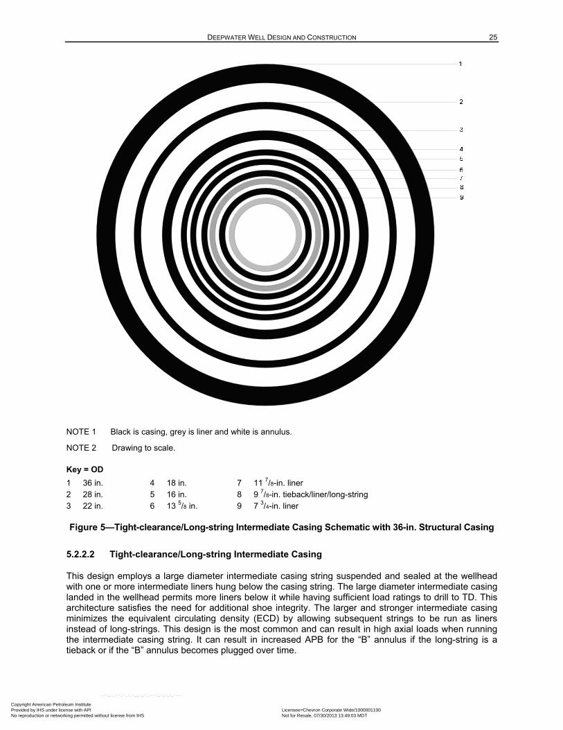
DEEPWATER WELL DESIGN AND CONSTRUCTION 25
NOTE 1 Black is casing, grey is liner and white is annulus.
NOTE 2 Drawing to scale.
Key = OD
1 36 in. 4 18 in. 7 11 7/8-in. liner 2 28 in. 5 16 in. 8 9 7/8-in. tieback/liner/long-string 3 22 in. 6 13 5/8 in. 9 7 3/4-in. liner
Figure 5—Tight-clearance/Long-string Intermediate Casing Schematic with 36-in. Structural Casing
5.2.2.2 Tight-clearance/Long-string Intermediate Casing
This design employs a large diameter intermediate casing string suspended and sealed at the wellhead with one or more intermediate liners hung below the casing string. The large diameter intermediate casing landed in the wellhead permits more liners below it while having sufficient load ratings to drill to TD. This architecture satisfies the need for additional shoe integrity. The larger and stronger intermediate casing minimizes the equivalent circulating density (ECD) by allowing subsequent strings to be run as liners instead of long-strings. This design is the most common and can result in high axial loads when running the intermediate casing string. It can result in increased APB for the “B” annulus if the long-string is a tieback or if the “B” annulus becomes plugged over time.
Copyright American Petroleum Institute Provided by IHS under license with API Licensee=Chevron Corporate Wide/1000001100
Not for Resale, 07/30/2013 13:49:03 MDTNo reproduction or networking permitted without license from IHS
--``,,`,````,``,`,``,,,`,,``,`-`-`,,`,,`,`,,`---
26 API RECOMMENDED PRACTICE 96
5.2.2.3 Tight-clearance/Heavy-wall Surface Casing
This design employs a heavy-wall, high-strength extension within the surface casing immediately below the HPWHH. The high pressure supplemental casing hanger adapter is installed in the heavy-wall, high-strength surface casing above the thinner wall surface casing. This design allows hanging of a casing (e.g. 16 in.) without using a hanger position in the HPWHH.
Benefits of the design are the following:
— lower ECDs due to greater clearances;
— can simplify plug and abandonment operations if supplemental casing hanger is set deeper in the well;
— allows larger diameter tiebacks due to the increased internal diameter of the heavy-wall surface casing;
— reduces the number of annuli at the wellhead that can affect the APB design;
— changes the “B” annulus by removing the intermediate long-string casing from the wellhead by replacing it with a liner (eliminates the normal “B” annulus).
This design exposes fabrication welds between the HPWHH and the supplemental adapter to the pressures and temperatures at TD, or until casing is run/tied back in the HPWHH.
Table 2 lists and describes typical casing types.
NOTE Production casing or tiebacks may be run as tapered strings if required to accommodate large diameter SCSSVs.
5.2.3 Completion Architecture
The objective of the completion architecture is to achieve the desired production or injection rates over the life of the well. This completion architecture forms the basis for selecting the production casing size.
These items can affect the design of the completion architecture:
— tubing size to achieve the desired well inflow/injection rate;
— sandface completion design;
— size of upper completion components (i.e. SCSSV, inflow control devices, injection subs);
— recompletion and fishability of completion components;
— control lines and chemical injection lines;
— artificial lift design;
— flow assurance requirements.
NOTE Refer to Section 9 for special considerations for completions.
Copyright American Petroleum Institute Provided by IHS under license with API Licensee=Chevron Corporate Wide/1000001100
Not for Resale, 07/30/2013 13:49:03 MDTNo reproduction or networking permitted without license from IHS
--``,,`,````,``,`,``,,,`,,``,`-`-`,,`,,`,`,,`---
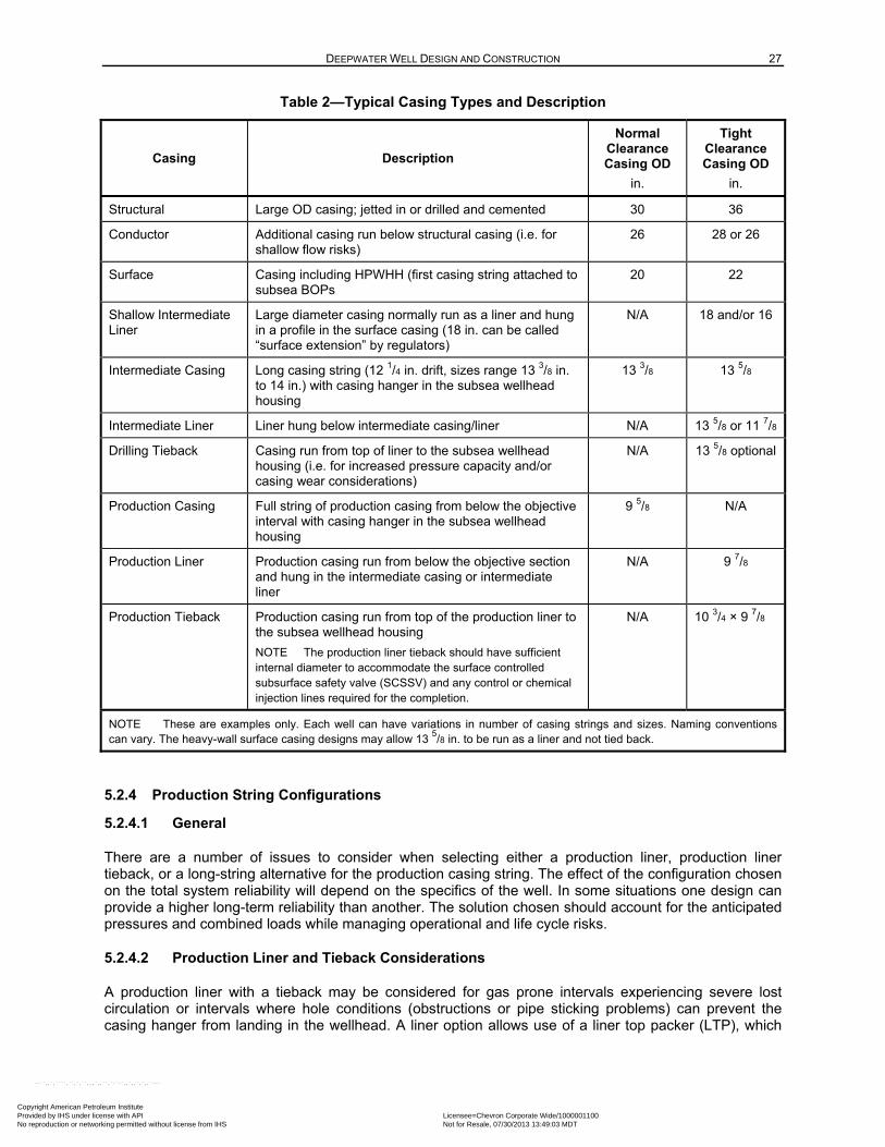
DEEPWATER WELL DESIGN AND CONSTRUCTION 27
Table 2—Typical Casing Types and Description
Casing Description
Normal Clearance Casing OD
in.
Tight Clearance Casing OD
in.
Structural Large OD casing; jetted in or drilled and cemented 30 36
Conductor Additional casing run below structural casing (i.e. for shallow flow risks)
26 28 or 26
Surface Casing including HPWHH (first casing string attached to subsea BOPs
20 22
Shallow Intermediate Liner
Large diameter casing normally run as a liner and hung in a profile in the surface casing (18 in. can be called “surface extension” by regulators)
N/A 18 and/or 16
Intermediate Casing Long casing string (12 1/4 in. drift, sizes range 13 3/8 in. to 14 in.) with casing hanger in the subsea wellhead housing
13 3/8 13 5/8
Intermediate Liner Liner hung below intermediate casing/liner N/A 13 5/8 or 11 7/8
Drilling Tieback Casing run from top of liner to the subsea wellhead housing (i.e. for increased pressure capacity and/or casing wear considerations)
N/A 13 5/8 optional
Production Casing Full string of production casing from below the objective interval with casing hanger in the subsea wellhead housing
9 5/8 N/A
Production Liner Production casing run from below the objective section and hung in the intermediate casing or intermediate liner
N/A 9 7/8
Production Tieback Production casing run from top of the production liner to the subsea wellhead housing
NOTE The production liner tieback should have sufficient internal diameter to accommodate the surface controlled subsurface safety valve (SCSSV) and any control or chemical injection lines required for the completion.
N/A 10 3/4 × 9 7/8
NOTE These are examples only. Each well can have variations in number of casing strings and sizes. Naming conventions can vary. The heavy-wall surface casing designs may allow 13
5/8 in. to be run as a liner and not tied back.
5.2.4 Production String Configurations
5.2.4.1 General
There are a number of issues to consider when selecting either a production liner, production liner tieback, or a long-string alternative for the production casing string. The effect of the configuration chosen on the total system reliability will depend on the specifics of the well. In some situations one design can provide a higher long-term reliability than another. The solution chosen should account for the anticipated pressures and combined loads while managing operational and life cycle risks.
5.2.4.2 Production Liner and Tieback Considerations
A production liner with a tieback may be considered for gas prone intervals experiencing severe lost circulation or intervals where hole conditions (obstructions or pipe sticking problems) can prevent the casing hanger from landing in the wellhead. A liner option allows use of a liner top packer (LTP), which
Copyright American Petroleum Institute Provided by IHS under license with API Licensee=Chevron Corporate Wide/1000001100
Not for Resale, 07/30/2013 13:49:03 MDTNo reproduction or networking permitted without license from IHS
--``,,`,````,``,`,``,,,`,,``,`-`-`,,`,,`,`,,`---
28 API RECOMMENDED PRACTICE 96
may be set after cementing. The LTP provides a mechanical barrier that isolates the open-hole section after it is set. Pressure testing a LTP does not confirm zonal isolation by the cement.
The liner option allows the casing to be hung at any depth if the string does not reach bottom. It also enhances well control by increasing the time during which the pipe rams can be closed on the drill pipe running string during liner installation.
The liner hanger system should be selected based on the expected pressures and combined loads. Close tolerance liner hangers (e.g. 13 5/8 × 11 7/8 and 11 7/8 × 9 5/8) can have reduced burst and collapse ratings when compared to the high-strength tubulars used in many liners. If increased pressure ratings are required, consideration can be given to hanging the liner in the next larger string or to other alternatives (e.g. tieback receptacle placed below hanger to increase system rating).
Additionally, the ability to execute a successful cement job and obtain adequate isolation should be considered. Depending on well conditions and equipment, liners may be rotated or reciprocated during cementing, which can increase mud-to-cement displacement efficiency in the annulus. The shorter annulus section (open hole remains the same but the cased hole section is reduced with a liner), combined with the concern for bringing cement above the liner, typically results in less cement volume being pumped versus a long-string option, unless the planned TOC for the long-string is reduced by APB considerations. Less cement volume could increase the potential for cement contamination. Refer to API 65-2 for additional cementing considerations.
Liner hanger geometries create annular restrictions with reduced flow by areas that can result in annular flow paths that yield higher or lower frictional pressures (compared to long-strings) when circulating. Depending upon liner hanger and well geometry, a liner configuration could have a lower ECD, which can increase the probability of a obtaining a successful cement job. The liner configuration can provide more opportunities for barrier replacement in the event of a cement job that does not meet expectations. Refer to 5.3.4.5 and B.3 for information on verification of annular cement barriers. A liner configuration can provide additional annular barriers (i.e. installation and verification of a LTP or cemented tieback string).
Well designs that include production liners may require a production tieback to accommodate the producing pressures and combined loads. The addition of a production tieback increases the complexity of the well construction and the following should be considered:
— the tieback stem and liner polished bore receptacle (PBR) interface design;
— installation space-out to engage the tieback stem seals when the casing hanger is landed in the wellhead;
— tieback anchoring method to limit seal movement during the well’s life cycle;
— an additional trapped annulus subject to APB loads.
5.2.4.3 Long-string Considerations
When using a long-string for the production casing, the following aspects of the casing annulus barrier plan should be considered:
a) two verifiable physical barriers (i.e. annular cement and the casing hanger seal);
b) addition of supplemental annular barriers (e.g. swellable packers or inflatable packers in the annulus);
c) slurry design, placement, and verification;
d) short transition times, anti-gas migration properties, fluid loss, rheology;
Copyright American Petroleum Institute Provided by IHS under license with API Licensee=Chevron Corporate Wide/1000001100
Not for Resale, 07/30/2013 13:49:03 MDTNo reproduction or networking permitted without license from IHS
--``,,`,````,``,`,``,,,`,,``,`-`-`,,`,,`,`,,`---
DEEPWATER WELL DESIGN AND CONSTRUCTION 29
e) lost circulation during cementing from ECD due to long, small annular clearances;
f) can limit displacement rates with the potential for poor displacement efficiency;
g) wells that experience losses or have poor mud/cement displacement efficiency during cementing can require increased levels of evaluation to confirm the cement barrier (refer to Table B.3);
h) primary cement barrier quality;
i) potential for annular gas migration resulting in additional casing and wellhead loads;
j) the effect of thermal cooling of the mud, which can change hydrostatic pressure prior to cement set;
k) mitigation options (refer to Table B.3);
l) casing hanger lockdown requirements (refer to 6.2.1);
m) exposure time with nonshearable items across the BOP stack when selecting either a liner or long-string option. Refer to 8.2.3.1 for additional information.
In addition, the ability to execute a successful cement job to obtain isolation should be considered. Depending on well conditions and equipment, liners may be rotated or reciprocated during cementing, which can increase mud-to-cement displacement efficiency in the annulus. To ensure proper space out, long-strings are usually landed in the wellhead housing prior to cementing; therefore, the lack of pipe movement reduces the mud-to-cement displacement efficiency in the annulus. Furthermore, as a result of long and tight annular clearances, additional ECD can be experienced, further complicating the cement job.
Refer to API 65-2 for additional cementing considerations. Refer to 5.3.4.5 and Annex B for information on verification of annular cement barriers.
5.3 Barrier Philosophy
5.3.1 General
This section describes how physical barriers and operational barriers contribute to well system reliability with respect to well control. It describes the principles, processes, and procedures for planning and implementing barriers. In this RP, barriers are defined as components or practices that contribute to the total system reliability to prevent or stop formation fluid or gas flow.
Apply the barrier philosophy to each potential flow path, while bearing in mind the consequences of a loss of well control. Follow local regulations related to barrier implementation.
5.3.2 Barrier Functionality
A petroleum well is a pathway through subsurface formations to a reservoir target that potentially contains hydrocarbons. As the well is constructed, barriers are installed to prevent flow from these formations from taking undesired paths (either to the surface or within the well). If a commercial quantity of hydrocarbons is discovered, final casing is set and a completion is installed to reliably contain the desired flow of production to the surface while the barriers prevent flow from taking undesired paths.
A system of multiple barriers is used to achieve a high level of reliability. The historical reliability of subsea well operations confirms that the philosophy of multiple barriers is effective. The well reliability is achieved through the combination of the individual barriers as a system and is not the result of the infallibility of a single component.
Copyright American Petroleum Institute Provided by IHS under license with API Licensee=Chevron Corporate Wide/1000001100
Not for Resale, 07/30/2013 13:49:03 MDTNo reproduction or networking permitted without license from IHS
--``,,`,````,``,`,``,,,`,,``,`-`-`,,`,,`,`,,`---
30 API RECOMMENDED PRACTICE 96
The designer's objective is to achieve a high level of well reliability by combining operational and physical barriers. Physical barriers contribute to a high level of reliability. Operational barriers depend on human recognition and response; however, when combined with properly designed, installed, and tested physical barriers, operational barriers significantly increase well reliability. Operational barriers also include institutional controls such as casing design standards and policy manuals.
The reliability of any physical barrier is increased if its integrity is tested to anticipated loads (i.e. in the direction of flow), after the barrier is deployed. Sometimes testing cannot be used to verify barrier integrity because potential load directions or anticipated loads cannot be simulated within the well. In these situations, more emphasis is placed on maximizing the reliability of the barrier by increasing quality control (QC) during design, manufacturing, and installation. If a barrier cannot be tested, its placement should be confirmed to the degree possible. Additionally, operational barriers are used to provide assurance that any failure of a physical barrier is detected early and managed without loss of well control.
Physical barriers (properly designed, installed and tested) contribute the most to the well reliability because of their very low failure rates. Operational barriers also increase the reliability of the well system. They become particularly important when the physical barrier system cannot be tested.
General recommendations that may be considered by the well designer and operations personnel are as follows.
a) Assume that any single well barrier can fail, even those that are verified. The potential consequences of failure of each well barrier should be considered, and the required contingencies and responses should be identified.
b) Understand which operational barriers should be actively in place when the rig is working on the well, regardless of the number of physical barriers in place or whether the barriers have been verified.
c) If a physical barrier cannot be verified by testing it to its full anticipated loads, one of the following alternative verification methods should be considered:
— test the barrier to a lower load or in the opposite direction of the maximum design load;
— collect data or observations during physical barrier installation that confirm effective execution of the installation;
— perform postinstallation inspection of the mechanical barrier;
— if placement of a physical barrier cannot be confirmed, additional operational barriers may be used to enhance the well system reliability in accordance with local regulations. To enhance their effectiveness, operational barriers may be assessed with measurement, training and drills.
d) Review the barrier plan as part of a management of change (MOC) process if well conditions change.
e) Train personnel to understand that a decision not to deploy a planned operational or a physical barrier due to unexpected conditions can increase the likelihood of well system failure.
f) If a physical barrier is found to be deficient during the course of operations and it cannot be repaired, reassess the remaining well system reliability in accordance with regulations. The loss of a physical barrier can cause a significant reduction in the well reliability. As a part of the MOC process, replacing the physical barrier (if possible), installing supplemental physical barriers, or using operational barriers should be considered.
Copyright American Petroleum Institute Provided by IHS under license with API Licensee=Chevron Corporate Wide/1000001100
Not for Resale, 07/30/2013 13:49:03 MDTNo reproduction or networking permitted without license from IHS
--``,,`,````,``,`,``,,,`,,``,`-`-`,,`,,`,`,,`---
DEEPWATER WELL DESIGN AND CONSTRUCTION 31
5.3.3 Barrier Planning
A barrier plan should be developed that identifies flow paths and the barriers that prevent flow along each path, during each phase of the well construction process. Well diagrams illustrating the barriers in place for each operational phase should be included. Barrier planning includes determining the operating conditions to which various well barriers will be subjected over its intended lifetime and ensuring that the performance rating of the chosen barrier system is suitable for that well environment. This includes multiaxial loads and environmental conditions during routine conditions, as well as planning for any extreme operating conditions.
The barriers in a well change continually during the well construction process. The drilling process is a sequence of steps that expose formations to the wellbore. While drilling, the hydrostatic pressure of the drilling fluid is used to prevent flow until the exposed formations can be isolated with casing, cement, and other physical barriers. To drill deeper, the casing shoe track is drilled out (intentionally disabling a potential barrier). The drilling fluid column then provides a well control barrier while drilling the next hole section.
After the final casing is set and cemented, barriers are installed and verified to contain the completion flow path for long-term production or injection. A variety of short-term barriers are employed during the completion, with availability based on the specific operation performed. Upon completion, the well is designed to have multiple physical barriers against each potential flow path from the formations.
The number and types of well barriers used varies with the specific operation and may be specified by the governing regulatory body. It is generally accepted that using two physical barriers provides high system reliability. If an operation is performed with fewer than two physical barriers in place, then operational barriers become critical. For example, while drilling in open hole, the hydrostatic barrier of the drilling fluid is the only physical barrier preventing flow to the rig floor. The BOP equipment becomes a second physical barrier when it is closed and sealed.
The reliability of the BOP equipment as a physical barrier depends on operational barriers:
— detecting an influx at the rig,
— recognizing the need to respond,
— responding appropriately, and
— the proper design and functioning of the actuation system to close the sealing elements and valves.
Another common operation requiring extra focus on operational barriers is the removal of a physical barrier from the well. Examples of these operations include drilling out a cement plug or displacing the marine riser to seawater. It is essential that the rig crew understand that operational procedures are a critical part of the total well reliability and that practices for these critical operations should be designed, documented and tested in a manner similar to physical barriers. Whenever a physical barrier is to be disabled, it is important that field personnel understand the implications on safety and well integrity. The crew shall proceed under the assumption that the well could flow when that barrier is removed and be prepared to quickly react to any indication of flow. Refer to 8.2.2 for more information about displacements.
Permanent or temporary abandonment operations (involving the removal of the BOP stack, LMRP, and marine drilling riser), may be performed at the end of the drilling phase This will result in the loss of at least one and possibly two physical barriers (the ability to have a closed BOP and the hydrostatic barrier if the fluid density does not include riser margin). When a well is unattended, operational barriers are not available to contribute to overall system reliability. All planned physical barriers should thus be in place and verified. At least two verified physical barriers (one mechanical, and one may be a cement barrier) are required in DW wells for abandonment. At least one of the abandonment barriers should be tested.
Copyright American Petroleum Institute Provided by IHS under license with API Licensee=Chevron Corporate Wide/1000001100
Not for Resale, 07/30/2013 13:49:03 MDTNo reproduction or networking permitted without license from IHS
--``,,`,````,``,`,``,,,`,,``,`-`-`,,`,,`,`,,`---
32 API RECOMMENDED PRACTICE 96
Local regulations will determine testing and documentation requirements. Refer to Table A.3 for abandonment examples.
Consider placing the deepest barrier (inside the casing) as close as practical above the reservoirs or potential sources of leaks. A barrier placed farther up-hole from the pressure source may have lower reliability due to the number of connections exposed below it. Consider placing this barrier in a cemented part of the casing to enhance the system reliability by lowering the chance of an alternative pathway around the barrier through a connection leak below it, and up the annulus. When temporarily abandoning the well for later reentry, a barrier placed deep in the well near the pressure source minimizes the potential for formation fluids (particularly gas) to build up pressure below the barrier.
During ongoing production operations, operational barriers include monitoring the tubing-by-production casing annulus pressure or monitoring changes in production conditions that could signal a change in the well status, with a resulting impact on overall well integrity.
Annex A provides examples of common operational scenarios and lists common well barriers associated with each flow path. Annex B provides examples of common barriers and considerations associated with implementing them in the well design for operational scenarios described in Annex A. The format of tables, well schematics and descriptions of various flow paths are suggested as a template for communicating a barrier plan for a well operation.
NOTE The lists of scenarios and well barriers in the annexes are not comprehensive.
5.3.4 Barrier Verification
5.3.4.1 General
Acceptance criteria shall be established for each barrier. The levels of acceptance may result in classification of the barrier as being verified, either as a tested or a confirmed barrier, as defined in this document. Acceptance criteria define the conditions to be fulfilled to verify the integrity of the barrier for its expected application. Sometimes it is feasible to directly verify that the barrier is preventing flow by pressure testing, or barrier performance may be verified through other observations. Barrier verification results shall be documented and retained as required by local regulations or by company policy.
5.3.4.2 Integrity of Physical Barriers
5.3.4.2.1 General
Integrity of physical barriers involves the phases described in 5.3.4.2.2 through 5.3.4.2.6.
5.3.4.2.2 Design
The well designer determines the physical loads, planned operating conditions, and environmental conditions that a physical barrier may be exposed to during the life of the barrier. These predicted conditions define the functional requirements for the equipment and material selection. The well designer compares these functional requirements to capacity or operating rating of the equipment defined by the technical specifications obtained from the manufacturer or industry standards.
The well designer or manufacturer may elect to confirm the capacity of the equipment through qualification. Equipment qualification methods may include finite element analysis and/or physical testing. Additional qualifications may be needed to ensure the equipment satisfies the functional requirements of the well application.
Copyright American Petroleum Institute Provided by IHS under license with API Licensee=Chevron Corporate Wide/1000001100
Not for Resale, 07/30/2013 13:49:03 MDTNo reproduction or networking permitted without license from IHS
--``,,`,````,``,`,``,,,`,,``,`-`-`,,`,,`,`,,`---
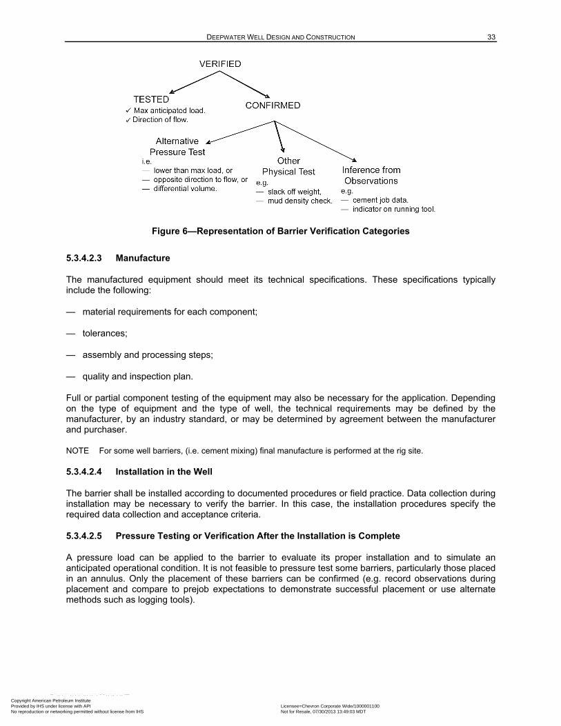
DEEPWATER WELL DESIGN AND CONSTRUCTION 33
Figure 6—Representation of Barrier Verification Categories
5.3.4.2.3 Manufacture
The manufactured equipment should meet its technical specifications. These specifications typically include the following:
— material requirements for each component;
— tolerances;
— assembly and processing steps;
— quality and inspection plan.
Full or partial component testing of the equipment may also be necessary for the application. Depending on the type of equipment and the type of well, the technical requirements may be defined by the manufacturer, by an industry standard, or may be determined by agreement between the manufacturer and purchaser.
NOTE For some well barriers, (i.e. cement mixing) final manufacture is performed at the rig site.
5.3.4.2.4 Installation in the Well
The barrier shall be installed according to documented procedures or field practice. Data collection during installation may be necessary to verify the barrier. In this case, the installation procedures specify the required data collection and acceptance criteria.
5.3.4.2.5 Pressure Testing or Verification After the Installation is Complete
A pressure load can be applied to the barrier to evaluate its proper installation and to simulate an anticipated operational condition. It is not feasible to pressure test some barriers, particularly those placed in an annulus. Only the placement of these barriers can be confirmed (e.g. record observations during placement and compare to prejob expectations to demonstrate successful placement or use alternate methods such as logging tools).
Copyright American Petroleum Institute Provided by IHS under license with API Licensee=Chevron Corporate Wide/1000001100
Not for Resale, 07/30/2013 13:49:03 MDTNo reproduction or networking permitted without license from IHS
--``,,`,````,``,`,``,,,`,,``,`-`-`,,`,,`,`,,`---
34 API RECOMMENDED PRACTICE 96
5.3.4.2.6 Operation
During continuing well operations, the ongoing effectiveness of some barriers may be monitored or reassessed. In some cases, the absence of pressure indicates that well control is maintained. While in other cases, an initial test can be repeated or an alternate test applied.
5.3.4.3 Verification by Pressure Testing
5.3.4.3.1 General
The most reliable verification of a physical barrier is to pressure test to the expected differential pressure in the direction of flow after the barrier is installed in the well.
It is practical to pressure test a newly installed mechanical barrier using the fluid that is in the well at the time of the installation. This fluid is typically the drilling mud, completion brine or water. Often regulations dictate the acceptance criteria for a pressure integrity test. Acceptance criteria (established by the well designer) may include:
— a pressure change during hold time;
— a visual observation of leak;
— a difference between pressure-up volume and bleed-back volume;
— a visual observation of fluid level.
NOTE It is good practice to conduct a low-pressure test (~200 psi or 300 psi) before a high-pressure test on mechanical components whose design allows their seal elements to be energized by the application of pressure.
5.3.4.3.2 Inflow Testing
An inflow test involves assessing integrity of a barrier system in the direction of flow from the formation into the wellbore. This typically involves replacing the hydrostatic barrier above the physical barrier to be inflow tested with a lighter hydrostatic fluid column and an operational barrier such as a BOP or test tool. This creates a managed net pressure load against the physical barrier in the direction of flow from the subsurface formations into the well. This can be accomplished by displacing some of the kill-weight fluid out from the well with lower density fluid(s). Refer to Annex C for examples of inflow testing scenarios.
To limit the quantity of kill-weight fluid displaced from the well and to create a trapped volume to test, the low density fluids are often displaced down a drill string and trapped by a temporary mechanical test barrier (e.g. packer, wellhead test plug, closed test rams, etc.) set above the physical barrier being tested. The temporary mechanical test barrier may serve as an additional well control barrier to replace the loss of the hydrostatic barrier during the inflow test. The ratings of all of the barriers (including the temporary mechanical test barrier) that will be exposed to the inflow net pressure during the inflow test should be considered.
In addition, the method by which the hydrostatic barrier will be reestablished at the conclusion of the inflow test, or in the event an anomaly is detected during the inflow test, should be considered. A contingency plan for reestablishing appropriate barriers should be prepared in case the barrier being tested does not pass the inflow test.
5.3.4.3.3 Alternatives to Inflow Testing
The verification method of conducting a full-differential pressure test in the direction of flow is not always feasible. The well designer may consider verifying the barrier using other physical evaluation methods.
Copyright American Petroleum Institute Provided by IHS under license with API Licensee=Chevron Corporate Wide/1000001100
Not for Resale, 07/30/2013 13:49:03 MDTNo reproduction or networking permitted without license from IHS
--``,,`,````,``,`,``,,,`,,``,`-`-`,,`,,`,`,,`---
DEEPWATER WELL DESIGN AND CONSTRUCTION 35
Barriers that are verified by methods other than a pressure test in the direction of flow are categorized as “confirmed.” Inflow testing alternatives may include the following.
⎯ Pressure test in the direction opposite of flow (if appropriate for the barrier).
⎯ Select a test pressure so that part of the barrier is exposed to the desired maximum pressure differential (also applies to a tubular string integrity test where the pressure load varies considerably over the length of the string).
⎯ Once a deep barrier has been verified by pressure testing, subsequent shallow barriers cannot be directly verified by holding a test pressure. In place of a stabilized test pressure, the total system pressure versus volume response can be used to verify a shallow barrier. Thus to verify subsequent barriers set shallower in the well, compare the volume required to be pumped to reach the test pressure for the deeper barrier to that when testing the shallower barrier. The volume required should decrease due to less volume of fluid being compressed.
⎯ Slack-off weight of string on a cement plug in a tubular to confirm that the plug has set or hardened as designed (acceptance criteria may involve applied weight and/or permitted penetration depth). This evaluation method will confirm that cement has set but not that it is a barrier to fluid flow.
⎯ Perform a drilling test of a cement plug by assessing the cement strength by the (high) weight on bit needed to drill the plug, or by the (slow) rate of penetration while drilling it, as a qualitative assessment of the cement barrier. The size of the cement plug may be increased to accommodate the length lost while performing the drilling test.
5.3.4.4 Verification of Hydrostatic Barriers
For a fluid column to serve as a barrier, the hydrostatic pressure of the fluid must exceed the pore pressure of the formation on which the pressure acts. Hydrostatic pressure is the pressure exerted by a fluid due to the vertical height and density of the fluid column. This requires a continuous fluid column of sufficient height to exceed the pore pressure. Failure to maintain the fluid column height may cause a pressure underbalance and allow the formation to flow.
Measure the density of the fluid and make adjustments, as necessary, to maintain the overbalance. The temperature profile of the well and the impact of temperature on fluid density should be considered. Pressure changes due to the dynamic effects of fluid movement arising from circulation or pipe movement should be considered. Further, where solids-laden fluids are used as hydrostatic barriers under static conditions, evaluate the effects of hole geometry (e.g. deviation, hole size, etc.) and exposure time on barrier effectiveness.
The drilling mud hydrostatic pressure from the height of the marine riser can be suddenly replaced with seawater hydrostatic pressure in an event where the LMRP is disconnected (i.e. a drift-off or drive-off scenario). This scenario can result in losing hydrostatic pressure (sufficient to maintain a barrier to the formation pressure). Thus, operational barriers must be in place to provide assurance that another physical barrier is rapidly established. For dynamically positioned rigs, an EDS is programmed to actuate the BOP and seal the wellbore with the BSRs when activated by the driller. In certain wells, a mud density can be used that maintains an overbalanced condition (even in the LMRP disconnection scenario). Refer to 8.2.2.1 for more information on riser margin.
NOTE If a fluid column contains some length of unset cement, any fluid below the top of cement (TOC) may lose pressure communication with the hydrostatic of the fluid above as the cement transitions from a liquid to a solid. The pressure exerted by a fluid volume that is located below a cement barrier can be more difficult to determine.
Copyright American Petroleum Institute Provided by IHS under license with API Licensee=Chevron Corporate Wide/1000001100
Not for Resale, 07/30/2013 13:49:03 MDTNo reproduction or networking permitted without license from IHS
--``,,`,````,``,`,``,,,`,,``,`-`-`,,`,,`,`,,`---
36 API RECOMMENDED PRACTICE 96
5.3.4.5 Verification of Annular Cement Barrier
For set cement in the annulus to serve as a physical barrier to the influx of formation fluids, the cement slurry shall be designed and laboratory-tested for the anticipated well conditions. The cement slurry should be placed in the well using recommended practices and equipment in accordance with API 65-2.
Successful placement of properly designed cement slurry can create a reliable annular barrier. However, verification of this barrier cannot be achieved through testing. Rather, it is confirmed using data collected during the slurry placement operation. If the data indicates that the cement top may not be at the planned depth or that the slurry placement has other problems, a diagnostic log may be used to establish the location of the cement top and/or evaluate the bond quality. Local regulations may specify alternative acceptance criteria or evaluation steps.
Exercise caution when using cement evaluation logs as the primary means of establishing the hydraulic competency of a cement barrier. The interpretation of cement evaluation logs is subjective. Refer to API 10TR-1 for an overview of the attenuation physics, features, and limitations of the various types of cement evaluation logs.
5.3.4.6 Assessment of Operational Barriers
Operational barriers include continuous monitoring of the well system, rapid recognition of evidence of an integrity upset, and effective execution of mitigation plans. By their nature, operational barriers cannot be tested like physical barriers. Testing shall be done to help assure that a physical barrier can be actuated when needed. Such tests include function testing on a periodic basis.
It is possible to certify personnel who have completed well control training, assign responsibilities for responding to a well control event, conduct drills to demonstrate readiness and proficiency, and retain records that demonstrate successful execution of institutional controls. Examples include well control certificates and records of operational drills.
5.3.5 Barrier Maintenance
Because any physical barrier can fail, the ongoing effectiveness of barriers is often assessed. The act of reassessing barrier performance is an operational barrier. Detection of a barrier failure normally results in immediate action to address the failure before continuing planned operations.
A retest of a physical barrier is the highest level of verification of the ongoing effectiveness of the barrier. Regulations often dictate the required retest frequency of equipment. The effectiveness of some barrier systems under operating conditions can be checked by inspection. An example of checking a barrier with in situ inspection is using a caliper log to measure the casing wall thickness (depending on tool type, this may be inferred from measuring casing internal diameter with a known outside diameter).
If a barrier fails, then reconsider the integrity of the overall well system, before continuing the current operation. Refer to local regulations for remedial actions for barrier failure. The following alternatives should be considered:
⎯ attempt to restore the barrier (i.e. repair/replace casing or hanger, repair BOPs, etc.);
⎯ install a different barrier (may be another barrier of the same type or a different type);
⎯ reconsider the overall system reliability based on the well’s forward plan;
⎯ create additional operational barriers.
The tables in Annex B provide examples of barrier assurance and barrier reestablishment if failure of a physical barrier occurs.
Copyright American Petroleum Institute Provided by IHS under license with API Licensee=Chevron Corporate Wide/1000001100
Not for Resale, 07/30/2013 13:49:03 MDTNo reproduction or networking permitted without license from IHS
--``,,`,````,``,`,``,,,`,,``,`-`-`,,`,,`,`,,`---
DEEPWATER WELL DESIGN AND CONSTRUCTION 37
5.4 Load Cases—Drilling and Completion Conditions
5.4.1 Tubular and Equipment Design Methodology
This section describes a common approach to how the well designer determines if a particular tubular string or hardware component (i.e. liner hanger, casing hanger, seal assembly, PBR, wellhead, BOP, float equipment, etc.) satisfies the requirements of the well application. The fundamental processes are similar for both casing and hardware components. Individual company designs can account for different loads and resistance by having varying inspection programs, operational limits, and practices. All processes are based on the tubular string design premise that the capacity exceeds expected loads. Each string builds on the previous, either isolating it from the internal load (long-string) or extending it (e.g. liner). The entire system shall be evaluated during well design to ensure a reliable, fit-for-purpose design.
The fundamental approach is to determine the following:
a) Determine the loads and the environment that the tubular string or component will experience throughout the well’s life.
NOTE The magnitude of the loads can vary during different stages of well construction and operation.
EXAMPLE Pressure loads on the casing and hardware are typically low during well construction. However, during production operations, the tubing and other completion components routinely sustain higher continuous pressure loads.
b) Establish the capacity of the tubular or component in the loading direction and its suitability under the environmental conditions (refer to 5.4.3).
c) Compare the loads to the capacities at the expected environmental conditions. The tubular or component is judged to be acceptable for the application if its capacity exceeds the anticipated load by an appropriate margin (design factor).
5.4.2 Loads
5.4.2.1 General
An operator designs a well for a given set of load conditions. Design load cases are based on individual company design standards, government regulations, component design and reliability considerations, local experience or field specific rules, operational considerations, and other factors. The internal loads are calculated and combined with the external loads to get the effective loads. The effective loads are compared with tubular or equipment ratings to ensure that the required design factors are met for their application. The design factor approach is used for well design because it is efficient and produces results with proven reliability.
To design casing, tubing, hardware and completion components, the well designer should use loads that represent expected load scenarios. Refer to Table 3 for examples of internal loads. During well construction, the design loads are short-duration and fit-for-purpose (e.g. partial well evacuation for collapse, deterministic kick volume for burst). During production operations, expected loads are of longer duration and expected (e.g. burst based on shut-in pressures, collapse based on depletion loads due to artificial lift, thermal loading during production or treating).
5.4.2.2 Internal Loads—MASP and MAWHP Determination
Maximum anticipated surface pressure (MASP) is a design load that represents the maximum internal pressure that may occur at the surface within each hole interval during the construction of the well. The internal pressure is typically defined by either an applied pressure or a reservoir pressure (subtracting the hydrostatic fluid/gas column). Examples of the methodology used to calculate MASP are shown in Table 3.
Copyright American Petroleum Institute Provided by IHS under license with API Licensee=Chevron Corporate Wide/1000001100
Not for Resale, 07/30/2013 13:49:03 MDTNo reproduction or networking permitted without license from IHS
--``,,`,````,``,`,``,,,`,,``,`-`-`,,`,,`,`,,`---
38 API RECOMMENDED PRACTICE 96
For DW wells, the maximum internal pressure at the subsea wellhead is called the maximum anticipated wellhead pressure (MAWHP). MAWHP for a DW well would be defined as the subsea wellhead pressure under MASP conditions. MASP and MAWHP vary only by the internal fluid/gas hydrostatic head pressure from the wellhead to the surface. The MAWHP is an internal pressure, and does not account for the effect of the external seawater gradient down to the wellhead.
This document only presents examples and leaves actual load case selection and definition to the operators. For example, MASP calculation methods (include, but are not limited to) the load cases described in Table 3.
5.4.2.3 External Loads
The pressure gradient that exists in the annulus behind each casing string depends on a variety of factors, and it can vary over the life cycle of the well. Immediately following cementing operations, the gradients are those of the drilling fluid, cement spacers, and liquid cement. However, complex changes can occur as the cement sets and the mud degrades. These changes should be considered in estimating the long-term backup resistance. The external pressure at the wellhead is based on a seawater gradient for DW wells.
Because of uncertainty in the annular pressure gradient over extended times (particularly within the cement column), assumptions may be made that represent a conservative case. Some time-dependent assumptions include the gradient of the drilling fluid above the TOC, which can partially degenerate (due to settling of the weight material) over time. The settling tendency of the weight material depends on fluid type, rheological properties, weight material characteristics and well conditions (i.e. temperature, geometry), and can be difficult to predict. In an open hole, the amount of gradient reduction is limited by the pore pressure. In a closed casing-by-casing annulus, the fluid gradient in the uppermost portion of the well can approach that of the base fluid.
For collapse design, use of the original mud gradient behind the casing should be considered (rather than using a partly or fully deteriorated mud gradient behind the casing) to avoid under-estimating the driving external collapse pressure.
The effective gradient in cement (assuming it is semiplastic as it sets and is capable of transmitting pressure) in the open hole will equal the pore pressure of the adjacent formation.
Less is known about the burst design backup provided by set cement within a casing-by-casing annulus (cement in the casing overlap or behind a tieback). Once cement becomes a solid, it no longer transmits fluid pressure. However, when burst pressures are applied to the pipe, the solid cement provides a mechanical backup, and the net loads on the tubular may be lower. Various models are available to estimate the structural contribution of the cement to the tubular burst resistance. An alternative approach is to use the cement mix-water density to define the backup fluid gradient for burst design calculations.
NOTE The settled weighting material may create a barrier in the annulus, restricting APB pressure relief to an uncemented open-hole interval below the previous shoe.
Refer to API 65-2 for further details about cementing.
Advanced design considerations may investigate the effect of point loading on collapse (such as where uneven stresses are applied through reservoir compaction, an active fault or salt movement).
Copyright American Petroleum Institute Provided by IHS under license with API Licensee=Chevron Corporate Wide/1000001100
Not for Resale, 07/30/2013 13:49:03 MDTNo reproduction or networking permitted without license from IHS
--``,,`,````,``,`,``,,,`,,``,`-`-`,,`,,`,`,,`---
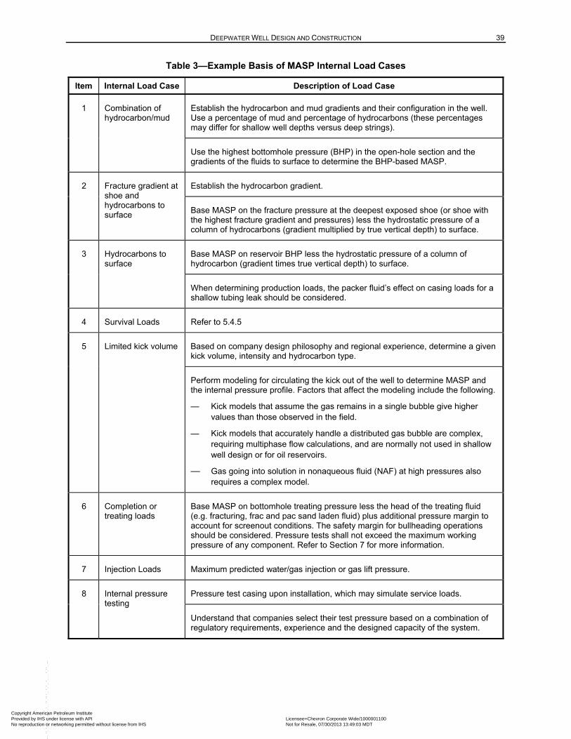
DEEPWATER WELL DESIGN AND CONSTRUCTION 39
Table 3—Example Basis of MASP Internal Load Cases
Item Internal Load Case Description of Load Case
1 Combination of hydrocarbon/mud
Establish the hydrocarbon and mud gradients and their configuration in the well. Use a percentage of mud and percentage of hydrocarbons (these percentages may differ for shallow well depths versus deep strings).
Use the highest bottomhole pressure (BHP) in the open-hole section and the gradients of the fluids to surface to determine the BHP-based MASP.
2 Fracture gradient at shoe and hydrocarbons to surface
Establish the hydrocarbon gradient.
Base MASP on the fracture pressure at the deepest exposed shoe (or shoe with the highest fracture gradient and pressures) less the hydrostatic pressure of a column of hydrocarbons (gradient multiplied by true vertical depth) to surface.
3 Hydrocarbons to surface
Base MASP on reservoir BHP less the hydrostatic pressure of a column of hydrocarbon (gradient times true vertical depth) to surface.
When determining production loads, the packer fluid’s effect on casing loads for a shallow tubing leak should be considered.
4 Survival Loads Refer to 5.4.5
5 Limited kick volume Based on company design philosophy and regional experience, determine a given kick volume, intensity and hydrocarbon type.
Perform modeling for circulating the kick out of the well to determine MASP and the internal pressure profile. Factors that affect the modeling include the following.
— Kick models that assume the gas remains in a single bubble give higher values than those observed in the field.
— Kick models that accurately handle a distributed gas bubble are complex, requiring multiphase flow calculations, and are normally not used in shallow well design or for oil reservoirs.
— Gas going into solution in nonaqueous fluid (NAF) at high pressures also requires a complex model.
6 Completion or treating loads
Base MASP on bottomhole treating pressure less the head of the treating fluid (e.g. fracturing, frac and pac sand laden fluid) plus additional pressure margin to account for screenout conditions. The safety margin for bullheading operations should be considered. Pressure tests shall not exceed the maximum working pressure of any component. Refer to Section 7 for more information.
7 Injection Loads Maximum predicted water/gas injection or gas lift pressure.
8 Internal pressure testing
Pressure test casing upon installation, which may simulate service loads.
Understand that companies select their test pressure based on a combination of regulatory requirements, experience and the designed capacity of the system.
Copyright American Petroleum Institute Provided by IHS under license with API Licensee=Chevron Corporate Wide/1000001100
Not for Resale, 07/30/2013 13:49:03 MDTNo reproduction or networking permitted without license from IHS
--``,,`,````,``,`,``,,,`,,``,`-`-`,,`,,`,`,,`---
40 API RECOMMENDED PRACTICE 96
5.4.2.4 Survival Design Considerations
Survival design scenarios can include extreme cases such as the complete loss of well control (blowout) from a well and reestablishing well control by installing a capping BOP stack. Extreme load scenarios are unlikely; however, it may be appropriate to consider loads that arise from these scenarios and to determine if the tubulars and equipment can survive the conditions. The well designer may adopt a philosophy of using different criteria for failure and different design factors. Tubular failure without the loss of life or damage to the environment may be considered. An example could be the collapse of a deep liner which does not result in hydrocarbon release to the mudline.
A capping stack may be used either to limit the flow from a well or to completely shut in the flow. If a complete loss of well control situation occurs, the highest collapse loads occur before the capping stack is installed. A cap and flow approach reduces the burst loads as compared to shutting in the well.
The capping stack may be a single ram, full BOP stack or other valve configuration. The additional bending loads exerted by the capping stack on the wellhead and structural pipe should be considered.
When designing for regular kick loads, the design criteria might be defined as the onset of yield, using minimum material properties, minimum measured wall thickness, and a design factor approaching 1.0. Alternatively, when determining tubular survival capability under extreme load conditions, the design criterion might be based on rupture capacity such as in API 5C3, using actual material properties and/or operator design practices based on advanced design methods or physical testing. Evaluate the entire system, including liner hangers, connections, and wellheads. Formulas for rupture in a nonsour environment are contained in API 5C3. Appropriate pipe performance guidance in sour environments is provided in 6.13.
NOTE An assumption inherent in putting a load scenario into a “survival” category is that while the tubulars or equipment may survive the load, the normal operability may be compromised by exposure to the survival load. Reassess the suitability of the well for continuing operations after a survival load situation occurs.
Examples of loads that might arise from survival scenarios for DW wells include the following.
EXAMPLE 1 Collapse loads during unintended flow: low back-pressure at the discharge location (surface or mudline) enables high flow rates and a low internal pressure profile compared with a typical hydrostatic column of drilling or completion fluid. The high flow rates of fluids at the reservoir temperature heat the wellbore, causing the fluids in the annuli to expand and possibly create additional pressure in the annulus. The pressures in the annuli increase because of this expansion, and collapse loads are increased.
EXAMPLE 2 Burst loads following cap and shut in: drilling casing design has always considered that a kick load may occur, and production casing design always considered that the tubing may leak; however, the maximum expected load is based on normal well control operations. Installing and closing or choking a capping stack after unintended flow may subject the exposed tubulars and equipment in the well to a full column of the production fluid with reservoir pressure at the source. At the mudline, this is known as the mudline shut-in pressure. The resulting burst load scenario also includes a high temperature arising from the warm flow when the capping stack valves are initially closed and transitioning to the geothermal temperature when the flow is stopped and the heat dissipates. A combination of internal pressure and cool temperature increases the tension load on tubulars, particularly at the top of the well.
EXAMPLE 3 Axial forces; unconstrained flow will raise the wellbore temperature at the mudline which will reduce tension loads and possibly create compression loads and upward forces on the wellhead hangers. These compression loads should be addressed.
Copyright American Petroleum Institute Provided by IHS under license with API Licensee=Chevron Corporate Wide/1000001100
Not for Resale, 07/30/2013 13:49:03 MDTNo reproduction or networking permitted without license from IHS
--``,,`,````,``,`,``,,,`,,``,`-`-`,,`,,`,`,,`---
DEEPWATER WELL DESIGN AND CONSTRUCTION 41
5.4.3 Capacity (Resistance)
5.4.3.1 General
The first step in determining capacity is to define the rating basis within the context of the well application. A common example design criterion is the onset of yield. An example of a more extreme design criterion is the loss of structural integrity. To allow for the potential variance in material properties, common assumptions include using the minimum yield stress (MYS) that meets the material specification and using the minimum geometry defined by the dimensional tolerances (wall thickness). The designer should determine capacity in accordance with the expected loads (accounting for multiaxial effects where applicable).
5.4.3.2 Uniaxial
Burst and tensile loads assume failure will occur due to stresses exceeding the yield strength of the material.
Refer to API 5C3 for approaches to calculating collapse strength. Collapse capacity in relatively thin-wall tubulars can be governed by geometric instability rather than by hoop stresses that approach yield stress.
5.4.3.3 Triaxial
Refer to API 5C3 for a triaxial yield calculation that determines the initial yielding of the tubular under multiaxial load conditions.
5.5 Tubing Design
5.5.1 Completion Tubing/Work String Load and Design Consideration
All components in the completion, (e.g. tubing, drill pipe, connections, packers, PBR, seals, nipples, mandrels, SCSSV, plugs) should be designed for the anticipated life-of-well service conditions.
Considerations for completion tubing and work string design should include the following.
— Design the production tubing with consideration for the loads associated with anticipated completion, production and workover activities, and that the design is fit for field development purposes.
— Investigate the most highly loaded and weak points throughout the tubing and work strings for burst, collapse, tensile, and compression strength (e.g. below the tubing hanger, at the production packer, and cross-overs throughout the string).
— The subsea completion tubing strings can be fixed to a production packer or have a seal assembly that can be inserted into a PBR above or below the production packer. The change in axial loads on the production packer or movement of the seals in the PBR should be considered.
Documenting the design requirements and design loads for completion tubing components and work strings should be considered. This should include completion tubing procurement, maintenance, and preparation, as well as installation/workover operations. Provide documentation to meet local regulatory requirements.
Inclusion of the following steps during the design process should be considered.
⎯ Establish possible conceptual completion tubing string designs for the well after compiling the key well data and perform a first pass risk assessment for review with all stakeholders.
Copyright American Petroleum Institute Provided by IHS under license with API Licensee=Chevron Corporate Wide/1000001100
Not for Resale, 07/30/2013 13:49:03 MDTNo reproduction or networking permitted without license from IHS
--``,,`,````,``,`,``,,,`,,``,`-`-`,,`,,`,`,,`---
42 API RECOMMENDED PRACTICE 96
⎯ The use of system analysis (i.e. inflow/outflow performance) software to verify that the conceptual completion tubing design(s) are able to accommodate the anticipated flow performance for the well.
The conceptual design should account for the following items.
⎯ Flow rate and pressure drop are acceptable.
⎯ Fluid velocities are below erosional velocity. (Refer to API 14E for information about erosional velocity for carbon steel in a corrosive environment. Design the tubing metallurgy to handle the anticipated erosional and/or corrosion environment)
⎯ Tubing size considers the flow regimes anticipated throughout the well’s life (e.g. to minimize slugging or to provide minimum velocities to unload liquids in a gas well).
A detailed well design (e.g. casing size, casing set points or cement tops) shall be established that will accommodate the selected completion tubing string and work string concept. Temperature and pressure profiles may be developed along the depth of the completion string(s) during different well operations. The stresses can be calculated considering:
⎯ temperature change effects,
⎯ pressure differential effects, and
⎯ axial loading (e.g. due to plugs, packers, PBRs, buckling, ballooning, etc.).
The computed stresses are compared to the mechanical properties of the completion components at their installed depths. The change in axial loads on the production packer or movement of seals in the PBR should be considered. When comparing the design stresses to the selected tubular material load capacities, the following criteria should be considered:
⎯ burst and tensile loads assume failure will occur due to stresses exceeding the yield strength of the material;
⎯ the tubing design is based upon uniaxial, biaxial, or triaxial analysis. Triaxial design is the most common design method used for tubing design.
NOTE Collapse capacity in relatively thin-wall tubulars can be governed by geometric instability rather than by hoop stresses that approach yield stress.
Refer to API 5C3 for approaches to calculating collapse strength and to API 5C5 for more information about geometric instability.
5.5.2 Data Collection
Use the data in Table 4 that is relevant when developing a completion tubing/work string load evaluation and design.
5.5.3 Load Cases
Table 5 and Table 6 are general descriptions of load cases that may occur in a given well. As with casing, tubing load scenarios include internal and external pressure, temperature, tension, etc. Section 7 discusses more detailed aspects of completion design to consider when evaluating loads for production casing, tubing string and work string.
Copyright American Petroleum Institute Provided by IHS under license with API Licensee=Chevron Corporate Wide/1000001100
Not for Resale, 07/30/2013 13:49:03 MDTNo reproduction or networking permitted without license from IHS
--``,,`,````,``,`,``,,,`,,``,`-`-`,,`,,`,`,,`---
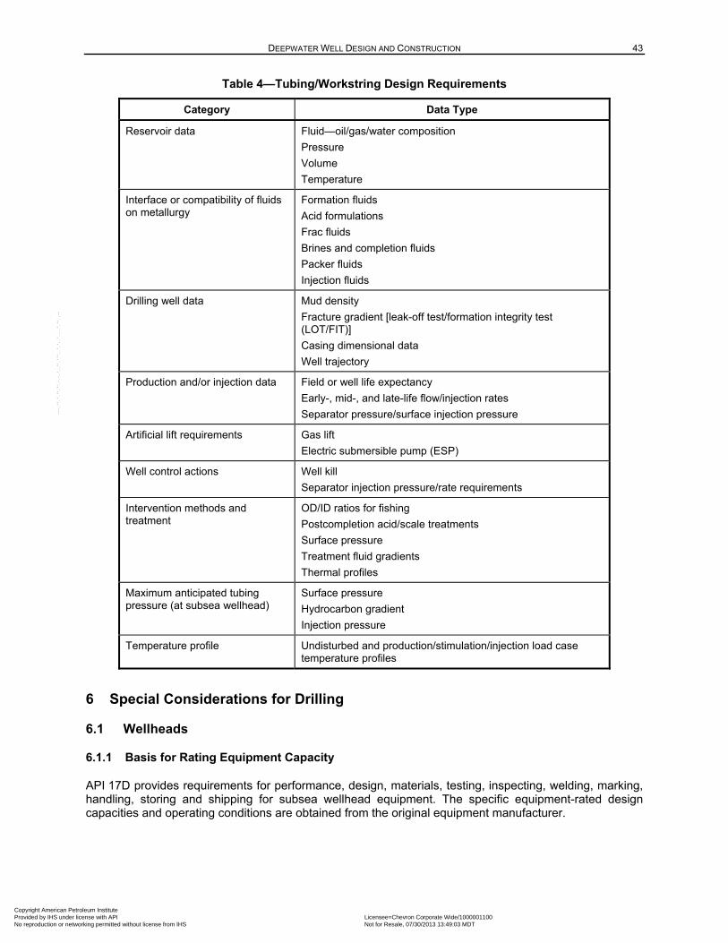
DEEPWATER WELL DESIGN AND CONSTRUCTION 43
Table 4—Tubing/Workstring Design Requirements
Category Data Type
Reservoir data Fluid—oil/gas/water composition
Pressure
Volume
Temperature
Interface or compatibility of fluids on metallurgy
Formation fluids
Acid formulations
Frac fluids
Brines and completion fluids
Packer fluids
Injection fluids
Drilling well data Mud density
Fracture gradient [leak-off test/formation integrity test (LOT/FIT)]
Casing dimensional data
Well trajectory
Production and/or injection data Field or well life expectancy
Early-, mid-, and late-life flow/injection rates
Separator pressure/surface injection pressure
Artificial lift requirements Gas lift
Electric submersible pump (ESP)
Well control actions Well kill
Separator injection pressure/rate requirements
Intervention methods and treatment
OD/ID ratios for fishing
Postcompletion acid/scale treatments
Surface pressure
Treatment fluid gradients
Thermal profiles
Maximum anticipated tubing pressure (at subsea wellhead)
Surface pressure
Hydrocarbon gradient
Injection pressure
Temperature profile Undisturbed and production/stimulation/injection load case temperature profiles
6 Special Considerations for Drilling
6.1 Wellheads
6.1.1 Basis for Rating Equipment Capacity
API 17D provides requirements for performance, design, materials, testing, inspecting, welding, marking, handling, storing and shipping for subsea wellhead equipment. The specific equipment-rated design capacities and operating conditions are obtained from the original equipment manufacturer.
Copyright American Petroleum Institute Provided by IHS under license with API Licensee=Chevron Corporate Wide/1000001100
Not for Resale, 07/30/2013 13:49:03 MDTNo reproduction or networking permitted without license from IHS
--``,,`,````,``,`,``,,,`,,``,`-`-`,,`,,`,`,,`---
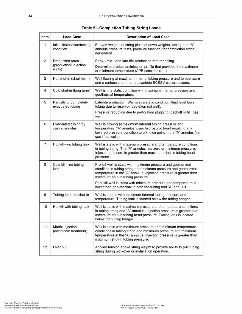
44 API RECOMMENDED PRACTICE 96
Table 5—Completion Tubing String Loads
Item Load Case Description of Load Case
1 Initial installation/testing condition
Buoyed weights of string plus set down weights, tubing and “A” annulus pressure tests, pressure function) for completion string equipment.
2 Production rates—(production/ injection wells)
Early-, mid-, and late-life production rate modeling.
Determine production/injection profile that provides the maximum or minimum temperature (APB consideration).
3 Hot shut-in (short term) Well flowing at maximum internal tubing pressure and temperature and a surface shut-in or a downhole SCSSV closure occurs.
4 Cold shut-in (long term) Well is in a static condition with maximum internal pressure and geothermal temperature.
5 Partially or completely evacuated tubing
Late-life production. Well is in a static condition; fluid level lower in tubing due to reservoir depletion (oil well).
Pressure reduction due to perforation plugging, packoff or fill (gas well).
6 Evacuated tubing by casing annulus
Well is flowing at maximum internal tubing pressure and temperature. “A” annulus loses hydrostatic head resulting in a lowered pressure condition to a known point in the “A” annulus (i.e. gas lifted wells).
7 Hot kill—no tubing leak Well is static with maximum pressure and temperature conditions in tubing string. The “A” annulus has zero or minimum pressure. Injection pressure is greater than maximum shut-in tubing head pressure.
8 Cold kill—no tubing leak
Pre-kill-well is static with maximum pressure and geothermal condition in tubing string and minimum pressure and geothermal temperature in the “A” annulus. Injection pressure is greater than maximum shut-in tubing pressure.
Post-kill-well is static with minimum pressure and temperature is lower than geo-thermal in both the tubing and “A” annulus.
9 Tubing leak hot shut-in Well is shut-in with maximum internal tubing pressure and temperature. Tubing leak is located below the tubing hanger.
10 Hot kill with tubing leak Well is static with maximum pressure and temperature conditions in tubing string and “A” annulus. Injection pressure is greater than maximum shut-in tubing head pressure. Tubing leak is located below the tubing hanger.
11 Matrix injection (acid/scale treatment)
Well is static with maximum pressure and minimum temperature conditions in tubing string and maximum pressure and minimum temperature in the “A” annulus. Injection pressure is greater than maximum shut-in tubing pressure.
12 Over pull Applied tension above string weight to provide ability to pull tubing string during workover or installation operation.
Copyright American Petroleum Institute Provided by IHS under license with API Licensee=Chevron Corporate Wide/1000001100
Not for Resale, 07/30/2013 13:49:03 MDTNo reproduction or networking permitted without license from IHS
--``,,`,````,``,`,``,,,`,,``,`-`-`,,`,,`,`,,`---
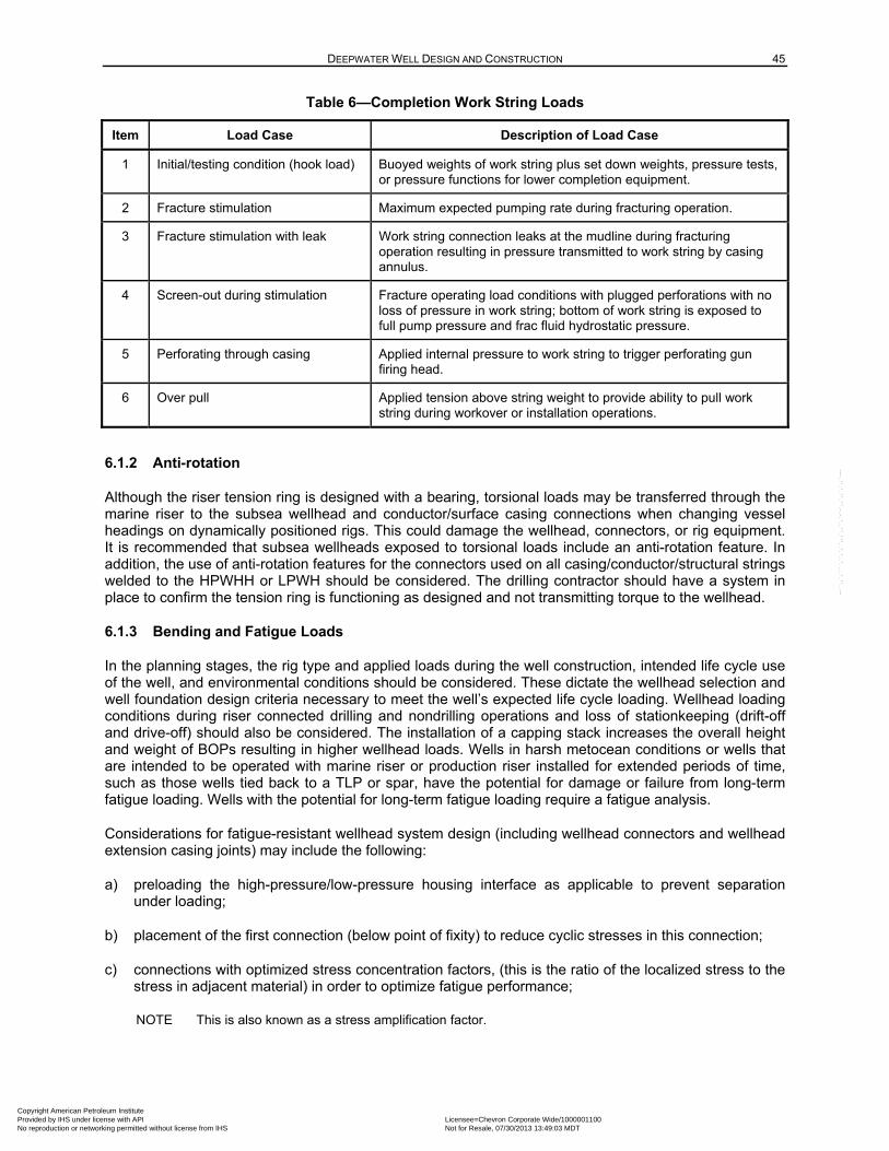
DEEPWATER WELL DESIGN AND CONSTRUCTION 45
Table 6—Completion Work String Loads
Item Load Case Description of Load Case
1 Initial/testing condition (hook load) Buoyed weights of work string plus set down weights, pressure tests, or pressure functions for lower completion equipment.
2 Fracture stimulation Maximum expected pumping rate during fracturing operation.
3 Fracture stimulation with leak Work string connection leaks at the mudline during fracturing operation resulting in pressure transmitted to work string by casing annulus.
4 Screen-out during stimulation Fracture operating load conditions with plugged perforations with no loss of pressure in work string; bottom of work string is exposed to full pump pressure and frac fluid hydrostatic pressure.
5 Perforating through casing Applied internal pressure to work string to trigger perforating gun firing head.
6 Over pull Applied tension above string weight to provide ability to pull work string during workover or installation operations.
6.1.2 Anti-rotation
Although the riser tension ring is designed with a bearing, torsional loads may be transferred through the marine riser to the subsea wellhead and conductor/surface casing connections when changing vessel headings on dynamically positioned rigs. This could damage the wellhead, connectors, or rig equipment. It is recommended that subsea wellheads exposed to torsional loads include an anti-rotation feature. In addition, the use of anti-rotation features for the connectors used on all casing/conductor/structural strings welded to the HPWHH or LPWH should be considered. The drilling contractor should have a system in place to confirm the tension ring is functioning as designed and not transmitting torque to the wellhead.
6.1.3 Bending and Fatigue Loads
In the planning stages, the rig type and applied loads during the well construction, intended life cycle use of the well, and environmental conditions should be considered. These dictate the wellhead selection and well foundation design criteria necessary to meet the well’s expected life cycle loading. Wellhead loading conditions during riser connected drilling and nondrilling operations and loss of stationkeeping (drift-off and drive-off) should also be considered. The installation of a capping stack increases the overall height and weight of BOPs resulting in higher wellhead loads. Wells in harsh metocean conditions or wells that are intended to be operated with marine riser or production riser installed for extended periods of time, such as those wells tied back to a TLP or spar, have the potential for damage or failure from long-term fatigue loading. Wells with the potential for long-term fatigue loading require a fatigue analysis.
Considerations for fatigue-resistant wellhead system design (including wellhead connectors and wellhead extension casing joints) may include the following:
a) preloading the high-pressure/low-pressure housing interface as applicable to prevent separation under loading;
b) placement of the first connection (below point of fixity) to reduce cyclic stresses in this connection;
c) connections with optimized stress concentration factors, (this is the ratio of the localized stress to the stress in adjacent material) in order to optimize fatigue performance;
NOTE This is also known as a stress amplification factor.
Copyright American Petroleum Institute Provided by IHS under license with API Licensee=Chevron Corporate Wide/1000001100
Not for Resale, 07/30/2013 13:49:03 MDTNo reproduction or networking permitted without license from IHS
--``,,`,````,``,`,``,,,`,,``,`-`-`,,`,,`,`,,`---
46 API RECOMMENDED PRACTICE 96
d) an enhanced subsea production tree connector for appropriate strength and fatigue performance;
e) special care in the quality of welds [includes: preparation, application, welding materials, postwell heat treating processes, and final surface preparation (for both fatigue resistance and enhanced inspection quality)];
f) properties are appropriate for fatigue resistance;
g) special inspection criteria for weld or materials to minimize the potential for defects that could become crack initiation sites.
6.2 Casing Hanger/Seal Assembly Lockdown to Subsea Wellhead Systems
6.2.1 General
The casing strings in DW wells can be exposed to thermal and pressure conditions during the construction and operation of a well, which can cause subsea casing hangers/seal assemblies to lift off the landing seat. Movement in the subsea casing hanger/seal assembly can be detrimental to the ability of the seal assembly to hold pressure.
To minimize or prevent movement of the seal assembly, the subsea casing hanger shall be locked to the wellhead. To accomplish this, the casing hanger seal assembly components shall include a feature that prevents upward movement of the casing hanger and seal assembly.
Performing an analysis of the forces on the casing hanger caused by thermal growth of the casing and the pressure differential loads across the seal assembly should be considered, to include elements such as
— assessing the potential for casing hanger/seal assembly movement,
— determining the lock down force necessary to keep the casing hanger in place, and
— verifying the rating of the lockdown component is greater than the predicted necessary lockdown force.
The installation of supplemental lockdown subs or bushings above the casing hanger/seal assembly should be considered for cases
— when the upward loading conditions of the casing string anticipated from the thermal and annulus pressure effects can exceed the rating of the seal assembly lock-ring, or
— when repeated movement of the seal assembly from thermal cycling during long-term production service may cause degradation of the seal integrity.
For some manufacturers, these lockdown subs or bushings may provide greater lockdown capacity than that available from lockdown features integral to a seal assembly. However, the lockdown capacity of the integral seal assembly, lockdown and a supplemental casing hanger lockdown bushing may not be additive. In this case, the lockdown capacity of a single device provides the locking capacity for the well.
The locking down of the casing hanger shall occur prior to exposure to any well operations that could result in thermal or pressure loading that would cause the casing hanger to lift off seat. Local regulations may require that when the casing hanger is landed in the HPWHH, it shall be locked down to the wellhead when installed or as the immediate next step.
Copyright American Petroleum Institute Provided by IHS under license with API Licensee=Chevron Corporate Wide/1000001100
Not for Resale, 07/30/2013 13:49:03 MDTNo reproduction or networking permitted without license from IHS
--``,,`,````,``,`,``,,,`,,``,`-`-`,,`,,`,`,,`---
DEEPWATER WELL DESIGN AND CONSTRUCTION 47
6.2.2 Casing Hanger Seal Assembly Verification
Casing hanger seal assemblies are designed to provide bidirectional sealing capability. An installed seal assembly is confirmed by being alternatively pressure tested from above the hanger. The water depth may limit the pressure differential required by an inflow test to verify the barrier as a tested barrier. The upper-most casing hanger seal assembly will be inflow tested during well abandonment operations. The assurance of the seal effectiveness from below is based on design and validation testing for the equipment, quality assurance (QA), correct installation and pressure testing from above. After verifying proper installation and a successful pressure test, the seal assembly can be considered a confirmed barrier.
Casing hanger seal assembly designs are qualification tested following the requirements established in API 17D. This includes:
— testing at the rated pressure and temperature extremes, and
— load testing of the casing hanger/seal assembly lockdown.
The seal in the hanger is a barrier in the annulus flow path, and its proper landing shall be confirmed using manufacturer recommended procedures. For example, manufacturers may provide lead impression blocks or shear pins on the running tool to confirm that the seal assembly was installed and positioned properly relative to the hanger.
6.2.3 Wellhead Corrosion Prevention
Corrosion can occur over the life of a well (whether a short duration exploration well, a multiyear production well, or an injection well). Corrosion protection is provided in the following areas:
— subsea wellhead inner and outer surfaces are protected by corrosion-preventative fluids and/or coatings such as zinc or manganese phosphate or a fluoropolymer; inner surfaces may also be protected by corrosion-preventative fluids and inhibited drilling/completion fluids;
— wellhead seal preparations (ring gasket area) are overlaid with a corrosion-resistant alloy for corrosion protection. Consideration should be given to overlaying other seal areas of the wellhead.
The expected corrosive conditions over the life of the well and how they affect external surfaces should be considered. Subsea wellhead surfaces can be protected by coating or cathodic protection. The effect of temporary or permanent guide bases installed on a well intended for production service should be considered. Corrosion effects can be mitigated through the quality of the installation method and the paint applied to the structural casing or guide bases and/or the number and type of anodes that can be installed on the wellhead or guide bases. If anodes are installed on the guide bases to protect the wellhead and guidebase, provide an electrical connection between the guide base and low pressure housing and structural casing. For further long-term protection of a wellhead, attaching an anode “sled” to the wellhead to supplement initial corrosion protection methods should be considered.
6.2.4 Subsea Wellhead Ring Gasket
A ring gasket provides the seal between the subsea wellhead and BOP connector or subsea production tree connector. Some wellhead designs include a secondary independent sealing surface in case the primary sealing surface is damaged. Special ring gaskets are available to seal on the secondary sealing surface. Ring gaskets that provide a metal-to-metal seal are recommended for normal service. The normal requirement is for the gasket to seal against internal pressure. However, under specific conditions, sealing against external pressure can be required of the gasket such as during inflow testing or during production operations. The effect of external versus internal pressure on the gasket should be considered in determining whether a proper gasket type is specified or other contingencies are planned.
Copyright American Petroleum Institute Provided by IHS under license with API Licensee=Chevron Corporate Wide/1000001100
Not for Resale, 07/30/2013 13:49:03 MDTNo reproduction or networking permitted without license from IHS
--``,,`,````,``,`,``,,,`,,``,`-`-`,,`,,`,`,,`---
48 API RECOMMENDED PRACTICE 96
For long-term production service, review the material composition of the ring gasket and inlay on the wellhead and wellhead connector to avoid galvanic corrosion issues.
6.2.5 Wellhead Growth
6.2.5.1 General
Wellhead growth is the term used for axial movement of the wellhead relative to its initial position at the mudline. Wellhead growth is caused by the forces exerted on the wellhead by:
— thermal expansion/contraction of tubulars tied back to the wellhead and subsidence, and
— increasing pressure within the annuli created between the tubulars
The changes in tubular forces and increase in annular pressure can be caused by the thermal effects of increased temperature during production or drilling deeper. Water or gas injection can decrease temperatures.
Changes in temperature from initial installed conditions will cause thermal stresses in the well casing. The casing strings tied back to the wellhead are constrained axially at the TOC and at the wellhead. The temperature increase from production or additional drilling will elongate the steel casing and attempt to make the HPWHH move axially upward relative to the LPWH. If the HPWHH is locked to the LPWH, this axial constraint will cause a compressive force to be generated within the casing.
Increased wellbore temperatures during production or drilling also causes the expansion of fluids in the annuli between well tubulars. If these annuli are trapped, the annulus volume remains nearly constant and the fluid expansion is expressed as a pressure increase. The pressure increase is isotropic and acts on the underside of the casing hangers, as well as on the tubulars. The effect of the compressive stresses in individual tubulars and pressures in the annuli exerts an upward force on the wellhead. If the surface casing (attached to the HPWHH) is not cemented all the way to the mudline, then the HPWHH can move, relative to the LPWH (if not latched together), rising above its initial position at the mudline. The axial forces that can act on the locking mechanism between the LPWH and HPWHH shall be considered when choosing the rating of the locking mechanism.
The amount of axial movement is calculated as the amount that balances all forces on the wellhead and strains in the uncemented parts of the casing strings. The constraint that enables a solution to the calculation is that all tubular strings have the same displacement at the wellhead because the hangers remain in the same location relative to each other (if a hanger is not axially restrained, there can be significant additive forces acting on the lock down mechanism of the adjacent hanger).
6.2.5.2 Key Inputs
Examples of the key inputs used to predict wellhead growth are the cement tops for the casing strings (defines the amount of strain possible in each string), applied tension, and the production temperature condition (defines the temperature change from the initial conditions that causes thermal stresses and annulus fluid expansion).
6.2.5.3 Effects
If wellhead growth occurs, it can affect subsea equipment such as the flow line or umbilical. Conversely, wellhead subsidence can result in decreased tension on subsea hangers.
Copyright American Petroleum Institute Provided by IHS under license with API Licensee=Chevron Corporate Wide/1000001100
Not for Resale, 07/30/2013 13:49:03 MDTNo reproduction or networking permitted without license from IHS
--``,,`,````,``,`,``,,,`,,``,`-`-`,,`,,`,`,,`---
DEEPWATER WELL DESIGN AND CONSTRUCTION 49
6.3 Structural Casing
6.3.1 General
Structural casing, normally in conjunction with the next fully cemented string, provides the foundation for a DW well and is designed and installed with the necessary structural capacity to withstand the expected loads. Two primary loads on structural casing are axial or bearing load and bending loads.
6.3.2 Axial Loads
Installation methods impact the axial capacity of a structural casing. In DW well construction, the most common method of installing structural casing is jetting due to the soft sediments generally encountered near the mudline. If hard sediments or boulders are present then structural casing is installed by drilling and then grouting, similar to a conventional casing string. In more rare cases, the structural casing is installed by driving using a subsea hammer, similar to platform installations in shallow water. The method of installation impacts the initial and time-dependent development of axial capacity of the structural casing. Of these methods, jetting causes the greatest degradation in axial capacity and, if the structural casing is not designed and installed properly, there is potential for the casing to settle and fail under axial load.
The jetted structural casing is initially required to support its own weight. If it is installed via drilling and grouting, a temporary guide base or mud mat may be used to support the weight of the string. If the structural casing can support its own weight and the weight of the next casing string, the wait-on-cement time for mechanical strength development required to resist settling can be eliminated.
After the first riserless casing string is cemented to the mudline and the cement has set, the axial load for the remainder of the well including all casings and the BOPs are supported by the combined capacity of these two casing strings. The load that a given string can carry depends not only on its axial resistance, but also the degree of which the load is transferred to the surrounding formations. This can depend on the installation method and how well it is executed. Axial capacity is dependent on soil strength and the disturbance of the soil as the structural casing is jetted into place. The amount of disturbance depends on the rate of jetting (pumping), the degree to which the connector’s OD exceeds the casing OD, and the time allowed for the soil to recover from the jetting operation. Externally flush connectors can improve skin friction development due to fewer disturbances. If there are questions about the axial capacity of the well due to cementing uncertainty (after first running the BOPs, before drilling ahead), performing a “slump” (subsidence) test should be considered. This can simulate the loads imposed by the BOP stack (excluding the LMRP) and a capping stack. A slump test can be performed by reducing riser tension. Refer to API 2A-WSD for the methodology for establishing the axial capacity of piles.
6.3.3 Marine-riser-induced Bending Loads
The structural casing is designed to withstand the expected bending moments imposed during the well’s life cycle. The most severe bending loads occur during well construction as a result of loads imposed by the rig and marine riser system. Bending loads applied by the marine riser are a function of the height of the LMRP flex joint above the mudline, riser tension, and maximum angle of the flex joint. A marine riser and structural casing design analysis considers these factors (e.g. metocean conditions, vessel offsets, BOP stack and mud weight).
Considerations that affect structural casing bending loads include the following.
a) The bending moment and shear force increase below the mudline and reach a maximum at a distance of 5 to 30 pipe diameters below the mudline, depending on soil strengths. The bending moment and shear force decrease below the maximum point and reduce to zero at depth.
b) The higher the HPWHH (affecting the height of the flex joint) is from the mudline, the lower the bending moment is on the hydraulic connector and HPWHH, while the structural casing bending moment is increased.
Copyright American Petroleum Institute Provided by IHS under license with API Licensee=Chevron Corporate Wide/1000001100
Not for Resale, 07/30/2013 13:49:03 MDTNo reproduction or networking permitted without license from IHS
--``,,`,````,``,`,``,,,`,,``,`-`-`,,`,,`,`,,`---
50 API RECOMMENDED PRACTICE 96
c) Wellheads, structural casing, conductor, pipe body, and casing connectors are designed to accommodate bending moments and shear forces.
d) Wellhead and structural casing deflection when the drilling riser is removed.
e) The additional bending load that can result from the installation of a capping stack. This weight, combined with the BOPs, will likely be the highest possible free standing load.
f) The maximum mud weight expected in the well, as it will affect the minimum required riser tension.
g) The type of rig positioning system (i.e. dynamically positioned or moored) and water depth, as both will affect the maximum angle of the flex joint.
h) Deep currents near the mudline can increase bending moment loads.
i) Soil strength effects on wellhead deflection and bending moment loads.
j) Trawler snag loads for bending calculations (depending on area and depth of water).
NOTE The worst case load scenario is that of failure to disconnect the LMRP with the loss of station (e.g. drive-off under power, or drift-off under environmental loads without disconnecting). Performing a riser failure analysis (also known as a weak point analysis) should be considered to confirm that a loss of pressure integrity below the BOP stack will not occur in this situation.
6.3.4 Subsea Tree and Flow Line Induced Bending Loads
During completion execution, either a tubing spool or a horizontal tree may be attached to the subsea wellhead. This increases the height from the mudline to the flex joint on the BOPs. The increase in height increases bending loads when compared to a drilling-only case.
Additionally, the loads applied when pulling in a pipeline/flowline should be considered. This exerts a horizontal load that can create significant bending moments. The deflection of the wellhead due to BOP load may need to be considered for the wellhead stiffness or flowline flexibility.
6.4 Riserless Mudline Hangers and Submudline Hangers
6.4.1 Riserless Mudline Hangers
Open water conductor strings may be installed and serve the following purposes:
— isolation of shallow hazards;
— additional support for structural casing when in soft soil conditions or when very heavy surface casing loads are expected.
The mudline hanger has several variations with the seal-when-landed type being the most common. Mud circulation, after the hanger is landed for this configuration, is accomplished by opening and closing ball valves below the hanger with the ROV. Therefore the hanger profile is placed in the outer structural casing above the mudline to allow for ball valve access. Alternatives include not landing the hanger until the cement is pumped or use of an alternative shifting mechanism to allow for the placement of cement.
6.4.2 Submudline Hangers run through the 18 3/4-in. BOP
The constraints imposed by the commonly used 18 3/4-in. BOP and HPWHH can present well design challenges with regard to both the number and size of casing strings that can be run. The HPWHH is installed on surface casing. The minimum ID sets the maximum diameter for subsequent strings. DW
Copyright American Petroleum Institute Provided by IHS under license with API Licensee=Chevron Corporate Wide/1000001100
Not for Resale, 07/30/2013 13:49:03 MDTNo reproduction or networking permitted without license from IHS
--``,,`,````,``,`,``,,,`,,``,`-`-`,,`,,`,`,,`---
DEEPWATER WELL DESIGN AND CONSTRUCTION 51
wells routinely require more strings of casing than can be accommodated within the HPWHH. DW well considerations such as the narrow margin between the pore and fracture pressures, ultimate well depth, subsurface geology and geohazards all add to the total number of casing strings required during well construction. Submudline hangers provide additional positions from which to hang the heavy large diameter strings needed to reach deep objectives when geologic conditions are difficult.
Some liners (e.g. 18 in. and/or 16 in.) are landed in submudline hanger profiles to preserve the hanger profiles in the wellhead housing for the critical intermediate and production casing strings. These profiles are installed in the surface casing string when it is run. This configuration means that surface casing between the high pressure housing and the submudline hanger profiles can be exposed to higher loads than those for surface casing installed in land or platform wells.
The submudline liner is designed like any other casing string in a DW well. However, the hanger is landed submudline, which adds complexity. The pipe between the HPWHH and the submudline hanger is typically dual-submerged arc welded pipe which is normally built to line pipe specifications. Large OD connectors may be welded to the pipe, requiring welding procedures, weld qualifications, and weld testing for applications approaching yield strength. For the section of pipe between the hanger and HPWHH, the fatigue loads at the top of the pipe from BOP movement, and while running this casing open water, should be considered.
Some submudline hangers/seal systems have lock down features. When well conditions (hydrocarbon exposure/temperature loads) warrant, locking down the submudline hanger(s) or an alternative method (e.g. cement placement) should be considered to prevent thermal growth and loss of seal integrity.
The use of a quality plan provides additional assurance that the hanger components are manufactured to correct tolerances from materials having the mechanical and chemical properties required to meet the design performance specifications.
6.5 Cemented Shoe Track System
A cemented shoe track is a discrete section of the bottom of a casing or liner string designed to contain a small volume of cement from the end of the primary cement job (refer to API 65-2). Purposes of the shoe track are the following.
a) To improve the cement quality in the annulus immediately outside the cemented shoe. Mud and cement contamination (at the end of a cement displacement due to the mud film dislodged ahead of a top cement wiper plug or during an inner string cement job) is captured in the shoe track.
b) To allow the primary cement to be displaced into the annulus and then trapped and held static while the cement sets. U-tubing can occur by due to the difference between the higher density cement in the annulus and the lower density displacement fluid inside the casing, resulting in a hydrostatic pressure imbalance at the casing shoe. Flow from the annulus into the casing is prevented by float valves in the shoe track.
c) To allow a positive indication when the top plug bumps during the cement job indicating the expected cement displacement volume has been achieved.
d) To allow a pressure test of the casing once the cement is in place (but prior to setting). The top cement wiper plug, (once landed on a landing collar, float collar, or bottom plug) provides a pressure seal (within the equipment rating) from above.
e) A properly designed cemented shoe track may also serve as a physical barrier once the cement has set. Because of the functionality of the mechanical components used to construct a typical shoe track (e.g. float valves, wiper plugs), it is difficult to verify the shoe track cement as an effective physical barrier, by either pressure testing or inflow testing. This is not typically an issue during the course of
Copyright American Petroleum Institute Provided by IHS under license with API Licensee=Chevron Corporate Wide/1000001100
Not for Resale, 07/30/2013 13:49:03 MDTNo reproduction or networking permitted without license from IHS
--``,,`,````,``,`,``,,,`,,``,`-`-`,,`,,`,`,,`---
52 API RECOMMENDED PRACTICE 96
the well construction, as once the cement has set, the shoe track is normally drilled out when starting the subsequent drilling phase.
However, during well abandonment, the cemented shoe track system may be included as one of the barriers designed to prevent flow up the casing or liner. The shoe track system should never be treated as multiple barriers based on the presence of cement and mechanical float valves regardless of pressure testing or inflow testing results because:
— a pressure test can be successfully achieved with contaminated cement in the shoe track due to the seal provided by the top cement wiper plug landed on a landing collar or float collar;
— an inflow test can be successfully achieved with contaminated cement in the shoe track due to the presence of the float valves. Float valves are designed to hold cement and mud in place (preventing flowback), while the cement is setting. Float valves are not designed as a well control barrier to prevent the inflow of formation fluids, in accordance with API 10F.
Additional information on the design, verification, and use of a cemented shoe track as a barrier can be found in Table B.4.
6.6 Subsidence/Compaction
As reservoirs are depleted, there is a risk of downhole compaction resulting in subsidence at the mudline. This downhole compaction can place considerable stress on the wellbore tubulars. Reservoir compaction due to depletion is effected by porosity, pressure drawdown, formation compressibility and reservoir geometry. Movement could be along deep or shallow faults, at the top of the sand/shale interface, or due to compaction in the formation. Since the amount of subsidence is less than that of compaction, the difference can cause stretching of the formation above the compacting reservoir. Consideration may be given to these failure modes when designing wellbore tubulars, but the designer should not expect that the risk of failure can be completely mitigated over the life of the well.
6.7 Salt Loading
The mobility of depositional salts under thermal and geotechnical loads can create challenges during well construction and the well life cycle. Indications of salt movement or creep during well construction can include borehole restrictions, tight connections, drilling torque, stuck pipe, and/or drill stem vibration. During the well’s life cycle, salt movement can result in casing deformation, collapse and failure. Proper well design, construction strategies, casing design, and cementing practices can often mitigate the problems associated with salt mobility.
Salt composition varies greatly depending on the depositional environment. Various types of salts, their physical properties, washout potential, and expected motilities are shown in Table 7.
Magnesium and potassium salts with high moisture content (e.g. Bischofite and Carnalite) are the most mobile, while Halite is less mobile. Anhydrite is essentially immobile. Problem salts are those that have high creep rates, those with high moisture content, have a proportion of clay impurities or are inter-bedded with shale.
If the salt is near the producing interval, the temperature increase accelerates salt movement (e.g. salt becomes more plastic). Production-induced heating of salt can be an issue for subsea template developments with closely spaced production wells. This decreases the time needed for the salt to contact the casing.
Copyright American Petroleum Institute Provided by IHS under license with API Licensee=Chevron Corporate Wide/1000001100
Not for Resale, 07/30/2013 13:49:03 MDTNo reproduction or networking permitted without license from IHS
--``,,`,````,``,`,``,,,`,,``,`-`-`,,`,,`,`,,`---
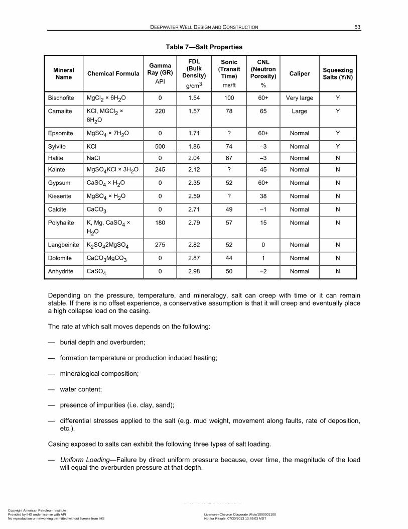
DEEPWATER WELL DESIGN AND CONSTRUCTION 53
Table 7—Salt Properties
Mineral Name
Chemical Formula Gamma
Ray (GR)
API
FDL (Bulk
Density)
g/cm3
Sonic (Transit Time)
ms/ft
CNL (Neutron Porosity)
%
Caliper Squeezing Salts (Y/N)
Bischofite MgCl2 × 6H2O 0 1.54 100 60+ Very large Y
Carnalite KCl, MGCl2 ×
6H2O
220 1.57 78 65 Large Y
Epsomite MgSO4 × 7H2O 0 1.71 ? 60+ Normal Y
Sylvite KCl 500 1.86 74 –3 Normal Y
Halite NaCl 0 2.04 67 –3 Normal N
Kainte MgSO4KCl × 3H2O 245 2.12 ? 45 Normal N
Gypsum CaSO4 × H2O 0 2.35 52 60+ Normal N
Kieserite MgSO4 × H2O 0 2.59 ? 38 Normal N
Calcite CaCO3 0 2.71 49 –1 Normal N
Polyhalite K, Mg, CaSO4 ×
H2O
180 2.79 57 15 Normal N
Langbeinite K2SO42MgSO4 275 2.82 52 0 Normal N
Dolomite CaCO3MgCO3 0 2.87 44 1 Normal N
Anhydrite CaSO4 0 2.98 50 –2 Normal N
Depending on the pressure, temperature, and mineralogy, salt can creep with time or it can remain stable. If there is no offset experience, a conservative assumption is that it will creep and eventually place a high collapse load on the casing.
The rate at which salt moves depends on the following:
— burial depth and overburden;
— formation temperature or production induced heating;
— mineralogical composition;
— water content;
— presence of impurities (i.e. clay, sand);
— differential stresses applied to the salt (e.g. mud weight, movement along faults, rate of deposition, etc.).
Casing exposed to salts can exhibit the following three types of salt loading.
— Uniform Loading—Failure by direct uniform pressure because, over time, the magnitude of the load will equal the overburden pressure at that depth.
Copyright American Petroleum Institute Provided by IHS under license with API Licensee=Chevron Corporate Wide/1000001100
Not for Resale, 07/30/2013 13:49:03 MDTNo reproduction or networking permitted without license from IHS
--``,,`,````,``,`,``,,,`,,``,`-`-`,,`,,`,`,,`---
54 API RECOMMENDED PRACTICE 96
— Nonuniform Loading—Loading over a limited contact area when hole quality is poor (causing significant casing ovality). This is the most severe case because casing collapse resistance reduces rapidly with increased ovality.
— Shear Failure—Occurs at the salt/formation interface caused by lateral movement of the salt relative to the formation. This could happen in a deep, hot salt section overlying a compacting reservoir, but in general, the chances of this occurring are small.
The following are considerations for mitigating salt issues.
a) Maintaining a uniform and in-gauge wellbore geometry.
— Use of nonaqueous or salt-saturated drilling fluids to prevent the salt formation from dissolving.
— The well trajectory through the salt designed to minimize doglegs to reduce salt point loading
b) Maintaining higher mud density through the salt.
— The use of elevated mud densities, approaching the overburden gradient, can reduce the rate of salt movement.
— A casing shoe in salt can exhibit fracture gradients greater than the overburden gradient, thus allowing higher mud gradients to be employed.
c) Under-reaming unstable salt sections to increase annular clearance between the casing and salt.
d) Use of cement systems specifically designed for salt environments.
— Adequate slurry properties to achieve compressive strength as quickly after placement as possible.
— Centralized to provide a continuous protective sheath.
e) Lap strings in salt as soon as possible with an inner string that is fully cemented through the salt section. The pipe cemented inside the larger casing enhances collapse resistance by reducing point loading of the inner string.
f) The use of heavy-wall casing (low D/t ratio casing: diameter of pipe/wall thickness) through salt to improve the casing’s resistance to salt loading.
6.8 Pore Pressure Prediction
The pore pressure and fracture pressure gradients determine the operating mud weight window, which fundamentally defines the casing program. For conventional DW drilling operations, the effective mud weight is maintained above the highest pore pressure in permeable sediment exposed in the open hole plus any additional mud weight required for borehole stability. The pressure exerted by the mud column (which includes surge pressures and/or ECD) should stay below the minimum fracture pressure in the open hole to prevent fracturing of the formation and loss of drilling mud. The difference between the mud hydrostatic pressure and the most recent FIT defines the operating mud weight window, which determines the next casing setting depth.
Some techniques used to estimate the pore pressure in a new well are as follows:
— extrapolation of pore pressure;
Copyright American Petroleum Institute Provided by IHS under license with API Licensee=Chevron Corporate Wide/1000001100
Not for Resale, 07/30/2013 13:49:03 MDTNo reproduction or networking permitted without license from IHS
--``,,`,````,``,`,``,,,`,,``,`-`-`,,`,,`,`,,`---
DEEPWATER WELL DESIGN AND CONSTRUCTION 55
— correlation of over-pressure profiles from offset wells along depth or stratigraphic age boundaries to the prospective well location;
— extrapolation of effective stress profiles (overburden minus pore pressure) to normalize the effect of varying overburden, primarily due to differences in water depth and salt thickness.
Predicting pore pressure from offset wells depends on the similarity in the burial and compaction history, plus the overall hydraulic conductivity between the offset and the drill site location.
Prestack based seismic velocity profiles and other derivative products provide direct information at the proposed drill site that can be used to estimate pore pressure. Velocity data for pore pressure interpretation should be calibrated against the geology and offset well VSP or sonic log data, if available. Uncertainty in accuracy and precision of seismic data increases significantly with depth and below large scale seismic anomalies, such as salt. A robust pore pressure prediction process incorporates multiple pressure methods, and offset interpretations, to develop an appropriate range of uncertainty for basing mud weight program and casing design.
Most pressure interpretation methods infer a pore pressure profile for shale sections and sands equilibrated with the shale. For large and regionally continuous sand bodies, with significant structural relief, pore pressure gradient varies with the fluid pressure gradient within the sand. Thus the pressure gradient in the sand will trend high to the shale gradient up-dip, and trend lower than shale gradient down-dip. This effect will be exaggerated for hydrocarbon columns and should be anticipated where applicable.
While pore pressure does not exist in salt, the stress profile in salt is taken into account. If mud weight is not maintained at a high percentage of the overburden stress, the salt can relax (creep) in the borehole while drilling, causing high torque, stuck pipe, and/or drill string vibration. Additionally, pockets of sediment trapped in inclusions or sutures in salt can fail, or contribute flow into the borehole, unless mud weight is kept at a high percentage of the overburden.
The borehole can become unstable if the principal stresses acting on the borehole are significantly different in opposing directions, the rock is weak, and the mud weight is not high enough to oppose any stress imbalance on the borehole circumference. Wellbore instability is a function of the magnitude and direction of the stresses, the orientation of the well path relative to the stresses, the rock properties, formation dip, and the pore pressure present in the rocks. Wellbore stability analysis uncertainty is a function of uncertainties in pore pressure, in situ stresses, and rock properties.
A simple fracture gradient estimate can be obtained from the overburden gradient, pore pressure gradient, and the effective stress ratio, which describes the behavior of the rock under in situ stress conditions. Sediments with higher effective stress ratios will fracture with mud hydrostatic pressures approaching the overburden stress. Effective stress ratios vary with lithology and are generally higher in shales and lower in sands, silty sands, and carbonates. Salt is a special case, in that fracture gradients in salt can be significantly higher than the overburden, thus enhancing the mud weight window. Stress ratios are determined from offset well casing shoe integrity tests.
Because of the referenced uncertainties in estimation of pore pressure, stress, and fracture gradient prior to drilling, it is important to monitor log measurements and drilling parameters while drilling. The actual data and real-time interpretations should be compared to predrill models to assess the accuracy of the well plan. If changes to the well program and predrill design are required, the changes should be managed by communication, risk assessment and a MOC (where applicable or appropriate).
Copyright American Petroleum Institute Provided by IHS under license with API Licensee=Chevron Corporate Wide/1000001100
Not for Resale, 07/30/2013 13:49:03 MDTNo reproduction or networking permitted without license from IHS
--``,,`,````,``,`,``,,,`,,``,`-`-`,,`,,`,`,,`---
56 API RECOMMENDED PRACTICE 96
6.9 Shallow Hazards Considerations
6.9.1 General
A limited areal extent site survey, that includes shallow seismic, is normally used to evaluate the depth interval down to the surface casing setting depth to check for hydrocarbon accumulations at the planned location and to map the areal extent of any potential shallow water flow (SWF) zones. When selecting the well location, the planning team assesses the shallow hazards risk. This includes SWF, in situ gas hydrates, shallow gas, or other potential hazards.
6.9.2 Shallow Water or Gas Flow
In many DW environments, shallow sediments were rapidly deposited and did not have time to bleed off excess pressure during compaction and reach a normal hydrostatic gradient. This results in shallow sediments becoming pressured to levels above a seawater gradient. When this occurs in shallow unconsolidated sediments, water, gas, and/or sediment flows can result if the formation becomes underbalanced.
If the flow is left unaddressed it can cause the following:
a) create instability in the formations surrounding the structural or conductor pipe;
b) prevent casing strings from reaching bottom;
c) prevent successfully cementing a casing string;
d) result in sediment buildup at the mudline (which can rise to a height greater than the wellhead and make it difficult to see the well or land the BOPs in extreme cases);
e) create subsequent buckling and/or casing wear;
f) destabilize the local shallow sediments leading to the loss of the well or multiple wells in a template, potentially allowing the release of fluids or hydrocarbons to the mudline.
When practical, avoid drilling in sites with potential shallow hazard zones. If a shallow hazard zone cannot be avoided, the recommended DW industry practice is to drill the interval overbalanced while pumping mud and taking returns to the mudline to prevent the sand from flowing fluids or formation material. Pressure while drilling tools are often used to aid in kick detection or packoff detection. In the case where the bottom survey indicates the potential presence of shallow hazards, the use of a pilot hole should be considered.
In areas where shallow hazards exist, running an additional conductor casing string above the shallow hazard zone should be considered when one or more of the following is anticipated:
— shallow gas;
— abnormal pressure;
— weak structural casing shoes.
This can reduce potential problems caused by subsidence, broaching, and severe washout. These can create sediment buildup at the mudline and interfere with drilling operations.
Copyright American Petroleum Institute Provided by IHS under license with API Licensee=Chevron Corporate Wide/1000001100
Not for Resale, 07/30/2013 13:49:03 MDTNo reproduction or networking permitted without license from IHS
--``,,`,````,``,`,``,,,`,,``,`-`-`,,`,,`,`,,`---
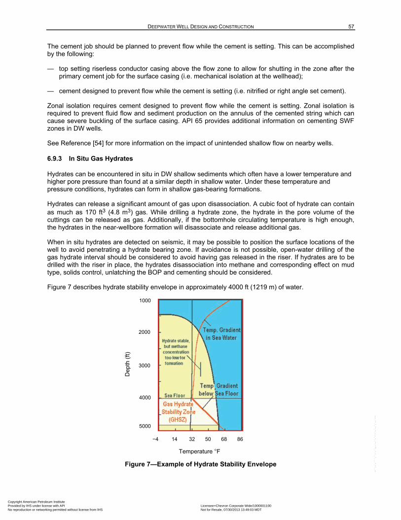
DEEPWATER WELL DESIGN AND CONSTRUCTION 57
The cement job should be planned to prevent flow while the cement is setting. This can be accomplished by the following:
— top setting riserless conductor casing above the flow zone to allow for shutting in the zone after the primary cement job for the surface casing (i.e. mechanical isolation at the wellhead);
— cement designed to prevent flow while the cement is setting (i.e. nitrified or right angle set cement).
Zonal isolation requires cement designed to prevent flow while the cement is setting. Zonal isolation is required to prevent fluid flow and sediment production on the annulus of the cemented string which can cause severe buckling of the surface casing. API 65 provides additional information on cementing SWF zones in DW wells.
See Reference [54] for more information on the impact of unintended shallow flow on nearby wells.
6.9.3 In Situ Gas Hydrates
Hydrates can be encountered in situ in DW shallow sediments which often have a lower temperature and higher pore pressure than found at a similar depth in shallow water. Under these temperature and pressure conditions, hydrates can form in shallow gas-bearing formations.
Hydrates can release a significant amount of gas upon disassociation. A cubic foot of hydrate can contain as much as 170 ft3 (4.8 m3) gas. While drilling a hydrate zone, the hydrate in the pore volume of the cuttings can be released as gas. Additionally, if the bottomhole circulating temperature is high enough, the hydrates in the near-wellbore formation will disassociate and release additional gas.
When in situ hydrates are detected on seismic, it may be possible to position the surface locations of the well to avoid penetrating a hydrate bearing zone. If avoidance is not possible, open-water drilling of the gas hydrate interval should be considered to avoid having gas released in the riser. If hydrates are to be drilled with the riser in place, the hydrates disassociation into methane and corresponding effect on mud type, solids control, unlatching the BOP and cementing should be considered.
Figure 7 describes hydrate stability envelope in approximately 4000 ft (1219 m) of water.
Figure 7—Example of Hydrate Stability Envelope
1000
2000
3000
4000
5000
−4 14 32 50 68 86
Temperature F
Dep
th (
ft)
Copyright American Petroleum Institute Provided by IHS under license with API Licensee=Chevron Corporate Wide/1000001100
Not for Resale, 07/30/2013 13:49:03 MDTNo reproduction or networking permitted without license from IHS
--``,,`,````,``,`,``,,,`,,``,`-`-`,,`,,`,`,,`---
58 API RECOMMENDED PRACTICE 96
6.10 Gas Hydrate Formation
When free gas is present in the wellbore (such as during well control events), gas can be trapped beneath closed BOPs or closed C/K valves. Near the mudline, the combination of cool temperatures and pressurized gas can cause the formation of hydrates, which can plug the C/K lines, as well as the wellbore, and prevent circulation. This problem normally does not occur with NAF because the water is emulsified in the oil phase and the water phase has a high salinity. See Reference [57] for more information on the impact of hydrate formation on BOP operations.
Documented incidences of hydrates formation during well control events have occurred in water-based muds (WBM). When using WBM, the use of a high salinity and/or glycol mud should be considered to inhibit the formation of hydrates. If WBM is used, or the upper portion of the well is displaced to seawater, spotting a high salinity glycol pill in the wellbore and across the BOPs should be considered to inhibit the formation of hydrates during extended periods without circulation.
Hydrate formation should also be considered during completion operations. Completion operations typically involve exposed reservoir formations and are often executed for long periods of time under static conditions. Static conditions cause wellbore cooling near the mudline and thus create a condition conducive to hydrate formation. Completion fluids should be selected that are hydrate-inhibitive.
Hydrates can form external to the well bore and BOP when gas migrates from shallow formations around the well bore and collects in protected pocketed areas such as hydraulic wellhead connectors and BOP frame components. Hydrate formation around and within hydraulic connectors can prevent the release of the LMRP, such as during an EDS event. It can also prevent the release of the BOP stack from the HPWHH. Risk mitigations methods may include
— the use of hydrate exclusion seals on the hydraulic connectors,
— the installation of ROV accessible hydrate inhibition injection ports on the hydraulic connectors, or
— the installation of gas diversion systems to deflect the methane away from the BOP and LMRP.
6.11 Liner Hangers
6.11.1 General
Liner hangers provide the ability to support the weight of a liner in the casing in which they are set. When equipped with an external packer element, they also provide a barrier to annular flow. The packer element, when set, isolates the annulus above and below the packer. Load cases for liners are a subset of load cases for the casing.
Production liner hanger systems can be categorized as follows.
— Production Liners Hung off Inside Production Casings—Production liner hanger performance and the reliability of the annular pressure barrier can be enhanced if the liner is well cemented within the production casing. If there is no cement in the lap, then the system integrity is determined by the elastomer seal integrity, the capacity of the slips and hold-down mechanism, and the capacity of the various machined components/cylinders. A tight clearance well architecture design can limit the capability of the liner hanger and necessitate setting it higher in a larger string, if possible. These issues should be carefully considered by the well designer.
— Production Liners Hung off Inside Drilling Casings (Liner to be Tied Back for Production)—The production liner/tieback configuration introduces additional annular barriers above that of a production liner alone. These barriers are the tieback cement and the tieback wellhead seal assembly.
Copyright American Petroleum Institute Provided by IHS under license with API Licensee=Chevron Corporate Wide/1000001100
Not for Resale, 07/30/2013 13:49:03 MDTNo reproduction or networking permitted without license from IHS
--``,,`,````,``,`,``,,,`,,``,`-`-`,,`,,`,`,,`---
DEEPWATER WELL DESIGN AND CONSTRUCTION 59
Cementing the tieback prevents the tieback seals from moving due to changes in pressure or thermal loads thus improving seal reliability.
Production liner hangers should have long-term reliability to contain and control the produced fluids over the life of the well. The effects of full shut-in load on a column of packer fluid as well as collapse loads due to APB for the production case (tubing in place) should be considered. Production liner hangers can also require different metallurgy appropriate for the produced fluid. Examples of liner hanger considerations include the following.
a) Material selection for liner hanger equipment is similar to that used for the tubulars above and below the liner hanger system.
b) H2S service applications, reference NACE MR0175.
c) corrosion resistant alloy (CRA) materials may be considered if the liner hanger system is in the wetted flow path for water injection or CO2 service.
d) Design liner hangers for expected pressures and combined loads.
e) The burst and collapse rating of the liner hanger system relative to the ratings of the liner and outer casing compared to design requirements.
f) In close tolerance liner hanger configurations (e.g. 13 5/8-in. × 11 7/8-in. and 11 7/8-in. × 9 3/8-in.), it is difficult for a hanger design to provide the burst and collapse ratings of high strength tubulars being used. To increase the system reliability in these applications, positioning the PBR below the hanger body should be considered to isolate the hanger body when tying back the casing. If the current liner is run in a well where the last string was also a liner, setting the hanger of the current liner in the next larger string should be considered. Setting the hanger in the next larger string can also allow sufficient clearance to design the PBR with higher burst and collapse capability than in close tolerance applications.
g) Collapse loads (including APB) on tieback sleeves and PBRs when tied back.
The packer sealing elements on liner hangers (and LTPs) are considered reliable if used within their design limits, service conditions, and installed successfully. If casing wear is expected in the string in which the liner will be set, running a caliper or casing evaluation log should be considered to help select the hanger setting depth. Avoid setting the hanger in connections, worn casing, high doglegs, previous shoe tracks (internally cemented pipe with a possible cement sheath) or in uncemented pipe.
Some liner hangers (hydraulically set) have internal ports and pistons with sealing areas that are used to set the hanger. These ports and seals can experience long-term exposure to wellbore fluids if they aren’t isolated. This reduces the reliability of the hanger packer as a barrier because it provides another pressure containment failure path. The reliability of a hanger packer as a barrier can be increased by eliminating the internal ports and sealing areas as a possible leak path. This is accomplished by either using a liner/tieback well architecture and positioning the tieback PBR below the liner hanger or by using a liner hanger system without internal ports (mechanical set or expandable).
The pressure and tensile load ratings of hanger systems may be limited by the slip design. In many cases, the pressure that can be applied to the top element of a LTP is limited by the slip loading capacity. Slip capacity ratings are related to the weight and grade of the outer casing along with the presence of external support in the adjacent casing annulus. Cemented casing provides backup to slip loading and increases the total load capacity.
Copyright American Petroleum Institute Provided by IHS under license with API Licensee=Chevron Corporate Wide/1000001100
Not for Resale, 07/30/2013 13:49:03 MDTNo reproduction or networking permitted without license from IHS
--``,,`,````,``,`,``,,,`,,``,`-`-`,,`,,`,`,,`---
60 API RECOMMENDED PRACTICE 96
6.11.2 Expandable Liner Hangers
Expandable hangers are built from a solid hanger body and may have bonded elastomeric elements on the outside. These types of hangers are expanded after they are run in place. The expanded hanger body and bonded elastomeric elements provide a bidirectional annular seal with multiple redundant seal elements. These seal elements also support the liner weight and tensile/compressive loads on the liner hanger as the result of various life cycle operating conditions.
6.11.3 Seals and Seal Stem
If the seals used in the tieback receptacle are exposed to production fluids, they should have long term reliability to contain and control the produced fluids over the life cycle of the well. Seal materials are selected based on well conditions (e.g. temperature and pressure) and compatibility with well fluids. Seal movement from changing thermal or pressure loads can reduce seal reliability. Cementing the tieback should be considered to prevent these movements. A tieback creates a trapped annulus that may require mitigation of APB.
The seal stem and tieback PBR can have a reduced burst and collapse capacity. Positioning the seal stem in the PBR, so that it fully engages or bottoms out in the PBR can increase the collapse rating of the PBR/tieback stem system by reducing the exposed length of unsupported PBR. However, fully engaging a tieback stem in a PBR can add complexity such as the introduction of a tieback liner.
6.12 Expandable Tubular Goods
Expandable tubular goods (ETG) may be used for well construction, including DW well designs, when conventional well designs are not adequate to maintain the objective hole size at TD. ETG are most commonly used as drilling liners, although other applications include cased hole cladding to protect damaged casing and open-hole cladding to isolate a troublesome interval. An ETG is run as a tight tolerance liner below a conventional protective casing or liner. When on bottom, the ETG liner is expanded from the interval TD into the last exposed casing or liner to retain sufficient clearance for drilling the next hole interval.
Postexpansion ETG material is a thin-wall steel tubular that has reduced burst, collapse, and tensile capacities compared to conventional casing. As a result, the ETG drilling liner is treated as a “casing shoe extension” to increase effective shoe strength or case off a troublesome interval. Therefore, the load cases evaluated when designing an ETG are reduced to only those functional loads required to run and install the ETG, test ETG and liner shoe integrity, and drill to the next casing/liner point.
While nested ETG have been installed, a single ETG liner is typically installed and then is cased off by a conventional liner or casing as soon as practical to protect the well from the reduced ETG load ratings. In all cases, conventionally designed casing and/or liners above the ETG will provide the final well control barrier as the ETG is considered a shoe extension.
When designing the ETG drilling liner, the following loads should be considered:
— running;
— cementing;
— expanding;
— pressure testing;
— shoe testing;
— drilling loads.
Copyright American Petroleum Institute Provided by IHS under license with API Licensee=Chevron Corporate Wide/1000001100
Not for Resale, 07/30/2013 13:49:03 MDTNo reproduction or networking permitted without license from IHS
--``,,`,````,``,`,``,,,`,,``,`-`-`,,`,,`,`,,`---
DEEPWATER WELL DESIGN AND CONSTRUCTION 61
The collapse rating of ETG liners is low when compared to conventional casing or liners, making them more sensitive to mud weight and pore pressure changes (e.g. pore pressure regression or depletion). Therefore, the collapse load case evaluated is the maximum evacuation that can be achieved while maintaining the target collapse design factor. These design limits shall be documented. The expansion of ETG or expandable liner hangers downhole can increase susceptibility to cracking in corrosive environments.
6.13 Alloys in a Cracking or Corrosive Environment
All tubing and production casing designs should consider the potential for corrosion and cracking resulting from exposure to fluids (i.e. produced, completion). The risk of corrosion and cracking is defined by a combination of factors including acid gas concentration and partial pressures, chloride concentration, in situ pH, metallurgy, and temperature. Sulfide stress cracking is enhanced at lower temperatures due to hydrogen damage. Stress corrosion cracking occurs at higher temperatures with various fluid chemistries (H2S, pH, chloride).
NACE MR0175 /ISO-15156 provides guidelines for selection of CRAs in various wellbore conditions (i.e. stress level, pH and partial pressure). Alternatively, fitness for service testing of a material can be used to characterize the corrosion resistance, sulfide stress cracking resistance, and stress corrosion cracking resistance for the relevant flowing and shut-in conditions of the well.
Tubular capacity in a sour environment is addressed in API 5C3, and the SSC design basis is addressed specifically for carbon steels. However, conservative Kmat values and residual stress should be
considered in the final evaluation. For carbon steel casing in a H2S environment, the ductile rupture formula cited in ISO 10400 can only be used if the pipe has appropriate fracture toughness in the sour environment as described in API 5C3, Annex D. NACE TM0177, Method D describes the applicable fracture toughness test.
API 5CT provides guidelines for QA/QC and material specifications for carbon steels. API 5CRA provides guidelines on QA/QC and material specifications for CRA materials.
6.14 Downhole Threaded Connections
The following should be considered for the selection of downhole threaded connections.
a) The use of connections designed with a metal-to-metal seal feature to assemble casing joints that will be exposed when drilling hydrocarbon zones, especially for gas zones below surface casing. Due to clearance considerations, most DW casing connections are flush or semiflush.
b) Intermediate casing connection wear while drilling—flush or semiflush connections can have less wear tolerance than threaded and coupled connections. Additional wear mitigations (e.g. thread design/metal-to-metal seal placement, modeling, thread compound type) should be considered when using these types of connections.
c) Testing the intermediate casing connections that can be exposed to hydrocarbons (e.g. during a well control situation) in accordance with API 5C5.
d) Production casing—a connection successfully qualified using the criteria for either of the two most stringent connection application levels of API 5C5 should be considered. This is particularly important where external pressure sealing is required. Alternatively, sufficient field experience with expected production casing loads and conditions can be used as a technical basis for determining that the connection is fit-for-use.
e) Production tubing—a connection successfully qualified using the criteria for either of the two most stringent connection application levels of API 5C5 should be considered. This is particularly important
Copyright American Petroleum Institute Provided by IHS under license with API Licensee=Chevron Corporate Wide/1000001100
Not for Resale, 07/30/2013 13:49:03 MDTNo reproduction or networking permitted without license from IHS
--``,,`,````,``,`,``,,,`,,``,`-`-`,,`,,`,`,,`---
62 API RECOMMENDED PRACTICE 96
where external pressure sealing is required. Alternatively, sufficient field experience with expected production tubing loads and conditions may be used as a technical basis for determining that the connection is fit-for-use.
f) The API 5C5 laboratory testing provides discriminating qualification of the connection design within its manufacturing and makeup tolerances. Equally important are manufacturing process control, QA process, and a field deployment (installation) procedure consistent with the connection design that was qualified. These processes are essential in assuring that the connection, as manufactured and installed in the well, is consistent with the product qualified in laboratory testing. The following elements should also be considered:
— quality system;
— QC and inspection, including first and last article manufactured;
— thread compound (type and application);
— field deployment procedures (including monitoring shoulder torque and final make-up torque using torque-turn monitoring and tong control, if applicable);
— successful field experience.
NOTE Consult the connection supplier when considering extrapolating tests across different sizes, weights, and/or material grades.
6.15 Casing Landing Strings
6.15.1 General
DW well designs routinely incorporate casings and liners that are run on drill pipe or dedicated landing strings. The design and inspection of the landing string is critical, as the well depths can create extreme casing and liner loads. Most DW landing strings are full-length inspected to 90 % to 95 % minimum wall thickness for every joint, compared with the 80 % minimum wall thickness criterion for regular drill pipe. Failure to properly design and inspect landing strings, running tools, and hoisting equipment can result in dropped casings. Landing strings are not normally used for drilling and therefore may not have fatigue resistant features, thus increasing capacity.
6.15.2 Static and Dynamic Axial Loads
A dedicated landing string or drill pipe is used to run all DW casing strings and is designed with adequate tensile capacity, including:
a) a design factor to support the expected static weight casing and the landing string/drill pipe,
b) a margin of over pull plus those dynamic loads associated with acceleration loads while running the casing,
c) the acceleration load associated with DW floating rig’s response to metocean conditions.
The static casing running load and designed margin of over-pull calculations, addressed in Section 7.4 of API 7G, can be calculated manually or by using engineering design software. The dynamic loads associated with the running of casing are calculated by using engineering design software while making assumptions on pipe running speeds and deceleration as the landing string is set in the slips.
Copyright American Petroleum Institute Provided by IHS under license with API Licensee=Chevron Corporate Wide/1000001100
Not for Resale, 07/30/2013 13:49:03 MDTNo reproduction or networking permitted without license from IHS
--``,,`,````,``,`,``,,,`,,``,`-`-`,,`,,`,`,,`---
DEEPWATER WELL DESIGN AND CONSTRUCTION 63
Floating vessel motion also impacts dynamic loads on the landing string. These loads are dependent on the vessel response amplitude operators and the sea state. Analyze the casing and landing string for the allowable sea state to avoid dynamic failure of the landing string. Additionally, open-water versus through-marine-drilling-riser deployment should be considered in the design.
6.15.3 Slip Crushing
Slip crushing is the deformation of the landing string caused by biaxial loading of the tube in the slip contact area. Slip crushing occurs when the combined axial loading on the tube and the transverse force caused by the slips begin to yield the pipe ID at the slips. Slip crushing is a complex failure mechanism and the equations describing slip crushing have uncertainty. Therefore, it is recommended that a design factor be applied to provide that the expected landing string load does not exceed the yield strength of the landing string.
Slip crushing can be especially severe when running casing in DW wells because all casing strings are run and landed with drill pipe. Slip crushing is dependent on many factors including the friction in the slips and bowl, wear between the slips and bowl, geometry, and the design of the slips and bowl. Slip crushing of landing strings may be mitigated through the use of high capacity slips and bowl systems.
Alternative solutions include the use of dual-shouldered landing strings (which use a slip-less spider), dual elevators or using slip crush-proof tube drill pipe. For more information on slip crushing refer to API 7G-2.
6.15.4 Inspection of Hoisting Equipment and Components
Running heavy casing strings can put high loads, relative to rated capacities, on the entire hoisting system, which includes the landing string, bowl and slips, elevators, bails, block, derrick, substructure, and top drive system assemblies. Periodically inspect the dedicated landing string, as described in Annex E of API 7G-2, to demonstrate that the equipment is fit-for-purpose in the expected service conditions. The other hoisting equipment should be inspected in accordance with API 8B.
6.16 Tension Leg Platforms/Spar Considerations
6.16.1 General
Wells may be predrilled with a floating rig and then completed and operated from a DW floating platform. While this document does not address spar or TLP operations, the following are issues that should be considered when predrilling wells that may later be completed to a floating platform. Well design is often platform specific and requires a separate load analysis.
6.16.2 Collapse Loads
Some completion designs for TLPs and spars use only a production riser and tubing above the mudline. To minimize heat transfer from the producing fluid into the seawater column, the production riser by the tubing annulus is, in some cases, filled with low-pressure nitrogen. This creates a collapse load nearly equivalent to full evacuation at the mudline. This load condition should be considered during the design of the production casing, any exposed liner tops, and tubing. Refer to API 2RD and API 17G for more information on riser types and design.
6.16.3 Transfer of Axial Loads
Wells completed with dry trees to a spar or TLP, in some designs, try to minimize the weight of tubulars supported by the floating facility. In these cases, the below mudline weight of production casing and tubing is carried by the next outer casing string. The production casing carries the load of the tubing, and the protective casing carries the load of the production casing. The mechanism used to transfer the axial load also imparts a radial load to the outer casing string. In the design of the protective and production
Copyright American Petroleum Institute Provided by IHS under license with API Licensee=Chevron Corporate Wide/1000001100
Not for Resale, 07/30/2013 13:49:03 MDTNo reproduction or networking permitted without license from IHS
--``,,`,````,``,`,``,,,`,,``,`-`-`,,`,,`,`,,`---
64 API RECOMMENDED PRACTICE 96
casing strings the additional axial and radial loads that can be imparted should be considered. This may require thicker wall casing or other features to resist radial loads or to carry additional axial loads and higher potential collapse loads.
6.16.4 Fatigue/Bending Loads
Wells completed with dry trees to a spar or TLP usually use a tapered stress joint instead of a flex joint or ball joint at the bottom of the drilling or production riser. The bending moment imparted by the tapered stress joint is different than that normally imparted by a flex joint. TLP/spar designs normally leave the drilling or production riser attached for the lifecycle of the well. Metocean events such as hurricanes and loop currents can impose higher static bending loads, as well as impart more cyclic bending loads that can cause fatigue damage. Additional future loads and load history should be considered when designing the subsea wellhead and tubulars connected to the subsea wellhead. For example, higher bending loads could occur during operations by drive offs with no disconnect and by use of a “capping stack” (another BOP stack that may be placed on top of a nonfunctioning primary BOP stack).
NOTE Some HPWHH utilize preloading to the LPWH to improve fatigue resistance and torque resistance.
6.17 Annular Pressure Build-up Considerations
6.17.1 Background
Subsea wellheads used to drill in DW do not have access to most outer annuli in the well. Typically, only the tubing by the production casing annulus, known as the “A” annulus, can be monitored and pressure bled down. The pressures occurring in the other annuli cannot be monitored. The well’s capacity to withstand the pressure changes during well construction and production operations should be considered when designing the well. Calculations of potential pressure changes can be considered to determine the severity of the issue and whether mitigation is necessary. Due to the potential multiple annuli exposed, computerized multistring analysis is often used to determine the severity of the problem. The casing design should reflect the APB mitigation strategy.
6.17.2 Trapped Annulus Pressure
If the annulus is sealed from pressure in the open hole below the deepest shoe, the increased temperature of trapped fluid will cause the fluid or gas to expand. The amount of pressure increase depends on the types of fluid in the annulus and the change in temperature from initial conditions. This situation is often referred to as trapped annulus pressure or annular pressure buildup (APB).
In addition to trapped casing annuli (shown as the “B” and “C” annuli in Figure 8), there are other areas that may contain trapped fluid volumes. Consider fluid trapped between tubing hanger plugs in a horizontal tree or other similar areas in subsea trees, tubing hangers, and wellhead connectors that may see a large differential between initial installed condition and flowing production temperatures. This temperature increase can cause a significant pressure increase. Considerations should be taken to managing or mitigating this pressure increase.
DW wells can be susceptible to large temperature increases since the initial installed temperature can be as low as the mudline temperature, 38 °F to 40 °F (3.3 °C to 4.4 °C). Many DW well formation temperatures exceed 200 °F (93 °C) and can produce at very high flow rates which can bring bottomhole static temperature (BHST) to near the mudline.
Over time, the fluid gradient and fluid properties in an annulus can change from initial conditions at time of placement for the following reasons.
a) Gas migration due to imperfect cement job. This can cause partial or full replacement of annular fluid in the annulus with gas. The maximum resulting pressure below the seal (liner hanger or wellhead)
Copyright American Petroleum Institute Provided by IHS under license with API Licensee=Chevron Corporate Wide/1000001100
Not for Resale, 07/30/2013 13:49:03 MDTNo reproduction or networking permitted without license from IHS
--``,,`,````,``,`,``,,,`,,``,`-`-`,,`,,`,`,,`---
DEEPWATER WELL DESIGN AND CONSTRUCTION 65
would then be limited by either the reservoir pressure less a gas gradient or the fracture gradient at the deepest shoe less a gas gradient
b) Over time, the solids suspended in the annulus fluid can settle. This could cause annular fluid degradation resulting in a low fluid density in the top of the interval (as low as the base fluid density) and a higher fluid weight in the bottom section.
NOTE The settled weighting material can create a barrier in the annulus, restricting APB pressure relief to an uncemented open-hole interval below the previous shoe.
Figure 8 shows a subsea tree with a tubing head and “A” annulus access.
NOTE The well architecture shown in Figure 8 is an example of the “normal clearance well” shown in Figure 3.
6.17.3 Design Considerations
APB can cause both a burst load on the outer casing and a collapse load on the inner casing string. The increased annulus pressure can also cause a piston-effect axial load to be exerted on the hanger. The backup fluid gradient for the burst or collapse case could be as high the original mud or as low as the solids-free fluid.
6.17.4 APB Mitigations
Potential APB mitigation may include the following.
a) Avoid a sealed annulus by
— leaving the TOC a sufficient depth below the previous casing shoe to prevent the annulus from being trapped from the open hole by either cement or settled mud solids (refer to regulatory requirements to ensure conformance) and
— using a solids-free fluid, such as a weighted brine, in the cased hole annulus to avoid solids settling and potential plugging.
b) Installing a compressible gas or fluid in the annulus by
— using a compressible gas, such as nitrogen, so that as the fluid expands and the nitrogen volume contracts, the increase in nitrogen pressure is less than the burst or collapse rating of the casing, and
— using compressible liquids; compressibility of these liquids are generally much lower than nitrogen.
c) Installing crushable material on the outside of the casing, such as syntactic foam, is another potential solution. The material crushes as annulus fluid expands, providing additional volume for fluid expansion which reduces the pressure buildup.
NOTE Crushable material does not fully reexpand after it is crushed. Therefore, the number of thermal cycles that it can mitigate is limited.
d) Using rupture disks in the casing to protect either the outer or inner casing string. Rupture disks can be designed to fail either with an internal or external pressure. They are manufactured to fail at a specific pressure for a given temperature with a very tight tolerance on their design capacity. A strict QC program is essential for the manufacturing and installation of the rupture disks to ensure that the casing, deployed sub, and installed disk or disks perform as intended.
Copyright American Petroleum Institute Provided by IHS under license with API Licensee=Chevron Corporate Wide/1000001100
Not for Resale, 07/30/2013 13:49:03 MDTNo reproduction or networking permitted without license from IHS
--``,,`,````,``,`,``,,,`,,``,`-`-`,,`,,`,`,,`---
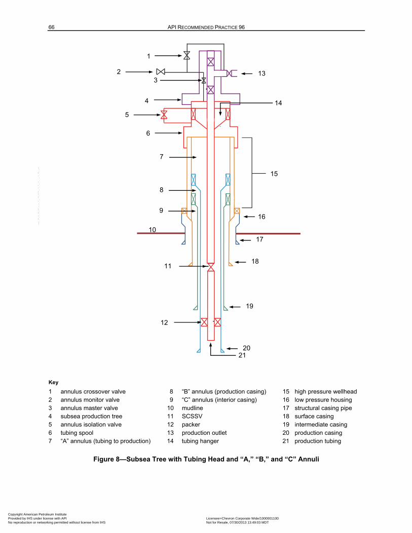
66 API RECOMMENDED PRACTICE 96
Key
1 annulus crossover valve 8 “B” annulus (production casing) 15 high pressure wellhead 2 annulus monitor valve 9 “C” annulus (interior casing) 16 low pressure housing 3 annulus master valve 10 mudline 17 structural casing pipe 4 subsea production tree 11 SCSSV 18 surface casing 5 annulus isolation valve 12 packer 19 intermediate casing 6 tubing spool 13 production outlet 20 production casing 7 “A” annulus (tubing to production) 14 tubing hanger 21 production tubing
Figure 8—Subsea Tree with Tubing Head and “A,” “B,” and “C” Annuli
•
.
• •
85 23
9
7
8
15
11
16
17
18
21
14
19
20
13
10
4
6
78
1 1
11
1
2 3
5
12
21
Copyright American Petroleum Institute Provided by IHS under license with API Licensee=Chevron Corporate Wide/1000001100
Not for Resale, 07/30/2013 13:49:03 MDTNo reproduction or networking permitted without license from IHS
--``,,`,````,``,`,``,,,`,,``,`-`-`,,`,,`,`,,`---
DEEPWATER WELL DESIGN AND CONSTRUCTION 67
Ensure that rupture disk activation will not result in hydrocarbon discharge or broaching to mudline. For example, this allows the use of rupture disks exposed to hydrocarbons when
— rated higher than the burst survival load,
— the casing outside the rupture disk can contain the survival based pressures without broaching to sea floor or bursting, and
— when used to protect deep liners from collapse, preserving well bore access.
Using insulation methods to limit the transfer of heat from the production flow stream to the casing annuli. Examples include vacuum insulated tubing (VIT) which limits heat transfer to the annulus and insulating packer fluids which limit heat transfer caused by convection in the annulus. See additional information on VIT in 7.4.
6.18 Annular Abandonment Considerations
The permanent abandonment of DW wells may or may not require the removal of the wellhead and casing to a regulated depth below the mudline. This is typically based on water depth and governed by local regulations and the potential for use of the seafloor for other activities (e.g. fishing). For wells where the water depth and local regulations require the removal of the wellhead, the final isolation of the casing annuli during abandonment should be considered. For example, if the wellbore has been designed to mitigate APB, the annuli may not contain barriers and may provide a path for communication with uncemented formations. When the wellhead is not removed, refer to local regulations for annular isolation.
In wells that need to be permanently abandoned, where the “B” annulus (behind the production casing) has uncemented hydrocarbon bearing formations that can communicate up to the mudline through this annulus, these formations shall be isolated from the mudline by either perforating the production casing and squeezing cement, or cutting and pulling a section of the production casing and subsequently squeezing the annulus.
Uncemented annuli between strings outside the “B” annulus can provide a conduit to the mudline to flow originating below. Similar to the “B” annulus, these annuli can be isolated by either perforating and squeezing cement, or by cutting and pulling a section of casing followed by squeezing cement. Should the option to perforate and squeeze an outer annulus be selected, then special consideration should be given to the design of the guns so that they will perforate through multiple casing strings.
7 Special Considerations for Completions
7.1 Completion Fluids
Solids-free completion fluids are often used in the wellbore to minimize damage to the formation during cased hole completions. In open-hole completions, a variety of solids-laden and solids-free fluids are used in the cased hole portion of the wellbore before running any screens that will be placed in the open hole. Check the compatibility of the completion fluid with the following:
— various materials of the upper and lower completion equipment;
— formations exposed in the open hole or from perforations;
— formation fluids;
— stimulation fluids;
Copyright American Petroleum Institute Provided by IHS under license with API Licensee=Chevron Corporate Wide/1000001100
Not for Resale, 07/30/2013 13:49:03 MDTNo reproduction or networking permitted without license from IHS
--``,,`,````,``,`,``,,,`,,``,`-`-`,,`,,`,`,,`---
68 API RECOMMENDED PRACTICE 96
— BOP elastomers.
The density of a brine will vary depending on its temperature and can affect the resulting bottomhole pressure. Depending on the operation being performed, the brine can be heated through exposure to geothermal temperatures or cooled due to exposure to the cooling effect of the seawater column.
Completion brines exposed to low temperatures and/or high pressures can crystallize. This situation can occur at the mudline when testing the BOPs, tubing hanger, subsea production tree, or during a well control event. The designer specifies environmental criteria and required test pressure when choosing a brine. This ensures that the pressurized crystallization temperature for the chosen brine is equal to, or cooler than, the temperature of seawater at the mudline when exposed to pressures equivalent to the hydrostatic pressure of the brine at the mudline plus the maximum surface test pressure or anticipated shut-in pressure at the mudline. There have been cases where the brine has crystallized when pressure testing DW BOPs.
7.2 Materials
7.2.1 General
The differences in the material properties of the completion components during tubing stress analysis should be considered. Different materials can have different properties such as Young’s modulus, Poisson’s ratio, temperature deration of yield strength and thermal coefficient, and anisotropic (directionally dependent) variables. Corrosion-resistant alloy (CRA) materials can have different properties for the same alloy based upon the process used in manufacturing.
The interaction between potential fluids and selected materials throughout the well’s life cycle should be considered.
7.2.2 Erosion/Corrosion
Corrosion of tubing ID can occur depending on the tubing material type, compositional properties of the produced fluid, and the chemicals used during its completion and production life. The flow of fluid inside the tubing can erode component surfaces. In some cases, it can continue to expose new surfaces to corrosion, which leads to pitting or even loss of wall thickness. This can also occur in the portion of the production casing exposed to flow during production.
The designer should consider these issues over the full life of the well. Some methods for addressing these issues are to use more CRA or include additional wall thickness to account for potential wall loss depending on metallurgy selection.
7.2.3 External Corrosion
The external tubing surface is exposed to packer fluid and/or lifting gas in the “A” annulus and could be exposed to produce fluids during the operating life of the well. Select packer fluid and/or lifting gas properties based on the tubing material corrosion rate.
7.2.4 Corrosion Resistant Alloy Materials
The proper use of CRA materials is critical in corrosive environments and is addressed in API 5CRA. However many CRA materials are not addressed by current API specifications. The following should be considered:
a) nonisotropic MYS properties (axial, hoop, radial);
b) deration of MYS with elevated temperature;
Copyright American Petroleum Institute Provided by IHS under license with API Licensee=Chevron Corporate Wide/1000001100
Not for Resale, 07/30/2013 13:49:03 MDTNo reproduction or networking permitted without license from IHS
--``,,`,````,``,`,``,,,`,,``,`-`-`,,`,,`,`,,`---
DEEPWATER WELL DESIGN AND CONSTRUCTION 69
c) nonuniform MYS in thick sections (for connection design);
d) tubular wall thickness variability;
e) grade range;
f) material handling (tong or slip marks can adversely affect performance of CRAs);
g) material compatibility of components in the string.
7.2.5 Temperature Cycling
Address temperature cycling effects between cold and hot temperatures in the design of the tubing and elastomers. Due to the cool temperatures seen near the mudline in DW, temperature extremes can be more severe than those in shallow water or onshore wells.
The temperature can vary from cold injection seawater temperatures at the mudline to reservoir BHST during production. These changes in temperature can affect tubing stresses and movements in varying ways such as compression, tension and triaxial loads. Component ratings should be considered when designing for the anticipated temperature ranges.
7.2.6 Liquid/Gas Fluid Effect on Elastomers
The following liquid/gas fluid effects on elastomers should be considered in the design:
— the effect of exposure to different fluids during the well construction process and producing life (acid, completion brine, produced fluids, and frac fluids, etc.) on elastomer properties and reliability;
— the migration of gas into the elastomer.
NOTE If the pressure of the wellbore is suddenly decreased, the gas can rapidly expand and cause damage to the elastomer. This “explosive decompression” issue can be more critical for barriers in the subsea production tree than elastomers located deeper in the well.
7.3 Tubing/Work String Connections
Tubing connections are subjected to varying loads over the life of the well. The following load cases should be considered:
— tension/compression, burst/collapse, thermal and bending loads;
— cyclic loads
The following shall be considered when selecting/designing tubing/work string connections.
a) Connection sealing type:
— metal-to-metal radial seal(s);
— thread seal based on combination of tight fitting thread and appropriate thread compound;
— thread seal plus elastomer seal rings;
— alternatives.
Copyright American Petroleum Institute Provided by IHS under license with API Licensee=Chevron Corporate Wide/1000001100
Not for Resale, 07/30/2013 13:49:03 MDTNo reproduction or networking permitted without license from IHS
--``,,`,````,``,`,``,,,`,,``,`-`-`,,`,,`,`,,`---
70 API RECOMMENDED PRACTICE 96
b) Production tubing—a connection successfully qualified using the criteria for either of the two most stringent connection application levels of API 5C5 should be considered. This is particularly important where external pressure sealing is required. Alternatively, sufficient field experience with expected production tubing loads and conditions may be used as a technical basis for determining that the connection is fit-for-use.
7.4 Flow Assurance
7.4.1 General
Flow assurance is the control or mitigation of the deposition/formation of hydrates, wax, asphaltenes, and scale in the production flow path. Many factors affect flow assurance such as fluid composition, pressure, flow rate and temperature. Fluids in the wellbore can experience significant temperature changes, and plugs can form as a result. Flow assurance is provided by chemical and/or thermal management. Design of the total system should consider the wellhead and tree, which have the highest heat loss.
Some methods of prevention used in industry are as follows:
⎯ VIT;
⎯ tubing coating or finish;
⎯ gas-filled “A” annulus near/above the mudline;
⎯ low heat transfer fluid in the annulus;
⎯ injection of fluids to minimize/prevent the effects of hydrates, paraffin, scale through “control lines” strapped to the outside of the tubing;
⎯ placement of SCSSVs below the top of hydrate/wax/asphaltene formation depth.
7.4.2 Vacuum Insulated Tubing
VIT consists of a double tubing wall welded together on either the ID or OD of the joint. The vacuum between the two pipes achieves very low thermal conductivity to reduce heat transfer from the tubing to the surrounding annuli. When using VIT, the following issues should be considered.
a) Proper design of outer (collapse) and inner (burst) tubing.
b) Burst, collapse, and tensile design for the pipes, welds, and connections for the vacuum tubing string (VIT does not have the typical backup gradient due to the vacuum between outer and inner pipes per design).
c) Proper weld design to provide that the weld will maintain a vacuum between the two pipes under the applied loads and potential corrosion.
d) Qualification testing (mechanical and thermal).
e) Determining if the well production fluid has the potential to be sour, and the possible impact that the combination of a sour fluid environment and service loads can have on cracking failure of the welds of internally welded vacuum tubing. In a sour well environment, the possibility of using externally welded vacuum tubing and the effectiveness of isolating the tubing annulus from the production environment should be considered in cases where potential leak paths are present (e.g. gas-lift mandrels).
Copyright American Petroleum Institute Provided by IHS under license with API Licensee=Chevron Corporate Wide/1000001100
Not for Resale, 07/30/2013 13:49:03 MDTNo reproduction or networking permitted without license from IHS
--``,,`,````,``,`,``,,,`,,``,`-`-`,,`,,`,`,,`---
DEEPWATER WELL DESIGN AND CONSTRUCTION 71
f) Planning for the significant heat transfer that occurs at the VIT connections. The thermal conductivity of the connection(s) can be significantly higher than the vacuum pipe. Use connection insulators to minimize the heat loss.
7.4.3 Surface Controlled Subsurface Safety Valve
The SCSSV should, if practical, be set below the deepest hydrate formation depth to prevent the formation of hydrates below the valve under long-term shut-in conditions if the temperature cools to the ambient temperature at the valve depth. When set below this depth, and with proper operational hydrate mitigation of the tubing above the SCSSV (i.e. loading the tubing with methanol), hydrates are not likely to form in the tubing. Review the planned kick-off points for nearby wells in order to provide well shut-in capabilities below a potential collision point. Consult government regulations for setting depth requirements.
The top section of the production casing may be larger to accommodate the large OD of the SCSSV and control lines. The following conditions shall be considered when choosing a setting depth:
⎯ expected surface and mudline operating pressure;
⎯ pressure rating of control lines and control line connections at tubing hanger;
⎯ density of the control line fluid;
⎯ fail safe setting depth of the SCSSV being considered;
⎯ SCSSV control line metallurgy is compatible at the expected temperatures with all potential "A" annulus fluids to which it can be exposed;
⎯ SCSSV operating system type;
⎯ SCSSV control lines and fittings should have compatible metallurgy.
7.5 Wellbore Considerations
7.5.1 Wellbore Geometry
Well path type (vertical or directional) and casing size relative to tubing size can affect the design of the well. Larger ID production casing and more vertical wellbores make it easier for tubing and work strings to buckle. The effect of wellbore curvature/dogleg severity causes bending stresses on the casing, tubing, and work string. Friction loads (side loads) also vary based upon the geometry of the wellbore and lubricity of the fluid in the wellbore.
7.5.2 Cement Supported and Unsupported Casing
Setting slip-type tools in casing that is unsupported by cement can lead to casing failures (e.g. axial failure, collapse failure, point loading by slips). Additionally, casing unsupported by cement can buckle when subjected to higher internal pressures (e.g. increased mud weight, pressure test, kick, etc.), temperature changes, or formation compaction (point loading). Cement mechanical properties, cement height, and cement circumferential coverage should be considered to minimize casing damage from loading.
7.5.3 Reservoir Pressure Depletion
One load case that should be considered is casing collapse due to low pressure in the wellbore due to depletion. The assumed pressure in the wellbore at well abandonment will result in collapse loads for the
Copyright American Petroleum Institute Provided by IHS under license with API Licensee=Chevron Corporate Wide/1000001100
Not for Resale, 07/30/2013 13:49:03 MDTNo reproduction or networking permitted without license from IHS
--``,,`,````,``,`,``,,,`,,``,`-`-`,,`,,`,`,,`---
72 API RECOMMENDED PRACTICE 96
production casing and tubing. The type of reservoir being produced and its producing method can affect this value. An oil reservoir that is planned to be artificially lifted can be depleted to a much lower pressure than one being produced under natural depletion. Gas reservoirs can generally be produced to a much lower reservoir pressure than oil reservoirs.
The mechanical failure of the well due to the effect of formation compaction can cause abandonment of the well prior to reaching the predicted minimum abandonment pressure.
7.5.4 Artificial Lift
7.5.4.1 General
Artificial lift methods may be used to increase production from DW wells. These techniques (i.e. gas lift, ESPs, and seabed pumping) are artificial lift methods that can affect design loads (collapse).
7.5.4.2 Gas Lift
The depth of gas injection into the production flow stream can change over the life of the well. The injection point may start near the mudline and move down the well to near the producing reservoir late in the life cycle of the well. The gas will remain pressurized during normal operating conditions. The gas pressure in the “A” annulus can drop, which can cause the pressure at the lowest gas injection point downhole in the “A” annulus to fall to near-atmospheric pressure. The potential collapse load should be considered when designing the production casing and production tubing.
The effect of wet injection gas causing hydrates or corrosion in the annulus should be considered. The designer should use gas lift valves with check features that are resistant to leaks.
7.5.4.3 Electric Submersible Pumps
A method of increasing production from DW wells is to install downhole ESPs. Hanger and packer penetrations can be a key concern for long-term power transmission reliability. System reliability for cable and connections is crucial in DW due to the high cost of intervention. Downhole ESP packers can leak, resulting in a falling fluid level in “A” annulus. This can cause a potential collapse issue for the production casing.
7.5.4.4 Subsea Mudline Pumping
Subsea mudline pumping can increase the pressure drawdown in the well. The potential collapse load due to reduction of fluid head from the subsea pump to the surface should be considered.
7.5.5 Salt Creep/Subsidence/Compaction
The properties of the formation near the wellbore can change during long-term production. Salt creep can cause point loading or casing/tubing collapse. Depletion can cause compaction in the producing reservoir and subsidence at the seabed. It can also induce fault movement. Formation movement can impose additional loads on the well. This can cause radial, tensile, compressive, point loading, and/or shear forces to be imposed on the casing and tubing components.
7.5.6 Backup Gradient Allowance for Load Evaluation
Backup gradients can change depending on well operations over time. All backup fluid gradients should be considered to properly design the tubing, work string, and completion equipment such as the following:
a) gas lift backup gradient;
b) completion packer fluid;
Copyright American Petroleum Institute Provided by IHS under license with API Licensee=Chevron Corporate Wide/1000001100
Not for Resale, 07/30/2013 13:49:03 MDTNo reproduction or networking permitted without license from IHS
--``,,`,````,``,`,``,,,`,,``,`-`-`,,`,,`,`,,`---
DEEPWATER WELL DESIGN AND CONSTRUCTION 73
c) completion fluid gradient,
d) cement backup gradient
e) applied backup pressure during fracturing;
f) operational control of pressure envelope on “A” annulus.
7.5.7 Annular Pressure Build-up
Temperature in the various annuli can change due to production or injection flow over the life of the well. The changes in temperature can affect the pressures in these annuli. These pressures can lead to tubular failure. Refer to 6.17 for additional information.
7.6 Deepwater Sandface Completion Techniques
DW sandface completion techniques are selected based on the probability of producing solids.
For conditions of little or no sand production, completion techniques may include the following:
— open-hole completions;
— casing and perforations;
— uncemented slotted or predrilled liners;
— cased hole low-permeability fracturing (requiring high pumping pressures).
For conditions where sand production is likely, completion techniques may include:
— open-hole with stand-alone (prepacked) screens;
— open-hole with expandable screens;
— open-hole gravel packs with screens;
— cased hole frac packs with screens (high pressure during treatment, screen-out, and reversing);
— cased hole gravel packs with screens.
7.6.1 Fracturing Considerations
7.6.1.1 General
Reservoir fracturing may be used as a technique to increase wellbore productivity. Fracturing creates unique tubular loads due to the high pressures, thermal cooling, and erosion if proppants are used.
7.6.1.2 Reservoir Supercharging
During fracturing operations, low-perm formations can be slow to bleed off. This effect can lead to charging the reservoir to a pressure higher than initial conditions on a temporary basis. The new (temporary) pressure may exceed the hydrostatic pressure of the completion fluid. This can cause flow from the formation into the wellbore, which can result in well control issues and/or damage to the sand control equipment installed in the well.
Copyright American Petroleum Institute Provided by IHS under license with API Licensee=Chevron Corporate Wide/1000001100
Not for Resale, 07/30/2013 13:49:03 MDTNo reproduction or networking permitted without license from IHS
--``,,`,````,``,`,``,,,`,,``,`-`-`,,`,,`,`,,`---
74 API RECOMMENDED PRACTICE 96
7.6.1.3 Fracturing Treatment
The fracture treatment operation can induce additional loads on the well due to creation of a near wellbore fracture. These loads on casing, liners, liner tops and treatment strings include increased burst loads and increased tensile loads due to cooling. High production casing pressure can occur during a live annulus fracture operation, or post-screen out during the reverse-out operation. Applying annulus pressure outside the fracture treatment string should be considered if the differential pressure during the fracture treatment approaches burst ratings.
7.6.1.4 Proppant and Fluid Erosion
During fracturing operations, high pump rates can be used to create the fracture. The production casing and fracturing service tools can experience minor to extreme erosion, depending on the following:
— concentration of proppant used,
— proppant type,
— clearance between casing and work string;
— volume of the fracture fluid used.
7.7 Intelligent Wells
One type of an intelligent well is a system to commingle, selectively produce, or inject into multiple zones without rig, wireline, or coil tubing intervention. Another type is one that transmits downhole pressures, temperatures, or influx to the surface using systems such as a distributed temperature sensing fiber optic system. The first type of completion technique is used to vary the flow from a formation or to open or shutoff any of the several completion zones. This approach is intended to reduce the number of required wells or to minimize rig intervention operations or to improve production efficiency. The impact of intelligent wells on barriers should be considered. These considerations should include the following:
a) complexity;
b) reliability;
c) well architecture:
— possible requirement for larger production casing;
— hydraulic fluid systems;
— electrical components—power requirements;
— control systems—stand-alone or integrated;
— requires additional penetrations for packer, tubing hanger, and wellhead.
7.8 Fishability of Tubing and Work String Components
The proposed tubing and work string can be determined after achieving the conceptual completion design. The proposed size, weight, and grade of the production casing should be considered to allow for the fishing of the completion tubing and work string.
Copyright American Petroleum Institute Provided by IHS under license with API Licensee=Chevron Corporate Wide/1000001100
Not for Resale, 07/30/2013 13:49:03 MDTNo reproduction or networking permitted without license from IHS
--``,,`,````,``,`,``,,,`,,``,`-`-`,,`,,`,`,,`---
DEEPWATER WELL DESIGN AND CONSTRUCTION 75
7.9 Injector Well Considerations
The potential for trapped pressure to buildup and collapse the tubing in a dedicated injection well should be considered. This can occur when the annulus behind the tubing (“A” annulus) is kept filled with fluid and injection is terminated. As the fluid heats up it approaches BHST at depth and the pressure in the annulus can increase if the fluid is not allowed to expand.
Performing trapped pressure calculations and using them to reinforce the need to vent the tubing annulus while the shut-in injector is warming toward in situ temperature should be considered. If the injector well will also be placed on production, such as for initial cleanup, then consider making routine APB calculations for production heating (not injection cooling) of the casing annuli.
Additionally, the potential for cooling of the annulus fluids during injection, especially upon initial startup and startup after a shutdown should be considered. High rate injection wells can experience significant cooling which can cause the annulus fluids to contract. Therefore, it is not uncommon for the annulus pressure to drop significantly, increasing the burst load on the tubing.
For horizontal subsea production trees with two tubing hanger plugs, the annulus access line is exposed to ambient temperature seawater above the top tubing hanger plug. The annulus fluid contraction can create a significant pressure differential across the annulus access valve (AAV). The annulus pressure could go from above ambient sea pressure (creating a positive pressure across the AAV) to significantly below ambient sea pressure (creating a negative pressure across the AAV). Cycling the AAV in this manner could lead to seawater ingress over time. Horizontal subsea tree design should address mitigation measures to prevent seawater ingress through the AAV.
8 Drilling Operations Considerations
8.1 Riserless Operations
During the initial phase of DW well construction, operations are conducted in open water without a marine riser.
These operations include:
— the installation of structural casing with the low-pressure wellhead (LPWH),
— any conductor casing required, and
— the surface casing with the HPWHH, (to which the BOP stack, LMRP, and riser will subsequently be connected)
These operations are conducted through the open water column without the protection and constraints of the riser, so all tubulars run are subject to loads resulting from current and other metocean forces. Therefore, bending and fatigue loads in tubular and connection selection should be considered for all conductor casing, surface casing, and drill string components run through the water column.
In areas with soft, homogeneous near-surface clay, the installation of the structural casing string (including the LPWH) includes drilling or jetting the casing to depth. In areas with firmer clays and/or heterogeneous near-surface soils (e.g. sand or gravel layers), the structural casing is usually run into a predrilled hole and cemented in place.
Install the wellhead as near to vertical as possible. A lower wellhead inclination will reduce internal wellhead and BOP wear and facilitate proper operation of equipment (such as running tools and connectors). Monitor the inclination of the LPWH during structural casing installation to check that it is within the desired range. This is typically accomplished with slope indicators mounted on the LPWH
Copyright American Petroleum Institute Provided by IHS under license with API Licensee=Chevron Corporate Wide/1000001100
Not for Resale, 07/30/2013 13:49:03 MDTNo reproduction or networking permitted without license from IHS
--``,,`,````,``,`,``,,,`,,``,`-`-`,,`,,`,`,,`---
76 API RECOMMENDED PRACTICE 96
running tool, permanent guide base, or the wellhead extension joint. This inclination is routinely monitored for change after landing the subsea BOP stack on the wellhead. When mitigating the risk of casing wear, company policy, estimated well construction and wear factors associated with drill string side loads should be considered.
Riserless operations continue while drilling and running casing in the conductor (if required) and surface hole intervals. In riserless operations, circulated fluids (seawater and mud) along with any associated drill cuttings are not returned to the surface, but rather discharged from the well at the mudline.
In some riserless drilling situations (e.g. shallow water/gas zones, or when deep-setting surface casing), additional hydrostatic pressure is required over a seawater gradient. In these situations, the primary method available to manage wellbore stability and formation pressures is the “pump and dump” technique. Heavy mud in the open hole, combined with the sea water gradient from the sea floor to the surface, provides hydrostatic overbalance to maintain wellbore stability and well control.
During this phase of the well construction, several operational barriers are in place. The drill crew and ROV personnel will be trained for riserless drilling operations and be prepared to recognize and respond to a flow event. It is essential to have the ROV on the sea floor to monitor returns for signs of flow. If a flow occurs, heavy “kill” mud is pumped into the hole and the well is monitored with the ROV. Sufficient volumes of heavy fluid should be kept on board the rig in order to address possible well control events and operational requirements.
A real-time video monitoring system, provided as either part of the rig package or by an ROV, is an operational barrier used for monitoring well control during riserless operations. The video system provides a means to quickly detect abnormal situations and assist in determining the correct response by:
— observing the well and surrounding areas at the mudline during drilling, tripping, and reentry of the well with tubulars, and
— monitoring returns to mudline during drilling and cementing (observing for such things as excess returns, loss of returns, cement returns, flow checks, etc.).
Open water operations end upon installation of the subsea BOP stack, LMRP, and marine riser system. A return to open water activities can occur during wellbore abandonment and completion operations. If the well is to be completed, a subsea production tree will be installed on the wellhead during completion activities. This requires the BOP stack and riser system to be disconnected. Upon temporary abandonment, a corrosion cap may be installed on the wellhead after the BOPs are disconnected. Riserless operations at an existing drill center using a dynamically positioned rig require special considerations for drift-off/drive-off events due to the proximity to producing wells, jumpers, pipelines, and production manifolds.
NOTE Review the regulatory requirements for well abandonment when conducting open water casing installation operations, as mechanical devices may not be available to isolate the inside casing due to the large diameter.
8.2 Operations with Subsea BOP and Riser Installed
8.2.1 General
Once the well depth reaches a formation with adequate integrity to allow downhole pressure containment, the surface casing and HPWHH are installed, and then the BOP and marine riser are run. All subsequent drilling operations are conducted through the BOP stack and riser. The marine riser system allows a continuous column of kill-weight fluid to be circulated within the wellbore, through the water column to the rig. Well control barriers at this point are the fluid column and the subsea BOP stack, when actuated to shut-in the well.
Copyright American Petroleum Institute Provided by IHS under license with API Licensee=Chevron Corporate Wide/1000001100
Not for Resale, 07/30/2013 13:49:03 MDTNo reproduction or networking permitted without license from IHS
--``,,`,````,``,`,``,,,`,,``,`-`-`,,`,,`,`,,`---
DEEPWATER WELL DESIGN AND CONSTRUCTION 77
8.2.2 Displacement to Non-kill-weight Fluids
8.2.2.1 General
During certain phases of well construction, it becomes necessary to displace the drilling fluid in the casing and/or riser with other fluids that can reduce the effective hydrostatic pressure of the fluid column such that it no longer acts as a barrier. Prior to performing a displacement that removes the hydrostatic barrier, at least one replacement physical barrier shall be installed and verified. As part of the verification process, the remaining physical barriers should be inflow tested to simulate the expected load on them during the displacement from the kill-weight fluid to the non-kill-weight fluid. If testing is not possible, such as with annulus barriers or when a second barrier has been set within the wellbore, their physical placement is to be confirmed as described in 5.3.
8.2.2.2 Marine Riser Displacement
Planned removal of the subsea marine riser and/or BOPs can occur during the well construction process and can significantly alter the barrier envelope. Therefore, operations should be carefully planned and executed to maintain well control. As the kill-weight fluid column is a physical barrier, displacements to non-kill-weight fluid should be preceded by installing and verifying at least one substitute physical barrier (e.g. cement plug, bridge plug, storm packer, etc.). Displacement of fluid below the marine riser is known as a casing displacement.
Upset conditions (i.e. disconnect due to the activation of the EDS in response to a stationkeeping failure) do not allow time to displace the kill-weight fluid from the riser. The possibility of riser collapse for this type of event should be considered. EDS operations are addressed in 4.7.2.
8.2.2.3 Abandonment Displacements
During well abandonment (temporary or permanent), consideration should be given to increasing the density of the fluid left in the casing below the surface plug setting depth to compensate for the loss of riser margin when the riser is displaced to seawater. This additional barrier can enhance well control during abandonment operations, while the riser is still attached and other barriers are being installed. However, this barrier should not be considered a long-term physical barrier. Some of the factors that influence the feasibility of using increased mud weight to account for riser margin include: water depth, well depth, pore pressure, casing program and barriers in place. The presence of hydrocarbons will influence barrier selection. The effect of barite sagging/settling should be considered. The potential for barite sag can be minimized by altering fluid type or properties.
When spotting cement inside the casing, the effect of fluid densities on cement plug placement and reliability should be considered. To reduce the effect of gravity segregation on cement plug placement and reliability, the use of a bridge plug, cement basket, or a thick gel pill (such as anhydrous sodium metasilicate) should be considered.
If riser margin mud is not placed below the surface plug, displacement of the upper casing to seawater between the mudline and the bottom of the surface plug will result in additional differential pressures across the internal casing barriers. Inflow tests performed prior to the final riser displacement should account for these differential pressures. Consult local regulations for fluid hydrostatic requirements during well abandonment.
8.2.2.4 Displacements During Completion Operations
8.2.2.4.1 General
In addition to marine riser and casing displacements, DW completions generally use two other displacement types that can result in underbalanced conditions. These are completion fluid displacements and packer fluid displacements.
Copyright American Petroleum Institute Provided by IHS under license with API Licensee=Chevron Corporate Wide/1000001100
Not for Resale, 07/30/2013 13:49:03 MDTNo reproduction or networking permitted without license from IHS
--``,,`,````,``,`,``,,,`,,``,`-`-`,,`,,`,`,,`---
78 API RECOMMENDED PRACTICE 96
8.2.2.4.2 Completion Fluid Displacements
DW completions are typically accomplished in a brine environment; therefore, displacement of the drilling fluid to completion brine is necessary. This displacement can be designed to maintain an overbalance to formation pressures throughout the displacement. However, an underbalanced condition can result from wellbore cleaning spacers or when conducting an “intermediate” or “indirect” displacement to a non-kill-weight fluid, prior to displacement to the completion fluid. If the displacement will result in a potential underbalanced condition, an inflow test of the barrier system shall be performed before operations can continue.
8.2.2.4.3 Packer Fluid Displacements
During installation of the upper completion, the completion brine is commonly displaced to a non-kill-weight packer fluid, which may be necessary for casing burst mitigation in the event of a shallow tubing leak. Displacement returns are circulated through the choke/kill line with an adjustable choke to maintain well control. Prior to the packer fluid displacement, verified replacement barriers are to be in place on the tubing side [e.g. surface flow head valves, surface safety valves, subsea test tree (SSTT) valves, SCSSV] and on the annulus side [e.g. BOPs, annulus valve(s), tubing hanger/seal assembly]. Prior to running the upper completion, the benefits of inflow testing to the equivalent hydrostatic pressure of the non-kill-weight packer fluid should be considered.
Once the non-kill-weight packer fluid is circulated in place under choke, a final inflow test of the barrier system can be performed by bleeding the displacement pressure in a controlled manner. Following a successful inflow test, operations continue to finalize the completion installation, including closure of downhole flow paths (e.g. setting the production packer, closing downhole flow control valves, etc.). In the event of an inflow test failure, remedial action shall be implemented to establish barrier integrity.
8.2.2.5 Riser and Casing Displacement Procedures
A marine riser and/or casing displacement procedure shall be developed and agreed upon by the operator and rig contractor. Prior to any underbalanced fluid column displacement, perform a successful inflow test to confirm barrier integrity. Regulatory approval of the displacement procedure may also be required in some locations. All personnel involved in well displacement operations shall be familiar with the procedure [in accordance with operators/contractors safety and environmental management system (SEMS)] and understand its well control implications.
Due to the variety of (1) BOP equipment configurations in use, (2) surface mud handling systems, (3) operational sequences, and (4) the physical attributes of the wells (e.g. water depth, well architecture, displacement fluids, and displacement depths), the riser and casing displacement procedures are to be rig- and activity-specific. Careful consideration and planning including understanding the impact on barriers and well control are necessary prior to displacing the well construction fluids from a well. Displacement planning should include modeling the pressure, volumes, pump rates, flow rates, and pit levels for the fluids to be pumped during the displacement. The modeled parameters can be compared with real time data during displacement to identify any anomalies that can indicate a loss of barrier integrity and compromise well control.
Barrier replacement should be addressed in the procedure to displace the wellbore to a non-kill-weight fluid column. For example, in an abandonment operation (refer to 5.3.3 and Annex A), the hydrostatic barrier and the BOPs are removed. These are replaced with two verified physical barriers (not to include the surface cement plug), one of which must be mechanical, in compliance with local regulations.
Careful consideration of the barrier reliability, planning and consequence of failure is necessary if the non-kill-weight fluid displacement is to be made with the BOP open. Consideration should be given to displacing the riser with a BOP element closed on drill pipe, especially for the case with hydrocarbons behind a long-string. This procedure isolates the riser from an influx in the event of a loss of barrier integrity. This is particularly important for a near-wellhead influx, where there is little or no time to identify, respond, and shut
Copyright American Petroleum Institute Provided by IHS under license with API Licensee=Chevron Corporate Wide/1000001100
Not for Resale, 07/30/2013 13:49:03 MDTNo reproduction or networking permitted without license from IHS
--``,,`,````,``,`,``,,,`,,``,`-`-`,,`,,`,`,,`---
DEEPWATER WELL DESIGN AND CONSTRUCTION 79
the well in prior to the influx entering the riser. This procedure requires displacement of the riser through the boost line, with displacement of fluids in and below the BOP handled in separate steps of the operation. The following items should be considered when developing the displacement procedure.
a) When planning the displacement, check that the barriers meet or exceed the minimum standard set forth in 5.3.
b) Ability to verify that physical barriers meet the minimum acceptance criteria (e.g. positive pressure and inflow tests) prior to beginning riser and/or casing displacement. While it may not be possible to test an individual barrier, as in the case of a second barrier in series, its physical placement may be confirmed by a variety of means. Refer to Annex B for further information.
c) When spacing-out of tubulars prior to and during an inflow test and/or displacement, check that only shearable components are across the BSR (i.e. avoiding tool joints or other heavy wall tools).
d) It is generally insufficient to displace the riser through only the boost and C/K lines. Since the point of disconnect is below these lines, drilling fluid will remain between the circulation point and the disconnect point. Therefore, drill pipe is generally used as an additional conduit to facilitate the removal of drilling fluid from below the disconnect point. Once the BOP cavity is flushed, the pipe rams are closed and the riser displacement is continued through the boost and C/K lines. The drill pipe pressure can be monitored during the riser displacement to ensure that the well bore remains static.
e) Utilize an appropriate method for determining fluid volumes in and out of the wellbore to allow early detection of an influx (if taken) during displacement. Designate the appropriate indicators (e.g. pit volume totalizer, monitoring equipment, and flow-show) and check that all indicators are monitored, maintained, and utilized.
f) If the rig’s pit capacity allows, the displacement should be done without transferring mud to the boat during the displacement. If transfers to the boat during displacement are necessary, a detailed transfer plan shall be prepared and followed that allows continuous and accurate monitoring of all fluid volumes pumped into and recovered from the well during displacement operations.
g) Direct displacement from the wellbore to the boat tanks with no other measurements does not allow for accurate monitoring of fluids and therefore shall not be performed.
h) Because most displacements are not conducted in a closed loop system, fluid volume measurements can be less accurate than those associated with drilling operations, thus requiring additional planning and risk assessment. Stringent monitoring is required during the displacement operation.
NOTE Evaluate metocean conditions to ensure that offloading operations can safely be accomplished and that displacement volumes can be effectively monitored (rig or vessel motions can hinder fluid volume measurements)
8.2.2.6 Considerations for Inflow Testing of Barriers Prior to Displacement
Inflow tests are an integral part of demonstrating the integrity of the barrier system prior to the displacement to underbalanced fluids. The inflow test of physical barriers should be of sufficient magnitude to simulate the anticipated well construction loads. These loads should be calculated using the change in hydrostatic head between kill weight fluid and displacement fluid. The expected formation or reservoir pressures (either measured or predicted) should be considered for contingency planning. Refer to Annex C for inflow test examples.
The following should be considered for an inflow test.
a) Determine whether all mechanical barriers to be inflow tested are rated for anticipated pressures. Perform an analysis to determine that the collapse rating of barriers is not exceeded (e.g. casing collapse, liner packer, liner body, or PBR collapse).
Copyright American Petroleum Institute Provided by IHS under license with API Licensee=Chevron Corporate Wide/1000001100
Not for Resale, 07/30/2013 13:49:03 MDTNo reproduction or networking permitted without license from IHS
--``,,`,````,``,`,``,,,`,,``,`-`-`,,`,,`,`,,`---
80 API RECOMMENDED PRACTICE 96
1) When using a test ram or bidirectional ram in the BOP stack, the test places differential pressure across the BOP element in the direction it was designed to seal. However, if a test ram is used, closing an additional BOP element should be considered to prevent an influx from entering the marine riser in the event of a barrier failure. Refer to Annex C, Example 2, for more information
2) When using a conventional BOP to perform a test (instead of a retrievable test tool), the test places differential pressure across the BOP element in a direction it was not designed to seal. Contact the BOP’s manufacturer for the amount of directional pressure (if any) that the BOP element can withstand. Alternatively, use other mitigating methods that do not impose the load on the BOP element. Refer to Annex C, Examples 3 and 4.
3) Bleeding the displacement pressure in stages; this can potentially reveal a failure prior to full bleed-off, thereby minimizing the effect of that failure.
4) When testing with the BOPs, compare the differential pressure to the collapse capacity of the BOP ring gaskets and wellhead gasket.
b) If performing an inflow test under a retrievable test tool set in the casing below the wellhead (refer to Annex C, Example 1), additional testing may be required to test the casing hanger seals.
c) Monitor inflow tests for sufficient time period (refer to 5.3.4.3.2 and Annex C) after stabilization to adequately evaluate mechanical integrity. Monitor annuli for pressure or fluid level changes, which can indicate BOP or other barrier leakage.
d) Compare test results to those expected to determine the success of the test. Retain a dated and permanent record of the test.
e) Equalize pressure differential across a valve, ram, or annular preventer before opening to avoid damage to the seal.
f) All production casings and liners, including the casing hanger seal assembly and liner hanger/tieback seals shall be inflow tested, to prove integrity of the seals before abandonment or as required for completion operations. The test shall be made to a pressure level equal to the maximum pressure differential during displacement or, if that is not physically possible, to a level sufficient to indicate barrier integrity.
g) Include contingency plan on how to handle potential influx and return well to overbalanced condition in the case of a failed inflow test.
8.2.3 Riser Operational Considerations
8.2.3.1 Running Nonshearable Items Through the BOP
Because of operational and technology limitations, there are cases when nonshearable tubulars are run through the BOPs. Nonshearable components may include:
— drill collars and stabilizers;
— drill pipe tool joints;
— large OD and/or heavy-walled casing;
— casing string components such as float collars, stage collars, liner hangers, and associated running tools;
— casing hangers and associated running tools;
Copyright American Petroleum Institute Provided by IHS under license with API Licensee=Chevron Corporate Wide/1000001100
Not for Resale, 07/30/2013 13:49:03 MDTNo reproduction or networking permitted without license from IHS
--``,,`,````,``,`,``,,,`,,``,`-`-`,,`,,`,`,,`---
DEEPWATER WELL DESIGN AND CONSTRUCTION 81
— retrievable casing bridge plugs and storm packers;
— BOP test plugs;
— VIT;
— completion components such as tubing conveyed perforating guns, packers, mandrels, hangers, SCSSVs, and sand control screens.
NOTE Some completion components, such as tubing with control lines and cables, may be shearable, but the cables and control lines can interfere with obtaining an effective pressure seal.
When a nonshearable tubular or component is to be run or pulled through the BOPs, additional operational precautions shall be in place to mitigate the potential risks of a marine riser disconnect. These precautions may include the following.
a) Additional supervision on rig floor (toolpusher, company representative, etc.).
b) Review well characteristics to determine if the well is stable and within acceptable parameters for continued operations (e.g. fluid gain/loss, gas quantities).
c) Heightened sense of awareness throughout rig (announcement over public address system, etc.).
d) Operational procedures to minimize the likelihood of a loss of stationkeeping to include the following:
— additional checks of weather window;
— a proactive assessment of the rig power management and distribution system;
— adjustment to the EDS emergency response procedures with predetermined provisions for removing nonshearable items from across the rams (i.e. drop workstring with nonshearables prior to enacting EDS);
— heightened sense of awareness on the bridge (dynamic positioning system operator, thruster adjustments, etc.) by:
a. delaying maintenance until critical operations are finished, and
b. placing additional generators/thrusters online;
— thoroughly understand the rig's EDS sequence and how the autoshear system will attempt to close on nonshearables. Understand the options for disarming the autoshear system during the time period nonshearables are across the stack.
8.2.3.2 Marine Riser Operating Limits
It is essential to analyze and establish marine riser operating limits for expected metocean conditions. Managing marine riser system integrity is a vital part of managing well control in DW well designs. The following should be considered in the marine riser analysis.
a) Determine the minimum and maximum allowable tension for safe operation of the marine riser. For dynamically positioned rigs, the minimum marine riser top tension provides sufficient tension at the connector between the LMRP and BOP stack to allow the LMRP to lift off the lower BOP stack in an emergency disconnect situation. The minimum top tension also prevents buckling at the bottom of the marine riser. The maximum marine riser top tension is governed by marine riser, connector, and marine riser tensioner capacities, and marine riser recoil issues.
Copyright American Petroleum Institute Provided by IHS under license with API Licensee=Chevron Corporate Wide/1000001100
Not for Resale, 07/30/2013 13:49:03 MDTNo reproduction or networking permitted without license from IHS
--``,,`,````,``,`,``,,,`,,``,`-`-`,,`,,`,`,,`---
82 API RECOMMENDED PRACTICE 96
b) Establish the maximum weather conditions under which the marine riser can be run, retrieved, or hung-off. Refer to API 16Q for additional information about marine risers and maximum weather conditions.
c) Perform riser hang-off calculations at various lengths/depths of deployed riser.
d) Perform fatigue analysis for the marine riser if high currents are expected at the location. In some cases, using vortex-induced vibration suppression devices (strakes or fairings) over the depth interval of the highest currents may be necessary for the marine riser to achieve an acceptable marine riser system fatigue life.
NOTE The use of vortex-induced vibration suppression devices will increase riser deployment/retrieval time which can be an important consideration for hurricane evacuation planning.
Additionally, supplement the marine riser analysis and rig visual inspections with a marine riser inspection (nondestructive examination) and maintenance program to maintain integrity of the system and comply with local regulations.
8.2.3.3 Marine Riser Disconnect
If the drilling rig experiences a loss of stationkeeping ability, an emergency disconnect of the marine riser system can be required to prevent serious damage to the well, marine riser system, LMRP, or BOP stack. An emergency disconnect involves executing a preprogrammed BOP control system sequence. The EDS function is preprogrammed to shut-in the well and release the LMRP connector. The time required to complete all of the EDS-related functions should be considered as part of the site-specific marine riser analysis. Assess both drift-off and drive-off scenarios. Refer to 4.7.2 for more information.
For dynamically positioned rigs, the rates at which a powerless vessel will drift-off or drive-off are used to establish the distance from the wellhead at which the EDS must be initiated to allow the LMRP to be disconnected prior to damaging the well, marine riser, LMRP, or BOP stack. Watch circles are established to provide that the offset distance for EDS initiation is clearly communicated to all rig operations staff. In the event that a malfunction of the dynamic positioning system results in the rig moving away from the well in an uncontrolled manner (a drive-off), the EDS system should be activated immediately to avoid damage to the well and rig equipment. A well-specific operating guide should be available for use by the dynamic positioning system operators that respond to any variations in a dynamically positioned rig’s stationkeeping ability.
NOTE Most BOP control systems have UPS surface battery backup systems and some have direct electric/hydraulic backup systems that can disconnect the LMRP in a powerless state.
Certain well construction activities can impact the watch circles for dynamically positioned rigs. For example, if a SSTT is installed in the BOP stack for the purpose of a well flow back to a dynamically positioned rig, the operator may elect to function the SSTT to isolate the tubing flow path before the normal EDS can begin. The use of the SSTT requires defining a smaller operating circle to accommodate the associated longer EDS time.
8.2.3.4 Riser Wear Considerations
Marine drilling riser operating limits for routine drilling or completion operations in DW are established to prevent damage within the marine drilling riser system, BOP, wellhead, and casing near the mudline. This damage can be realized as wear, keyseating or heat checking as the result of sideload contact with rotating or tripping drill pipe. A maximum allowable inclination is established for the subsea wellhead. After the marine riser and BOPs are run and latched to the wellhead, BOP inclination and marine riser angle sensor data from the lower flex joint or ball joint are monitored as part of the marine riser integrity management system to provide that operations are not conducted if the flex joint angle exceeds established limits.
Copyright American Petroleum Institute Provided by IHS under license with API Licensee=Chevron Corporate Wide/1000001100
Not for Resale, 07/30/2013 13:49:03 MDTNo reproduction or networking permitted without license from IHS
--``,,`,````,``,`,``,,,`,,``,`-`-`,,`,,`,`,,`---
DEEPWATER WELL DESIGN AND CONSTRUCTION 83
Subsea currents acting on the marine riser can affect the shape of the marine riser and cause increased wear. Surface position of the rig relative to the well may require adjusting for the current direction, to reduce riser deflection. Loop current tracking services and acoustic Doppler current profilers may be used for measuring surface currents and current profiles (current velocity versus depth) at a specific location.
Avoid shallow testing logging while drilling tools in the riser if motors or reamers are in the bottomhole assembly, to avoid damaging the ID of the marine riser. Rotating tools with strong side-cutting action (such as some bit types, bicenter bits, and reamers) can gouge the marine riser.
During well operations, a ditch magnet is normally placed in the mud return flow path to collect steel particles. Daily weighing of the collected steel particles provides a way to detect abnormal wear in the well casing or marine riser system. A best practice is to periodically inspect all marine riser system components for internal wear. This can be done when the marine riser is retrieved in the normal course of operations. Alternatively, caliper surveys or other evaluation logs can be run to periodically measure wear.
8.2.3.5 Potential for Gas in the Riser
In general, the solubility of gas in formation fluids and drilling mud increases with the pressure of the fluid and the type of fluid system used. NAF mud systems have higher gas solubility than water based mud. In DW drilling and completion operations, detection of a gas influx into the wellbore that goes into solution can be masked. The gas influx only becomes apparent (e.g. from an increase in return flow rate or pit gain) when it starts breaking out of solution (bubble point). Gas influx can occur during underbalanced well conditions or during logging tool fluid sampling operations, whether on wireline or drill pipe conveyed, that may require extended pumping times with the sampling tool to obtain uncontaminated reservoir fluid.
The bubble point of the formation fluid can occur at a depth above the BOPs and in the riser. After the gas starts coming out of solution, expands, and is circulated higher in the marine riser, the volume to which the gas expands can unload the drilling fluids in the marine riser. To prevent expanding gas from being vented onto the rig floor, a diverter system with large diameter overboard vent lines provides a way to safely vent expelled mud and gas downwind and away from the rig. Any time the diverter system is activated in a well control situation, close the subsea BOP to seal the wellbore and prevent further influx of formation fluids.
Routing fluids from the marine riser to locations other than the vent lines, such as the mud gas separator, is possible on some rigs. However, this can have severe consequences during a well control event. Routing mud returns from the diverter lines through the mud gas separator is an activity carried out under the strict controls of a work permit, as it interferes with a safety system. Valves shall be returned to the default overboard position upon conclusion of the permitted activity.
Because the typical marine riser telescopic joint sealing element is not a pressure rated sealing element, the diverter and vent line system is designed to allow large liquid and/or gas flow rates while exerting minimal backpressure on the telescopic joint sealing elements.
8.2.4 Casing Wear
Casing and liners are fundamental elements of the well control barrier system. Proper design, QA, installation, cementation and testing of the casing should be addressed for it to be a verified well control barrier. Once installed, it is crucial that subsequent operations are conducted in a manner that protects the integrity of the casing.
Casing wear is caused by pipe movement (axial and rotational) with the rate of wear increased by the side loads of a tool joint, pipe or tools against the casing. Other factors that can increase the wear rate are drilling fluid composition and lubricity, the drill string hard banding, and total rotating hours. Drill pipe sideloads are a function of dogleg severity and drill string tension at the point of the dogleg. While the majority of casing wear is caused by pipe and tool joints, wireline operations can also cause casing wear (especially in high dogleg areas).
Copyright American Petroleum Institute Provided by IHS under license with API Licensee=Chevron Corporate Wide/1000001100
Not for Resale, 07/30/2013 13:49:03 MDTNo reproduction or networking permitted without license from IHS
--``,,`,````,``,`,``,,,`,,``,`-`-`,,`,,`,`,,`---
84 API RECOMMENDED PRACTICE 96
The following risk mitigations should be considered for casing wear.
a) Directional plans that avoid shallow doglegs, especially in deep wells.
b) Analysis to avoid buckling caused by thermal effects and mud weight changes in the well design. Buckling can be severe when the casing passes into an enlarged hole size, wash out or rat hole.
c) Select tool joint hard banding that offers a reduction in casing wear.
d) Include casing wear predictions in the casing design and include casing wear tolerance in the casing program.
e) Run thicker walled casing to allow for casing wear in sections with a high potential for wear.
f) Use nonrotating drill pipe standoff devices or rotating drill pipe protectors.
g) Monitor the effect of wear on connections, including a review of the amount of wear that would cause the connection to leak. This is especially critical for flush or semiflush connections, which usually have a metal-to-metal seal on a formed pin that has a reduced ID.
h) Reducing abrasive solids in the drilling fluid.
i) Using lubricious drilling fluids such as NAF.
j) Adding lubricants to the drilling fluid.
k) Increasing casing hardness when drilling in oil or synthetic based muds.
If casing wear is believed to be a concern, monitor casing for wear during well construction activities. While drilling, ditch magnets can be installed and the weight of steel cuttings recovered can be measured, recorded and plotted versus rotating hours to develop a qualitative measure of the wear rate and to signal changes in wear rate.
Periodically (or as specified by local regulations), the casing can be calipered or pressure tested to determine whether it remains a viable barrier. While pressure testing can offer evidence of the casing viability as a barrier at the time of the pressure test, the casing caliper is able to quantify the wear and determine its location. A casing caliper can be used to develop mitigations to reduce future casing wear (e.g. use of motors to reduce rotating hours, drill pipe protectors, etc.).
NOTE For machined surfaces, such as formed pin connections, a very accurate reading of ID and wear can be obtained whenever a multiarm caliper is run though the connection, since the original ID is known. Therefore, a baseline log for pipe with this kind of connection may not be required.
8.2.5 Heat Checking
During the drilling and well service operations, mechanical and metallurgical degradation of the casing integrity can occur from drill stem interaction with the casing. This interaction can result in casing wall loss from wear or cracking due to heat checking. Heat checking in casing is thought to be a result of the drill pipe rubbing against the ID of casing during normal drilling operations. Friction associated with the rubbing action causes shallow, localized contact points in the ID of the casing to heat to extremely high temperatures [possibly as high as ±1500 °F (816 °C)]. As the drilling fluid contacts the heated region, the contact points rapidly cool, transforming the microstructure of the casing ID and resulting in localized brittle areas and cracking. The heat checking cracks can continue to grow and cause a casing leak.
Copyright American Petroleum Institute Provided by IHS under license with API Licensee=Chevron Corporate Wide/1000001100
Not for Resale, 07/30/2013 13:49:03 MDTNo reproduction or networking permitted without license from IHS
--``,,`,````,``,`,``,,,`,,``,`-`-`,,`,,`,`,,`---
DEEPWATER WELL DESIGN AND CONSTRUCTION 85
Heat checking is most prevalent in sections of a well where high drill string side loads occur. These conditions are especially prevalent in the upper casing sections of very deep wells [greater than 30,000 ft (9144 m)] with high dogleg severity.
Heat checking has also been reported in the first 50 ft (15 m) below the casing hanger. In this area, it is directly related to the drill pipe tool joint side loading from transitioning from the larger bore BOP into the smaller bore intermediate casing. Minimizing the angle between the flex joint and the BOPs reduces potential side loads at or near the wellhead. However, the inherent effects of surface and subsea loop and eddy currents on MODU rig positioning (and associated marine riser) can still cause the drill string tool joints to develop greater side loads directly below the wellhead or casing hanger joint. This effect can be minimized with devices that prevent drill string tool joint contact with the casing just below the casing hanger.
Heat checking is a result of heating to the austenization temperature which negates the effect of previous quench and tempering. Limited field experience would suggest that very high strength casing (e.g. V150), with low tempering temperatures, appears to be more susceptible to casing leaks resulting from heat checking.
Though lower strength grades of casing material will not prevent heat checking, lower strength grades are less susceptible to cracking associated with hydrogen embrittlement. Lowering the loads or stress level also reduces cracking tendencies. When using a lower strength grade, an increase in wall thickness may be required to maintain the necessary load capacity.
A number of drilling conditions can impact drill pipe side loading such as:
— wellhead alignment (affected by vessel offset),
— wellbore deviations (dogleg severity),
— marine riser/wellhead alignment with the BOPs, and
— drill string tension.
To mitigate the risk of heat checking, the following should be considered:
— running heavy-wall casing immediately below the casing hanger on long protective casing strings installed in deep wells;
— using nonrotating drill pipe standoff devices;
— designing the drill string to minimize drill pipe side loads;
— ensuring the compatibility of hard banding on drill pipe with higher-grade casing materials;
— running a wear bushing with an ID less than the casing ID or nested wear bushing assembly to protect the area most likely to encounter heat checking;
— reducing rotating time and rotary speed;
— avoid rotating with no linear movement;
— monitoring the drill string tool joints for evidence of heat checking or excessive heating.
Copyright American Petroleum Institute Provided by IHS under license with API Licensee=Chevron Corporate Wide/1000001100
Not for Resale, 07/30/2013 13:49:03 MDTNo reproduction or networking permitted without license from IHS
--``,,`,````,``,`,``,,,`,,``,`-`-`,,`,,`,`,,`---
86 API RECOMMENDED PRACTICE 96
9 Completion Operations Considerations
9.1 Completion Operation Phases
9.1.1 General
The general phases of a completion operation are:
⎯ wellbore preparation,
⎯ lower completion,
⎯ upper completion,
⎯ cleanup (flow initiation),
⎯ BOP removal, and
⎯ tree installation.
Physical barriers installed during temporary abandonment of a well are replaced with other verified barriers prior to their removal during the wellbore preparation and reentry phases. The fluid column may not serve as a barrier during completion operations. Wellbore displacements, sand control, stimulation, perforating, and circulating packer fluid often place non-kill-weight fluids in the wellbore.
At or near the end of the completion process, additional physical barriers are installed in the well before kill-weight fluid is displaced from the riser and the BOP is removed. The removal of the previously tested barriers and removal of kill-weight fluids creates the potential for well control incidents. Therefore, during the well completion process, it is important that the well is carefully monitored and the removal of barriers properly managed with a minimum of two barriers in place in all flow paths (one of which must be mechanical).
9.1.2 Wellbore Preparation
9.1.2.1 General
The first phase of a completion is the wellbore preparation phase. Operations during this phase can include reentry of a suspended or temporarily abandoned well, BOP installation and testing, drilling cement plugs, wellbore displacement, electric line operations, and remedial cementing operations.
Before beginning the wellbore preparation phase, check that the BOP ram configuration is suitable for all planned completion operations. Check that the BOP can shear all planned drill pipe and conventional tubing (with associated control lines, ESP cables, etc.) in accordance with local regulations, and that the pressure rating of the BOP equipment is greater than MAWHP for all anticipated completion operations.
9.1.2.2 Well Reentry
Reentry of a well involves removing physical barriers installed during abandonment operations. These barriers consist of:
— retrievable mechanical devices, such as storm packers or retrievable bridge plugs;
— drillable barriers (i.e. cement plugs, cement retainers, permanent bridge plugs).
Copyright American Petroleum Institute Provided by IHS under license with API Licensee=Chevron Corporate Wide/1000001100
Not for Resale, 07/30/2013 13:49:03 MDTNo reproduction or networking permitted without license from IHS
--``,,`,````,``,`,``,,,`,,``,`-`-`,,`,,`,`,,`---
DEEPWATER WELL DESIGN AND CONSTRUCTION 87
The potential exists for trapped pressure or hydrocarbons to be present below the barriers, particularly if the well has been suspended for a long period. Verify that sufficient physical and operational barriers are in place before removing an existing physical barrier. When installing or removing the barrier, verify that the BOP stack can close and seal on the tubulars (e.g. drill collars, spiral heavy weight drill pipe, etc.).
9.1.2.3 Wellbore Displacement
For information on displacements to non-kill-weight fluids, refer to 8.2.2.
9.1.2.4 Remedial Cementing Operations
The integrity of a barrier repaired by remedial cementing operations (e.g. squeezed perforations, casing connection or squeezed shoe track) shall be verified before resuming operations.
9.1.3 Lower Completion
9.1.3.1 General
The lower completion phase can include perforating, stimulation, and/or sand control operations. During this phase, barriers may be removed and non-kill-weight fluids may be used. As in the wellbore preparation phase, review the barrier plan for any changes to barriers during this process.
9.1.3.2 Perforating
Perforating can be done with wireline, coiled tubing, or tubing conveyed perforating guns. DW perforating operations typically use tubing-conveyed perforating systems, which consist of the following primary components:
— perforating assembly—includes the perforating guns, which are hollow steel carriers with perforating charges along with the firing systems;
— retrievable packer and downhole circulating tool—used to provide a way to circulate the well in a controlled manner, remove reservoir fluid influx if well is perforated underbalanced, help control fluid loss, and facilitate placement of fluid loss pills;
— sump packer set on electric line or drill pipe for depth control.
Tubing-conveyed perforating guns can be nonshearable items or can impede the ability to shut-in the well if they are positioned across the BOP. Refer to 8.2.3.1 for mitigation measures used to deploy and recover the tubing conveyed perforating assembly. A barrier plan to mitigate risk during perforating gun running and retrieval should be developed (i.e. not closing the shear rams on the guns, monitoring trip tanks, etc.).
Perforating can be carried out with either an underbalanced or overbalanced hydrostatic column. The following issues that can exist after perforating should be considered:
— trapped gun gas;
— gun shock can damage the packer and downhole test tools;
— circulating out and handling hydrocarbons at the surface (well surging);
— plans for fluid loss control and maximum accepted fluid loss rate prior to tripping the guns out of the hole;
Copyright American Petroleum Institute Provided by IHS under license with API Licensee=Chevron Corporate Wide/1000001100
Not for Resale, 07/30/2013 13:49:03 MDTNo reproduction or networking permitted without license from IHS
--``,,`,````,``,`,``,,,`,,``,`-`-`,,`,,`,`,,`---
88 API RECOMMENDED PRACTICE 96
— trip margin to provide overbalance necessary to counteract potential swab pressures being applied while tripping out of the hole.
9.1.3.3 Stimulation
Numerous types of stimulation and sand control techniques are employed in DW completions. These operations involve pumping fluids of varying densities, pumping different types of acids, pumping fluids that can be corrosive or have adverse effects on sealing elements, pumping abrasive proppant, and pumping with high treating pressures.
Gravel pack screens and completion equipment can be nonshearable items or can impede the ability to shut-in the well if they are positioned across the BOP. Refer to 8.2.3.1 for mitigation measures used to deploy or recover completion equipment. A barrier plan to mitigate risk should be developed.
Pumping operations often incorporate downhole tools that require surface manipulation (rotational or axial movement) during different steps in the job. The position of tool joints relative to the pipe rams, shear rams, and annular BOP shall be addressed when spacing out the tools, accounting for tool joint position as the downhole tools are manipulated.
The mixing and pumping of fluids may be done from equipment mounted on the rig or from a separate stimulation vessel. When utilizing a separate stimulation vessel, coordination between the rig and the stimulation vessels is necessary when monitoring annulus and drill pipe pressures, when shifting the position of the downhole tool, during pumping operations, bleeding off pressures, and when deciding what to do if the stimulation vessel is not able to keep station next to the rig. A coordinated effort should be made between rig personnel, service providers, stimulation vessel, and the operator to examine the safety and well control aspects of the simultaneous vessel operation.
When performing certain stimulation operations, an annular preventer or pipe ram is closed to allow annular pressure to be monitored. Test pressures for BOP equipment shall exceed the maximum anticipated treatment pressures. Casing and work strings shall be designed for the anticipated treating conditions and pressures.
While performing stimulation activities, it is important to accurately monitor fluid volumes and rates into and out of the well. During stimulation and sand control operations, it is often necessary to forward- or reverse-circulate treating fluids in the wellbore. The stimulation fluids can be non-kill-weight and, if not monitored closely, these operations can create an influx of reservoir fluids into the wellbore. The well condition should be assessed before pulling out of the hole following a stimulation or sand control operation. Losses to the formation are commonly experienced after stimulation operations. While tripping, continue to monitor the hole for losses and follow good drilling practices to keep the hole full to prevent formation fluid influx. Poststimulation fluid loss rates can be high. Plan to install a fluid isolation device and utilize pills with LCM to reduce lost circulation if it occurs.
Since the introduction of sulfate reducing bacteria (SRB) into the reservoir can cause the formation of H2S, consider the type of water (i.e. produced water or, seawater) and treatment of it for SRB during the
design of the stimulation fluid.
9.1.4 Upper Completion
The uphole completion phase operations include running and landing the production tubing. The production tubing string will consist of joints of tubing and some or all of the following completion components:
— production packer;
— flow control devices;
Copyright American Petroleum Institute Provided by IHS under license with API Licensee=Chevron Corporate Wide/1000001100
Not for Resale, 07/30/2013 13:49:03 MDTNo reproduction or networking permitted without license from IHS
--``,,`,````,``,`,``,,,`,,``,`-`-`,,`,,`,`,,`---
DEEPWATER WELL DESIGN AND CONSTRUCTION 89
— pressure/temperature gauges;
— control and chemical injection lines;
— SCSSV;
— VIT
— gas lift mandrels;
— tubing hanger;
— electrical cables.
Most downhole completion components use encapsulated control lines for hydraulic or electric power. These encapsulated lines are externally clamped to the production tubing. While running the upper completion through the BOPs, the pipe rams and annular BOPs may not reliably seal on the production tubing and the encapsulated control lines. The shear rams may also not be able to shear certain components of the tubing string.
An inhibitive packer fluid is usually circulated into the well production annulus after running the production tubing. This packer fluid can be a non-kill-weight fluid. Before displacing to the packer fluid, confirm the integrity of the tubing hanger locking mechanism and tubing hanger seal. If the completion design prevents circulation once the tubing hanger has landed, the packer fluid is displaced prior to landing and setting the tubing hanger. After installation, pressure tests may be used to verify integrity. The correct installation of the tubing hanger annulus seal can typically be confirmed through visual inspection of shear pins or lead impression blocks on the tubing hanger running tool when retrieved. Typical parameters that are monitored during displacements operations to help detect a well control event are:
— pump pressure,
— flow rate in and out, and
— pit volume.
The production packer is also set and tested (in accordance with local regulations) during this phase, following displacement of the packer fluid. When pressure testing the production packer, compare the expected loads to the pressure rating of any lower completion fluid loss device, downhole pressure/temperature gauges, and casing/tubing ratings.
9.1.5 Flow Initiation
After the upper completion is run and landed, final assurance should be made of the operability of all completion components. This includes reviewing that the integrity of all barriers such as packers, seals, tubing hanger, SCSSV, and any flow control devices has been verified (refer to Annex A, Figure A.6, and Table A.5). After the tubing hanger is landed and tested, the pipe rams and annular BOPs are no longer primary well control devices since the annulus has been sealed and tested and the flow path is up the tubing /work string.
Flow initiation operations may include flowing through temporary production facility (heat exchanger, separators, surge tanks, storage tanks, etc.) located on the rig or on a separate vessel downstream of the surface test tree. The temporary facility shall be designed to manage the anticipated flow rates and pressures according to local regulations. Once pressure integrity testing has been completed and a prestartup safety and environmental review (in accordance Section 9 of API 75) has been conducted, flow is initiated. Operating parameters are monitored during the flow test. It is common for the production casing by tubing annulus to have an increase in pressure due to heat transfer from the produced reservoir
Copyright American Petroleum Institute Provided by IHS under license with API Licensee=Chevron Corporate Wide/1000001100
Not for Resale, 07/30/2013 13:49:03 MDTNo reproduction or networking permitted without license from IHS
--``,,`,````,``,`,``,,,`,,``,`-`-`,,`,,`,`,,`---
90 API RECOMMENDED PRACTICE 96
fluids. Depending on the application, a means to counter this APB effect (i.e. annulus access, nitrogen blanket, etc.) may be required in the “A” annulus to keep the pressure below well design limits. APB mitigations are to be addressed in the well design.
A SSTT, lower riser package (LRP), or emergency disconnect package (EDP) of a completion riser is deployed to allow an emergency disconnect. Emergency disconnect and emergency shutdown plans shall be established prior to initiating well flow. These allow the well to be shut-in at the mudline in an emergency situation.
In the event of an unplanned disconnect, the BSRs close and shear the test string and the SSTT acts as a barrier below the closed BSRs. The SSTT should contain a retainer valve that can be closed to prevent hydrocarbons from escaping the landing string following the disconnect sequence.
9.1.6 BOP Removal
Before removing the BOPs, review that the physical barriers to flow in the annulus and production bore have been verified. On the annulus side, this would include the tubing hanger annulus seal and production packer. The pressure limit to which a production packer can be tested from below can be limited by the pressure rating of the fluid loss device or other equipment such as downhole pressure/temperature gauges. The tubing hanger annulus seal shall be tested to MAWHP prior to removing the BOPs.
The tubing string can be pressure tested during the installation process per local regulations. The SCSSV is inflow tested in the direction of flow by closing the SCSSV, reducing the pressure above the SCSSV, and monitoring the fluid volume. Refer to API 14B for inspection, installation, maintenance, and testing of the device.
If a horizontal subsea production tree is used in the completion, each of the dual crown plugs shall be verified before displacing the riser and removing the BOPs. Some designs allow inflow testing of the crown plugs.
9.2 Well Testing and Unloading Considerations
9.2.1 General
The following are examples of items to be considered for well testing and unloading hydrocarbons to a floating rig with subsea BOPs (refer to local regulations for additional well testing requirements). Each of these items are discussed further within this section:
— well testing barriers;
— completion/work string and high pressure riser components;
— surface well control equipment;
— conditions monitoring while flowing the well;
— considerations for rig motion on a floating rig;
— production considerations (i.e. expected well flowing temperature and its effect on the BOP elastomers, estimated flow rate, SITP, rating of equipment, etc.);
— emergency shutdown and disconnect plan.
Copyright American Petroleum Institute Provided by IHS under license with API Licensee=Chevron Corporate Wide/1000001100
Not for Resale, 07/30/2013 13:49:03 MDTNo reproduction or networking permitted without license from IHS
--``,,`,````,``,`,``,,,`,,``,`-`-`,,`,,`,`,,`---
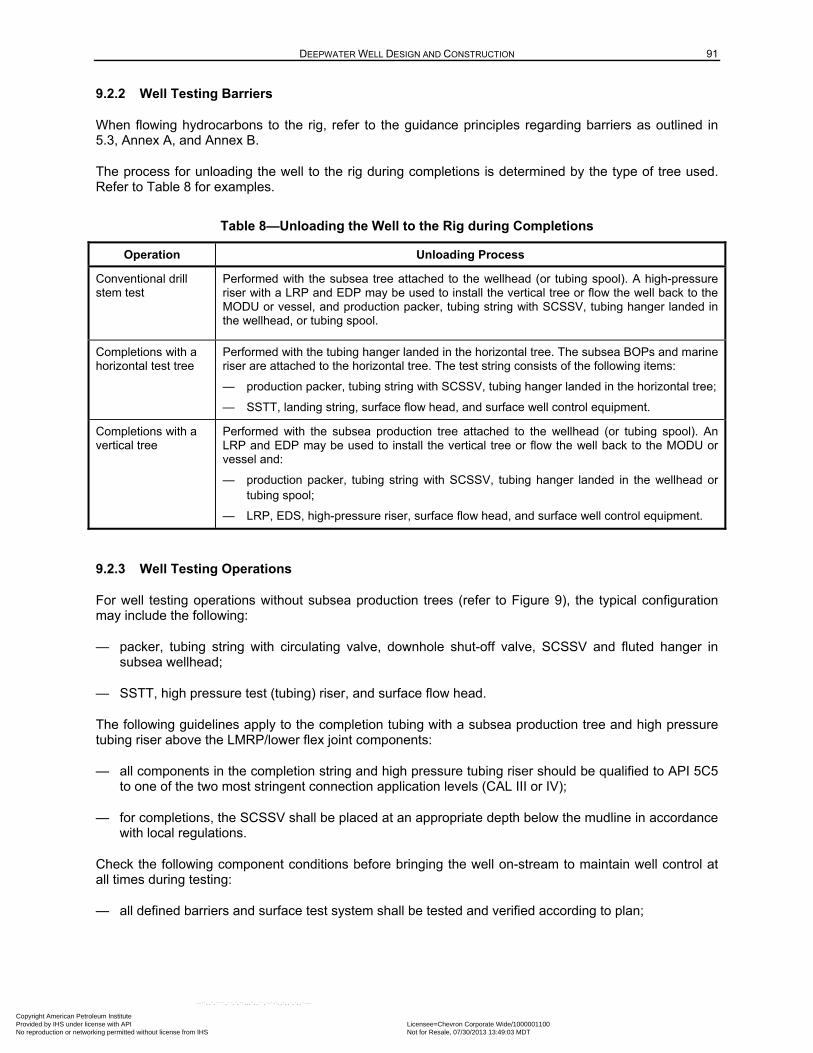
DEEPWATER WELL DESIGN AND CONSTRUCTION 91
9.2.2 Well Testing Barriers
When flowing hydrocarbons to the rig, refer to the guidance principles regarding barriers as outlined in 5.3, Annex A, and Annex B.
The process for unloading the well to the rig during completions is determined by the type of tree used. Refer to Table 8 for examples.
Table 8—Unloading the Well to the Rig during Completions
Operation Unloading Process
Conventional drill stem test
Performed with the subsea tree attached to the wellhead (or tubing spool). A high-pressure riser with a LRP and EDP may be used to install the vertical tree or flow the well back to the MODU or vessel, and production packer, tubing string with SCSSV, tubing hanger landed in the wellhead, or tubing spool.
Completions with a horizontal test tree
Performed with the tubing hanger landed in the horizontal tree. The subsea BOPs and marine riser are attached to the horizontal tree. The test string consists of the following items:
— production packer, tubing string with SCSSV, tubing hanger landed in the horizontal tree;
— SSTT, landing string, surface flow head, and surface well control equipment.
Completions with a vertical tree
Performed with the subsea production tree attached to the wellhead (or tubing spool). An LRP and EDP may be used to install the vertical tree or flow the well back to the MODU or vessel and:
— production packer, tubing string with SCSSV, tubing hanger landed in the wellhead or tubing spool;
— LRP, EDS, high-pressure riser, surface flow head, and surface well control equipment.
9.2.3 Well Testing Operations
For well testing operations without subsea production trees (refer to Figure 9), the typical configuration may include the following:
— packer, tubing string with circulating valve, downhole shut-off valve, SCSSV and fluted hanger in subsea wellhead;
— SSTT, high pressure test (tubing) riser, and surface flow head.
The following guidelines apply to the completion tubing with a subsea production tree and high pressure tubing riser above the LMRP/lower flex joint components:
— all components in the completion string and high pressure tubing riser should be qualified to API 5C5 to one of the two most stringent connection application levels (CAL III or IV);
— for completions, the SCSSV shall be placed at an appropriate depth below the mudline in accordance with local regulations.
Check the following component conditions before bringing the well on-stream to maintain well control at all times during testing:
— all defined barriers and surface test system shall be tested and verified according to plan;
Copyright American Petroleum Institute Provided by IHS under license with API Licensee=Chevron Corporate Wide/1000001100
Not for Resale, 07/30/2013 13:49:03 MDTNo reproduction or networking permitted without license from IHS
--``,,`,````,``,`,``,,,`,,``,`-`-`,,`,,`,`,,`---
92 API RECOMMENDED PRACTICE 96
— the SSTT shall be positioned so that the BSR can be closed, shearing the shear joint and sealing the well;
— if using a dynamically positioned rig, review the EDS relative to the SSTT disconnect or shear.
9.2.4 Surface Well Control Components
9.2.4.1 Surface Flow Head
A typical arrangement for a surface flow head is shown in Figure 10. The surface flow head provides well control to the test string during flowback to surface.
9.2.4.2 Slickline, Wireline, and Coil Tubing
9.2.4.2.1 General
When wireline and/or coil tubing is used during operations, additional lubricator valves and surface wireline/coiled tubing unit BOP systems are installed on top of the surface flow head.
9.2.4.2.2 Slickline
Slickline rig-up uses the following components:
— stuffing box, including a blowout plug or a ball check valve (for live well intervention);
— tool catcher;
— lubricator;
— cable ram (maintaining pressure from below);
— shear seal ram (independent hydraulic operated for live well intervention).
9.2.4.2.3 Wireline
A braided or electric line rig-up consists of the following:
— packoff head for dead well intervention or grease injection head for live well intervention, including integral ball check valve and a minimum of three each flow tubes;
— tool catcher;
— lubricator;
— cable ram (maintaining pressure from below);
— cable ram (maintaining pressure from above);
— shear seal ram (independent hydraulic operated for live well intervention).
Copyright American Petroleum Institute Provided by IHS under license with API Licensee=Chevron Corporate Wide/1000001100
Not for Resale, 07/30/2013 13:49:03 MDTNo reproduction or networking permitted without license from IHS
--``,,`,````,``,`,``,,,`,,``,`-`-`,,`,,`,`,,`---
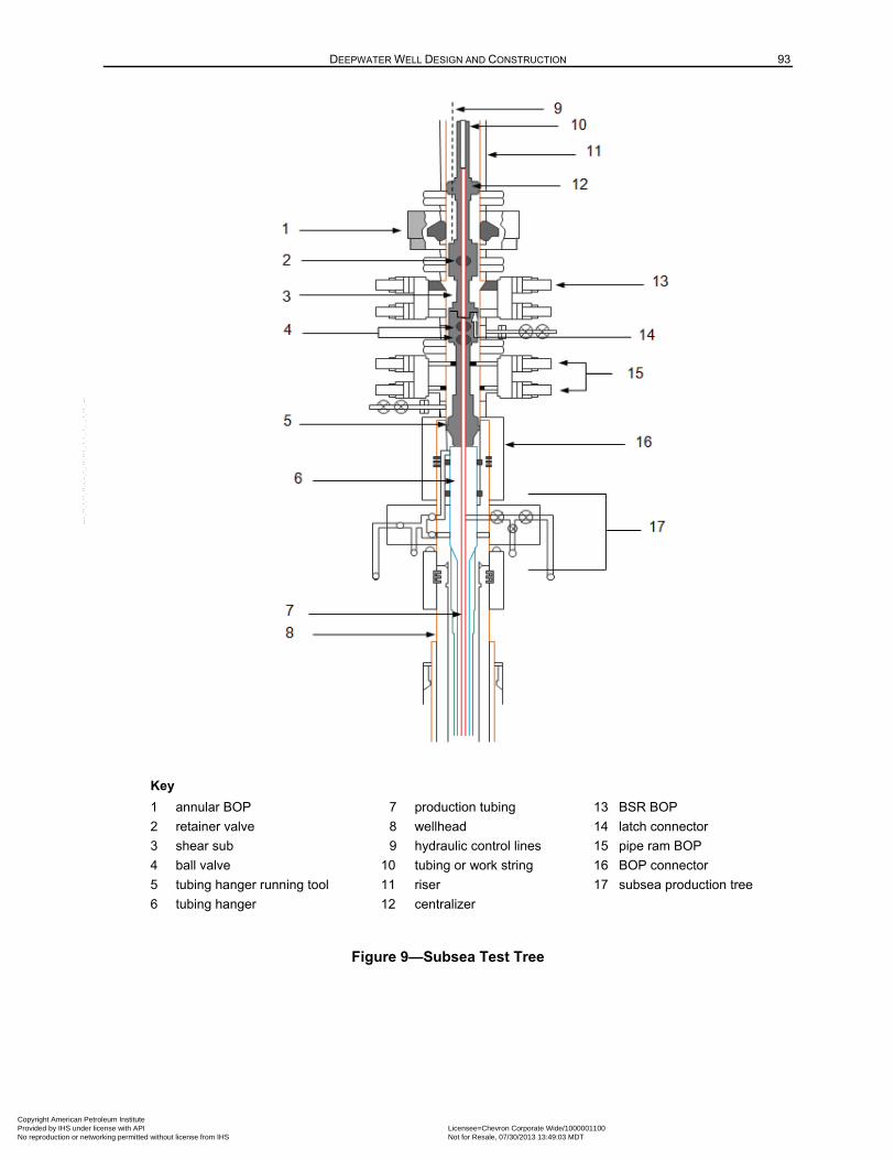
DEEPWATER WELL DESIGN AND CONSTRUCTION 93
Key
1 annular BOP 7 production tubing 13 BSR BOP
2 retainer valve 8 wellhead 14 latch connector
3 shear sub 9 hydraulic control lines 15 pipe ram BOP
4 ball valve 10 tubing or work string 16 BOP connector
5 tubing hanger running tool 11 riser 17 subsea production tree
6 tubing hanger 12 centralizer
Figure 9—Subsea Test Tree
Copyright American Petroleum Institute Provided by IHS under license with API Licensee=Chevron Corporate Wide/1000001100
Not for Resale, 07/30/2013 13:49:03 MDTNo reproduction or networking permitted without license from IHS
--``,,`,````,``,`,``,,,`,,``,`-`-`,,`,,`,`,,`---
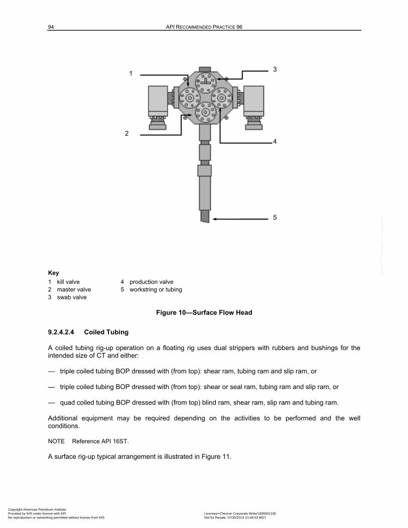
94 API RECOMMENDED PRACTICE 96
Key
1 kill valve 4 production valve 2 master valve 5 workstring or tubing 3 swab valve
Figure 10—Surface Flow Head
9.2.4.2.4 Coiled Tubing
A coiled tubing rig-up operation on a floating rig uses dual strippers with rubbers and bushings for the intended size of CT and either:
— triple coiled tubing BOP dressed with (from top): shear ram, tubing ram and slip ram, or
— triple coiled tubing BOP dressed with (from top): shear or seal ram, tubing ram and slip ram, or
— quad coiled tubing BOP dressed with (from top) blind ram, shear ram, slip ram and tubing ram.
Additional equipment may be required depending on the activities to be performed and the well conditions.
NOTE Reference API 16ST.
A surface rig-up typical arrangement is illustrated in Figure 11.
1
2
3
4
5
Copyright American Petroleum Institute Provided by IHS under license with API Licensee=Chevron Corporate Wide/1000001100
Not for Resale, 07/30/2013 13:49:03 MDTNo reproduction or networking permitted without license from IHS
--``,,`,````,``,`,``,,,`,,``,`-`-`,,`,,`,`,,`---
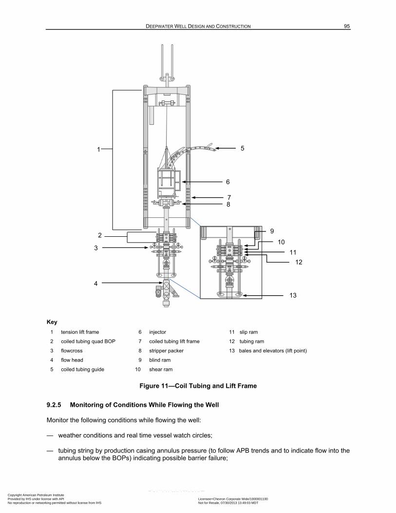
DEEPWATER WELL DESIGN AND CONSTRUCTION 95
Key
1 tension lift frame 6 injector 11 slip ram
2 coiled tubing quad BOP 7 coiled tubing lift frame 12 tubing ram
3 flowcross 8 stripper packer 13 bales and elevators (lift point)
4 flow head 9 blind ram
5 coiled tubing guide 10 shear ram
Figure 11—Coil Tubing and Lift Frame
9.2.5 Monitoring of Conditions While Flowing the Well
Monitor the following conditions while flowing the well:
— weather conditions and real time vessel watch circles;
— tubing string by production casing annulus pressure (to follow APB trends and to indicate flow into the annulus below the BOPs) indicating possible barrier failure;
1
3
13
5
6
7 8
9
10
11
12
4
2
Copyright American Petroleum Institute Provided by IHS under license with API Licensee=Chevron Corporate Wide/1000001100
Not for Resale, 07/30/2013 13:49:03 MDTNo reproduction or networking permitted without license from IHS
--``,,`,````,``,`,``,,,`,,``,`-`-`,,`,,`,`,,`---
96 API RECOMMENDED PRACTICE 96
— trip tank level (flow into annulus above the BOPs);
— rig position to maintain ability to disconnect in the event of a loss of stationkeeping capability;
— hydrate formation (surface or downhole).
Monitor the annulus pressure and trip tank level during flowing and shut-in periods. The test set-up should provide the ability to reverse circulate from the annulus into the tubing string below the BOPs and also to bleed off fluid to a calibrated tank.
Prepare operation plans for these scenarios:
— killing the well;
— preventing hydrate formation;
— providing safety guidelines for personnel if H2S is present in the well stream;
— equipment meets H2S requirements, if applicable.
9.2.6 Floating Rig Motions
Provide appropriate rig motion compensation for the surface flow head, surface well control equipment, and high pressure riser. These components may be supported by a tension lift frame suspended from the rig’s motion compensated hoisting system.
NOTE The proximity of the surface flow head and flowlines to the drill floor can also limit allowable rig offset, and it is considered in developing watch circles for well flowback/testing operations.
9.3 Preproduction Start-up Review
9.3.1 Completions to Production Handover Documentation
Documentation should accompany the handover of the well from completion to production personnel.
The handover documentation should include but not be limited to the following:
a) “A” annulus operation guidelines, to include
— pressure maintenance or not,
— packer fluid type and density,
— packer fluid volume bled during cleanup operations,
— SCSSV operation,
— downhole equipment differential pressure ratings,
— operational limits for annular pressure;
b) final as-built well schematic to include specifications for casing, tubing, and any other downhole equipment in well;
Copyright American Petroleum Institute Provided by IHS under license with API Licensee=Chevron Corporate Wide/1000001100
Not for Resale, 07/30/2013 13:49:03 MDTNo reproduction or networking permitted without license from IHS
--``,,`,````,``,`,``,,,`,,``,`-`-`,,`,,`,`,,`---

DEEPWATER WELL DESIGN AND CONSTRUCTION 97
c) subsea production tree schematics, certifications for tree valves and the final disposition of valves (i.e. open, closed, locked-out) at turn over from rig operations;
d) fluid type and density left in downhole injection and control lines;
e) SCSSV certification papers, operational guidelines and final test data for SCSSV as executed by rig operations during completion operations;
f) records of all pressure tests performed.
10 Management of Change
10.1 Unexpected Events
Unexpected events or circumstances may require a change to the well design during the initial planning process or throughout execution of well construction activities. In some situations, these changes can affect the integrity of the well and/or barriers.
Each operating company shall develop its own practices and policies regarding MOC. The MOCs should be risk assessed, approved at the appropriate level, documented, logged, communicated to the affected parties, tracked while open, and closed when no longer in effect. In some situations, changes to well conditions or equipment may also require regulatory approval to continue operations.
When performing a MOC, the following should be considered:
a) the technical basis for the change;
b) impact of the change on safety, health, and the coastal and marine environments;
c) time to implement the change;
d) management approval procedures for the change;
e) employees, including contractors whose job tasks will be affected by a change in the operation, shall be informed of, and trained in, the change prior to startup of the process or affected part of the operation;
f) if a MOC results in a change in the operating procedures of your SEMS program, such changes shall be documented and dated.
Implementing a MOC process as part of the well planning and execution process, allows a company to effectively manage change(s) to the drilling and completion process. Examples that may use the MOC process are as follows.
a) Failure of equipment used in the original well design.
b) The data in the original well basis of design is no longer valid (e.g. pore pressure or fracture gradient is different than the predrill prediction, which would necessitate a well design change). These changes can result in different loads and design factors for the well, either prior to or during drilling operations.
c) Change in personnel (newly assigned personnel can require additional training to work safely).
Copyright American Petroleum Institute Provided by IHS under license with API Licensee=Chevron Corporate Wide/1000001100
Not for Resale, 07/30/2013 13:49:03 MDTNo reproduction or networking permitted without license from IHS
--``,,`,````,``,`,``,,,`,,``,`-`-`,,`,,`,`,,`---
98 API RECOMMENDED PRACTICE 96
d) Change in well scope; an expendable exploration well changes to a production well or a well designed for production is used as an injection well. Changes shall be managed to maintain well integrity.
In some situations, these problems can ultimately require a change in well design to accomplish the original well objectives or to meet policy/regulatory requirements.
NOTE MOC procedures do not apply to situations involving replacement in kind (such as replacement of one component by another component with the same performance capabilities).
Risk assessments should identify failure modes, consequences, required controls and safeguards and a process by which these risks can be mitigated or managed. These risk management processes shall be used during well design and in planning and execution activities. Risk management is a critical element of the MOC process. API 75 recommends practices for developing safe management programs. Refer to DNV-RP-H101 and the IADC HSE Case Guidelines for more information on risk management.
10.2 Well Contingency Plans
The well engineer generates contingencies during planning to address scenarios that may require a deviation from the original well design. When the options are sufficiently developed and vetted with stakeholders, then the MOC process may use these plans to support the changes.
10.3 Stakeholder Interface
Stakeholder alignment and agreement with well design and procedures, enhances the well delivery process. The well operator interfaces with the rig contractor and other third-party equipment and service suppliers as determined by well-specific information. Interfacing with stakeholders facilitates management of any changes that can occur.
10.4 Stop Work Authority
Stop work authority (SWA) is applicable to both rig operations and well design. The drilling contractor‘s management system for the rig shall include a SWA process with a nonreprisal policy to allow all personnel to freely express their safety concerns. The SWA process provides all operator and contractor/service personnel directly or indirectly involved with the operation the responsibility to pause operations until an appropriate review of the activity can be performed. Operations will resume when safe to continue.
The SWA assigns the responsibility and authorizes an individual to stop the specific task(s) or activity that poses an imminent risk or danger. Imminent risk or danger would mean any condition, activity, or practice in the workplace that could reasonably be expected to cause:
— death or serious physical harm immediately or before the risk or danger can be eliminated through enforcement procedures; or
— significant, imminent environmental harm to land, air, aquatic, marine or subsea environments or resources.
The resolution of a SWA incident may include review by an independent supervisor (in accordance with the operator’s/contractor’s SEMS) and/or implementation of a MOC before operations are resumed. As an example, a SWA process may progress as follows:
— stopping the possible at-risk act, behavior, or event;
— notifying the supervisor or appropriate authority;
Copyright American Petroleum Institute Provided by IHS under license with API Licensee=Chevron Corporate Wide/1000001100
Not for Resale, 07/30/2013 13:49:03 MDTNo reproduction or networking permitted without license from IHS
--``,,`,````,``,`,``,,,`,,``,`-`-`,,`,,`,`,,`---

DEEPWATER WELL DESIGN AND CONSTRUCTION 99
— engaging technical advisors/experts in accordance with operator’s/contractor’s SEMS;
— addressing the issue;
— resuming work;
— documenting the lessons learned.
Copyright American Petroleum Institute Provided by IHS under license with API Licensee=Chevron Corporate Wide/1000001100
Not for Resale, 07/30/2013 13:49:03 MDTNo reproduction or networking permitted without license from IHS
--``,,`,````,``,`,``,,,`,,``,`-`-`,,`,,`,`,,`---
100
Annex A (informative)
Examples of Barriers Employed During Operations
The tables in Annex A represent examples of operations conducted during the drilling and completion of DW wells. The tables list examples of well barriers used in DW wells to maintain control by preventing flow through undesired pathways that are present during that particular operation. The tables provide details about the well barriers. Annex B contains more details about the installation, maintenance, and use of specific example barriers.
This annex is not intended to capture every possible operation or well configuration. The well barriers that are listed represent only one possible configuration, and the tables in this annex do not preclude other configurations of barriers. Similarly, the tabulated verification methods that assist in the determination whether the well barrier was properly installed represent only one way to perform the verification. Users of this document may reference the tables in this annex when developing their own tables for their own operations.
The following examples of various drilling operations are described in this annex:
— drilling ahead (refer to Figure A.1 and Table A.1);
— emergency evacuation/disconnect/BOP repair (LMRP removal only) (refer to Figure A.2 and Table A.2);
— abandonment (full BOP removal) (refer to Figure A.3, Figure A.4, and Table A.3);
— tripping after tubing-conveyed perforating (refer to Figure A.5 and Table A.4);
— flowback through production tubing to rig (refer to Figure A.6 and Table A.5).
Emergency evacuation or some subsea equipment repairs require removing the LMRP and marine riser only. BOP BSRs remain as a physical barrier. However, the hydrostatic barrier can be lost if the fluid density does not include riser margin. This requires reconsideration of the annular and inner-casing flow paths.
Permanent or temporary abandonment operations require removing the BOPs and marine drilling riser. This will result in the loss of at least one and probably two physical barriers (the ability to have a closed BOP and the hydrostatic barrier if the fluid density does not replace the riser margin). Therefore, this operation requires reconsideration of the annular and inner-casing flow paths.
Copyright American Petroleum Institute Provided by IHS under license with API Licensee=Chevron Corporate Wide/1000001100
Not for Resale, 07/30/2013 13:49:03 MDTNo reproduction or networking permitted without license from IHS
--``,,`,````,``,`,``,,,`,,``,`-`-`,,`,,`,`,,`---
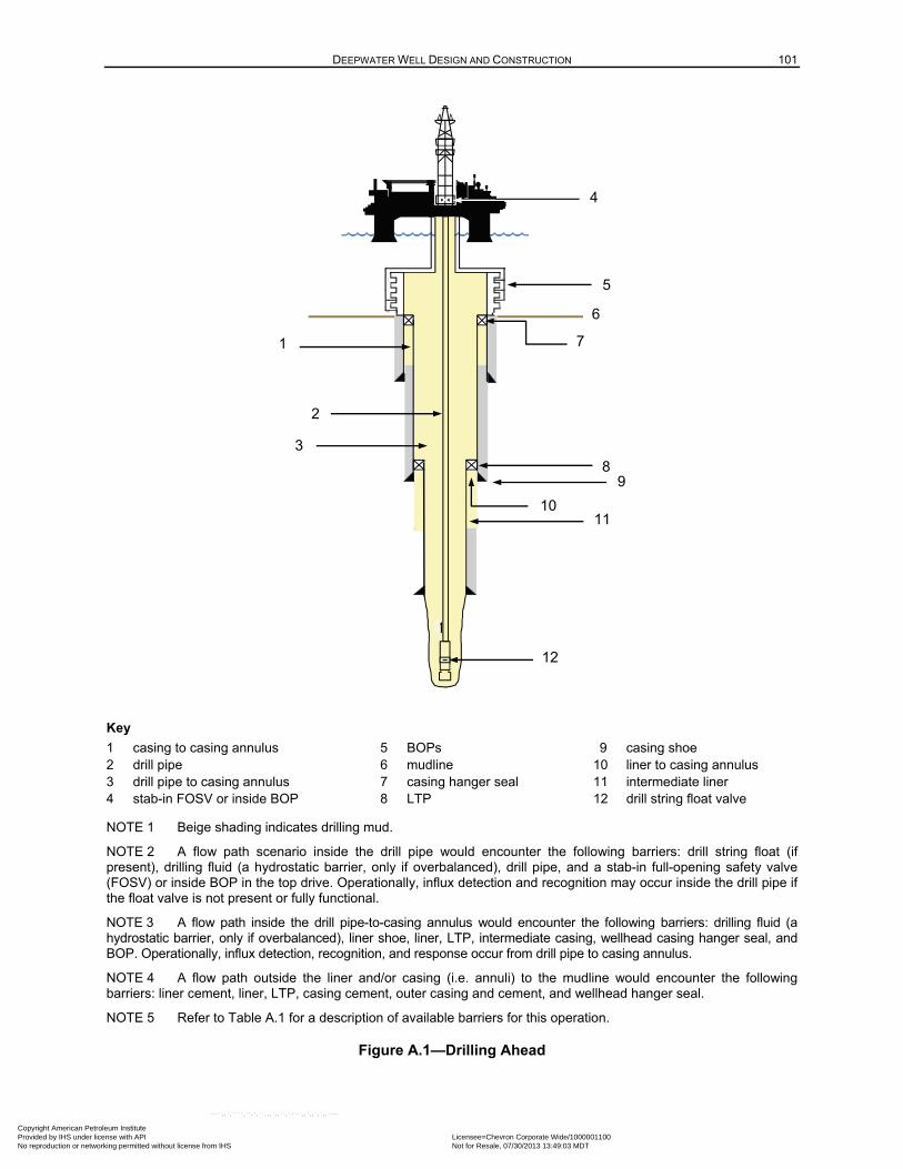
DEEPWATER WELL DESIGN AND CONSTRUCTION 101
Key
1 casing to casing annulus 5 BOPs 9 casing shoe 2 drill pipe 6 mudline 10 liner to casing annulus 3 drill pipe to casing annulus 7 casing hanger seal 11 intermediate liner 4 stab-in FOSV or inside BOP 8 LTP 12 drill string float valve
NOTE 1 Beige shading indicates drilling mud.
NOTE 2 A flow path scenario inside the drill pipe would encounter the following barriers: drill string float (if present), drilling fluid (a hydrostatic barrier, only if overbalanced), drill pipe, and a stab-in full-opening safety valve (FOSV) or inside BOP in the top drive. Operationally, influx detection and recognition may occur inside the drill pipe if the float valve is not present or fully functional.
NOTE 3 A flow path inside the drill pipe-to-casing annulus would encounter the following barriers: drilling fluid (a hydrostatic barrier, only if overbalanced), liner shoe, liner, LTP, intermediate casing, wellhead casing hanger seal, and BOP. Operationally, influx detection, recognition, and response occur from drill pipe to casing annulus.
NOTE 4 A flow path outside the liner and/or casing (i.e. annuli) to the mudline would encounter the following barriers: liner cement, liner, LTP, casing cement, outer casing and cement, and wellhead hanger seal.
NOTE 5 Refer to Table A.1 for a description of available barriers for this operation.
Figure A.1—Drilling Ahead
1
1 1
5
1
2
3
4
11
7
6
10
12
9 8
Copyright American Petroleum Institute Provided by IHS under license with API Licensee=Chevron Corporate Wide/1000001100
Not for Resale, 07/30/2013 13:49:03 MDTNo reproduction or networking permitted without license from IHS
--``,,`,````,``,`,``,,,`,,``,`-`-`,,`,,`,`,,`---
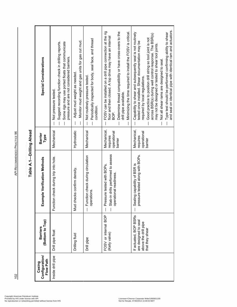
102
AP
I RE
CO
MM
EN
DE
D P
RA
CT
ICE
96
Tab
le A
.1—
Dri
llin
g A
hea
d
Cas
ing
C
on
fig
ura
tio
n/
Flo
w P
ath
Bar
rier
s
(B
ott
om
to
To
p)
Exa
mp
le V
erif
icat
ion
Met
ho
ds
Bar
rier
T
ype
S
pec
ial C
on
sid
erat
ion
s
Insi
de d
rill
pip
e
Dril
l pip
e flo
at
Fun
ctio
n ch
eck
durin
g tr
ip in
to h
ole.
M
echa
nica
l —
Not
pre
ssur
e te
sted
.
— S
ugg
est r
ecor
din
g fu
nctio
n ch
eck
in d
rilli
ng r
epor
ts.
— S
ome
rigs
ma
y us
e po
rted
flo
ats
that
com
mun
icat
e pr
essu
re a
nd
are
not
con
side
red
barr
iers
.
Dril
ling
fluid
M
ud c
heck
s co
nfirm
den
sity
. H
ydro
stat
ic
—
Adj
ust m
ud w
eig
ht a
s ne
ede
d.
—
Mon
itor
mu
d w
eig
ht a
nd g
as u
nits
for
gas
cut m
ud.
Dril
l pip
e —
Fun
ctio
n ch
eck
durin
g ci
rcul
atio
n op
erat
ions
. M
echa
nica
l —
Not
rou
tinel
y pr
essu
re te
sted
.
— P
erio
dica
lly in
spec
ted
for
bod
y, s
eal f
ace,
an
d th
read
co
nditi
on.
FO
SV
or
inte
rnal
BO
P
(Kel
ly v
alve
) —
Pre
ssur
e te
sted
with
BO
Ps.
— S
tab-
in d
rills
per
form
ed to
ass
ess
oper
atio
nal
re
adi
nes
s.
Mec
hani
cal,
requ
ires
oper
atio
nal
ba
rrie
r
— F
OS
V c
an b
e in
stal
led
on
a d
rill p
ipe
conn
ectio
n at
the
rig
floor
an
d th
en c
lose
d. A
top
driv
e m
ay
have
an
inte
rnal
B
OP
.
— D
eter
min
e th
read
com
pat
ibili
ty o
r h
ave
cros
s-ov
ers
to th
e dr
ill p
ipe
avai
labl
e.
— M
inim
izin
g th
e tim
e re
quire
d to
inst
all t
he F
OS
V is
crit
ical
.
If ac
tuat
ed,
BO
P B
SR
s ar
e de
sign
ed t
o se
al
abov
e th
e dr
ill p
ipe
that
the
y sh
ear
— S
ealin
g ca
pabi
lity
of B
SR
is
pres
sure
test
ed a
long
with
BO
Ps.
M
echa
nica
l, re
quire
s op
erat
ion
al
barr
ier
— C
apab
ility
to s
hear
and
su
bseq
uen
tly s
eal
is n
ot r
outin
ely
te
sted
onc
e in
stal
led.
She
ar d
ocum
ent
atio
n m
ay
be
requ
ired
by
loca
l reg
ulat
ions
.
— G
ood
prac
tice
to p
ositi
on d
rill s
trin
g so
tool
join
t is
not
acro
ss B
SR
(s)
durin
g w
ell
cont
rol r
espo
nse.
The
BS
R(s
) m
ay
not
be
de
sign
ed o
r te
ste
d to
she
ar to
ol j
oint
s.
— N
ot a
ll sh
ear
ram
s ar
e de
sign
ed to
sea
l.
— T
ype
test
sho
uld
be p
erfo
rmed
con
firm
ing
abili
ty to
she
ar
and
seal
on
ide
ntic
al p
ipe
with
iden
tical
ram
and
act
uato
rs.
Copyright American Petroleum Institute Provided by IHS under license with API Licensee=Chevron Corporate Wide/1000001100
Not for Resale, 07/30/2013 13:49:03 MDTNo reproduction or networking permitted without license from IHS
--``,,`,````,``,`,``,,,`,,``,`-`-`,,`,,`,`,,`---
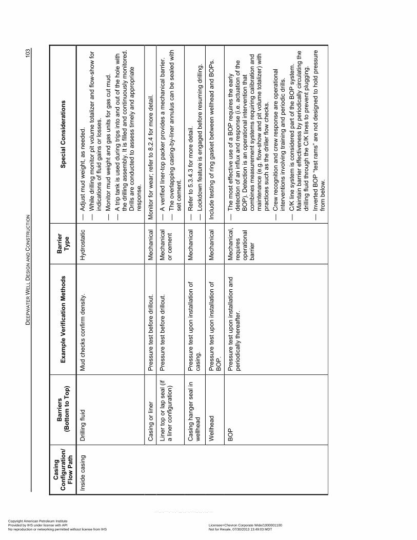
D
EE
PW
AT
ER
WE
LL D
ES
IGN
AN
D C
ON
ST
RU
CT
ION
10
3
Cas
ing
C
on
fig
ura
tio
n/
Flo
w P
ath
Bar
rier
s
(B
ott
om
to
To
p)
Exa
mp
le V
erif
icat
ion
Met
ho
ds
Bar
rier
T
ype
S
pec
ial C
on
sid
erat
ion
s
Insi
de c
asin
g
Dril
ling
fluid
M
ud c
heck
s co
nfirm
den
sity
. H
ydro
stat
ic
— A
djus
t mud
we
ight
, as
nee
ded
.
— W
hile
dri
lling
mon
itor
pit
volu
me
tota
lizer
and
flo
w-s
how
for
in
dica
tions
of f
luid
gai
ns o
r lo
sses
.
— M
onito
r m
ud
wei
ght
and
gas
uni
ts fo
r ga
s cu
t mud
.
— A
trip
tank
is u
sed
duri
ng tr
ips
into
and
out
of t
he h
ole
with
th
e dr
illin
g as
sem
bly.
It is
fille
d an
d co
ntin
uous
ly m
onito
red.
D
rills
are
con
duc
ted
to a
sses
s tim
ely
and
ap
prop
riat
e re
spon
se.
Cas
ing
or li
ner
Pre
ssur
e te
st b
efor
e dr
illou
t. M
echa
nica
l M
onito
r fo
r w
ear
; re
fer
to 8
.2.4
for
mor
e de
tail.
Lin
er to
p or
lap
sea
l (if
a lin
er c
onfig
urat
ion)
P
ress
ure
test
bef
ore
drill
out
. M
echa
nica
l or
cem
ent
— A
ver
ified
line
r-to
p pa
cker
pro
vide
s a
mec
hani
cal b
arri
er.
— T
he o
verla
ppi
ng
casi
ng-
by-
liner
ann
ulus
can
be
seal
ed w
ith
set
cem
ent.
Cas
ing
hang
er s
eal i
n w
ellh
ead
P
ress
ure
test
upo
n in
stal
latio
n o
f ca
sing
.
Mec
hani
cal
— R
efer
to 5
.3.4
.3 fo
r m
ore
deta
il.
— L
ockd
ow
n fe
atur
e is
en
gage
d b
efor
e re
sum
ing
drill
ing.
Wel
lhe
ad
Pre
ssur
e te
st u
pon
inst
alla
tion
of
BO
P.
Mec
hani
cal
Incl
ude
test
ing
of r
ing
gask
et b
etw
een
we
llhea
d a
nd B
OP
s.
BO
P
Pre
ssur
e te
st u
pon
inst
alla
tion
and
pe
riodi
cally
the
reaf
ter.
M
echa
nica
l, re
quire
s op
erat
ion
al
barr
ier
— T
he m
ost e
ffect
ive
use
of a
BO
P r
equi
res
the
earl
y de
tect
ion
of a
n in
flux
and
resp
onse
(i.e
. act
uat
ion
of th
e B
OP
). D
etec
tion
is a
n op
erat
iona
l int
erve
ntio
n th
at
com
bine
s m
easu
rem
ent
sys
tem
s re
quiri
ng c
alib
ratio
n an
d m
aint
ena
nce
(e.g
. flo
w-s
how
and
pit
volu
me
tota
lizer
) w
ith
prac
tices
suc
h as
the
drill
er fl
ow c
heck
s.
— C
rew
rec
ogn
ition
an
d cr
ew
re
spon
se a
re o
per
atio
nal
inte
rve
ntio
ns in
volv
ing
trai
nin
g a
nd p
erio
dic
dril
ls.
— C
/K li
ne s
yste
m is
con
sid
ere
d pa
rt o
f the
BO
P s
yste
m.
Mai
nta
in b
arri
er
effe
ctiv
enes
s b
y pe
riod
ical
ly c
ircul
atin
g th
e dr
illin
g flu
id th
roug
h th
e C
/K li
nes
to p
reve
nt p
lugg
ing.
— I
nver
ted
BO
P “
test
ram
s” a
re n
ot d
esig
ned
to h
old
pres
sure
fr
om b
elo
w.
Copyright American Petroleum Institute Provided by IHS under license with API Licensee=Chevron Corporate Wide/1000001100
Not for Resale, 07/30/2013 13:49:03 MDTNo reproduction or networking permitted without license from IHS
--``,,`,````,``,`,``,,,`,,``,`-`-`,,`,,`,`,,`---
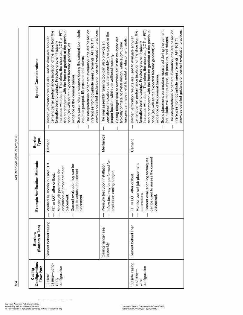
104
AP
I RE
CO
MM
EN
DE
D P
RA
CT
ICE
96
Cas
ing
C
on
fig
ura
tio
n/
Flo
w P
ath
Bar
rier
s
(B
ott
om
to
To
p)
Exa
mp
le V
erif
icat
ion
Met
ho
ds
Bar
rier
T
ype
S
pec
ial C
on
sid
erat
ion
s
Out
side
ca
sing
—Lo
ng-
strin
g co
nfig
urat
ion
Cem
ent
beh
ind
cas
ing
—
Ver
ifie
d as
sho
wn
in T
able
B.3
.
— F
IT o
r LO
T a
fter
drill
out.
— M
onito
r jo
b pa
ram
eter
s fo
r in
dica
tions
of p
rope
r ce
men
t pl
acem
ent.
— C
eme
nt e
valu
atio
n lo
g ca
n b
e us
ed to
ass
ess
the
cem
ent
plac
emen
t.
Cem
ent
—
Bar
rier
verif
icat
ion
resu
lts a
re u
sed
to e
valu
ate
ann
ular
ce
men
t bar
rier
per
form
anc
e (i
sola
tion
of th
e sh
oe fr
om th
e fo
rmat
ion
beh
ind
casi
ng).
Fra
ctur
e gr
adie
nt ty
pic
ally
in
cre
ases
with
dep
th. T
here
fore
, th
e sh
oe te
st (
LOT
or
FIT
) ca
n be
com
pare
d w
ith th
e fr
actu
re g
rad
ient
at t
he p
revi
ous
sh
oe (
as w
ell
as
the
expe
cte
d fr
actu
re g
rad
ient
) as
ev
iden
ce o
f the
cem
ent b
arri
er.
— S
ome
para
met
ers
mea
sure
d du
ring
the
cem
ent j
ob in
clud
e vo
lum
es p
ump
ed, l
ift p
ress
ure
and
retu
rns.
— T
he in
terp
reta
tions
of c
emen
t ev
alua
tion
logs
are
bas
ed
on
infe
renc
es fr
om
do
wn
hole
mea
sure
men
ts. A
PI 1
0TR
1 pr
ovid
es d
etai
led
guid
ance
on
cem
ent e
valu
atio
n pr
actic
es.
Cas
ing
hang
er s
eal
asse
mbl
y —
Pre
ssur
e te
st u
pon
inst
alla
tion
.
— I
nflo
w te
st m
ay b
e pe
rfor
med
for
prod
uctio
n ca
sing
ha
nger
.
Mec
hani
cal
—
The
sea
l ass
em
bly
run
nin
g to
ol c
an
also
pro
vid
e an
op
erat
ion
al in
dica
tion
that
the
asse
mb
ly is
en
gag
ed in
the
prop
er lo
catio
n w
ithin
the
we
llhea
d ho
usin
g.
—
Cas
ing
hang
er s
eal a
ssem
blie
s se
t in
the
we
llhe
ad a
re
typi
cally
of m
etal
to m
etal
des
ign,
whi
le s
ubm
udlin
e ha
nge
rs c
an
hav
e m
etal
to m
etal
or
elas
tom
eric
sea
ls.
Out
side
cas
ing
an
d lin
er—
Lin
er
conf
igur
atio
n
Cem
ent
beh
ind
line
r
— F
IT o
r LO
T a
fter
drill
out.
— M
onito
r ce
men
t jo
b pl
acem
ent
pa
ram
eter
s.
— C
eme
nt e
valu
atio
n lo
g te
chn
ique
s ca
n be
use
d to
ass
ess
the
cem
ent
plac
emen
t.
Cem
ent
—
Bar
rier
verif
icat
ion
resu
lts a
re u
sed
to e
valu
ate
ann
ular
ce
men
t bar
rier
per
form
anc
e (i
sola
tion
of th
e sh
oe fr
om th
e fo
rmat
ion
beh
ind
casi
ng).
Fra
ctur
e gr
adie
nt ty
pic
ally
in
cre
ases
with
dep
th. T
here
fore
, th
e sh
oe te
st (
LOT
or
FIT
) ca
n be
com
pare
d w
ith th
e fr
actu
re g
rad
ient
at t
he p
revi
ous
sh
oe (
as w
ell
as
the
expe
cte
d fr
actu
re g
rad
ient
) as
ev
iden
ce o
f the
cem
ent b
arri
er.
— S
ome
plac
eme
nt p
aram
eter
s m
easu
red
dur
ing
the
cem
ent
jo
b in
clu
de v
olu
mes
pum
ped,
lift
pres
sure
, and
ret
urns
.
— T
he in
terp
reta
tions
of c
emen
t ev
alua
tion
logs
are
bas
ed
on
infe
renc
es fr
om
do
wn
hole
mea
sure
men
ts. A
PI 1
0TR
1 pr
ovid
es d
etai
led
guid
ance
on
cem
ent e
valu
atio
n pr
actic
es.
Copyright American Petroleum Institute Provided by IHS under license with API Licensee=Chevron Corporate Wide/1000001100
Not for Resale, 07/30/2013 13:49:03 MDTNo reproduction or networking permitted without license from IHS
--``,,`,````,``,`,``,,,`,,``,`-`-`,,`,,`,`,,`---
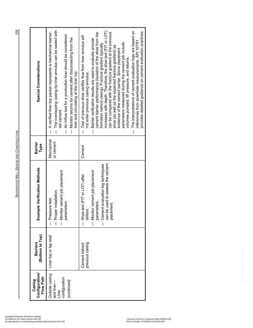
D
EE
PW
AT
ER
WE
LL D
ES
IGN
AN
D C
ON
ST
RU
CT
ION
10
5
Cas
ing
C
on
fig
ura
tio
n/
Flo
w P
ath
Bar
rier
s
(B
ott
om
to
To
p)
Exa
mp
le V
erif
icat
ion
Met
ho
ds
Bar
rier
T
ype
S
pec
ial C
on
sid
erat
ion
s
Out
side
cas
ing
an
d lin
er—
Lin
er
conf
igur
atio
n
(con
tinue
d)
Lin
er to
p or
lap
sea
l —
Pre
ssur
e te
st.
— P
rope
r in
stal
latio
n.
— M
onito
r ce
men
t jo
b pl
acem
ent
pa
ram
eter
s.
Mec
hani
cal
or c
emen
t —
A v
erifi
ed li
ner-
top
pack
er r
epr
esen
ts a
mec
han
ical
bar
rier
.
— T
he o
verla
ppi
ng
casi
ng-
by-
liner
ann
ulus
can
be
seal
ed w
ith
set
cem
ent.
— A
n in
flow
test
for
a pr
oduc
tion
line
r sh
ould
be
con
sid
ered
.
— M
onito
r re
turn
s fo
r ce
men
t afte
r di
sco
nnec
ting
from
the
liner
and
circ
ulat
ing
at th
e lin
er
top.
Cem
ent
beh
ind
pr
evio
us c
asin
g —
Sho
e te
st (
FIT
or
LOT
) af
ter
drill
out.
— M
onito
r ce
men
t jo
b pl
acem
ent
pa
ram
eter
s.
— C
eme
nt e
valu
atio
n lo
g te
chn
ique
s ca
n be
use
d to
ass
ess
the
cem
ent
plac
emen
t.
Cem
ent
—
Tes
t of p
revi
ous
shoe
ver
ifies
flo
w fr
om li
ner
ann
ulus
will
no
t ent
er p
revi
ous
casi
ng a
nnul
us.
— B
arrie
r ve
rific
atio
n re
sults
are
use
d to
eva
luat
e an
nul
ar
cem
ent b
arri
er p
erfo
rma
nce
(iso
latio
n of
the
shoe
from
the
form
atio
n b
ehin
d ca
sing
). F
ract
ure
grad
ient
typ
ical
ly
incr
eas
es w
ith d
epth
. The
refo
re,
the
shoe
test
(F
IT o
r LO
T)
can
be c
ompa
red
with
the
frac
ture
gra
die
nt a
t the
pre
vio
us
shoe
(as
we
ll a
s th
e ex
pect
ed
frac
ture
gra
die
nt)
as
evid
ence
of t
he c
emen
t bar
rier
. Som
e pl
acem
ent
para
met
ers
me
asur
ed
duri
ng t
he c
eme
nt jo
b in
clu
de
volu
mes
pum
ped
, lift
pre
ssur
e, a
nd r
etur
ns.
— T
he in
terp
reta
tions
of c
emen
t ev
alua
tion
logs
are
bas
ed
on
infe
renc
es fr
om
do
wn
hole
mea
sure
men
ts. A
PI 1
0TR
1 pr
ovid
es d
etai
led
guid
ance
on
cem
ent e
valu
atio
n pr
actic
es.
Copyright American Petroleum Institute Provided by IHS under license with API Licensee=Chevron Corporate Wide/1000001100
Not for Resale, 07/30/2013 13:49:03 MDTNo reproduction or networking permitted without license from IHS
--``,,`,````,``,`,``,,,`,,``,`-`-`,,`,,`,`,,`---
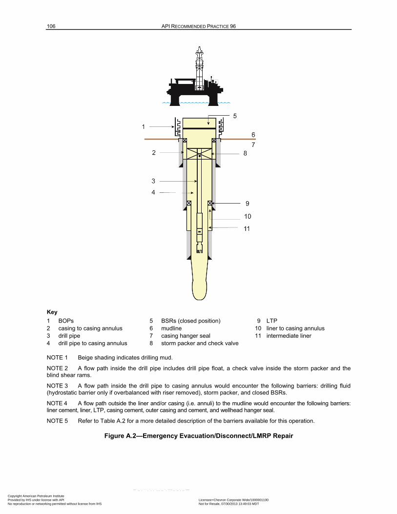
106 API RECOMMENDED PRACTICE 96
Key
1 BOPs 5 BSRs (closed position) 9 LTP 2 casing to casing annulus 6 mudline 10 liner to casing annulus 3 drill pipe 7 casing hanger seal 11 intermediate liner
4 drill pipe to casing annulus 8 storm packer and check valve
NOTE 1 Beige shading indicates drilling mud.
NOTE 2 A flow path inside the drill pipe includes drill pipe float, a check valve inside the storm packer and the blind shear rams.
NOTE 3 A flow path inside the drill pipe to casing annulus would encounter the following barriers: drilling fluid (hydrostatic barrier only if overbalanced with riser removed), storm packer, and closed BSRs.
NOTE 4 A flow path outside the liner and/or casing (i.e. annuli) to the mudline would encounter the following barriers: liner cement, liner, LTP, casing cement, outer casing and cement, and wellhead hanger seal.
NOTE 5 Refer to Table A.2 for a more detailed description of the barriers available for this operation.
Figure A.2—Emergency Evacuation/Disconnect/LMRP Repair
Copyright American Petroleum Institute Provided by IHS under license with API Licensee=Chevron Corporate Wide/1000001100
Not for Resale, 07/30/2013 13:49:03 MDTNo reproduction or networking permitted without license from IHS
--``,,`,````,``,`,``,,,`,,``,`-`-`,,`,,`,`,,`---
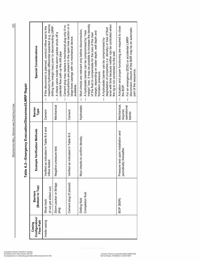
D
EE
PW
AT
ER
WE
LL D
ES
IGN
AN
D C
ON
ST
RU
CT
ION
10
7
Tab
le A
.2—
Em
erg
ency
Eva
cuat
ion
/Dis
con
nec
t/L
MR
P R
epai
r
Cas
ing
C
on
fig
ura
tio
n/
Flo
w P
ath
Bar
rier
s
(Bo
tto
m t
o T
op
) E
xam
ple
Ver
ific
atio
n M
eth
od
s B
arri
er
Typ
e
Sp
ecia
l Co
nsi
der
atio
ns
Insi
de c
asin
g
Sho
e tr
ack
(if n
ot y
et d
rille
d ou
t)
Ver
ifie
d as
ind
icat
ed in
Tab
le B
.4 a
nd
inflo
w t
este
d.
Cem
ent
—
If t
he d
isco
nne
ct is
pla
nned
, con
duc
t inf
low
tes
t to
the
max
imum
hyd
rost
atic
diff
eren
tial e
xpec
ted
(e.g
. mar
ine
drill
ing
riser
ma
rgin
loss
) pr
ior
to d
isco
nne
ctin
g LM
RP
.
— A
che
ck v
alve
insi
de th
e st
orm
pac
ker
shut
s of
f a
pote
ntia
l flo
w p
ath
up th
e dr
ill p
ipe.
— C
eme
nt p
lug
ma
y re
plac
e a
mec
hani
cal p
lug
only
if n
o h
ydro
carb
ons
are
pre
sent
in t
he o
pen
hol
e se
ctio
n or
in
larg
e-bo
re c
asin
gs w
ith n
o m
ech
anic
al d
evic
e av
aila
ble
.
Sto
rm p
acke
r o
r B
ridge
pl
ug
Neg
ativ
e pr
essu
re te
st.
Mec
hani
cal
Cem
ent
plu
g (if
pla
ced)
V
erifi
ed
as in
dic
ated
in T
able
B.5
. C
eme
nt
Dril
ling
fluid
Com
plet
ion
fluid
Mud
che
cks
to c
onfir
m d
ensi
ty.
Hyd
rost
atic
—
Mud
che
cks
are
rele
vant
onl
y be
fore
dis
conn
ectio
n.
— A
hyd
rost
atic
bar
rier
can
be c
ompr
omis
ed b
y “r
iser
m
argi
n” lo
ss. I
t ma
y b
e po
ssib
le to
incr
eas
e th
e de
nsity
of
the
fluid
to c
ompe
nsat
e fo
r th
e lo
ss o
f the
ris
er
mar
gin,
dep
endi
ng
on w
ater
dep
th,
we
ll d
epth
and
fo
rmat
ion
pres
sure
.
— A
hyd
rost
atic
bar
rier
can
be c
ompr
omis
ed b
y de
grad
atio
n of
pro
per
ties
(i.e.
den
sity
) or
loss
of f
luid
le
vel w
ith ti
me
beca
use
nei
the
r ca
n be
con
tro
lled
wh
en
the
rig is
not
co
nnec
ted
to th
e w
ell.
BO
P (
BS
R)
Pre
ssur
e te
st u
pon
inst
alla
tion
and
pe
riodi
cally
the
reaf
ter.
M
echa
nica
l, re
quire
s op
erat
ion
al
barr
ier
— A
ctua
tion
and
pro
per
func
tion
ing
are
req
uire
d to
clo
se
the
BO
P.
— F
or a
n em
erg
enc
y (E
DS
) or
acc
ide
ntal
LM
RP
di
sco
nnec
t, cl
osu
re o
f the
BS
R m
ay
be
an a
utom
atic
pa
rt o
f the
seq
uenc
e.
Copyright American Petroleum Institute Provided by IHS under license with API Licensee=Chevron Corporate Wide/1000001100
Not for Resale, 07/30/2013 13:49:03 MDTNo reproduction or networking permitted without license from IHS
--``,,`,````,``,`,``,,,`,,``,`-`-`,,`,,`,`,,`---
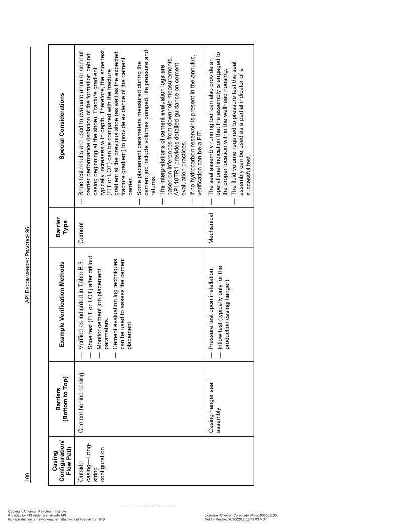
108
AP
I RE
CO
MM
EN
DE
D P
RA
CT
ICE
96
Cas
ing
C
on
fig
ura
tio
n/
Flo
w P
ath
Bar
rier
s
(Bo
tto
m t
o T
op
) E
xam
ple
Ver
ific
atio
n M
eth
od
s B
arri
er
Typ
e
Sp
ecia
l Co
nsi
der
atio
ns
Out
side
ca
sing
—Lo
ng-
strin
g co
nfig
urat
ion
Cem
ent
beh
ind
cas
ing
—
Ver
ifie
d as
ind
icat
ed in
Tab
le B
.3.
— S
hoe
test
(F
IT o
r LO
T)
afte
r dr
illo
ut
— M
onito
r ce
men
t jo
b pl
acem
ent
pa
ram
eter
s.
— C
eme
nt e
valu
atio
n lo
g te
chn
ique
s ca
n be
use
d to
ass
ess
the
cem
ent
plac
emen
t.
Cem
ent
—
Sho
e te
st r
esu
lts a
re u
sed
to e
valu
ate
ann
ula
r ce
men
t ba
rrie
r pe
rfor
man
ce (
isol
atio
n of
the
form
atio
n be
hin
d ca
sin
g be
gin
ning
at t
he s
hoe)
. F
ract
ure
grad
ient
ty
pica
lly in
cre
ase
s w
ith d
ept
h. T
here
fore
, the
sho
e te
st
(FIT
or
LOT
) ca
n be
com
pare
d w
ith th
e fr
actu
re
grad
ient
at t
he p
revi
ous
sho
e (a
s w
ell
as th
e ex
pect
ed
frac
ture
gra
die
nt)
to p
rovi
de e
vide
nce
of th
e ce
men
t ba
rrie
r.
— S
ome
plac
eme
nt p
aram
eter
s m
easu
red
dur
ing
the
cem
ent j
ob
incl
ude
volu
mes
pum
ped,
life
pre
ssur
e an
d re
turn
s.
— T
he in
terp
reta
tions
of c
emen
t ev
alua
tion
logs
are
ba
sed
on in
fere
nces
from
do
wn
hol
e m
eas
urem
ents
. A
PI 1
0TR
1 pr
ovid
es d
etai
led
guid
ance
on
cem
ent
eval
uatio
n pr
actic
es.
— I
f no
hyd
roca
rbon
res
ervo
ir is
pre
sent
in th
e an
nul
us,
verif
icat
ion
can
be
a F
IT.
Cas
ing
hang
er s
eal
asse
mbl
y —
Pre
ssur
e te
st u
pon
inst
alla
tion
.
— I
nflo
w t
est
(typ
ical
ly o
nly
for
the
prod
uctio
n ca
sing
ha
nger
).
Mec
hani
cal
— T
he s
eal a
sse
mbl
y ru
nni
ng
tool
ca
n al
so p
rovi
de
an
oper
atio
nal
indi
catio
n th
at th
e as
sem
bly
is e
nga
ged
to
the
prop
er lo
catio
n w
ithin
the
we
llhe
ad h
ousi
ng.
— T
he fl
uid
volu
me
requ
ired
to p
ress
ure
test
the
sea
l as
sem
bly
can
be
use
d as
a p
artia
l ind
icat
or o
f a
succ
essf
ul t
est.
Copyright American Petroleum Institute Provided by IHS under license with API Licensee=Chevron Corporate Wide/1000001100
Not for Resale, 07/30/2013 13:49:03 MDTNo reproduction or networking permitted without license from IHS
--``,,`,````,``,`,``,,,`,,``,`-`-`,,`,,`,`,,`---
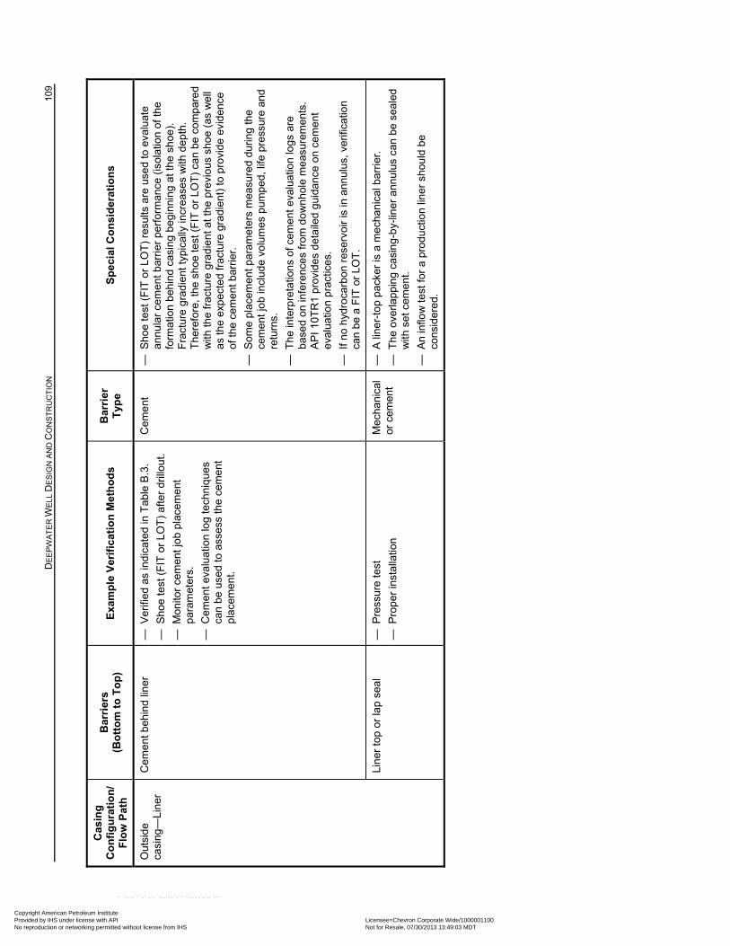
D
EE
PW
AT
ER
WE
LL D
ES
IGN
AN
D C
ON
ST
RU
CT
ION
10
9
Cas
ing
C
on
fig
ura
tio
n/
Flo
w P
ath
Bar
rier
s
(Bo
tto
m t
o T
op
) E
xam
ple
Ver
ific
atio
n M
eth
od
s B
arri
er
Typ
e
Sp
ecia
l Co
nsi
der
atio
ns
Out
side
ca
sing
—Li
ner
Cem
ent
beh
ind
line
r —
Ver
ifie
d as
ind
icat
ed in
Tab
le B
.3.
— S
hoe
test
(F
IT o
r LO
T)
afte
r dr
illo
ut.
— M
onito
r ce
men
t jo
b pl
acem
ent
pa
ram
eter
s.
— C
eme
nt e
valu
atio
n lo
g te
chn
ique
s ca
n be
use
d to
ass
ess
the
cem
ent
plac
emen
t.
Cem
ent
—
Sho
e te
st (
FIT
or
LOT
) re
sults
are
use
d to
eva
luat
e an
nul
ar c
emen
t ba
rrie
r pe
rfor
man
ce (
isol
atio
n of
the
form
atio
n b
ehin
d ca
sing
beg
inni
ng a
t the
sh
oe).
F
ract
ure
grad
ient
typi
cally
incr
ease
s w
ith d
ep
th.
The
refo
re, t
he s
hoe
test
(F
IT o
r LO
T)
can
be c
ompa
red
with
the
frac
ture
gra
die
nt a
t th
e pr
evio
us s
ho
e (a
s w
ell
as th
e e
xpec
ted
frac
ture
gra
die
nt)
to p
rovi
de
evid
ence
of
the
cem
ent b
arrie
r.
— S
ome
plac
eme
nt p
aram
eter
s m
easu
red
dur
ing
the
cem
ent j
ob
incl
ude
volu
mes
pum
ped,
life
pre
ssur
e an
d re
turn
s.
— T
he in
terp
reta
tions
of c
emen
t ev
alua
tion
logs
are
ba
sed
on in
fere
nces
from
do
wn
hol
e m
eas
urem
ents
. A
PI 1
0TR
1 pr
ovid
es d
etai
led
guid
ance
on
cem
ent
eval
uatio
n pr
actic
es.
— I
f no
hyd
roca
rbon
res
ervo
ir is
in a
nnul
us, v
erifi
catio
n ca
n be
a F
IT o
r LO
T.
Lin
er to
p or
lap
sea
l —
Pre
ssur
e te
st
— P
rope
r in
stal
latio
n
Mec
hani
cal
or c
emen
t —
A li
ner-
top
pack
er is
a m
echa
nica
l bar
rier
.
— T
he o
verla
ppi
ng
casi
ng-
by-
liner
ann
ulus
can
be
seal
ed
with
set
cem
ent.
— A
n in
flow
test
for
a pr
oduc
tion
line
r sh
ould
be
co
nsid
ere
d.
Copyright American Petroleum Institute Provided by IHS under license with API Licensee=Chevron Corporate Wide/1000001100
Not for Resale, 07/30/2013 13:49:03 MDTNo reproduction or networking permitted without license from IHS
--``,,`,````,``,`,``,,,`,,``,`-`-`,,`,,`,`,,`---
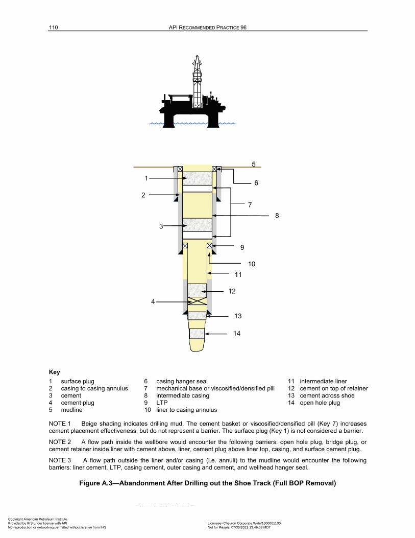
110 API RECOMMENDED PRACTICE 96
Key
1 surface plug 6 casing hanger seal 11 intermediate liner 2 casing to casing annulus 7 mechanical base or viscosified/densified pill 12 cement on top of retainer 3 cement 8 intermediate casing 13 cement across shoe 4 cement plug 9 LTP 14 open hole plug 5 mudline 10 liner to casing annulus
NOTE 1 Beige shading indicates drilling mud. The cement basket or viscosified/densified pill (Key 7) increases cement placement effectiveness, but do not represent a barrier. The surface plug (Key 1) is not considered a barrier.
NOTE 2 A flow path inside the wellbore would encounter the following barriers: open hole plug, bridge plug, or cement retainer inside liner with cement above, liner, cement plug above liner top, casing, and surface cement plug.
NOTE 3 A flow path outside the liner and/or casing (i.e. annuli) to the mudline would encounter the following barriers: liner cement, LTP, casing cement, outer casing and cement, and wellhead hanger seal.
Figure A.3—Abandonment After Drilling out the Shoe Track (Full BOP Removal)
5
4
1
2
3
6
8
12
11
10
14
9
7
13
Copyright American Petroleum Institute Provided by IHS under license with API Licensee=Chevron Corporate Wide/1000001100
Not for Resale, 07/30/2013 13:49:03 MDTNo reproduction or networking permitted without license from IHS
--``,,`,````,``,`,``,,,`,,``,`-`-`,,`,,`,`,,`---
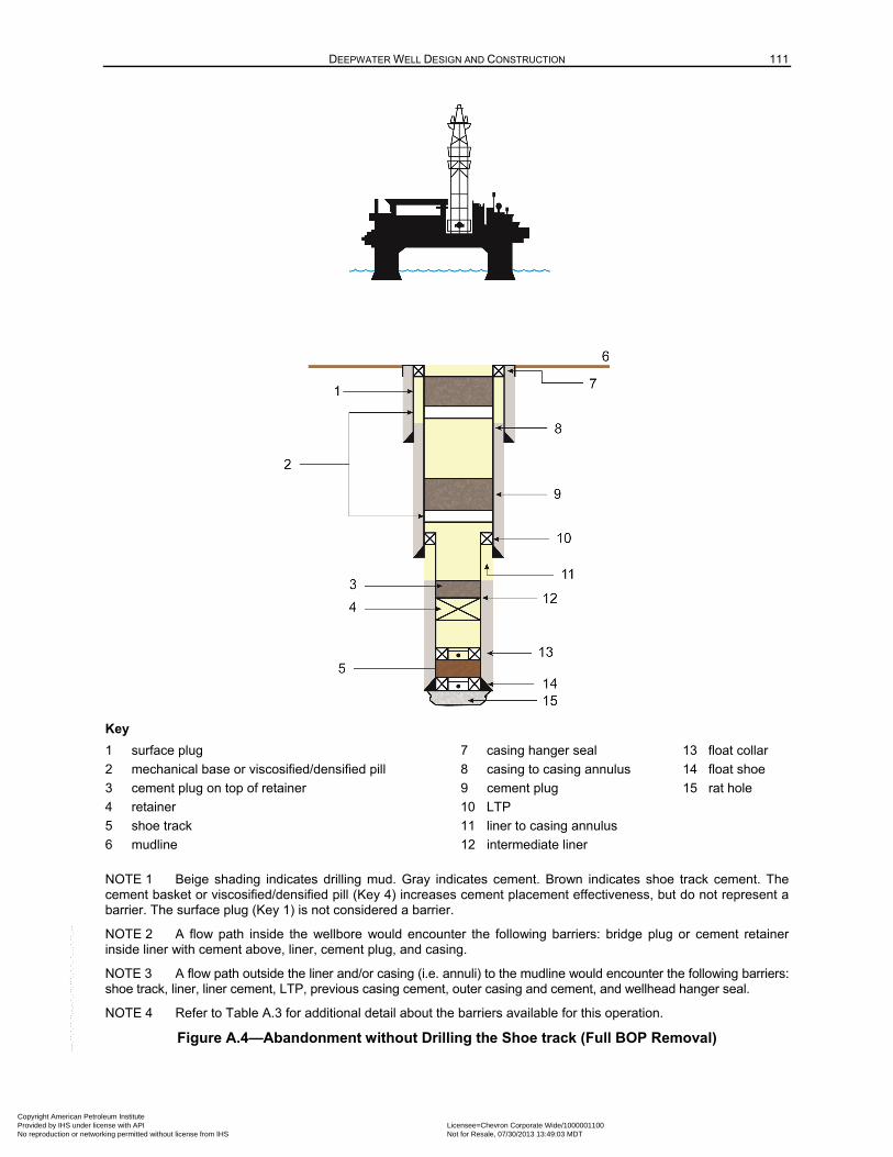
DEEPWATER WELL DESIGN AND CONSTRUCTION 111
Key
1 surface plug 7 casing hanger seal 13 float collar
2 mechanical base or viscosified/densified pill 8 casing to casing annulus 14 float shoe
3 cement plug on top of retainer 9 cement plug 15 rat hole
4 retainer 10 LTP
5 shoe track 11 liner to casing annulus
6 mudline 12 intermediate liner
NOTE 1 Beige shading indicates drilling mud. Gray indicates cement. Brown indicates shoe track cement. The cement basket or viscosified/densified pill (Key 4) increases cement placement effectiveness, but do not represent a barrier. The surface plug (Key 1) is not considered a barrier.
NOTE 2 A flow path inside the wellbore would encounter the following barriers: bridge plug or cement retainer inside liner with cement above, liner, cement plug, and casing.
NOTE 3 A flow path outside the liner and/or casing (i.e. annuli) to the mudline would encounter the following barriers: shoe track, liner, liner cement, LTP, previous casing cement, outer casing and cement, and wellhead hanger seal.
NOTE 4 Refer to Table A.3 for additional detail about the barriers available for this operation.
Figure A.4—Abandonment without Drilling the Shoe track (Full BOP Removal)
Copyright American Petroleum Institute Provided by IHS under license with API Licensee=Chevron Corporate Wide/1000001100
Not for Resale, 07/30/2013 13:49:03 MDTNo reproduction or networking permitted without license from IHS
--``,,`,````,``,`,``,,,`,,``,`-`-`,,`,,`,`,,`---
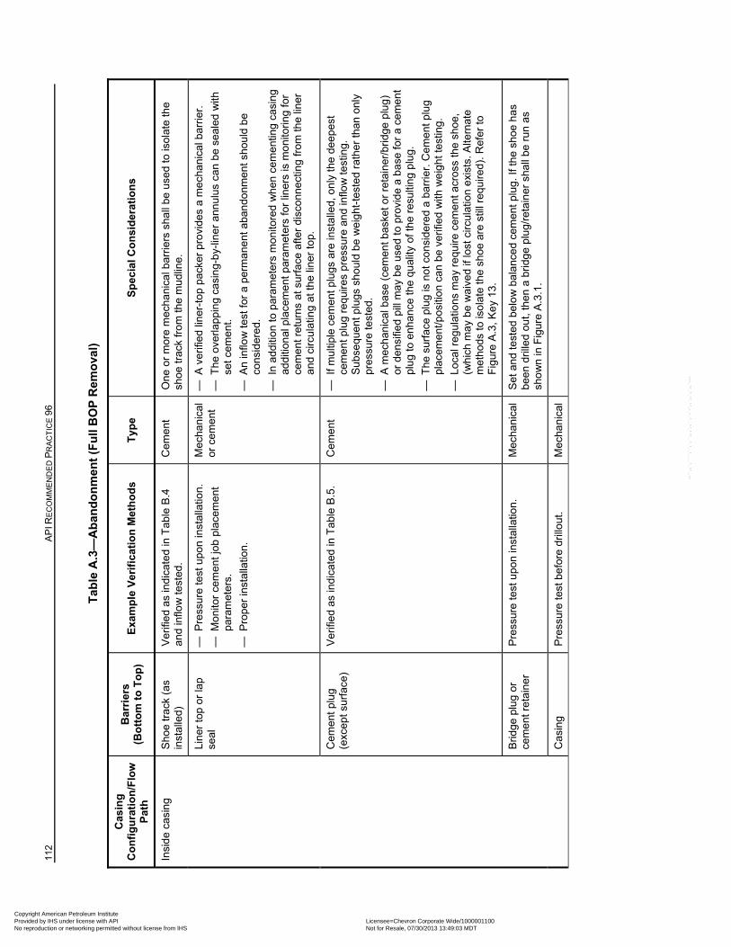
112
AP
I RE
CO
MM
EN
DE
D P
RA
CT
ICE
96
Tab
le A
.3—
Ab
and
on
men
t (F
ull
BO
P R
emo
val)
Cas
ing
C
on
fig
ura
tio
n/F
low
P
ath
Bar
rier
s
(Bo
tto
m t
o T
op
) E
xam
ple
Ver
ific
atio
n M
eth
od
s T
ype
S
pec
ial C
on
sid
erat
ion
s
Insi
de c
asin
g
Sho
e tr
ack
(as
inst
alle
d)
Ver
ifie
d as
ind
icat
ed in
Tab
le B
.4
and
inflo
w te
sted
. C
eme
nt
One
or
mor
e m
echa
nica
l bar
rier
s sh
all b
e us
ed to
isol
ate
the
shoe
trac
k fr
om
the
mud
line.
Lin
er to
p or
lap
se
al
— P
ress
ure
test
upo
n in
stal
latio
n.
— M
onito
r ce
men
t jo
b pl
acem
ent
pa
ram
eter
s.
— P
rope
r in
stal
latio
n.
Mec
hani
cal
or c
emen
t —
A v
erifi
ed li
ner-
top
pack
er p
rovi
des
a m
echa
nica
l bar
rier
.
— T
he o
verla
ppi
ng
casi
ng-
by-
liner
ann
ulus
can
be
seal
ed w
ith
set
cem
ent.
— A
n in
flow
test
for
a pe
rma
nent
aba
ndo
nmen
t sh
ould
be
cons
ider
ed.
— I
n ad
ditio
n to
par
amet
ers
mo
nito
red
wh
en c
em
entin
g ca
sin
g
add
ition
al p
lace
men
t par
amet
ers
for
liner
s is
mon
itori
ng fo
r ce
men
t ret
urns
at s
urfa
ce a
fter
disc
onne
ctin
g fr
om th
e lin
er
and
circ
ulat
ing
at th
e lin
er to
p.
Cem
ent
plu
g (e
xcep
t sur
face
) V
erifi
ed
as in
dic
ated
in T
able
B.5
. C
eme
nt
— I
f mul
tiple
cem
ent p
lugs
are
inst
alle
d, o
nly
the
de
epes
t ce
men
t plu
g re
quir
es p
ress
ure
and
inflo
w te
stin
g.
Sub
sequ
ent p
lugs
sho
uld
be w
eig
ht-t
este
d ra
ther
than
onl
y pr
essu
re te
sted
.
— A
mec
han
ical
bas
e (c
emen
t bas
ket o
r re
tain
er/b
ridg
e pl
ug
) or
den
sifie
d pi
ll m
ay
be
used
to
prov
ide
a b
ase
for
a ce
men
t pl
ug
to e
nhan
ce th
e qu
ality
of t
he r
esul
ting
plu
g.
— T
he s
urfa
ce p
lug
is n
ot c
ons
ider
ed
a ba
rrie
r. C
emen
t plu
g pl
acem
ent/p
ositi
on c
an b
e ve
rifie
d w
ith w
eig
ht
test
ing.
— L
oca
l reg
ula
tions
ma
y re
quire
cem
ent a
cros
s th
e sh
oe,
(wh
ich
ma
y be
wa
ive
d if
lost
cir
cula
tion
exi
sts.
Alte
rnat
e m
etho
ds to
iso
late
the
sho
e ar
e st
ill r
equi
red)
. R
efer
to
Fig
ure
A.3
, Ke
y 1
3.
Brid
ge
plu
g or
ce
men
t ret
aine
r P
ress
ure
test
upo
n in
stal
latio
n.
Mec
hani
cal
Set
and
test
ed b
elo
w b
ala
nce
d ce
men
t plu
g. If
the
shoe
ha
s be
en
drill
ed
out,
then
a b
ridg
e p
lug/
reta
iner
sha
ll be
run
as
sho
wn
in F
igur
e A
.3.1
.
Cas
ing
Pre
ssur
e te
st b
efor
e dr
illo
ut.
Mec
hani
cal
Copyright American Petroleum Institute Provided by IHS under license with API Licensee=Chevron Corporate Wide/1000001100
Not for Resale, 07/30/2013 13:49:03 MDTNo reproduction or networking permitted without license from IHS
--``,,`,````,``,`,``,,,`,,``,`-`-`,,`,,`,`,,`---
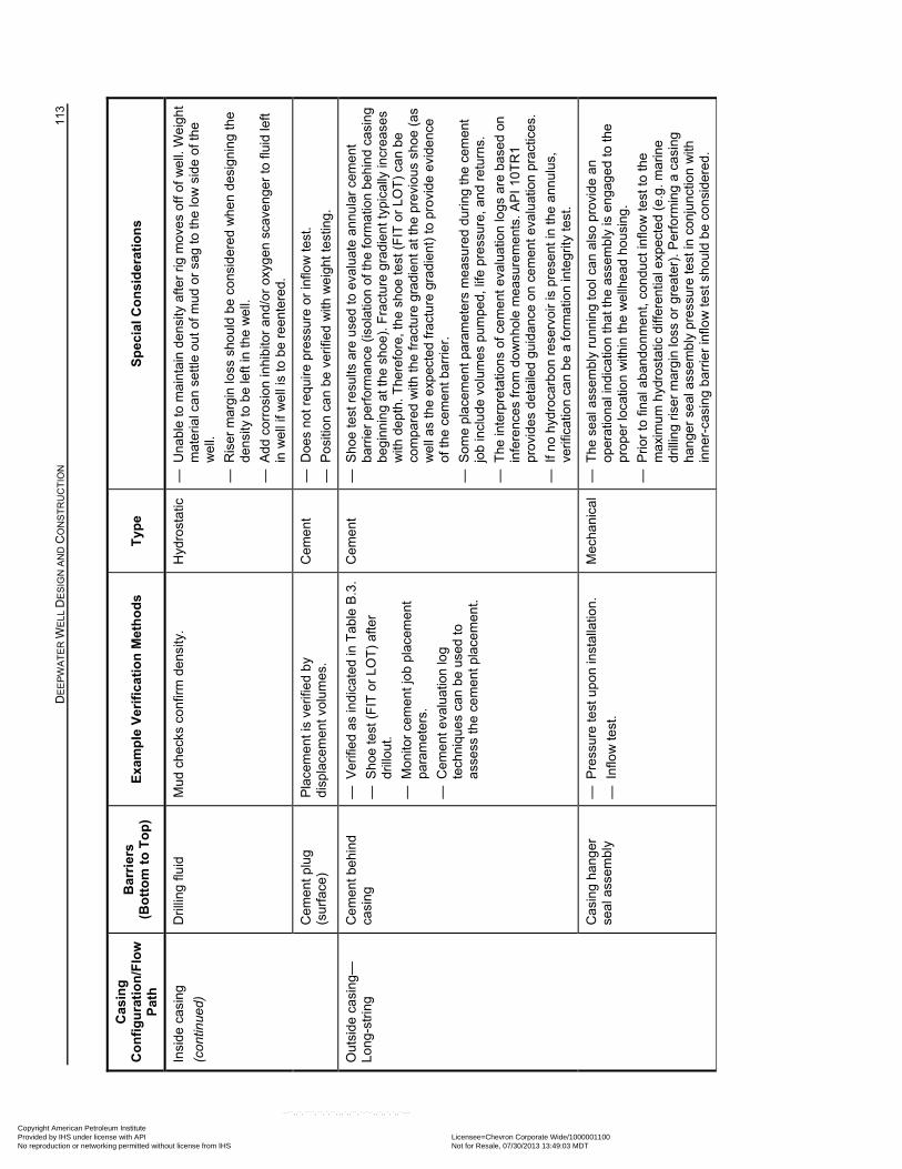
D
EE
PW
AT
ER
WE
LL D
ES
IGN
AN
D C
ON
ST
RU
CT
ION
11
3
Cas
ing
C
on
fig
ura
tio
n/F
low
P
ath
Bar
rier
s
(Bo
tto
m t
o T
op
) E
xam
ple
Ver
ific
atio
n M
eth
od
s T
ype
S
pec
ial C
on
sid
erat
ion
s
Insi
de c
asin
g
(con
tinue
d)
Dril
ling
fluid
M
ud c
heck
s co
nfirm
den
sity
. H
ydro
stat
ic
— U
nabl
e to
mai
nta
in d
ens
ity a
fter
rig m
oves
off
of
wel
l. W
eigh
t m
ater
ial c
an s
ettl
e ou
t of m
ud o
r sa
g to
the
low
sid
e of
the
we
ll.
— R
iser
mar
gin
loss
sho
uld
be c
onsi
dere
d w
he
n de
sign
ing
the
de
nsity
to b
e le
ft in
the
we
ll.
— A
dd c
orro
sion
inhi
bito
r an
d/or
oxy
ge
n sc
ave
nge
r to
flui
d le
ft in
wel
l if
we
ll is
to b
e re
ente
red.
Cem
ent
plu
g (s
urfa
ce)
Pla
cem
ent i
s ve
rifie
d b
y di
spla
cem
ent v
olum
es.
Cem
ent
—
Doe
s n
ot r
equ
ire
pres
sure
or
inflo
w te
st.
— P
ositi
on c
an b
e ve
rifie
d w
ith w
eig
ht te
stin
g.
Out
side
cas
ing
—Lo
ng-
strin
g
Cem
ent
beh
ind
ca
sing
—
Ver
ifie
d as
ind
icat
ed in
Tab
le B
.3.
— S
hoe
test
(F
IT o
r LO
T)
afte
r dr
illou
t.
— M
onito
r ce
men
t jo
b pl
acem
ent
pa
ram
eter
s.
— C
eme
nt e
valu
atio
n lo
g te
chni
ques
can
be
used
to
asse
ss th
e ce
men
t pla
cem
ent
.
Cem
ent
—
Sho
e te
st r
esu
lts a
re u
sed
to e
valu
ate
ann
ula
r ce
men
t ba
rrie
r pe
rfor
man
ce (
isol
atio
n of
the
form
atio
n be
hin
d ca
sin
g be
gin
nin
g at
the
shoe
). F
ract
ure
gra
die
nt t
ypic
ally
incr
ease
s w
ith d
ept
h. T
here
fore
, the
sho
e te
st (
FIT
or
LOT
) ca
n be
co
mpa
red
with
the
frac
ture
gra
die
nt a
t the
pre
viou
s sh
oe (
as
we
ll as
the
exp
ecte
d fr
actu
re g
rad
ient
) to
pro
vide
evi
denc
e of
the
cem
ent b
arrie
r.
— S
ome
plac
eme
nt p
aram
eter
s m
easu
red
dur
ing
the
cem
ent
jo
b in
clu
de v
olu
mes
pum
ped,
life
pre
ssur
e, a
nd r
etur
ns.
— T
he in
terp
reta
tions
of c
emen
t ev
alua
tion
logs
are
bas
ed
on
infe
renc
es fr
om
do
wn
hole
mea
sure
men
ts. A
PI 1
0TR
1 pr
ovid
es d
etai
led
guid
ance
on
cem
ent e
valu
atio
n pr
actic
es.
— I
f no
hyd
roca
rbon
res
ervo
ir is
pre
sent
in th
e an
nul
us,
verif
icat
ion
can
be
a fo
rmat
ion
inte
grity
tes
t.
Cas
ing
hang
er
seal
ass
embl
y —
Pre
ssur
e te
st u
pon
inst
alla
tion
.
— I
nflo
w t
est.
Mec
hani
cal
— T
he s
eal a
sse
mbl
y ru
nni
ng
tool
ca
n al
so p
rovi
de
an
oper
atio
nal
indi
catio
n th
at th
e as
sem
bly
is e
nga
ged
to th
e pr
oper
loca
tion
with
in th
e w
ellh
ead
hous
ing.
— P
rior
to fi
nal a
ban
don
me
nt, c
ondu
ct in
flow
test
to th
e m
axim
um h
ydro
stat
ic d
iffer
entia
l exp
ecte
d (e
.g. m
arin
e dr
illin
g ris
er m
arg
in lo
ss o
r gr
eat
er).
Per
form
ing
a ca
sing
ha
nge
r se
al a
ssem
bly
pres
sure
test
in c
onju
nct
ion
with
in
ner
-cas
ing
bar
rier
inflo
w te
st s
houl
d b
e co
nsi
dere
d.
Copyright American Petroleum Institute Provided by IHS under license with API Licensee=Chevron Corporate Wide/1000001100
Not for Resale, 07/30/2013 13:49:03 MDTNo reproduction or networking permitted without license from IHS
--``,,`,````,``,`,``,,,`,,``,`-`-`,,`,,`,`,,`---
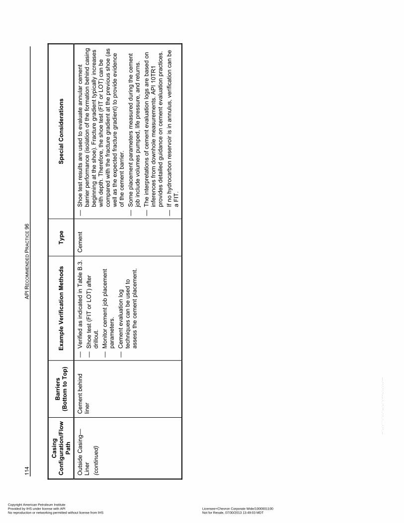
114
AP
I RE
CO
MM
EN
DE
D P
RA
CT
ICE
96
Cas
ing
C
on
fig
ura
tio
n/F
low
P
ath
Bar
rier
s
(Bo
tto
m t
o T
op
) E
xam
ple
Ver
ific
atio
n M
eth
od
s T
ype
S
pec
ial C
on
sid
erat
ion
s
Out
side
Cas
ing—
Lin
er
(con
tinue
d)
Cem
ent
beh
ind
lin
er
— V
erifi
ed
as in
dic
ated
in T
able
B.3
.
— S
hoe
test
(F
IT o
r LO
T)
afte
r dr
illou
t.
— M
onito
r ce
men
t jo
b pl
acem
ent
pa
ram
eter
s.
— C
eme
nt e
valu
atio
n lo
g te
chni
ques
can
be
used
to
asse
ss th
e ce
men
t pla
cem
ent
.
Cem
ent
—
Sho
e te
st r
esu
lts a
re u
sed
to e
valu
ate
ann
ula
r ce
men
t ba
rrie
r pe
rfor
man
ce (
isol
atio
n of
the
form
atio
n be
hin
d ca
sin
g be
gin
nin
g at
the
shoe
). F
ract
ure
gra
die
nt t
ypic
ally
incr
ease
s w
ith d
ept
h. T
here
fore
, the
sho
e te
st (
FIT
or
LOT
) ca
n be
co
mpa
red
with
the
frac
ture
gra
die
nt a
t the
pre
viou
s sh
oe (
as
we
ll as
the
exp
ecte
d fr
actu
re g
rad
ient
) to
pro
vide
evi
denc
e of
the
cem
ent b
arrie
r.
— S
ome
plac
eme
nt p
aram
eter
s m
easu
red
dur
ing
the
cem
ent
jo
b in
clu
de v
olu
mes
pum
ped,
life
pre
ssur
e, a
nd r
etur
ns.
— T
he in
terp
reta
tions
of c
emen
t ev
alua
tion
logs
are
bas
ed
on
infe
renc
es fr
om
do
wn
hole
mea
sure
men
ts. A
PI 1
0TR
1 pr
ovid
es d
etai
led
guid
ance
on
cem
ent e
valu
atio
n pr
actic
es.
— I
f no
hyd
roca
rbon
res
ervo
ir is
in a
nnul
us, v
erifi
catio
n ca
n b
e a
FIT
.
Copyright American Petroleum Institute Provided by IHS under license with API Licensee=Chevron Corporate Wide/1000001100
Not for Resale, 07/30/2013 13:49:03 MDTNo reproduction or networking permitted without license from IHS
--``,,`,````,``,`,``,,,`,,``,`-`-`,,`,,`,`,,`---
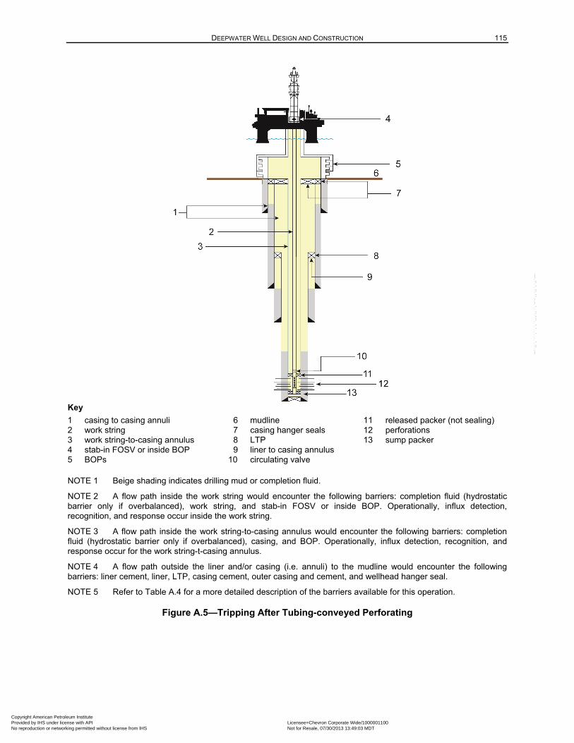
DEEPWATER WELL DESIGN AND CONSTRUCTION 115
Key
1 casing to casing annuli 6 mudline 11 released packer (not sealing) 2 work string 7 casing hanger seals 12 perforations 3 work string-to-casing annulus 8 LTP 13 sump packer 4 stab-in FOSV or inside BOP 9 liner to casing annulus 5 BOPs 10 circulating valve
NOTE 1 Beige shading indicates drilling mud or completion fluid.
NOTE 2 A flow path inside the work string would encounter the following barriers: completion fluid (hydrostatic barrier only if overbalanced), work string, and stab-in FOSV or inside BOP. Operationally, influx detection, recognition, and response occur inside the work string.
NOTE 3 A flow path inside the work string-to-casing annulus would encounter the following barriers: completion fluid (hydrostatic barrier only if overbalanced), casing, and BOP. Operationally, influx detection, recognition, and response occur for the work string-t-casing annulus.
NOTE 4 A flow path outside the liner and/or casing (i.e. annuli) to the mudline would encounter the following barriers: liner cement, liner, LTP, casing cement, outer casing and cement, and wellhead hanger seal.
NOTE 5 Refer to Table A.4 for a more detailed description of the barriers available for this operation.
Figure A.5—Tripping After Tubing-conveyed Perforating
Copyright American Petroleum Institute Provided by IHS under license with API Licensee=Chevron Corporate Wide/1000001100
Not for Resale, 07/30/2013 13:49:03 MDTNo reproduction or networking permitted without license from IHS
--``,,`,````,``,`,``,,,`,,``,`-`-`,,`,,`,`,,`---
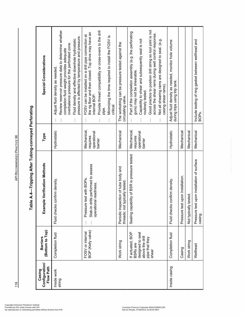
116
AP
I RE
CO
MM
EN
DE
D P
RA
CT
ICE
96
Tab
le A
.4—
Tri
pp
ing
Aft
er T
ub
ing
-co
nve
yed
Per
fora
tin
g
Cas
ing
C
on
fig
ura
tio
n/
Flo
w P
ath
Bar
rier
s
(Bo
tto
m t
o T
op
) E
xam
ple
Ver
ific
atio
n M
eth
od
s T
ype
S
pec
ial C
on
sid
erat
ion
s
Insi
de w
ork
st
ring
Com
plet
ion
fluid
F
luid
che
cks
conf
irm d
ensi
ty.
Hyd
rost
atic
—
A
djus
t flu
id d
ens
ity a
s ne
ede
d.
—
Rev
iew
res
ervo
ir pr
essu
re d
ata
to d
eter
min
e w
het
her
com
plet
ion
fluid
we
ight
pro
vid
es a
dequ
ate
over
bal
anc
e pr
essu
re fo
r th
e pe
rfor
ate
d zo
ne.
—
Flu
id d
ensi
ty a
nd e
ffect
ive
do
wn
hol
e h
ydro
stat
ic
pres
sure
is a
ffect
ed b
y te
mp
erat
ure
and
pre
ssur
e.
FO
SV
or
inte
rnal
B
OP
(K
elly
val
ve)
—
Pre
ssur
e te
st w
ith B
OP
s.
—
Sta
b-in
dri
lls p
erfo
rmed
to a
sses
s op
erat
ion
al r
ea
din
ess.
Mec
hani
cal,
requ
ires
oper
atio
nal
ba
rrie
r
—
FO
SV
can
be
inst
alle
d o
n a
dril
l pip
e co
nnec
tion
at
the
rig fl
oor
an
d th
en c
lose
d. T
op d
rive
ma
y ha
ve a
n in
tern
al B
OP
.
—
Pro
vid
e th
rea
d co
mpa
tibili
ty o
r cr
oss-
over
s to
the
drill
pi
pe.
—
Min
imiz
ing
the
time
requ
ired
to in
stal
l the
FO
SV
is
criti
cal.
Wor
k st
ring
Per
iodi
c in
spec
tion
of tu
be b
ody
and
thre
ads;
not
typ
ical
ly t
este
d.
Mec
hani
cal
The
wor
kstr
ing
can
be
pres
sure
test
ed a
gai
nst
the
circ
ulat
ing
valv
e.
If ac
tuat
ed,
BO
P
BS
Rs
are
desi
gne
d to
se
al
abov
e th
e dr
ill
pip
e th
at t
hey
shea
r
Sea
ling
capa
bilit
y of
BS
R is
pre
ssur
e te
sted
. M
echa
nica
l, re
quire
s op
erat
ion
al
barr
ier
—
Par
t of t
he c
ompl
etio
n as
sem
bly
(e.
g. th
e p
erfo
ratin
g gu
ns)
ma
y n
ot b
e sh
ear
abl
e.
—
Cap
abili
ty to
she
ar a
nd s
ubs
equ
ently
se
al is
not
ro
utin
ely
test
ed.
—
Goo
d pr
actic
e to
pos
ition
dril
l str
ing
so to
ol jo
int i
s no
t ac
ross
the
she
ar r
ams
duri
ng w
ell
cont
rol r
espo
nse.
—
Not
all
shea
rin
g ra
ms
are
desi
gned
to s
eal.
(e.g
. ca
sing
she
ar r
ams)
.
Insi
de c
asin
g
Com
plet
ion
fluid
F
luid
che
cks
conf
irm d
ens
ity.
Hyd
rost
atic
A
djus
t flu
id d
ensi
ty a
s ne
eded
, mon
itor
hole
vol
ume
duri
ng tr
ips
usin
g tr
ip ta
nk.
Cas
ing
P
ress
ure
test
upo
n in
stal
latio
n.
Mec
hani
cal
Wor
k st
ring
Not
typ
ical
ly t
este
d.
Mec
hani
cal
Wel
lhe
ad
Pre
ssur
e te
st u
pon
inst
alla
tion
of s
urfa
ce
casi
ng.
Mec
hani
cal
Incl
ude
test
ing
of r
ing
gask
et b
etw
een
we
llhea
d a
nd
BO
Ps.
Copyright American Petroleum Institute Provided by IHS under license with API Licensee=Chevron Corporate Wide/1000001100
Not for Resale, 07/30/2013 13:49:03 MDTNo reproduction or networking permitted without license from IHS
--``,,`,````,``,`,``,,,`,,``,`-`-`,,`,,`,`,,`---
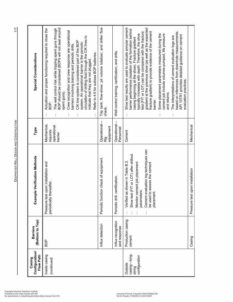
D
EE
PW
AT
ER
WE
LL D
ES
IGN
AN
D C
ON
ST
RU
CT
ION
11
7
Cas
ing
C
on
fig
ura
tio
n/
Flo
w P
ath
Bar
rier
s
(Bo
tto
m t
o T
op
) E
xam
ple
Ver
ific
atio
n M
eth
od
s T
ype
S
pec
ial C
on
sid
erat
ion
s
Insi
de c
asin
g
(con
tinue
d)
BO
P
Pre
ssur
e te
st u
pon
inst
alla
tion
and
pe
riodi
cally
the
reaf
ter.
M
echa
nica
l, re
quire
s op
erat
ion
al
barr
ier
—
Act
uatio
n a
nd p
rop
er fu
nctio
nin
g re
quir
ed to
clo
se th
e B
OP
.
—
The
wel
l con
tro
l ris
k w
hile
trip
pin
g sp
ent
gun
s th
roug
h B
OP
sho
uld
be c
onsi
der
ed (
BO
Ps
will
not
se
al a
roun
d sp
ent g
uns
).
—
Cre
w r
eco
gniti
on a
nd
cre
w r
esp
onse
are
op
erat
iona
l ba
rrie
rs in
volv
ing
trai
nin
g an
d p
erio
dic
drill
s.
—
C/K
line
sys
tem
is c
onsi
der
ed
part
of t
he B
OP
sy
stem
. An
oper
atio
nal b
arri
er
is th
e pe
riodi
c ci
rcul
atio
n of
dri
lling
flu
id th
rou
gh th
e C
/K li
ne
s to
in
dica
te th
at th
ey
are
not p
lug
ged.
—
Ref
er to
4.6
for
subs
ea B
OP
bat
terie
s.
Influ
x de
tect
ion
P
erio
dic
func
tion
chec
k of
eq
uipm
ent.
Ope
ratio
nal—
R
ig
equ
ipm
ent
Trip
tan
k; f
low
-sho
w;
pit
volu
me
tota
lizer
; a
nd d
rille
r flo
w
chec
k.
Influ
x re
cogn
ition
an
d re
spo
nse
P
erio
dic
drill
, cer
tific
atio
n.
Ope
ratio
nal—
Per
son
nel
Wel
l con
tro
l tra
inin
g, c
ertif
icat
ion,
and
dril
ls.
Out
side
ca
sing
—lo
ng-
strin
g co
nfig
urat
ion
Pro
duct
ion
casi
ng
cem
ent
—
Ver
ifie
d as
sho
wn
in T
able
B.3
.
—
Sho
e te
st (
FIT
or
LOT
) af
ter
drill
out
.
—
Mon
itor
cem
ent
job
plac
eme
nt
para
met
ers.
—
Cem
ent
eva
lua
tion
log
tech
niq
ues
can
be u
sed
to a
sses
s th
e ce
men
t pl
acem
ent.
Cem
ent
—
S
hoe
test
res
ults
are
use
d to
eva
luat
e a
nnu
lar
cem
ent
barr
ier
perf
orm
ance
(is
olat
ion
of th
e fo
rmat
ion
beh
ind
casi
ng
begi
nni
ng a
t the
sho
e).
Fra
ctur
e gr
adie
nt
typi
cally
incr
ea
ses
with
de
pth.
The
refo
re, t
he s
hoe
test
(F
IT o
r LO
T)
can
be c
ompa
red
with
the
frac
ture
gr
adie
nt a
t the
pre
viou
s sh
oe
(as
we
ll as
the
expe
cte
d fr
actu
re g
rad
ient
) to
pro
vide
evi
denc
e of
the
cem
ent
barr
ier.
—
Som
e pl
acem
ent
par
amet
ers
mea
sure
d d
urin
g th
e ce
men
t jo
b in
clud
e vo
lum
es p
umpe
d, li
fe p
ress
ure
and
retu
rns.
—
The
inte
rpre
tatio
ns o
f cem
ent
eval
uatio
n lo
gs a
re
base
d on
infe
renc
es fr
om d
ow
nh
ole
me
asur
emen
ts.
AP
I 10T
R1
prov
ides
det
aile
d gu
idan
ce o
n ce
men
t ev
alua
tion
prac
tices
.
C
asin
g
Pre
ssur
e te
st u
pon
inst
alla
tion
M
echa
nica
l
Copyright American Petroleum Institute Provided by IHS under license with API Licensee=Chevron Corporate Wide/1000001100
Not for Resale, 07/30/2013 13:49:03 MDTNo reproduction or networking permitted without license from IHS
--``,,`,````,``,`,``,,,`,,``,`-`-`,,`,,`,`,,`---
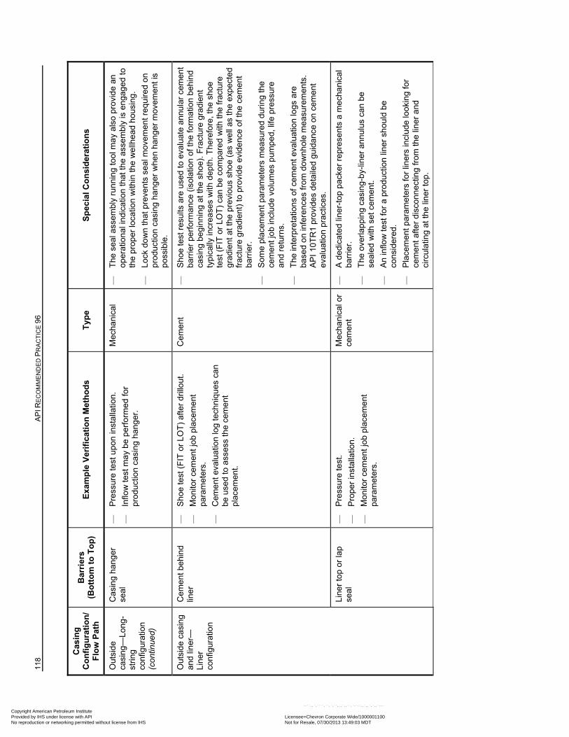
118
AP
I RE
CO
MM
EN
DE
D P
RA
CT
ICE
96
Cas
ing
C
on
fig
ura
tio
n/
Flo
w P
ath
Bar
rier
s
(Bo
tto
m t
o T
op
) E
xam
ple
Ver
ific
atio
n M
eth
od
s T
ype
S
pec
ial C
on
sid
erat
ion
s
Out
side
ca
sing
—Lo
ng-
strin
g co
nfig
urat
ion
(con
tinue
d)
Cas
ing
hang
er
seal
—
P
ress
ure
test
upo
n in
stal
latio
n.
—
Inflo
w t
est m
ay b
e pe
rfor
med
for
prod
uctio
n ca
sing
ha
nger
.
Mec
hani
cal
—
The
sea
l ass
em
bly
run
nin
g to
ol m
ay
als
o pr
ovid
e an
op
erat
ion
al in
dica
tion
that
the
asse
mb
ly is
en
gag
ed to
th
e pr
oper
loca
tion
with
in th
e w
ellh
ead
hou
sing
.
—
Lock
do
wn
that
pre
vent
s se
al m
ovem
ent
req
uire
d on
pr
oduc
tion
casi
ng h
ang
er w
hen
han
ger
mov
em
ent i
s po
ssib
le.
Out
side
cas
ing
an
d lin
er—
Lin
er
conf
igur
atio
n
Cem
ent
beh
ind
lin
er
—
Sho
e te
st (
FIT
or
LOT
) af
ter
drill
out
.
—
Mon
itor
cem
ent
job
plac
eme
nt
para
met
ers.
—
Cem
ent
eva
lua
tion
log
tech
niq
ues
can
be u
sed
to a
sses
s th
e ce
men
t pl
acem
ent.
Cem
ent
—
S
hoe
test
res
ults
are
use
d to
eva
luat
e a
nnu
lar
cem
ent
barr
ier
perf
orm
ance
(is
olat
ion
of th
e fo
rmat
ion
beh
ind
casi
ng
begi
nni
ng a
t the
sho
e).
Fra
ctur
e gr
adie
nt
typi
cally
incr
ea
ses
with
de
pth.
The
refo
re, t
he s
hoe
test
(F
IT o
r LO
T)
can
be c
ompa
red
with
the
frac
ture
gr
adie
nt a
t the
pre
viou
s sh
oe
(as
we
ll as
the
expe
cte
d fr
actu
re g
rad
ient
) to
pro
vide
evi
denc
e of
the
cem
ent
barr
ier.
—
Som
e pl
acem
ent
par
amet
ers
mea
sure
d d
urin
g th
e ce
men
t jo
b in
clud
e vo
lum
es p
umpe
d, li
fe p
ress
ure
and
retu
rns.
—
The
inte
rpre
tatio
ns o
f cem
ent
eval
uatio
n lo
gs a
re
base
d on
infe
renc
es fr
om d
ow
nh
ole
me
asur
emen
ts.
AP
I 10T
R1
prov
ides
det
aile
d gu
idan
ce o
n ce
men
t ev
alua
tion
prac
tices
.
Li
ner
top
or la
p
seal
—
P
ress
ure
test
.
—
Pro
per
inst
alla
tion.
—
Mon
itor
cem
ent
job
plac
eme
nt
para
met
ers.
Mec
hani
cal o
r ce
men
t —
A
ded
icat
ed li
ner
-top
pac
ker
repr
esen
ts a
mec
hani
cal
barr
ier.
—
The
ove
rlap
pin
g ca
sin
g-b
y-lin
er a
nnul
us c
an b
e se
aled
with
set
cem
ent.
—
An
inflo
w te
st fo
r a
prod
uctio
n li
ner
shou
ld b
e
cons
ider
ed.
—
Pla
cem
ent p
aram
eter
s fo
r lin
ers
incl
ude
loo
king
for
cem
ent a
fter
disc
onn
ectin
g fr
om th
e lin
er a
nd
circ
ulat
ing
at th
e lin
er to
p.
Copyright American Petroleum Institute Provided by IHS under license with API Licensee=Chevron Corporate Wide/1000001100
Not for Resale, 07/30/2013 13:49:03 MDTNo reproduction or networking permitted without license from IHS
--``,,`,````,``,`,``,,,`,,``,`-`-`,,`,,`,`,,`---
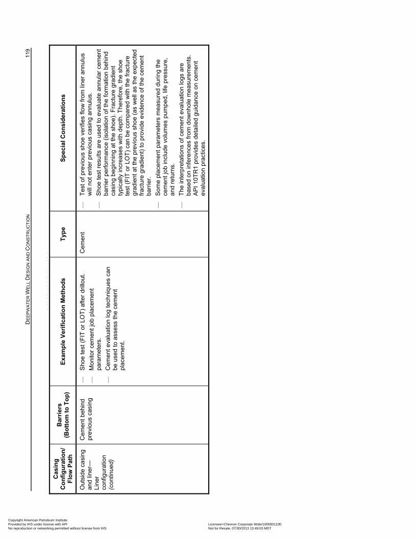
D
EE
PW
AT
ER
WE
LL D
ES
IGN
AN
D C
ON
ST
RU
CT
ION
11
9
Cas
ing
C
on
fig
ura
tio
n/
Flo
w P
ath
Bar
rier
s
(Bo
tto
m t
o T
op
) E
xam
ple
Ver
ific
atio
n M
eth
od
s T
ype
S
pec
ial C
on
sid
erat
ion
s
Out
side
cas
ing
an
d lin
er—
Lin
er
conf
igur
atio
n (c
ontin
ued)
Cem
ent
beh
ind
pr
evio
us c
asin
g —
S
hoe
test
(F
IT o
r LO
T)
afte
r dr
illo
ut.
—
Mon
itor
cem
ent
job
plac
eme
nt
para
met
ers.
—
Cem
ent
eva
lua
tion
log
tech
niq
ues
can
be u
sed
to a
sses
s th
e ce
men
t pl
acem
ent.
Cem
ent
—
T
est o
f pre
viou
s sh
oe v
erifi
es fl
ow
from
lin
er a
nnul
us
will
not
ent
er p
revi
ous
cas
ing
ann
ulus
.
—
Sho
e te
st r
esu
lts a
re u
sed
to e
valu
ate
ann
ula
r ce
men
t ba
rrie
r pe
rfor
man
ce (
isol
atio
n of
the
form
atio
n be
hin
d ca
sin
g be
gin
ning
at t
he s
hoe)
. F
ract
ure
grad
ient
ty
pica
lly in
cre
ase
s w
ith d
ept
h. T
here
fore
, the
sho
e te
st (
FIT
or
LOT
) ca
n be
com
pare
d w
ith th
e fr
actu
re
grad
ient
at t
he p
revi
ous
sho
e (a
s w
ell
as th
e ex
pect
ed
frac
ture
gra
die
nt)
to p
rovi
de e
vide
nce
of th
e ce
men
t ba
rrie
r.
—
Som
e pl
acem
ent
par
amet
ers
mea
sure
d d
urin
g th
e ce
men
t jo
b in
clud
e vo
lum
es p
umpe
d, li
fe p
ress
ure,
an
d re
turn
s.
—
The
inte
rpre
tatio
ns o
f cem
ent
eval
uatio
n lo
gs a
re
base
d on
infe
renc
es fr
om d
ow
nh
ole
me
asur
emen
ts.
AP
I 10T
R1
prov
ides
det
aile
d gu
idan
ce o
n ce
men
t ev
alua
tion
prac
tices
.
Copyright American Petroleum Institute Provided by IHS under license with API Licensee=Chevron Corporate Wide/1000001100
Not for Resale, 07/30/2013 13:49:03 MDTNo reproduction or networking permitted without license from IHS
--``,,`,````,``,`,``,,,`,,``,`-`-`,,`,,`,`,,`---
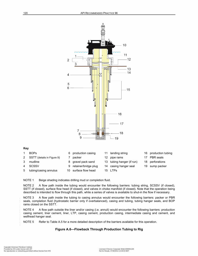
120 API RECOMMENDED PRACTICE 96
Key
1 BOPs 6 production casing 11 landing string 16 production tubing
2 SSTT (details in Figure 9) 7 packer 12 pipe rams 17 PBR seals
3 mudline 8 gravel pack sand 13 tubing hanger (if run) 18 perforations
4 SCSSV 9 retainer/bridge plug 14 casing hanger seal 19 sump packer
5 tubing/casing annulus 10 surface flow head 15 LTPs
NOTE 1 Beige shading indicates drilling mud or completion fluid.
NOTE 2 A flow path inside the tubing would encounter the following barriers: tubing string, SCSSV (if closed), SSTT (if closed), surface flow head (if closed), and valves in choke manifold (if closed). Note that the operation being described is intended to flow through this path, while a series of valves is available to shut-in the flow if necessary.
NOTE 3 A flow path inside the tubing to casing annulus would encounter the following barriers: packer or PBR seals, completion fluid (hydrostatic barrier only if overbalanced), casing and tubing, tubing hanger seals, and BOP rams closed on the SSTT.
NOTE 4 A flow path outside the liner and/or casing (i.e. annuli) would encounter the following barriers: production casing cement, liner cement, liner, LTP, casing cement, production casing, intermediate casing and cement, and wellhead hanger seal.
NOTE 5 Refer to Table A.5 for a more detailed description of the barriers available for this operation.
Figure A.6—Flowback Through Production Tubing to Rig
Copyright American Petroleum Institute Provided by IHS under license with API Licensee=Chevron Corporate Wide/1000001100
Not for Resale, 07/30/2013 13:49:03 MDTNo reproduction or networking permitted without license from IHS
--``,,`,````,``,`,``,,,`,,``,`-`-`,,`,,`,`,,`---
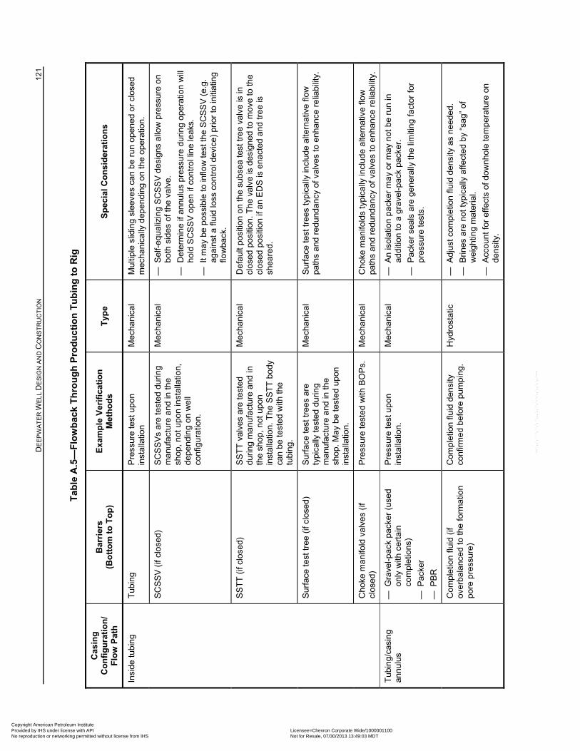
D
EE
PW
AT
ER
WE
LL D
ES
IGN
AN
D C
ON
ST
RU
CT
ION
12
1
Tab
le A
.5—
Flo
wb
ack
Th
rou
gh
Pro
du
ctio
n T
ub
ing
to
Rig
Cas
ing
C
on
fig
ura
tio
n/
Flo
w P
ath
Bar
rier
s
(Bo
tto
m t
o T
op
) E
xam
ple
Ver
ific
atio
n
Met
ho
ds
Typ
e
Sp
ecia
l C
on
sid
erat
ion
s
Insi
de tu
bin
g
Tub
ing
P
ress
ure
test
upo
n in
stal
latio
n
Mec
hani
cal
Mul
tiple
slid
ing
sle
eves
ca
n b
e ru
n op
ened
or
clos
ed
mec
hani
cally
dep
end
ing
on
the
oper
atio
n.
SC
SS
V (
if cl
osed
) S
CS
SV
s ar
e te
sted
dur
ing
man
ufac
ture
and
in th
e sh
op, n
ot u
pon
inst
alla
tion,
de
pen
din
g on
we
ll co
nfig
urat
ion.
Mec
hani
cal
— S
elf-
equa
lizin
g S
CS
SV
des
igns
allo
w p
ress
ure
on
both
sid
es o
f the
val
ve.
— D
eter
min
e if
annu
lus
pres
sure
dur
ing
oper
atio
n w
ill
hold
SC
SS
V o
pen
if co
ntro
l lin
e le
aks.
— I
t may
be
poss
ible
to in
flow
tes
t th
e S
CS
SV
(e.
g.
aga
inst
a fl
uid
loss
con
trol
dev
ice)
prio
r to
initi
atin
g flo
wba
ck.
SS
TT
(if
clos
ed)
SS
TT
val
ves
are
test
ed
duri
ng m
anuf
act
ure
and
in
the
shop
, not
upo
n in
stal
latio
n. T
he S
ST
T b
ody
can
be te
ste
d w
ith th
e tu
bin
g.
Mec
hani
cal
Def
ault
posi
tion
on th
e su
bse
a te
st tr
ee v
alve
is in
cl
ose
d po
sitio
n. T
he v
alve
is d
esig
ned
to m
ove
to th
e cl
ose
d po
sitio
n if
an
ED
S is
ena
cted
and
tre
e is
sh
eare
d.
Sur
face
test
tree
(if
clos
ed)
Sur
face
test
tree
s ar
e ty
pica
lly te
ste
d d
urin
g m
anuf
actu
re a
nd in
the
shop
. Ma
y be
tes
ted
upon
in
stal
latio
n.
Mec
hani
cal
Sur
face
test
tree
s ty
pic
ally
incl
ude
alte
rnat
ive
flo
w
path
s an
d re
du
nda
ncy
of v
alve
s to
enh
ance
rel
iabi
lity.
Cho
ke m
anifo
ld v
alve
s (if
cl
osed
) P
ress
ure
test
ed
with
BO
Ps.
M
echa
nica
l C
hoke
man
ifold
s ty
pic
ally
incl
ude
alte
rnat
ive
flo
w
path
s an
d re
du
nda
ncy
of v
alve
s to
enh
ance
rel
iabi
lity.
Tub
ing/
casi
ng
ann
ulus
— G
rave
l-pac
k pa
cker
(us
ed
only
with
cer
tain
co
mpl
etio
ns)
— P
acke
r
— P
BR
Pre
ssur
e te
st u
pon
inst
alla
tion.
M
echa
nica
l —
An
isol
atio
n pa
cker
ma
y or
ma
y no
t be
run
in
add
ition
to a
gra
vel-
pack
pac
ker.
— P
acke
r se
als
are
gen
eral
ly th
e lim
itin
g fa
ctor
for
pres
sure
test
s.
Com
plet
ion
fluid
(if
over
bal
anc
ed
to th
e fo
rmat
ion
po
re p
ress
ure)
Com
plet
ion
fluid
den
sity
co
nfirm
ed
befo
re p
ump
ing.
H
ydro
stat
ic
— A
djus
t com
ple
tion
fluid
de
nsity
as
need
ed.
— B
rines
are
not
typ
ical
ly a
ffect
ed
by
“sag
” of
w
eig
htin
g m
ate
rial.
— A
ccou
nt fo
r ef
fect
s of
do
wn
hole
tem
pera
ture
on
dens
ity.
Copyright American Petroleum Institute Provided by IHS under license with API Licensee=Chevron Corporate Wide/1000001100
Not for Resale, 07/30/2013 13:49:03 MDTNo reproduction or networking permitted without license from IHS
--``,,`,````,``,`,``,,,`,,``,`-`-`,,`,,`,`,,`---
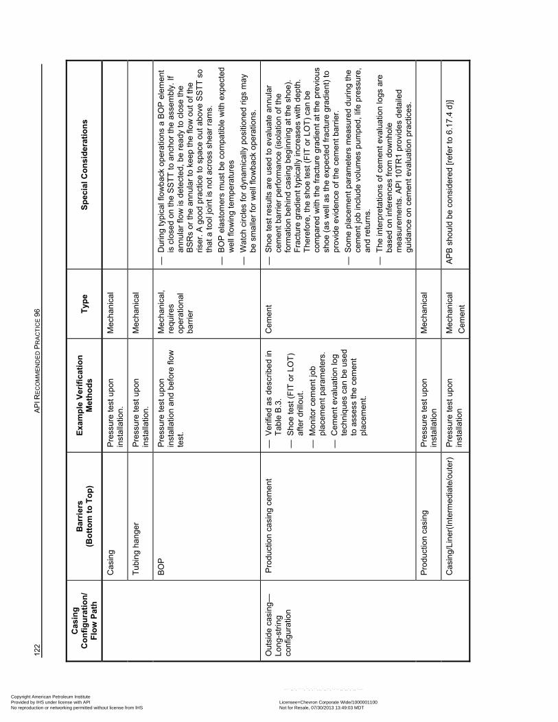
122
AP
I RE
CO
MM
EN
DE
D P
RA
CT
ICE
96
Cas
ing
C
on
fig
ura
tio
n/
Flo
w P
ath
Bar
rier
s
(Bo
tto
m t
o T
op
) E
xam
ple
Ver
ific
atio
n
Met
ho
ds
Typ
e
Sp
ecia
l C
on
sid
erat
ion
s
Cas
ing
P
ress
ure
test
upo
n in
stal
latio
n.
Mec
hani
cal
Tub
ing
hang
er
Pre
ssur
e te
st u
pon
inst
alla
tion.
M
echa
nica
l
BO
P
Pre
ssur
e te
st u
pon
inst
alla
tion
and
bef
ore
flow
te
st.
Mec
hani
cal,
requ
ires
oper
atio
nal
ba
rrie
r
— D
urin
g ty
pica
l flo
wb
ack
oper
atio
ns a
BO
P e
lem
ent
is c
lose
d on
the
SS
TT
to a
ncho
r th
e as
sem
bly.
If
ann
ular
flo
w is
det
ecte
d, b
e re
ady
to c
lose
the
BS
Rs
or th
e an
nula
r to
kee
p th
e flo
w o
ut o
f the
ris
er. A
goo
d p
ract
ice
to s
pace
out
ab
ove
SS
TT
so
that
a to
ol jo
int i
s no
t acr
oss
shea
r ra
ms.
— B
OP
ela
stom
ers
mus
t be
com
patib
le w
ith e
xpec
ted
we
ll flo
win
g te
mpe
ratu
res
— W
atch
circ
les
for
dyn
amic
ally
pos
ition
ed
rigs
ma
y be
sm
alle
r fo
r w
ell
flow
ba
ck o
pera
tions
.
Out
side
cas
ing
—Lo
ng-
strin
g co
nfig
urat
ion
Pro
duct
ion
casi
ng c
emen
t —
Ver
ifie
d as
des
crib
ed
in
Tab
le B
.3.
— S
hoe
test
(F
IT o
r LO
T)
afte
r dr
illou
t.
— M
onito
r ce
men
t jo
b pl
acem
ent p
aram
eter
s.
— C
eme
nt e
valu
atio
n lo
g te
chni
ques
can
be
used
to
ass
ess
the
cem
ent
plac
emen
t.
Cem
ent
—
Sho
e te
st r
esu
lts a
re u
sed
to e
valu
ate
ann
ula
r ce
men
t bar
rier
per
form
anc
e (i
sola
tion
of th
e fo
rmat
ion
beh
ind
casi
ng b
egin
ning
at t
he s
hoe
).
Fra
ctur
e gr
adie
nt ty
pica
lly in
crea
ses
with
de
pth
. T
here
fore
, the
sho
e te
st (
FIT
or
LOT
) ca
n be
co
mpa
red
with
the
frac
ture
gra
die
nt a
t the
pre
viou
s sh
oe (
as w
ell
as
the
expe
cte
d fr
actu
re g
rad
ient
) to
pr
ovid
e ev
ide
nce
of t
he c
eme
nt b
arrie
r.
— S
ome
plac
eme
nt p
aram
eter
s m
easu
red
dur
ing
the
cem
ent j
ob
incl
ude
volu
mes
pum
ped,
life
pre
ssur
e,
and
retu
rns.
— T
he in
terp
reta
tions
of c
emen
t ev
alua
tion
logs
are
ba
sed
on in
fere
nces
from
do
wn
hol
e m
easu
rem
ents
. A
PI 1
0TR
1 pr
ovid
es d
eta
iled
gu
idan
ce o
n ce
men
t eva
luat
ion
prac
tices
.
Pro
duct
ion
casi
ng
Pre
ssur
e te
st u
pon
inst
alla
tion
M
echa
nica
l
Cas
ing/
Line
r(In
term
edia
te/o
uter
) P
ress
ure
test
upo
n in
stal
latio
n
Mec
hani
cal
Cem
ent
AP
B s
houl
d be
con
sid
ered
[re
fer
to 6
.17.
4 d)
]
Copyright American Petroleum Institute Provided by IHS under license with API Licensee=Chevron Corporate Wide/1000001100
Not for Resale, 07/30/2013 13:49:03 MDTNo reproduction or networking permitted without license from IHS
--``,,`,````,``,`,``,,,`,,``,`-`-`,,`,,`,`,,`---
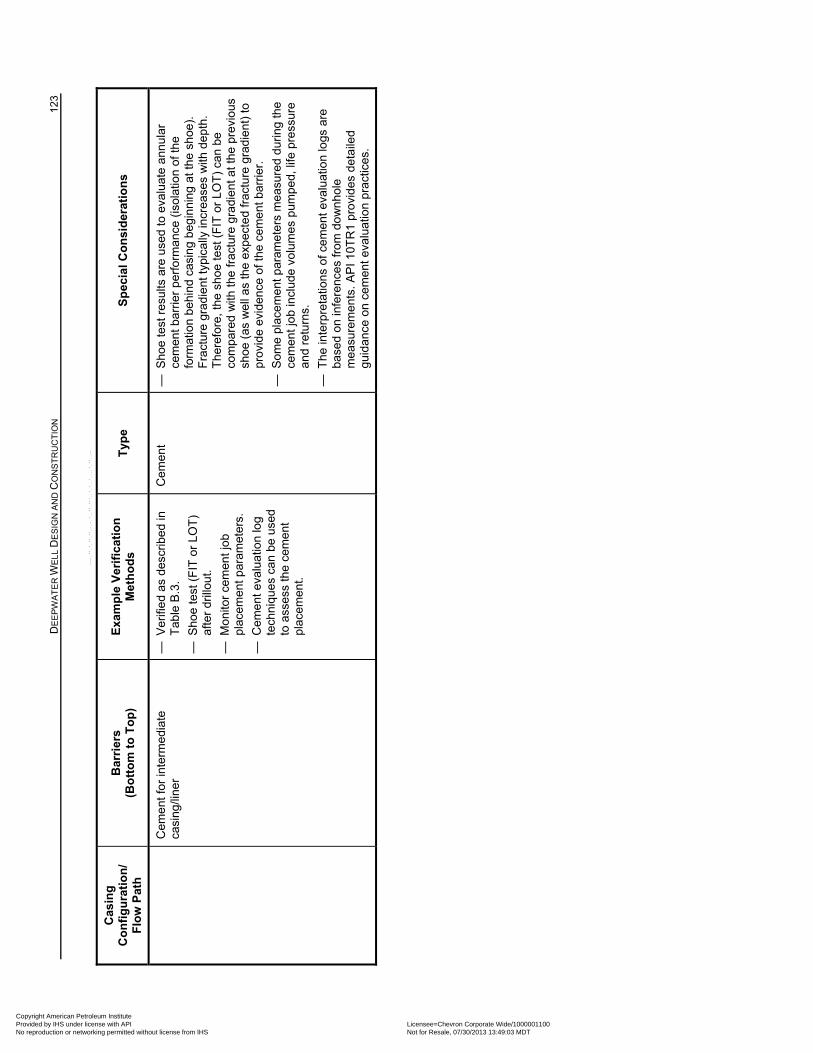
D
EE
PW
AT
ER
WE
LL D
ES
IGN
AN
D C
ON
ST
RU
CT
ION
12
3
Cas
ing
C
on
fig
ura
tio
n/
Flo
w P
ath
Bar
rier
s
(Bo
tto
m t
o T
op
) E
xam
ple
Ver
ific
atio
n
Met
ho
ds
Typ
e
Sp
ecia
l C
on
sid
erat
ion
s
Cem
ent
for
inte
rmed
iate
ca
sing
/line
r —
Ver
ifie
d as
des
crib
ed
in
Tab
le B
.3.
— S
hoe
test
(F
IT o
r LO
T)
afte
r dr
illou
t.
— M
onito
r ce
men
t jo
b pl
acem
ent p
aram
eter
s.
— C
eme
nt e
valu
atio
n lo
g te
chni
ques
can
be
used
to
ass
ess
the
cem
ent
plac
emen
t.
Cem
ent
—
Sho
e te
st r
esu
lts a
re u
sed
to e
valu
ate
ann
ula
r ce
men
t bar
rier
per
form
anc
e (i
sola
tion
of th
e fo
rmat
ion
beh
ind
casi
ng b
egin
ning
at t
he s
hoe
).
Fra
ctur
e gr
adie
nt ty
pica
lly in
crea
ses
with
de
pth
. T
here
fore
, the
sho
e te
st (
FIT
or
LOT
) ca
n be
co
mpa
red
with
the
frac
ture
gra
die
nt a
t the
pre
viou
s sh
oe (
as w
ell
as
the
expe
cte
d fr
actu
re g
rad
ient
) to
pr
ovid
e ev
ide
nce
of t
he c
eme
nt b
arrie
r.
— S
ome
plac
eme
nt p
aram
eter
s m
easu
red
dur
ing
the
cem
ent j
ob
incl
ude
volu
mes
pum
ped,
life
pre
ssur
e an
d re
turn
s.
— T
he in
terp
reta
tions
of c
emen
t ev
alua
tion
logs
are
ba
sed
on in
fere
nces
from
do
wn
hol
e m
easu
rem
ents
. A
PI 1
0TR
1 pr
ovid
es d
eta
iled
gu
idan
ce o
n ce
men
t eva
luat
ion
prac
tices
.
Copyright American Petroleum Institute Provided by IHS under license with API Licensee=Chevron Corporate Wide/1000001100
Not for Resale, 07/30/2013 13:49:03 MDTNo reproduction or networking permitted without license from IHS
--``,,`,````,``,`,``,,,`,,``,`-`-`,,`,,`,`,,`---
124
Annex B (informative)
Example Barrier Definitions
The tables included in this annex represent example descriptions of well barriers used during the drilling, completion, operation, and abandonment of DW wells. The tables list considerations associated with the selection and use of the well barriers. Well planners are encouraged to develop barrier tables specifically for their operations.
This annex is not intended to capture every possible type of barrier or to describe every consideration relevant to using the barriers that are included. The design and use considerations, suggested verification methods, and suggested approach to reestablishing the barrier do not preclude other alternatives. Annex A contains example schematics illustrating barriers that may be in place during specific well operations.
The following examples of well barriers described in this annex include:
— hydrostatic fluid (refer to Table B.1);
— casing (refer to Table B.2);
— cement behind casing or liner (refer to Table B.3);
— cemented shoe track (refer to Table B.4);
— cement plugs (refer to Table B.5);
— subsea wellhead (refer to Table B.6);
— subsea BOP system (refer to Table B.7);
— subsea tree (refer to Table B.8);
— production tubing string (refer to Table B.9);
— production packer (refer to Table B.10);
— surface-controlled subsurface safety valve (SCSSV) (refer to Table B.11);
— vertical tree tubing hanger plug (refer to Table B.12);
— horizontal tree crown plug (refer to Table B.13).
Copyright American Petroleum Institute Provided by IHS under license with API Licensee=Chevron Corporate Wide/1000001100
Not for Resale, 07/30/2013 13:49:03 MDTNo reproduction or networking permitted without license from IHS
--``,,`,````,``,`,``,,,`,,``,`-`-`,,`,,`,`,,`---
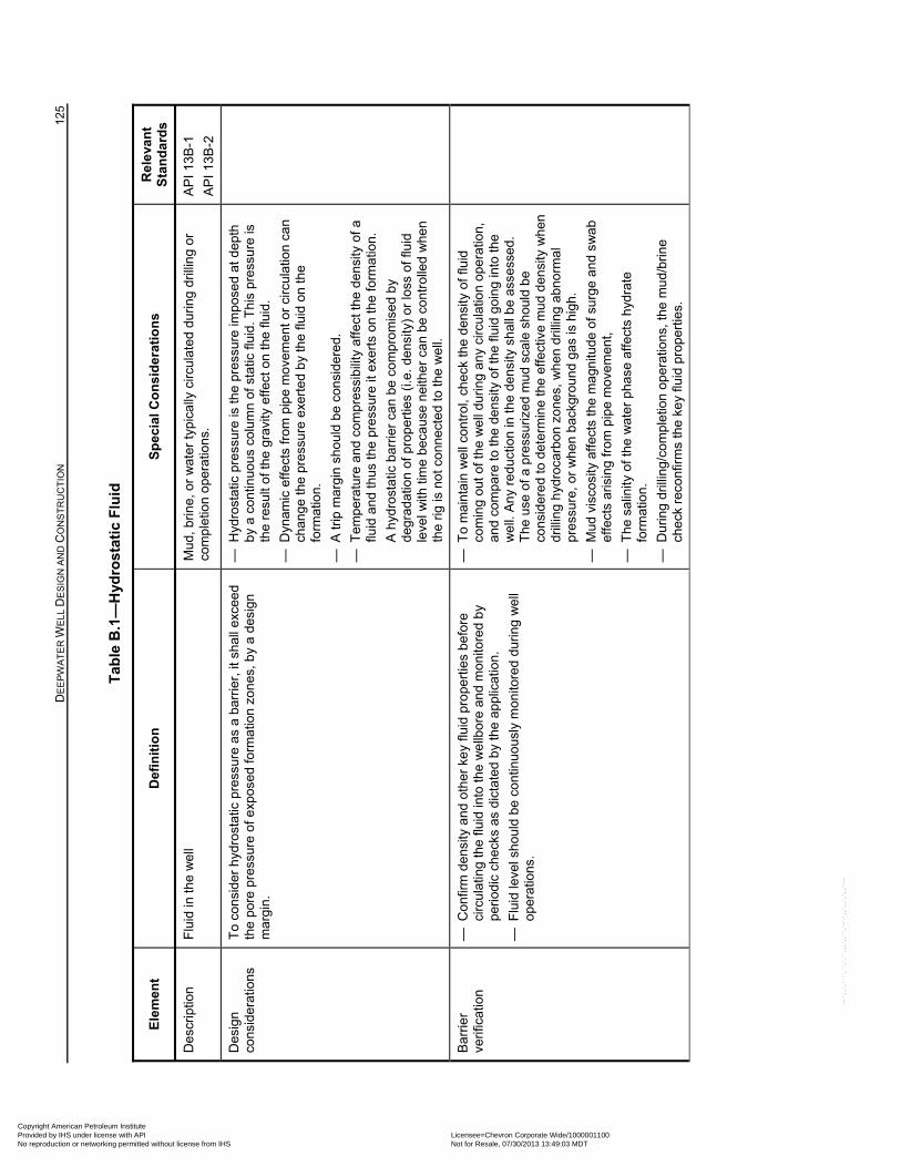
D
EE
PW
AT
ER
WE
LL D
ES
IGN
AN
D C
ON
ST
RU
CT
ION
12
5
Tab
le B
.1—
Hyd
rost
atic
Flu
id
Ele
men
t D
efin
itio
n
Sp
ecia
l Co
nsi
der
atio
ns
Rel
eva
nt
Sta
nd
ard
s
Des
crip
tion
F
luid
in th
e w
ell
Mud
, brin
e, o
r w
ater
typ
ica
lly c
ircul
ated
dur
ing
drill
ing
or
com
plet
ion
ope
ratio
ns.
AP
I 13B
-1
AP
I 13B
-2
Des
ign
cons
ider
atio
ns
To
cons
ider
hyd
rost
atic
pre
ssur
e as
a b
arri
er, i
t sha
ll e
xcee
d th
e po
re p
ress
ure
of e
xpos
ed fo
rmat
ion
zon
es, b
y a
des
ign
m
argi
n.
— H
ydro
stat
ic p
ress
ure
is th
e pr
essu
re im
pose
d at
dep
th
by
a co
ntin
uou
s co
lum
n of
sta
tic fl
uid.
Thi
s pr
essu
re is
th
e re
sult
of th
e gr
avity
effe
ct o
n th
e flu
id.
— D
ynam
ic e
ffect
s fr
om p
ipe
mo
vem
ent o
r ci
rcul
atio
n ca
n ch
ange
the
pre
ssur
e e
xert
ed
by
the
fluid
on
the
form
atio
n.
— A
trip
mar
gin
shou
ld b
e co
nsid
ere
d.
— T
empe
ratu
re a
nd c
ompr
essi
bili
ty a
ffect
the
den
sity
of a
flu
id a
nd th
us t
he p
ress
ure
it ex
erts
on
the
form
atio
n.
A h
ydro
stat
ic b
arrie
r ca
n be
com
prom
ised
by
degr
adat
ion
of p
rop
ertie
s (i.
e. d
ensi
ty)
or lo
ss o
f flu
id
leve
l with
tim
e be
caus
e n
eith
er
can
be c
ontr
olle
d w
he
n th
e rig
is n
ot c
onn
ecte
d to
the
we
ll.
Bar
rier
verif
icat
ion
— C
onfir
m d
ensi
ty a
nd o
ther
ke
y flu
id p
rope
rtie
s be
fore
ci
rcul
atin
g th
e flu
id in
to th
e w
ellb
ore
and
mon
itore
d b
y pe
riod
ic c
hec
ks a
s di
ctat
ed b
y th
e a
pplic
atio
n.
— F
luid
leve
l sh
oul
d b
e co
ntin
uous
ly m
onito
red
durin
g w
ell
oper
atio
ns.
— T
o m
aint
ain
we
ll co
ntro
l, ch
eck
the
dens
ity o
f flu
id
com
ing
out o
f the
we
ll du
ring
an
y ci
rcu
latio
n op
erat
ion,
an
d co
mpa
re to
the
dens
ity o
f the
flui
d g
oin
g in
to th
e w
ell.
An
y re
duct
ion
in th
e de
nsity
sh
all b
e as
sess
ed.
The
use
of a
pre
ssur
ized
mud
sca
le s
hou
ld b
e co
nsid
ere
d to
det
erm
ine
the
effe
ctiv
e m
ud d
ensi
ty w
hen
dr
illin
g h
ydro
carb
on z
one
s, w
hen
dril
ling
abn
orm
al
pres
sure
, or
whe
n b
ackg
roun
d ga
s is
hig
h.
— M
ud v
isco
sity
affe
cts
the
mag
nitu
de o
f sur
ge
and
swa
b ef
fect
s ar
isin
g fr
om p
ipe
mov
em
ent,
— T
he s
alin
ity o
f the
wat
er p
hase
affe
cts
hyd
rate
fo
rmat
ion.
— D
urin
g dr
illin
g/co
mpl
etio
n o
pera
tions
, the
mu
d/br
ine
chec
k re
conf
irm
s th
e ke
y flu
id p
rop
ertie
s.
Copyright American Petroleum Institute Provided by IHS under license with API Licensee=Chevron Corporate Wide/1000001100
Not for Resale, 07/30/2013 13:49:03 MDTNo reproduction or networking permitted without license from IHS
--``,,`,````,``,`,``,,,`,,``,`-`-`,,`,,`,`,,`---
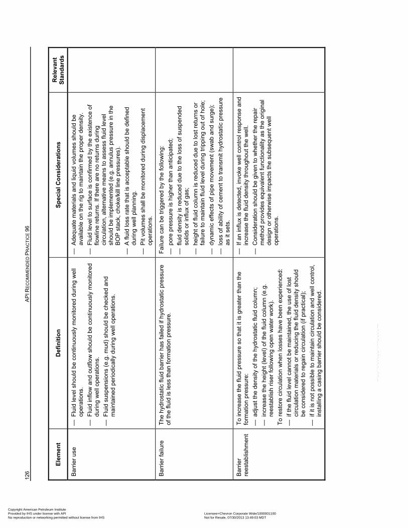
126
AP
I RE
CO
MM
EN
DE
D P
RA
CT
ICE
96
Ele
men
t D
efin
itio
n
Sp
ecia
l Co
nsi
der
atio
ns
Rel
eva
nt
Sta
nd
ard
s
Bar
rier
use
—
Flu
id le
vel s
ho
uld
be
cont
inuo
usly
mon
itore
d du
ring
we
ll op
erat
ions
.
— F
luid
inflo
w a
nd
outfl
ow
sh
ould
be
cont
inu
ousl
y m
oni
tore
d du
ring
we
ll o
pera
tions
.
— F
luid
sus
pens
ions
(e.
g. m
ud)
shou
ld b
e ch
ecke
d an
d m
aint
ain
ed
peri
odic
ally
dur
ing
we
ll o
pera
tion
s.
— A
deq
uate
mat
eria
ls a
nd li
quid
vol
umes
sho
uld
be
avai
lab
le o
n th
e rig
to m
aint
ain
the
prop
er d
ens
ity.
— F
luid
leve
l to
surf
ace
is c
onfir
med
by
the
exi
sten
ce o
f flo
wlin
e re
turn
s. If
ther
e ar
e no
ret
urns
dur
ing
circ
ulat
ion,
alte
rnat
ive
me
ans
to a
sses
s flu
id le
vel
shou
ld b
e im
plem
ente
d (e
.g. a
nnul
us p
ress
ure
in th
e B
OP
sta
ck, c
hoke
/kill
lin
e pr
ess
ures
).
— A
flui
d lo
ss r
ate
that
is a
ccep
tabl
e sh
oul
d b
e de
fined
du
ring
we
ll pl
ann
ing.
— P
it vo
lum
es s
hal
l be
mon
itore
d du
ring
dis
pla
cem
ent
oper
atio
ns.
Bar
rier
failu
re
The
hyd
rost
atic
flui
d ba
rrie
r h
as fa
iled
if h
ydro
stat
ic p
ress
ure
of th
e flu
id is
less
than
form
atio
n pr
essu
re.
Fai
lure
can
be
trig
gere
d b
y th
e fo
llow
ing:
— p
ore
pres
sure
is h
igh
er th
an a
ntic
ipat
ed;
— f
luid
den
sity
is r
educ
ed d
ue to
the
loss
of s
uspe
nde
d so
lids
or in
flux
of g
as;
— h
eigh
t of f
luid
col
umn
is r
educ
ed d
ue
to lo
st r
etur
ns o
r fa
ilure
to m
aint
ain
fluid
leve
l dur
ing
trip
ping
out
of h
ole;
— d
ynam
ic e
ffect
s of
pip
e m
ove
men
t (sw
ab
an
d su
rge)
;
— l
oss
of a
bilit
y o
f ce
men
t to
tran
smit
hyd
rost
atic
pre
ssur
e as
it s
ets.
Bar
rier
re
esta
blis
hmen
t T
o in
crea
se th
e flu
id p
ress
ure
so th
at it
is g
reat
er th
an th
e fo
rmat
ion
pres
sure
:
— a
djus
t the
den
sity
of t
he h
ydro
stat
ic fl
uid
colu
mn;
— i
ncre
ase
the
hei
ght
(le
vel)
of t
he fl
uid
colu
mn
(e.g
. re
esta
blis
h ris
er
follo
win
g op
en w
ate
r w
ork)
.
To
rest
ore
circ
ulat
ion
wh
en lo
sses
hav
e b
een
exp
erie
nced
:
— i
f the
flui
d le
vel c
anno
t be
mai
ntai
ned
, the
use
of l
ost
circ
ulat
ion
mat
eria
ls o
r re
duci
ng th
e flu
id d
ens
ity s
hou
ld
be c
onsi
der
ed t
o re
gain
circ
ulat
ion
(if p
ract
ical
);
— i
f it i
s no
t pos
sibl
e to
mai
ntai
n ci
rcul
atio
n a
nd w
ell
cont
rol,
inst
allin
g a
casi
ng b
arri
er s
hou
ld b
e co
nsid
ere
d.
— I
f an
influ
x is
det
ecte
d, in
voke
we
ll co
ntro
l re
spon
se a
nd
incr
eas
e th
e flu
id d
ens
ity th
rou
gho
ut th
e w
ell.
— C
onsi
dera
tion
shou
ld b
e gi
ven
to w
het
her
the
repa
ir m
etho
d pr
ovid
es e
quiv
alen
t fun
ctio
nalit
y as
the
orig
ina
l de
sign
or
oth
erw
ise
imp
acts
the
subs
eque
nt w
ell
oper
atio
ns.
Copyright American Petroleum Institute Provided by IHS under license with API Licensee=Chevron Corporate Wide/1000001100
Not for Resale, 07/30/2013 13:49:03 MDTNo reproduction or networking permitted without license from IHS
--``,,`,````,``,`,``,,,`,,``,`-`-`,,`,,`,`,,`---
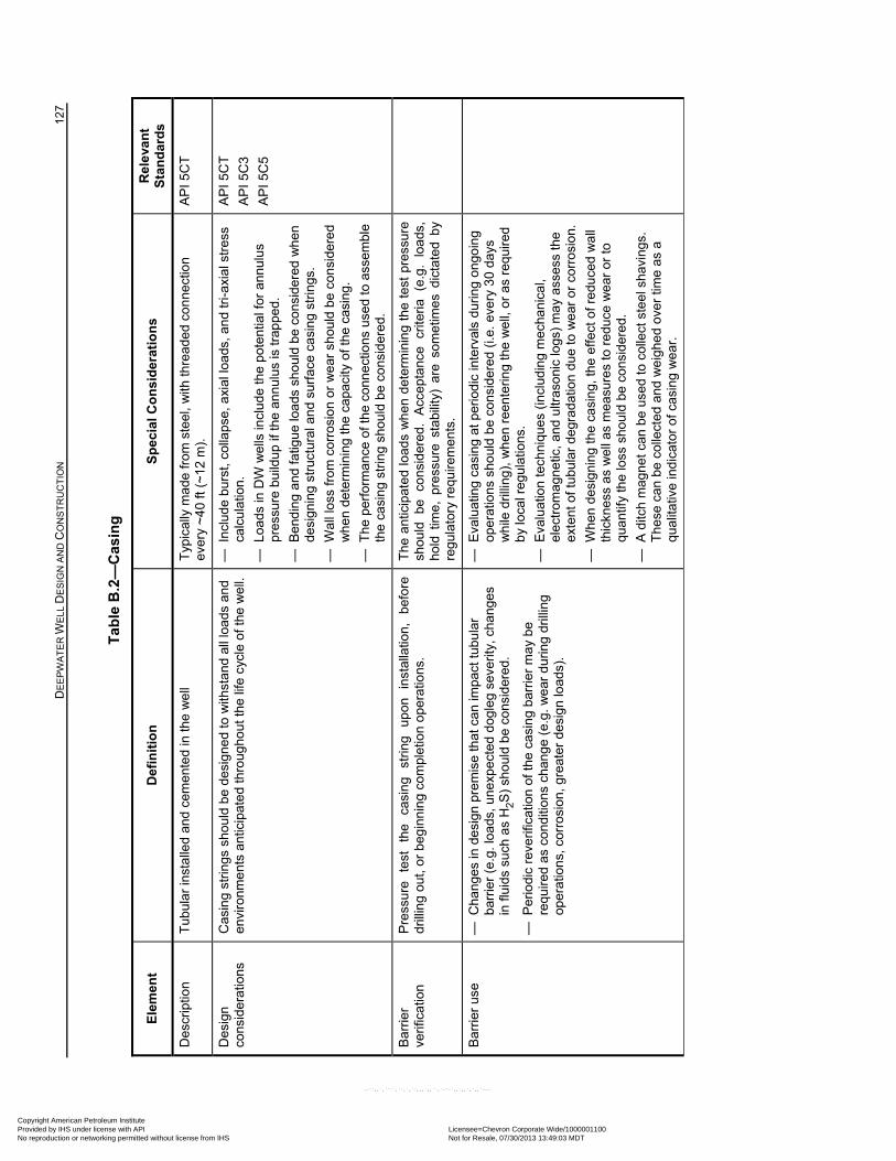
D
EE
PW
AT
ER
WE
LL D
ES
IGN
AN
D C
ON
ST
RU
CT
ION
12
7
Tab
le B
.2—
Cas
ing
Ele
men
t D
efin
itio
n
Sp
ecia
l Co
nsi
der
atio
ns
Rel
eva
nt
Sta
nd
ard
s
Des
crip
tion
T
ubul
ar in
stal
led
and
cem
ente
d in
the
we
ll T
ypic
ally
ma
de fr
om s
teel
, w
ith th
read
ed c
on
nect
ion
ever
y ~
40
ft (~
12 m
).
AP
I 5C
T
Des
ign
cons
ider
atio
ns
Cas
ing
strin
gs s
hou
ld b
e de
sign
ed
to w
ithst
and
all
loa
ds a
nd
envi
ronm
ent
s an
ticip
ate
d th
roug
hout
the
life
cycl
e of
the
we
ll.
— I
nclu
de
burs
t, co
llaps
e, a
xial
load
s, a
nd
tri-a
xial
str
ess
calc
ulat
ion.
— L
oads
in D
W w
ells
incl
ude
the
pot
entia
l for
ann
ulu
s pr
essu
re b
uild
up if
the
annu
lus
is tr
appe
d.
— B
end
ing
and
fatig
ue lo
ads
sho
uld
be
cons
ider
ed w
hen
de
sign
ing
stru
ctur
al a
nd
surf
ace
cas
ing
strin
gs.
— W
all l
oss
from
cor
rosi
on
or w
ear
sho
uld
be c
onsi
dere
d w
he
n de
term
inin
g th
e ca
paci
ty o
f the
cas
ing.
— T
he p
erfo
rman
ce o
f the
con
nec
tions
use
d to
ass
embl
e th
e ca
sin
g st
ring
shou
ld b
e co
nsid
ered
.
AP
I 5C
T
AP
I 5C
3
AP
I 5C
5
Bar
rier
verif
icat
ion
Pre
ssur
e te
st
the
casi
ng
strin
g up
on
inst
alla
tion,
be
fore
dr
illin
g ou
t, or
beg
inn
ing
com
plet
ion
ope
ratio
ns.
The
ant
icip
ate
d lo
ads
wh
en
dete
rmin
ing
the
test
pre
ssur
e sh
ould
be
co
nsid
ered
. A
ccep
tanc
e cr
iteri
a (e
.g.
loa
ds,
hold
tim
e, p
ress
ure
stab
ility
) ar
e so
met
ime
s di
ctat
ed b
y re
gula
tory
req
uire
men
ts.
Bar
rier
use
—
Cha
nges
in d
esi
gn p
rem
ise
that
can
impa
ct tu
bula
r ba
rrie
r (e
.g. l
oads
, une
xpec
ted
dog
leg
seve
rity,
cha
nges
in
flu
ids
such
as
H2S
) sh
ould
be
cons
ider
ed.
— P
erio
dic
reve
rific
atio
n of
the
casi
ng
barr
ier
ma
y be
re
quire
d as
co
nditi
ons
chan
ge
(e.g
. w
ear
du
ring
drill
ing
oper
atio
ns, c
orro
sio
n, g
reat
er d
esig
n lo
ads)
.
— E
valu
atin
g ca
sing
at p
erio
dic
inte
rval
s d
urin
g o
ngo
ing
oper
atio
ns s
houl
d b
e co
nsid
ered
(i.e
. eve
ry 3
0 da
ys
wh
ile d
rillin
g), w
he
n re
ente
ring
the
wel
l, or
as
requ
ired
b
y lo
cal r
egu
latio
ns.
— E
valu
atio
n te
chni
ques
(in
clud
ing
mec
han
ica
l, el
ectr
omag
net
ic, a
nd u
ltras
oni
c lo
gs)
ma
y as
sess
the
exte
nt o
f tub
ular
deg
rad
atio
n du
e to
we
ar o
r co
rros
ion.
— W
hen
desi
gni
ng
the
casi
ng,
the
effe
ct o
f red
uce
d w
all
thic
knes
s as
wel
l as
me
asur
es
to r
educ
e w
ear
or
to
qua
ntify
the
loss
sho
uld
be c
ons
ider
ed.
— A
ditc
h m
agn
et c
an b
e us
ed to
col
lect
ste
el s
havi
ngs.
T
hese
can
be
colle
cted
and
we
ighe
d ov
er ti
me
as a
qu
alit
ativ
e in
dic
ator
of c
asin
g w
ear
.
Copyright American Petroleum Institute Provided by IHS under license with API Licensee=Chevron Corporate Wide/1000001100
Not for Resale, 07/30/2013 13:49:03 MDTNo reproduction or networking permitted without license from IHS
--``,,`,````,``,`,``,,,`,,``,`-`-`,,`,,`,`,,`---
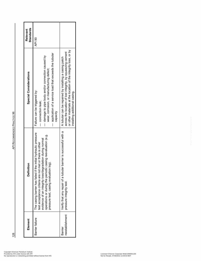
128
AP
I RE
CO
MM
EN
DE
D P
RA
CT
ICE
96
Ele
men
t D
efin
itio
n
Sp
ecia
l Co
nsi
der
atio
ns
Rel
eva
nt
Sta
nd
ard
s
Bar
rier
failu
re
The
cas
ing
barr
ier
has
faile
d if
the
initi
al h
ydra
ulic
pre
ssur
e te
st a
ccep
tanc
e cr
iteria
are
not
met
or
ther
e is
oth
er
evid
ence
of a
n in
tegr
ity lo
ss/d
egra
datio
n du
ring
nor
mal
op
erat
ions
or
dur
ing
the
peri
odi
c ca
sing
ree
valu
atio
n (e
.g.
pres
sure
test
, cas
ing
eval
uatio
n lo
g).
Fai
lure
can
be
trig
gere
d b
y:
— c
onn
ectio
n le
ak;
— d
ama
ge to
pip
e bo
dy
and
/or
conn
ectio
n ca
use
d b
y w
ear
, cor
rosi
on,
or
man
ufac
turin
g de
fect
;
— a
pplic
atio
n of
a s
ervi
ce lo
ad th
at e
xcee
ds th
e tu
bula
r ca
paci
ty
AP
I 90
Bar
rier
re
esta
blis
hmen
t V
erify
that
an
y re
pair
of a
tubu
lar
barr
ier
is s
ucc
essf
ul w
ith a
pr
essu
re in
tegr
ity t
est.
A tu
bula
r ca
n b
e re
paire
d b
y in
stal
ling
a ca
sing
pat
ch
acro
ss th
e lo
catio
n of
lost
inte
grity
, b
y sq
uee
zing
cem
ent
or o
ther
mat
eria
ls a
t the
loca
tion
of th
e in
tegr
ity lo
ss, o
r b
y in
stal
ling
addi
tiona
l cas
ing.
Copyright American Petroleum Institute Provided by IHS under license with API Licensee=Chevron Corporate Wide/1000001100
Not for Resale, 07/30/2013 13:49:03 MDTNo reproduction or networking permitted without license from IHS
--``,,`,````,``,`,``,,,`,,``,`-`-`,,`,,`,`,,`---
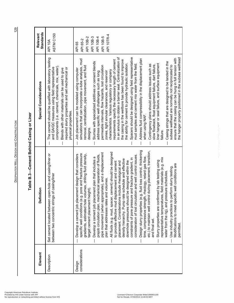
D
EE
PW
AT
ER
WE
LL D
ES
IGN
AN
D C
ON
ST
RU
CT
ION
12
9
Tab
le B
.3—
Cem
ent
Beh
ind
Cas
ing
or
Lin
er
Ele
men
t D
efin
itio
n
Sp
ecia
l Co
nsi
der
atio
ns
Rel
eva
nt
Sta
nd
ard
s
Des
crip
tion
S
et c
emen
t loc
ated
bet
we
en
ope
n-ho
le a
nd c
asin
g/lin
er o
r be
twe
en t
wo
conc
ent
ric s
trin
gs
of c
asin
g/lin
er
— T
he c
emen
t sho
uld
be q
ualif
ied
with
labo
rato
ry te
stin
g an
d Q
A/Q
C m
easu
res
usin
g fie
ld r
epre
sent
ativ
e co
mpo
nent
s (i.
e. c
emen
t, ch
em
ical
s, m
ix,
wa
ter)
.
— B
len
ds w
ith o
ther
mat
eria
ls c
an
be u
sed
to g
ive
requ
ired
slur
ry p
rop
ertie
s a
nd s
et m
echa
nic
al o
r ph
ysic
al p
rope
rtie
s.
AP
I 10A
AS
TM
C15
0
Des
ign
cons
ider
atio
ns
— D
evel
op a
cem
ent j
ob p
lace
men
t des
ign
that
con
sid
ers
spec
ific
we
ll co
nditi
ons
(e.g
. por
e an
d fr
actu
re p
ress
ure
grad
ient
s, e
stim
ated
ho
le v
olu
mes
, dril
ling
fluid
den
sity
, ta
rget
cem
ent
plac
emen
t hei
ght
).
— D
evel
op a
cem
ent j
ob p
lace
men
t pla
n th
at in
clud
es a
pr
ejob
circ
ula
tion
plan
, mec
han
ical
sep
arat
ion
of fl
uids
, pi
pe
mov
eme
nt
(whe
n ap
pro
pria
te),
and
a d
ispl
acem
ent
pla
n th
at a
ddre
sses
rat
es a
nd v
olum
es.
— A
ll flu
ids
(e.g
. mud
, spa
cer,
cem
ent)
sho
uld
be d
esig
ned
to p
rovi
de
effe
ctiv
e m
ud d
ispl
acem
ent
and
cem
ent
plac
emen
t. C
ons
ider
atio
ns in
clud
e rh
eolo
gica
l an
d de
nsity
hie
rarc
hy.
Pum
p ra
te s
ched
ule
and
effe
ctiv
e do
wn
hole
pre
ssur
es s
houl
d b
e de
sign
ed w
ithin
the
cons
trai
nts
of p
ore
pres
sure
and
frac
ture
gra
die
nt, i
n co
nsid
erat
ion
of
lost
circ
ulat
ion
and
we
ll co
ntro
l iss
ues
.
— D
esig
n sl
urry
pro
pert
ies
(e.g
. flu
id lo
ss c
ontr
ol,
thic
keni
ng
time,
com
pres
sive
str
engt
h, r
heo
log
y, r
etar
d ga
s flo
w,
etc.
) to
mai
ntai
n w
ell
cont
rol d
urin
g pl
acem
ent
, tra
nsiti
on,
and
final
set
.
— S
lurr
y pr
ope
rtie
s ar
e co
nfirm
ed b
y la
b te
stin
g us
ing
repr
esen
tativ
e te
mpe
ratu
res,
fiel
d m
ater
ials
(e.
g. m
ix
wat
er fr
om th
e rig
), a
nd p
ress
ure
sche
dule
s.
— U
se in
dust
ry p
ract
ices
to p
erfo
rm s
lurr
y te
stin
g.
Mod
ifica
tions
to
mee
t spe
cific
we
ll co
nditi
ons
are
perm
itted
.
— J
ob p
lace
me
nt c
an b
e m
ode
led
usin
g co
mp
uter
si
mul
atio
ns th
at
can
inco
rpor
ate
u-t
ube
ana
lysi
s, m
ud
rem
oval
, ce
ntra
lizat
ion,
pip
e m
ovem
ent
, and
flui
d de
sign
s.
— S
lurr
ies
with
sp
ecia
lize
d ad
ditiv
es o
r ce
men
t bl
end
s ad
dres
s sp
ecifi
c w
ell
chal
leng
es s
uch
as lo
ng
perm
eab
le in
terv
als,
flo
w h
azar
ds, l
ost c
ircul
atio
n zo
nes,
tigh
t an
nula
r cl
eara
nces
, and
res
ervo
ir ch
arac
teri
stic
s. V
ario
us r
egu
lato
ry o
r co
mpa
ny
requ
irem
ent
s sp
ecify
the
nec
ess
ary
len
gth
of c
emen
t in
an
ann
ulus
to
obta
in a
bar
rier
sea
l. C
ent
raliz
atio
n of
th
e ca
sin
g in
the
we
llbor
e ha
s be
en
foun
d to
impr
ove
the
abili
ty fo
r ce
men
t to
prov
ide
hyd
raul
ic is
olat
ion.
— S
pace
rs s
hou
ld b
e de
sig
ned
usin
g fie
ld r
epr
esen
tativ
e m
ud s
amp
les
and
cem
ent
mix
wat
er fr
om th
e fie
ld.
— A
ddre
ss fl
uid
com
pres
sibi
lity
in th
e di
spla
cem
ent p
lan
wh
en
usin
g N
AF
.
— C
ontin
genc
y pl
ans
sho
uld
add
ress
issu
es s
uch
as
slo
w fl
ow
back
, flo
at e
quip
men
t fa
ilure
, da
rt f
ailu
re,
liner
han
ger
or s
eal f
ailu
re, a
nd
surf
ace
equi
pmen
t fa
ilure
.
— C
asin
g st
rings
tha
t are
des
ign
ed to
be
land
ed
in th
e su
bse
a w
ellh
ead
are
nor
mal
ly n
ot r
ecip
roca
ted
to
ensu
re th
at th
e c
asin
g ca
n be
hun
g in
full
ten
sion
with
th
e ha
nge
r pr
ope
rly
pos
itio
ned
in th
e su
bsea
we
llhea
d
AP
I 65
AP
I 65
-2
AP
I 10
B-2
AP
I 10
B-3
AP
I 10
B-4
AP
I 10
B-5
AP
I 10T
R-4
Copyright American Petroleum Institute Provided by IHS under license with API Licensee=Chevron Corporate Wide/1000001100
Not for Resale, 07/30/2013 13:49:03 MDTNo reproduction or networking permitted without license from IHS
--``,,`,````,``,`,``,,,`,,``,`-`-`,,`,,`,`,,`---
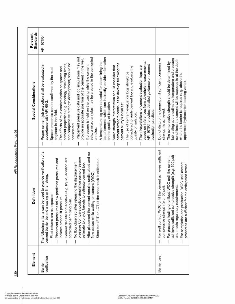
130
AP
I RE
CO
MM
EN
DE
D P
RA
CT
ICE
96
Ele
men
t D
efin
itio
n
Sp
ecia
l Co
nsi
der
atio
ns
Rel
eva
nt
Sta
nd
ard
s
Bar
rier
verif
icat
ion
The
follo
win
g cr
iteria
ca
n be
use
d to
pro
vide
ver
ifica
tion
of a
ce
men
t bar
rier
beh
ind
a ca
sin
g or
lin
er s
trin
g.
— F
luid
ret
urns
are
as
exp
ecte
d.
— P
lace
men
t pre
ssur
es fo
llow
pre
dict
ed
pres
sure
s an
d in
dica
te p
rope
r lif
t pre
ssur
e.
— C
eme
nt d
ensi
ty a
nd a
ddi
tive
(e.g
. liq
uid
) a
dditi
on a
re
cont
rolle
d p
er m
ixin
g pl
an.
— N
o flo
w o
bser
ved
afte
r re
leas
ing
the
disp
lace
men
t pr
essu
re C
ompa
re p
ostjo
b si
mul
atio
n pu
mp
pre
ssur
e es
timat
e to
pre
job
targ
ets
to e
stim
ate
cem
ent
top.
— A
fter
plac
eme
nt
the
cem
ent r
emai
ns u
ndis
turb
ed a
nd n
o flo
w o
ccur
s w
hile
wai
ting
on
cem
ent (
WO
C).
— S
hoe
test
(F
IT o
r LO
T)
if th
e sh
oe tr
ack
is d
rille
d o
ut.
— P
rope
r ce
men
t jo
b e
xecu
tion
shal
l be
eval
ua
ted
in
acco
rdan
ce w
ith A
PI 6
5-2.
— S
pace
r pr
oper
ties
can
be
conf
irmed
by
the
mud
en
gin
eer
in th
e fi
eld.
— T
he e
ffect
s of
mud
con
tam
inat
ion
on
spac
er
and
cem
ent p
rope
rtie
s (e
.g. r
heo
log
y, th
icke
ning
tim
es,
and
com
pres
sive
str
engt
h d
eve
lopm
ent)
sh
ould
be
cons
ider
ed.
—
Pla
cem
ent
pre
ssur
e da
ta a
nd jo
b si
mu
latio
ns
ma
y n
ot
prov
ide
an a
ccur
ate
posi
tion
of th
e ce
men
t in
the
wel
l.
— I
f pre
ssur
e is
hel
d o
n th
e ca
sing
wh
ile th
e ce
men
t se
ts, a
mic
ro-a
nnu
lus
ma
y b
e cr
eate
d in
the
cem
ente
d an
nul
us.
— A
tem
pera
ture
log
can
be u
sefu
l for
det
erm
inin
g th
e to
p of
cem
ent,
wh
ich
can
indi
rect
ly p
rovi
de in
form
atio
n on
the
qua
lity
of
isol
atio
n.
— S
onic
str
engt
h in
terp
reta
tion
shou
ld c
ons
ider
that
ce
men
t str
engt
h co
ntin
ues
to d
eve
lop
follo
win
g th
e ce
men
t slu
rry’
s in
itial
set
.
— T
he u
se o
f cem
ent e
valu
atio
n lo
gs s
hou
ld b
e co
nsid
ere
d to
ver
ify c
emen
t to
p an
d ev
alua
te th
e qu
alit
y of
isol
atio
n.
— T
he in
terp
reta
tions
of c
emen
t ev
alua
tion
logs
are
ba
sed
on in
fere
nces
from
do
wn
hol
e m
eas
urem
ents
. A
PI 1
0TR
1 pr
ovid
es d
etai
led
guid
ance
on
cem
ent
eval
uatio
n pr
actic
es.
AP
I 10T
R-1
Bar
rier
use
— F
or w
ell
cont
rol,
WO
C u
ntil
the
cem
ent a
chie
ves
suffi
cien
t co
mpr
essi
ve s
tren
gth
(e.g
. 50
psi).
— F
or p
ress
ure
test
ing
or d
rillo
ut, W
OC
unt
il th
e ce
men
t ac
hiev
es s
uffic
ient
com
pres
sive
str
engt
h (e
.g.
500
psi)
and
me
ets
reg
ulat
ory
requ
ire
men
ts.
— F
or c
ompl
etio
n a
nd p
rodu
ctio
n, W
OC
unt
il ce
men
t pr
oper
ties
are
suffi
cien
t for
the
antic
ipat
ed
stre
ss.
— D
o no
t dis
turb
the
cem
ent
unt
il su
ffici
ent c
ompr
essi
ve
stre
ngth
is a
chie
ved.
— T
he c
ompr
essi
ve s
tren
gth
shou
ld b
e d
eter
min
ed
by
lab
test
ing
at th
e es
timat
ed te
mpe
ratu
re a
nd
pres
sure
co
nditi
ons
the
cem
ent
will
be
expo
sed
to a
t the
de
pth
wh
ere
the
barr
ier
is r
equ
ired
(e.g
. abo
ve th
e up
per
mos
t hyd
roca
rbon
bea
ring
zon
e).
Copyright American Petroleum Institute Provided by IHS under license with API Licensee=Chevron Corporate Wide/1000001100
Not for Resale, 07/30/2013 13:49:03 MDTNo reproduction or networking permitted without license from IHS
--``,,`,````,``,`,``,,,`,,``,`-`-`,,`,,`,`,,`---
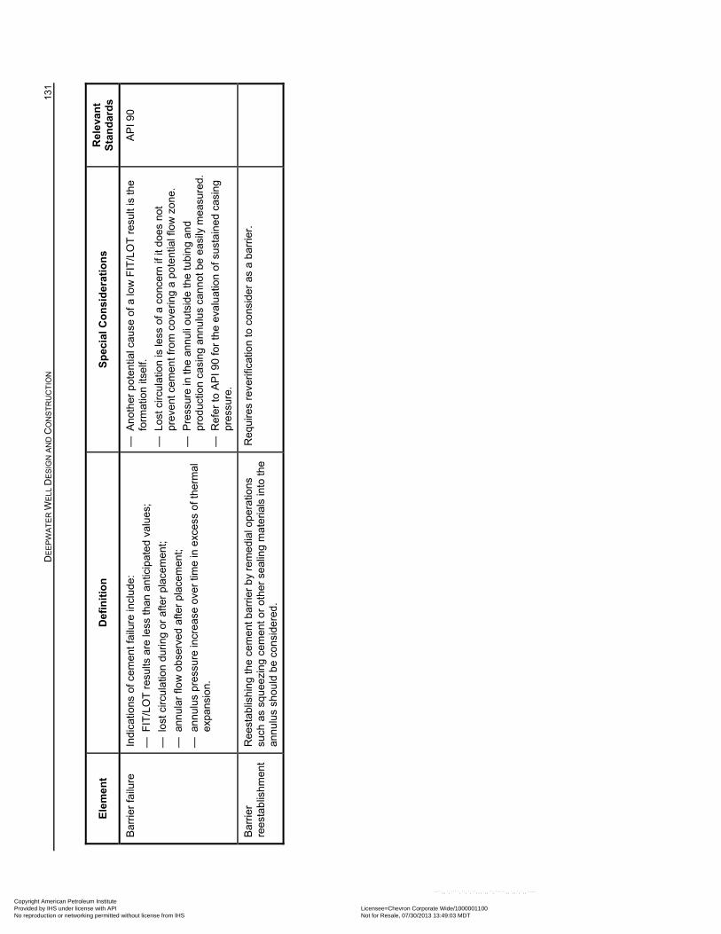
D
EE
PW
AT
ER
WE
LL D
ES
IGN
AN
D C
ON
ST
RU
CT
ION
13
1
Ele
men
t D
efin
itio
n
Sp
ecia
l Co
nsi
der
atio
ns
Rel
eva
nt
Sta
nd
ard
s
Bar
rier
failu
re
Indi
catio
ns o
f cem
ent f
ailu
re in
clu
de:
— F
IT/L
OT
res
ults
are
less
than
ant
icip
ate
d va
lues
;
— l
ost c
ircul
atio
n du
ring
or
afte
r pl
acem
ent;
— a
nnul
ar fl
ow
ob
serv
ed a
fter
plac
eme
nt;
— a
nnul
us p
ress
ure
incr
eas
e ov
er ti
me
in e
xce
ss o
f the
rmal
ex
pans
ion.
— A
noth
er p
oten
tial c
ause
of a
low
FIT
/LO
T r
esul
t is
the
form
atio
n its
elf.
— L
ost c
ircul
atio
n is
less
of a
con
cern
if it
doe
s no
t pr
eve
nt c
emen
t fr
om c
over
ing
a p
oten
tial f
low
zo
ne.
— P
ress
ure
in th
e a
nnu
li o
utsi
de t
he tu
bin
g an
d pr
oduc
tion
casi
ng a
nnu
lus
can
not b
e e
asily
mea
sure
d.
— R
efer
to A
PI 9
0 fo
r th
e ev
alu
atio
n of
sus
tain
ed c
asin
g pr
essu
re.
AP
I 90
Bar
rier
re
esta
blis
hmen
t R
eest
abl
ishi
ng
the
cem
ent b
arr
ier
by
rem
edi
al o
per
atio
ns
such
as
squ
eezi
ng c
emen
t or
othe
r se
alin
g m
ater
ials
into
the
ann
ulus
sho
uld
be
cons
ider
ed.
Req
uire
s re
veri
ficat
ion
to c
ons
ider
as
a b
arrie
r.
Copyright American Petroleum Institute Provided by IHS under license with API Licensee=Chevron Corporate Wide/1000001100
Not for Resale, 07/30/2013 13:49:03 MDTNo reproduction or networking permitted without license from IHS
--``,,`,````,``,`,``,,,`,,``,`-`-`,,`,,`,`,,`---
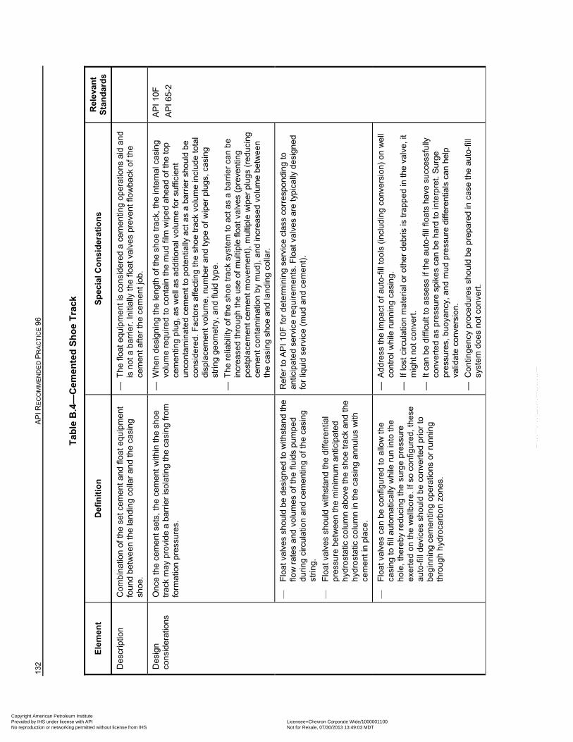
132
AP
I RE
CO
MM
EN
DE
D P
RA
CT
ICE
96
Tab
le B
.4—
Cem
ente
d S
ho
e T
rack
Ele
men
t D
efin
itio
n
Sp
ecia
l Co
nsi
der
atio
ns
Rel
eva
nt
Sta
nd
ard
s
Des
crip
tion
C
ombi
natio
n of
the
set c
emen
t an
d flo
at e
qui
pmen
t fo
und
bet
we
en th
e la
ndin
g co
llar
and
the
casi
ng
shoe
.
— T
he fl
oat e
quip
men
t is
cons
ider
ed a
cem
entin
g op
erat
ions
aid
and
is
not
a b
arri
er. I
nitia
lly th
e flo
at v
alve
s pr
eve
nt fl
ow
back
of t
he
cem
ent a
fter
the
cem
ent j
ob.
Des
ign
cons
ider
atio
ns
Onc
e th
e ce
me
nt s
ets,
the
cem
ent
with
in th
e s
hoe
trac
k m
ay
prov
ide
a ba
rrie
r is
ola
ting
the
casi
ng
from
fo
rmat
ion
pres
sure
s.
— W
hen
desi
gni
ng
the
len
gth
of th
e sh
oe tr
ack,
the
inte
rna
l ca
sing
vo
lum
e re
quire
d to
con
tain
the
mud
film
wip
ed a
hea
d of
the
top
cem
entin
g pl
ug, a
s w
ell
as a
ddi
tiona
l vo
lum
e fo
r su
ffici
ent
unco
ntam
inat
ed
cem
ent t
o po
tent
ially
act
as
a ba
rrie
r sh
ould
be
cons
ider
ed.
Fac
tors
affe
ctin
g th
e sh
oe
trac
k vo
lum
e in
clud
e to
tal
disp
lace
men
t vol
ume,
num
ber
and
type
of
wip
er p
lugs
, cas
ing
strin
g ge
omet
ry, a
nd
fluid
typ
e.
— T
he r
elia
bilit
y o
f th
e sh
oe tr
ack
syst
em to
act
as
a ba
rrie
r ca
n be
in
cre
ased
thro
ugh
the
use
of m
ultip
le fl
oat v
alve
s (p
reve
ntin
g po
stpl
acem
ent
cem
ent m
ove
men
t), m
ultip
le w
iper
plu
gs (
redu
cing
ce
men
t con
tam
inat
ion
by
mu
d), a
nd in
crea
sed
volu
me
bet
we
en
the
casi
ng
sho
e an
d la
ndi
ng
colla
r.
AP
I 10
F
AP
I 65-
2
—
Flo
at v
alve
s sh
ould
be
des
ign
ed to
with
sta
nd th
e flo
w r
ates
an
d vo
lum
es o
f the
flui
ds p
umpe
d du
ring
circ
ula
tion
and
cem
ent
ing
of th
e ca
sin
g st
ring.
—
Flo
at v
alve
s sh
ould
with
sta
nd t
he d
iffer
entia
l pr
essu
re b
etw
een
the
min
imum
ant
icip
ate
d h
ydro
stat
ic c
olu
mn
abov
e th
e s
hoe
trac
k an
d th
e h
ydro
stat
ic c
olu
mn
in th
e ca
sing
an
nulu
s w
ith
cem
ent i
n p
lace
.
Ref
er to
AP
I 10F
for
dete
rmin
ing
serv
ice
clas
s co
rres
pond
ing
to
antic
ipat
ed
serv
ice
req
uire
me
nts.
Flo
at v
alve
s ar
e ty
pic
ally
des
igne
d fo
r liq
uid
ser
vice
(m
ud a
nd
cem
ent)
.
—
Flo
at v
alve
s ca
n be
con
figur
ed
to a
llow
the
casi
ng
to fi
ll au
tom
atic
ally
wh
ile r
un in
to th
e ho
le, t
here
by
redu
cing
the
surg
e pr
essu
re
exer
ted
on
the
we
llbor
e. If
so
conf
igur
ed, t
hese
au
to-f
ill d
evic
es
shou
ld b
e co
nver
ted
prio
r to
be
gin
nin
g ce
men
ting
oper
atio
ns o
r ru
nnin
g th
roug
h h
ydro
carb
on
zon
es.
— A
ddre
ss th
e im
pact
of a
uto-
fill t
ools
(in
clud
ing
con
vers
ion)
on
we
ll co
ntro
l wh
ile r
unn
ing
casi
ng.
— I
f los
t circ
ulat
ion
mat
eria
l or
othe
r de
bris
is tr
app
ed in
the
valv
e, it
m
ight
not
con
vert
.
— I
t can
be
diffi
cult
to a
sses
s if
the
auto
-fill
flo
ats
have
suc
cess
fully
co
nver
ted
as p
ress
ure
spik
es c
an b
e h
ard
to in
terp
ret.
Sur
ge
pres
sure
s, b
uoya
ncy,
and
mu
d pr
essu
re d
iffer
entia
ls c
an h
elp
valid
ate
conv
ersi
on.
— C
ontin
genc
y pr
oced
ures
sh
ould
be
pre
pare
d in
cas
e th
e a
uto-
fill
syst
em d
oes
not
con
vert
.
Copyright American Petroleum Institute Provided by IHS under license with API Licensee=Chevron Corporate Wide/1000001100
Not for Resale, 07/30/2013 13:49:03 MDTNo reproduction or networking permitted without license from IHS
--``,,`,````,``,`,``,,,`,,``,`-`-`,,`,,`,`,,`---
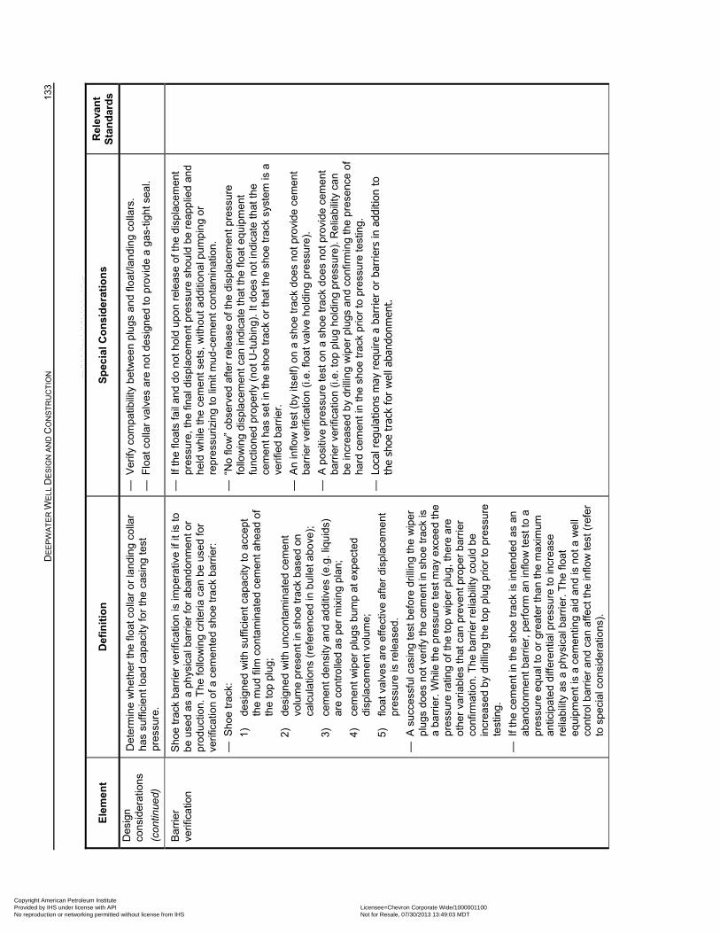
D
EE
PW
AT
ER
WE
LL D
ES
IGN
AN
D C
ON
ST
RU
CT
ION
13
3
Ele
men
t D
efin
itio
n
Sp
ecia
l Co
nsi
der
atio
ns
Rel
eva
nt
Sta
nd
ard
s
Des
ign
cons
ider
atio
ns
(con
tinue
d)
Det
erm
ine
wh
eth
er th
e flo
at c
olla
r or
lan
din
g c
olla
r ha
s su
ffici
ent
load
ca
paci
ty fo
r th
e ca
sing
test
pr
essu
re.
— V
erify
com
patib
ility
bet
wee
n pl
ugs
an
d flo
at/la
ndi
ng
colla
rs.
— F
loat
col
lar
valv
es a
re n
ot d
esi
gned
to p
rovi
de a
gas
-tig
ht s
eal.
Bar
rier
verif
icat
ion
S
hoe
trac
k b
arrie
r ve
rific
atio
n is
impe
rativ
e if
it is
to
be u
sed
as a
ph
ysic
al b
arri
er fo
r ab
and
onm
ent
or
prod
uctio
n. T
he fo
llow
ing
crite
ria c
an
be u
sed
for
verif
icat
ion
of a
cem
ente
d sh
oe
trac
k ba
rrie
r:
— S
hoe
trac
k:
1)
desi
gne
d w
ith s
uffic
ient
cap
aci
ty to
acc
ept
th
e m
ud fi
lm c
ont
amin
ated
ce
men
t ahe
ad o
f th
e to
p pl
ug;
2)
desi
gne
d w
ith u
nco
ntam
inat
ed
cem
ent
volu
me
pres
en
t in
sho
e tr
ack
base
d on
ca
lcul
atio
ns (
refe
renc
ed
in b
ulle
t abo
ve);
3)
cem
ent d
ens
ity a
nd a
ddi
tives
(e.
g. li
quid
s)
are
cont
rolle
d as
per
mix
ing
pla
n;
4)
cem
ent
wip
er p
lugs
bum
p at
exp
ecte
d di
spla
cem
ent v
olum
e;
5)
float
val
ves
are
effe
ctiv
e af
ter
disp
lace
men
t pr
essu
re is
rel
ease
d.
— A
suc
cess
ful c
asin
g te
st b
efo
re d
rillin
g th
e w
iper
pl
ugs
do
es n
ot v
erify
the
cem
ent
in s
hoe
trac
k is
a
barr
ier.
Whi
le th
e pr
essu
re t
est m
ay
exc
eed
the
pres
sure
rat
ing
of t
he to
p w
ipe
r pl
ug, t
here
are
ot
her
vari
able
s th
at c
an p
reve
nt p
rope
r b
arri
er
conf
irmat
ion.
The
bar
rier
rel
iabi
lity
coul
d b
e in
cre
ased
by
dril
ling
the
top
plug
prio
r to
pre
ssur
e te
stin
g.
— I
f the
cem
ent i
n th
e sh
oe
trac
k is
inte
nded
as
an
aba
ndon
me
nt b
arrie
r, p
erfo
rm a
n in
flow
test
to a
pr
essu
re e
qua
l to
or g
reat
er th
an th
e m
axi
mum
an
ticip
ate
d di
ffere
ntia
l pre
ssu
re to
incr
ease
re
liabi
lity
as a
ph
ysic
al b
arri
er. T
he fl
oat
equ
ipm
ent
is a
cem
entin
g ai
d an
d is
not
a w
ell
cont
rol b
arrie
r an
d ca
n af
fect
the
inflo
w te
st (
refe
r to
spe
cia
l con
side
ratio
ns).
— I
f the
floa
ts fa
il an
d d
o no
t ho
ld u
pon
rele
ase
of t
he d
ispl
ace
men
t pr
essu
re, t
he fi
nal d
ispl
acem
ent
pre
ssur
e sh
ould
be
reap
plie
d an
d he
ld w
hile
the
cem
ent s
ets,
with
out a
ddi
tiona
l pum
pin
g or
re
pres
suriz
ing
to li
mit
mud
-ce
men
t con
tam
inat
ion.
— “
No
flow
” o
bser
ved
afte
r re
lea
se o
f the
dis
pla
cem
ent p
ress
ure
fo
llow
ing
disp
lace
men
t can
ind
icat
e th
at th
e flo
at e
quip
men
t fu
nctio
ned
pro
perl
y (n
ot U
-tub
ing)
. It d
oes
not i
ndic
ate
that
the
cem
ent h
as s
et in
the
sho
e tr
ack
or th
at th
e sh
oe tr
ack
syst
em
is a
ve
rifie
d ba
rrie
r.
— A
n in
flow
test
(b
y its
elf)
on
a sh
oe tr
ack
does
not
pro
vid
e ce
men
t ba
rrie
r ve
rific
atio
n (i.
e. fl
oat v
alv
e ho
ldin
g pr
ess
ure)
.
— A
pos
itive
pre
ssur
e te
st o
n a
shoe
trac
k do
es
not p
rovi
de
cem
ent
barr
ier
verif
icat
ion
(i.e.
top
plu
g ho
ldin
g pr
essu
re).
Rel
iab
ility
can
be
incr
ease
d b
y dr
illin
g w
iper
plu
gs a
nd
conf
irmin
g th
e pr
esen
ce o
f ha
rd c
emen
t in
the
shoe
trac
k pr
ior
to p
ress
ure
test
ing.
— L
ocal
reg
ulat
ions
may
req
uire
a b
arrie
r or
bar
riers
in a
dditi
on t
o th
e sh
oe t
rack
for
wel
l aba
ndon
men
t.
Copyright American Petroleum Institute Provided by IHS under license with API Licensee=Chevron Corporate Wide/1000001100
Not for Resale, 07/30/2013 13:49:03 MDTNo reproduction or networking permitted without license from IHS
--``,,`,````,``,`,``,,,`,,``,`-`-`,,`,,`,`,,`---
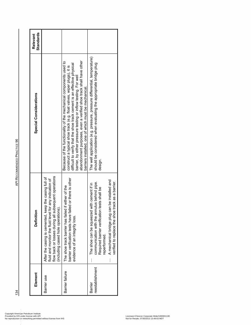
134
AP
I RE
CO
MM
EN
DE
D P
RA
CT
ICE
96
Ele
men
t D
efin
itio
n
Sp
ecia
l Co
nsi
der
atio
ns
Rel
eva
nt
Sta
nd
ard
s
Bar
rier
use
A
fter
the
casi
ng
is c
emen
ted,
kee
p th
e ca
sin
g fu
ll of
flu
id a
nd m
oni
tor
the
fluid
leve
l for
an
y in
dic
atio
n of
flo
w b
ack
or lo
sses
dur
ing
all s
ubse
quen
t op
erat
ions
(in
clu
ding
cas
ed
hole
op
erat
ions
).
Bar
rier
failu
re
The
sho
e tr
ack
barr
ier
has
faile
d if
eith
er o
f the
ba
rrie
r ve
rific
atio
n te
sts
have
faile
d or
ther
e is
oth
er
evid
ence
of a
n in
tegr
ity lo
ss.
Bec
ause
of t
he fu
nctio
nalit
y of
the
mec
han
ica
l com
pone
nts
use
d to
co
nstr
uct
a ty
pica
l sho
e tr
ack
(e.g
. flo
at v
alve
s, w
iper
plu
gs),
it is
di
fficu
lt to
ver
ify t
hat
the
shoe
tra
ck c
emen
t is
an e
ffect
ive
ph
ysic
al
barr
ier,
by
eith
er p
ress
ure
test
ing
or in
flow
test
ing.
For
we
ll ab
and
onm
ent
pur
pos
es, e
ven
a ve
rifie
d sh
oe
trac
k sh
all h
ave
oth
er
barr
iers
inst
alle
d, o
ne o
f w
hic
h m
ust b
e m
ech
anic
al.
Bar
rier
re
esta
blis
hmen
t —
T
he s
hoe
can
be s
quee
zed
with
cem
ent i
f in
com
mun
icat
ion
with
the
annu
lus
beh
ind
pip
e.
Req
uire
d ba
rrie
r ve
rific
atio
n te
sts
shal
l be
repe
rfor
med
.
—
A m
echa
nic
al b
ridge
plu
g ca
n be
inst
alle
d a
nd
verif
ied
to r
epla
ce th
e sh
oe tr
ack
as a
bar
rie
r.
The
wel
l app
licat
ion
(e.g
. pre
ssur
e, p
ress
ure
diffe
rent
ial,
tem
pera
ture
) sh
ould
be
cons
ider
ed w
hen
eva
luat
ing
the
appr
opria
te b
ridg
e pl
ug
desi
gn.
Copyright American Petroleum Institute Provided by IHS under license with API Licensee=Chevron Corporate Wide/1000001100
Not for Resale, 07/30/2013 13:49:03 MDTNo reproduction or networking permitted without license from IHS
--``,,`,````,``,`,``,,,`,,``,`-`-`,,`,,`,`,,`---
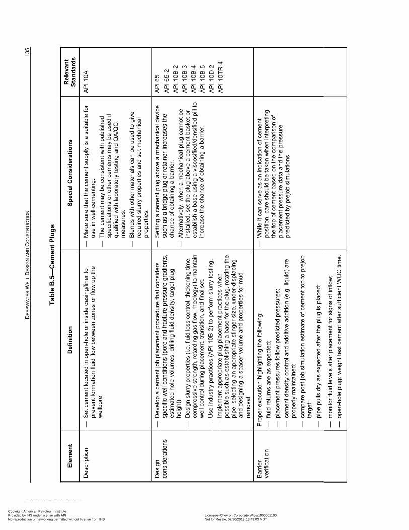
D
EE
PW
AT
ER
WE
LL D
ES
IGN
AN
D C
ON
ST
RU
CT
ION
13
5
Tab
le B
.5—
Cem
ent
Plu
gs
Ele
men
t D
efin
itio
n
Sp
ecia
l Co
nsi
der
atio
ns
Rel
eva
nt
Sta
nd
ard
s
Des
crip
tion
—
Set
cem
ent l
ocat
ed in
ope
n-h
ole
or in
sid
e ca
sing
/line
r to
pr
eve
nt fo
rmat
ion
fluid
flo
w b
etw
een
zo
nes
or fl
ow
up
the
we
llbor
e.
— M
ake
sure
that
the
cem
ent s
upp
ly is
a s
uita
ble
for
use
in w
ell
cem
entin
g.
— T
he c
emen
t ma
y be
con
sist
ent
with
pub
lish
ed
spec
ifica
tions
or
othe
r ce
me
nts
ma
y be
use
d if
qu
alif
ied
with
labo
rato
ry te
stin
g an
d Q
A/Q
C
mea
sure
s.
— B
len
ds w
ith o
ther
mat
eria
ls c
an
be u
sed
to g
ive
requ
ired
slur
ry p
rop
ertie
s a
nd s
et m
echa
nic
al
prop
ertie
s.
AP
I 10A
Des
ign
cons
ider
atio
ns
— D
evel
op a
cem
ent j
ob p
lace
men
t pro
cedu
re th
at c
onsi
ders
sp
ecifi
c w
ell
cond
ition
s (p
ore
and
frac
ture
pre
ssur
e gr
adie
nts
, es
timat
ed h
ole
volu
mes
, dril
ling
fluid
den
sity
, ta
rget
plu
g he
ight
).
— D
esig
n sl
urry
pro
pert
ies
(i.e.
flui
d lo
ss c
ontr
ol, t
hick
enin
g tim
e,
com
pres
sive
str
engt
h, r
etar
ding
gas
flow
, rhe
olog
y) to
mai
ntai
n w
ell c
ontr
ol d
urin
g pl
acem
ent,
tran
sitio
n, a
nd fi
nal s
et.
— U
se in
dust
ry p
ract
ices
(A
PI 1
0B
-2)
to p
erfo
rm s
lurr
y te
stin
g.
— I
mpl
eme
nt a
ppro
pria
te p
lug
plac
eme
nt p
ract
ices
wh
en
poss
ible
suc
h as
est
ablis
hing
a b
ase
for
the
plu
g, r
otat
ing
the
pip
e, s
elec
ting
an a
ppr
opr
iate
stin
ger
size
, un
der-
disp
laci
ng
and
des
igni
ng a
spa
cer
volu
me
and
prop
ertie
s fo
r m
ud
rem
oval
.
— S
ettin
g a
cem
ent
plu
g a
bove
a m
echa
nica
l dev
ice
such
as
a br
idg
e pl
ug
or r
etai
ner
incr
eas
es th
e ch
ance
of o
btai
nin
g a
barr
ier.
— A
ltern
ativ
ely,
whe
n a
mec
hani
cal p
lug
cann
ot b
e in
stal
led,
set
the
plu
g ab
ove
a c
emen
t bas
ket
or
esta
blis
h a
bas
e us
ing
a vi
sco
sifie
d/d
ensi
fied
pill
to
incr
eas
e th
e ch
ance
of o
btai
nin
g a
barr
ier.
AP
I 65
AP
I 65
-2
AP
I 10
B-2
AP
I 10
B-3
AP
I 10
B-4
AP
I 10
B-5
AP
I 10
D-2
AP
I 10T
R-4
Bar
rier
verif
icat
ion
Pro
per
exe
cutio
n hi
ghlig
htin
g th
e fo
llow
ing:
— f
luid
ret
urns
are
as
exp
ecte
d;
— p
lace
men
t pre
ssur
es fo
llow
pre
dict
ed
pres
sure
s;
— c
emen
t de
nsity
con
trol
an
d ad
ditiv
e a
dditi
on (
e.g.
liqu
id)
are
prop
erly
mai
ntai
ned
;
— c
ompa
re p
ost j
ob s
imu
latio
n e
stim
ate
of c
emen
t top
to p
rejo
b ta
rget
;
— p
ipe
pulls
dry
as
expe
cted
afte
r th
e pl
ug is
pla
ced;
— W
hile
it c
an s
erv
e as
an
indi
catio
n of
cem
en
t po
sitio
n, c
are
shou
ld b
e ta
ken
wh
en in
terp
retin
g th
e to
p of
cem
ent b
ase
d on
the
com
par
iso
n o
f pl
acem
ent p
ress
ure
data
and
the
pres
sure
pr
edic
ted
by
prej
ob
sim
ulat
ion
s.
— m
onito
r flu
id le
vels
afte
r pl
ace
men
t for
sig
ns o
f inf
low
;
— o
pen-
hole
plu
g:
wei
ght t
est c
emen
t af
ter
suffi
cien
t W
OC
tim
e.
Copyright American Petroleum Institute Provided by IHS under license with API Licensee=Chevron Corporate Wide/1000001100
Not for Resale, 07/30/2013 13:49:03 MDTNo reproduction or networking permitted without license from IHS
--``,,`,````,``,`,``,,,`,,``,`-`-`,,`,,`,`,,`---
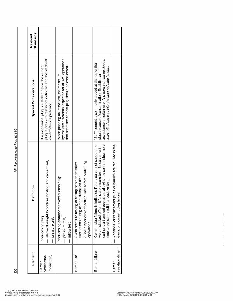
136
AP
I RE
CO
MM
EN
DE
D P
RA
CT
ICE
96
Ele
men
t D
efin
itio
n
Sp
ecia
l Co
nsi
der
atio
ns
Rel
eva
nt
Sta
nd
ard
s
Bar
rier
verif
icat
ion
(con
tinue
d)
Inne
r-ca
sing
plu
g:
— s
lack
-off
we
ight
to
conf
irm lo
catio
n a
nd c
emen
t set
,
— p
ress
ure
test
.
If a
mec
hani
cal p
lug
is in
stal
led
belo
w th
e ce
men
t pl
ug,
a p
ress
ure
test
is n
ot d
efin
itive
and
the
slac
k-of
f co
nfirm
atio
n is
pre
ferr
ed.
Inne
r-ca
sing
aba
ndo
nmen
t/eva
cuat
ion
plu
g:
— p
ress
ure
test
,
— i
nflo
w te
st.
Whe
n pl
anni
ng
an
inflo
w te
st, t
he m
axi
mum
h
ydro
stat
ic d
iffer
entia
l exp
ecte
d fo
r al
l we
ll o
pera
tions
th
at a
ffect
the
cem
ent p
lug
shou
ld b
e co
nsid
ered
.
Bar
rier
use
—
Avo
id p
ress
ure
test
ing
of c
asin
g or
oth
er p
ress
ure
fluct
uatio
ns d
urin
g ce
men
t tra
nsiti
on
time.
— A
llow
pro
per
cem
ent s
ettin
g tim
e be
fore
co
ntin
uing
op
erat
ions
.
Bar
rier
failu
re
— C
eme
nt p
lug
failu
re is
ind
icat
ed
if th
e pl
ug
cann
ot s
uppo
rt th
e w
eig
ht s
lack
ed o
ff or
if it
fai
ls a
pre
ssur
e te
st. S
ince
cem
ent
curin
g is
a tr
ansi
ent o
per
atio
n,
allo
win
g th
e ce
men
t plu
g m
ore
tim
e to
set
can
res
ult i
n a
posi
tive
test
.
“Sof
t” c
emen
t is
com
mon
ly ta
gge
d at
the
top
of t
he
plu
g be
caus
e o
f co
ntam
inat
ion
. E
stab
lish
an
acce
pta
nce
crite
rion
(e.g
. fin
d ha
rd c
emen
t no
deep
er
than
1/3
of t
he w
ay in
to th
e pl
anne
d pl
ug le
ngth
).
Bar
rier
re
esta
blis
hmen
t —
Add
ition
al o
r re
plac
emen
t plu
gs
or b
arrie
rs a
re r
equ
ired
in th
e ev
ent o
f a c
emen
t plu
g fa
ilure
.
Copyright American Petroleum Institute Provided by IHS under license with API Licensee=Chevron Corporate Wide/1000001100
Not for Resale, 07/30/2013 13:49:03 MDTNo reproduction or networking permitted without license from IHS
--``,,`,````,``,`,``,,,`,,``,`-`-`,,`,,`,`,,`---
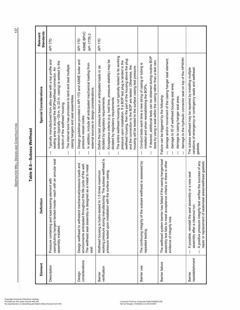
D
EE
PW
AT
ER
WE
LL D
ES
IGN
AN
D C
ON
ST
RU
CT
ION
13
7
Tab
le B
.6—
Su
bse
a W
ellh
ead
Ele
men
t D
efin
itio
n
Sp
ecia
l Co
nsi
der
atio
ns
Rel
eva
nt
Sta
nd
ard
s
Des
crip
tion
Pre
ssur
e co
ntai
ning
and
load
-bea
ring
elem
ent w
ith
casi
ng/tu
bing
han
gers
land
ed in
side
—ea
ch w
ith a
n an
nula
r se
al
asse
mbl
y in
stal
led.
—
Typ
ical
ly m
anuf
actu
red
from
allo
y st
eel w
ith a
top
prof
ile a
nd
seal
ing
area
to a
ccep
t the
BO
P/w
ellh
ead
conn
ecto
r. A
n ex
tens
ion
(typ
ical
ly ~
20-in
. to
22-
in. c
asin
g) is
wel
ded
to th
e bo
ttom
of t
he w
ellh
ead
hous
ing.
—
The
inte
rnal
bor
e ha
s pr
ovis
ions
to la
nd a
nd s
eal m
ultip
le
casi
ng h
ange
rs a
nd s
eal a
ssem
blie
s.
AP
I 17D
Des
ign
cons
ider
atio
ns
Des
ign
wel
lhea
d to
with
stan
d m
echa
nica
l/pre
ssur
e lo
ads
and
envi
ronm
ents
ant
icip
ated
thro
ugho
ut th
e lif
e cy
cle
of th
e w
ell.
The
wel
lhea
d se
al a
ssem
bly
is d
esig
ned
as a
met
al to
met
al
seal
.
—
Des
ign
guid
elin
es p
rovi
ded
in A
PI 1
7D a
nd A
SM
E b
oile
r an
d pr
essu
re v
esse
l cod
es.
—
In a
dditi
on, i
nclu
de a
ll an
ticip
ated
mec
hani
cal l
oadi
ng fr
om
exte
rnal
sou
rces
in d
esig
n co
nsid
erat
ions
.
AP
I 17D
AS
ME
BP
VC
AP
I 17T
R-3
Bar
rier
verif
icat
ion
Wel
lhea
d ho
usin
g is
hyd
ro-t
este
d to
1.5
tim
es m
axim
um
wor
king
pre
ssur
e du
ring
man
ufac
turin
g. T
he s
ubse
a w
ellh
ead
is
pres
sure
test
ed u
pon
inst
alla
tion
with
the
sur
face
cas
ing.
—
Def
ine
the
test
pre
ssur
e ba
sed
on a
ntic
ipat
ed lo
ads
or a
s di
ctat
ed b
y re
gula
tory
req
uire
men
ts.
—
Acc
epta
nce
crite
ria (
e.g.
hol
d tim
e, p
ress
ure
stab
ility
) m
ay
be
dict
ated
by
regu
lato
ry r
equi
rem
ents
.
—
The
ent
ire w
ellh
ead
hous
ing
is n
ot ty
pica
lly t
este
d to
its
wor
king
pr
essu
re u
pon
inst
alla
tion.
If a
BO
P te
st p
lug
is la
nded
in th
e w
ellh
ead
hous
ing,
then
the
part
of t
he h
ousi
ng a
bove
the
plug
an
d th
e co
nnec
tion
to th
e B
OP
are
test
ed. O
the
rwis
e, t
he
hous
ing
will
be
test
ed to
the
surf
ace
casi
ng te
st p
ress
ure.
AP
I 17D
Bar
rier
use
The
con
tinui
ng in
tegr
ity o
f th
e su
bsea
wel
lhea
d is
ass
esse
d by
re
peat
ed te
stin
g.
—
Con
duct
test
s ea
ch ti
me
a ne
w s
trin
g of
cas
ing
or tu
bing
is
inst
alle
d an
d w
hen
ree
stab
lishi
ng th
e B
OP
s.
—
If d
esire
d, a
dditi
onal
test
s ca
n be
obt
aine
d du
ring
rout
ine
BO
P
test
s b
y us
ing
a se
al w
ithin
the
casi
ng r
athe
r th
an a
test
ram
.
Bar
rier
failu
re
The
wel
lhea
d sy
stem
bar
rier
has
faile
d if
the
casi
ng h
ange
r/se
al
asse
mbl
y te
st f
ails
to m
eet a
ccep
tanc
e cr
iteria
or
ther
e is
oth
er
evid
ence
of i
nteg
rity
loss
.
Fai
lure
can
be
trig
gere
d by
the
follo
win
g:
—
dam
age
and/
or m
ovem
ent o
f the
cas
ing
hang
er s
eal e
lem
ent;
—
dam
age
to ID
of
wel
lhea
d ho
usin
g se
al a
rea;
—
dam
age
to c
asin
g ha
nger
sea
l are
a;
—
dam
age
to th
e h
ydra
ulic
con
nect
or s
eal o
n to
p of
the
HP
WH
H.
Bar
rier
re
esta
blis
hmen
t —
If
poss
ible
, rei
nsta
ll th
e se
al a
ssem
bly
or a
new
sea
l as
sem
bly
afte
r a
clea
nout
run
.
—
A p
ositi
ve p
ress
ure
inte
grity
tes
t ver
ifies
the
succ
ess
of a
ny
repa
ir or
rep
lace
men
t of s
eals
/sea
l are
as/w
ellh
ead
gask
ets.
The
sub
sea
wel
lhea
d m
ay b
e re
paire
d by
inst
allin
g m
ultip
le
varia
tions
of e
mer
genc
y or
con
tinge
ncy
seal
s an
d w
ellh
ead
gask
ets.
Copyright American Petroleum Institute Provided by IHS under license with API Licensee=Chevron Corporate Wide/1000001100
Not for Resale, 07/30/2013 13:49:03 MDTNo reproduction or networking permitted without license from IHS
--``,,`,````,``,`,``,,,`,,``,`-`-`,,`,,`,`,,`---
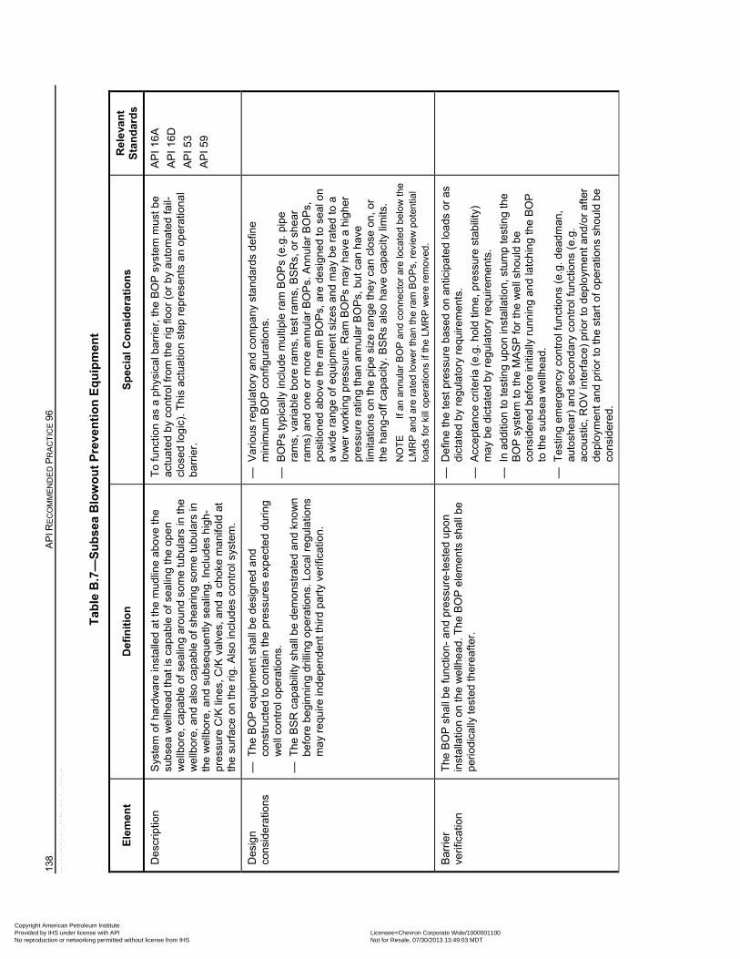
138
AP
I RE
CO
MM
EN
DE
D P
RA
CT
ICE
96
Tab
le B
.7—
Su
bse
a B
low
ou
t P
reve
nti
on
Eq
uip
men
t
Ele
men
t D
efin
itio
n
Sp
ecia
l Co
nsi
der
atio
ns
Rel
eva
nt
Sta
nd
ard
s
Des
crip
tion
S
yste
m o
f har
dw
are
inst
alle
d at
the
mud
line
abov
e th
e su
bse
a w
ellh
ead
that
is c
apa
ble
of s
ealin
g th
e op
en
we
llbor
e, c
apa
ble
of s
ealin
g a
roun
d so
me
tubu
lars
in th
e w
ellb
ore,
and
als
o ca
pab
le o
f she
arin
g so
me
tubu
lars
in
the
wel
lbor
e, a
nd s
ubse
que
ntly
se
alin
g. In
clu
des
high
-pr
essu
re C
/K li
nes,
C/K
val
ves,
and
a c
hoke
man
ifold
at
the
surf
ace
on
the
rig. A
lso
incl
udes
con
trol
sys
tem
.
To
func
tion
as a
ph
ysic
al b
arri
er, t
he B
OP
sys
tem
mus
t be
actu
ated
by
cont
rol f
rom
the
rig
floor
(or
by
aut
omat
ed fa
il-cl
ose
d lo
gic
). T
his
actu
atio
n st
ep r
epre
sent
s an
op
erat
iona
l ba
rrie
r.
AP
I 16A
AP
I 16
D
AP
I 53
AP
I 59
Des
ign
cons
ider
atio
ns
— T
he B
OP
equ
ipm
ent s
hall
be
desi
gne
d an
d co
nstr
ucte
d to
con
tain
the
pre
ssur
es e
xpec
ted
duri
ng
we
ll co
ntro
l op
erat
ions
.
— T
he B
SR
cap
abili
ty s
hal
l be
dem
onst
rate
d a
nd k
now
n
befo
re b
egin
nin
g dr
illin
g o
pera
tions
. Loc
al r
egu
latio
ns
ma
y re
quire
inde
pen
dent
thir
d pa
rty
verif
icat
ion.
— V
ario
us r
egu
lato
ry a
nd c
ompa
ny
sta
ndar
ds d
efin
e m
inim
um B
OP
con
figur
atio
ns.
— B
OP
s ty
pica
lly in
clu
de m
ulti
ple
ram
BO
Ps
(e.g
. pip
e ra
ms,
var
iab
le b
ore
ram
s, te
st r
ams,
BS
Rs,
or
shea
r ra
ms)
and
one
or
mor
e an
nula
r B
OP
s. A
nnul
ar B
OP
s,
posi
tione
d ab
ove
the
ram
BO
Ps,
are
des
ign
ed to
sea
l on
a w
ide
rang
e o
f eq
uipm
ent s
izes
and
ma
y b
e r
ated
to a
lo
wer
wo
rkin
g pr
essu
re. R
am B
OP
s m
ay h
ave
a h
ighe
r pr
essu
re r
atin
g th
an a
nnu
lar
BO
Ps,
but
can
hav
e lim
itatio
ns o
n th
e pi
pe s
ize
rang
e th
ey
can
clos
e on
, or
the
han
g-of
f ca
paci
ty. B
SR
s al
so h
ave
capa
city
lim
its.
NO
TE
If an
ann
ular
BO
P a
nd c
onne
ctor
are
loca
ted
belo
w th
e LM
RP
and
are
ra
ted
low
er th
an
the
ram
BO
Ps,
rev
iew
pot
entia
l lo
ads
for
kill
oper
atio
ns if
the
LMR
P w
ere
rem
oved
.
Bar
rier
verif
icat
ion
The
BO
P s
hall
be fu
nctio
n- a
nd
pres
sure
-tes
ted
upon
in
stal
latio
n on
the
we
llhea
d. T
he B
OP
ele
me
nts
shal
l be
perio
dica
lly te
sted
ther
eafte
r.
— D
efin
e th
e te
st p
ress
ure
base
d on
ant
icip
ate
d lo
ads
or
as
dict
ated
by
reg
ulat
ory
requ
ire
men
ts.
— A
ccep
tanc
e cr
iteria
(e.
g. h
old
time,
pre
ssur
e st
abili
ty)
ma
y b
e di
ctat
ed
by
regu
lato
ry r
equi
rem
ents
.
— I
n ad
ditio
n to
test
ing
upo
n in
stal
latio
n, s
tum
p te
stin
g th
e B
OP
sys
tem
to th
e M
AS
P fo
r th
e w
ell
shou
ld b
e co
nsid
ere
d be
fore
initi
ally
run
nin
g an
d la
tchi
ng th
e B
OP
to
the
subs
ea
we
llhe
ad.
— T
estin
g em
erg
ency
con
tro
l fun
ctio
ns (
e.g.
dea
dman
, au
tosh
ear)
and
sec
ond
ary
con
trol
func
tions
(e.
g.
acou
stic
, RO
V in
terf
ace)
pri
or t
o de
plo
yme
nt a
nd/o
r af
ter
dep
loym
ent
an
d pr
ior
to th
e st
art o
f ope
ratio
ns
shou
ld b
e co
nsid
ere
d.
Copyright American Petroleum Institute Provided by IHS under license with API Licensee=Chevron Corporate Wide/1000001100
Not for Resale, 07/30/2013 13:49:03 MDTNo reproduction or networking permitted without license from IHS
--``,,`,````,``,`,``,,,`,,``,`-`-`,,`,,`,`,,`---
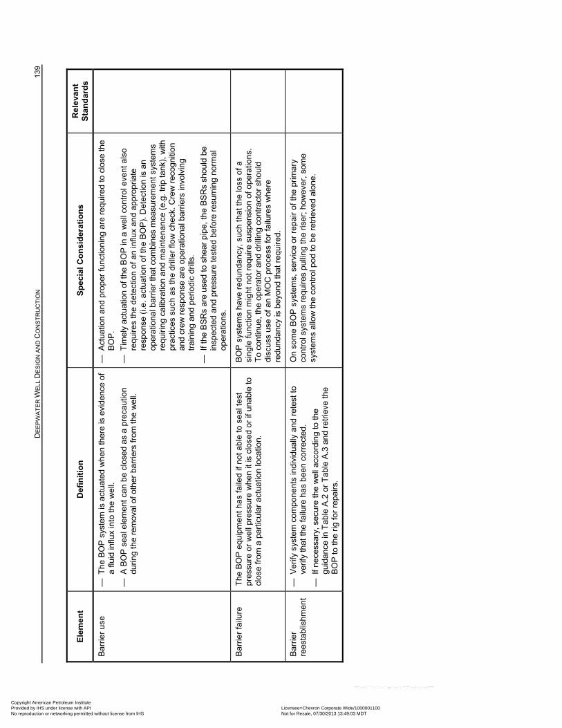
D
EE
PW
AT
ER
WE
LL D
ES
IGN
AN
D C
ON
ST
RU
CT
ION
13
9
Ele
men
t D
efin
itio
n
Sp
ecia
l Co
nsi
der
atio
ns
Rel
eva
nt
Sta
nd
ard
s
Bar
rier
use
—
The
BO
P s
yste
m is
act
uate
d w
he
n th
ere
is e
vide
nce
of
a flu
id in
flux
into
the
wel
l.
— A
BO
P s
eal e
lem
ent c
an b
e cl
osed
as
a pr
ecau
tion
duri
ng th
e re
mov
al o
f oth
er b
arrie
rs fr
om th
e w
ell.
— A
ctua
tion
and
pro
per
func
tion
ing
are
req
uire
d to
clo
se th
e B
OP
.
— T
imel
y ac
tuat
ion
of th
e B
OP
in a
we
ll co
ntro
l eve
nt a
lso
requ
ires
the
de
tect
ion
of a
n in
flux
and
appr
opria
te
resp
ons
e (i.
e. a
ctua
tion
of th
e B
OP
). D
etec
tion
is a
n op
erat
ion
al b
arrie
r th
at c
ombi
nes
mea
sure
men
t sys
tem
s re
quiri
ng
calib
ratio
n a
nd m
ain
tena
nce
(e.g
. trip
tank
), w
ith
prac
tices
suc
h as
the
drill
er fl
ow
ch
eck.
Cre
w r
ecog
nitio
n an
d cr
ew
res
pon
se a
re o
per
atio
nal b
arrie
rs in
volv
ing
trai
ning
an
d pe
riodi
c dr
ills.
— I
f the
BS
Rs
are
used
to s
hear
pip
e, th
e B
SR
s sh
ould
be
insp
ecte
d a
nd p
ress
ure
test
ed b
efor
e re
sum
ing
nor
mal
op
erat
ions
.
Bar
rier
failu
re
The
BO
P e
quip
men
t has
faile
d if
not a
ble
to s
eal t
est
pres
sure
or
we
ll pr
essu
re w
he
n it
is c
lose
d or
if u
nabl
e to
cl
ose
from
a p
artic
ular
act
uatio
n lo
catio
n.
BO
P s
yste
ms
have
re
dund
an
cy,
such
that
the
loss
of a
si
ngle
func
tion
mig
ht n
ot r
equi
re s
uspe
nsio
n of
ope
ratio
ns.
To
cont
inue
, the
ope
rato
r an
d dr
illin
g co
ntra
ctor
sho
uld
di
scus
s us
e of
an
MO
C p
roce
ss fo
r fa
ilure
s w
her
e re
dund
anc
y is
be
yond
that
re
quir
ed.
Bar
rier
re
esta
blis
hmen
t —
Ver
ify s
yste
m c
ompo
nent
s in
divi
dual
ly a
nd r
etes
t to
verif
y th
at th
e fa
ilure
has
bee
n co
rrec
ted.
— I
f nec
essa
ry, s
ecur
e th
e w
ell
acco
rdin
g to
the
guid
ance
in T
able
A.2
or
Tab
le A
.3 a
nd r
etrie
ve th
e B
OP
to th
e rig
for
repa
irs.
On
som
e B
OP
sys
tem
s, s
ervi
ce o
r re
pair
of th
e pr
imar
y co
ntro
l sys
tem
s re
quir
es p
ullin
g th
e ris
er; h
ow
eve
r, s
ome
syst
ems
allo
w t
he c
ontr
ol p
od
to b
e re
trie
ved
alo
ne.
Copyright American Petroleum Institute Provided by IHS under license with API Licensee=Chevron Corporate Wide/1000001100
Not for Resale, 07/30/2013 13:49:03 MDTNo reproduction or networking permitted without license from IHS
--``,,`,````,``,`,``,,,`,,``,`-`-`,,`,,`,`,,`---
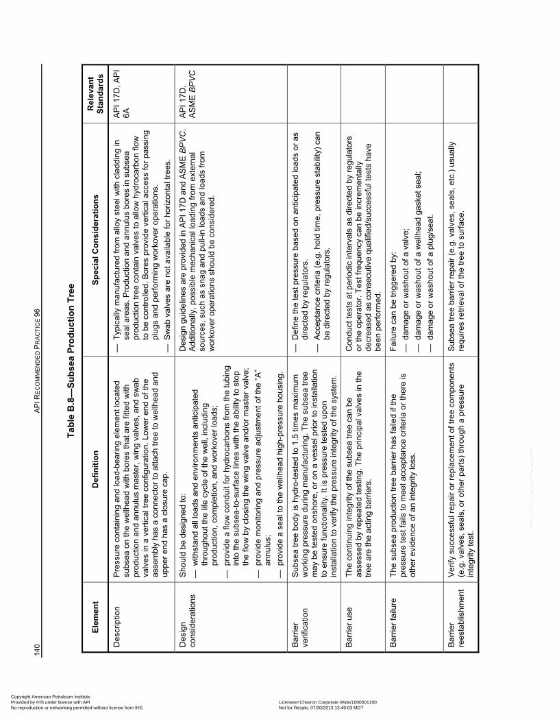
140
AP
I RE
CO
MM
EN
DE
D P
RA
CT
ICE
96
Tab
le B
.8—
Su
bse
a P
rod
uct
ion
Tre
e
Ele
men
t D
efin
itio
n
Sp
ecia
l Co
nsi
der
atio
ns
Rel
eva
nt
Sta
nd
ard
s
Des
crip
tion
P
ress
ure
cont
ain
ing
and
load
-bea
ring
ele
me
nt lo
cate
d su
bse
a on
the
we
llhe
ad w
ith b
ores
that
are
fitte
d w
ith
prod
uctio
n an
d a
nnu
lus
mas
ter,
win
g va
lves
, and
sw
ab
valv
es in
a v
ertic
al tr
ee c
onfig
urat
ion.
Lo
wer
end
of t
he
asse
mb
ly h
as a
con
nec
tor
to a
ttach
tree
to w
ellh
ead
and
up
per
en
d ha
s a
clos
ure
cap.
— T
ypic
ally
ma
nufa
ctur
ed fr
om a
lloy
stee
l with
cla
ddi
ng
in
seal
are
as. P
rodu
ctio
n an
d an
nulu
s bo
res
in s
ubse
a pr
oduc
tion
tre
e c
onta
in v
alv
es to
allo
w h
ydro
carb
on
flow
to
be
cont
rolle
d. B
ores
pro
vid
e ve
rtic
al a
cce
ss fo
r pa
ssin
g pl
ugs
an
d pe
rfor
min
g w
ork
over
ope
ratio
ns.
— S
wa
b va
lves
are
not
ava
ilabl
e fo
r ho
rizo
ntal
tree
s.
AP
I 17
D,
AP
I 6A
Des
ign
cons
ider
atio
ns
Sho
uld
be
desi
gne
d to
:
— w
ithst
and
all l
oad
s an
d en
viro
nmen
ts a
ntic
ipat
ed
thro
ugho
ut th
e lif
e cy
cle
of th
e w
ell,
incl
udin
g pr
oduc
tion,
co
mpl
etio
n, a
nd
wo
rkov
er lo
ads
;
— p
rovi
de a
flo
w c
ond
uit f
or h
ydro
carb
ons
from
the
tubi
ng
into
the
subs
ea-t
o-su
rfac
e lin
es
with
the
abili
ty to
sto
p th
e flo
w b
y cl
osi
ng th
e w
ing
valv
e a
nd/o
r m
ast
er v
alve
;
— p
rovi
de m
onito
ring
and
pre
ssur
e ad
just
men
t of
the
“A”
ann
ulus
;
— p
rovi
de a
se
al to
the
wel
lhea
d hi
gh-
pres
sure
hou
sing
.
Des
ign
guid
elin
es a
re p
rovi
ded
in A
PI 1
7D
and
AS
ME
BP
VC
. A
dditi
ona
lly, p
oss
ible
mec
hani
cal l
oad
ing
fro
m e
xter
nal
so
urce
s, s
uch
as s
nag
and
pul
l-in
load
s a
nd lo
ads
from
w
ork
over
ope
ratio
ns s
hou
ld b
e co
nsid
ere
d.
AP
I 17
D,
AS
ME
BP
VC
Bar
rier
verif
icat
ion
Sub
sea
tree
bo
dy
is h
ydro
-tes
ted
to 1
.5 ti
mes
max
imum
w
ork
ing
pres
sure
dur
ing
man
ufa
ctur
ing.
The
sub
sea
tree
m
ay
be
test
ed o
nsh
ore,
or
on a
ves
sel p
rior
to in
stal
latio
n to
ens
ure
func
tion
ality
. It i
s pr
essu
re te
sted
upo
n in
stal
latio
n to
ver
ify th
e pr
essu
re in
tegr
ity o
f the
sys
tem
.
— D
efin
e th
e te
st p
ress
ure
base
d on
ant
icip
ate
d lo
ads
or
as
dire
cte
d b
y re
gul
ator
s.
— A
ccep
tanc
e cr
iteria
(e.
g. h
old
time,
pre
ssur
e st
abili
ty)
can
be d
irec
ted
by
regu
lato
rs.
Bar
rier
use
T
he c
ontin
uing
inte
grity
of t
he s
ubse
a tr
ee c
an b
e as
sess
ed
by
repe
ate
d te
stin
g. T
he p
rinci
pal v
alve
s in
the
tree
are
the
actin
g b
arrie
rs.
Con
duct
test
s at
per
iodi
c in
terv
als
as d
irec
ted
by
regu
lato
rs
or th
e op
erat
or. T
est f
requ
ency
ca
n be
incr
em
enta
lly
decr
eas
ed a
s co
nsec
utiv
e q
ualif
ied/
succ
essf
ul te
sts
have
be
en
perf
orm
ed.
Bar
rier
failu
re
The
sub
sea
prod
uctio
n tr
ee b
arrie
r h
as fa
iled
if th
e pr
essu
re te
st fa
ils to
mee
t acc
epta
nce
crite
ria
or th
ere
is
othe
r ev
ide
nce
of a
n in
tegr
ity lo
ss.
Fai
lure
can
be
trig
gere
d b
y:
— d
ama
ge o
r w
ash
out o
f a v
alve
;
— d
ama
ge o
r w
ash
out o
f a w
ellh
ead
gask
et s
eal;
— d
ama
ge o
r w
ash
out o
f a p
lug
/sea
t.
Bar
rier
re
esta
blis
hmen
t V
erify
suc
cess
ful r
epai
r or
rep
lace
me
nt o
f tre
e co
mpo
nent
s (e
.g. v
alve
s, s
eal
s, o
r ot
her
pa
rts)
thro
ugh
a p
ress
ure
inte
grity
tes
t.
Sub
sea
tree
ba
rrie
r re
pair
(e.g
. val
ves,
sea
ls,
etc.
) us
ually
re
quire
s re
trie
val o
f the
tree
to s
urfa
ce.
Copyright American Petroleum Institute Provided by IHS under license with API Licensee=Chevron Corporate Wide/1000001100
Not for Resale, 07/30/2013 13:49:03 MDTNo reproduction or networking permitted without license from IHS
--``,,`,````,``,`,``,,,`,,``,`-`-`,,`,,`,`,,`---
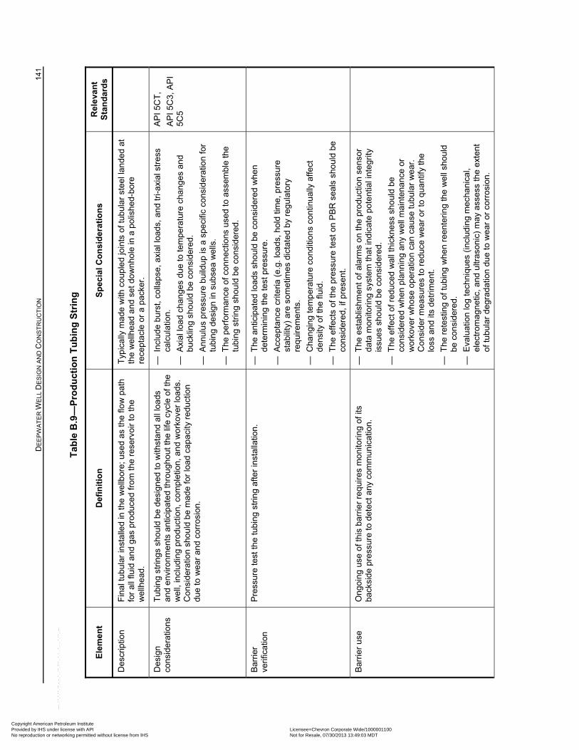
D
EE
PW
AT
ER
WE
LL D
ES
IGN
AN
D C
ON
ST
RU
CT
ION
14
1
Tab
le B
.9—
Pro
du
ctio
n T
ub
ing
Str
ing
Ele
men
t D
efin
itio
n
Sp
ecia
l Co
nsi
der
atio
ns
Rel
eva
nt
Sta
nd
ard
s
Des
crip
tion
F
inal
tub
ular
inst
alle
d in
the
wel
lbor
e; u
sed
as
the
flow
pat
h fo
r al
l flu
id a
nd
gas
pro
duce
d fr
om th
e re
serv
oir
to th
e w
ellh
ead
.
Typ
ical
ly m
ade
with
cou
ple
d jo
ints
of t
ubu
lar
stee
l lan
ded
at
the
wel
lhe
ad a
nd s
et d
ow
nh
ole
in a
po
lishe
d-bo
re
rece
ptac
le o
r a
pac
ker.
Des
ign
cons
ider
atio
ns
Tub
ing
strin
gs s
hou
ld b
e de
sign
ed
to w
ithst
and
all
loa
ds
and
env
ironm
ent
s an
ticip
ated
thr
oug
hout
the
life
cycl
e of
the
w
ell,
incl
udi
ng
prod
uctio
n, c
om
plet
ion,
an
d w
ork
over
loa
ds.
Con
side
ratio
n sh
ould
be
mad
e fo
r lo
ad c
apa
city
red
uctio
n du
e to
we
ar a
nd
corr
osio
n.
— I
nclu
de
burs
t, co
llaps
e, a
xial
load
s, a
nd
tri-a
xial
str
ess
calc
ulat
ion.
— A
xial
load
ch
ange
s du
e to
tem
pera
ture
cha
nges
and
bu
cklin
g sh
ould
be
cons
ider
ed.
— A
nnu
lus
pres
sure
bu
ildup
is a
spe
cific
con
sid
erat
ion
for
tubi
ng
desi
gn in
sub
sea
we
lls.
— T
he p
erfo
rman
ce o
f con
nec
tions
use
d to
ass
embl
e th
e tu
bin
g st
ring
shou
ld b
e co
nsid
ered
.
AP
I 5C
T,
AP
I 5C
3, A
PI
5C5
Bar
rier
verif
icat
ion
Pre
ssur
e te
st th
e tu
bing
str
ing
afte
r in
stal
latio
n.
— T
he a
ntic
ipat
ed
loa
ds s
houl
d be
con
sid
ered
wh
en
dete
rmin
ing
the
test
pre
ssur
e.
— A
ccep
tanc
e cr
iteria
(e.
g. lo
ad
s, h
old
time,
pre
ssur
e st
abili
ty)
are
som
etim
es d
icta
ted
by
reg
ulat
ory
requ
irem
ent
s.
— C
hang
ing
tem
per
atur
e co
nditi
ons
cont
inu
ally
affe
ct
dens
ity o
f the
flui
d.
— T
he e
ffect
s of
the
pres
sure
test
on
PB
R s
eals
sho
uld
be
cons
ider
ed,
if p
rese
nt.
Bar
rier
use
O
ngoi
ng u
se o
f thi
s ba
rrie
r re
qui
res
mo
nito
rin
g of
its
back
side
pre
ssur
e to
det
ect a
ny c
omm
unic
atio
n.
— T
he e
stab
lishm
ent o
f ala
rms
on
the
prod
uctio
n se
nsor
da
ta m
onito
ring
syst
em th
at in
dica
te p
ote
ntia
l int
egr
ity
issu
es s
hou
ld b
e co
nsid
ered
.
— T
he e
ffect
of r
educ
ed
wal
l thi
ckne
ss s
houl
d b
e co
nsid
ere
d w
hen
pla
nni
ng
any
we
ll m
aint
enan
ce o
r w
ork
over
wh
ose
oper
atio
n ca
n ca
use
tubu
lar
we
ar.
Con
side
r m
eas
ures
to r
educ
e w
ear
or
to q
ua
ntify
the
loss
an
d its
det
rimen
t.
— T
he r
etes
ting
of
tubi
ng w
hen
ree
nter
ing
the
we
ll sh
ould
be
con
sid
ered
.
— E
valu
atio
n lo
g te
chni
ques
(in
clud
ing
mec
hani
cal,
elec
trom
agn
etic
, and
ultr
aso
nic)
ma
y as
sess
the
ext
ent
of tu
bula
r d
egra
datio
n d
ue to
we
ar o
r co
rros
ion.
Copyright American Petroleum Institute Provided by IHS under license with API Licensee=Chevron Corporate Wide/1000001100
Not for Resale, 07/30/2013 13:49:03 MDTNo reproduction or networking permitted without license from IHS
--``,,`,````,``,`,``,,,`,,``,`-`-`,,`,,`,`,,`---
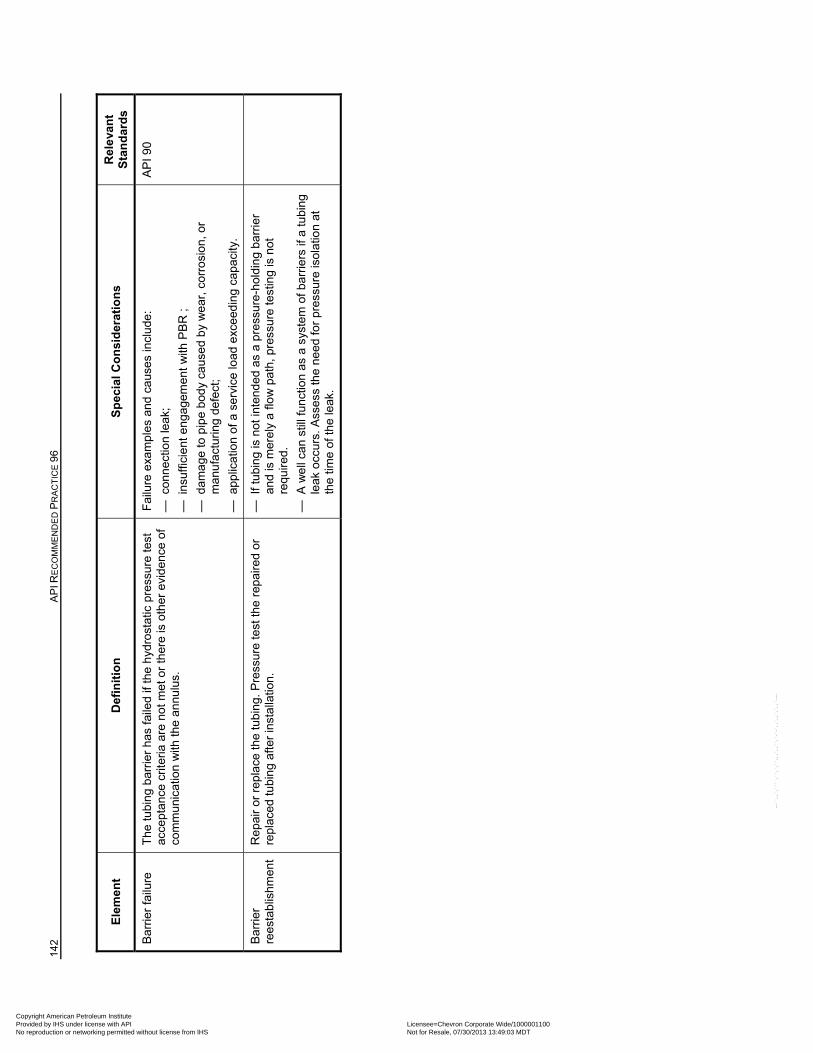
142
AP
I RE
CO
MM
EN
DE
D P
RA
CT
ICE
96
Ele
men
t D
efin
itio
n
Sp
ecia
l Co
nsi
der
atio
ns
Rel
eva
nt
Sta
nd
ard
s
Bar
rier
failu
re
The
tubi
ng b
arri
er h
as fa
iled
if th
e h
ydro
stat
ic p
ress
ure
test
ac
cept
anc
e cr
iteria
are
not
me
t or
ther
e is
oth
er e
vid
ence
of
com
mun
icat
ion
with
the
annu
lus.
Fai
lure
exa
mp
les
and
caus
es in
clu
de:
— c
onn
ectio
n le
ak;
— i
nsuf
ficie
nt e
ng
agem
ent
with
PB
R ;
— d
ama
ge to
pip
e bo
dy
caus
ed
by
we
ar, c
orro
sion
, or
man
ufac
turi
ng d
efec
t;
— a
pplic
atio
n of
a s
ervi
ce lo
ad e
xce
edin
g ca
paci
ty.
AP
I 90
Bar
rier
re
esta
blis
hmen
t R
epai
r or
rep
lace
the
tubi
ng. P
ress
ure
test
the
repa
ired
or
repl
aced
tubi
ng
afte
r in
stal
latio
n.
— I
f tub
ing
is n
ot in
tend
ed a
s a
pre
ssur
e-ho
ldin
g ba
rrie
r an
d is
mer
ely
a fl
ow
pat
h, p
ress
ure
test
ing
is n
ot
requ
ired.
— A
we
ll ca
n st
ill f
unct
ion
as a
sys
tem
of b
arri
ers
if a
tubi
ng
leak
occ
urs.
Ass
ess
the
need
for
pres
sure
iso
latio
n at
th
e tim
e of
the
leak
.
Copyright American Petroleum Institute Provided by IHS under license with API Licensee=Chevron Corporate Wide/1000001100
Not for Resale, 07/30/2013 13:49:03 MDTNo reproduction or networking permitted without license from IHS
--``,,`,````,``,`,``,,,`,,``,`-`-`,,`,,`,`,,`---
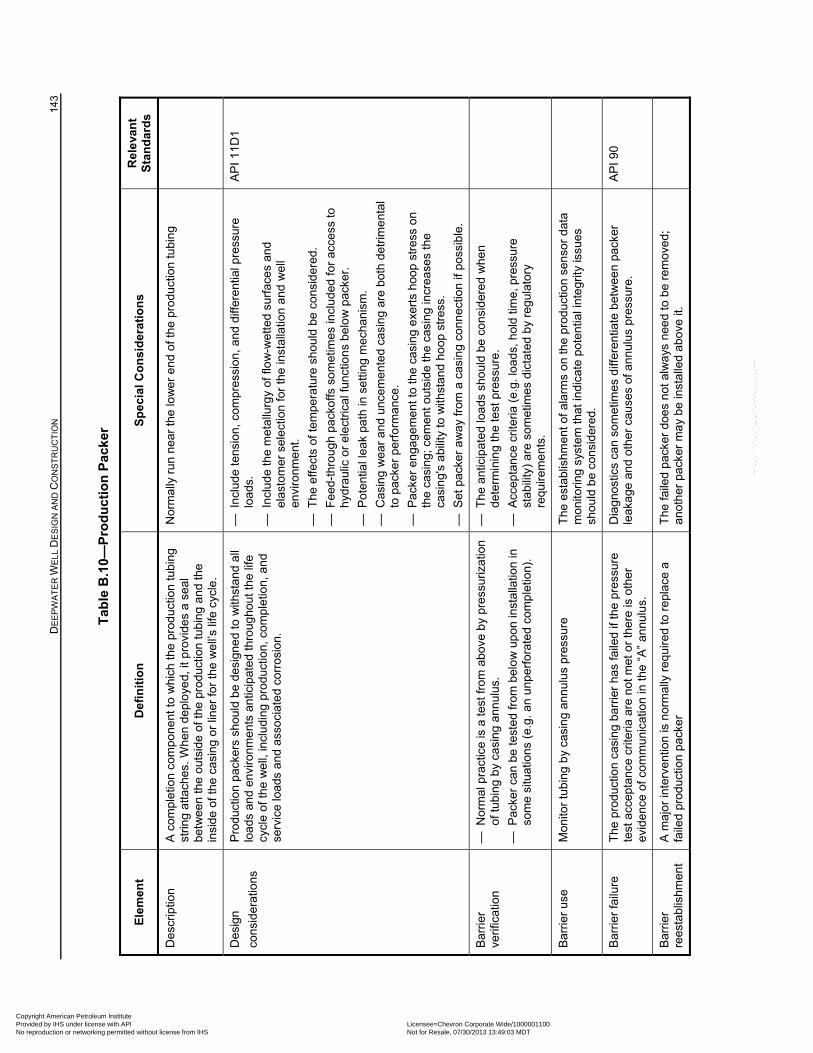
D
EE
PW
AT
ER
WE
LL D
ES
IGN
AN
D C
ON
ST
RU
CT
ION
14
3
Tab
le B
.10—
Pro
du
ctio
n P
acke
r
Ele
men
t D
efin
itio
n
Sp
ecia
l Co
nsi
der
atio
ns
Rel
eva
nt
Sta
nd
ard
s
Des
crip
tion
A
com
plet
ion
com
pone
nt to
whi
ch th
e pr
odu
ctio
n tu
bing
st
ring
atta
ches
. W
hen
dep
loye
d, it
pro
vide
s a
seal
be
twe
en th
e o
utsi
de o
f the
pro
duct
ion
tub
ing
and
the
insi
de
of th
e ca
sing
or
liner
for
the
we
ll’s
life
cycl
e.
Nor
mal
ly r
un n
ear
the
low
er
end
of t
he p
rodu
ctio
n tu
bing
Des
ign
cons
ider
atio
ns
Pro
duct
ion
pac
kers
sho
uld
be
desi
gne
d to
with
stan
d a
ll lo
ads
an
d en
viro
nme
nts
antic
ipat
ed th
roug
hout
the
life
cycl
e of
the
we
ll, in
clu
ding
pro
duct
ion,
com
plet
ion,
an
d se
rvic
e lo
ads
and
ass
ocia
ted
corr
osio
n.
— I
nclu
de
tens
ion
, co
mpr
essi
on,
and
diff
eren
tial p
ress
ure
load
s.
— I
nclu
de
the
me
tallu
rgy
of fl
ow
-wet
ted
surf
ace
s an
d el
asto
mer
sel
ect
ion
for
the
inst
alla
tion
and
wel
l en
viro
nme
nt.
— T
he e
ffect
s of
tem
pera
ture
sh
ould
be
cons
ider
ed.
— F
eed-
thro
ugh
pack
offs
som
etim
es in
clud
ed fo
r ac
cess
to
hyd
raul
ic o
r e
lect
rical
func
tion
s be
low
pac
ker.
— P
oten
tial l
eak
pat
h in
set
ting
mec
hani
sm.
— C
asin
g w
ear
and
unc
eme
nte
d ca
sin
g ar
e b
oth
detr
ime
ntal
to
pac
ker
perf
orm
ance
.
— P
acke
r en
gage
men
t to
the
casi
ng e
xert
s ho
op
stre
ss o
n th
e ca
sin
g; c
em
ent o
utsi
de
the
casi
ng in
crea
ses
the
casi
ng'
s ab
ility
to
with
stan
d ho
op s
tres
s.
— S
et p
acke
r a
wa
y fr
om a
cas
ing
conn
ectio
n if
poss
ible
.
AP
I 11
D1
Bar
rier
verif
icat
ion
— N
orm
al p
ract
ice
is a
test
from
abo
ve b
y pr
essu
rizat
ion
of tu
bing
by
casi
ng a
nnul
us.
— P
acke
r ca
n b
e te
sted
from
bel
ow
up
on in
stal
latio
n in
so
me
situ
atio
ns
(e.g
. an
unp
erf
orat
ed c
omp
letio
n).
— T
he a
ntic
ipat
ed
loa
ds s
houl
d be
con
sid
ered
wh
en
dete
rmin
ing
the
test
pre
ssur
e.
— A
ccep
tanc
e cr
iteria
(e.
g. lo
ad
s, h
old
time,
pre
ssur
e st
abili
ty)
are
som
etim
es d
icta
ted
by
reg
ulat
ory
requ
irem
ent
s.
Bar
rier
use
M
onito
r tu
bin
g b
y ca
sin
g an
nulu
s pr
essu
re
The
est
ablis
hmen
t of a
larm
s o
n th
e pr
oduc
tion
sens
or d
ata
mon
itori
ng s
yste
m th
at in
dica
te p
oten
tial i
nte
grity
issu
es
shou
ld b
e co
nsid
ered
.
Bar
rier
failu
re
The
pro
duct
ion
cas
ing
bar
rier
has
faile
d if
the
pre
ssur
e te
st a
ccep
tanc
e cr
iteria
are
not
met
or
ther
e is
oth
er
evid
ence
of c
omm
unic
atio
n in
the
“A”
annu
lus.
Dia
gno
stic
s ca
n so
met
imes
diff
eren
tiate
bet
we
en
pack
er
leak
age
and
othe
r ca
uses
of a
nnul
us p
ress
ure
. A
PI 9
0
Bar
rier
re
esta
blis
hmen
t A
maj
or in
terv
ent
ion
is n
orm
ally
req
uire
d to
re
plac
e a
faile
d pr
oduc
tion
pack
er
The
faile
d pa
cker
doe
s n
ot a
lwa
ys n
eed
to b
e r
emov
ed;
anot
her
pac
ker
ma
y b
e in
stal
led
abov
e it.
Copyright American Petroleum Institute Provided by IHS under license with API Licensee=Chevron Corporate Wide/1000001100
Not for Resale, 07/30/2013 13:49:03 MDTNo reproduction or networking permitted without license from IHS
--``,,`,````,``,`,``,,,`,,``,`-`-`,,`,,`,`,,`---
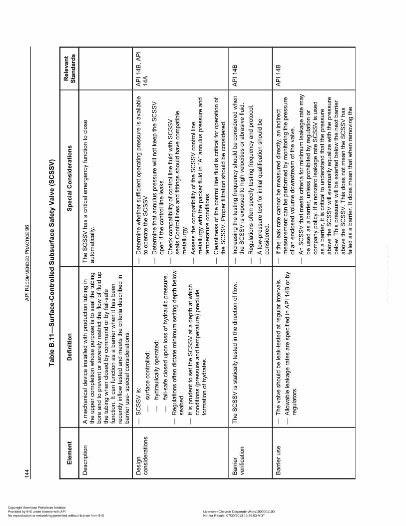
144
AP
I RE
CO
MM
EN
DE
D P
RA
CT
ICE
96
Tab
le B
.11—
Su
rfac
e-C
on
tro
lled
Su
bsu
rfac
e S
afet
y V
alve
(S
CS
SV
)
Ele
men
t D
efin
itio
n
Sp
ecia
l Co
nsi
der
atio
ns
Rel
eva
nt
Sta
nd
ard
s
Des
crip
tion
A
mec
han
ical
dev
ice
inst
alle
d w
ith p
rodu
ctio
n tu
bing
in
the
upp
er c
ompl
etio
n w
hos
e pu
rpos
e is
to s
eal t
he tu
bin
g bo
re a
nd to
pre
vent
or
seve
rely
res
tric
t the
flo
w o
f flu
id u
p th
e tu
bin
g w
he
n cl
ose
d b
y co
mm
and
or b
y fa
il-sa
fe
func
tion.
It c
an fu
nctio
n as
a b
arrie
r w
hen
it h
as b
een
rece
ntly
inflo
w t
este
d an
d m
eet
s th
e cr
iteria
des
crib
ed in
ba
rrie
r us
e- s
pec
ial c
onsi
dera
tions
.
The
SC
SS
V h
as a
crit
ical
em
erg
ency
func
tion
to c
lose
au
tom
atic
ally
.
Des
ign
cons
ider
atio
ns
— S
CS
SV
is:
—
surf
ace
cont
rolle
d;
—
hyd
raul
ical
ly o
pera
ted;
—
fail-
safe
clo
sed
upo
n lo
ss o
f hyd
rau
lic p
ress
ure
.
— R
egul
atio
ns o
ften
dic
tate
min
imum
set
ting
dep
th b
elo
w
seab
ed.
— I
t is
prud
ent t
o se
t the
SC
SS
V a
t a d
epth
at w
hic
h co
nditi
ons
(pre
ssur
e an
d te
mpe
ratu
re)
prec
lude
fo
rmat
ion
of h
ydra
tes.
— D
eter
min
e w
he
ther
suf
ficie
nt o
pera
ting
pres
sure
is a
vaila
ble
to
ope
rate
the
SC
SS
V.
— D
eter
min
e th
at a
nnu
lus
pres
sure
will
not
kee
p th
e S
CS
SV
op
en
if th
e co
ntr
ol li
ne
leak
s.
— C
heck
com
patib
ility
of c
ontr
ol l
ine
fluid
with
SC
SS
V
seal
s.C
ontr
ol li
nes
and
fittin
gs s
houl
d ha
ve c
ompa
tible
m
etal
lurg
y.
— A
sses
s th
e co
mpa
tibili
ty o
f the
SC
SS
V c
ontr
ol li
ne
met
allu
rgy
with
the
pack
er fl
uid
in "
A"
ann
ulu
s pr
essu
re a
nd
tem
pera
ture
co
nditi
ons.
— C
lea
nlin
ess
of t
he c
ontr
ol li
ne
fluid
is c
ritic
al fo
r op
erat
ion
of
the
SC
SS
V. P
rope
r fil
trat
ion
shou
ld b
e co
nsid
ere
d.
AP
I 14
B,
AP
I 14
A
Bar
rier
verif
icat
ion
The
SC
SS
V is
sta
tical
ly te
sted
in th
e di
rect
ion
of fl
ow
. —
Inc
reas
ing
the
test
ing
freq
uenc
y sh
ould
be
cons
ider
ed w
hen
the
SC
SS
V is
exp
osed
to h
igh
velo
citie
s or
abr
asiv
e flu
id.
— R
egul
atio
ns o
ften
spe
cify
test
ing
freq
uen
cy a
nd p
roto
col.
— A
low
-pre
ssur
e te
st fo
r in
itial
qua
lific
atio
n sh
oul
d b
e co
nsid
ere
d.
AP
I 14B
Bar
rier
use
— T
he v
alve
sho
uld
be
leak
-tes
ted
at r
egul
ar in
terv
als.
— A
llow
ab
le le
akag
e ra
tes
are
spec
ified
in A
PI
14B
or
by
regu
lato
rs.
— I
f the
leak
rat
e ca
nnot
be
mea
sure
d d
irect
ly, a
n in
dire
ct
mea
sure
men
t ca
n be
per
form
ed b
y m
onito
ring
the
pres
sure
of
an
encl
ose
d vo
lum
e do
wn
stre
am o
f the
val
ve.
— A
n S
CS
SV
tha
t m
eets
crit
eria
for
min
imum
leak
age
rate
ma
y be
use
d as
a b
arrie
r, u
nle
ss p
rohi
bite
d b
y re
gula
tion
or
com
pan
y po
licy.
If a
non
zero
leak
age
rate
SC
SS
V is
use
d as
a b
arri
er, i
t is
criti
cal t
o un
der
stan
d th
at th
e pr
essu
re
abov
e th
e S
CS
SV
will
eve
ntu
ally
equ
aliz
e w
ith th
e pr
essu
re
belo
w. T
his
pres
sure
will
be
exe
rte
d be
low
the
next
bar
rier
ab
ove
the
SC
SS
V. T
his
does
not
mea
n th
e S
CS
SV
has
fa
iled
as a
bar
rier
. It d
oes
mea
n th
at w
hen
rem
ovin
g th
e
AP
I 14B
Copyright American Petroleum Institute Provided by IHS under license with API Licensee=Chevron Corporate Wide/1000001100
Not for Resale, 07/30/2013 13:49:03 MDTNo reproduction or networking permitted without license from IHS
--``,,`,````,``,`,``,,,`,,``,`-`-`,,`,,`,`,,`---
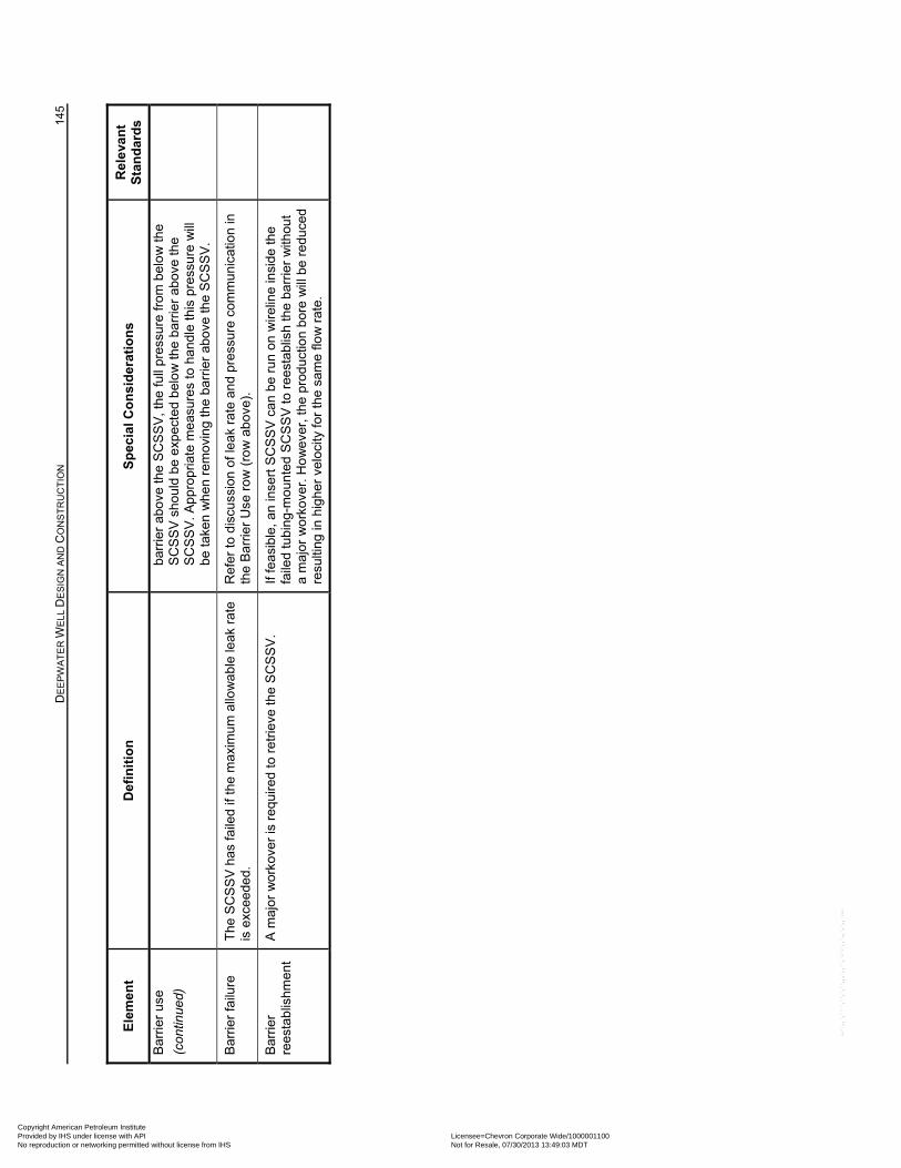
D
EE
PW
AT
ER
WE
LL D
ES
IGN
AN
D C
ON
ST
RU
CT
ION
14
5
Ele
men
t D
efin
itio
n
Sp
ecia
l Co
nsi
der
atio
ns
Rel
eva
nt
Sta
nd
ard
s
Bar
rier
use
(con
tinue
d)
barr
ier
abov
e th
e S
CS
SV
, the
full
pres
sure
from
bel
ow
the
SC
SS
V s
hou
ld b
e e
xpec
ted
bel
ow
the
barr
ier
abov
e th
e S
CS
SV
. App
ropr
iate
me
asur
es
to h
andl
e th
is p
ress
ure
will
be
take
n w
hen
rem
ovin
g th
e ba
rrie
r ab
ove
the
SC
SS
V.
Bar
rier
failu
re
The
SC
SS
V h
as fa
iled
if th
e m
axim
um a
llow
abl
e le
ak r
ate
is e
xcee
ded.
R
efer
to d
iscu
ssio
n of
leak
rat
e an
d pr
essu
re c
omm
unic
atio
n in
th
e B
arrie
r U
se r
ow
(ro
w a
bov
e).
Bar
rier
re
esta
blis
hmen
t A
maj
or w
orko
ver
is r
equi
red
to r
etrie
ve th
e S
CS
SV
. If
feas
ible
, an
inse
rt S
CS
SV
can
be
run
on w
irelin
e in
side
the
faile
d tu
bing
-mou
nte
d S
CS
SV
to r
eest
ablis
h th
e ba
rrie
r w
ithou
t a
maj
or w
ork
over
. Ho
wev
er, t
he p
rod
uctio
n b
ore
will
be
redu
ced
resu
lting
in h
ighe
r ve
loci
ty f
or t
he s
ame
flow
rat
e.
Copyright American Petroleum Institute Provided by IHS under license with API Licensee=Chevron Corporate Wide/1000001100
Not for Resale, 07/30/2013 13:49:03 MDTNo reproduction or networking permitted without license from IHS
--``,,`,````,``,`,``,,,`,,``,`-`-`,,`,,`,`,,`---
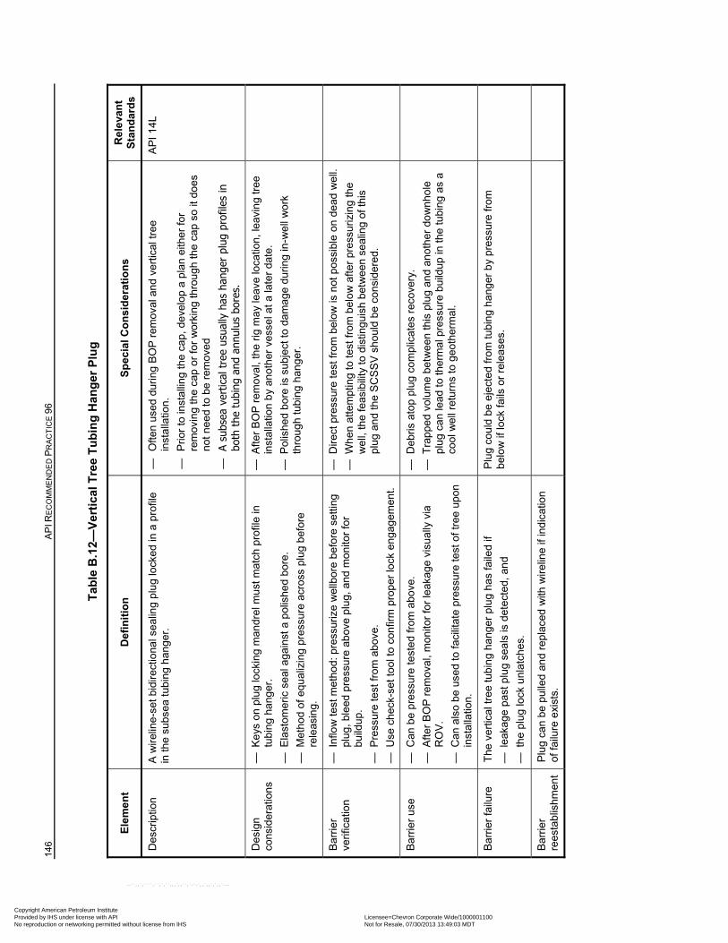
146
AP
I RE
CO
MM
EN
DE
D P
RA
CT
ICE
96
Tab
le B
.12—
Ver
tica
l Tre
e T
ub
ing
Han
ger
Plu
g
Ele
men
t D
efin
itio
n
Sp
ecia
l Co
nsi
der
atio
ns
Rel
eva
nt
Sta
nd
ard
s
Des
crip
tion
A
wir
elin
e-se
t bid
irec
tiona
l se
alin
g pl
ug lo
cked
in a
pro
file
in th
e su
bsea
tub
ing
han
ger
. —
O
ften
used
dur
ing
BO
P r
emov
al a
nd
vert
ical
tre
e in
stal
latio
n.
—
Prio
r to
inst
allin
g th
e ca
p, d
eve
lop
a pl
an e
ither
for
rem
ovin
g th
e ca
p or
for
wor
king
thro
ugh
the
cap
so it
do
es
not n
eed
to b
e re
mov
ed
—
A su
bsea
ver
tical
tre
e us
ually
has
han
ger
plug
pro
files
in
both
the
tub
ing
and
annu
lus
bore
s.
AP
I 14
L
Des
ign
cons
ider
atio
ns
— K
eys
on
plug
lock
ing
man
drel
mus
t mat
ch p
rofil
e in
tu
bin
g ha
nger
.
— E
last
omer
ic s
eal
ag
ains
t a p
olis
hed
bore
.
— M
etho
d of
equ
aliz
ing
pres
sure
acr
oss
plug
bef
ore
rele
asin
g.
— A
fter
BO
P r
emov
al, t
he r
ig m
ay
leav
e lo
catio
n, le
avin
g tr
ee
inst
alla
tion
by
anot
her
ves
sel a
t a la
ter
date
.
— P
olis
hed
bor
e is
sub
ject
to d
am
age
dur
ing
in-w
ell
wo
rk
thro
ugh
tubi
ng h
ange
r.
Bar
rier
verif
icat
ion
— I
nflo
w te
st m
etho
d: p
ress
uriz
e w
ellb
ore
befo
re s
ettin
g pl
ug,
ble
ed p
ress
ure
abov
e p
lug,
and
mo
nito
r fo
r bu
ildu
p.
— P
ress
ure
test
from
abo
ve.
— U
se c
heck
-set
tool
to c
onfir
m p
rop
er lo
ck e
nga
gem
ent.
— D
irect
pre
ssur
e te
st fr
om b
elow
is n
ot p
ossi
ble
on d
ead
we
ll.
— W
hen
atte
mpt
ing
to te
st fr
om b
elo
w a
fter
pre
ssur
izin
g th
e w
ell,
the
feas
ibili
ty to
dis
tingu
ish
betw
een
se
alin
g of
this
pl
ug a
nd th
e S
CS
SV
sho
uld
be c
onsi
dere
d.
Bar
rier
use
—
Can
be
pres
sure
test
ed fr
om a
bove
.
— A
fter
BO
P r
emov
al, m
onito
r fo
r le
akag
e vi
sual
ly v
ia
RO
V.
— C
an a
lso
be
used
to fa
cilit
ate
pres
sure
test
of t
ree
upon
in
stal
latio
n.
— D
ebris
ato
p pl
ug c
ompl
icat
es r
ecov
ery.
— T
rapp
ed v
olum
e be
twe
en th
is p
lug
and
anot
her
do
wn
hole
pl
ug
can
lead
to
ther
mal
pre
ssur
e bu
ildup
in th
e tu
bin
g as
a
cool
we
ll re
turn
s to
geo
ther
ma
l.
Bar
rier
failu
re
The
ver
tical
tree
tubi
ng
hang
er
plug
has
faile
d if
— l
eaka
ge p
ast p
lug
sea
ls is
det
ecte
d, a
nd
— t
he p
lug
lock
unl
atch
es.
Plu
g co
uld
be e
ject
ed
from
tubi
ng
hang
er b
y pr
essu
re fr
om
belo
w if
lock
fails
or
rele
ases
.
Bar
rier
re
esta
blis
hmen
t P
lug
can
be p
ulle
d an
d re
plac
ed w
ith w
irelin
e if
indi
catio
n of
fai
lure
exi
sts.
Copyright American Petroleum Institute Provided by IHS under license with API Licensee=Chevron Corporate Wide/1000001100
Not for Resale, 07/30/2013 13:49:03 MDTNo reproduction or networking permitted without license from IHS
--``,,`,````,``,`,``,,,`,,``,`-`-`,,`,,`,`,,`---
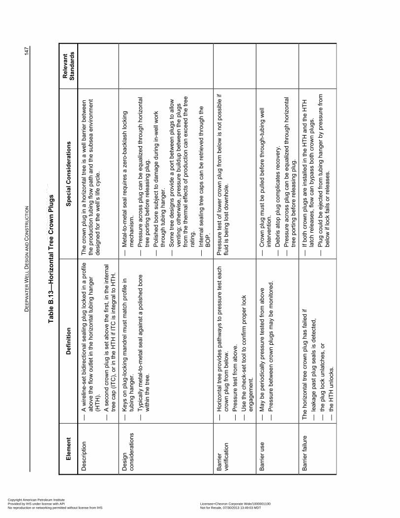
D
EE
PW
AT
ER
WE
LL D
ES
IGN
AN
D C
ON
ST
RU
CT
ION
14
7
Tab
le B
.13—
Ho
rizo
nta
l Tre
e C
row
n P
lug
s
Ele
men
t D
efin
itio
n
Sp
ecia
l Co
nsi
der
atio
ns
Rel
eva
nt
Sta
nd
ard
s
Des
crip
tion
—
A w
irel
ine-
set b
idir
ectio
nal s
eal
ing
plug
lock
ed in
a p
rofil
e ab
ove
the
flow
out
let i
n th
e ho
rizon
tal t
ubin
g ha
nge
r (H
TH
).
— A
sec
ond
cro
wn
plu
g is
set
ab
ove
the
first
, in
the
inte
rnal
tr
ee c
ap (
ITC
), o
r in
the
HT
H if
ITC
is in
tegr
al t
o H
TH
.
The
cro
wn
plu
g in
a h
oriz
ont
al tr
ee is
a w
ell
barr
ier
bet
wee
n th
e pr
oduc
tion
tubi
ng
flow
pat
h an
d th
e su
bsea
env
ironm
ent
desi
gne
d fo
r th
e w
ell’
s lif
e cy
cle.
Des
ign
cons
ider
atio
ns
— K
eys
on
plug
-loc
kin
g m
andr
el m
ust m
atch
pro
file
in
tubi
ng
hang
er.
— T
ypic
ally
met
al-t
o-m
etal
sea
l aga
inst
a p
olis
hed
bor
e w
ithin
the
tree
.
— M
etal
-to-
met
al s
eal r
equ
ires
a z
ero-
back
lash
lock
ing
mec
hani
sm.
— P
ress
ure
acro
ss p
lug
can
be e
qua
lize
d th
rou
gh h
oriz
onta
l tr
ee p
ortin
g be
fore
rel
easi
ng p
lug.
— P
olis
hed
bor
e su
bjec
t to
dam
age
dur
ing
in-w
ell
wo
rk
thro
ugh
tubi
ng h
ange
r.
— S
ome
tree
des
igns
pro
vide
a p
ort b
etw
een
plu
gs to
allo
w
vent
ing;
oth
erw
ise,
pre
ssur
e b
uild
up b
etw
een
the
plug
s fr
om th
e th
erm
al e
ffect
s of
pro
duct
ion
can
exc
eed
the
tre
e ra
ting.
— I
nter
nal s
eal
ing
tree
cap
s ca
n be
ret
rieve
d th
roug
h th
e B
OP
.
Bar
rier
verif
icat
ion
— H
oriz
ont
al tr
ee p
rovi
des
path
wa
ys to
pre
ssur
e te
st e
ach
cro
wn
plu
g fr
om
bel
ow
.
— P
ress
ure
test
from
abo
ve.
— U
se th
e ch
eck-
set t
ool t
o co
nfir
m p
rope
r lo
ck
eng
agem
ent.
Pre
ssur
e te
st o
f lo
we
r cr
ow
n p
lug
from
be
low
is n
ot p
ossi
ble
if flu
id is
bei
ng
lost
do
wnh
ole.
Bar
rier
use
—
Ma
y b
e pe
riod
ical
ly p
ress
ure
test
ed fr
om a
bo
ve
— P
ress
ure
bet
wee
n cr
ow
n p
lug
s m
ay
be
mon
itore
d.
— C
row
n pl
ug
mu
st b
e pu
lled
bef
ore
thro
ugh
-tu
bin
g w
ell
inte
rven
tion.
— D
ebris
ato
p pl
ug c
ompl
icat
es r
ecov
ery.
— P
ress
ure
acro
ss p
lug
can
be e
qua
lize
d th
rou
gh h
oriz
onta
l tr
ee p
ortin
g be
fore
rel
easi
ng p
lug.
Bar
rier
failu
re
The
hor
izon
tal t
ree
cro
wn
plu
g ha
s fa
iled
if
— l
eaka
ge p
ast p
lug
sea
ls is
det
ecte
d,
— t
he p
lug
lock
unl
atch
es, o
r
— t
he H
TH
unl
ocks
.
— I
f bot
h cr
ow
n pl
ugs
are
inst
alle
d in
the
HT
H a
nd th
e H
TH
la
tch
rele
ases
, flo
w c
an b
ypas
s bo
th c
row
n p
lugs
.
— P
lug
coul
d be
eje
cte
d fr
om tu
bin
g ha
nger
by
pres
sure
from
be
low
if lo
ck fa
ils o
r re
leas
es.
Copyright American Petroleum Institute Provided by IHS under license with API Licensee=Chevron Corporate Wide/1000001100
Not for Resale, 07/30/2013 13:49:03 MDTNo reproduction or networking permitted without license from IHS
--``,,`,````,``,`,``,,,`,,``,`-`-`,,`,,`,`,,`---
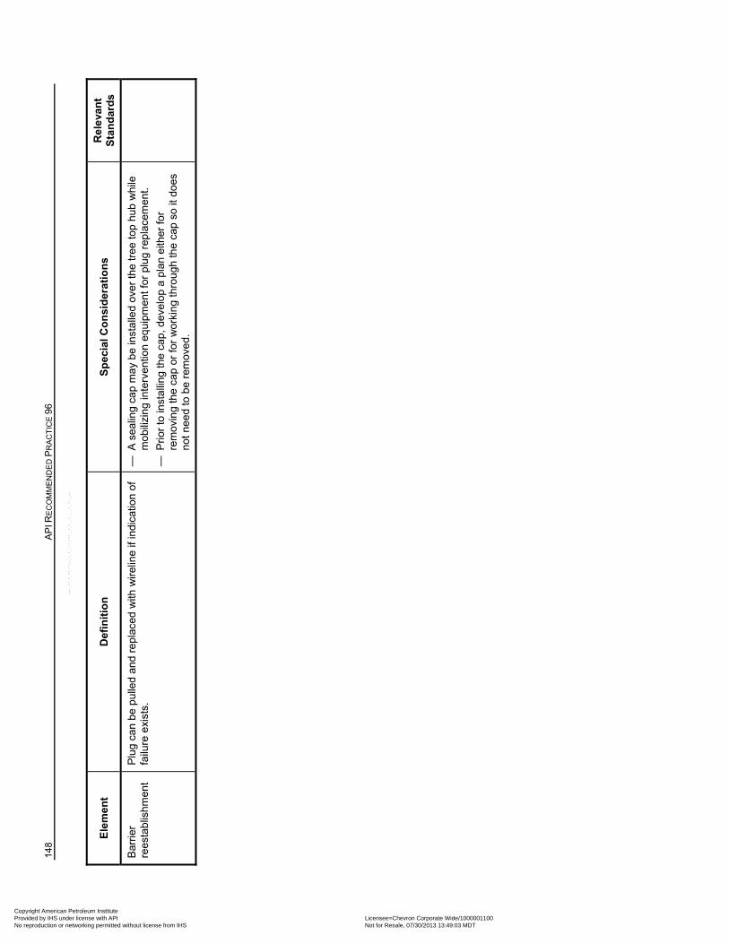
148
AP
I RE
CO
MM
EN
DE
D P
RA
CT
ICE
96
Ele
men
t D
efin
itio
n
Sp
ecia
l Co
nsi
der
atio
ns
Rel
eva
nt
Sta
nd
ard
s
Bar
rier
re
esta
blis
hmen
t P
lug
can
be p
ulle
d an
d re
plac
ed w
ith w
irelin
e if
indi
catio
n o
f fa
ilure
exi
sts.
—
A s
ealin
g ca
p m
ay
be
inst
alle
d ov
er th
e tr
ee t
op h
ub w
hile
m
obili
zin
g in
terv
entio
n eq
uipm
ent f
or p
lug
rep
lace
men
t.
— P
rior
to in
stal
ling
the
cap,
de
velo
p a
plan
eith
er fo
r re
mov
ing
the
cap
or fo
r w
orki
ng th
rou
gh th
e ca
p so
it d
oes
no
t nee
d to
be
rem
ove
d.
Copyright American Petroleum Institute Provided by IHS under license with API Licensee=Chevron Corporate Wide/1000001100
Not for Resale, 07/30/2013 13:49:03 MDTNo reproduction or networking permitted without license from IHS
--``,,`,````,``,`,``,,,`,,``,`-`-`,,`,,`,`,,`---
149
Annex C (informative)
Examples of Inflow Testing
C.1 General
This annex includes a series of examples of operational procedures for conducting inflow testing of barriers in DW wells. An inflow test typically involves disabling the hydrostatic barrier above the physical barrier to be tested by reducing the hydrostatic fluid head. This creates a net pressure load against the physical barrier in the direction of flow from the subsurface formations into the well.
Each example procedure below suggests a method of maintaining well control by replacing the hydrostatic barrier with a mechanical barrier (e.g. packer, test ram, BOP test tool, etc.), prior to conducting the actual inflow test. The starting point for the following examples is a well with hydrostatic overbalance, tested BOPs and a new barrier system installed but not tested. Annex C is intended to provide a basis for the development of inflow test procedures. The examples provided represent accepted oilfield practices and do not address every possible operation or well configuration.
Guiding principles that should be considered when planning and conducting an inflow test are as follows.
a) The inflow test pressure shall meet/exceed the maximum underbalance that the well will be exposed to.
b) Install and verify that a primarily testing barrier such as a packer or closed pipe ram is effective prior to disabling the hydrostatic barrier during an inflow test.
c) Always use the primarily testing barrier element to hold pressure in the direction it is designed for (e.g. test rams hold pressure from above, conventional rams hold pressure from below). If the test fluid is displaced below the testing barrier (i.e. test rams, packer) then U-tubing from the annulus below the barrier to the testing string can occur. This could cause a vacuum to form below the testing barrier and make results difficult to interpret.
d) If taking flow through the FOSV on the drill pipe to the choke manifold and to the mud-gas separator, ensure flow path is clear (i.e. no check valve or drill pipe float is present).
e) Always be prepared for the barrier to fail the inflow test and a subsequent well control event to occur. Have plans established and communicated in the event the barrier fails the inflow test and maintain sufficient volume of fluid of the original density in the mud pits to quickly restore the original fluid barrier.
f) Test deeper barriers using the Example 1 procedures prior to testing shallow barriers to reduce impact of potential influx due to deeper barrier failure.
g) Check that shearable tubulars are across the BSR(s) as applicable.
h) The fluid used to create the underbalance for inflow testing should be appropriately inhibitive to the formation of hydrates (e.g. inhibited seawater or NAF).
The following operations are described in this annex:
— inflow test of downhole barriers using a retrievable packer (refer to Example 1);
— inflow test of a wellhead seal assembly with a BOP test ram (refer to Example 2):
Copyright American Petroleum Institute Provided by IHS under license with API Licensee=Chevron Corporate Wide/1000001100
Not for Resale, 07/30/2013 13:49:03 MDTNo reproduction or networking permitted without license from IHS
--``,,`,````,``,`,``,,,`,,``,`-`-`,,`,,`,`,,`---
150 API RECOMMENDED PRACTICE 96
— inflow test without a BOP test ram utilizing the riser displacement to seawater method for testing a barrier system which includes a wellhead seal assembly (refer to Example 3);
— inflow test of a wellhead seal assembly with a BOP test tool (refer Example 4).
C.2 Example 1: Inflow Test of Downhole Barriers using a Retrievable Packer
The following generic description illustrates an example of an inflow test using a retrievable packer for testing submudline barriers, such as a newly set liner hanger. This test will not put a collapse differential across the BOPs, but does require a trip with a mechanical packer to isolate the annulus. It can be used to generate a higher inflow test pressure downhole than procedures that displace fluid down the choke or kill lines. Procedures may include the following.
1) Run a packer into the well on pipe to just above the barrier(s) to be tested. Do not set the packer yet. Do not position the packer in a previous shoe track.
2) Install a tested FOSV on the drill pipe. Make up and test surface lines from FOSV to choke manifold.
3) Displace the inside of the pipe with enough of the less-dense fluid to create the desired inflow test pressure at the depth of the barrier (i.e. typically sea water or base oil). The choke manifold is used to trap the surface pressure prior to setting the packer.
4) Set the packer and verify that it is sealing by closing an annular BOP and pressure testing the casing by drill pipe annulus (with the FOSV open and the choke manifold valves closed) and setting weight on the packer or conducting a pull test. Then bleed the annulus pressure to a lower value and monitor this pressure during the inflow test.
5) Bleed off the pressure inside the drill pipe through choke manifold and the mud gas separator at a slow rate and record bleed-off volume versus surface pressure. Once the drill pipe pressure is bled off, monitor flowback volume in the trip tank for a sufficient time to evaluate results (e.g. 30 minutes). Due to thermal effects of mud, a Horner plot may be necessary to evaluate the results of the inflow test, which would require monitoring shut-in pressure at the choke manifold versus time.
If the barriers pass the inflow test, perform the following:
1) Repressurize the drill pipe with the cementing unit to achieve a pressure balance on the packer.
2) Unseat the packer.
3) Reverse out the low density test fluid in the drill pipe with hydrostatic barrier fluid through the choke manifold. As a precaution, monitor returns for an indication of gas, especially with NAF fluids.
4) Verify that the well is static on the drill pipe and choke line, then open the pipe rams.
5) Rig down the line from the drill pipe to the choke manifold.
6) Continue to the next operation.
If the barriers fail the inflow test, put hydrostatic barrier fluid back into the well and circulate out any influx as follows.
1) Repressurize the low-density test fluid in the drill pipe with the cementing unit to achieve a pressure balance on packer.
Copyright American Petroleum Institute Provided by IHS under license with API Licensee=Chevron Corporate Wide/1000001100
Not for Resale, 07/30/2013 13:49:03 MDTNo reproduction or networking permitted without license from IHS
--``,,`,````,``,`,``,,,`,,``,`-`-`,,`,,`,`,,`---
DEEPWATER WELL DESIGN AND CONSTRUCTION 151
2) Unseat the packer. Line-up to reverse or circulate out, refer to the well control policy per operator’s SEMS.
3) Circulate out the low-density test fluid with mud through the choke manifold and gas buster using back pressure to maintain an overbalance. Determine if any influx has entered or is continuing to enter the well after the test.
NOTE If influx entered the well, refer to company well control policy.
4) Verify that the well is static on the drill pipe and choke line, then open the annular BOP.
5) Rig down the line from the drill pipe to the choke manifold.
6) Continue to the next operation (barrier repair or perform a MOC before resuming normal operations).
NOTE An inflow test performed on multiple physical barriers in series cannot verify each individual barrier. For example, an inflow test on a multi-valve shoe track with set cement cannot individually demonstrate performance of the valves or the cement, only that the combination of these barriers is performing. However, the presence of multiple barriers in series increases well reliability.
C.3 Example 2: Inflow Test of a Wellhead Seal Assembly with a BOP Test Ram
The following generic description illustrates an example of an inflow test on a Wellhead Seal Assembly using a BOP test ram. The BOP test ram is designed to hold pressure from above. This feature allows for use of pipe rams to perform inflow testing. For example, DW stack configurations may consist of annular, BSR, casing shear rams, variable bore rams, pipe rams, and test rams (test rams are normally run in the bottom cavity of the BOP stack). Procedures may include the following.
1) Run the drill pipe to below the wellhead.
2) Install a FOSV on the drill pipe. Make up and test surface lines from FOSV to choke.
3) Displace the inside of the pipe with enough of the less-dense fluid to create the desired inflow test pressure at the depth of the barrier (i.e. typically sea water or base oil).
4) Close the test ram.
5) Close a pipe ram and pressure-up down the choke line between the test ram and the pipe ram to verify that the test ram is holding pressure. The BOP test pressure should be greater than the desired inflow test pressure at the depth of the barrier. Hold test pressure between the test ram and the pipe ram and monitor the choke line pressure during the inflow test (FOSV is open).
6) Bleed off the pressure inside the drill pipe to choke manifold and the mud gas separator at a slow rate and record bleed-off volume versus surface pressure. Once the drill pipe pressure is bled off, monitor flowback volume in the trip tank for a sufficient time to evaluate results (e.g. 30 minutes). Monitor the riser fluid level during the inflow test. The level should remain static. Due to thermal effects of mud, a Horner plot may be necessary to evaluate the results of the inflow test, which would require monitoring shut-in pressure at the choke manifold versus time.
7) If the seal assembly passes the inflow test, perform the following.
— Bleed off the pressure between the pipe ram and the test ram.
— Repressurize the low-density test fluid in the drill pipe with the cementing unit to the original drill pipe pressure prior to bleeding off to achieve a pressure balance on the test rams.
Copyright American Petroleum Institute Provided by IHS under license with API Licensee=Chevron Corporate Wide/1000001100
Not for Resale, 07/30/2013 13:49:03 MDTNo reproduction or networking permitted without license from IHS
--``,,`,````,``,`,``,,,`,,``,`-`-`,,`,,`,`,,`---
152 API RECOMMENDED PRACTICE 96
— Open the test ram.
— Reverse out the low density test fluid in the drill pipe with hydrostatic barrier fluid through the choke manifold.
— Verify that the well is static on the drill pipe and choke line, then open the pipe rams.
— Rig down the line from the drill pipe to the choke manifold.
— Continue to the next operation.
8) If the barrier fails the inflow test, put hydrostatic barrier fluid back into the well and circulate out any influx as follows.
— Bleed the pressure off between the test ram and the pipe ram.
— Repressurize the low-density test fluid in the drill pipe with the cementing unit to achieve a pressure balance on the test rams.
— Open the test ram. Line-up to reverse or circulate out, refer to the well control policy per operator’s SEMS.
— Circulate out the low-density test fluid with mud through the choke manifold and gas buster using back pressure to maintain an overbalance. Determine if any influx has entered or is continuing to enter the well after the test.
NOTE If influx entered the well, refer to company well control policy.
— Verify that the well is static on the drill pipe and choke line, then open the pipe rams.
— Rig down the line from the drill pipe to the choke manifold.
— Continue to the next operation (barrier repair or perform MOC before resuming normal operations).
NOTE This test is performed after deeper barriers have been tested. If using NAF based oil, review the BOPs pressure differential limit when external pressure exceeds internal BOP pressure, as some BOP parts may not be designed for external pressure.
C.4 Example 3: Inflow Test without a BOP Test Ram Utilizing the Riser Displacement to Seawater
The following generic description illustrates an example of an inflow test on a Wellhead Seal Assembly using a BOP without a test ram. If the pressures placed across the stack from a saltwater displacement down the drill pipe with mud in the riser exceeds the BOP elements rating, this alternative method equalizes the pressures across the riser and stack to that of seawater. It does require displacing the riser but can be performed with standard BOP elements. Procedures may include the following.
1) Run the drill pipe to the planned displacement point below the wellhead.
2) Install a FOSV on the drill pipe. Make up and test surface lines from FOSV to choke manifold.
3) Close upper-most pipe rams immediately below the upper choke line outlet.
Copyright American Petroleum Institute Provided by IHS under license with API Licensee=Chevron Corporate Wide/1000001100
Not for Resale, 07/30/2013 13:49:03 MDTNo reproduction or networking permitted without license from IHS
--``,,`,````,``,`,``,,,`,,``,`-`-`,,`,,`,`,,`---
DEEPWATER WELL DESIGN AND CONSTRUCTION 153
4) Displace the hydrostatic barrier fluid in the riser boost line to seawater. Close the riser boost line valve.
5) Initiate the displacement of the BOP and riser from hydrostatic barrier fluid with seawater through the upper choke line outlet. Once the hydrostatic barrier fluid interface is above the riser boost line, close the upper kill line valve, open the riser boost line valve and finish displacing the hydrostatic barrier fluid in the riser to sea water through with the riser boost line. Then close the riser boost line valve.
6) Displace the hydrostatic barrier fluid from the well bore below the pipe rams to seawater by normal circulation down the drill pipe and through the upper kill line outlet (immediately below the closed pipe ram). Maintain back pressure on the kill line during this displacement to keep the pressure below the closed pipe ram to that equivalent to the head of the hydrostatic barrier fluid displaced. Once the well bore is displaced to seawater, shut in the kill line at the choke manifold trapping the pressure below the closed pipe rams.
7) Perform inflow test by bleeding displacement pressure from upper kill line outlet at a slow rate to the choke manifold and the mud gas separator and record bleed-off volume versus surface pressure, while monitoring pressure on the drill pipe. Once pressure is bled off, monitor flowback volume from the kill line in the trip tank for a sufficient time to evaluate results (e.g. 30 minutes). Due to thermal effects of mud, a Horner plot may be necessary to evaluate the results of the inflow test, which would require monitoring shut-in pressure at the choke manifold versus time.
8) Monitor the riser fluid level during the inflow test to ensure level remains static.
9) If the barrier system passes the inflow test, perform the following:
— monitor well through the upper kill line to the trip tank to ensure well is static;
— line up BOP valves to normal operating positions and then open upper pipe ram;
— continue to the next operation.
10) If the barrier system fails the inflow test, put the hydrostatic barrier back into the well as follows.
— Evaluate the failure and perform kill operations as necessary.
— Repressurize the well bore below the upper pipe ram to the original hydrostatic barrier fluid head by pumping seawater down the drill pipe and against the kill line that is shut in at the choke manifold.
— Determine if any influx has entered or is continuing to enter the well after the test. Displace the seawater from the well bore below the lower pipe ram to hydrostatic barrier fluid by normal circulation down the drill pipe and through the upper kill line. Once the displacement to hydrostatic barrier fluid is completed, then shut down the pump and monitor the well through the kill line to the trip tank to ensure the well remains static.
NOTE Refer to the well control policy in accordance with operator’s SEMS. The well control policy may call for reversing the influx out instead of circulating it out.
— Open the riser boost line valve and displace the seawater from the riser boost line. Then close the riser boost line valve.
— Open the upper choke and initiate the displacement of the sea water from the riser to hydrostatic barrier fluid by normal circulation. Once the sea water has been displaced from the choke line and to above the riser boost line outlet, close the upper choke line valve, open the riser boost line
Copyright American Petroleum Institute Provided by IHS under license with API Licensee=Chevron Corporate Wide/1000001100
Not for Resale, 07/30/2013 13:49:03 MDTNo reproduction or networking permitted without license from IHS
--``,,`,````,``,`,``,,,`,,``,`-`-`,,`,,`,`,,`---
154 API RECOMMENDED PRACTICE 96
valve and finish displacing the seawater in the riser to hydrostatic barrier fluid. Then close the riser boost valve.
— If the well is static as monitored through the upper kill line, then line up BOP valves to normal operating positions, open the upper pipe rams, rig down the line from the drill pipe to the choke manifold and continue normal operations.
NOTE If the well is not static, then perform kill operations as per company well control policy.
— Assess the barrier failure and determine next steps (e.g. barrier repair or remediation).
C.5 EXAMPLE 4: Inflow Test of a Wellhead Seal Assembly with a BOP Test Tool
The following generic description illustrates an example of an inflow test for testing a wellhead seal assembly using a BOP test tool designed to seal in the HPWHH bore above the casing hanger or bore protector. This method isolates the riser from the wellhead seal assembly and eliminates the need for a riser displacement when test rams are not available.
1) Run the BOP test tool on drill pipe to just above the landing point in the wellhead.
2) Install a FOSV on the drill pipe. Make up the test surface lines from FOSV to choke and manifold.
3) Displace the inside of the pipe with enough of the less-dense fluid to create the desired inflow test pressure at the depth of the barrier (i.e. typically sea water or NAF based oil).
4) Seat the BOP test tool in the wellhead.
5) Close a pipe ram and pressure down the choke line between the BOP test tool and the pipe ram to verify that the BOP test tool is seated and holding pressure. Check that the BOP test pressure is greater than the desired inflow test pressure at the depth of the barrier. Hold test pressure between the BOP test tool and the pipe ram and monitor the choke line pressure during the underbalance test (FOSV is open).
6) Bleed off the pressure inside the drill pipe to choke manifold at a slow rate and record bleed-off volume versus surface pressure. Once the drill pipe pressure is bled off, monitor flowback volume in the trip tank for a sufficient time to evaluate results (e.g. 30 minutes). Monitor the riser fluid level during the inflow test to ensure level remains static. Due to thermal effects of mud, a Horner plot may be necessary to evaluate the results of the inflow test, which would require monitoring shut-in pressure at the choke manifold versus time.
7) If the seal assembly passes the inflow test, perform the following:
— bleed off the pressure between the pipe ram and then unseat the BOP test tool;
— repressurize the low density test fluid in the drill pipe with the cementing unit to the original drill pipe pressure prior to bleeding off to achieve a pressure balance on the BOP test tool;
— close an annular BOP and open the pipe ram;
— reverse out the low density test fluid in the drill pipe with mud through the choke manifold;
— verify that the well is static on the drill pipe and choke line, then open the annular BOP;
— rig down the line from the drill pipe to the choke manifold;
Copyright American Petroleum Institute Provided by IHS under license with API Licensee=Chevron Corporate Wide/1000001100
Not for Resale, 07/30/2013 13:49:03 MDTNo reproduction or networking permitted without license from IHS
--``,,`,````,``,`,``,,,`,,``,`-`-`,,`,,`,`,,`---
DEEPWATER WELL DESIGN AND CONSTRUCTION 155
— pull out of hole with the BOP test tool;
— continue to the next operation.
8) If the barrier fails the inflow test, put hydrostatic barrier fluid back into the well and circulate out any influx as follows.
— Bleed-off the pressure between the BOP test tool and the pipe ram up the choke line.
— Repressurize the low-density test fluid in the drill pipe with the cementing unit to achieve a pressure balance on BOP test tool.
— Close the annular BOP, open the pipe ram, and then unseat the BOP test tool.
— Circulate out the low-density test fluid with mud through the choke manifold and gas buster using back pressure to maintain an overbalance. Determine if any influx has entered or is continuing to enter the well after the test.
NOTE If the inflow test failed and an influx entered the well, refer to company well control policy per operator’s SEMS. The well control policy may call for reversing the influx out instead of circulating it out. Verify that the well is static on the drill pipe and choke line, then open the annular BOP.
— Rig down the line from the drill pipe to the choke manifold.
— Pull out of hole with the BOP test tool.
— Continue to the next operation (barrier repair or perform MOC before resuming normal operations).
NOTE This test is performed after deeper barriers have been tested. If using NAF based oil, review the BOPs pressure differential limit when external pressure exceeds internal BOP pressure, as some BOP components may not be designed for external pressure.
Copyright American Petroleum Institute Provided by IHS under license with API Licensee=Chevron Corporate Wide/1000001100
Not for Resale, 07/30/2013 13:49:03 MDTNo reproduction or networking permitted without license from IHS
--``,,`,````,``,`,``,,,`,,``,`-`-`,,`,,`,`,,`---
156
Bibliography
[1] 30 CFR 250 1, Federal Code of Regulations for Oil, Gas and Sulphur Operations in the OCS.
[2] API Bulletin 2INT-DG, Interim Guidance for Design of Offshore Structures for Hurricane Conditions
[3] API Bulletin 2INT-MET, Interim Guidance on Hurricane Conditions in the Gulf of Mexico
[4] API Recommended Practice 2A-WSD, Planning, Designing and Constructing Fixed Offshore Platforms—Working Stress Design
[5] API Recommended Practice 2RD, Design of Risers for Floating Production Systems (FPSs) and Tension-Leg Platforms (TLPs)
[6] API Recommended Practice 2SK, Design and Analysis of Stationkeeping Systems for Floating Structures
[7] API Recommended Practice 5C5, Recommended Practice on Procedures for Testing Casing and Tubing Connections, Third Edition
[8] API Specification 5CT, Specification for Casing and Tubing
[9] API Specification 5CRA, Specification for Corrosion Resistant Alloy Seamless Tubes for Use as Casing, Tubing and Coupling Stock
[10] API Technical Report 5C3, Technical Report on Equations and Calculations for Casing, Tubing, and Line Pipe used as Casing or Tubing; and Performance Properties Tables for Casing and Tubing
[11] API Specification 6A, Specification for Wellhead and Christmas Tree Equipment
[12] API Technical Report 6AF, Capabilities of API Flanges Under Combinations
[13] API Technical Report 6AF1, Technical Report on Temperature Derating of API Flanges of Combination Loading
[14] API Technical Report 6AF2, Technical Report on Capabilities of API Integral Flanges of Combination Loading—Phase II
[15] API Recommended Practice 7G, Recommended Practice for Drill Stem Design and Operating Limits, 16th Edition
[16] API Recommended Practice 7G-2, Recommended Practice for Drill Stem Element Inspection, First Edition
[17] API Recommended Practice 8B, Inspection, Maintenance, Repair, and Remanufacture of Hoisting Equipment
[18] API Specification 10A, Specification for Cements and Materials for Well Cementing
1 The U.S. Code of Federal Regulations, U.S. Government Printing Office, 732 North Capitol Street, NW, Washington, DC 20401-0001, www.gpo.gov/fdsys.
Copyright American Petroleum Institute Provided by IHS under license with API Licensee=Chevron Corporate Wide/1000001100
Not for Resale, 07/30/2013 13:49:03 MDTNo reproduction or networking permitted without license from IHS
--``,,`,````,``,`,``,,,`,,``,`-`-`,,`,,`,`,,`---
DEEPWATER WELL DESIGN AND CONSTRUCTION 157
[19] API Recommended Practice 10B-2, Recommended Practice for Testing Well Cements
[20] API Recommended Practice 10B-3, Recommended Practice on Testing of Deepwater Well Cement Formulations
[21] API Recommended Practice 10B-4, Recommended Practice on Preparation and Testing of Foamed Cement Slurries at Atmospheric Pressure
[22] API Recommended Practice 10B-5, Recommended Practice on Determination of Shrinkage and Expansion of Well Cement Formulations at Atmospheric Pressure
[23] API Recommended Practice 10D-2, Recommended Practice for Centralizer Placement and Stop Collar Testing
[24] API Recommended Practice 10F, Recommended Practice for Performance Testing of Cementing Float Equipment
[25] API Technical Report 10TR-1, Cement Sheath Evaluation
[26] API Technical Report 10TR-4, Selection of Centralizers for Primary Cementing Operations
[27] API Specification 11D1, Packers and Bridge Plugs
[28] API Recommended Practice 13B-1, Recommended Practice for Field Testing Water-Based Drilling Fluids
[29] API Recommended Practice 13B-2, Recommended Practice for Field Testing Oil-based Drilling Fluids
[30] API Specification 14A/ISO 10432, Specification for Subsurface Safety Valve Equipment
[31] API Recommended Practice 14B, Design, Installation, Repair and Operation of Subsurface Safety Valve Systems
[32] API Recommended Practice 14E, Recommended Practice for Design and Installation of Offshore Production Platform Piping systems
[33] API Specification 14L, Specification for Lock Mandrels and Landing Nipples
[34] API Specification 16A, Specification for Drill-through Equipment
[35] API Specification 16D, Specification for Control Systems for Drilling Well Control Equipment and Control Systems for Diverter Equipment
[36] API Recommended Practice 16Q, Design, Selection, Operation and Maintenance of Marine Drilling Riser Systems
[37] API Recommended Practice 16ST, Coiled Tubing Well Control Equipment Systems
[38] API Specification 17D, Subsea Wellhead and Christmas Tree Equipment
[39] API Technical Report 17TR-3, An Evaluation of the Risks and Benefits of Penetrations in Subsea Wellheads below the BOP Stack
[40] API Recommended Practice 59, Recommended Practice for Well Control Operations
[41] API Recommended Practice 65, Cementing Shallow Water Flow Zones in Deep Water Wells
[42] API Recommended Practice 65-2, Isolating Potential Flow Zones During Well Construction
Copyright American Petroleum Institute Provided by IHS under license with API Licensee=Chevron Corporate Wide/1000001100
Not for Resale, 07/30/2013 13:49:03 MDTNo reproduction or networking permitted without license from IHS
--``,,`,````,``,`,``,,,`,,``,`-`-`,,`,,`,`,,`---
158 API RECOMMENDED PRACTICE 96
[43] API Recommended Practice 75, Third Edition, Recommended Practice for Development of a Safety and Environmental Management Program (SEMP) for Offshore Operations and Facilities
[44] API Recommended Practice 90, Annular Casing Pressure Management for Offshore Wells
[45] API Recommended Practice 1111, Recommended Practice for the Design, Construction, Operation, and Maintenance of Offshore Hydrocarbon Pipelines (Limited State Design)
[46] ASTM C150 2, Standard Specification for Portland Cement
[47] DNV-RP-H101 3, Risk Management in Marine and Subsea Operations
[48] IADC HSE Case Guidelines, International Association of Drilling Contractors' Health, Safety and Environmental Case Guidelines for Mobile Offshore Drilling Units
[49] ISO 10426-6 4, Methods for Determining the Static Gel Strength of Cement Formulations
[50] ISO 28781, Petroleum and natural gas industries—Drilling and production equipment—Subsurface barrier valves and related equipment
[51] NACE MR0175/ISO 15156 5, Petroleum and Natural gas Industries—Materials for Use in H2S-Containing Environments in Oil and Gas Production
[52] NACE TM0177-2005, Laboratory Testing of Metals for Resistance to Sulfide Stress Cracking and Stress Corrosion Cracking in H2S Environments
[53] NORSOK Standard D-010 6, Well integrity in drilling and well operations
[54] Eaton, L.F., Drilling Through Shallow Water Flow Zones at Ursa, paper SPE/IADC 52780 presented at the 1999 SPE/IADC Drilling Conference, Amsterdam, 9–11 March
[55] Energy Technology Laboratory (NETL), part of DOE’s national laboratory system, is owned and operated by the U.S. Department of Energy (DOE)
[56] Zheng, N.J., J.M. Baker, and S.D. Everage, Further Considerations of Heave-Induced Dynamic Loading on Deepwater Landing Strings, paper SPE 92309 presented at the SPE/IADC Drilling Conference held in Amsterdam, Netherlands, 23–25 February, 2005
[57] J.W. Barker and R.K. Gomez, Exxon Co. USA., Formation of Hydrates during Deepwater Drilling Operations presented at the SPE/IADC Drilling Conference, New Orleans, March 15–18, 1989
2 ASTM International, 100 Barr Harbor Drive, PO Box C700, West Conshohocken, Pennsylvania 19428-2959, www.astm.org.
3 Det Norske Veritas, Veritasveien 1, 1363 Høvik, Oslo, Norway, https://exchange.dnv.com/publishing/ServiceDocs.asp. 4 International Organization for Standardization, 1, ch. de la Voie-Creuse, CP 56, CH-1211 Geneva 20,
Switzerland, www.iso.org. 5 NACE International, 1440 South Creek Drive, Houston, Texas 77084-4906, www.nace.org. 6 Standards Norway, P.O. Box 242, NO-1326 Lysaker, Norway, www.standard.no.
Copyright American Petroleum Institute Provided by IHS under license with API Licensee=Chevron Corporate Wide/1000001100
Not for Resale, 07/30/2013 13:49:03 MDTNo reproduction or networking permitted without license from IHS
--``,,`,````,``,`,``,,,`,,``,`-`-`,,`,,`,`,,`---

API Monogram®
Licensing Program Sales: 877-562-5187
(Toll-free U.S. and Canada)(+1) 202-682-8041(Local and International)
Email: [email protected]: www.api.org/monogram
API Quality Registrar (APIQR®)• ISO 9001• ISO/TS 29001• ISO 14001• OHSAS 18001• API Spec Q1®
• API Spec Q2®
• API QualityPlus®
• Dual RegistrationSales: 877-562-5187
(Toll-free U.S. and Canada)(+1) 202-682-8041(Local and International)
Email: [email protected]: www.api.org/apiqr
API Training Provider Certification Program (TPCP®) Sales: 877-562-5187
(Toll-free U.S. and Canada)(+1) 202-682-8041(Local and International)
Email: [email protected]: www.api.org/tpcp
API Individual Certification Programs (ICP®) Sales: 877-562-5187
(Toll-free U.S. and Canada)(+1) 202-682-8041(Local and International)
Email: [email protected]: www.api.org/icp
API Engine Oil Licensing andCertification System (EOLCS)Sales: 877-562-5187
(Toll-free U.S. and Canada)(+1) 202-682-8041(Local and International)
Email: [email protected]: www.api.org/eolcs
Motor Oil MattersSales: 877-562-5187
(Toll-free U.S. and Canada)(+1) 202-682-8041(Local and International)
Email: [email protected]: www.motoroilmatters.org
API Diesel Exhaust Fluid Certification Program Sales: 877-562-5187
(Toll-free U.S. and Canada)(+1) 202-682-8041(Local and International)
Email: [email protected]: www.apidef.org
API Perforator Design Registration Program Sales: 877-562-5187
(Toll-free U.S. and Canada)(+1) 202-682-8041(Local and International)
Email: [email protected]: www.api.org/perforators
API WorkSafe®
Sales: 877-562-5187(Toll-free U.S. and Canada)(+1) 202-682-8041(Local and International)
Email: [email protected]: www.api.org/worksafe
API-U™
Sales: 877-562-5187(Toll-free U.S. and Canada)(+1) 202-682-8041(Local and International)
Email: [email protected]: www.api-u.org
API Data®
Sales: 877-562-5187(Toll-free U.S. and Canada)(+1) 202-682-8041(Local and International)
Service: (+1) 202-682-8042Email: [email protected]: www.APIDataNow.org
API Publications Phone: 1-800-854-7179
(Toll-free U.S. and Canada)(+1) 303-397-7956 (Local and International)
Fax: (+1) 303-397-2740Web: www.api.org/pubs
global.ihs.com
API Standards Sales: 877-562-5187
(Toll-free U.S. and Canada)(+1) 202-682-8041(Local and International)
Email: [email protected]: www.api.org/standards
THERE’S MOREWHERE THIS CAME FROM
REQUEST AQUOTATIONwww.api.org/quote
Copyright American Petroleum Institute Provided by IHS under license with API Licensee=Chevron Corporate Wide/1000001100
Not for Resale, 07/30/2013 13:49:03 MDTNo reproduction or networking permitted without license from IHS
--``,,`,````,``,`,``,,,`,,``,`-`-`,,`,,`,`,,`---
Product No. G09601
Copyright American Petroleum Institute Provided by IHS under license with API Licensee=Chevron Corporate Wide/1000001100
Not for Resale, 07/30/2013 13:49:03 MDTNo reproduction or networking permitted without license from IHS
--``,,`,````,``,`,``,,,`,,``,`-`-`,,`,,`,`,,`---