Embed Size (px)
Citation preview

REAL TIME AUTOMATION 150 S Sunny Slope Rd
Ste 130 Brookfield, WI 53005
(262) 439-4999 www.rtaautomation.com
ETHERNET - MODBUS RTU MASTER GATEWAY Catalog #451EM Copyright ©2009 Real Time Automation, Inc.
DEFAULT IP ADDRESS 192.168.0.100
Ethernet Modbus Master Gateway Catalog #451EM
Revision 1.0.15
©2009 Real Time Automation, Inc. Page 2 of 40
Table of Contents
INTRODUCTION.......................................................................................................................................... 4 Overview .................................................................................................................................................... 4 Specifications ............................................................................................................................................. 6 Contents of this Manual.............................................................................................................................. 7
WIRING THE MODBUS RTU NETWORK................................................................................................. 8 Overview .................................................................................................................................................... 8 RS485 Wiring............................................................................................................................................. 8 Serial Port 0 Jumper Configuration ............................................................................................................ 9
CONFIGURING USING THE WEB SERVER........................................................................................... 10 Overview .................................................................................................................................................. 10 Accessing the Internal Web Server........................................................................................................... 10 Configuring Serial Communications ........................................................................................................ 14
READING/WRITING MODBUS RTU DEVICES FROM ETHERNET/IP............................................... 16 Overview .................................................................................................................................................. 16 Object Model............................................................................................................................................ 16 Explicit Messaging ................................................................................................................................... 17 Assembly Object ...................................................................................................................................... 17 I/O Messaging .......................................................................................................................................... 17 Configuring Over EtherNet/IP.................................................................................................................. 18
CONFIGURING OVER ETHERNET/IP..................................................................................................... 19 Modbus RTU Network Configuration...................................................................................................... 19 Modbus RTU Serial Configuration .......................................................................................................... 19
READING/WRITING MODBUS RTU DEVICES FROM MODBUS TCP............................................... 20 Overview .................................................................................................................................................. 20 Modbus RTU Operation ........................................................................................................................... 20 Modbus TCP Operation............................................................................................................................ 20
CONFIGURING MODULE NETWORK SETTINGS................................................................................ 23 Overview .................................................................................................................................................. 23
DIAGNOSTICS & TROUBLESHOOTING................................................................................................ 25 Revision History........................................................................................................................................... 28 APPENDIX A – EtherNet/IP Object Model ................................................................................................ 29
Device Object Model................................................................................................................................ 29 Identity Object (01HEX - 1 Instance)........................................................................................................... 30 Message Router Object (02HEX)................................................................................................................ 31 Assembly Object (04HEX – 4 Instances).................................................................................................... 32 Connection Manager Object (06HEX) ........................................................................................................ 34 TCP Object (F5HEX - 1 Instance)................................................................................................................ 35 Ethernet Link Object (F6HEX - 1 Instance)................................................................................................. 36 Gateway Write Data Object (64HEX – 32 Instances) .................................................................................. 37 Gateway Read Data Object (65HEX – 32 Instances) ................................................................................... 38 Gateway Serial Configuration Object (66 HEX – 1 Instance) ..................................................................... 39 Gateway Device Configuration Object (67 HEX – 32 Instances) ............................................................... 40
FIGURES
Figure 1 – Example EtherNet/IP Modbus TCP System ................................................................................. 5 Figure 2 - EtherNet/IP Modbus TCP Gateway Data Flow ............................................................................. 6 Figure 3 - Serial Port 0 Wiring ....................................................................................................................... 8 Figure 4 - RS485 Jumper Configuration ........................................................................................................ 9 Figure 5 - Accessing the Internal Web Server.............................................................................................. 10 Figure 6 - 451EM Web Server Main Page ................................................................................................... 11 Figure 7 - 451EM Modbus Master Configuration Page ............................................................................... 12

Ethernet Modbus Master Gateway Catalog #451EM
Revision 1.0.15
©2009 Real Time Automation, Inc. Page 3 of 40
Figure 8 – Device Configuration Page ......................................................................................................... 13 Figure 9 - 451EM Modbus Master Configuration Page ............................................................................... 14 Figure 10 – Serial Communications Setup ................................................................................................... 15 Figure 11 - EtherNet/IP Vendor Specific Objects ........................................................................................ 16 Figure 12 - EtherNet/IP Modbus RTU Object Model .................................................................................. 16 Figure 13 - EtherNet/IP Example Input/Output Assembly........................................................................... 18 Figure 14 - Modbus TCP Server Overview.................................................................................................. 22 Figure 15 - Module Network Settings Edit Page.......................................................................................... 23 Figure 16 - Default Network Settings........................................................................................................... 24 Figure 17 - Modbus RTU Network Status Page ........................................................................................... 25 Figure 18 – Device Page............................................................................................................................... 26 Figure 19 - Modbus RTU Status Codes........................................................................................................ 26
Ethernet Modbus Master Gateway Catalog #451EM
Revision 1.0.15
©2009 Real Time Automation, Inc. Page 4 of 40
INTRODUCTION
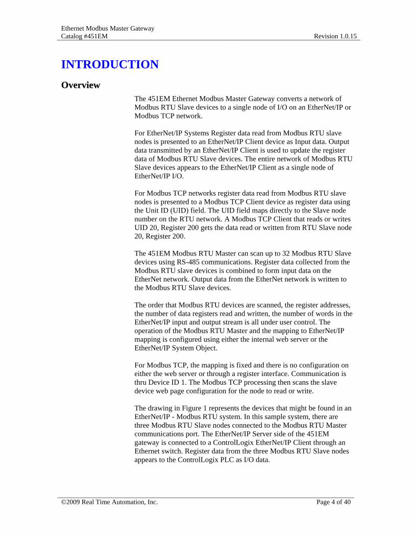
OOvveerrvviieeww The 451EM Ethernet Modbus Master Gateway converts a network of Modbus RTU Slave devices to a single node of I/O on an EtherNet/IP or Modbus TCP network. For EtherNet/IP Systems Register data read from Modbus RTU slave nodes is presented to an EtherNet/IP Client device as Input data. Output data transmitted by an EtherNet/IP Client is used to update the register data of Modbus RTU Slave devices. The entire network of Modbus RTU Slave devices appears to the EtherNet/IP Client as a single node of EtherNet/IP I/O. For Modbus TCP networks register data read from Modbus RTU slave nodes is presented to a Modbus TCP Client device as register data using the Unit ID (UID) field. The UID field maps directly to the Slave node number on the RTU network. A Modbus TCP Client that reads or writes UID 20, Register 200 gets the data read or written from RTU Slave node 20, Register 200. The 451EM Modbus RTU Master can scan up to 32 Modbus RTU Slave devices using RS-485 communications. Register data collected from the Modbus RTU slave devices is combined to form input data on the EtherNet network. Output data from the EtherNet network is written to the Modbus RTU Slave devices. The order that Modbus RTU devices are scanned, the register addresses, the number of data registers read and written, the number of words in the EtherNet/IP input and output stream is all under user control. The operation of the Modbus RTU Master and the mapping to EtherNet/IP mapping is configured using either the internal web server or the EtherNet/IP System Object. For Modbus TCP, the mapping is fixed and there is no configuration on either the web server or through a register interface. Communication is thru Device ID 1. The Modbus TCP processing then scans the slave device web page configuration for the node to read or write. The drawing in Figure 1 represents the devices that might be found in an EtherNet/IP - Modbus RTU system. In this sample system, there are three Modbus RTU Slave nodes connected to the Modbus RTU Master communications port. The EtherNet/IP Server side of the 451EM gateway is connected to a ControlLogix EtherNet/IP Client through an Ethernet switch. Register data from the three Modbus RTU Slave nodes appears to the ControlLogix PLC as I/O data.
Ethernet Modbus Master Gateway Catalog #451EM
Revision 1.0.15
©2009 Real Time Automation, Inc. Page 5 of 40
EtherNet/IP Network
EtherNet/IP Client
Up to 32 RS485 Modbus RTU Slave Devices
153.2
Figure 1 – Example EtherNet/IP Modbus TCP System
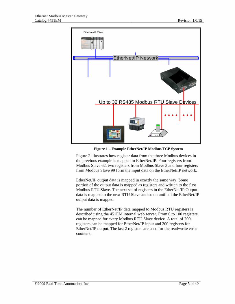
Figure 2 illustrates how register data from the three Modbus devices in the previous example is mapped to EtherNet/IP. Four registers from Modbus Slave 62, two registers from Modbus Slave 3 and four registers from Modbus Slave 99 form the input data on the EtherNet/IP network. EtherNet/IP output data is mapped in exactly the same way. Some portion of the output data is mapped as registers and written to the first Modbus RTU Slave. The next set of registers in the EtherNet/IP Output data is mapped to the next RTU Slave and so on until all the EtherNet/IP output data is mapped. The number of EtherNet/IP data mapped to Modbus RTU registers is described using the 451EM internal web server. From 0 to 100 registers can be mapped for every Modbus RTU Slave device. A total of 200 registers can be mapped for EtherNet/IP input and 200 registers for EtherNet/IP output. The last 2 registers are used for the read/write error counters.
Ethernet Modbus Master Gateway Catalog #451EM
Revision 1.0.15
©2009 Real Time Automation, Inc. Page 6 of 40
MODBUS RTU NETWORK
EtherNet/IP Network
106 22 6790 1 15 77 22 567 33 34
Input Assembly To PLC
DEVICE 2Modbus Address 62Read Address 2205
Len 4
106 22 6790 1
DEVICE 4Modbus Address 3Read Address 215
Len 2
15 77
DEVICE 6Modbus Address 99
Read Address 1Len 4
22 567 33 34
Figure 2 - EtherNet/IP Modbus TCP Gateway Data Flow
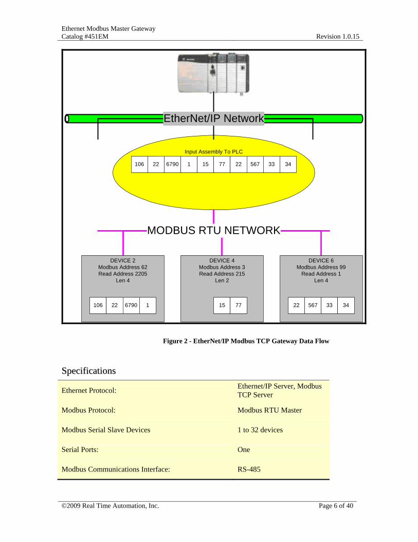
SSppeecciiffiiccaattiioonnss
Ethernet Protocol: Ethernet/IP Server, Modbus TCP Server
Modbus Protocol: Modbus RTU Master
Modbus Serial Slave Devices 1 to 32 devices
Serial Ports: One
Modbus Communications Interface: RS-485
Ethernet Modbus Master Gateway Catalog #451EM
Revision 1.0.15
©2009 Real Time Automation, Inc. Page 7 of 40
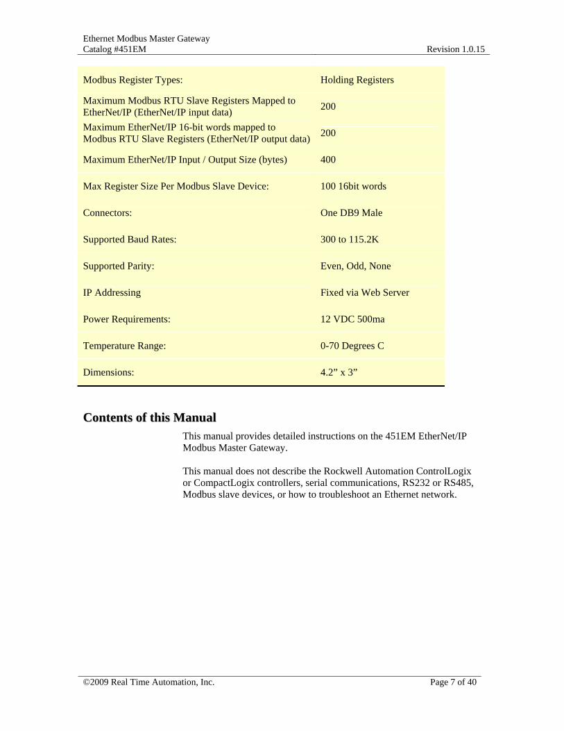
Modbus Register Types: Holding Registers
Maximum Modbus RTU Slave Registers Mapped to EtherNet/IP (EtherNet/IP input data) 200
Maximum EtherNet/IP 16-bit words mapped to Modbus RTU Slave Registers (EtherNet/IP output data) 200
Maximum EtherNet/IP Input / Output Size (bytes) 400
Max Register Size Per Modbus Slave Device: 100 16bit words
Connectors: One DB9 Male
Supported Baud Rates: 300 to 115.2K
Supported Parity: Even, Odd, None
IP Addressing Fixed via Web Server
Power Requirements: 12 VDC 500ma
Temperature Range: 0-70 Degrees C
Dimensions: 4.2” x 3”
CCoonntteennttss ooff tthhiiss MMaannuuaall This manual provides detailed instructions on the 451EM EtherNet/IP Modbus Master Gateway. This manual does not describe the Rockwell Automation ControlLogix or CompactLogix controllers, serial communications, RS232 or RS485, Modbus slave devices, or how to troubleshoot an Ethernet network.
Ethernet Modbus Master Gateway Catalog #451EM
Revision 1.0.15
©2009 Real Time Automation, Inc. Page 8 of 40
WIRING THE MODBUS RTU NETWORK
OOvveerrvviieeww Modbus Slave devices are connected to the 451EM Modbus Master Gateway using RS485 communications. Up to thirty-two Modbus Serial Slave devices can be connected to the Modbus Master. This section describes the electrical connection of the slave devices on the Modbus network.
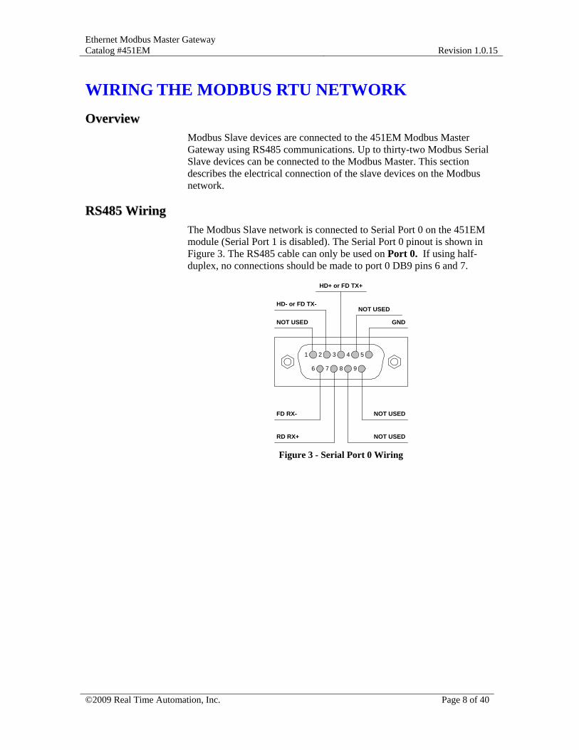
RRSS448855 WWiirriinngg The Modbus Slave network is connected to Serial Port 0 on the 451EM module (Serial Port 1 is disabled). The Serial Port 0 pinout is shown in Figure 3. The RS485 cable can only be used on Port 0. If using half-duplex, no connections should be made to port 0 DB9 pins 6 and 7.
1 2 3 4 5
6 7 8 9
NOT USED GND
NOT USEDFD RX-
RD RX+ NOT USED
HD- or FD TX-
HD+ or FD TX+
NOT USED
Figure 3 - Serial Port 0 Wiring

Ethernet Modbus Master Gateway Catalog #451EM
Revision 1.0.15
©2009 Real Time Automation, Inc. Page 9 of 40
SSeerriiaall PPoorrtt 00 JJuummppeerr CCoonnffiigguurraattiioonn Serial Port 0 can be configured for either RS232 or RS485 communications using Jumpers JP1 through JP5. These jumpers are factory set to the configuration shown in Figure 4 and should not be changed.
Figure 4 - RS485 Jumper Configuration
Ethernet Modbus Master Gateway Catalog #451EM
Revision 1.0.15
©2009 Real Time Automation, Inc. Page 10 of 40
CONFIGURING USING THE WEB SERVER
OOvveerrvviieeww The 451EM Modbus Master is configured using either the internal web server or the EtherNet/IP network. Configuration can be completed using either method. The Modbus RTU Master requires a list of Modbus Slave nodes to scan, the starting Read and Write register addresses and the Read and Write Register lengths to begin scanning. This section describes how to enable the Modbus RTU Master using the internal web server.
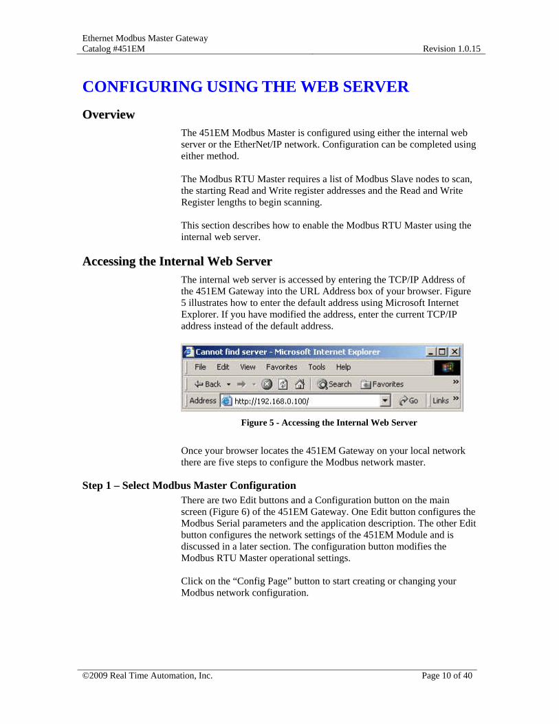
AAcccceessssiinngg tthhee IInntteerrnnaall WWeebb SSeerrvveerr The internal web server is accessed by entering the TCP/IP Address of the 451EM Gateway into the URL Address box of your browser. Figure 5 illustrates how to enter the default address using Microsoft Internet Explorer. If you have modified the address, enter the current TCP/IP address instead of the default address.
Figure 5 - Accessing the Internal Web Server
Once your browser locates the 451EM Gateway on your local network there are five steps to configure the Modbus network master.
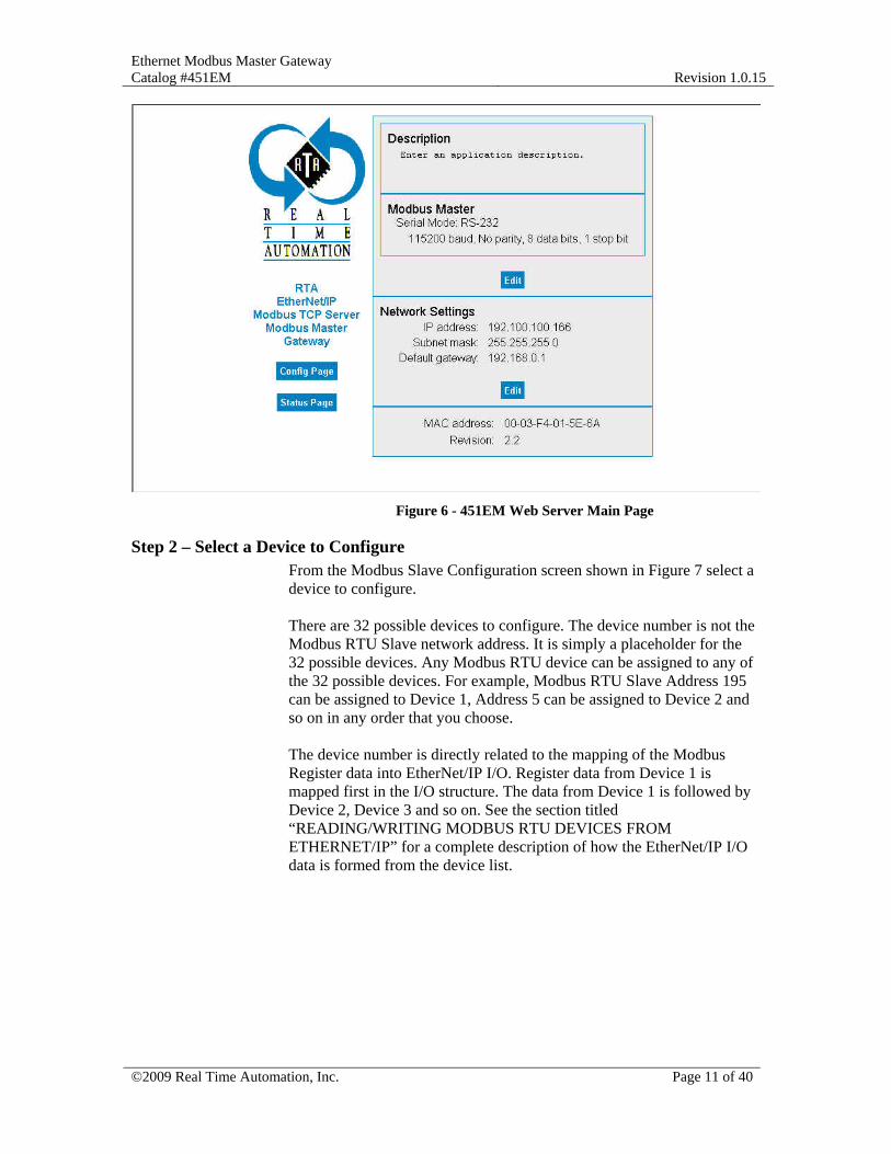
Step 1 – Select Modbus Master Configuration There are two Edit buttons and a Configuration button on the main screen (Figure 6) of the 451EM Gateway. One Edit button configures the Modbus Serial parameters and the application description. The other Edit button configures the network settings of the 451EM Module and is discussed in a later section. The configuration button modifies the Modbus RTU Master operational settings. Click on the “Config Page” button to start creating or changing your Modbus network configuration.
Ethernet Modbus Master Gateway Catalog #451EM
Revision 1.0.15
©2009 Real Time Automation, Inc. Page 11 of 40
Figure 6 - 451EM Web Server Main Page
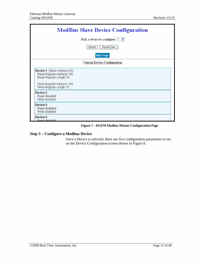
Step 2 – Select a Device to Configure From the Modbus Slave Configuration screen shown in Figure 7 select a device to configure. There are 32 possible devices to configure. The device number is not the Modbus RTU Slave network address. It is simply a placeholder for the 32 possible devices. Any Modbus RTU device can be assigned to any of the 32 possible devices. For example, Modbus RTU Slave Address 195 can be assigned to Device 1, Address 5 can be assigned to Device 2 and so on in any order that you choose. The device number is directly related to the mapping of the Modbus Register data into EtherNet/IP I/O. Register data from Device 1 is mapped first in the I/O structure. The data from Device 1 is followed by Device 2, Device 3 and so on. See the section titled “READING/WRITING MODBUS RTU DEVICES FROM ETHERNET/IP” for a complete description of how the EtherNet/IP I/O data is formed from the device list.
Ethernet Modbus Master Gateway Catalog #451EM
Revision 1.0.15
©2009 Real Time Automation, Inc. Page 12 of 40
Figure 7 - 451EM Modbus Master Configuration Page
Step 3 – Configure a Modbus Device Once a Device is selected, there are five configuration parameters to set on the Device Configuration screen shown in Figure 8.
Ethernet Modbus Master Gateway Catalog #451EM
Revision 1.0.15
©2009 Real Time Automation, Inc. Page 13 of 40
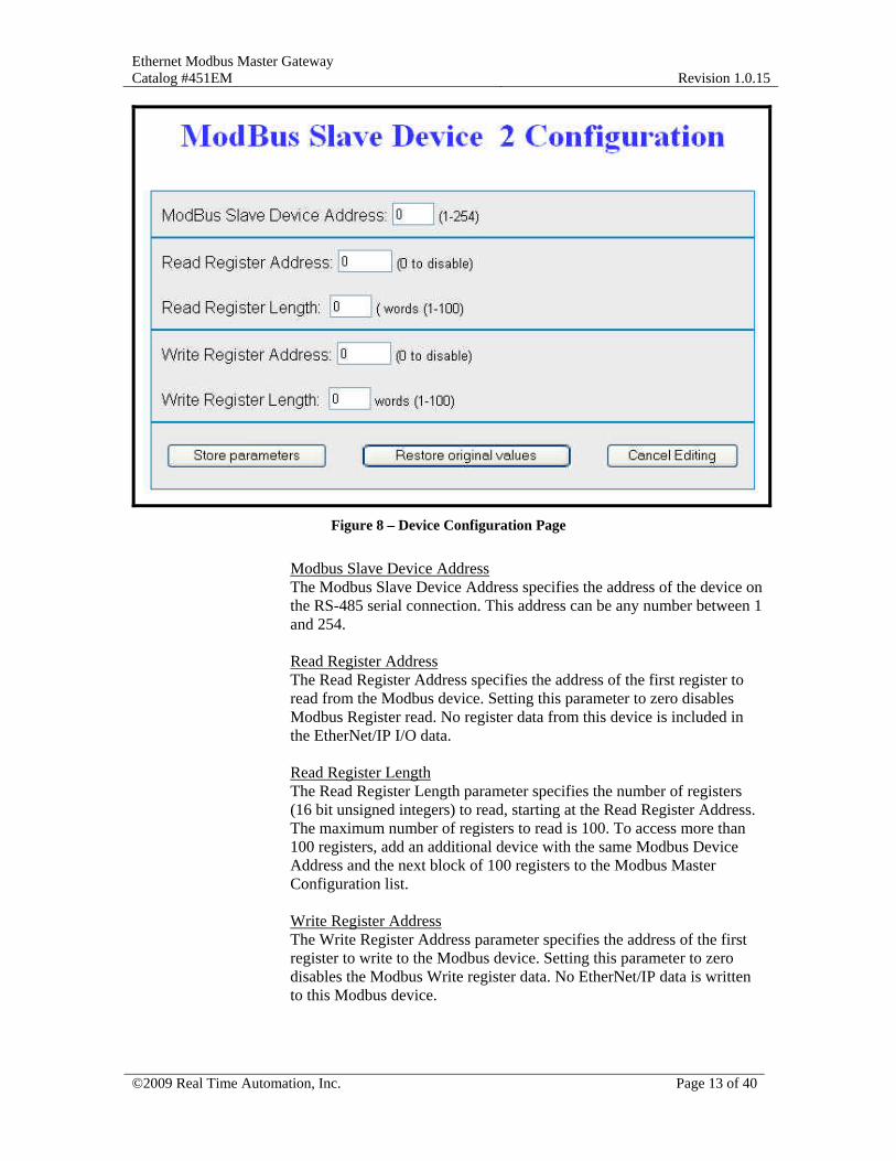
Figure 8 – Device Configuration Page
Modbus Slave Device Address The Modbus Slave Device Address specifies the address of the device on the RS-485 serial connection. This address can be any number between 1 and 254. Read Register Address The Read Register Address specifies the address of the first register to read from the Modbus device. Setting this parameter to zero disables Modbus Register read. No register data from this device is included in the EtherNet/IP I/O data. Read Register Length The Read Register Length parameter specifies the number of registers (16 bit unsigned integers) to read, starting at the Read Register Address. The maximum number of registers to read is 100. To access more than 100 registers, add an additional device with the same Modbus Device Address and the next block of 100 registers to the Modbus Master Configuration list. Write Register Address The Write Register Address parameter specifies the address of the first register to write to the Modbus device. Setting this parameter to zero disables the Modbus Write register data. No EtherNet/IP data is written to this Modbus device.
Ethernet Modbus Master Gateway Catalog #451EM
Revision 1.0.15
©2009 Real Time Automation, Inc. Page 14 of 40
Write Register Length The Write Register Length parameter specifies the number of registers (16 bit unsigned integers) to write, starting at the Write Register Address. The maximum number of registers to write is 100. If writing more than 100 registers, add an additional device table with the same Modbus Device address and the next block of 100 registers to the Modbus Master Configuration list. Once all configuration parameters for the device are specified, click on “Store Parameters” to save the device configuration and return to the main Modbus Master Configuration page.
Step 4 – Configure All Your Other Modbus Devices Using the Modbus Master main configuration page configure the remainder of your devices. When complete, hit the “Store Parameters” button to return to the main page of the web server.
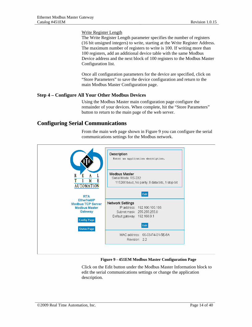
CCoonnffiigguurriinngg SSeerriiaall CCoommmmuunniiccaattiioonnss From the main web page shown in Figure 9 you can configure the serial communications settings for the Modbus network.
Figure 9 - 451EM Modbus Master Configuration Page
Click on the Edit button under the Modbus Master Information block to edit the serial communications settings or change the application description.
Ethernet Modbus Master Gateway Catalog #451EM
Revision 1.0.15
©2009 Real Time Automation, Inc. Page 15 of 40
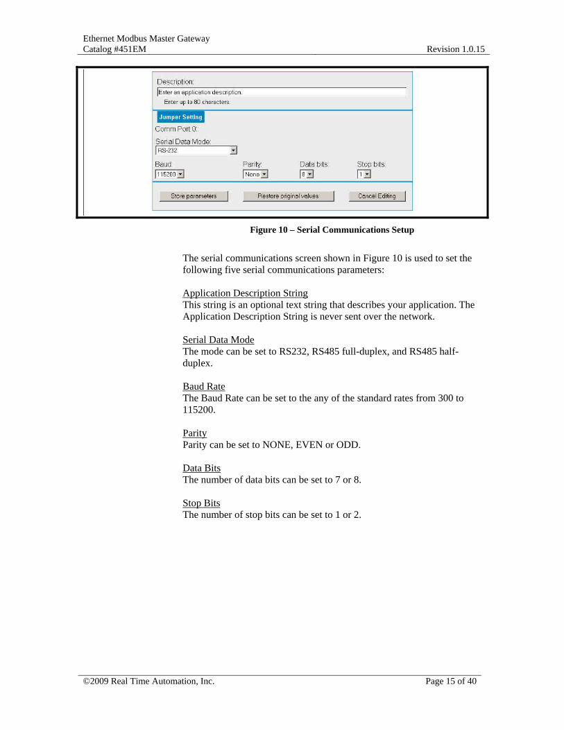
Figure 10 – Serial Communications Setup
The serial communications screen shown in Figure 10 is used to set the following five serial communications parameters: Application Description String This string is an optional text string that describes your application. The Application Description String is never sent over the network. Serial Data Mode The mode can be set to RS232, RS485 full-duplex, and RS485 half-duplex. Baud Rate The Baud Rate can be set to the any of the standard rates from 300 to 115200. Parity Parity can be set to NONE, EVEN or ODD. Data Bits The number of data bits can be set to 7 or 8. Stop Bits The number of stop bits can be set to 1 or 2.

Ethernet Modbus Master Gateway Catalog #451EM
Revision 1.0.15
©2009 Real Time Automation, Inc. Page 16 of 40
READING/WRITING MODBUS RTU DEVICES FROM ETHERNET/IP
OOvveerrvviieeww The EtherNet/IP Modbus RTU Gateway is a complete EtherNet/IP Server with all the required EtherNet/IP objects. It also includes the four vendor specific objects shown in OBJECT CLASS Description 64 Hex (100 Decimal) Gateway Write Data Object 65 Hex (101 Decimal) Gateway Read Data Object 66 Hex (102 Decimal) Gateway Serial Configuration Object 67 Hex (103 Decimal) Gateway Device Configuration Object
Figure 11 - EtherNet/IP Vendor Specific Objects
This section describes the EtherNet/IP Object Model and how to read/write the object data using EtherNet/IP Explicit and I/O messaging.
OObbjjeecctt MMooddeell The Object Model for the EtherNet/IP Modbus RTU Gateway is shown in Figure 12.
Ethernet
0x04Assembly Object
Input Instance 64 hex - Output Instance 81 Hex (empty)
0x01IdentityObject
0x02Message Router
Object
0xF6Ethernet Link
Object
0xF5TCP Object
0x66Serial Config
Object
0x67DeviceConfig Object
0x64Write Data
Object
0x06Connection Manager Object
Explicit(TCP)
I/O*(UDP)
0x65Read Data
Object
Input Assembly Instance 64Device 32
DataDevice 2
DataDevice 1
Data
0x04Assembly Object
Input Instance 64 hex - Output Instance 81 Hex (empty)Input Assembly Instance 64
Device 32Data
Device 2Data
Device 1Data
Output Assembly Instance 71Device 32
DataDevice 2
DataDevice 1
Data
Figure 12 - EtherNet/IP Modbus RTU Object Model
Ethernet Modbus Master Gateway Catalog #451EM
Revision 1.0.15
©2009 Real Time Automation, Inc. Page 17 of 40
EExxpplliicciitt MMeessssaaggiinngg EtherNet/IP Explicit Messaging Services are supported for all objects in the object model. The specific instances and attributes for each Object Class are presented in Appendix A.
AAsssseemmbbllyy OObbjjeecctt There are two optional assembly instances. Option one supports input from the Modbus RTU network to the EtherNet/IP network. Option two supports both input and output between the Modbus RTU network and the EtherNet/IP network. The input and output assemblies are described in detail in the Appendix. The gateway defaults to option 2 – input and output between the Modbus RTU network and the EtherNet/IP network.
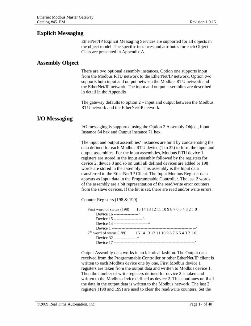
II//OO MMeessssaaggiinngg I/O messaging is supported using the Option 2 Assembly Object, Input Instance 64 hex and Output Instance 71 hex. The input and output assemblies’ instances are built by concatenating the data defined for each Modbus RTU device (1 to 32) to form the input and output assemblies. For the input assemblies, Modbus RTU device 1 registers are stored in the input assembly followed by the registers for device 2, device 3 and so on until all defined devices are added or 198 words are stored in the assembly. This assembly is the Input data transferred to the EtherNet/IP Client. The Input Modbus Register data appears as Input data in the Programmable Controller. The last 2 words of the assembly are a bit representation of the read/write error counters from the slave devices. If the bit is set, there are read and/or write errors. Counter Registers (198 & 199)
First word of status (198) 15 14 13 12 11 10 9 8 7 6 5 4 3 2 1 0
Device 16 ------------------^ Device 15 ---------------------^ Device 14 -------------------------^ Device 1 -------------------------------------------------------------^ 2nd word of status (199) 15 14 13 12 11 10 9 8 7 6 5 4 3 2 1 0 Device 32 -----------------^ Device 17 -----------------------------------------------------------^
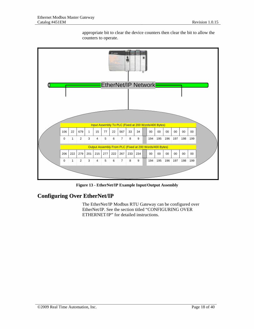
Output Assembly data works in an identical fashion. The Output data received from the Programmable Controller or other EtherNet/IP client is written to each Modbus device one by one. First Modbus device 1 registers are taken from the output data and written to Modbus device 1. Then the number of write registers defined for device 2 is taken and written to the Modbus device defined as device 2. This continues until all the data in the output data is written to the Modbus network. The last 2 registers (198 and 199) are used to clear the read/write counters. Set the
Ethernet Modbus Master Gateway Catalog #451EM
Revision 1.0.15
©2009 Real Time Automation, Inc. Page 18 of 40
appropriate bit to clear the device counters then clear the bit to allow the counters to operate.
EtherNet/IP Network
8 9 194 195 196 197 198 1990 1 2 3 4 5 6 7
Output Assembly From PLC (Fixed at 200 Words/400 Bytes)
206 222 279 201 215 277 222 267 233 234 00 00 00 00 00 00
8 9 194 195 196 197 198 1990 1 2 3 4 5 6 7
Input Assembly To PLC (Fixed at 200 Words/400 Bytes)
106 22 679 1 15 77 22 567 33 34 00 00 00 00 00 00
Figure 13 - EtherNet/IP Example Input/Output Assembly
CCoonnffiigguurriinngg OOvveerr EEtthheerrNNeett//IIPP The EtherNet/IP Modbus RTU Gateway can be configured over EtherNet/IP. See the section titled “CONFIGURING OVER ETHERNET/IP” for detailed instructions.
Ethernet Modbus Master Gateway Catalog #451EM
Revision 1.0.15
©2009 Real Time Automation, Inc. Page 19 of 40
CONFIGURING OVER ETHERNET/IP The Ethernet/IP Modbus Gateway can be configured from the internal web server or over the network. To configure the device over the EtherNet/IP network you must access the objects described in the section using EtherNet/IP Explicit Messaging. See your EtherNet/IP Network tool documentation for an explanation of Explicit Messaging. Configuration settings made using one method can be read and verified from the other method. For example, configuration settings made over EtherNet/IP can be displayed and modified using the internal web server. Configuration settings made using the internal web server can be read and revised using an EtherNet/IP network tool.
MMooddbbuuss RRTTUU NNeettwwoorrkk CCoonnffiigguurraattiioonn The configuration for each of the 32 Modbus RTU devices can be read or written over EtherNet/IP by accessing Object Class 67 hex. There are 32 instances of Object 67 hex, one for each Modbus RTU device. For each device, Explicit messages can be sent to Read or Write the Modbus configuration including the Modbus Slave Address, Read and Write Register Addresses and Read and Write Register lengths. See the complete description of Object 67 Hex in the appendix.
MMooddbbuuss RRTTUU SSeerriiaall CCoonnffiigguurraattiioonn The Modbus network baud rate, parity, number of stop bits and number of data bits can be read or written over EtherNet/IP by accessing Object Class 66 hex. There are 32 instances of Object 66. For each configuration parameter messages can be sent to Read or Write the serial configuration data. See the complete description of Object 66 Hex in the appendix.
Ethernet Modbus Master Gateway Catalog #451EM
Revision 1.0.15
©2009 Real Time Automation, Inc. Page 20 of 40
READING/WRITING MODBUS RTU DEVICES FROM MODBUS TCP
OOvveerrvviieeww The EtherNet Modbus RTU Gateway is a complete Modbus TCP Server that provides access to a Modbus RTU network. There is an internal scanlist in the gateway. Using the internal web server, the size of the read data area and write data area are stored in the gateway. For every entry in the scanlist, the gateway exchanges data with the Modbus RTU device assigned to that entry. Data from the Modbus RTU slave is transferred to the internal memory of the gateway using a Read Holding Register command. New data values in the gateway are transmitted to a Modbus RTU device from the internal data table using Write Holding Register instructions. There are 32 entries in the scanlist. The 32 entries in the scanlist can be set to 32 different Modbus RTU Slave nodes or 32 different data areas in a single Modbus slave node or any other combination. Up to 100 registers can be mapped for each entry in the scanlist. The scanlist entries are set using the internal web server.
MMooddbbuuss RRTTUU OOppeerraattiioonn On the Modbus RTU side of the gateway, the gateway is a Modbus RTU Master with a 32 device scanlist. Each entry in the scanlist is polled using Modbus Read Holding Registers and the data is stored in the gateway. Whenever new Write data is loaded from the Ethernet side of the gateway, the data is transferred to the Modbus RTU device using Write Holding Registers. No other holding registers can be written to the device except those identified in the scanlist. The Modbus RTU address, the number of registers transferred to and from the device are set using the internal Web Server.
MMooddbbuuss TTCCPP OOppeerraattiioonn On the Modbus TCP side of the gateway, the unit is a Modbus TCP Server. The TCP/IP address of the gateway is set using the internal web server. Modbus RTU devices are accessed using the Modbus TCP server using the UID (Unit ID) field of the Modbus TCP message. The Unit ID (UID) field of the Modbus TCP message identifies the specific Modbus RTU slave. The UID field must contain the Modbus RTU Address on the RTU network and a valid register address and data length for Modbus RTU.
Ethernet Modbus Master Gateway Catalog #451EM
Revision 1.0.15
©2009 Real Time Automation, Inc. Page 21 of 40
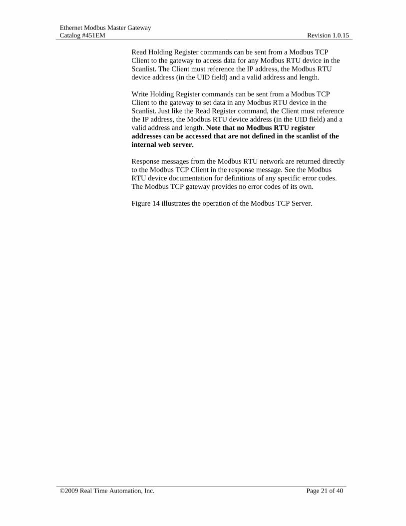
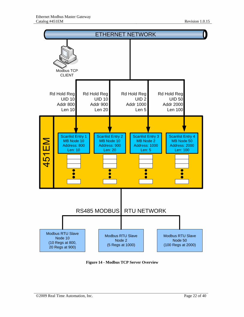
Read Holding Register commands can be sent from a Modbus TCP Client to the gateway to access data for any Modbus RTU device in the Scanlist. The Client must reference the IP address, the Modbus RTU device address (in the UID field) and a valid address and length. Write Holding Register commands can be sent from a Modbus TCP Client to the gateway to set data in any Modbus RTU device in the Scanlist. Just like the Read Register command, the Client must reference the IP address, the Modbus RTU device address (in the UID field) and a valid address and length. Note that no Modbus RTU register addresses can be accessed that are not defined in the scanlist of the internal web server. Response messages from the Modbus RTU network are returned directly to the Modbus TCP Client in the response message. See the Modbus RTU device documentation for definitions of any specific error codes. The Modbus TCP gateway provides no error codes of its own. Figure 14 illustrates the operation of the Modbus TCP Server.
Ethernet Modbus Master Gateway Catalog #451EM
Revision 1.0.15
©2009 Real Time Automation, Inc. Page 22 of 40
Modbus RTU Slave Node 10
(10 Regs at 800,20 Regs at 900)
Modbus RTU Slave Node 2
(5 Regs at 1000)
Modbus RTU Slave Node 50
(100 Regs at 2000)
Scanlist Entry 1MB Node 10Address: 800
Len: 10
Scanlist Entry 2MB Node 10Address: 900
Len: 20
Scanlist Entry 3MB Node 2
Address: 1000Len: 5
Scanlist Entry 4MB Node 50
Address: 2000Len: 100
RS485 MODBUS RTU NETWORK
ETHERNET NETWORK
`
Modbus TCPCLIENT
Rd Hold RegUID 10
Addr 800Len 10
Rd Hold RegUID 10
Addr 900Len 20
Rd Hold RegUID 2
Addr 1000Len 5
Rd Hold RegUID 50
Addr 2000Len 100
Figure 14 - Modbus TCP Server Overview

Ethernet Modbus Master Gateway Catalog #451EM
Revision 1.0.15
©2009 Real Time Automation, Inc. Page 23 of 40
CONFIGURING MODULE NETWORK SETTINGS
OOvveerrvviieeww There are three basic settings that must be configured to properly operate the 451EM Gateway. These settings are configured using the internal web server and accessed by clicking on the “Edit” button under the Network Settings section of the server main page. The Ethernet Network Settings are configured from the Network Edit Screen shown in Figure 15.
Figure 15 - Module Network Settings Edit Page
The three configuration parameters are:
IP Address The IP Address is the TCP/IP address of the 451EM module. This address normally exists on the same subnet as the EtherNet/IP device.
Subnet Mask The Subnet Mask is the address mask for the current subnet.
Default Gateway The Default Gateway is the address of the device which serves as the gateway for non-local TCP/IP addresses. The default gateway TCP/IP address is usually the address of a router.

Ethernet Modbus Master Gateway Catalog #451EM
Revision 1.0.15
©2009 Real Time Automation, Inc. Page 24 of 40
The default settings for the module network entries are:
CONFIGURATION PARAMETER DEFAULT VALUE
IP Address: 192.168.0.100
Subnet Mask: 255.255.255.0
Default Gateway Address: 192.168.0.1
Figure 16 - Default Network Settings

Ethernet Modbus Master Gateway Catalog #451EM
Revision 1.0.15
©2009 Real Time Automation, Inc. Page 25 of 40
DIAGNOSTICS & TROUBLESHOOTING A Status page is accessible from the main page of the internal web server. The Status page indicates the status of communications on the Modbus RTU network. The status page is accessed by clicking on the button labeled “Status Page” on the main page of the internal web server. A sample status page is shown in Figure 17.
Figure 17 - Modbus RTU Network Status Page
Status information is presented for each of the 32 possible devices on the Modbus network. The Modbus RTU Slave Address, Read Status and Write Status are listed for each device. If a Read Operation or Write Operation is not defined for a device, the operation is listed as disabled.
Ethernet Modbus Master Gateway Catalog #451EM
Revision 1.0.15
©2009 Real Time Automation, Inc. Page 26 of 40
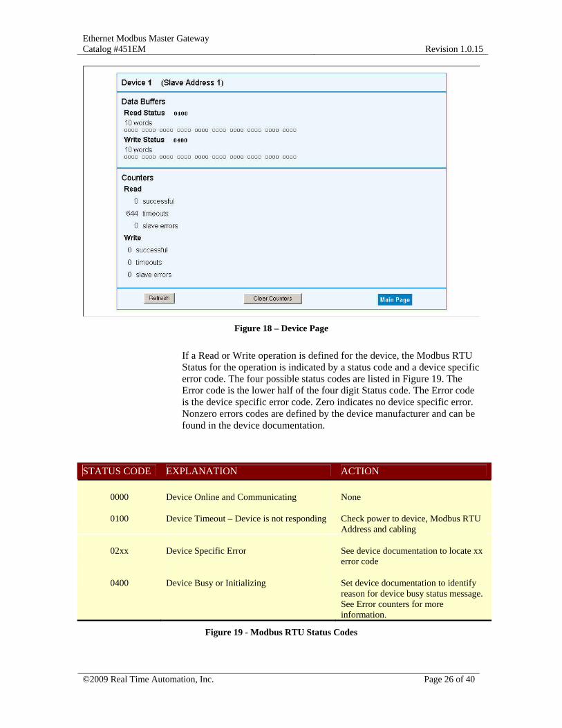
Figure 18 – Device Page
If a Read or Write operation is defined for the device, the Modbus RTU Status for the operation is indicated by a status code and a device specific error code. The four possible status codes are listed in Figure 19. The Error code is the lower half of the four digit Status code. The Error code is the device specific error code. Zero indicates no device specific error. Nonzero errors codes are defined by the device manufacturer and can be found in the device documentation.
STATUS CODE EXPLANATION ACTION
0000 Device Online and Communicating None
0100 Device Timeout – Device is not responding Check power to device, Modbus RTU Address and cabling
02xx Device Specific Error See device documentation to locate xx error code
0400 Device Busy or Initializing Set device documentation to identify reason for device busy status message. See Error counters for more information.
Figure 19 - Modbus RTU Status Codes
Ethernet Modbus Master Gateway Catalog #451EM
Revision 1.0.15
©2009 Real Time Automation, Inc. Page 27 of 40
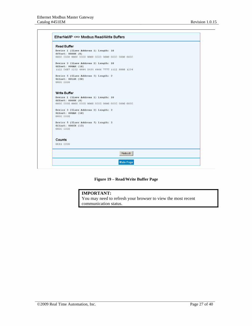
Figure 19 – Read/Write Buffer Page
IMPORTANT: You may need to refresh your browser to view the most recent communication status.

Ethernet Modbus Master Gateway Catalog #451EM
Revision 1.0.15
©2009 Real Time Automation, Inc. Page 28 of 40
Revision History
Date Name Revision Description 09/02/2005 JHM 1.0.1 Initial Revision 11/29/2005 JHM 1.3 Updated figures and added counter information
Ethernet Modbus Master Gateway Catalog #451EM
Revision 1.0.15
©2009 Real Time Automation, Inc. Page 29 of 40
APPENDIX A – EtherNet/IP Object Model
DDeevviiccee OObbjjeecctt MMooddeell The Device Object Model is the logical organization of attributes (parameters), classes (objects) and services supported by a device. Objects are composed of attributes and services. There are three types of objects in any CIP device: Required Objects, Application Objects and Vendor Specific Objects. Required Objects are object classes that must be supported by all devices on EtherNet/IP. Applications Objects are classes that must be supported by all devices using the same profile. An example of a profile is a Discrete I/O device or an AC Drive. This ensures that devices from different vendors but with the same profile have a common interface to EtherNet/IP Client devices. For example, every AC Drive device must have a motor object among its required application objects. The attribute numbers for the maximum motor frequency and other motor data are predefined by the AC Drive profile to simply access to any device supporting the AC Drive profile. Vendor Specific Objects are classes that add attributes and services that don’t fit into the Required or Application Objects. The default object representation for End User systems using the RTA Gateway for EtherNet/IP access supports 6 Required Objects and 4 Vendor Specific Objects: Required Objects (defined by EtherNet/IP Specification) • Identity Object (0x01) • Message Router Object (0x02) • Assembly Object (0x04) • Connection Manager Object (0x06) • TCP Object (0xF5) • Ethernet Link Object (0xF6) Vendor Specific Objects (defined by RTA to support End User system operation) • Gateway Write Data Object (0x64) • Gateway Read Data Object (0x65) • Gateway Serial Configuration Object (0x66) • Gateway Device Configuration Object (0x67)
Ethernet Modbus Master Gateway Catalog #451EM
Revision 1.0.15
©2009 Real Time Automation, Inc. Page 30 of 40
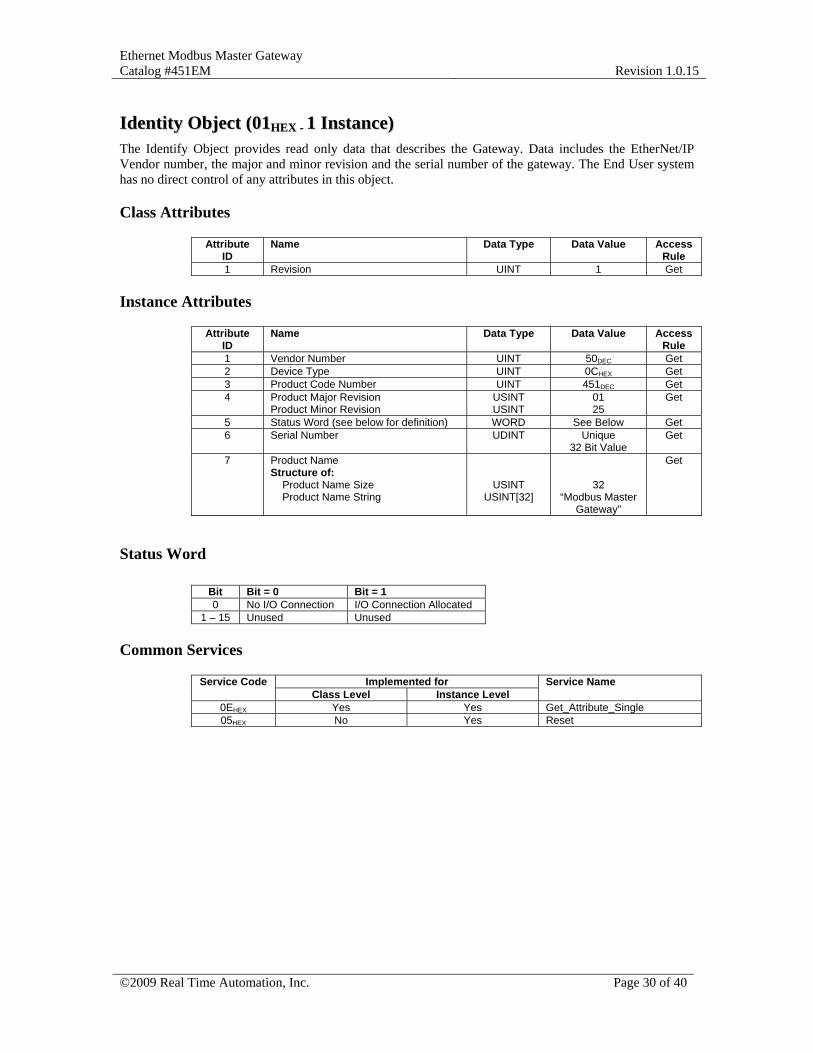
IIddeennttiittyy OObbjjeecctt ((0011HHEEXX -- 11 IInnssttaannccee)) The Identify Object provides read only data that describes the Gateway. Data includes the EtherNet/IP Vendor number, the major and minor revision and the serial number of the gateway. The End User system has no direct control of any attributes in this object.
Class Attributes
Attribute ID
Name Data Type Data Value Access Rule
1 Revision UINT 1 Get
Instance Attributes
Attribute ID
Name Data Type Data Value Access Rule
1 Vendor Number UINT 50DEC Get 2 Device Type UINT 0CHEX Get 3 Product Code Number UINT 451DEC Get 4 Product Major Revision
Product Minor Revision USINT USINT
01 25
Get
5 Status Word (see below for definition) WORD See Below Get 6 Serial Number UDINT Unique
32 Bit Value Get
7 Product Name Structure of: Product Name Size Product Name String
USINT USINT[32]
32 “Modbus Master
Gateway”
Get
Status Word
Bit Bit = 0 Bit = 1 0 No I/O Connection I/O Connection Allocated
1 – 15 Unused Unused
Common Services
Implemented for Service Code Class Level Instance Level
Service Name
0EHEX Yes Yes Get_Attribute_Single 05HEX No Yes Reset

Ethernet Modbus Master Gateway Catalog #451EM
Revision 1.0.15
©2009 Real Time Automation, Inc. Page 31 of 40
MMeessssaaggee RRoouutteerr OObbjjeecctt ((0022HHEEXX))
This object has no supported attributes.
Ethernet Modbus Master Gateway Catalog #451EM
Revision 1.0.15
©2009 Real Time Automation, Inc. Page 32 of 40
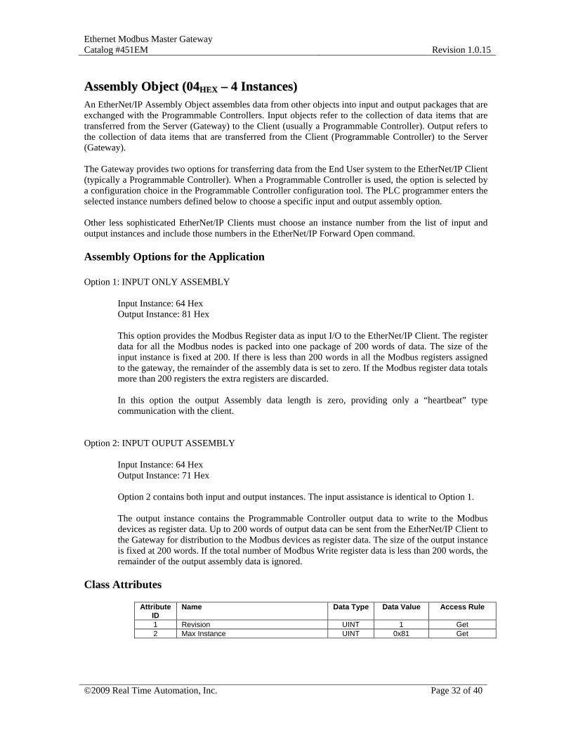
AAsssseemmbbllyy OObbjjeecctt ((0044HHEEXX –– 44 IInnssttaanncceess)) An EtherNet/IP Assembly Object assembles data from other objects into input and output packages that are exchanged with the Programmable Controllers. Input objects refer to the collection of data items that are transferred from the Server (Gateway) to the Client (usually a Programmable Controller). Output refers to the collection of data items that are transferred from the Client (Programmable Controller) to the Server (Gateway). The Gateway provides two options for transferring data from the End User system to the EtherNet/IP Client (typically a Programmable Controller). When a Programmable Controller is used, the option is selected by a configuration choice in the Programmable Controller configuration tool. The PLC programmer enters the selected instance numbers defined below to choose a specific input and output assembly option. Other less sophisticated EtherNet/IP Clients must choose an instance number from the list of input and output instances and include those numbers in the EtherNet/IP Forward Open command.
Assembly Options for the Application Option 1: INPUT ONLY ASSEMBLY
Input Instance: 64 Hex Output Instance: 81 Hex This option provides the Modbus Register data as input I/O to the EtherNet/IP Client. The register data for all the Modbus nodes is packed into one package of 200 words of data. The size of the input instance is fixed at 200. If there is less than 200 words in all the Modbus registers assigned to the gateway, the remainder of the assembly data is set to zero. If the Modbus register data totals more than 200 registers the extra registers are discarded. In this option the output Assembly data length is zero, providing only a “heartbeat” type communication with the client.
Option 2: INPUT OUPUT ASSEMBLY
Input Instance: 64 Hex Output Instance: 71 Hex Option 2 contains both input and output instances. The input assistance is identical to Option 1. The output instance contains the Programmable Controller output data to write to the Modbus devices as register data. Up to 200 words of output data can be sent from the EtherNet/IP Client to the Gateway for distribution to the Modbus devices as register data. The size of the output instance is fixed at 200 words. If the total number of Modbus Write register data is less than 200 words, the remainder of the output assembly data is ignored.
Class Attributes
Attribute ID
Name Data Type Data Value Access Rule
1 Revision UINT 1 Get 2 Max Instance UINT 0x81 Get
Ethernet Modbus Master Gateway Catalog #451EM
Revision 1.0.15
©2009 Real Time Automation, Inc. Page 33 of 40
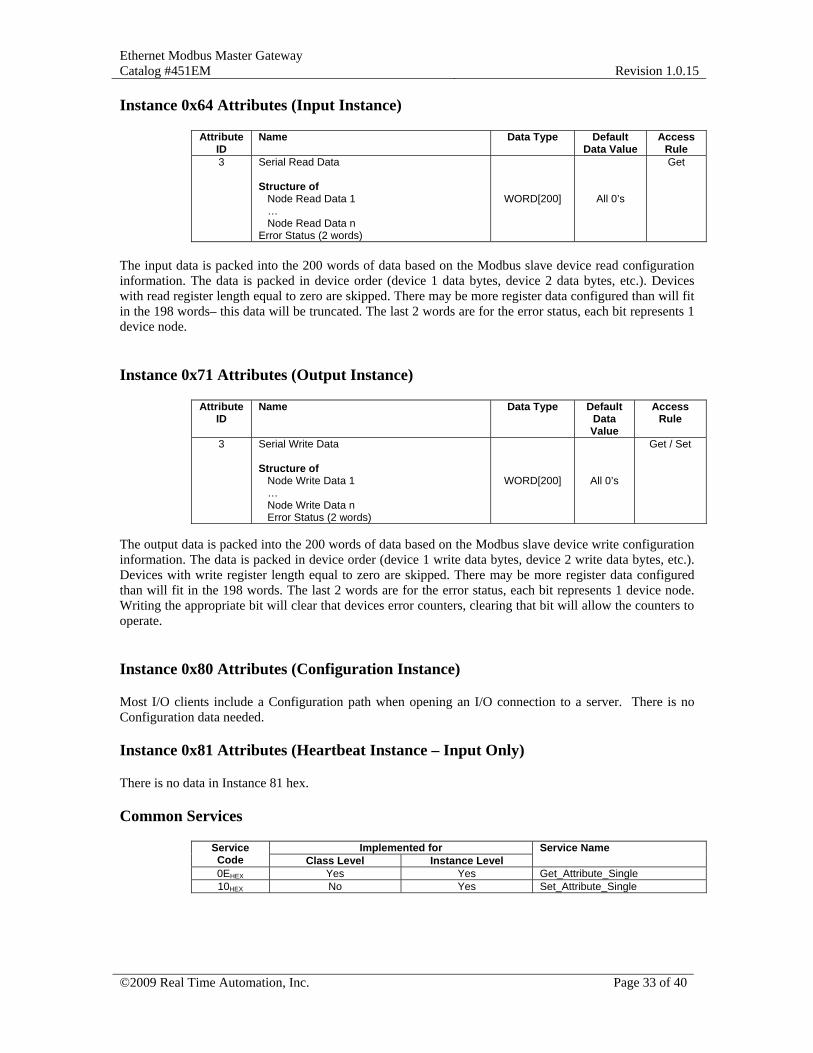
Instance 0x64 Attributes (Input Instance)
Attribute ID
Name Data Type Default Data Value
Access Rule
3 Serial Read Data Structure of Node Read Data 1 … Node Read Data n Error Status (2 words)
WORD[200]
All 0’s
Get
The input data is packed into the 200 words of data based on the Modbus slave device read configuration information. The data is packed in device order (device 1 data bytes, device 2 data bytes, etc.). Devices with read register length equal to zero are skipped. There may be more register data configured than will fit in the 198 words– this data will be truncated. The last 2 words are for the error status, each bit represents 1 device node.
Instance 0x71 Attributes (Output Instance)
Attribute ID
Name Data Type Default Data Value
Access Rule
3 Serial Write Data Structure of Node Write Data 1 … Node Write Data n Error Status (2 words)
WORD[200]
All 0’s
Get / Set
The output data is packed into the 200 words of data based on the Modbus slave device write configuration information. The data is packed in device order (device 1 write data bytes, device 2 write data bytes, etc.). Devices with write register length equal to zero are skipped. There may be more register data configured than will fit in the 198 words. The last 2 words are for the error status, each bit represents 1 device node. Writing the appropriate bit will clear that devices error counters, clearing that bit will allow the counters to operate.
Instance 0x80 Attributes (Configuration Instance)
Most I/O clients include a Configuration path when opening an I/O connection to a server. There is no Configuration data needed.
Instance 0x81 Attributes (Heartbeat Instance – Input Only) There is no data in Instance 81 hex.
Common Services
Implemented for Service Code Class Level Instance Level
Service Name
0EHEX Yes Yes Get_Attribute_Single 10HEX No Yes Set_Attribute_Single

Ethernet Modbus Master Gateway Catalog #451EM
Revision 1.0.15
©2009 Real Time Automation, Inc. Page 34 of 40
CCoonnnneeccttiioonn MMaannaaggeerr OObbjjeecctt ((0066HHEEXX))
This object has no attributes.
Ethernet Modbus Master Gateway Catalog #451EM
Revision 1.0.15
©2009 Real Time Automation, Inc. Page 35 of 40
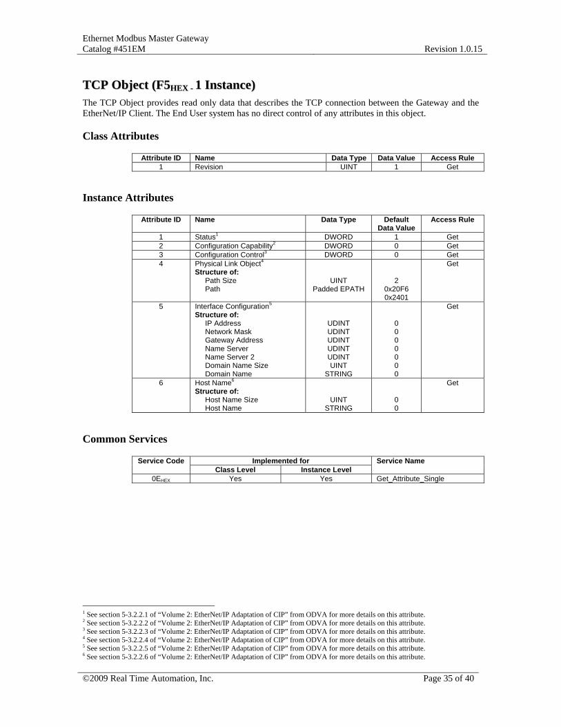
TTCCPP OObbjjeecctt ((FF55HHEEXX -- 11 IInnssttaannccee)) The TCP Object provides read only data that describes the TCP connection between the Gateway and the EtherNet/IP Client. The End User system has no direct control of any attributes in this object.
Class Attributes
Attribute ID Name Data Type Data Value Access Rule 1 Revision UINT 1 Get
Instance Attributes
Attribute ID Name Data Type Default Data Value
Access Rule
1 Status1 DWORD 1 Get 2 Configuration Capability2 DWORD 0 Get 3 Configuration Control3 DWORD 0 Get 4 Physical Link Object4
Structure of: Path Size Path
UINT Padded EPATH
2 0x20F6 0x2401
Get
5 Interface Configuration5 Structure of: IP Address Network Mask Gateway Address Name Server Name Server 2 Domain Name Size Domain Name
UDINT UDINT UDINT UDINT UDINT UINT
STRING
0 0 0 0 0 0 0
Get
6 Host Name6 Structure of: Host Name Size Host Name
UINT STRING
0 0
Get
Common Services
Implemented for Service Code Class Level Instance Level
Service Name
0EHEX Yes Yes Get_Attribute_Single
1 See section 5-3.2.2.1 of “Volume 2: EtherNet/IP Adaptation of CIP” from ODVA for more details on this attribute. 2 See section 5-3.2.2.2 of “Volume 2: EtherNet/IP Adaptation of CIP” from ODVA for more details on this attribute. 3 See section 5-3.2.2.3 of “Volume 2: EtherNet/IP Adaptation of CIP” from ODVA for more details on this attribute. 4 See section 5-3.2.2.4 of “Volume 2: EtherNet/IP Adaptation of CIP” from ODVA for more details on this attribute. 5 See section 5-3.2.2.5 of “Volume 2: EtherNet/IP Adaptation of CIP” from ODVA for more details on this attribute. 6 See section 5-3.2.2.6 of “Volume 2: EtherNet/IP Adaptation of CIP” from ODVA for more details on this attribute.
Ethernet Modbus Master Gateway Catalog #451EM
Revision 1.0.15
©2009 Real Time Automation, Inc. Page 36 of 40
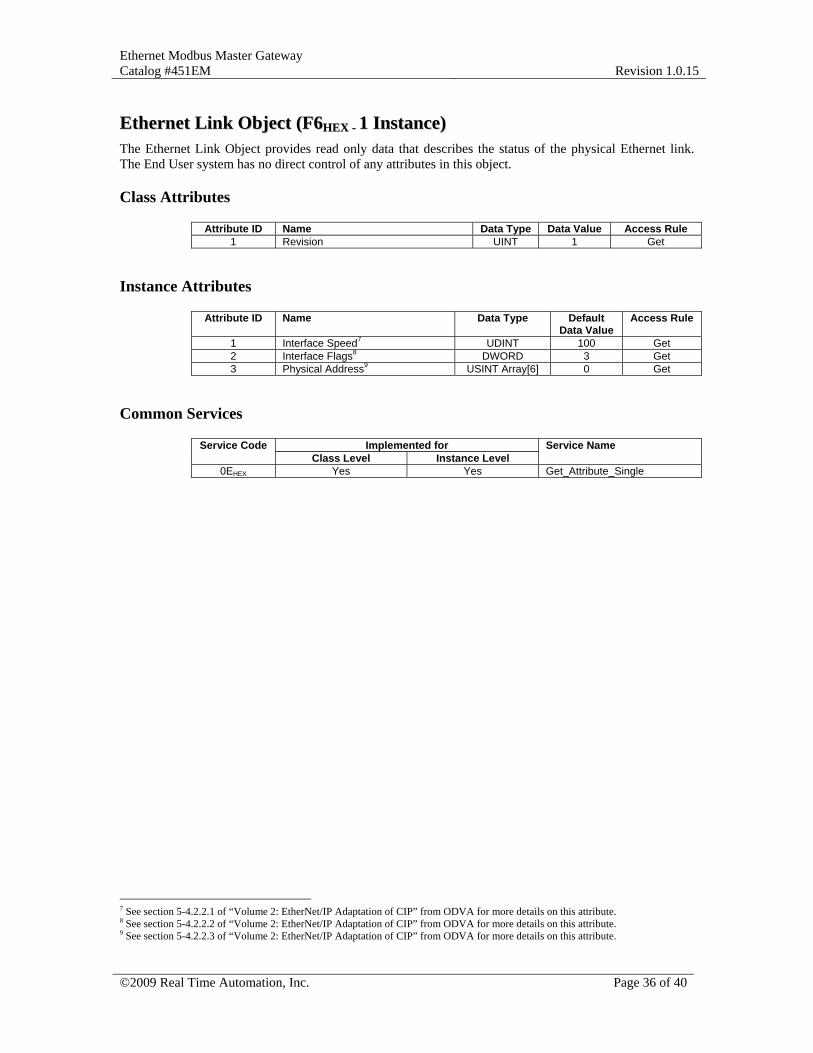
EEtthheerrnneett LLiinnkk OObbjjeecctt ((FF66HHEEXX -- 11 IInnssttaannccee)) The Ethernet Link Object provides read only data that describes the status of the physical Ethernet link. The End User system has no direct control of any attributes in this object.
Class Attributes
Attribute ID Name Data Type Data Value Access Rule 1 Revision UINT 1 Get
Instance Attributes
Attribute ID Name Data Type Default Data Value
Access Rule
1 Interface Speed7 UDINT 100 Get 2 Interface Flags8 DWORD 3 Get 3 Physical Address9 USINT Array[6] 0 Get
Common Services
Implemented for Service Code Class Level Instance Level
Service Name
0EHEX Yes Yes Get_Attribute_Single
7 See section 5-4.2.2.1 of “Volume 2: EtherNet/IP Adaptation of CIP” from ODVA for more details on this attribute. 8 See section 5-4.2.2.2 of “Volume 2: EtherNet/IP Adaptation of CIP” from ODVA for more details on this attribute. 9 See section 5-4.2.2.3 of “Volume 2: EtherNet/IP Adaptation of CIP” from ODVA for more details on this attribute.

Ethernet Modbus Master Gateway Catalog #451EM
Revision 1.0.15
©2009 Real Time Automation, Inc. Page 37 of 40
GGaatteewwaayy WWrriittee DDaattaa OObbjjeecctt ((6644HHEEXX –– 3322 IInnssttaanncceess)) The Gateway Write Data Object maps the data transferred from the EtherNet/IP to the End User system over the Modbus Master interface.
Class Attributes (Instance 0) The Write Object Class Attributes provide read only data that describes the number of words per attribute, and number of attributes per instance. The End User system has no direct control of any attributes in this object.
Attribute ID
Name Data Type
Default Data Value
Access Rule
1 Revision UINT 1 Get 2 Maximum Write Data Buffer Size (in words) UINT 100 Get 3 Number of Words per Attribute UINT 100 Get 4 Number of Data Attributes per Instance
(doesn’t include the Write Data Size attribute) UINT 1 Get
Instance Attributes (Instances 1-32) The Write Object Instance Attributes provides read/write data that contains the data transferred from an EtherNet/IP Client. Each instance of the Write Data Object maps to a node number accessible by the End User system. The thirty two write instances map to device nodes 1 to 32 of the Gateway which are mapped to the End User system Modbus interface via the Configuration Object and/or the Gateway web page setup.
Attribute ID
Name Data Type Default Data Value
Access Rule
1 Write Data Size (in words) UINT 0 Get / Set 2 Write Data [0-99] WORD[100] 0 Get / Set
Common Services
Implemented for Service Code Class Level Instance Level
Service Name
0EHEX Yes Yes Get Attribute Single 10HEX No Yes Set Attribute Single

Ethernet Modbus Master Gateway Catalog #451EM
Revision 1.0.15
©2009 Real Time Automation, Inc. Page 38 of 40
GGaatteewwaayy RReeaadd DDaattaa OObbjjeecctt ((6655HHEEXX –– 3322 IInnssttaanncceess)) The Gateway Read Data Object maps the data transferred from the End User system to an EtherNet/IP Client over the Modbus Master register interface.
Class Attributes (Instance 0) The Read Object Class Attributes provide read only data that describes the number of words per attribute and the number of attributes per instance. The End User system has no direct control of any attributes in this object.
Attribute ID
Name Data Type
Default Data Value
Access Rule
1 Revision UINT 1 Get 2 Maximum Read Data Buffer Size (in words) UINT 100 Get 3 Number of Words per Attribute UINT 100 Get 4 Number of Data Attributes per Instance
(doesn’t include the Read Data Size attribute) UINT 1 Get
Instance Attributes (Instances 1-32) The Read Object Instance Attributes provides read/write data that describes contains the data to transfer to an EtherNet/IP Client. Each instance of the Read Data Object maps to a node number accessible by the End User system. The thirty two read instances map to device nodes 1 to 32 of the Gateway which are mapped to the End User system Modbus interface via the Configuration Object and/or the Gateway web page setup
Attribute ID
Name Data Type Default Data Value
Access Rule
1 Read Data Size (in words) (ONLY writes of “0” are allowed to this attribute)
UINT 0 Get / Set
2 Read Data [0-99] WORD[100] 0 Get
Common Services
Implemented for Service Code Class Level Instance Level
Service Name
0EHEX Yes Yes Get Attribute Single 10HEX No Yes Set Attribute Single
Ethernet Modbus Master Gateway Catalog #451EM
Revision 1.0.15
©2009 Real Time Automation, Inc. Page 39 of 40
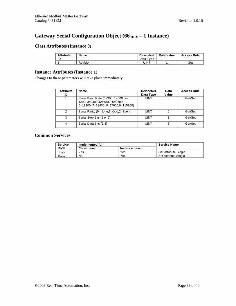
GGaatteewwaayy SSeerriiaall CCoonnffiigguurraattiioonn OObbjjeecctt ((6666 HHEEXX –– 11 IInnssttaannccee))
Class Attributes (Instance 0)
Attribute ID
Name DeviceNet Data Type
Data Value
Access Rule
1 Revision UINT 1 Get
Instance Attributes (Instance 1) Changes to these parameters will take place immediately.
Attribute ID
Name DeviceNet Data Type
Data Value
Access Rule
1 Serial Baud Rate (0=300, 1=600, 2= 1200, 3=2400,42=4800, 5=9600, 6=19200, 7=38400, 8=57600,9=115200)
UINT 6 Get/Set
2 Serial Parity (0=None,1=Odd,2=Even) UINT 0 Get/Set
3 Serial Stop Bits (1 or 2) UINT 1 Get/Set
4 Serial Data Bits (5-8) UINT 8 Get/Set
Common Services
Implemented for Service Code Class Level Instance Level
Service Name
0EHEX Yes Yes Get Attribute Single 10HEX No Yes Set Attribute Single
Ethernet Modbus Master Gateway Catalog #451EM
Revision 1.0.15
©2009 Real Time Automation, Inc. Page 40 of 40
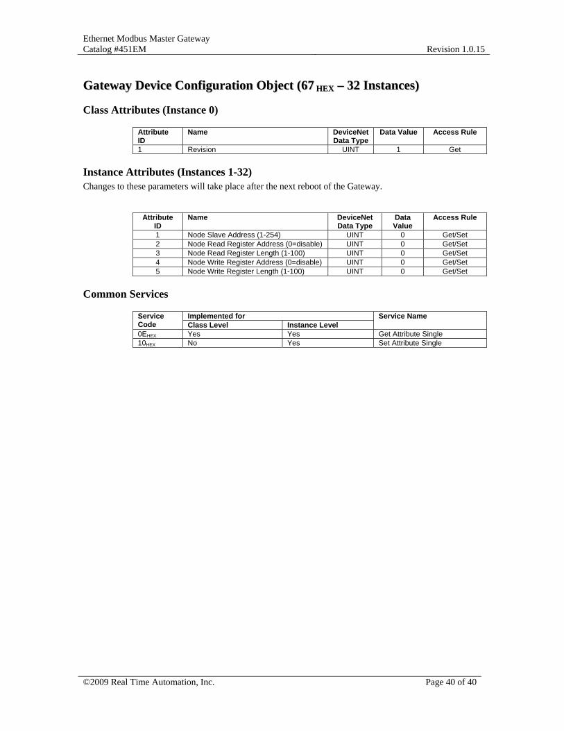
GGaatteewwaayy DDeevviiccee CCoonnffiigguurraattiioonn OObbjjeecctt ((6677 HHEEXX –– 3322 IInnssttaanncceess))
Class Attributes (Instance 0)
Attribute ID
Name DeviceNet Data Type
Data Value
Access Rule
1 Revision UINT 1 Get
Instance Attributes (Instances 1-32) Changes to these parameters will take place after the next reboot of the Gateway.
Attribute ID
Name DeviceNet Data Type
Data Value
Access Rule
1 Node Slave Address (1-254) UINT 0 Get/Set 2 Node Read Register Address (0=disable) UINT 0 Get/Set 3 Node Read Register Length (1-100) UINT 0 Get/Set 4 Node Write Register Address (0=disable) UINT 0 Get/Set 5 Node Write Register Length (1-100) UINT 0 Get/Set
Common Services
Implemented for Service Code Class Level Instance Level
Service Name
0EHEX Yes Yes Get Attribute Single 10HEX No Yes Set Attribute Single