Embed Size (px)
Citation preview
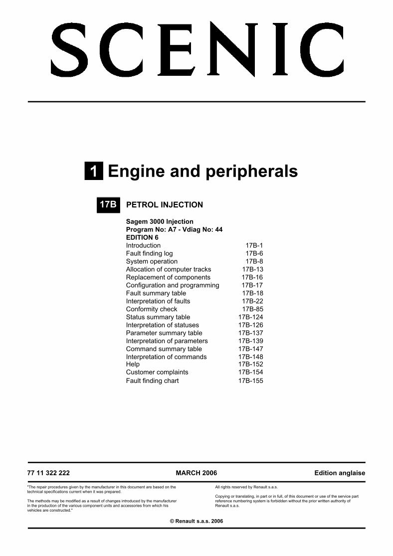
Engine and peripherals
77 11 322 222
"The repair procedures given by the manufacturer in this document are based on the technical specifications current when it was prepared.
The methods may be modified as a result of changes introduced by the manufacturer in the production of the various component units and accessories from which his vehicles are constructed."
MARCH 2006
All rights reserved by Renault s.a.s.
Edition anglaise
Copying or translating, in part or in full, of this document or use of the service part reference numbering system is forbidden without the prior written authority of Renault s.a.s.
© Renault s.a.s. 2006
PETROL INJECTION
Sagem 3000 InjectionProgram No: A7 - Vdiag No: 44EDITION 6Introduction 17B-1Fault finding log 17B-6System operation 17B-8Allocation of computer tracks 17B-13Replacement of components 17B-16Configuration and programming 17B-17Fault summary table 17B-18Interpretation of faults 17B-22Conformity check 17B-85Status summary table 17B-124Interpretation of statuses 17B-126Parameter summary table 17B-137Interpretation of parameters 17B-139Command summary table 17B-147Interpretation of commands 17B-148Help 17B-152Customer complaints 17B-154Fault finding chart 17B-155
17B
PETROL INJECTIONFault finding - Introduction 17B
117BSAGEM 3000
Program No.: A7Vdiag No.: 44
PETROL INJECTIONFault finding - Introduction
JSAA741.0
Edition 617B-1
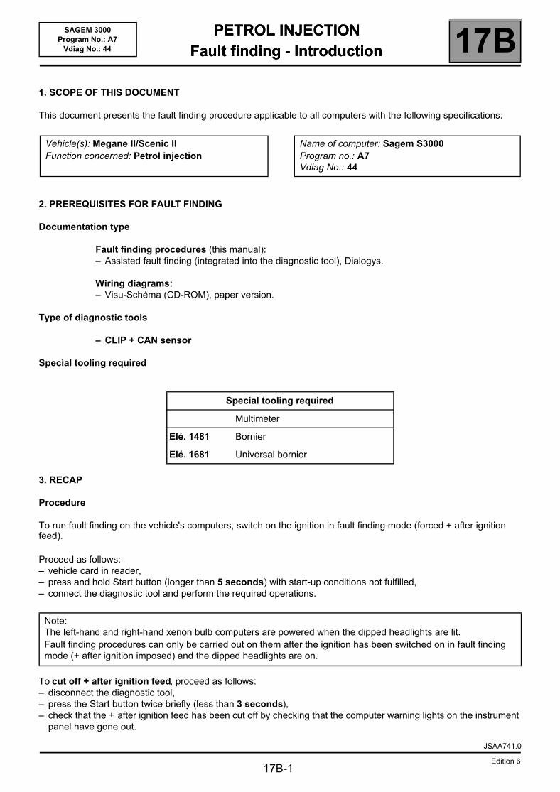
1. SCOPE OF THIS DOCUMENT
This document presents the fault finding procedure applicable to all computers with the following specifications:
2. PREREQUISITES FOR FAULT FINDING
Documentation type
Fault finding procedures (this manual):– Assisted fault finding (integrated into the diagnostic tool), Dialogys.
Wiring diagrams:– Visu-Schéma (CD-ROM), paper version.
Type of diagnostic tools
– CLIP + CAN sensor
Special tooling required
3. RECAP
Procedure
To run fault finding on the vehicle's computers, switch on the ignition in fault finding mode (forced + after ignition feed).
Proceed as follows:– vehicle card in reader,– press and hold Start button (longer than 5 seconds) with start-up conditions not fulfilled,– connect the diagnostic tool and perform the required operations.
To cut off + after ignition feed, proceed as follows:– disconnect the diagnostic tool,– press the Start button twice briefly (less than 3 seconds),– check that the + after ignition feed has been cut off by checking that the computer warning lights on the instrument
panel have gone out.
Vehicle(s): Megane II/Scenic IIFunction concerned: Petrol injection
Name of computer: Sagem S3000Program no.: A7Vdiag No.: 44
Special tooling required
Multimeter
Elé. 1481 Bornier
Elé. 1681 Universal bornier
Note:The left-hand and right-hand xenon bulb computers are powered when the dipped headlights are lit.Fault finding procedures can only be carried out on them after the ignition has been switched on in fault finding mode (+ after ignition imposed) and the dipped headlights are on.
PETROL INJECTIONFault finding - Introduction 17B
17B-2
SAGEM 3000Program No.: A7
Vdiag No.: 44
Faults
Faults are declared as either present or stored (depending on whether they appeared in a certain context and have disappeared since, or whether they remain present but have not been diagnosed within the current context).
The present or stored status of faults should be taken into consideration when the diagnostic tool is switched on after the + after ignition feed (without any system components being active).
For a present fault, apply the procedure described in the Interpretation of faults section.
For a stored fault, note the faults displayed and apply the instructions in the Notes section.
If the fault is confirmed when the instructions in the Notes section are applied, the fault is present. Deal with the fault
If the fault is not confirmed, check:– the electrical lines which correspond to the fault,– the connectors for these lines (for oxidation, bent pins, etc.),– the resistance of the component detected as faulty,– the condition of the wires (melted or split insulation, wear).
Conformity check
The aim of the conformity check is to check statuses and parameters that do not produce a fault display on the diagnostic tool when they are inconsistent. Therefore, this stage is used to:– carry out fault finding on faults that do not have a fault display, and which may correspond to a customer complaint.– check that the system is operating correctly and that there is no risk of a fault recurring after repairs.
This section gives the fault finding procedures for statuses and parameters and the conditions for checking them.
If a status is not behaving normally or a parameter is outside the permitted tolerance values, consult the corresponding fault finding page.
Customer complaints - Fault finding chart
If the test with the diagnostic tool is OK but the customer complaint is still present, the fault should be treated by customer complaints.
A summary of the overall procedure to follow is provided on the following page in the form of a flow chart.
JSAA741.0
Edition 6
PETROL INJECTIONFault finding - Introduction 17B
17B-3
SAGEM 3000Program No.: A7
Vdiag No.: 44
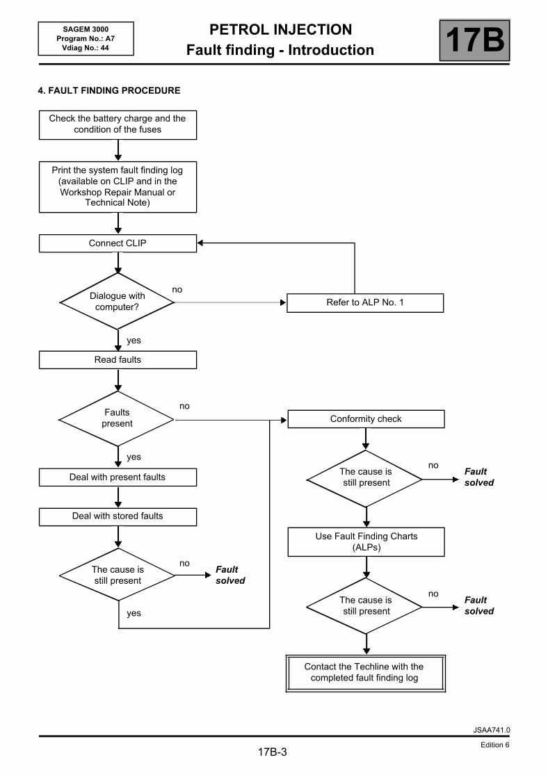
4. FAULT FINDING PROCEDURE
Check the battery charge and the condition of the fuses
Print the system fault finding log (available on CLIP and in the Workshop Repair Manual or
Technical Note)
Connect CLIP
noDialogue with
computer?
yes
Read faults
noFaults
present
yes
Deal with present faults
Deal with stored faults
noThe cause is still present
Fault solved
yes
Refer to ALP No. 1
Conformity check
noThe cause is still present
Fault solved
Use Fault Finding Charts (ALPs)
noThe cause is still present
Fault solved
Contact the Techline with the completed fault finding log
JSAA741.0
Edition 6
PETROL INJECTIONFault finding - Introduction 17B
17B-4
SAGEM 3000Program No.: A7
Vdiag No.: 44
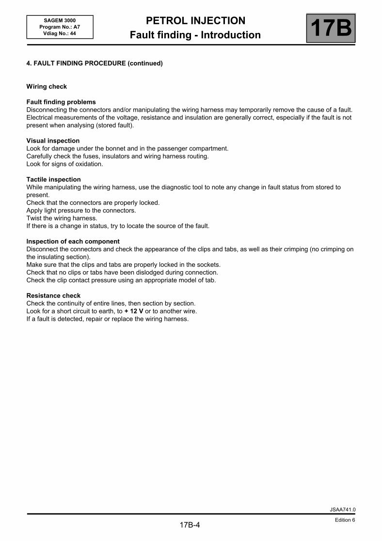
4. FAULT FINDING PROCEDURE (continued)
Wiring check
Fault finding problemsDisconnecting the connectors and/or manipulating the wiring harness may temporarily remove the cause of a fault.Electrical measurements of the voltage, resistance and insulation are generally correct, especially if the fault is not present when analysing (stored fault).
Visual inspectionLook for damage under the bonnet and in the passenger compartment.Carefully check the fuses, insulators and wiring harness routing.Look for signs of oxidation.
Tactile inspectionWhile manipulating the wiring harness, use the diagnostic tool to note any change in fault status from stored to present.Check that the connectors are properly locked.Apply light pressure to the connectors.Twist the wiring harness.If there is a change in status, try to locate the source of the fault.
Inspection of each componentDisconnect the connectors and check the appearance of the clips and tabs, as well as their crimping (no crimping on the insulating section).Make sure that the clips and tabs are properly locked in the sockets.Check that no clips or tabs have been dislodged during connection.Check the clip contact pressure using an appropriate model of tab.
Resistance checkCheck the continuity of entire lines, then section by section.Look for a short circuit to earth, to + 12 V or to another wire.If a fault is detected, repair or replace the wiring harness.
JSAA741.0
Edition 6
PETROL INJECTIONFault finding - Introduction 17B
17B-5
SAGEM 3000Program No.: A7
Vdiag No.: 44
5. FAULT FINDING LOG
You will always be asked for this log:– when requesting technical assistance from the Techline,– for approval requests when replacing parts for which approval is obligatory,– to be attached to monitored parts for which reimbursement is requested. The log is needed for warranty
reimbursement, and enables better analysis of the parts removed.
6. SAFETY ADVICE
Safety rules must be observed during any work on a component to prevent any damage or injury:– make sure that the battery is properly charged to avoid damaging the computers with a low load,– use the appropriate tools.
7. FAULT FINDING
Stored faults are managed the same way for all sensors and actuators.A stored fault is cleared after 128 recurrence-free starts.
IMPORTANT!
IMPORTANTAny fault on a complex system requires thorough fault finding with the appropriate tools. The FAULT FINDING LOG, which should be completed during the procedure, enables you to keep track of the procedure which is carried out. It is an essential document when consulting the manufacturer.
IT IS THEREFORE MANDATORY TO FILL OUT A FAULT FINDING LOG FOR EACH FAULT FINDING PROCEDURE.
JSAA741.0
Edition 6
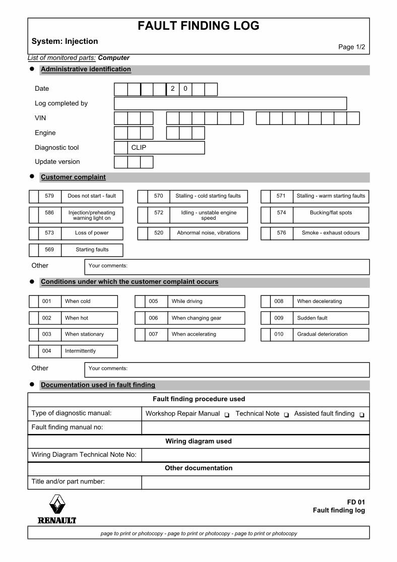
List of monitored parts: Computer
FAULT FINDING LOGSystem: Injection
Page 1/2
Administrative identification
Date 2 0
Log completed by
VIN
Engine
Diagnostic tool CLIP
Update version
Customer complaint
579 Does not start - fault 570 Stalling - cold starting faults 571 Stalling - warm starting faults
586 Injection/preheating warning light on
572 Idling - unstable engine speed
574 Bucking/flat spots
573 Loss of power 520 Abnormal noise, vibrations 576 Smoke - exhaust odours
569 Starting faults
Other Your comments:
Conditions under which the customer complaint occurs
001 When cold 005 While driving 008 When decelerating
002 When hot 006 When changing gear 009 Sudden fault
003 When stationary 007 When accelerating 010 Gradual deterioration
004 Intermittently
Other Your comments:
Documentation used in fault finding
Fault finding procedure used
Type of diagnostic manual: Workshop Repair Manual Technical Note Assisted fault finding
Fault finding manual no:
Wiring diagram used
Wiring Diagram Technical Note No:
Other documentation
Title and/or part number:
FD 01Fault finding log
page to print or photocopy - page to print or photocopy - page to print or photocopy
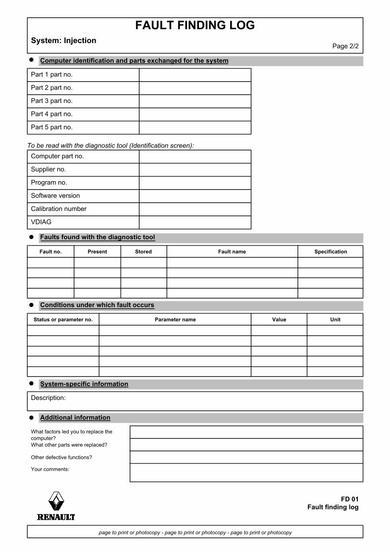
To be read with the diagnostic tool (Identification screen):
FAULT FINDING LOGSystem: Injection
Page 2/2
Computer identification and parts exchanged for the system
Part 1 part no.
Part 2 part no.
Part 3 part no.
Part 4 part no.
Part 5 part no.
Computer part no.
Supplier no.
Program no.
Software version
Calibration number
VDIAG
Faults found with the diagnostic tool
Fault no. Present Stored Fault name Specification
Conditions under which fault occurs
Status or parameter no. Parameter name Value Unit
System-specific information
Description:
Additional information
What factors led you to replace the computer?What other parts were replaced?
Other defective functions?
Your comments:
FD 01Fault finding log
page to print or photocopy - page to print or photocopy - page to print or photocopy
PETROL INJECTIONFault finding - System operation 17B
SAGEM 3000Program No.: A7
Vdiag No.: 44 Fault finding - System operation
1. SYSTEM OPERATION
Composition
The injection system consists of the:– accelerator potentiometer,– accelerator pedal switch,– TDC sensor,– atmospheric pressure sensor,– air temperature sensor,– coolant temperature sensor,– freon pressure sensor,– upstream oxygen sensor,– downstream oxygen sensor,– cruise control switch,– steering column switch,– cruise control on/off switch,– brake lights switch,– fuel vapour absorber,– injection computer,– motorised throttle valve,– four injectors,– four pencil coils,– + turbocharging pressure sensor,– coolant pump– turbocharging solenoid valve.
Computer
SAGEM type S3000 FLASH EEPROM 128-track computer controlling the injection and ignition.
Multipoint injection in sequential mode.
Connections to the other computers:– Protection and Switching Unit (UPC)– Passenger Compartment Control Unit (UCH),– Automatic Transmission Electronic Control Unit (AUTO ECU).
JSAA741.0
Edition 617B-8
PETROL INJECTIONFault finding - System operation 17B
17B-9
SAGEM 3000Program No.: A7
Vdiag No.: 44
Engine immobiliser
The immobiliser function is managed by the UCH and engine management computers.Before any driver request (card + button press), the engine management and UCH computers exchange authentication CAN frames to determine whether or not to start the engine.After more than five consecutive failed authentication attempts, the engine management computer goes into protection (anti-scanning) mode and no longer tries to authenticate the UCH computer. It only leaves this mode when the following sequence of operations is carried out:– the ignition is left on for at least 60 seconds,– ignition is switched off,– the injection computer self-supply cuts out when it should (the time varies according to engine temperature).After this, only one authentication attempt is allowed. If it too fails, the sequence of operations described above must be repeated.If the engine management computer still fails to unlock, contact the Techline.
Impact detected
If an impact has been registered by the injection computer (Impact detected), switch off the ignition for 10 seconds then switch it back on to start the engine. Then clear any faults.
WARNINGDisconnect the injection computer when carrying out any welding work on the vehicle.
JSAA741.0
Edition 6
PETROL INJECTIONFault finding - System operation 17B
17B-10
SAGEM 3000Program No.: A7
Vdiag No.: 44
2. OPERATIONAL SAFETY
Warning lights illumination
The S3000 injection system manages the illumination of three warning lights and the issuing of warning messages according to the severity of the faults detected, to inform the customer and to direct fault finding.The injection computer manages the illumination of warning lights and warning messages displayed on the instrument panel. These warning lights illuminate during the starting phase and in the event of an injection fault or engine overheating.The warning light illumination signals reach the instrument panel via the multiplex network.
Warning light illumination principle
During the starting phase (START button pressed) the OBD (On Board Diagnostic) warning light comes on for approximately 3 seconds then goes out.
If there is an injection fault (severity 1), the INJECTION FAULT written message lights up followed by the SERVICE warning light. It indicates a reduced level of operation and a limited safety level.The driver should carry out repairs as soon as possible.Components involved:– motorised throttle valve,– accelerator pedal potentiometer,– inlet manifold pressure sensor,– computer,– actuator feed,– computer feed.
If there is a serious injection fault (severity 2), the red engine symbol and the word STOP appear (display with information display only), with the ENGINE OVERHEATING written message followed by the STOP warning light and a buzzer. If this happens, the vehicle must be stopped immediately.When a fault causing excessive pollution in the exhaust fumes is detected, the orange OBD warning light, an engine symbol, will be lit:– flashing in the event of a fault which might irreparably damaged the catalytic converter (destructive misfiring). If
this happens, the vehicle must be stopped immediately.– constantly in the case of non-compliance with the anti-pollution standards (pollutant misfiring, catalytic converter
fault, oxygen sensor faults, inconsistency between the oxygen sensors and canister fault).
Mileage travelled with fault
This parameter counts the mileage travelled with one of the injection fault warning lights lit: level 1 fault warning light (amber), coolant temperature overheating warning light, or OBD warning light.The counter can be reset to 0 using the diagnostic tool.
JSAA741.0
Edition 6
PETROL INJECTIONFault finding - System operation 17B
17B-11
SAGEM 3000Program No.: A7
Vdiag No.: 44
Defect modes
Motorised throttle valveIn defect mode, the motorised throttle valve can have 6 different statuses.
Type 1The throttle opening is less than the Safe mode position. The throttle is no longer activated and is automatically in Safe mode. The ESP, distance control and cruise control/speed limiter systems are disabled. The automatic transmission is in "Safe mode".
Type 2The throttle opening is no longer actuated. The engine speed is limited by injection cut-off.
Type 3Defect mode is associated with restructuring of the pedal setpoints (constant pedal setpoint for each gear).
Type 4The associated defect mode restricts the throttle opening. The maximum throttle valve opening threshold results in a speed below 54 mph (90 km/h).
Type 5The computer no longer processes torque changes requested by the ESP, distance control, cruise control/speed limiter and automatic gearbox systems.This defect mode results from a computer malfunction, or a fault with the manifold or turbocharging pressure sensor.The system then only uses the accelerator pedal signal.The ESP, distance control and cruise control/speed limiter systems are disabled. The automatic transmission system is in Safe mode.
Type 6The turbocharging valve no longer works.
JSAA741.0
Edition 6
PETROL INJECTIONFault finding - System operation 17B
17B-12
SAGEM 3000Program No.: A7
Vdiag No.: 44
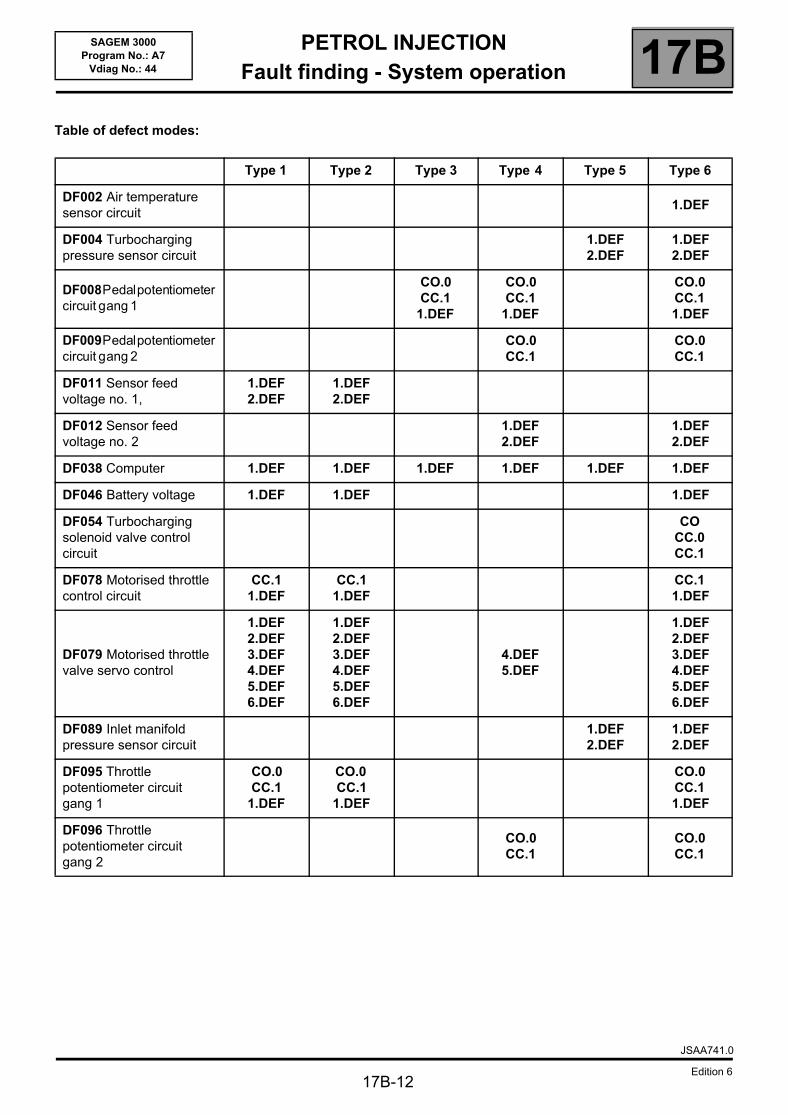
Table of defect modes:
Type 1 Type 2 Type 3 Type 4 Type 5 Type 6
DF002 Air temperature sensor circuit
1.DEF
DF004 Turbocharging pressure sensor circuit
1.DEF2.DEF
1.DEF2.DEF
DF008Pedalpotentiometercircuit gang 1
CO.0CC.1
1.DEF
CO.0CC.1
1.DEF
CO.0CC.11.DEF
DF009Pedalpotentiometercircuit gang 2
CO.0CC.1
CO.0CC.1
DF011 Sensor feed voltage no. 1,
1.DEF2.DEF
1.DEF2.DEF
DF012 Sensor feed voltage no. 2
1.DEF2.DEF
1.DEF2.DEF
DF038 Computer 1.DEF 1.DEF 1.DEF 1.DEF 1.DEF 1.DEF
DF046 Battery voltage 1.DEF 1.DEF 1.DEF
DF054 Turbocharging solenoid valve control circuit
COCC.0CC.1
DF078 Motorised throttle control circuit
CC.11.DEF
CC.11.DEF
CC.11.DEF
DF079 Motorised throttle valve servo control
1.DEF2.DEF3.DEF4.DEF5.DEF6.DEF
1.DEF2.DEF3.DEF4.DEF5.DEF6.DEF
4.DEF5.DEF
1.DEF2.DEF3.DEF4.DEF5.DEF6.DEF
DF089 Inlet manifold pressure sensor circuit
1.DEF2.DEF
1.DEF2.DEF
DF095 Throttle potentiometer circuit gang 1
CO.0CC.1
1.DEF
CO.0CC.1
1.DEF
CO.0CC.11.DEF
DF096 Throttle potentiometer circuit gang 2
CO.0CC.1
CO.0CC.1
JSAA741.0
Edition 6
PETROL INJECTIONFault finding - Allocation of computer tracks 17B
17B-13
SAGEM 3000Program No.: A7
Vdiag No.: 44 Fault finding - Allocation of computer tracks
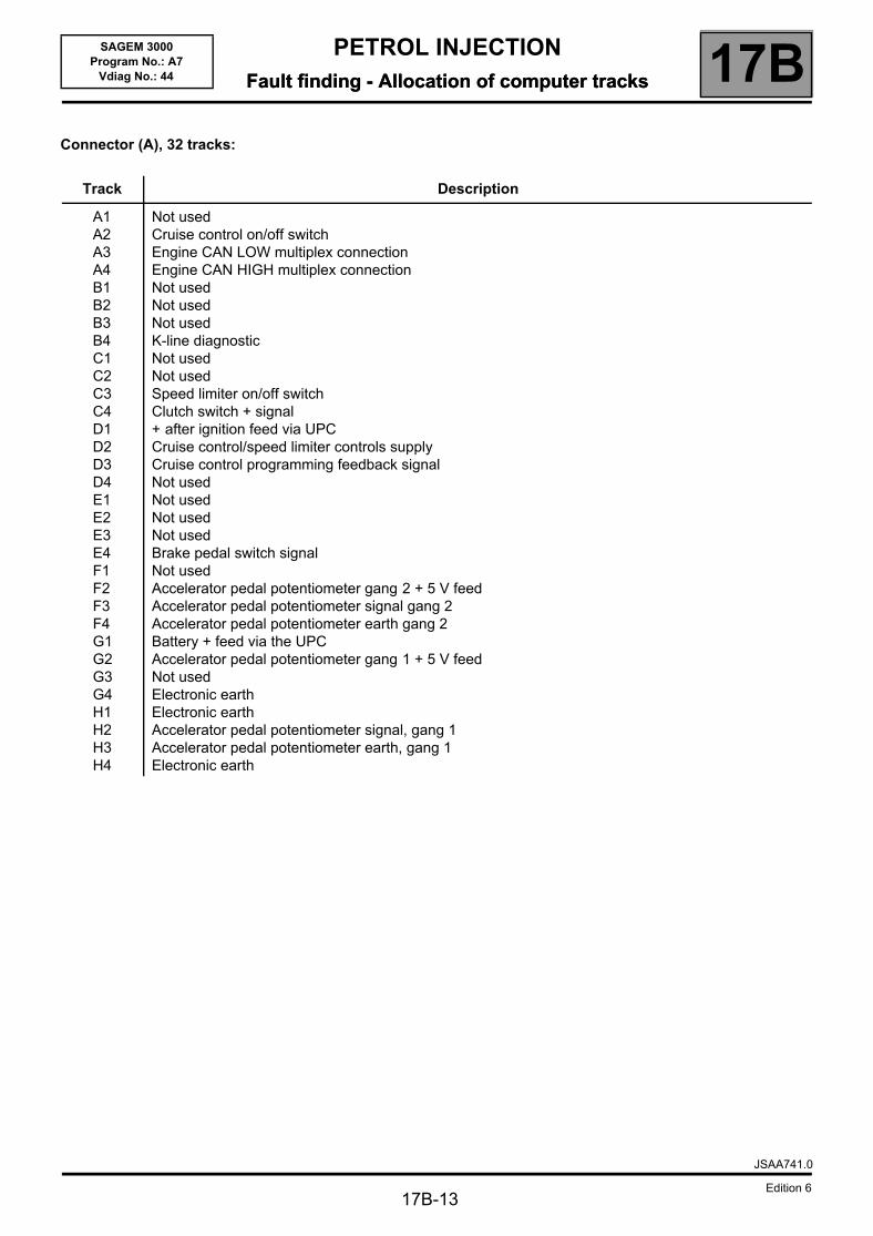
Connector (A), 32 tracks:
Track Description
A1A2A3A4B1B2B3B4C1C2C3C4D1D2D3D4E1E2E3E4F1F2F3F4G1G2G3G4H1H2H3H4
Not usedCruise control on/off switchEngine CAN LOW multiplex connectionEngine CAN HIGH multiplex connectionNot usedNot usedNot usedK-line diagnosticNot usedNot usedSpeed limiter on/off switchClutch switch + signal+ after ignition feed via UPCCruise control/speed limiter controls supplyCruise control programming feedback signalNot usedNot usedNot usedNot usedBrake pedal switch signalNot usedAccelerator pedal potentiometer gang 2 + 5 V feedAccelerator pedal potentiometer signal gang 2Accelerator pedal potentiometer earth gang 2Battery + feed via the UPCAccelerator pedal potentiometer gang 1 + 5 V feedNot usedElectronic earthElectronic earthAccelerator pedal potentiometer signal, gang 1Accelerator pedal potentiometer earth, gang 1Electronic earth
JSAA741.0
Edition 6
PETROL INJECTIONFault finding - Allocation of computer tracks 17B
17B-14
SAGEM 3000Program No.: A7
Vdiag No.: 44
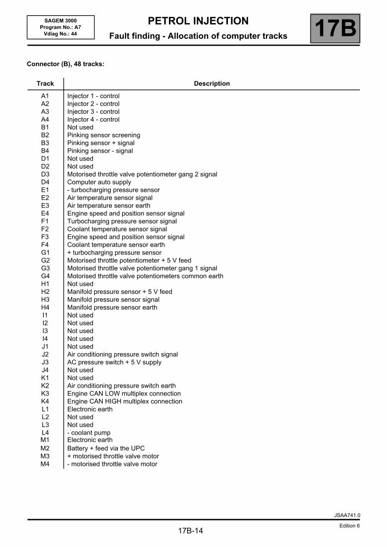
Connector (B), 48 tracks:
Track Description
A1A2A3A4B1B2B3B4D1D2D3D4E1E2E3E4F1F2F3F4G1G2G3G4H1H2H3H4I1I2I3I4J1J2J3J4K1K2K3K4L1L2L3L4M1M2M3M4
Injector 1 - controlInjector 2 - controlInjector 3 - controlInjector 4 - controlNot usedPinking sensor screeningPinking sensor + signalPinking sensor - signalNot usedNot usedMotorised throttle valve potentiometer gang 2 signalComputer auto supply- turbocharging pressure sensorAir temperature sensor signalAir temperature sensor earthEngine speed and position sensor signalTurbocharging pressure sensor signalCoolant temperature sensor signalEngine speed and position sensor signalCoolant temperature sensor earth+ turbocharging pressure sensorMotorised throttle potentiometer + 5 V feedMotorised throttle valve potentiometer gang 1 signalMotorised throttle valve potentiometers common earthNot usedManifold pressure sensor + 5 V feedManifold pressure sensor signalManifold pressure sensor earthNot usedNot usedNot usedNot usedNot usedAir conditioning pressure switch signalAC pressure switch + 5 V supplyNot usedNot usedAir conditioning pressure switch earthEngine CAN LOW multiplex connectionEngine CAN HIGH multiplex connectionElectronic earthNot usedNot used- coolant pumpElectronic earthBattery + feed via the UPC+ motorised throttle valve motor- motorised throttle valve motor
JSAA741.0
Edition 6
PETROL INJECTIONFault finding - Allocation of computer tracks 17B
17B-15
SAGEM 3000Program No.: A7
Vdiag No.: 44
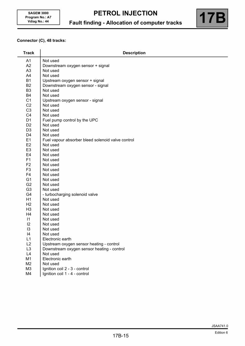
Connector (C), 48 tracks:
Track Description
A1A2A3A4B1B2B3B4C1C2C3C4D1D2D3D4E1E2E3E4F1F2F3F4G1G2G3G4H1H2H3H4I1I2I3I4L1L2L3L4M1M2M3M4
Not usedDownstream oxygen sensor + signalNot usedNot usedUpstream oxygen sensor + signalDownstream oxygen sensor - signalNot usedNot usedUpstream oxygen sensor - signalNot usedNot usedNot usedFuel pump control by the UPCNot usedNot usedNot usedFuel vapour absorber bleed solenoid valve controlNot usedNot usedNot usedNot usedNot usedNot usedNot usedNot usedNot usedNot used- turbocharging solenoid valveNot usedNot usedNot usedNot usedNot usedNot usedNot usedNot usedElectronic earthUpstream oxygen sensor heating - controlDownstream oxygen sensor heating - controlNot usedElectronic earthNot usedIgnition coil 2 - 3 - controlIgnition coil 1 - 4 - control
JSAA741.0
Edition 6
PETROL INJECTIONFault finding - Replacement of components 17B
17B-16
SAGEM 3000Program No.: A7
Vdiag No.: 44 Fault finding - Replacement of components
1. PROGRAMMING, REPROGRAMMING OR REPLACING THE COMPUTER
The system can be programmed and reprogrammed via the diagnostic socket using the RENAULT CLIP diagnostic tool (Consult Technical Note 3585A or follow the instructions provided by the diagnostic tool).
Whenever the computer has been programmed, reprogrammed or replaced:– switch off the ignition.– start and then stop the engine (to initialise the computer) and wait for 30 seconds.– switch on the ignition again and use the diagnostic tool to carry out the following steps:
– run command VP010 Enter VIN,– deal with any faults declared by the diagnostic tool. Clear the computer memory,– program the flywheel sensor target and throttle stops,– carry out a road test followed by another check with the diagnostic tool.
2. REPLACING OR REMOVING THE TDC SENSOR
When the TDC sensor is replaced or removed, the flywheel target has to be programmed.
3. REPLACING THE MOTORISED THROTTLE VALVE
When the throttle valve is replaced, the throttle stops must be programmed.
IMPORTANT– switch on the diagnostic tool (mains or cigarette lighter supply).– connect a battery charger (during the entire computer (re)programming procedure, the engine fan
assemblies are triggered automatically).– observe the engine temperature instructions of the diagnostic tool before (re)programming.
IMPORTANTIt is not possible to test an injection computer from the Parts Department because it can no longer be fitted on any other vehicle.
IMPORTANTNever drive the vehicle without having programmed the throttle stops.
JSAA741.0
Edition 6
PETROL INJECTIONFault finding - Configurations and programming 17B
17B-17
SAGEM 3000Program No.: A7
Vdiag No.: 44 Fault finding - Configurations and programming
1. CONFIGURATION
Computer configuration by automatic detection
The computer can automatically configure itself based on the sensors or vehicle options it detects.
2. PROGRAMMING
Programming the flywheel target
Accelerate up to 4000 rpm in 3rd gear then decelerate to power take-up* speed. Then repeat immediately.Check the programming with ET089.
Programming the throttle end stops
After replacing the computer or motorised throttle valve, after switching on the ignition, wait 30 seconds for the computer to memorise the MAXIMUM and MINIMUM stops.Check the programming with ET051.
* This is the moment when, during deceleration with no load, the engine drops to idling speed and recovers torque.
JSAA741.0
Edition 6
PETROL INJECTIONFault finding - Fault summary table 17B
17B-18
SAGEM 3000Program No.: A7
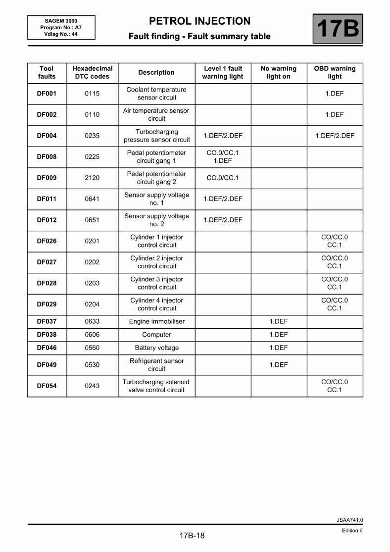
Vdiag No.: 44 Fault finding - Fault summary table
Tool faults
Hexadecimal DTC codes
DescriptionLevel 1 fault
warning lightNo warning
light onOBD warning
light
DF001 0115Coolant temperature
sensor circuit1.DEF
DF002 0110Air temperature sensor
circuit1.DEF
DF004 0235Turbocharging
pressure sensor circuit1.DEF/2.DEF 1.DEF/2.DEF
DF008 0225Pedal potentiometer
circuit gang 1CO.0/CC.1
1.DEF
DF009 2120Pedal potentiometer
circuit gang 2CO.0/CC.1
DF011 0641Sensor supply voltage
no. 11.DEF/2.DEF
DF012 0651Sensor supply voltage
no. 21.DEF/2.DEF
DF026 0201Cylinder 1 injector
control circuitCO/CC.0
CC.1
DF027 0202Cylinder 2 injector
control circuitCO/CC.0
CC.1
DF028 0203Cylinder 3 injector
control circuitCO/CC.0
CC.1
DF029 0204Cylinder 4 injector
control circuitCO/CC.0
CC.1
DF037 0633 Engine immobiliser 1.DEF
DF038 0606 Computer 1.DEF
DF046 0560 Battery voltage 1.DEF
DF049 0530Refrigerant sensor
circuit1.DEF
DF054 0243Turbocharging solenoid
valve control circuitCO/CC.0
CC.1
JSAA741.0
Edition 6
PETROL INJECTIONFault finding - Fault summary table 17B
17B-19
SAGEM 3000Program No.: A7
Vdiag No.: 44
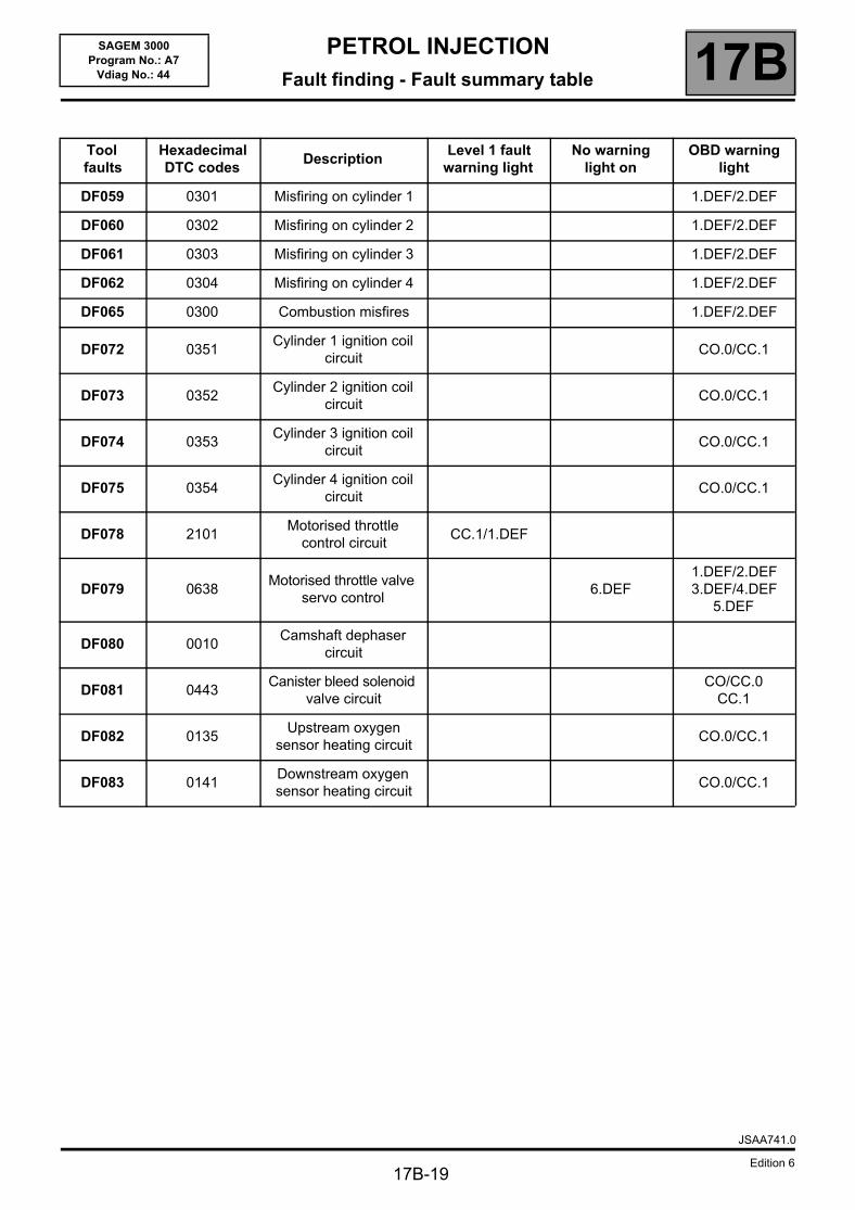
Tool faults
Hexadecimal DTC codes
DescriptionLevel 1 fault
warning lightNo warning
light onOBD warning
light
DF059 0301 Misfiring on cylinder 1 1.DEF/2.DEF
DF060 0302 Misfiring on cylinder 2 1.DEF/2.DEF
DF061 0303 Misfiring on cylinder 3 1.DEF/2.DEF
DF062 0304 Misfiring on cylinder 4 1.DEF/2.DEF
DF065 0300 Combustion misfires 1.DEF/2.DEF
DF072 0351Cylinder 1 ignition coil
circuitCO.0/CC.1
DF073 0352Cylinder 2 ignition coil
circuitCO.0/CC.1
DF074 0353Cylinder 3 ignition coil
circuitCO.0/CC.1
DF075 0354Cylinder 4 ignition coil
circuitCO.0/CC.1
DF078 2101Motorised throttle
control circuitCC.1/1.DEF
DF079 0638Motorised throttle valve
servo control6.DEF
1.DEF/2.DEF3.DEF/4.DEF
5.DEF
DF080 0010Camshaft dephaser
circuit
DF081 0443Canister bleed solenoid
valve circuitCO/CC.0
CC.1
DF082 0135Upstream oxygen
sensor heating circuitCO.0/CC.1
DF083 0141Downstream oxygen sensor heating circuit
CO.0/CC.1
JSAA741.0
Edition 6
PETROL INJECTIONFault finding - Fault summary table 17B
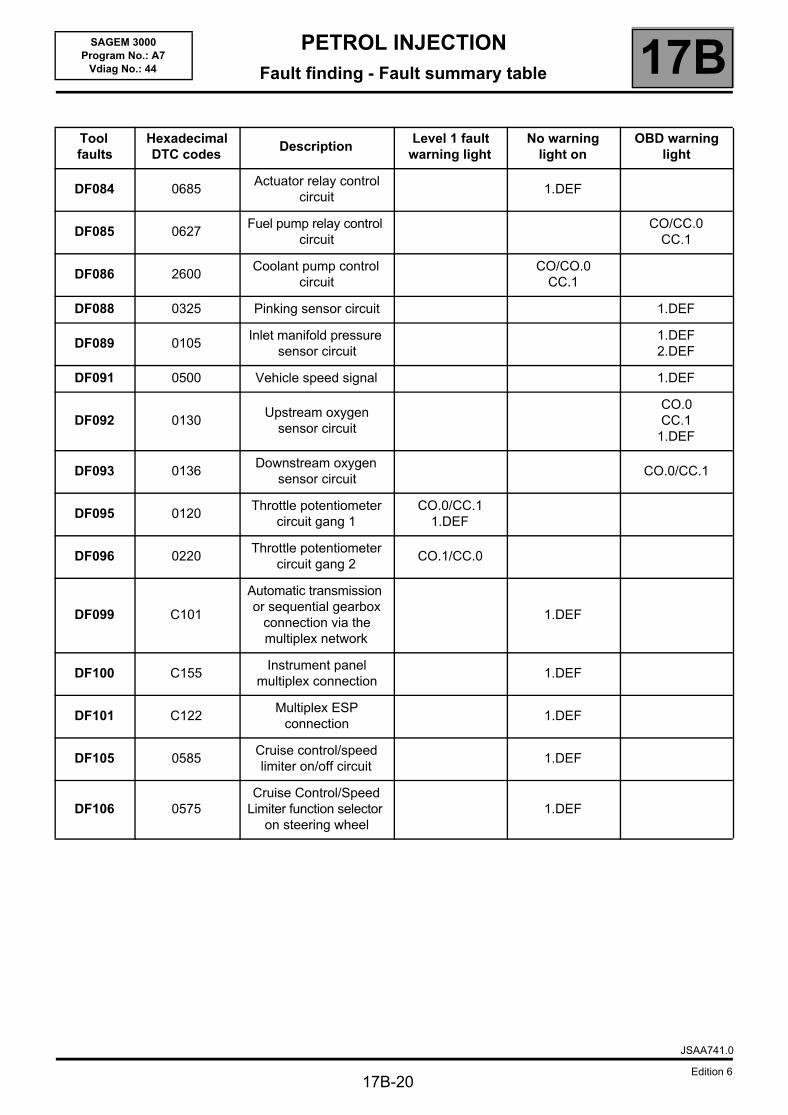
17B-20
SAGEM 3000Program No.: A7
Vdiag No.: 44
Tool faults
Hexadecimal DTC codes
DescriptionLevel 1 fault
warning lightNo warning
light onOBD warning
light
DF084 0685Actuator relay control
circuit1.DEF
DF085 0627Fuel pump relay control
circuitCO/CC.0
CC.1
DF086 2600Coolant pump control
circuitCO/CO.0
CC.1
DF088 0325 Pinking sensor circuit 1.DEF
DF089 0105Inlet manifold pressure
sensor circuit1.DEF2.DEF
DF091 0500 Vehicle speed signal 1.DEF
DF092 0130Upstream oxygen
sensor circuit
CO.0CC.1
1.DEF
DF093 0136Downstream oxygen
sensor circuitCO.0/CC.1
DF095 0120Throttle potentiometer
circuit gang 1CO.0/CC.1
1.DEF
DF096 0220Throttle potentiometer
circuit gang 2CO.1/CC.0
DF099 C101
Automatic transmission or sequential gearbox
connection via the multiplex network
1.DEF
DF100 C155Instrument panel
multiplex connection1.DEF
DF101 C122Multiplex ESP
connection1.DEF
DF105 0585Cruise control/speed limiter on/off circuit
1.DEF
DF106 0575Cruise Control/Speed
Limiter function selector on steering wheel
1.DEF
JSAA741.0
Edition 6
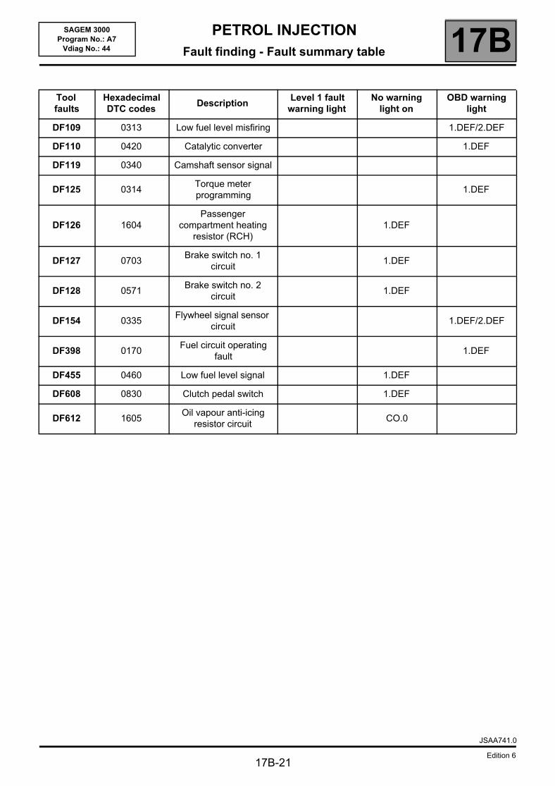
PETROL INJECTIONFault finding - Fault summary table 17B
17B-21
SAGEM 3000Program No.: A7
Vdiag No.: 44
Tool faults
Hexadecimal DTC codes
DescriptionLevel 1 fault
warning lightNo warning
light onOBD warning
light
DF109 0313 Low fuel level misfiring 1.DEF/2.DEF
DF110 0420 Catalytic converter 1.DEF
DF119 0340 Camshaft sensor signal
DF125 0314Torque meter programming
1.DEF
DF126 1604Passenger
compartment heating resistor (RCH)
1.DEF
DF127 0703Brake switch no. 1
circuit1.DEF
DF128 0571Brake switch no. 2
circuit1.DEF
DF154 0335Flywheel signal sensor
circuit1.DEF/2.DEF
DF398 0170Fuel circuit operating
fault1.DEF
DF455 0460 Low fuel level signal 1.DEF
DF608 0830 Clutch pedal switch 1.DEF
DF612 1605Oil vapour anti-icing
resistor circuitCO.0
JSAA741.0
Edition 6
PETROL INJECTIONFault finding - Interpretation of faults 17B
17B-22
SAGEM 3000Program No.: A7
Vdiag No.: 44 Fault finding - Interpretation of faults
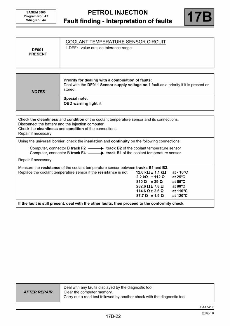
DF001PRESENT
COOLANT TEMPERATURE SENSOR CIRCUIT1.DEF: value outside tolerance range
NOTES
Priority for dealing with a combination of faults:Deal with the DF011 Sensor supply voltage no 1 fault as a priority if it is present or stored.
Special note:OBD warning light lit.
Check the cleanliness and condition of the coolant temperature sensor and its connections.Disconnect the battery and the injection computer.Check the cleanliness and condition of the connections. Repair if necessary.
Using the universal bornier, check the insulation and continuity on the following connections:
Computer, connector B track F2 track B2 of the coolant temperature sensorComputer, connector B track F4 track B1 of the coolant temperature sensor
Repair if necessary.
Measure the resistance of the coolant temperature sensor between tracks B1 and B2.Replace the coolant temperature sensor if the resistance is not: 12.6 kΩΩΩΩ ±±±± 1.1 kΩΩΩΩ at - 10°°°°C
2.2 kΩΩΩΩ ±±±± 112 ΩΩΩΩ at 25°°°°C810 ΩΩΩΩ ±±±± 39 ΩΩΩΩ at 50°°°°C282.6 ΩΩΩΩ ±±±± 7.8 ΩΩΩΩ at 80°°°°C114.6 ΩΩΩΩ ±±±± 2.6 ΩΩΩΩ at 110°°°°C87.7 ΩΩΩΩ ±±±± 1.9 ΩΩΩΩ at 120°°°°C
If the fault is still present, deal with the other faults, then proceed to the conformity check.
AFTER REPAIRDeal with any faults displayed by the diagnostic tool.Clear the computer memory.Carry out a road test followed by another check with the diagnostic tool.
JSAA741.0
Edition 6
PETROL INJECTIONFault finding - Interpretation of faults 17B
17B-23
SAGEM 3000Program No.: A7
Vdiag No.: 44
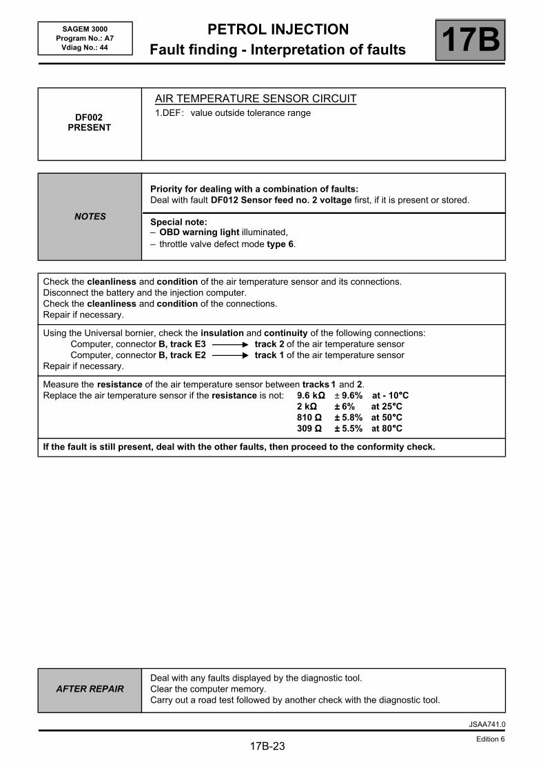
DF002PRESENT
AIR TEMPERATURE SENSOR CIRCUIT1.DEF: value outside tolerance range
NOTES
Priority for dealing with a combination of faults:Deal with fault DF012 Sensor feed no. 2 voltage first, if it is present or stored.
Special note:– OBD warning light illuminated,– throttle valve defect mode type 6.
Check the cleanliness and condition of the air temperature sensor and its connections.Disconnect the battery and the injection computer.Check the cleanliness and condition of the connections. Repair if necessary.
Using the Universal bornier, check the insulation and continuity of the following connections:Computer, connector B, track E3 track 2 of the air temperature sensorComputer, connector B, track E2 track 1 of the air temperature sensor
Repair if necessary.
Measure the resistance of the air temperature sensor between tracks 1 and 2.Replace the air temperature sensor if the resistance is not: 9.6 kΩΩΩΩ ± 9.6% at - 10°°°°C
2 kΩΩΩΩ ±±±± 6% at 25°°°°C810 ΩΩΩΩ ±±±± 5.8% at 50°°°°C309 ΩΩΩΩ ±±±± 5.5% at 80°°°°C
If the fault is still present, deal with the other faults, then proceed to the conformity check.
AFTER REPAIRDeal with any faults displayed by the diagnostic tool.Clear the computer memory.Carry out a road test followed by another check with the diagnostic tool.
JSAA741.0
Edition 6
PETROL INJECTIONFault finding - Interpretation of faults 17B
17B-24
SAGEM 3000Program No.: A7
Vdiag No.: 44
DF004PRESENT
ORSTORED
TURBOCHARGING PRESSURE SENSOR CIRCUIT1.DEF: voltage outside tolerances2.DEF: inconsistent data
NOTES
Priority for dealing with a combination of faults:Deal with fault DF012 Sensor feed no. 2 voltage first, if it is present or stored.
Conditions for applying the fault finding procedure to stored faults:The fault is declared present after the engine has been running or started at an engine speed above 600 rpm.
Special note:– OBD warning light illuminated,– throttle valve defect mode types 5 and 6.
Check the cleanliness, condition and the assembly of the turbocharging pressure sensor.Repair if necessary.
If the fault is still present, adjust the harness so that the fault status changes (present ⇒ stored).Look for any damage to the wiring harness, and check the condition and connection of the injection computer and turbocharging pressure sensor connectors.Repair if necessary.
If the fault is still present, check for + 5 V on track G1 and that the earth is present on track E1 of connector B of the injection computer.Contact the Techline if it is not correct.
If the fault is still present, disconnect the battery and the injection computer.Check the insulation, continuity and the absence of interference resistance on the following connections:
Computer connector B, track E1 Track 2 of the pressure sensorComputer connector B, track F1 Track 3 of the pressure sensorComputer connector B, track G1 Track 1 of the pressure sensor
Repair if necessary.
If the fault is still present, deal with the other faults, then proceed to the conformity check.
AFTER REPAIRFollow the instructions to confirm the repair:Deal with any other faults.Clear the stored faults.
JSAA741.0
Edition 6
PETROL INJECTIONFault finding - Interpretation of faults 17B
17B-25
SAGEM 3000Program No.: A7
Vdiag No.: 44
DF008PRESENT
ORSTORED
PEDAL POTENTIOMETER CIRCUIT GANG 1CO.0 : open circuit or short circuit to earthCC.1 : short circuit to + 12 V1.DEF: inconsistency between pedal gangs 1 and 2
NOTES
Priority for dealing with a combination of faults:Deal with fault DF011 Sensor supply voltage no. 1 first if it is present or stored.
Conditions for applying the fault finding procedure to stored faults:The fault appears after the accelerator pedal goes from no load to full load.
Special note:– OBD fault warning light and severity 1 fault warning light illuminated,– throttle valve defect mode types 3, 4 and 6.
Check that the pedal mechanism has not seized.
Check the cleanliness and condition of the throttle valve connections.Check the cleanliness and condition of the pedal potentiometer connections.Disconnect the battery and the injection computer.Check the cleanliness and condition of the connections.Repair if necessary.
Using the Universal bornier, check the insulation and continuity of the following connections:Computer, connector A, track H3 Track 5 of the pedal potentiometer gang 1Computer, connector A, track G2 Track 3 of the pedal potentiometer gang 1Computer, connector A, track H2 Track 4 of the pedal potentiometer gang 1
Repair if necessary.
If the fault is still present, contact the Techline.
AFTER REPAIRDeal with any faults displayed by the diagnostic tool.Clear the computer memory.Carry out a road test followed by another check with the diagnostic tool.
JSAA741.0
Edition 6
PETROL INJECTIONFault finding - Interpretation of faults 17B
17B-26
SAGEM 3000Program No.: A7
Vdiag No.: 44
DF009PRESENT
ORSTORED
PEDAL POTENTIOMETER CIRCUIT GANG 2CO.0 : open circuit or short circuit to earthCC.1 : short circuit to + 12 V
NOTES
Priority for dealing with a combination of faults:Deal with fault DF012 Sensor feed no. 2 voltage first, if it is present or stored.
Conditions for applying the fault finding procedure to stored faults:The fault appears after the accelerator pedal goes from no load to full load.
Special note:– level 1 fault warning light illuminated,– throttle valve defect mode types 4 and 6.
Check that the pedal mechanism has not seized.
Check the cleanliness and condition of the throttle valve connections.Check the cleanliness and condition of the pedal potentiometer connections.Disconnect the battery and the injection computer.Check the cleanliness and condition of the connections.Repair if necessary.
Using the Universal bornier, check for insulation and continuity on the following connections:Computer, connector A, track F4 Track 6 of the pedal potentiometer gang 2Computer, connector A, track F2 Track 2 of the pedal potentiometer gang 2Computer, connector A, track F3 Track 1 of the pedal potentiometer gang 2
Repair if necessary.
If the fault is still present, contact the Techline.
AFTER REPAIRDeal with any faults displayed by the diagnostic tool.Clear the computer memory.Carry out a road test followed by another check with the diagnostic tool.
JSAA741.0
Edition 6
PETROL INJECTIONFault finding - Interpretation of faults 17B
17B-27
SAGEM 3000Program No.: A7
Vdiag No.: 44
DF011PRESENT
ORSTORED
SENSOR SUPPLY VOLTAGE NO. 11.DEF: voltage outside tolerances2.DEF: internal electronic fault
NOTES
Priority for dealing with a combination of faults:Deal with the other faults first.
Conditions for applying the fault finding procedure to stored faults:The fault appears after:– the ignition is switched on.– loss of dialogue between the inter-systems (ESP, CC/SL),– power loss when accelerating.
Special note:– level 1 fault warning light illuminated,– throttle valve defect mode types 1 and 2.
Check the cleanliness and condition of the throttle valve connections.Check the cleanliness and condition of the pedal potentiometer connections.Disconnect the battery and the injection computer.Check the cleanliness and condition of the connections.Repair if necessary.
Sensor feed No. 1 is reserved for the following components:– motorised throttle valve,– coolant temperature sensor,– pedal potentiometer gang 1,– upstream and downstream oxygen sensors,– motorised throttle potentiometer gangs 1 and 2.
If, with sensors disconnected the voltage is still less than 4.9 V or greater than 5.1 V:– check the insulation from earth of the + 5 V line of each of its sensors.
Using the Universal bornier, check the insulation and continuity of the following connections:Computer, connector B, track G2 Track 2 of the throttle valveComputer, connector A, track G2 Track 3 of the pedal potentiometer gang 1
Repair if necessary.
If the fault is still present, there is a computer fault. Contact Techline.
AFTER REPAIRDeal with any faults displayed by the diagnostic tool.Clear the computer memory.Carry out a road test followed by another check with the diagnostic tool.
JSAA741.0
Edition 6
PETROL INJECTIONFault finding - Interpretation of faults 17B
17B-28
SAGEM 3000Program No.: A7
Vdiag No.: 44
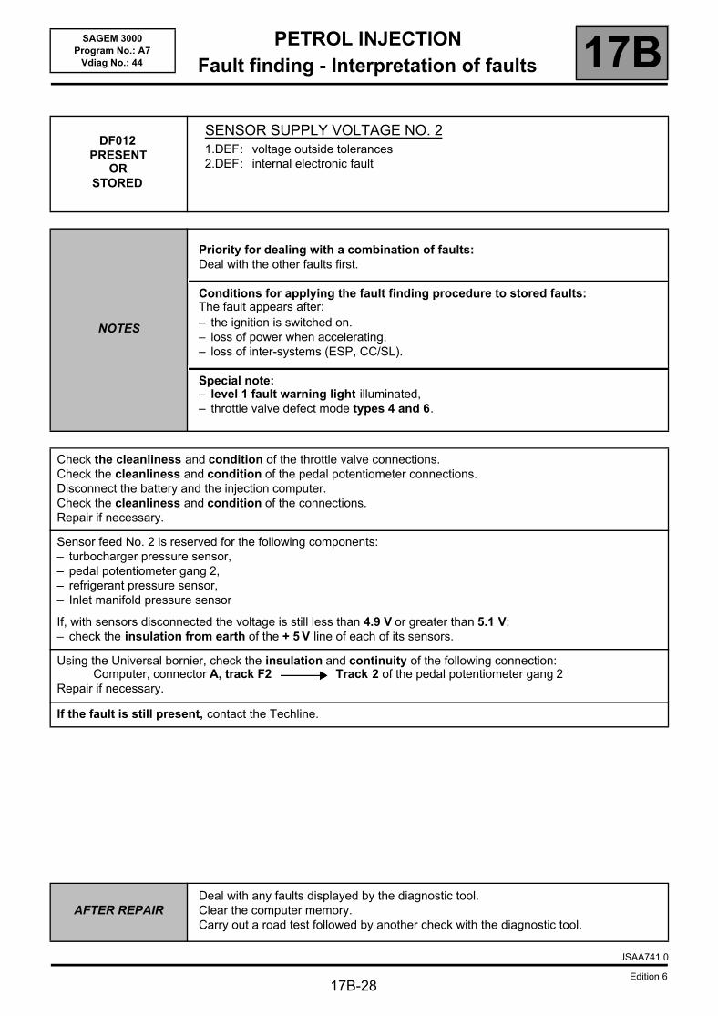
DF012PRESENT
ORSTORED
SENSOR SUPPLY VOLTAGE NO. 21.DEF: voltage outside tolerances2.DEF: internal electronic fault
NOTES
Priority for dealing with a combination of faults:Deal with the other faults first.
Conditions for applying the fault finding procedure to stored faults:The fault appears after:– the ignition is switched on.– loss of power when accelerating,– loss of inter-systems (ESP, CC/SL).
Special note:– level 1 fault warning light illuminated,– throttle valve defect mode types 4 and 6.
Check the cleanliness and condition of the throttle valve connections.Check the cleanliness and condition of the pedal potentiometer connections.Disconnect the battery and the injection computer.Check the cleanliness and condition of the connections.Repair if necessary.
Sensor feed No. 2 is reserved for the following components:– turbocharger pressure sensor,– pedal potentiometer gang 2,– refrigerant pressure sensor,– Inlet manifold pressure sensor
If, with sensors disconnected the voltage is still less than 4.9 V or greater than 5.1 V:– check the insulation from earth of the + 5 V line of each of its sensors.
Using the Universal bornier, check the insulation and continuity of the following connection:Computer, connector A, track F2 Track 2 of the pedal potentiometer gang 2
Repair if necessary.
If the fault is still present, contact the Techline.
AFTER REPAIRDeal with any faults displayed by the diagnostic tool.Clear the computer memory.Carry out a road test followed by another check with the diagnostic tool.
JSAA741.0
Edition 6

PETROL INJECTIONFault finding - Interpretation of faults 17B
17B-29
SAGEM 3000Program No.: A7
Vdiag No.: 44
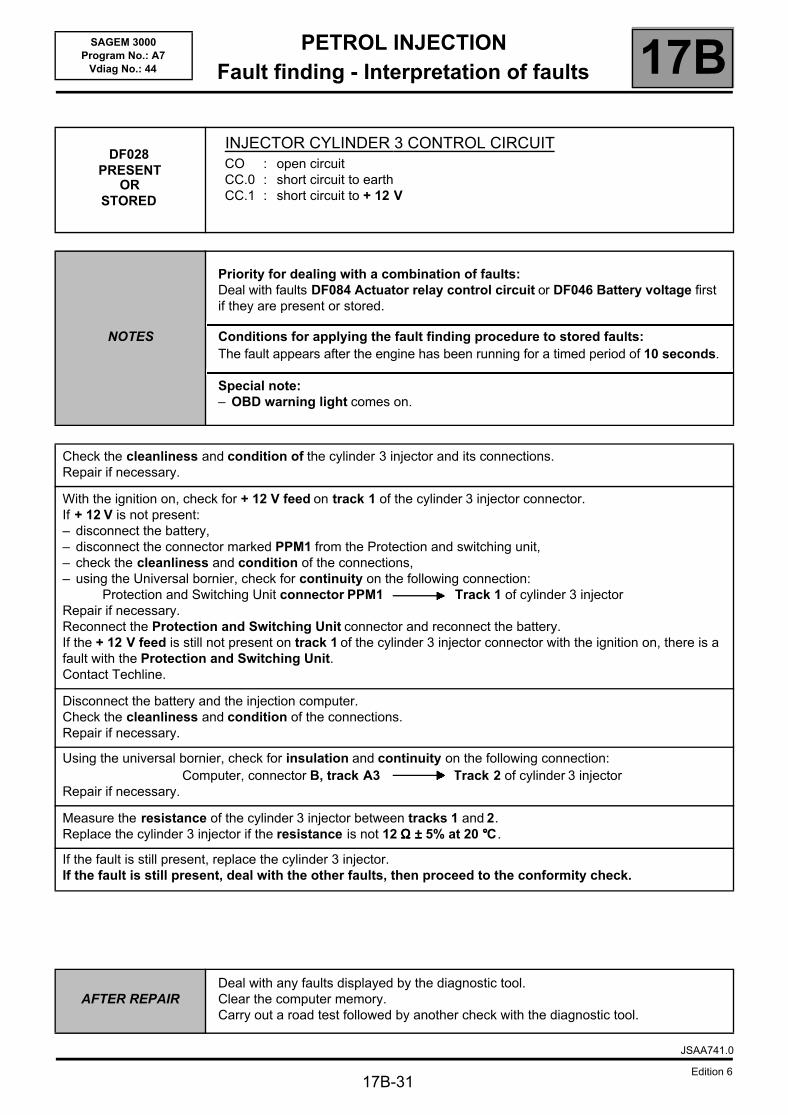
DF026PRESENT
ORSTORED
CYLINDER 1 INJECTOR CONTROL CIRCUITCO : open circuitCC.0 : short circuit to earthCC.1 : short circuit to + 12 V
NOTES
Priority for dealing with a combination of faults:Deal with faults DF084 Actuator relay control circuit or DF046 Battery voltage first if they are present or stored.
Conditions for applying the fault finding procedure to stored faults:The fault appears after the engine has been running for a timed period of 10 seconds.
Special note:– OBD warning light comes on.
Check the cleanliness and condition of the cylinder 1 injector and its connections.Repair if necessary.
With the ignition on, check for a + 12 V feed on track 1 of the cylinder 1 injector connector.If + 12 V is not present:– disconnect the battery,– disconnect the connector marked PPM1 from the Protection and switching unit,– check the cleanliness and condition of the connections,– using the Universal bornier, check for continuity on the following connection:
Protection and Switching Unit connector PPM1 Track 1 of cylinder 1 injectorRepair if necessary.Reconnect the Protection and Switching Unit connector and reconnect the battery.If the + 12 V feed is still not present on track 1 of the cylinder 1 injector connector with the ignition on, there is a fault with the Protection and Switching Unit.Contact Techline.
Disconnect the battery and the injection computer.Check the cleanliness and condition of the connections.Repair if necessary.
Using the Universal bornier, check for insulation and continuity on the following connection:Computer, connector B, track A1 Track 2 of cylinder 1 injector
Repair if necessary.
Measure the resistance of cylinder 1 injector between tracks 1 and 2.Replace the cylinder 1 injector if the resistance is not 12 ΩΩΩΩ ±±±± 5% at 20 °°°°C.
If the fault is still present, replace the cylinder 1 injector.If the fault is still present, deal with the other faults, then proceed to the conformity check.
AFTER REPAIRDeal with any faults displayed by the diagnostic tool.Clear the computer memory.Carry out a road test followed by another check with the diagnostic tool.
JSAA741.0
Edition 6

PETROL INJECTIONFault finding - Interpretation of faults 17B
17B-30
SAGEM 3000Program No.: A7
Vdiag No.: 44
DF027PRESENT
ORSTORED
CYLINDER 2 INJECTOR CONTROL CIRCUITCO : open circuitCC.0 : short circuit to earthCC.1 : short circuit to + 12 V
NOTES
Priority for dealing with a combination of faults:Deal with faults DF084 Actuator relay control circuit or DF046 Battery voltage first if they are present or stored.
Conditions for applying the fault finding procedure to stored faults:The fault appears after the engine has been running for a timed period of 10 seconds.
Special note:– OBD warning light comes on.
Check the cleanliness and condition of the cylinder 2 injector and its connections.Repair if necessary.
With the ignition on, check for + 12 V feed on track 1 of the cylinder 2 injector connector.If + 12 V is not present:– disconnect the battery,– disconnect the connector marked PPM1 from the Protection and switching unit,– check the cleanliness and condition of the connections,– using the Universal bornier, check for continuity on the following connection:
Protection and Switching Unit connector PPM1 Track 1 of cylinder 2 injectorRepair if necessary.Reconnect the Protection and Switching Unit connector and reconnect the battery.If the + 12 V feed on track 1 is still not present on the cylinder 2 injector connector with the ignition on, there is a fault with the Protection and Switching Unit.Contact Techline.
Disconnect the battery and the injection computer.Check the cleanliness and condition of the connections.Repair if necessary.
Using the universal bornier, check for insulation and continuity on the following connection:Computer, connector B, track A2 Track 2 of cylinder 2 injector
Repair if necessary.
Measure the resistance of the cylinder 2 injector between tracks 1 and 2.Replace the cylinder 2 injector if the resistance is not 12 ΩΩΩΩ ±±±± 5% at 20 °°°°C.
If the fault is still present, replace the cylinder 2 injector.If the fault is still present, deal with the other faults, then proceed to the conformity check.
AFTER REPAIRDeal with any faults displayed by the diagnostic tool.Clear the computer memory.Carry out a road test followed by another check with the diagnostic tool.
JSAA741.0
Edition 6
PETROL INJECTIONFault finding - Interpretation of faults 17B
17B-31
SAGEM 3000Program No.: A7
Vdiag No.: 44
DF028PRESENT
ORSTORED
INJECTOR CYLINDER 3 CONTROL CIRCUITCO : open circuitCC.0 : short circuit to earthCC.1 : short circuit to + 12 V
NOTES
Priority for dealing with a combination of faults:Deal with faults DF084 Actuator relay control circuit or DF046 Battery voltage first if they are present or stored.
Conditions for applying the fault finding procedure to stored faults:The fault appears after the engine has been running for a timed period of 10 seconds.
Special note:– OBD warning light comes on.
Check the cleanliness and condition of the cylinder 3 injector and its connections.Repair if necessary.
With the ignition on, check for + 12 V feed on track 1 of the cylinder 3 injector connector.If + 12 V is not present:– disconnect the battery,– disconnect the connector marked PPM1 from the Protection and switching unit,– check the cleanliness and condition of the connections,– using the Universal bornier, check for continuity on the following connection:
Protection and Switching Unit connector PPM1 Track 1 of cylinder 3 injectorRepair if necessary.Reconnect the Protection and Switching Unit connector and reconnect the battery.If the + 12 V feed is still not present on track 1 of the cylinder 3 injector connector with the ignition on, there is a fault with the Protection and Switching Unit.Contact Techline.
Disconnect the battery and the injection computer.Check the cleanliness and condition of the connections.Repair if necessary.
Using the universal bornier, check for insulation and continuity on the following connection:Computer, connector B, track A3 Track 2 of cylinder 3 injector
Repair if necessary.
Measure the resistance of the cylinder 3 injector between tracks 1 and 2.Replace the cylinder 3 injector if the resistance is not 12 ΩΩΩΩ ±±±± 5% at 20 °°°°C.
If the fault is still present, replace the cylinder 3 injector.If the fault is still present, deal with the other faults, then proceed to the conformity check.
AFTER REPAIRDeal with any faults displayed by the diagnostic tool.Clear the computer memory.Carry out a road test followed by another check with the diagnostic tool.
JSAA741.0
Edition 6
PETROL INJECTIONFault finding - Interpretation of faults 17B
17B-32
SAGEM 3000Program No.: A7
Vdiag No.: 44
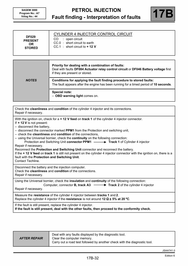
DF029PRESENT
OR STORED
CYLINDER 4 INJECTOR CONTROL CIRCUITCO : open circuitCC.0 : short circuit to earthCC.1 : short circuit to + 12 V
NOTES
Priority for dealing with a combination of faults:Deal with faults DF084 Actuator relay control circuit or DF046 Battery voltage first if they are present or stored.
Conditions for applying the fault finding procedure to stored faults:The fault appears after the engine has been running for a timed period of 10 seconds.
Special note:– OBD warning light comes on.
Check the cleanliness and condition of the cylinder 4 injector and its connections.Repair if necessary.
With the ignition on, check for a + 12 V feed on track 1 of the cylinder 4 injector connector.If + 12 V is not present:– disconnect the battery,– disconnect the connector marked PPM1 from the Protection and switching unit,– check the cleanliness and condition of the connections,– using the Universal bornier, check the continuity on the following connection:
Protection and Switching Unit connector PPM1 Track 1 of Cylinder 4 injectorRepair if necessary.Reconnect the Protection and Switching Unit connector and reconnect the battery.If the + 12 V feed on track 1 is still not present on the cylinder 4 injector connector with the ignition on, there is a fault with the Protection and Switching Unit.Contact Techline.
Disconnect the battery and the injection computer.Check the cleanliness and condition of the connections.Repair if necessary.
Using the Universal bornier, check the insulation and continuity of the following connection:Computer, connector B, track A3 Track 2 of the cylinder 4 injector
Repair if necessary.
Measure the resistance of the cylinder 4 injector between tracks 1 and 2.Replace the cylinder 4 injector if the resistance is not around 12 ΩΩΩΩ ±±±± 5% at 20 °°°°C.
If the fault is still present, replace the cylinder 4 injector.If the fault is still present, deal with the other faults, then proceed to the conformity check.
AFTER REPAIRDeal with any faults displayed by the diagnostic tool.Clear the computer memory.Carry out a road test followed by another check with the diagnostic tool.
JSAA741.0
Edition 6
PETROL INJECTIONFault finding - Interpretation of faults 17B
17B-33
SAGEM 3000Program No.: A7
Vdiag No.: 44
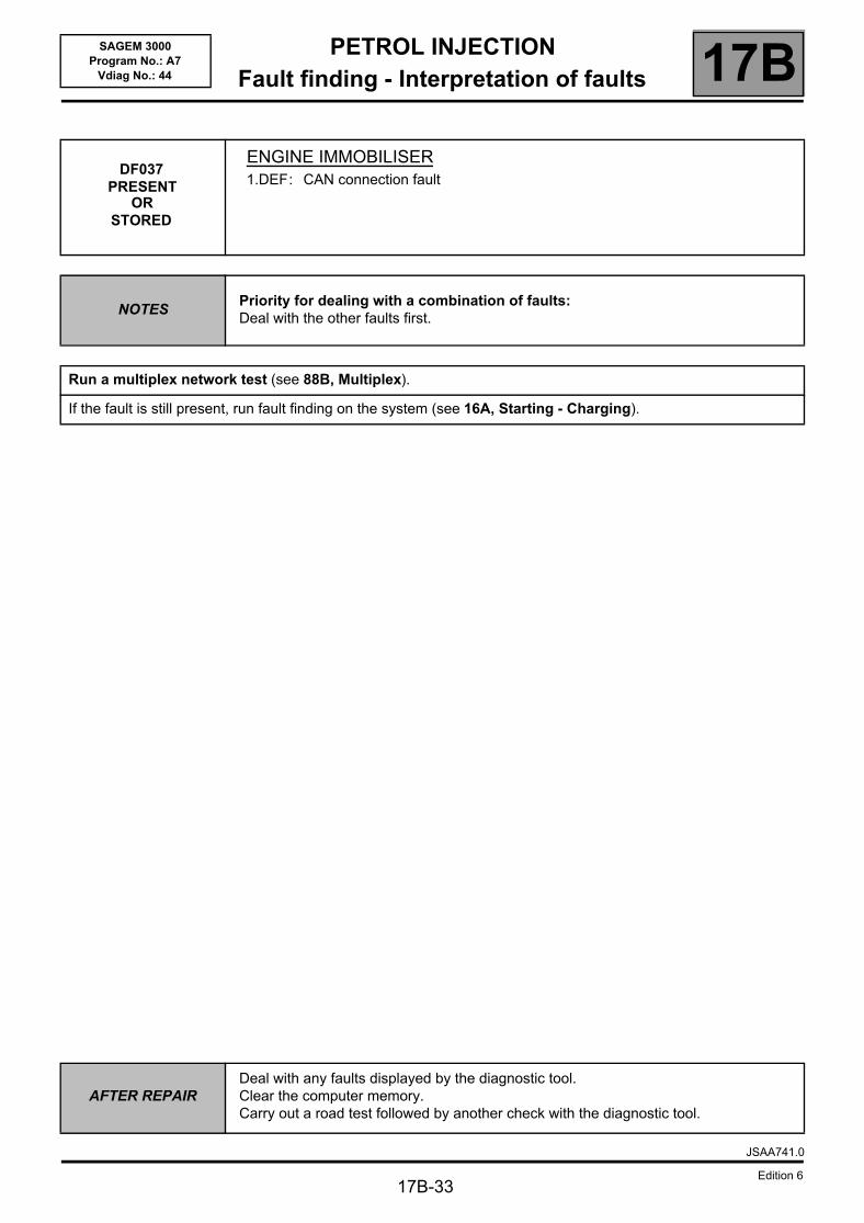
DF037PRESENT
ORSTORED
ENGINE IMMOBILISER1.DEF: CAN connection fault
NOTESPriority for dealing with a combination of faults:Deal with the other faults first.
Run a multiplex network test (see 88B, Multiplex).
If the fault is still present, run fault finding on the system (see 16A, Starting - Charging).
AFTER REPAIRDeal with any faults displayed by the diagnostic tool.Clear the computer memory.Carry out a road test followed by another check with the diagnostic tool.
JSAA741.0
Edition 6
PETROL INJECTIONFault finding - Interpretation of faults 17B
17B-34
SAGEM 3000Program No.: A7
Vdiag No.: 44
DF038PRESENT
COMPUTER1.DEF: internal electronic fault
NOTES
Priority for dealing with a combination of faults:Deal with the other faults first.
Special note:– Throttle valve defect mode types 1 to 6.
Contact Techline.
AFTER REPAIRDeal with any faults displayed by the diagnostic tool.Clear the computer memory.Carry out a road test followed by another check with the diagnostic tool.
JSAA741.0
Edition 6
PETROL INJECTIONFault finding - Interpretation of faults 17B
17B-35
SAGEM 3000Program No.: A7
Vdiag No.: 44
DF046PRESENT
ORSTORED
BATTERY VOLTAGE1.DEF: open circuit or short circuit
NOTES
Priority for dealing with a combination of faults:Apply the procedure for dealing with fault DF084 Actuators relay control circuit first if it is present or stored.
Conditions for applying the fault finding procedure to stored faults:The fault is declared as present at an engine speed above 2000 rpm.
Special note:– Throttle valve defect mode types 1, 2 and 6.
Disconnect the battery and the injection computer.Check the cleanliness and condition of the computer connections.Repair if necessary.
Disconnect the connector marked PPM1 from the Protection and Switching Unit.Check the cleanliness and condition of the connections.Repair if necessary.
Using the Universal bornier, check for continuity on the following connection:Computer, connector B, track M2 Protection and Switching Unit connector PPM1 track 1
Repair if necessary.
Carry out fault finding on the Protection and Switching Unit (the Protection and Switching Unit powers the injection system).
– clean the battery terminals and all connections to the + and the Earth.– check the battery voltage.– check the charging circuit (see MR 364 Mechanical, 16A, Starting - Charging). Repair or replace the faulty components, if necessary.
AFTER REPAIRDeal with any faults detected by the diagnostic tool.Clear the computer memory.Carry out a road test followed by another check with the diagnostic tool.
JSAA741.0
Edition 6
PETROL INJECTIONFault finding - Interpretation of faults 17B
17B-36
SAGEM 3000Program No.: A7
Vdiag No.: 44
DF049 PRESENT
REFRIGERANT SENSOR CIRCUIT1.DEF: voltage outside tolerance range
NOTESPriority for dealing with a combination of faults:Deal with DF012 Sensor feed voltage no. 2 as a priority if it is present or stored.
Check the cleanliness and condition of the manifold pressure sensor and its connections.
Disconnect the battery and the injection computer.Check the cleanliness and condition of the connections.Using the Universal bornier, check the insulation and continuity of the following connections:
Computer, connector B, track J2 Track B of the refrigerant sensorComputer, connector B, track J3 Track C of the refrigerant sensorComputer, connector B, track K2 Track A of the refrigerant sensor
Repair if necessary.
If the fault is still present, deal with the other faults, then proceed to the conformity check.
AFTER REPAIRDeal with any faults displayed by the diagnostic tool.Clear the computer memory.Carry out a road test followed by another check with the diagnostic tool.
JSAA741.0
Edition 6
PETROL INJECTIONFault finding - Interpretation of faults 17B
17B-37
SAGEM 3000Program No.: A7
Vdiag No.: 44
DF054PRESENT
ORSTORED
TURBOCHARGING SOLENOID VALVE CONTROL CIRCUITCO : open circuitCC.0 : short circuit to earthCC.1 : short circuit to + 12 V
NOTES
Conditions for applying the fault finding procedure to stored faults:The fault is declared present after the engine has been running or started at an engine speed above 600 rpm.
Special note:– OBD warning light illuminated,– Throttle valve defect mode type 6.
Check the cleanliness the condition and the assembly of the turbocharging pressure sensor.Repair if necessary.
If the fault is still present, manipulate the harness so that the status changes (present ⇒ stored).Look for possible damage to the harness, check the condition and connection of the injection computer and turbocharging pressure sensor connectors.Repair if necessary.
If the fault is still present, check for the + 12 V on track 2 of the turbocharging solenoid valve.If the + 12 V is not present, check the following connection for insulation, continuity and the absence of interference resistance:
Turbocharging solenoid valve track 2 track 2 of connector PPM1 on the Protection and switching unit
Repair if necessary.
If the fault is still present, disconnect the battery and the injection computer.Check the insulation, continuity and the absence of interference resistance on the following connection:
Computer, connector C, track G4 Track 1 of the turbocharging solenoid valveRepair if necessary.
If the fault is still present, measure the resistance of the turbocharging solenoid valve between tracks 1 and 2.Replace the turbocharging solenoid valve if resistance is not: 10 kΩΩΩΩ no load
5 kΩΩΩΩ full load
If the fault is still present, deal with the other faults, then proceed to the conformity check.
AFTER REPAIRFollow the instructions to confirm repair.Deal with any other faults.Clear the stored faults.
JSAA741.0
Edition 6
PETROL INJECTIONFault finding - Interpretation of faults 17B
17B-38
SAGEM 3000Program No.: A7
Vdiag No.: 44
DF059 PRESENT
OR STORED
COMBUSTION MISFIRES ON CYLINDER 11.DEF: destructive misfiring2.DEF: pollutant misfiring
NOTES
Priority for dealing with a combination of faults:– ignition: DF072, DF073, DF074 and DF075.– fuel supply system: DF026, DF027, DF028, DF029 and DF085.– engine flywheel signal: DF005 and DF125.Check whether other cylinders have misfiring faults before starting the following fault finding procedure.
Conditions for applying the fault finding procedure to stored faults:The fault appears under the following conditions:– there must be no further electrical faults,– programming must be carried out,– engine warm (min 75°°°°),– idling with all the electrical consumers activated for 15 minutes.
Special note:– OBD warning light comes on.
Misfiring on cylinder 1 only
Combustion misfires in cylinders 1 and 4 (see DF059 Combustion misfires in cylinder 1 and DF062 Combustion misfires in cylinder 4)
The fault is probably due to a component that can only affect this cylinder:– check the cylinder 1 injector,– check the condition and conformity of the spark plugs,– check the cylinder 1 pencil coil.If everything is in order, check the same components on cylinder 4 (to cover a possible cylinder recognition error).
The fault is probably due to a component that affects a pair of cylinders:– check the relevant ignition coil circuit (apply the fault finding procedure DF720 Ignition coil
circuit 1 or DF075 Ignition coil circuit 4),– check the condition and conformity of the spark plugs.
AFTER REPAIR
Ensure that all the faults have been dealt with.Clear the stored faults. Do not clear the programming.To check that the system has been properly repaired:– there must be no further electrical faults,– programming has been carried out,– engine hot (minimum 75 °°°°C),– running at idle speed with all electrical consumers drawing power for 15 minutes.If the fault is still present, continue the fault finding procedure.– carry out catalytic converter fault finding through the appropriate After-Sales service.
JSAA741.0
Edition 6

PETROL INJECTIONFault finding - Interpretation of faults 17B
17B-39
SAGEM 3000Program No.: A7
Vdiag No.: 44
DF059
CONTINUED
Combustion misfires on all four cylinders (see DF060, DF061 and DF062)
The fault is probably due to a component affecting all the cylinders:– check that the correct fuel is being used,– check the condition and conformity of the spark plugs.
If the fault is still present, carry out the following checks:– check the flywheel sensor,– check the condition and cleanliness of the flywheel,– check the flywheel sensor mounting,– check the sensor/flywheel air gap,– check the cylinder compressions,– check the entire petrol supply system (see MR 364 Mechanical, 13A, Fuel supply),– check the entire ignition system (see MR 364, Mechanics, 17A, Ignition),– check the hydraulic tappets if there is camshaft noise (see MR 364 Mechanics, 11A, Top and front of engine).
If the fault is still present, deal with the other faults, then proceed to the conformity check.
AFTER REPAIR
Ensure that all the faults have been dealt with.Clear the stored faults. Do not clear the programming.To check that the system has been properly repaired:– there must be no further electrical faults,– programming has been carried out,– engine hot (minimum 75 °°°°C),– running at idle speed with all electrical consumers drawing power for 15 minutes.If the fault is still present, continue the fault finding procedure.– carry out catalytic converter fault finding through the appropriate After-Sales service.
JSAA741.0
Edition 6
PETROL INJECTIONFault finding - Interpretation of faults 17B
17B-40
SAGEM 3000Program No.: A7
Vdiag No.: 44
DF060PRESENT
ORSTORED
COMBUSTION MISFIRES ON CYLINDER 21.DEF: destructive misfiring2.DEF: pollutant misfiring
NOTES
Priority for dealing with a combination of faults:– ignition: DF072, DF073, DF074 and DF075.– fuel supply system: DF026, DF027, DF028, DF029 and DF085.– engine flywheel signal: DF005 and DF125.Check whether other cylinders have misfiring faults before starting the following fault finding procedure.
Conditions for applying the fault finding procedure to stored faults:The fault appears under the following conditions:– there must be no further electrical faults,– programming must be carried out,– engine warm (min 75 °°°°C),– idling with all the electrical consumers activated for 15 minutes.
Special note:– OBD warning light comes on.
Misfiring on cylinder 2 only
Misfire on cylinders 2 and 3 (see DF060 Misfire on cylinder 2 and DF061 Misfire on cylinder 3)
The fault is probably due to a component that can only affect this cylinder:– check the cylinder 2 injector,– check the condition and conformity of the spark plugs,– check the cylinder 2 pencil coil.If everything is in order, check the same components on cylinder 3 (to cover a possible cylinder recognition error).
The fault is probably due to a component that affects a pair of cylinders:– check the relevant ignition coil circuit (apply the fault finding procedure
DF073 Ignition coil circuit 2 or DF074 Ignition coil circuit 3),– check the condition and conformity of the spark plugs.
AFTER REPAIR
Ensure that all the faults have been dealt with.Clear the stored faults. Do not clear the programming.To check that the system has been properly repaired:– there must be no further electrical faults,– programming has been carried out,– engine hot (minimum 75 °°°°C),– running at idle speed with all electrical consumers drawing power for 15 minutes.If the fault is still present, continue the fault finding procedure.– carry out catalytic converter fault finding through the appropriate After-Sales service.
JSAA741.0
Edition 6
PETROL INJECTIONFault finding - Interpretation of faults 17B
17B-41
SAGEM 3000Program No.: A7
Vdiag No.: 44
DF060
CONTINUED
Combustion misfires on all four cylinders (see DF060, DF061 and DF062)
The fault is probably due to a component affecting all the cylinders:– check that the correct fuel is being used,– check the condition and conformity of the spark plugs.
If the fault is still present, carry out the following checks:– check the flywheel sensor,– check the condition and cleanliness of the flywheel,– check the flywheel sensor mounting,– check the flywheel/sensor air gap,– check the cylinder compressions,– check the entire petrol supply system (see MR 364 Mechanical, 13A, Fuel supply),– check the entire ignition system (see MR 364, Mechanics, 17A, Ignition),– check the hydraulic tappets if there is camshaft noise (see MR 364 Mechanics, 11A, Top and front of engine).
If the fault is still present, deal with the other faults, then proceed to the conformity check.
AFTER REPAIR
Ensure that all the faults have been dealt with.Clear the stored faults. Do not clear the programming.To check that the system has been properly repaired:– there must be no further electrical faults,– programming has been carried out,– engine hot (minimum 75 °°°°C),– running at idle speed with all electrical consumers drawing power for 15 minutes.If the fault is still present, continue the fault finding procedure.– carry out catalytic converter fault finding through the appropriate After-Sales service.
JSAA741.0
Edition 6

PETROL INJECTIONFault finding - Interpretation of faults 17B
17B-42
SAGEM 3000Program No.: A7
Vdiag No.: 44
DF061PRESENT
OR STORED
COMBUSTION MISFIRES ON CYLINDER 31.DEF: destructive misfiring2.DEF: pollutant misfiring
NOTES
Priority for dealing with a combination of faults:– ignition: DF072, DF073, DF074 and DF075.– fuel supply system: DF026, DF027, DF028, DF029 and DF085.– engine flywheel signal: DF005 and DF125.Check whether other cylinders have misfiring faults before starting the following fault finding procedure.
Conditions for applying the fault finding procedure to stored faults:The fault appears under the following conditions:– there must be no further electrical faults,– programming must be carried out,– engine warm (min 75 °°°°C),– idling with all the electrical consumers activated for 15 minutes.
Special note:– OBD warning light comes on.
Misfiring on cylinder 3 only
Combustion misfires in cylinders 2 and 3 (see DF060 Combustion misfires on cylinder 2 and DF061 Combustion misfires on cylinder 3)
The fault is probably due to a component that can only affect this cylinder:– check the cylinder 3 injector,– check the condition and conformity of the spark plugs,– check the cylinder 3 pencil coil.If everything is in order, check the same components on cylinder 2 (to cover a possible cylinder recognition error).
The fault is probably due to a component that affects a pair of cylinders:– check the relevant ignition coil circuit (apply the fault finding procedure DF073 Ignition coil
circuit 2 or DF074 Ignition coil circuit 3),– check the condition and conformity of the spark plugs.
AFTER REPAIR
Ensure that all the faults have been dealt with.Clear the stored faults. Do not clear the programming.To check that the system has been properly repaired:– there must be no further electrical faults,– programming has been carried out,– engine hot (minimum 75 °°°°C),– running at idle speed with all electrical consumers drawing power for 15 minutes.If the fault is still present, continue the fault finding procedure.– carry out catalytic converter fault finding through the appropriate After-Sales service.
JSAA741.0
Edition 6
PETROL INJECTIONFault finding - Interpretation of faults 17B
17B-43
SAGEM 3000Program No.: A7
Vdiag No.: 44
DF061
CONTINUED
Combustion misfires on all four cylinders (see DF060, DF061 and DF062)
The fault is probably due to a component affecting all the cylinders:– check that the correct fuel is being used,– check the condition and conformity of the spark plugs.
If the fault is still present, carry out the following checks:– check the flywheel sensor,– check the condition and cleanliness of the flywheel,– check the flywheel sensor mounting,– check the flywheel/sensor air gap,– check the cylinder compressions,– check the entire petrol supply system (see MR 364 Mechanical, 13A, Fuel supply),– check the entire ignition system (see MR 364, Mechanics, 17A, Ignition),– check the hydraulic tappets if there is camshaft noise (see MR 364 Mechanics, 11A, Top and front of engine).
If the fault is still present, deal with the other faults, then proceed to the conformity check.
AFTER REPAIR
Ensure that all the faults have been dealt with.Clear the stored faults. Do not clear the programming.To check that the system has been properly repaired:– there must be no further electrical faults,– programming has been carried out,– engine hot (minimum 75 °°°°C),– running at idle speed with all electrical consumers drawing power for 15 minutes.If the fault is still present, continue the fault finding procedure.– carry out catalytic converter fault finding through the appropriate After-Sales service.
JSAA741.0
Edition 6
PETROL INJECTIONFault finding - Interpretation of faults 17B
17B-44
SAGEM 3000Program No.: A7
Vdiag No.: 44
DF062 PRESENT
OR STORED
COMBUSTION MISFIRES ON CYLINDER 41.DEF: destructive misfiring2.DEF: pollutant misfiring
NOTES
Priority for dealing with a combination of faults:– ignition: DF072, DF073, DF074 and DF075.– fuel supply system: DF026, DF027, DF028, DF029 and DF085.– engine flywheel signal: DF005 and DF125.Check whether other cylinders have misfiring faults before starting the following fault finding procedure.
Conditions for applying the fault finding procedure to stored faults:The fault appears under the following conditions:– there must be no further electrical faults,– programming must be carried out,– engine warm (min 75 °°°°C),– idling with all the electrical consumers activated for 15 minutes.
Special note:– OBD warning light comes on.
Misfiring on cylinder 4 only
Combustion misfires in cylinders 1 and 4 (see DF059 Combustion misfires in cylinder 1 and DF062 Combustion misfires in cylinder 4)
The fault is probably due to a component that can only affect this cylinder:– check the cylinder 4 injector,– check the condition and conformity of the spark plugs,– check the pencil coil of cylinder 4.If everything is in order, check the same components on cylinder 1 (to cover a possible cylinder recognition error).
The fault is probably due to a component that affects a pair of cylinders:– check the relevant ignition coil circuit (apply the fault finding procedure DF072 Ignition coil
circuit 1 or DF075 Ignition coil circuit 4),– check the condition and conformity of the spark plugs.
AFTER REPAIR
Ensure that all the faults have been dealt with.Clear the stored faults. Do not clear the programming.To check that the system has been properly repaired:– there must be no further electrical faults,– programming has been carried out,– engine hot (minimum 75 °°°°C),– running at idle speed with all electrical consumers drawing power for 15 minutes.If the fault is still present, continue the fault finding procedure.– carry out catalytic converter fault finding through the appropriate After-Sales service.
JSAA741.0
Edition 6

PETROL INJECTIONFault finding - Interpretation of faults 17B
17B-45
SAGEM 3000Program No.: A7
Vdiag No.: 44
DF062
CONTINUED
Combustion misfires on all four cylinders (see DF060, DF061 and DF062)
The fault is probably due to a component affecting all the cylinders:– check that the correct fuel is being used,– check the condition and conformity of the spark plugs.
If the fault is still present, carry out the following checks:– check the flywheel sensor,– check the condition and cleanliness of the flywheel,– check the flywheel sensor mounting,– check the flywheel/sensor air gap,– check the cylinder compressions,– check the entire petrol supply system (see MR 364 Mechanical, 13A, Fuel supply),– check the entire ignition system (see MR 364, Mechanics, 17A, Ignition),– check the hydraulic tappets if there is camshaft noise (see MR 364 Mechanics, 11A, Top and front of engine).
If the fault is still present, deal with the other faults, then proceed to the conformity check.
AFTER REPAIR
Ensure that all the faults have been dealt with.Clear the stored faults. Do not clear the programming.To check that the system has been properly repaired:– there must be no further electrical faults,– programming has been carried out,– engine hot (minimum 75 °°°°C),– running at idle speed with all electrical consumers drawing power for 15 minutes.If the fault is still present, continue the fault finding procedure.– carry out catalytic converter fault finding through the appropriate After-Sales service.
JSAA741.0
Edition 6
PETROL INJECTIONFault finding - Interpretation of faults 17B
17B-46
SAGEM 3000Program No.: A7
Vdiag No.: 44
DF065 PRESENT
ORSTORED
COMBUSTION MISFIRES1.DEF: destructive misfiring2.DEF: pollutant misfiring
NOTES
Priority for dealing with a combination of faults:– ignition: DF072, DF073, DF074 and DF075.– fuel supply system: DF026, DF027, DF028, DF029 and DF085.– engine flywheel signal: DF005 and DF125.– cylinder misfires: DF059, DF060, DF061 and DF062.
Conditions for applying the fault finding procedure to stored faults:The fault appears under the following conditions:– there must be no further electrical faults,– programming must be carried out,– engine warm (min 75 °°°°C),– idling with all the electrical consumers activated for 15 minutes.
Special note:– OBD warning light comes on.
Check the injectors.Check the condition and conformity of the spark plugs.Check the ignition pencil coils.Check that the fuel is correct.
If the fault is still present, carry out the following checks:– check the flywheel sensor,– check the condition and cleanliness of the flywheel,– check the flywheel sensor mounting,– check the flywheel/sensor air gap,– check the cylinder compressions,– check the entire petrol supply system (see MR 364 Mechanical, 13A, Fuel supply),– check the entire ignition system (see MR 364, Mechanics, 17A, Ignition),– check the hydraulic tappets if there is camshaft noise (see MR 364 Mechanics, 11A, Top and front of engine).
If the fault is still present, deal with the other faults, then proceed to the conformity check.
AFTER REPAIRFollow the instructions to confirm repair.Deal with any other faults.Clear the stored faults.
JSAA741.0
Edition 6
PETROL INJECTIONFault finding - Interpretation of faults 17B
17B-47
SAGEM 3000Program No.: A7
Vdiag No.: 44
DF072PRESENT
ORSTORED
CYLINDER 1 IGNITION COIL CIRCUITCO.0 : open circuit or short circuit to earthCC.1 : short circuit to + 12 V
NOTES
Priority for dealing with a combination of faults:Deal with faults DF046 Battery voltage, DF084 Actuator relay control circuit or DF085 Fuel pump relay control circuit first if they are present or stored.If the DF075 Cylinder 4 ignition coil circuit fault is also present or stored, deal with it first.
Conditions for applying the fault finding procedure to stored faults:The fault is declared present after the starter has been in operation for 10 seconds or after the engine has been running for 10 seconds.
Special note:– OBD warning light comes on.
Disconnect the cylinder 1 pencil coil connector.Check the cleanliness and condition of the pencil coil and its connections.Check that the fuel is correct.
Measure the primary and secondary resistance of the cylinder 1 pencil coil.Replace the cylinder 1 coil if the primary resistance is not 0.58 ΩΩΩΩ ±±±± 10% or the secondary resistance is not 10.9 kΩΩΩΩ ±±±± 15%.
Disconnect the battery and the injection computer.Check the cleanliness and condition of the connections.Using the universal bornier, check for insulation and continuity on the following connections:
Computer, connector C, track M4 Track 2 of Coil 1 Coil 4 track 2 Track 1 of Coil 1
Repair if necessary.
If the fault is still present, replace the defective pencil coil.
If the fault is still present, deal with the other faults, then proceed to the conformity check.
AFTER REPAIRFollow the instructions to confirm repair.Deal with any other faults.Clear the fault memory.
JSAA741.0
Edition 6
PETROL INJECTIONFault finding - Interpretation of faults 17B
17B-48
SAGEM 3000Program No.: A7
Vdiag No.: 44
DF073PRESENT
ORSTORED
CYLINDER 2 IGNITION COIL CIRCUITCO.0 : open circuit or short circuit to earthCC.1 : short circuit to + 12 V
NOTES
Priority for dealing with a combination of faults:Deal with faults DF046 Battery voltage, DF084 Actuator relay control circuit or DF085 Fuel pump relay control circuit first if they are present or stored.If the fault DF074 Cylinder ignition coil circuit 3 is also present or stored, deal with it first.
Conditions for applying the fault finding procedure to stored faults:The fault is declared present after the starter has been in operation for 10 seconds or after the engine has been running for 10 seconds.
Special note:– OBD warning light comes on.
Disconnect the cylinder 2 pencil coil connector.Check the cleanliness and condition of the pencil coil and its connections. Check that the fuel is correct.
Measure the primary and secondary resistance of the cylinder 2 pencil coil.Replace the cylinder 2 coil if the primary resistance is not 0.58 ΩΩΩΩ ±±±± 10% or the secondary resistance is not 10.9 kΩΩΩΩ ±±±± 15%.
Disconnect the battery and the injection computer.Check the cleanliness and condition of the connections.Using the universal bornier, check for insulation and continuity on the following connections:
Computer, connector C, track M3 Track 2 of Coil 2Coil 3 track 2 Track 1 of Coil 2
Repair if necessary.
If the fault is still present, replace the defective pencil coil.
If the fault is still present, deal with the other faults, then proceed to the conformity check.
AFTER REPAIRFollow the instructions to confirm repair.Deal with any other faults.Clear the fault memory.
JSAA741.0
Edition 6
PETROL INJECTIONFault finding - Interpretation of faults 17B
17B-49
SAGEM 3000Program No.: A7
Vdiag No.: 44
DF074 PRESENT
OR STORED
CYLINDER 3 IGNITION COIL CIRCUITCO.0 : open circuit or short circuit to earthCC.1 : short circuit to + 12 V
NOTES
Priority for dealing with a combination of faults:Deal with faults DF046 Battery voltage, DF084 Actuator relay control circuit or DF085 Fuel pump relay control circuit first if they are present or stored.
Conditions for applying the fault finding procedure to stored faults:The fault is declared present after the starter has been in operation for 10 seconds or after the engine has been running for 10 seconds.
Special note:– OBD warning light comes on.
Disconnect the pencil coil connector on cylinder 3.Check the cleanliness and condition of the pencil coil and its connections. Check that the fuel is correct.
Measure the primary and secondary resistance of the cylinder 3 pencil coil.Replace the cylinder 3 coil if the primary resistance is not 0.58 ΩΩΩΩ ±±±± 10% or the secondary resistance is not 10.9 kΩΩΩΩ ±±±± 15%.
Disconnect the battery and the injection computer.Check the cleanliness and condition of the connections.Using the universal bornier, check for insulation and continuity on the following connections:
Computer, connector C, track M3 Track 2 of Coil 2Coil 3 track 2 Track 1 of Coil 2
Repair if necessary.
Check for the + 12 V feed on track 1 of the cylinder 3 pencil coil connector with the ignition on.If + 12 V is not present:– disconnect the battery,– disconnect the connector marked PPM2 in the Protection and Switching Unit,– check the cleanliness and condition of the connections,– using the Universal bornier, check for continuity on the following connection:
Protection and Switching Unit connector PPM1 track 8 track 1 of the pencil coil for cylinder 3Repair if necessary.
Reconnect the Protection and Switching Unit connector and reconnect the battery.If the + 12 V feed on track 1 is still not present on the cylinder 3 injector connector with the ignition on, there is a fault with the Protection and Switching Unit.Contact Techline.
If the fault is still present, replace the defective pencil coil.
If the fault is still present, deal with the other faults, then proceed to the conformity check.
AFTER REPAIRFollow the instructions to confirm repair.Deal with any other faults.Clear the fault memory.
JSAA741.0
Edition 6
PETROL INJECTIONFault finding - Interpretation of faults 17B
17B-50
SAGEM 3000Program No.: A7
Vdiag No.: 44
DF075PRESENT
ORSTORED
CYLINDER 4 IGNITION COIL CIRCUITCO.0 : open circuit or short circuit to earthCC.1 : short circuit to + 12 V
NOTES
Priority for dealing with a combination of faults:Deal with faults DF046 Battery voltage, DF084 Actuator relay control circuit or DF085 Fuel pump relay control circuit first if they are present or stored.
Conditions for applying the fault finding procedure to stored faults:The fault is declared present after the starter has been in operation for 10 seconds or after the engine has been running for 10 seconds.
Special note:– OBD warning light comes on.
Disconnect the cylinder 4 pencil coil connector.Check the cleanliness and condition of the pencil coil and its connections. check that the correct fuel is being used,
Measure the primary and secondary resistance of the cylinder 4 pencil coil.Replace the cylinder 4 coil if the primary resistance is not 0.58 ΩΩΩΩ ±±±± 10% or the secondary resistance is not 10.9 kΩΩΩΩ ±±±± 15%.
Disconnect the battery and the injection computer.Check the cleanliness and condition of the connections.Using the universal bornier, check for insulation and continuity on the following connections:
Computer, connector C, track M4 track 2 of Coil 1Coil 4 track 2 track 1 of Coil 1
Repair if necessary.
Check for the + 12 V feed on track 1 of the cylinder 4 pencil coil connector with the ignition on.If + 12 V is not present:– disconnect the battery,– disconnect the connector marked PPM2 in the Protection and Switching Unit,– check the cleanliness and condition of the connections,– using the Universal bornier, check for continuity on the following connection:
Protection and Switching Unit connector PPM1 track 8 track 1 of the pencil coil for cylinder 4Repair if necessary.
Reconnect the Protection and Switching Unit connector and reconnect the battery.If the + 12 V feed on track1 is still not present on the cylinder 4 injector connector with the ignition on, there is a fault with the Protection and Switching Unit.Contact Techline.
If the fault is still present, replace the defective pencil coil.
If the fault is still present, deal with the other faults, then proceed to the conformity check.
AFTER REPAIRFollow the instructions to confirm repair.Deal with any other faults.Clear the stored faults.
JSAA741.0
Edition 6
PETROL INJECTIONFault finding - Interpretation of faults 17B
17B-51
SAGEM 3000Program No.: A7
Vdiag No.: 44
DF078PRESENT
ORSTORED
MOTORISED THROTTLE CONTROL CIRCUITCC.1 : short circuit to + 12 V1.DEF: motorised throttle general control fault
WARNINGNever drive the vehicle without having checked that there are no faults involving the throttle valve.
NOTES
Priority for dealing with a combination of faults:If faults DF095 Throttle potentiometer circuit gang 1 or DF096 Throttle potentiometer circuit gang 2 are present, deal with these first.
Conditions for applying the fault finding procedure to stored faults:The fault appears after:– a change in engine speed,– the air temperature must be between 5 °°°°C and 105 °°°°C inclusive.
Special note:– level 1 fault warning light illuminated,– throttle valve defect mode types 1, 2 and 6.
Check the cleanliness and condition of the throttle valve and its connections.
Manually check that the throttle rotates properly.
Disconnect the battery and the injection computer.Check the cleanliness and condition of the connections.Using the universal bornier, check for insulation and continuity on the following connections:
Computer, connector B, track M3 Track 4 of the motorised throttleComputer, connector B, track M4 Track 3 of the motorised throttleComputer, connector B, track G4 Track 1 of the motorised throttle
Repair if necessary.
Measure the resistance of the throttle motor between tracks M3 and M4 of the computer.Replace the throttle valve if the resistance is not 1.57 ΩΩΩΩ at 23 °°°°C.
If the fault is still present, deal with the other faults, then proceed to the conformity check.
AFTER REPAIRDeal with any faults displayed by the diagnostic tool.Clear the computer memory.Carry out a road test followed by another check with the diagnostic tool.
JSAA741.0
Edition 6
PETROL INJECTIONFault finding - Interpretation of faults 17B
17B-52
SAGEM 3000Program No.: A7
Vdiag No.: 44
DF079 PRESENT
ORSTORED
MOTORISED THROTTLE VALVE SERVO CONTROL1.DEF: motorised throttle stop search fault2.DEF: motorised throttle rest position programming error3.DEF: motorised throttle automatic control fault4.DEF: the position memory function does not work5.DEF: when the throttle bounces off the lower stop, a relatively large permanent discrepancy can be seen between the set position and actual position of the throttle. The bounce detection is based on this error. The oscillation fault, after N oscillations detected, activates the Limp Home defect mode.6.DEF: when there is a micro-break on gang 1 of the sensor, the voltage delivered is minimal (0V), which broadly corresponds to complete throttle closure. We can then see the gang 1 signal lapse in relation to the gang 2 signal, which remains correct. This lapse speed of one gang in relation to another is used to detect micro-breaks.The micro-break fault does not activate any defect mode or illuminate any warning lights.7.DEF: non-compliance with emission control standards
NOTES
Priority for dealing with a combination of faults:Apply the procedure for dealing with faults DF011 Sensor supply voltage no. 1, DF078 Throttle potentiometer control circuit, DF095 Throttle potentiometer circuit gang 1 and DF096 Throttle potentiometer circuit gang 2 first if they are present or stored.
Conditions for applying the fault finding procedure to stored faults:The fault appears after:– A change in engine speed.– The air temperature must be between 5 °°°°C and 105 °°°°C inclusive.
Special note:If 1.DEF, 2.DEF or 3.DEF:– OBD warning light illuminated,– throttle valve defect mode types 1, 2 and 6.If 4.DEF or 5.DEF:– OBD warning light illuminated,– throttle valve defect mode types 1, 2, 4 and 6.
Check the cleanliness, condition and fitting of the throttle valve.Repair if necessary.
If the fault is still present, manually check that the throttle valve rotates correctly.Repair if necessary.
If the fault is still present, manipulate the harness so that the status changes (present ⇒ stored).Look for possible damage to the harness, check the condition and the connection of the injection computer and motorised throttle valve connectors.Repair if necessary.
JSAA741.0
Edition 6
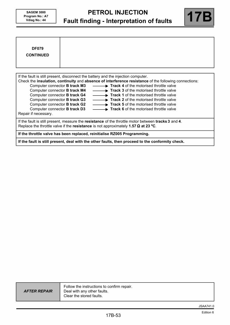
PETROL INJECTIONFault finding - Interpretation of faults 17B
17B-53
SAGEM 3000Program No.: A7
Vdiag No.: 44
DF079
CONTINUED
If the fault is still present, disconnect the battery and the injection computer.Check the insulation, continuity and absence of interference resistance of the following connections:
Computer connector B track M3 Track 4 of the motorised throttle valveComputer connector B track M4 Track 3 of the motorised throttle valveComputer connector B track G4 Track 1 of the motorised throttle valveComputer connector B track G3 Track 2 of the motorised throttle valveComputer connector B track G2 Track 5 of the motorised throttle valveComputer connector B track D3 Track 6 of the motorised throttle valve
Repair if necessary.
If the fault is still present, measure the resistance of the throttle motor between tracks 3 and 4.Replace the throttle valve if the resistance is not approximately 1.57 ΩΩΩΩ at 23 °°°°C.
If the throttle valve has been replaced, reinitialise RZ005 Programming.
If the fault is still present, deal with the other faults, then proceed to the conformity check.
AFTER REPAIRFollow the instructions to confirm repair.Deal with any other faults.Clear the stored faults.
JSAA741.0
Edition 6
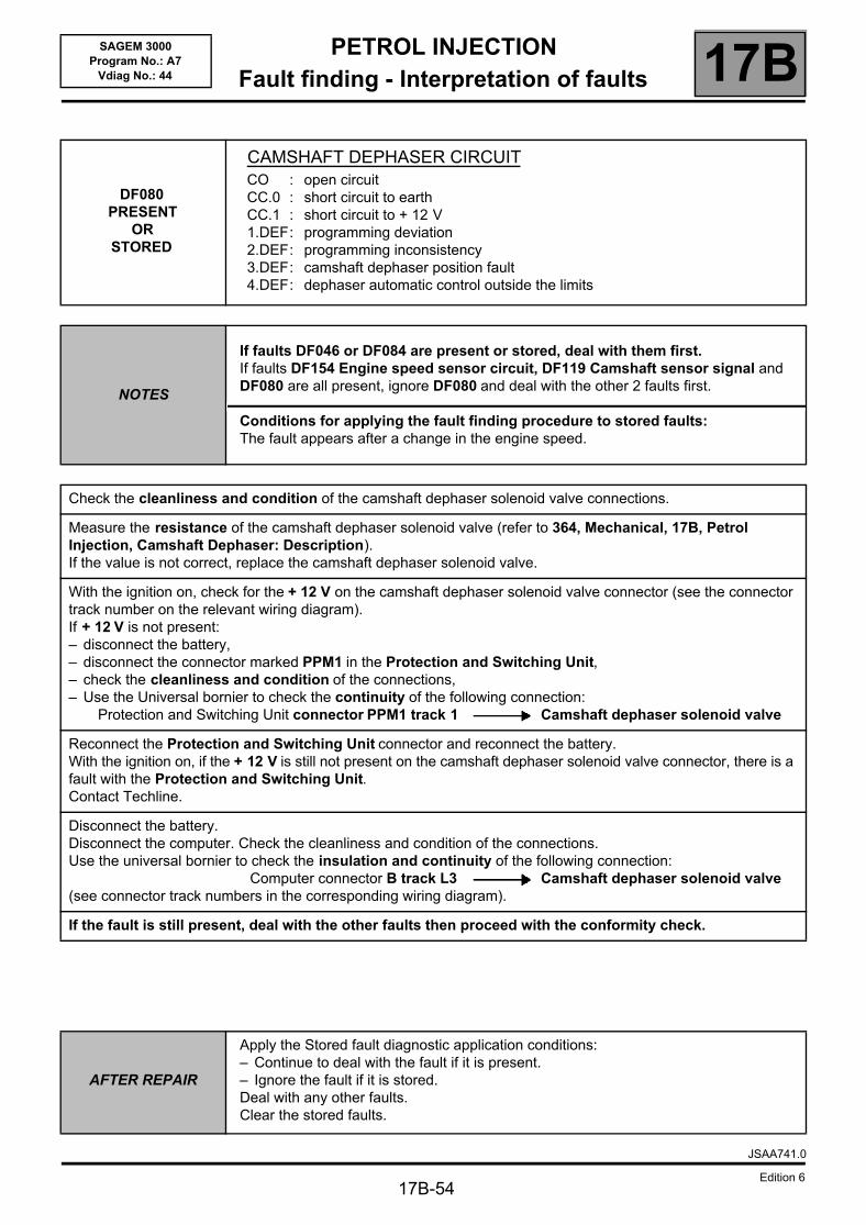
PETROL INJECTIONFault finding - Interpretation of faults 17B
17B-54
SAGEM 3000Program No.: A7
Vdiag No.: 44
DF080PRESENT
ORSTORED
CAMSHAFT DEPHASER CIRCUITCO : open circuitCC.0 : short circuit to earthCC.1 : short circuit to + 12 V1.DEF: programming deviation2.DEF: programming inconsistency3.DEF: camshaft dephaser position fault4.DEF: dephaser automatic control outside the limits
NOTES
If faults DF046 or DF084 are present or stored, deal with them first.If faults DF154 Engine speed sensor circuit, DF119 Camshaft sensor signal and DF080 are all present, ignore DF080 and deal with the other 2 faults first.
Conditions for applying the fault finding procedure to stored faults:The fault appears after a change in the engine speed.
Check the cleanliness and condition of the camshaft dephaser solenoid valve connections.
Measure the resistance of the camshaft dephaser solenoid valve (refer to 364, Mechanical, 17B, Petrol Injection, Camshaft Dephaser: Description).If the value is not correct, replace the camshaft dephaser solenoid valve.
With the ignition on, check for the + 12 V on the camshaft dephaser solenoid valve connector (see the connector track number on the relevant wiring diagram).If + 12 V is not present: – disconnect the battery,– disconnect the connector marked PPM1 in the Protection and Switching Unit,– check the cleanliness and condition of the connections,– Use the Universal bornier to check the continuity of the following connection:
Protection and Switching Unit connector PPM1 track 1 Camshaft dephaser solenoid valve
Reconnect the Protection and Switching Unit connector and reconnect the battery.With the ignition on, if the + 12 V is still not present on the camshaft dephaser solenoid valve connector, there is a fault with the Protection and Switching Unit.Contact Techline.
Disconnect the battery.Disconnect the computer. Check the cleanliness and condition of the connections.Use the universal bornier to check the insulation and continuity of the following connection:
Computer connector B track L3 Camshaft dephaser solenoid valve(see connector track numbers in the corresponding wiring diagram).
If the fault is still present, deal with the other faults then proceed with the conformity check.
AFTER REPAIR
Apply the Stored fault diagnostic application conditions:– Continue to deal with the fault if it is present.– Ignore the fault if it is stored.Deal with any other faults.Clear the stored faults.
JSAA741.0
Edition 6
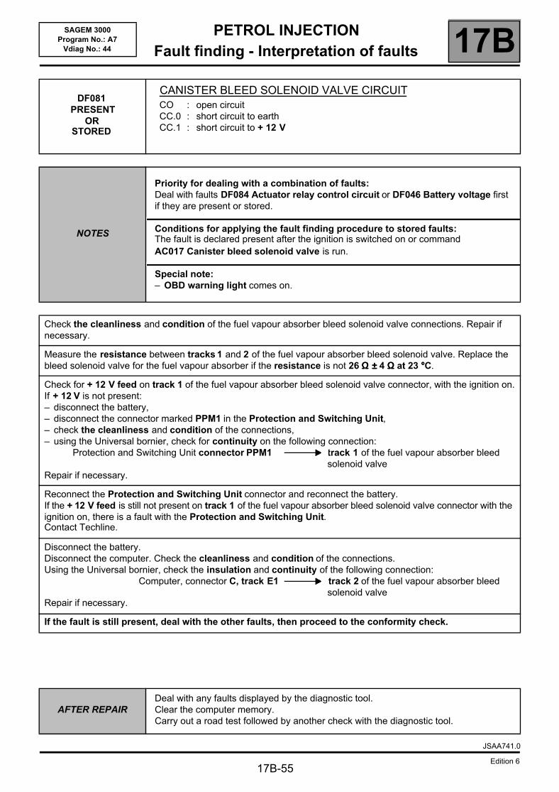
PETROL INJECTIONFault finding - Interpretation of faults 17B
17B-55
SAGEM 3000Program No.: A7
Vdiag No.: 44
DF081 PRESENT
ORSTORED
CANISTER BLEED SOLENOID VALVE CIRCUITCO : open circuitCC.0 : short circuit to earthCC.1 : short circuit to + 12 V
NOTES
Priority for dealing with a combination of faults:Deal with faults DF084 Actuator relay control circuit or DF046 Battery voltage first if they are present or stored.
Conditions for applying the fault finding procedure to stored faults:The fault is declared present after the ignition is switched on or command AC017 Canister bleed solenoid valve is run.
Special note:– OBD warning light comes on.
Check the cleanliness and condition of the fuel vapour absorber bleed solenoid valve connections. Repair if necessary.
Measure the resistance between tracks 1 and 2 of the fuel vapour absorber bleed solenoid valve. Replace the bleed solenoid valve for the fuel vapour absorber if the resistance is not 26 ΩΩΩΩ ±±±± 4 ΩΩΩΩ at 23 °°°°C.
Check for + 12 V feed on track 1 of the fuel vapour absorber bleed solenoid valve connector, with the ignition on.If + 12 V is not present:– disconnect the battery,– disconnect the connector marked PPM1 in the Protection and Switching Unit,– check the cleanliness and condition of the connections,– using the Universal bornier, check for continuity on the following connection:
Protection and Switching Unit connector PPM1 track 1 of the fuel vapour absorber bleed solenoid valve
Repair if necessary.
Reconnect the Protection and Switching Unit connector and reconnect the battery.If the + 12 V feed is still not present on track 1 of the fuel vapour absorber bleed solenoid valve connector with the ignition on, there is a fault with the Protection and Switching Unit.Contact Techline.
Disconnect the battery.Disconnect the computer. Check the cleanliness and condition of the connections.Using the Universal bornier, check the insulation and continuity of the following connection:
Computer, connector C, track E1 track 2 of the fuel vapour absorber bleed solenoid valve
Repair if necessary.
If the fault is still present, deal with the other faults, then proceed to the conformity check.
AFTER REPAIRDeal with any faults displayed by the diagnostic tool.Clear the computer memory.Carry out a road test followed by another check with the diagnostic tool.
JSAA741.0
Edition 6
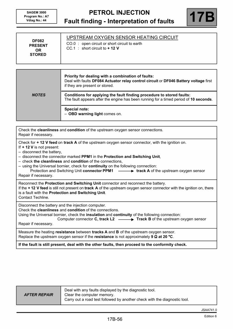
PETROL INJECTIONFault finding - Interpretation of faults 17B
17B-56
SAGEM 3000Program No.: A7
Vdiag No.: 44
DF082PRESENT
OR STORED
UPSTREAM OXYGEN SENSOR HEATING CIRCUITCO.0 : open circuit or short circuit to earthCC.1 : short circuit to + 12 V
NOTES
Priority for dealing with a combination of faults:Deal with faults DF084 Actuator relay control circuit or DF046 Battery voltage first if they are present or stored.
Conditions for applying the fault finding procedure to stored faults:The fault appears after the engine has been running for a timed period of 10 seconds.
Special note:– OBD warning light comes on.
Check the cleanliness and condition of the upstream oxygen sensor connections.Repair if necessary.
Check for + 12 V feed on track A of the upstream oxygen sensor connector, with the ignition on.If + 12 V is not present:– disconnect the battery,– disconnect the connector marked PPM1 in the Protection and Switching Unit,– check the cleanliness and condition of the connections,– using the Universal bornier, check for continuity on the following connection:
Protection and Switching Unit connector PPM1 track A of the upstream oxygen sensorRepair if necessary.
Reconnect the Protection and Switching Unit connector and reconnect the battery.If the + 12 V feed is still not present on track A of the upstream oxygen sensor connector with the ignition on, there is a fault with the Protection and Switching Unit.Contact Techline.
Disconnect the battery and the injection computer.Check the cleanliness and condition of the connections.Using the Universal bornier, check the insulation and continuity of the following connection:
Computer connector C, track L2 Track B of the upstream oxygen sensorRepair if necessary.
Measure the heating resistance between tracks A and B of the upstream oxygen sensor.Replace the upstream oxygen sensor if the resistance is not approximately 9 ΩΩΩΩ at 20 °°°°C.
If the fault is still present, deal with the other faults, then proceed to the conformity check.
AFTER REPAIRDeal with any faults displayed by the diagnostic tool.Clear the computer memory.Carry out a road test followed by another check with the diagnostic tool.
JSAA741.0
Edition 6
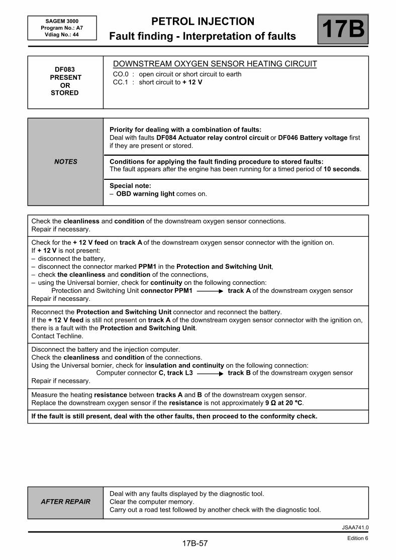
PETROL INJECTIONFault finding - Interpretation of faults 17B
SAGEM 3000Program No.: A7
Vdiag No.: 44
DF083 PRESENT
ORSTORED
DOWNSTREAM OXYGEN SENSOR HEATING CIRCUITCO.0 : open circuit or short circuit to earthCC.1 : short circuit to + 12 V
NOTES
Priority for dealing with a combination of faults:Deal with faults DF084 Actuator relay control circuit or DF046 Battery voltage first if they are present or stored.
Conditions for applying the fault finding procedure to stored faults:The fault appears after the engine has been running for a timed period of 10 seconds.
Special note:– OBD warning light comes on.
Check the cleanliness and condition of the downstream oxygen sensor connections.Repair if necessary.
Check for the + 12 V feed on track A of the downstream oxygen sensor connector with the ignition on.If + 12 V is not present:– disconnect the battery,– disconnect the connector marked PPM1 in the Protection and Switching Unit,– check the cleanliness and condition of the connections,– using the Universal bornier, check for continuity on the following connection:
Protection and Switching Unit connector PPM1 track A of the downstream oxygen sensorRepair if necessary.
Reconnect the Protection and Switching Unit connector and reconnect the battery.If the + 12 V feed is still not present on track A of the downstream oxygen sensor connector with the ignition on, there is a fault with the Protection and Switching Unit.Contact Techline.
Disconnect the battery and the injection computer.Check the cleanliness and condition of the connections.Using the Universal bornier, check for insulation and continuity on the following connection:
Computer connector C, track L3 track B of the downstream oxygen sensorRepair if necessary.
Measure the heating resistance between tracks A and B of the downstream oxygen sensor.Replace the downstream oxygen sensor if the resistance is not approximately 9 ΩΩΩΩ at 20 °°°°C.
If the fault is still present, deal with the other faults, then proceed to the conformity check.
AFTER REPAIRDeal with any faults displayed by the diagnostic tool.Clear the computer memory.Carry out a road test followed by another check with the diagnostic tool.
JSAA741.0
Edition 617B-57
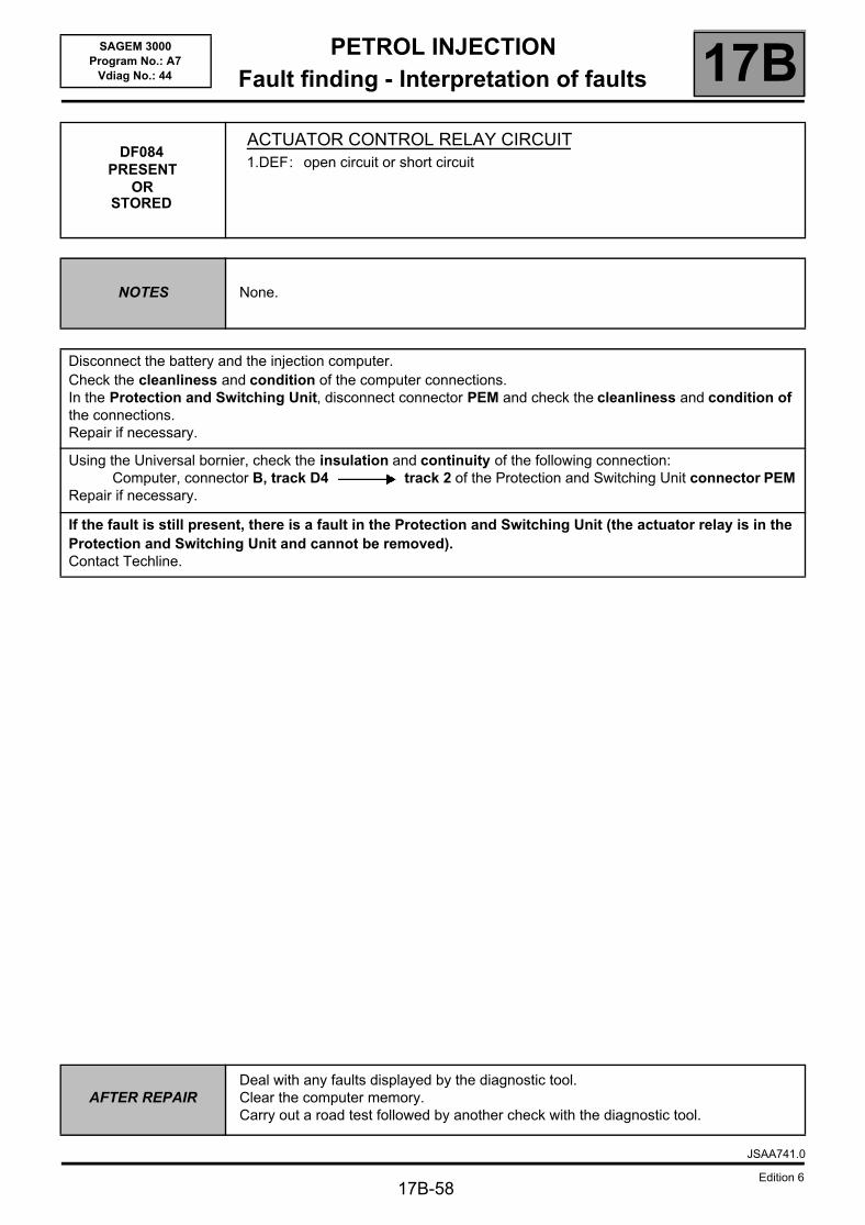
PETROL INJECTIONFault finding - Interpretation of faults 17B
17B-58
SAGEM 3000Program No.: A7
Vdiag No.: 44
DF084PRESENT
ORSTORED
ACTUATOR CONTROL RELAY CIRCUIT1.DEF: open circuit or short circuit
NOTES None.
Disconnect the battery and the injection computer.Check the cleanliness and condition of the computer connections.In the Protection and Switching Unit, disconnect connector PEM and check the cleanliness and condition of the connections.Repair if necessary.
Using the Universal bornier, check the insulation and continuity of the following connection:Computer, connector B, track D4 track 2 of the Protection and Switching Unit connector PEM
Repair if necessary.
If the fault is still present, there is a fault in the Protection and Switching Unit (the actuator relay is in the Protection and Switching Unit and cannot be removed).Contact Techline.
AFTER REPAIRDeal with any faults displayed by the diagnostic tool.Clear the computer memory.Carry out a road test followed by another check with the diagnostic tool.
JSAA741.0
Edition 6
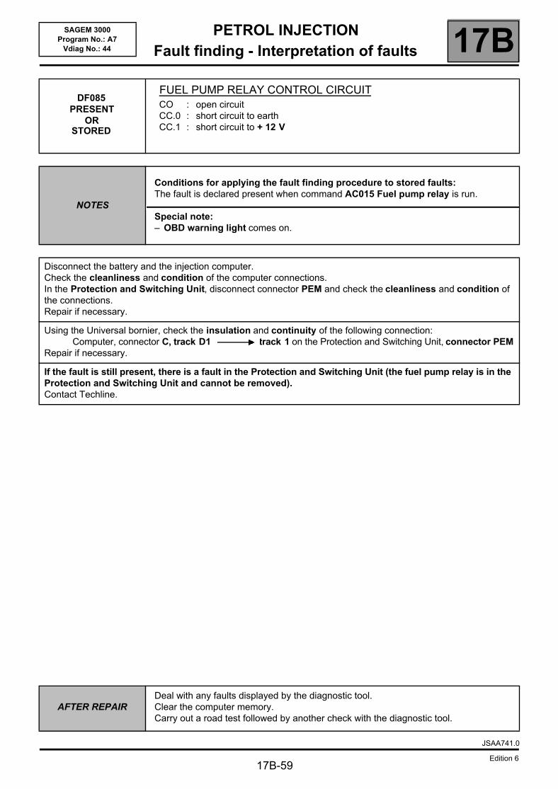
PETROL INJECTIONFault finding - Interpretation of faults 17B
17B-59
SAGEM 3000Program No.: A7
Vdiag No.: 44
DF085 PRESENT
OR STORED
FUEL PUMP RELAY CONTROL CIRCUITCO : open circuitCC.0 : short circuit to earthCC.1 : short circuit to + 12 V
NOTES
Conditions for applying the fault finding procedure to stored faults:The fault is declared present when command AC015 Fuel pump relay is run.
Special note:– OBD warning light comes on.
Disconnect the battery and the injection computer.Check the cleanliness and condition of the computer connections.In the Protection and Switching Unit, disconnect connector PEM and check the cleanliness and condition of the connections.Repair if necessary.
Using the Universal bornier, check the insulation and continuity of the following connection:Computer, connector C, track D1 track 1 on the Protection and Switching Unit, connector PEM
Repair if necessary.
If the fault is still present, there is a fault in the Protection and Switching Unit (the fuel pump relay is in the Protection and Switching Unit and cannot be removed).Contact Techline.
AFTER REPAIRDeal with any faults displayed by the diagnostic tool.Clear the computer memory.Carry out a road test followed by another check with the diagnostic tool.
JSAA741.0
Edition 6
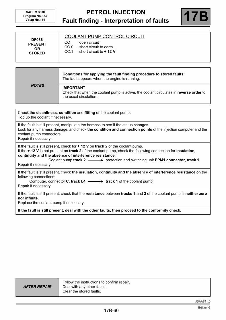
PETROL INJECTIONFault finding - Interpretation of faults 17B
17B-60
SAGEM 3000Program No.: A7
Vdiag No.: 44
DF086 PRESENT
OR STORED
COOLANT PUMP CONTROL CIRCUITCO : open circuitCO.0 : short circuit to earthCC.1 : short circuit to + 12 V
NOTES
Conditions for applying the fault finding procedure to stored faults:The fault appears when the engine is running.
IMPORTANTCheck that when the coolant pump is active, the coolant circulates in reverse order to the usual circulation.
Check the cleanliness, condition and fitting of the coolant pump.Top up the coolant if necessary.
If the fault is still present, manipulate the harness to see if the status changes.Look for any harness damage, and check the condition and connection points of the injection computer and the coolant pump connectors.Repair if necessary.
If the fault is still present, check for + 12 V on track 2 of the coolant pump.If the + 12 V is not present on track 2 of the coolant pump, check the following connection for insulation, continuity and the absence of interference resistance:
Coolant pump track 2 protection and switching unit PPM1 connector, track 1Repair if necessary.
If the fault is still present, check the insulation, continuity and the absence of interference resistance on the following connections:
Computer, connector C, track L4 track 1 of the coolant pumpRepair if necessary.
If the fault is still present, check that the resistance between tracks 1 and 2 of the coolant pump is neither zero nor infinite.Replace the coolant pump if necessary.
If the fault is still present, deal with the other faults, then proceed to the conformity check.
AFTER REPAIRFollow the instructions to confirm repair.Deal with any other faults.Clear the stored faults.
JSAA741.0
Edition 6
PETROL INJECTIONFault finding - Interpretation of faults 17B
17B-61
SAGEM 3000Program No.: A7
Vdiag No.: 44
DF088 PRESENT
OR STORED
PINKING SENSOR CIRCUIT1.DEF: pinking signal fault
NOTES
Conditions for applying the fault finding procedure to stored faults:The fault is declared present in a warm engine road test at an engine speed above 2500 rpm.
Special note:– OBD warning light comes on.
Check the cleanliness and condition of the pinking sensor and its connections.Check the tightness of the pinking sensor.
Disconnect the battery and the injection computer.Check the cleanliness and condition of the connections.Using the universal bornier, check for insulation and continuity on the following connections:
Computer, connector B, track B3 Track 2 of the pinking sensorComputer, connector B, track B4 Track 1 of the pinking sensorComputer, connector B, track B2 Shielding of the pinking sensor
Repair if necessary.
Check the conformity of the fuel in the tank.Check the conformity of the spark plugs.
If the fault is still present, deal with the other faults, then proceed to the conformity check.
AFTER REPAIRFollow the instructions to confirm repair.Deal with any other faults.Clear the stored faults.
JSAA741.0
Edition 6
PETROL INJECTIONFault finding - Interpretation of faults 17B
17B-62
SAGEM 3000Program No.: A7
Vdiag No.: 44
DF089 PRESENT
OR STORED
INLET MANIFOLD PRESSURE SENSOR CIRCUIT1.DEF: voltage outside tolerance range2.DEF: inconsistent signal
NOTES
Priority for dealing with a combination of faults:Deal with DF012 Sensor feed voltage no. 2 fault as a priority if it is present or stored.
Conditions for applying the fault finding procedure to stored faults:The fault appears after:– the ignition is switched off and dialogue is lost,– the ignition has been switched on again and dialogue re-established,– a 10 second delay at idle speed.
Special note:– OBD warning light illuminated,– throttle valve defect mode types 5 and 6.
Check the cleanliness and condition of the manifold pressure sensor and its connections.Repair if necessary.
Disconnect the battery and the injection computer.Check the cleanliness and condition of the connections.Using the universal bornier, check the insulation and continuity on the following connections:
Computer, connector B, track H2 Track 1 of the manifold pressure sensor.Computer, connector B, track H3 Track 3 of the manifold pressure sensorComputer, connector B, track H4 Track 2 of the manifold pressure sensor
Repair if necessary.
If the fault is still present, deal with the other faults, then proceed to the conformity check.
AFTER REPAIRFollow the instructions to confirm repair.Deal with any other faults.Clear the stored faults.
JSAA741.0
Edition 6
PETROL INJECTIONFault finding - Interpretation of faults 17B
17B-63
SAGEM 3000Program No.: A7
Vdiag No.: 44
DF091PRESENT
ORSTORED
VEHICLE SPEED SIGNAL1.DEF: error in speed signal from the ABS
NOTES
Conditions for applying the fault finding procedure to stored faults:The fault appears when the engine is running.
Special note:– OBD warning light comes on.
Run a multiplex network test (see 88B, Multiplex).
If the fault is still present, carry out fault finding on the ABS - ESP system (see 38C, Anti-lock braking system).
AFTER REPAIRDeal with any faults displayed by the diagnostic tool.Clear the computer memory.Carry out a road test followed by another check with the diagnostic tool.
JSAA741.0
Edition 6
PETROL INJECTIONFault finding - Interpretation of faults 17B
17B-64
SAGEM 3000Program No.: A7
Vdiag No.: 44
DF092PRESENT
ORSTORED
UPSTREAM OXYGEN SENSOR CIRCUITCO.0 : open circuit or short circuit to earthCC.1 : short circuit to + 12 V1.DEF: component in bad condition
NOTES
Priority for dealing with a combination of faults:Apply the procedure for dealing with faults DF011 Sensor supply voltage no. 1, DF046 Battery voltage, DF082 Upstream oxygen sensor heating circuit or DF084 Actuator control relay circuit first if they are present or stored.
Conditions for applying the fault finding procedure to stored faults:The fault is declared present with the engine running after 5 minutes in richness regulation.
Special note:– OBD warning light comes on.
Check the cleanliness and condition of the upstream oxygen sensor connections.Repair if necessary.
Disconnect the battery and the injection computer.Check the cleanliness and condition of the connections.Using the Universal bornier, check the insulation and continuity of the following connections:
Computer, connector C, track C1 Track D of the upstream oxygen sensorComputer, connector C, track B1 Track C of the upstream oxygen sensor
Repair if necessary.
If the fault is still present, deal with the other faults, then proceed to the conformity check.
AFTER REPAIRDeal with any faults displayed by the diagnostic tool.Clear the computer memory.Carry out a road test followed by another check with the diagnostic tool.
JSAA741.0
Edition 6
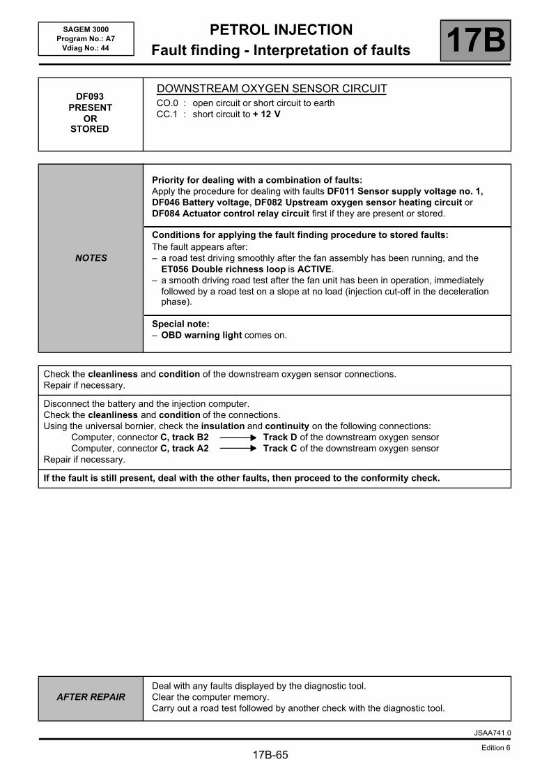
PETROL INJECTIONFault finding - Interpretation of faults 17B
17B-65
SAGEM 3000Program No.: A7
Vdiag No.: 44
DF093PRESENT
ORSTORED
DOWNSTREAM OXYGEN SENSOR CIRCUITCO.0 : open circuit or short circuit to earthCC.1 : short circuit to + 12 V
NOTES
Priority for dealing with a combination of faults:Apply the procedure for dealing with faults DF011 Sensor supply voltage no. 1, DF046 Battery voltage, DF082 Upstream oxygen sensor heating circuit or DF084 Actuator control relay circuit first if they are present or stored.
Conditions for applying the fault finding procedure to stored faults:The fault appears after:– a road test driving smoothly after the fan assembly has been running, and the
ET056 Double richness loop is ACTIVE.– a smooth driving road test after the fan unit has been in operation, immediately
followed by a road test on a slope at no load (injection cut-off in the deceleration phase).
Special note:– OBD warning light comes on.
Check the cleanliness and condition of the downstream oxygen sensor connections.Repair if necessary.
Disconnect the battery and the injection computer.Check the cleanliness and condition of the connections.Using the universal bornier, check the insulation and continuity on the following connections:
Computer, connector C, track B2 Track D of the downstream oxygen sensorComputer, connector C, track A2 Track C of the downstream oxygen sensor
Repair if necessary.
If the fault is still present, deal with the other faults, then proceed to the conformity check.
AFTER REPAIRDeal with any faults displayed by the diagnostic tool.Clear the computer memory.Carry out a road test followed by another check with the diagnostic tool.
JSAA741.0
Edition 6
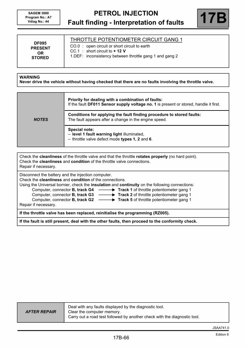
PETROL INJECTIONFault finding - Interpretation of faults 17B
17B-66
SAGEM 3000Program No.: A7
Vdiag No.: 44
DF095PRESENT
ORSTORED
THROTTLE POTENTIOMETER CIRCUIT GANG 1CO.0 : open circuit or short circuit to earthCC.1 : short circuit to + 12 V1.DEF: inconsistency between throttle gang 1 and gang 2
WARNINGNever drive the vehicle without having checked that there are no faults involving the throttle valve.
NOTES
Priority for dealing with a combination of faults:If the fault DF011 Sensor supply voltage no. 1 is present or stored, handle it first.
Conditions for applying the fault finding procedure to stored faults:The fault appears after a change in the engine speed.
Special note:– level 1 fault warning light illuminated,– throttle valve defect mode types 1, 2 and 6.
Check the cleanliness of the throttle valve and that the throttle rotates properly (no hard point).Check the cleanliness and condition of the throttle valve connections.Repair if necessary.
Disconnect the battery and the injection computer.Check the cleanliness and condition of the connections.Using the Universal bornier, check the insulation and continuity on the following connections:
Computer, connector B, track G4 Track 1 of throttle potentiometer gang 1Computer, connector B, track G3 Track 2 of throttle potentiometer gang 1Computer, connector B, track G2 Track 5 of throttle potentiometer gang 1
Repair if necessary.
If the throttle valve has been replaced, reinitialise the programming (RZ005).
If the fault is still present, deal with the other faults, then proceed to the conformity check.
AFTER REPAIRDeal with any faults displayed by the diagnostic tool.Clear the computer memory.Carry out a road test followed by another check with the diagnostic tool.
JSAA741.0
Edition 6
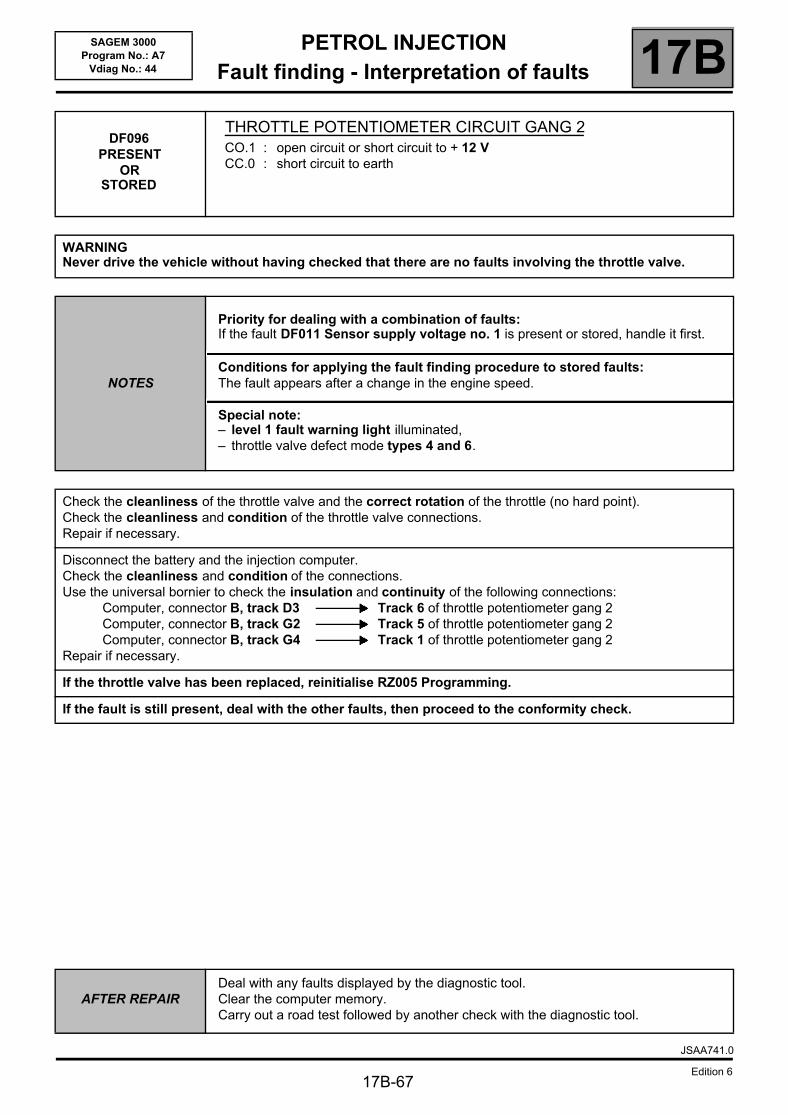
PETROL INJECTIONFault finding - Interpretation of faults 17B
17B-67
SAGEM 3000Program No.: A7
Vdiag No.: 44
DF096 PRESENT
OR STORED
THROTTLE POTENTIOMETER CIRCUIT GANG 2CO.1 : open circuit or short circuit to + 12 VCC.0 : short circuit to earth
WARNINGNever drive the vehicle without having checked that there are no faults involving the throttle valve.
NOTES
Priority for dealing with a combination of faults:If the fault DF011 Sensor supply voltage no. 1 is present or stored, handle it first.
Conditions for applying the fault finding procedure to stored faults:The fault appears after a change in the engine speed.
Special note:– level 1 fault warning light illuminated,– throttle valve defect mode types 4 and 6.
Check the cleanliness of the throttle valve and the correct rotation of the throttle (no hard point).Check the cleanliness and condition of the throttle valve connections.Repair if necessary.
Disconnect the battery and the injection computer.Check the cleanliness and condition of the connections.Use the universal bornier to check the insulation and continuity of the following connections:
Computer, connector B, track D3 Track 6 of throttle potentiometer gang 2Computer, connector B, track G2 Track 5 of throttle potentiometer gang 2Computer, connector B, track G4 Track 1 of throttle potentiometer gang 2
Repair if necessary.
If the throttle valve has been replaced, reinitialise RZ005 Programming.
If the fault is still present, deal with the other faults, then proceed to the conformity check.
AFTER REPAIRDeal with any faults displayed by the diagnostic tool.Clear the computer memory.Carry out a road test followed by another check with the diagnostic tool.
JSAA741.0
Edition 6
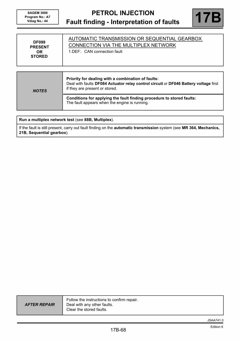
PETROL INJECTIONFault finding - Interpretation of faults 17B
17B-68
SAGEM 3000Program No.: A7
Vdiag No.: 44
DF099PRESENT
ORSTORED
AUTOMATIC TRANSMISSION OR SEQUENTIAL GEARBOX CONNECTION VIA THE MULTIPLEX NETWORK1.DEF: CAN connection fault
NOTES
Priority for dealing with a combination of faults:Deal with faults DF084 Actuator relay control circuit or DF046 Battery voltage first if they are present or stored.
Conditions for applying the fault finding procedure to stored faults:The fault appears when the engine is running.
Run a multiplex network test (see 88B, Multiplex).
If the fault is still present, carry out fault finding on the automatic transmission system (see MR 364, Mechanics, 21B, Sequential gearbox).
AFTER REPAIRFollow the instructions to confirm repair.Deal with any other faults.Clear the stored faults.
JSAA741.0
Edition 6

PETROL INJECTIONFault finding - Interpretation of faults 17B
17B-69
SAGEM 3000Program No.: A7
Vdiag No.: 44
DF100PRESENT
ORSTORED
INSTRUMENT PANEL MULTIPLEX CONNECTION1.DEF: CAN connection fault
NOTESConditions for applying the fault finding procedure to stored faults:The fault is declared present after an attempt is made to start the engine.
Run a multiplex network test (see 88B, Multiplex).
If the fault is still present, carry out fault finding on the Instrument panel system (see 83A, Instrument panel).
AFTER REPAIRDeal with any faults displayed by the diagnostic tool.Clear the computer memory.Carry out a road test followed by another check with the diagnostic tool.
JSAA741.0
Edition 6
PETROL INJECTIONFault finding - Interpretation of faults 17B
17B-70
SAGEM 3000Program No.: A7
Vdiag No.: 44
DF101PRESENT
ORSTORED
ELECTRONIC STABILITY PROGRAM MULTIPLEX CONNECTION1.DEF: CAN connection fault
NOTESConditions for applying the fault finding procedure to stored faults:The fault is declared present after an attempt is made to start the engine.
Run a multiplex network test (see 88B, Multiplex).
If the fault is still present, carry out fault finding on the ABS - ESP system (see 38C, Anti-lock braking system).
AFTER REPAIRDeal with any faults displayed by the diagnostic tool.Clear the computer memory.Carry out a road test followed by another check with the diagnostic tool.
JSAA741.0
Edition 6
PETROL INJECTIONFault finding - Interpretation of faults 17B
17B-71
SAGEM 3000Program No.: A7
Vdiag No.: 44
DF105 PRESENT
OR STORED
CRUISE CONTROL/SPEED LIMITER ON/OFF CIRCUIT1.DEF: cruise control/speed limiter on/off button inconsistency
NOTESConditions for applying the fault finding procedure to stored faults:The fault is declared present after a road test using the cruise control then the speed limiter function.
Check the cleanliness and condition of the cruise control/speed limiter on/off switch and its connections.Repair if necessary
Check for the + 12 V feed on track A2 of the cruise control or speed limiter selector switch connector with the ignition on.Repair if necessary.
Disconnect the battery.Disconnect the computer. Check the cleanliness and condition of the connections.Using the universal bornier, check the insulation and continuity on the following connections:
Computer, connector A, track A2 Track A3 of the cruise control or speed limiter on/off switchComputer, connector A, track C3 Track B1 of the cruise control or speed limiter on/off switch
Repair if necessary.
If the fault is still present, deal with the other faults, then proceed to the conformity check.
AFTER REPAIRDeal with any faults displayed by the diagnostic tool.Clear the computer memory.Carry out a road test followed by another check with the diagnostic tool.
JSAA741.0
Edition 6
PETROL INJECTIONFault finding - Interpretation of faults 17B
17B-72
SAGEM 3000Program No.: A7
Vdiag No.: 44
DF106PRESENT
ORSTORED
CRUISE CONTROL/SPEED LIMITER SELECTOR SWITCH ON STEERING WHEEL1.DEF: inconsistent data
IMPORTANTTo remove or check the Cruise control/speed limiter control switches, the airbag must be removed (see MR 364, Mechanical, 88C, Airbag and pretensioners).
NOTESConditions for applying the fault finding procedure to stored faults:The fault is declared present after a road test using the cruise control then the speed limiter function.
Check the cleanliness and condition of the incrementing switches on the steering wheel and their connections.Repair if necessary.
Check that the earth is present on track 2 of the incrementing switches on the steering wheel.Repair if necessary.
Disconnect the battery.Disconnect the computer. Check the cleanliness and condition of the connections.Using the Universal bornier, check the insulation and continuity of the following connections:
Computer, connector A, track D2 Track 2 of the steering wheel control switchComputer, connector A, track D3 Track 1 of the steering wheel control switch
Repair if necessary.
If the fault is still present, deal with the other faults, then proceed to the conformity check.
AFTER REPAIRDeal with any faults displayed by the diagnostic tool.Clear the computer memory.Carry out a road test followed by another check with the diagnostic tool.
JSAA741.0
Edition 6
PETROL INJECTIONFault finding - Interpretation of faults 17B
17B-73
SAGEM 3000Program No.: A7
Vdiag No.: 44
DF109 PRESENT
OR STORED
LOW FUEL LEVEL MISFIRING1.DEF: destructive misfiring2.DEF: pollutant misfiring
NOTES
Priority for dealing with a combination of faults:– fuel supply system: DF085, DF026, DF027, DF028 and DF029.– combustion misfires: DF059, DF060, DF061, DF062, DF065 in 1.DEF or 2.DEF.
Conditions for applying the fault finding procedure to stored faults:The fault is declared present after starting the engine and under the following conditions:– there must be no further electrical faults,– programming must be carried out,– engine hot (minimum 75 °°°°C),– idling with all the electrical consumers activated for 15 minutes.
Special note:– OBD warning light comes on.
Check that there is fuel in the tank.Check that the correct fuel is being used.
If there is no present or stored misfiring fault, the misfiring was caused by the low fuel level.Clear fault DF109.
AFTER REPAIR
Ensure that all the faults have been dealt with.Do not clear the programming.Checking that the system has been properly repaired:– there must be no further electrical faults,– programming has been carried out,– engine hot (minimum 75 °°°°C),– running at idle speed with all electrical consumers drawing power for 15 minutes.If the fault reappears, continue the fault finding procedure.
JSAA741.0
Edition 6
PETROL INJECTIONFault finding - Interpretation of faults 17B
17B-74
SAGEM 3000Program No.: A7
Vdiag No.: 44
DF110 PRESENT
OR STORED
CATALYTIC CONVERTER1.DEF: EOBD HC pollutant emissions threshold has been exceeded
NOTES
Priority for dealing with a combination of faults:Deal with the other faults first.There must be no other injection system faults, either present or stored.– combustion misfires: DF059, DF060, DF061, DF062, DF065 in 1.DEF or 2.DEF.
Conditions for applying the fault finding procedure to stored faults:The fault appears under the following conditions:– there must be no further electrical faults,– programming must be carried out,– engine hot (minimum 75 °°°°C),– idling with all the electrical consumers activated for 15 minutes.
Special note:– OBD warning light comes on.
Replace the catalytic converter after dealing with the causes of the misfire.
If there is no present or stored misfiring fault, the misfiring was caused by the low fuel level.Clear fault DF109.
AFTER REPAIRDeal with any faults displayed by the diagnostic tool.Clear the computer memory.Carry out a road test followed by another check with the diagnostic tool.
JSAA741.0
Edition 6
PETROL INJECTIONFault finding - Interpretation of faults 17B
17B-75
SAGEM 3000Program No.: A7
Vdiag No.: 44
DF119 PRESENT
OR STORED
CAMSHAFT SENSOR SIGNAL1.DEF: camshaft tooth event2.DEF: dephasing measurement out of range
NOTES
If faults DF084 or DF046 are present or stored, deal with them first.If faults DF154 Engine speed sensor circuit, DF080 Camshaft dephaser circuit and DF119 are all present, ignore DF080 and deal with the other 2 faults first.
Conditions for applying the fault finding procedure to stored faults:The fault is declared present after a road test.
Check the cleanliness and the condition of the camshaft sensor connectors.
Check the cleanliness and the condition of the camshaft sensor.
With the ignition on, check for + 12 V on the camshaft sensor connector (see the connector track number on the relevant wiring diagram).If + 12 V is not present: – disconnect the battery,– disconnect the connector marked PPM1 in the Protection and Switching Unit,– check the cleanliness and condition of the connections,– Use the Universal bornier to check the continuity of the following connection:
Protection and Switching Unit track 2 connector PPM1 Camshaft sensor
Reconnect the Protection and Switching Unit connector and reconnect the battery.With the ignition on, if there is still no + 12 V at the camshaft sensor connector, there is a fault in the Protection and Switching Unit.Contact Techline.
Disconnect the battery.Disconnect the computer. Check the cleanliness and condition of the connections.Use the universal bornier to check the insulation and continuity of the following connections:
Computer track E2, connector C Camshaft sensorComputer track F1, connector C Camshaft sensor
(see connector track numbers in the corresponding wiring diagram).
If the fault is still present, there is definitely a fault with the camshaft sensor target.Refer to the relevant section in the Workshop Repair Manual.
AFTER REPAIR
Apply the Stored fault diagnostic application conditions:– Continue to deal with the fault if it is present.– Ignore the fault if it is stored.Deal with any other faults.Clear the stored faults.
JSAA741.0
Edition 6
PETROL INJECTIONFault finding - Interpretation of faults 17B
17B-76
SAGEM 3000Program No.: A7
Vdiag No.: 44
DF125 PRESENT
OR STORED
TORQUE METER PROGRAMMING1.DEF: programming not carried out
NOTES
Signal:The torque meter analyses the crankshaft speed.
Conditions for applying the fault finding procedure to stored faults:The fault is declared present after the starter motor has been running for 10 seconds or at an engine speed above 600 rpm.
Special note:– OBD warning light comes on.
Reinitialising the programming:Run command RZ005.
Torque meter programming:Accelerate up to 4000 rpm in third gear then decelerate at no load to power take-up speed*.Then repeat immediately.In rare cases, fault DF125 may appear.
(*This is the moment when, during deceleration with no load, the engine drops to idle speed and recovers torque)
AFTER REPAIRDeal with any faults displayed by the diagnostic tool.Clear the computer memory.Carry out a road test followed by another check with the diagnostic tool.
JSAA741.0
Edition 6
PETROL INJECTIONFault finding - Interpretation of faults 17B
17B-77
SAGEM 3000Program No.: A7
Vdiag No.: 44
DF126 PRESENT
OR STORED
PASSENGER COMPARTMENT HEATING RESISTOR1.DEF: no signal or inconsistent signal from the UCH
NOTESConditions for applying the fault finding procedure to stored faults:The fault is declared present after an attempt is made to start the engine.
Run a multiplex network test (see 88B, Multiplex).
If the fault is still present, run fault finding on the UCH system (see 87A, UCH).
AFTER REPAIRDeal with any faults displayed by the diagnostic tool.Clear the computer memory.Carry out a road test followed by another check with the diagnostic tool.
JSAA741.0
Edition 6
PETROL INJECTIONFault finding - Interpretation of faults 17B
17B-78
SAGEM 3000Program No.: A7
Vdiag No.: 44
DF127PRESENT
ORSTORED
BRAKE SWITCH 1 CIRCUIT1.DEF: fault on one of the two brake pedal contacts
NOTES
Conditions for applying the fault finding procedure to stored faults:The fault is declared present:– with the engine running,– with the brake pedal depressed,– with cruise control ON.
Check that the pedal assembly is in good condition.Check the cleanliness and condition of the dual-contact brake switch and its connections.Repair if necessary.
Disconnect the battery.Disconnect the computer. Check the cleanliness and condition of the connections.Using the Universal bornier, check the insulation and continuity of the following connection:
Computer, connector A, track E4 Track 3 of the brake pedalRepair if necessary.
If the fault is still present, replace the switch.
AFTER REPAIRDeal with any faults displayed by the diagnostic tool.Clear the computer memory.Carry out a road test followed by another check with the diagnostic tool.
JSAA741.0
Edition 6
PETROL INJECTIONFault finding - Interpretation of faults 17B
17B-79
SAGEM 3000Program No.: A7
Vdiag No.: 44
DF128PRESENT
ORSTORED
BRAKE SWITCH 2 CIRCUIT1.DEF: fault on both brake pedal contacts
NOTES
Priority for dealing with a combination of faults:Apply the procedure for dealing with fault DF127 Gang 1 switch circuit first if it is present or stored.
Conditions for applying the fault finding procedure to stored faults:The fault is declared present:– with the engine running,– with the brake pedal depressed,– with the cruise control ON with a cruising speed set.
Run a multiplex network test (see 88B, Multiplex).
If the fault is still present, run fault finding on the UCH system (see 87A, UCH).
AFTER REPAIRDeal with any faults displayed by the diagnostic tool.Clear the computer memory.Carry out a road test followed by another check with the diagnostic tool.
JSAA741.0
Edition 6
PETROL INJECTIONFault finding - Interpretation of faults 17B
17B-80
SAGEM 3000Program No.: A7
Vdiag No.: 44
DF154PRESENT
OR STORED
FLYWHEEL SIGNAL SENSOR CIRCUIT1.DEF: flywheel target fault2.DEF: no speed signal or interference signal
NOTES
Priority for dealing with a combination of faults:If faults DF154, DF119 Camshaft sensor signal and DF080 Camshaft dephaser circuit are present, disregard DF080 and deal first with the other two faults.
Conditions for applying the fault finding procedure to stored faults:The fault is declared present after the starter motor has been running for 10 seconds or at an engine speed above 600 rpm.
Special note:– OBD warning light comes on.
1.DEF NOTES None.
Check the cleanliness, condition and the assembly of the flywheel.Repair if necessary.
If the flywheel has been replaced or removed, the flywheel target has to be reinitialised, then reprogrammed.
Programming reinitialisation:Run command RZ005.
Carrying out the flywheel target programming:Accelerate up to 4000 rpm in third gear then decelerate at no load to power take-up speed*.Then repeat immediately.In rare cases, fault DF125 Torquemeter programming may appear.
(*This is the moment when, during deceleration with no load, the engine drops to idling speed and recovers torque).
JSAA741.0
Edition 6
PETROL INJECTIONFault finding - Interpretation of faults 17B
17B-81
SAGEM 3000Program No.: A7
Vdiag No.: 44
DF398PRESENT
OR STORED
FUEL CIRCUIT OPERATING FAULT1.DEF: petrol circuit fault
NOTES
Priority for dealing with a combination of faults:Apply the procedure for dealing with faults DF081 Solenoid valve canister bleed and DF085 Fuel pump relay first if they are present or stored.
Conditions for applying the fault finding procedure to stored faults:The fault is declared present after an attempt is made to start the engine.
Special note:– OBD warning light comes on.
Check the cleanliness, condition and fitting of the fuel vapour absorber.Repair if necessary.
If the fault is still present, manipulate the harness so that the status changes (present ⇒ stored).Look for any damage to the wiring harness, and check the condition and connection of the injection computer and fuel vapour absorber connectors.Repair if necessary.
If the fault is still present, check for the + 12 V on track 1 of the fuel vapour absorber.If there is no + 12 V feed, check the insulation, continuity and the absence of interference resistance on the following connection:
Fuel vapour absorber track 1 track 2 of connector PPM1 on the Protection and Switching UnitRepair if necessary.
If the fault is still present, disconnect the battery and the injection computer.Check the insulation, continuity and the absence of interference resistance on the following connection:
Computer, connector C, track E1 track 2 of the fuel vapour absorberRepair if necessary.
If the fault is still present, measure the resistance between tracks 1 and 2 of the fuel vapour absorber bleed solenoid valve.Replace the bleed solenoid valve for the fuel vapour absorber if the resistance is not 26 ΩΩΩΩ ±±±± 4 ΩΩΩΩ at 23 °°°°C.
If the fault is still present, check the insulation, continuity and the absence of interference resistance on the following connection:
Computer, connector C, track D1 track 1 of connector PEM of the Protection and Switching UnitRepair if necessary.
If the fault is still present, deal with the other faults, then proceed to the conformity check.
AFTER REPAIRFollow the instructions to confirm repair.Deal with any other faults.Clear the stored faults.
JSAA741.0
Edition 6
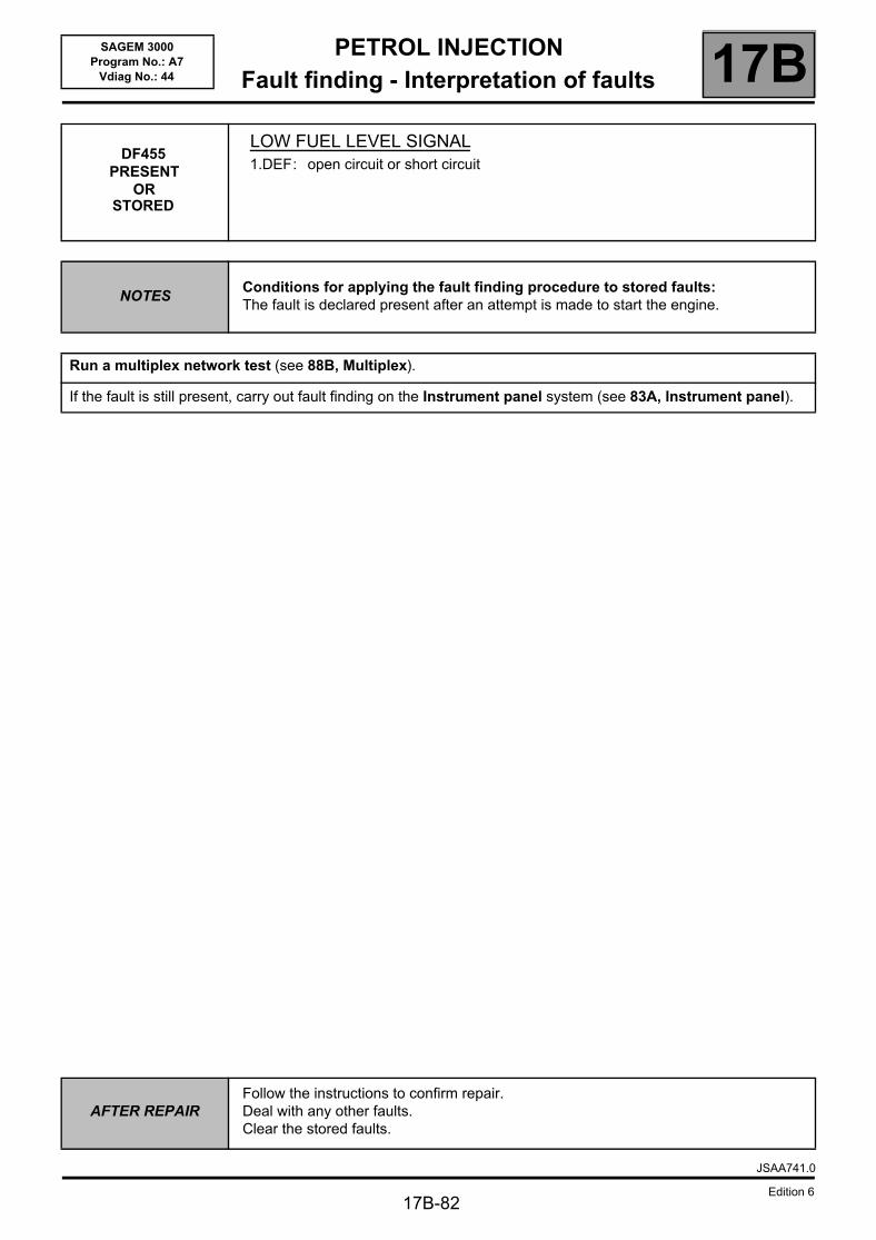
PETROL INJECTIONFault finding - Interpretation of faults 17B
17B-82
SAGEM 3000Program No.: A7
Vdiag No.: 44
DF455PRESENT
OR STORED
LOW FUEL LEVEL SIGNAL1.DEF: open circuit or short circuit
NOTESConditions for applying the fault finding procedure to stored faults:The fault is declared present after an attempt is made to start the engine.
Run a multiplex network test (see 88B, Multiplex).
If the fault is still present, carry out fault finding on the Instrument panel system (see 83A, Instrument panel).
AFTER REPAIRFollow the instructions to confirm repair.Deal with any other faults.Clear the stored faults.
JSAA741.0
Edition 6
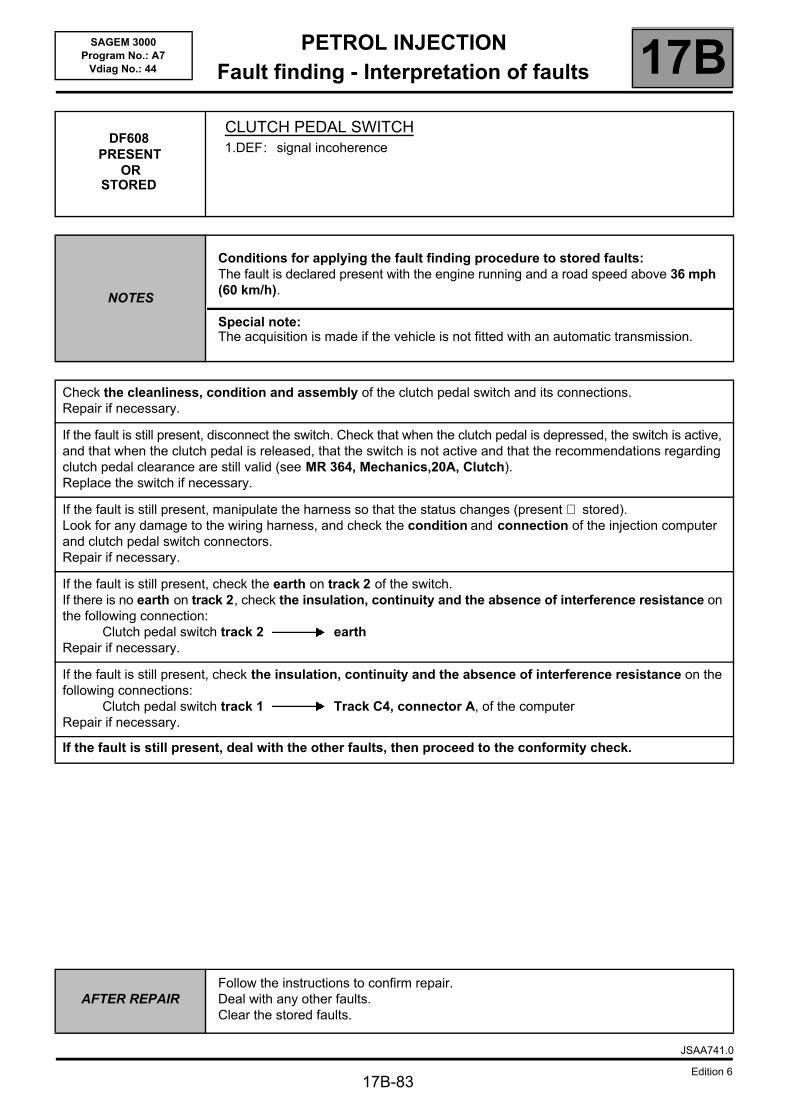
PETROL INJECTIONFault finding - Interpretation of faults 17B
17B-83
SAGEM 3000Program No.: A7
Vdiag No.: 44
DF608 PRESENT
ORSTORED
CLUTCH PEDAL SWITCH1.DEF: signal incoherence
NOTES
Conditions for applying the fault finding procedure to stored faults:The fault is declared present with the engine running and a road speed above 36 mph (60 km/h).
Special note:The acquisition is made if the vehicle is not fitted with an automatic transmission.
Check the cleanliness, condition and assembly of the clutch pedal switch and its connections.Repair if necessary.
If the fault is still present, disconnect the switch. Check that when the clutch pedal is depressed, the switch is active, and that when the clutch pedal is released, that the switch is not active and that the recommendations regarding clutch pedal clearance are still valid (see MR 364, Mechanics,20A, Clutch).Replace the switch if necessary.
If the fault is still present, manipulate the harness so that the status changes (present ⇒ stored).Look for any damage to the wiring harness, and check the condition and connection of the injection computer and clutch pedal switch connectors.Repair if necessary.
If the fault is still present, check the earth on track 2 of the switch.If there is no earth on track 2, check the insulation, continuity and the absence of interference resistance on the following connection:
Clutch pedal switch track 2 earthRepair if necessary.
If the fault is still present, check the insulation, continuity and the absence of interference resistance on the following connections:
Clutch pedal switch track 1 Track C4, connector A, of the computerRepair if necessary.
If the fault is still present, deal with the other faults, then proceed to the conformity check.
AFTER REPAIRFollow the instructions to confirm repair.Deal with any other faults.Clear the stored faults.
JSAA741.0
Edition 6
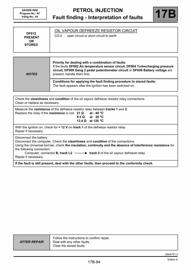
PETROL INJECTIONFault finding - Interpretation of faults 17B
17B-84
SAGEM 3000Program No.: A7
Vdiag No.: 44
DF612 PRESENT
OR STORED
OIL VAPOUR DEFREEZE RESISTOR CIRCUITCO.0 : open circuit or short circuit to earth
NOTES
Priority for dealing with a combination of faults:If the faults DF002 Air temperature sensor circuit, DF004 Turbocharging pressure circuit, DF009 Gang 2 pedal potentiometer circuit or DF046 Battery voltage are present, handle them first.
Conditions for applying the fault finding procedure to stored faults:The fault appears after the ignition has been switched on.
Check the cleanliness and condition of the oil vapour defreeze resistor relay connections.Clean or replace as necessary.
Measure the resistance of the defreeze resistor relay between tracks 1 and 2.Replace the relay if the resistance is not: 21 ΩΩΩΩ at - 40 °°°°C
9.5 ΩΩΩΩ at 20 °°°°C13.4 ΩΩΩΩ at 120 °°°°C
With the ignition on, check for + 12 V on track 1 of the defreeze resistor relay.Repair if necessary.
Disconnect the battery.Disconnect the computer. Check the cleanliness and condition of the connections.Using the Universal bornier, check the insulation, continuity and the absence of interference resistance for the following connection:
Computer, connector B, track L2 track 2 of the oil vapour defreeze relayRepair if necessary.
If the fault is still present, deal with the other faults, then proceed to the conformity check.
AFTER REPAIRFollow the instructions to confirm repair.Deal with any other faults.Clear the stored faults.
JSAA741.0
Edition 6
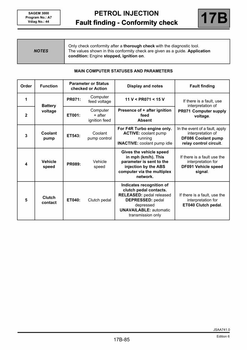
PETROL INJECTIONFault finding - Conformity check 17B
17B-85
SAGEM 3000Program No.: A7
Vdiag No.: 44 Fault finding - Conformity check
MAIN COMPUTER STATUSES AND PARAMETERS
NOTESOnly check conformity after a thorough check with the diagnostic tool.The values shown in this conformity check are given as a guide. Application condition: Engine stopped, ignition on.
Order FunctionParameter or Status checked or Action
Display and notes Fault finding
1
Battery voltage
PR071:Computer
feed voltage 11 V < PR071 < 15 V If there is a fault, use interpretation of
PR071 Computer supply voltage.2 ET001:
Computer + after
ignition feed
Presence of + after ignition feed
Absent
3Coolant pump
ET543: Coolant
pump control
For F4R Turbo engine only.ACTIVE: coolant pump
runningINACTIVE: coolant pump idle
In the event of a fault, apply interpretation of
DF086 Coolant pump relay control circuit.
4Vehicle speed
PR089:Vehicle speed
Gives the vehicle speed in mph (km/h). This
parameter is sent to the injection by the ABS
computer via the multiplex network.
If there is a fault use the interpretation for
DF091 Vehicle speed signal.
5Clutch contact
ET040: Clutch pedal
Indicates recognition of clutch pedal contacts.
RELEASED: pedal releasedDEPRESSED: pedal
depressedUNAVAILABLE: automatic
transmission only
If there is a fault, use the interpretation for
ET040 Clutch pedal.
JSAA741.0
Edition 6
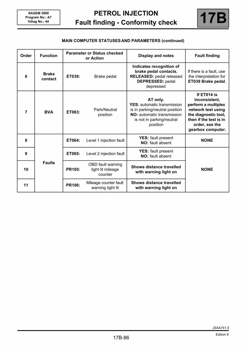
PETROL INJECTIONFault finding - Conformity check 17B
17B-86
SAGEM 3000Program No.: A7
Vdiag No.: 44
MAIN COMPUTER STATUSES AND PARAMETERS (continued)
Order FunctionParameter or Status checked
or ActionDisplay and notes Fault finding
6Brake
contactET039: Brake pedal
Indicates recognition of brake pedal contacts.
RELEASED: pedal releasedDEPRESSED: pedal
depressed
If there is a fault, use the interpretation for ET039 Brake pedal.
7 BVA ET063: Park/Neutral
position
AT only.YES: automatic transmission is in parking/neutral positionNO: automatic transmission
is not in parking/neutral position
If ET014 is inconsistent,
perform a multiplex network test using the diagnostic tool, then if the test is in
order, see the gearbox computer.
8
Faults
ET064: Level 1 injection faultYES: fault presentNO: fault absent
NONE
9 ET065: Level 2 injection faultYES: fault presentNO: fault absent
NONE10 PR105:OBD fault warning
light lit mileage counter
Shows distance travelled with warning light on
11 PR106:Mileage counter fault
warning light litShows distance travelled
with warning light on
JSAA741.0
Edition 6
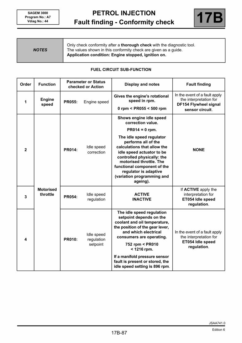
PETROL INJECTIONFault finding - Conformity check 17B
17B-87
SAGEM 3000Program No.: A7
Vdiag No.: 44
FUEL CIRCUIT SUB-FUNCTION
NOTESOnly check conformity after a thorough check with the diagnostic tool.The values shown in this conformity check are given as a guide.Application condition: Engine stopped, ignition on.
Order FunctionParameter or Status checked or Action
Display and notes Fault finding
1Engine speed
PR055: Engine speedGives the engine's rotational
speed in rpm.
0 rpm < PR055 < 500 rpm
In the event of a fault apply the interpretation for
DF154 Flywheel signal sensor circuit.
2
Motorised throttle
PR014:Idle speed correction
Shows engine idle speed correction value.
PR014 = 0 rpm.
The idle speed regulator performs all of the
calculations that allow the idle speed actuator to be controlled physically: the
motorised throttle. The functional component of the
regulator is adaptive (variation programming and
ageing).
NONE
3 PR054: Idle speed regulation
ACTIVEINACTIVE
If ACTIVE apply the interpretation for
ET054 Idle speed regulation.
4 PR010:Idle speed regulation setpoint
The idle speed regulation setpoint depends on the
coolant and oil temperature, the position of the gear lever,
and which electrical consumers are operating.
752 rpm < PR010 < 1216 rpm.
If a manifold pressure sensor fault is present or stored, the idle speed setting is 896 rpm.
In the event of a fault apply the interpretation for ET054 Idle speed
regulation.
JSAA741.0
Edition 6
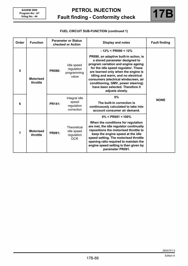
PETROL INJECTIONFault finding - Conformity check 17B
17B-88
SAGEM 3000Program No.: A7
Vdiag No.: 44
FUEL CIRCUIT SUB-FUNCTION (continued 1)
Order FunctionParameter or Status checked or Action
Display and notes Fault finding
5
Motorised throttle
PR090:
Idle speed regulation
programming value
- 12% < PR090 < 12%
PR090, an adaptive built-in action, is a stored parameter designed to
program variation and engine ageing for the idle speed regulator. These
are learned only when the engine is idling and warm, and no electrical
consumers (electrical windscreen, air conditioning, GMV, power steering)
have been selected. Therefore it adjusts slowly.
NONE6 PR141:
Integral idle speed
regulation correction
0%
The built-in correction is continuously calculated to take into
account consumer air demand.
7Motorised
throttle PR091:
Theoretical idle speed regulation
OCR
0% < PR091 < 100%
When the conditions for regulation are met, the idle regulator continually repositions the motorised throttle to
keep the engine speed at the idle speed setting. The motorised throttle opening ratio required to maintain the engine speed setting is then given by
parameter PR091.
JSAA741.0
Edition 6
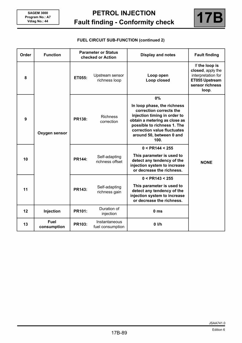
PETROL INJECTIONFault finding - Conformity check 17B
17B-89
SAGEM 3000Program No.: A7
Vdiag No.: 44
FUEL CIRCUIT SUB-FUNCTION (continued 2)
Order FunctionParameter or Status checked or Action
Display and notes Fault finding
8
Oxygen sensor
ET055: Upstream sensor
richness loopLoop open
Loop closed
If the loop is closed, apply the interpretation for ET055 Upstream sensor richness
loop.
9 PR138:Richness correction
0%
In loop phase, the richness correction corrects the
injection timing in order to obtain a metering as close as possible to richness 1. The correction value fluctuates around 50, between 0 and
100.
NONE10 PR144:
Self-adapting richness offset
0 < PR144 < 255
This parameter is used to detect any tendency of the
injection system to increase or decrease the richness.
11 PR143: Self-adapting richness gain
0 < PR143 < 255
This parameter is used to detect any tendency of the
injection system to increase or decrease the richness.
12 Injection PR101:Duration of
injection0 ms
13Fuel
consumptionPR103:
Instantaneous fuel consumption
0 l/h
JSAA741.0
Edition 6
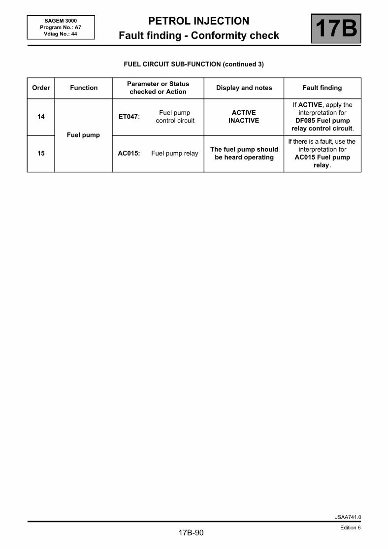
PETROL INJECTIONFault finding - Conformity check 17B
17B-90
SAGEM 3000Program No.: A7
Vdiag No.: 44
FUEL CIRCUIT SUB-FUNCTION (continued 3)
Order FunctionParameter or Status checked or Action
Display and notes Fault finding
14
Fuel pump
ET047: Fuel pump
control circuitACTIVE
INACTIVE
If ACTIVE, apply the interpretation for
DF085 Fuel pump relay control circuit.
15 AC015: Fuel pump relayThe fuel pump should
be heard operating
If there is a fault, use the interpretation for
AC015 Fuel pump relay.
JSAA741.0
Edition 6
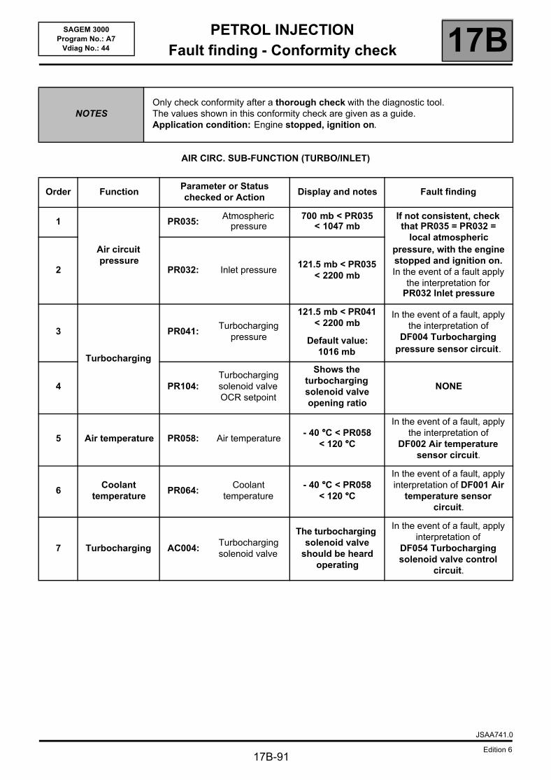
PETROL INJECTIONFault finding - Conformity check 17B
17B-91
SAGEM 3000Program No.: A7
Vdiag No.: 44
AIR CIRC. SUB-FUNCTION (TURBO/INLET)
NOTESOnly check conformity after a thorough check with the diagnostic tool.The values shown in this conformity check are given as a guide.Application condition: Engine stopped, ignition on.
Order FunctionParameter or Status checked or Action
Display and notes Fault finding
1
Air circuit pressure
PR035:Atmospheric
pressure700 mb < PR035
< 1047 mbIf not consistent, check that PR035 = PR032 =
local atmospheric pressure, with the engine stopped and ignition on.In the event of a fault apply
the interpretation for PR032 Inlet pressure
2 PR032: Inlet pressure121.5 mb < PR035
< 2200 mb
3
Turbocharging
PR041:Turbocharging
pressure
121.5 mb < PR041 < 2200 mb
Default value: 1016 mb
In the event of a fault, apply the interpretation of
DF004 Turbocharging pressure sensor circuit.
4 PR104:Turbocharging solenoid valve OCR setpoint
Shows the turbocharging solenoid valve opening ratio
NONE
5 Air temperature PR058: Air temperature- 40 °°°°C < PR058
< 120 °°°°C
In the event of a fault, apply the interpretation of
DF002 Air temperature sensor circuit.
6Coolant
temperaturePR064:
Coolant temperature
- 40 °°°°C < PR058 < 120 °°°°C
In the event of a fault, apply interpretation of DF001 Air
temperature sensor circuit.
7 Turbocharging AC004:Turbocharging solenoid valve
The turbocharging solenoid valve
should be heard operating
In the event of a fault, apply interpretation of
DF054 Turbocharging solenoid valve control
circuit.
JSAA741.0
Edition 6
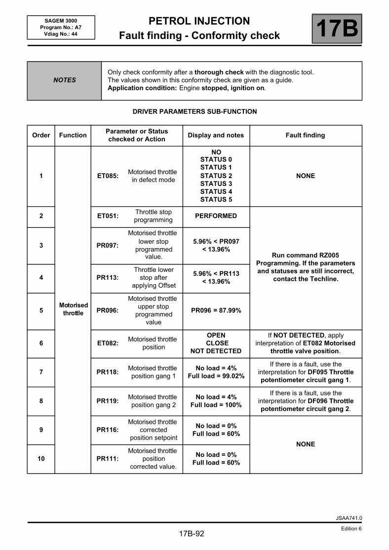
PETROL INJECTIONFault finding - Conformity check 17B
17B-92
SAGEM 3000Program No.: A7
Vdiag No.: 44
DRIVER PARAMETERS SUB-FUNCTION
NOTESOnly check conformity after a thorough check with the diagnostic tool.The values shown in this conformity check are given as a guide.Application condition: Engine stopped, ignition on.
Order FunctionParameter or Status checked or Action
Display and notes Fault finding
1
Motorisedthrottle
ET085: Motorised throttle
in defect mode
NOSTATUS 0STATUS 1STATUS 2STATUS 3STATUS 4STATUS 5
NONE
2 ET051: Throttle stop programming
PERFORMED
Run command RZ005 Programming. If the parameters and statuses are still incorrect,
contact the Techline.
3 PR097:
Motorised throttle lower stop
programmed value.
5.96% < PR097 < 13.96%
4 PR113:Throttle lower
stop after applying Offset
5.96% < PR113 < 13.96%
5 PR096:
Motorised throttle upper stop
programmed value
PR096 = 87.99%
6 ET082: Motorised throttle
position
OPEN CLOSE
NOT DETECTED
If NOT DETECTED, apply interpretation of ET082 Motorised
throttle valve position.
7 PR118:Motorised throttle position gang 1
No load = 4%Full load = 99.02%
If there is a fault, use the interpretation for DF095 Throttle potentiometer circuit gang 1.
8 PR119:Motorised throttle position gang 2
No load = 4%Full load = 100%
If there is a fault, use the interpretation for DF096 Throttle potentiometer circuit gang 2.
9 PR116:Motorised throttle
corrected position setpoint
No load = 0%Full load = 60%
NONE
10 PR111:Motorised throttle
position corrected value.
No load = 0%Full load = 60%
JSAA741.0
Edition 6
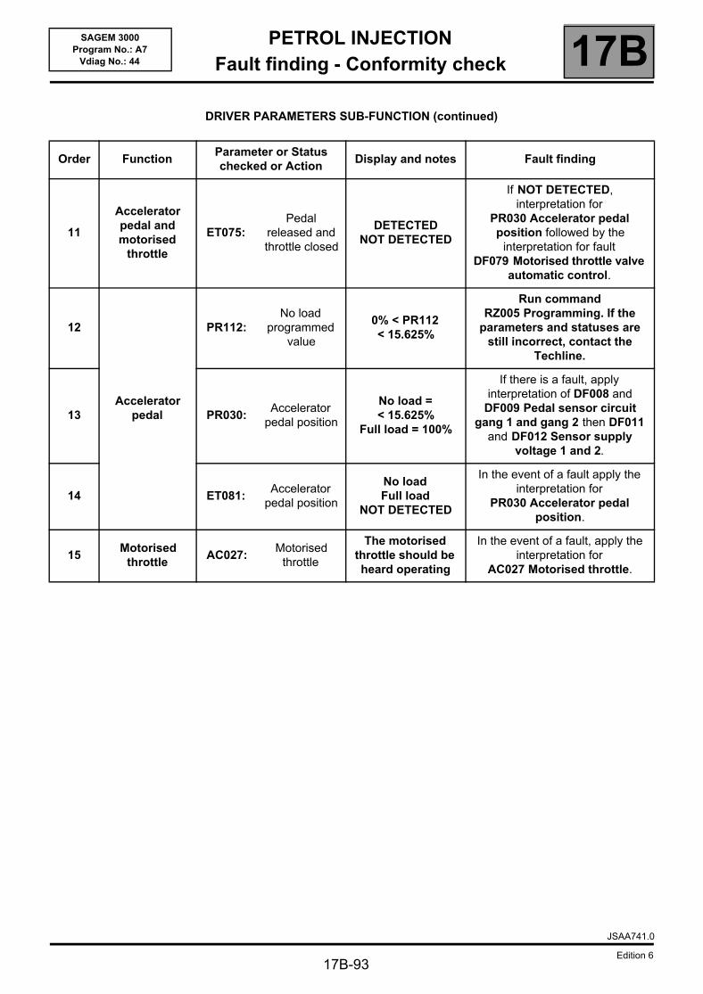
PETROL INJECTIONFault finding - Conformity check 17B
17B-93
SAGEM 3000Program No.: A7
Vdiag No.: 44
DRIVER PARAMETERS SUB-FUNCTION (continued)
Order FunctionParameter or Status checked or Action
Display and notes Fault finding
11
Accelerator pedal and motorised
throttle
ET075: Pedal
released and throttle closed
DETECTEDNOT DETECTED
If NOT DETECTED, interpretation for
PR030 Accelerator pedal position followed by the
interpretation for fault DF079 Motorised throttle valve
automatic control.
12
Accelerator pedal
PR112:No load
programmed value
0% < PR112 < 15.625%
Run command RZ005 Programming. If the
parameters and statuses are still incorrect, contact the
Techline.
13 PR030:Accelerator
pedal position
No load = < 15.625%
Full load = 100%
If there is a fault, apply interpretation of DF008 and
DF009 Pedal sensor circuit gang 1 and gang 2 then DF011
and DF012 Sensor supply voltage 1 and 2.
14 ET081: Accelerator
pedal position
No load Full load
NOT DETECTED
In the event of a fault apply the interpretation for
PR030 Accelerator pedal position.
15Motorised
throttle AC027:
Motorised throttle
The motorised throttle should be heard operating
In the event of a fault, apply the interpretation for
AC027 Motorised throttle.
JSAA741.0
Edition 6
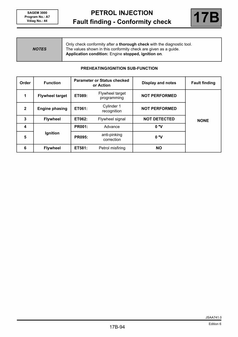
PETROL INJECTIONFault finding - Conformity check 17B
17B-94
SAGEM 3000Program No.: A7
Vdiag No.: 44
PREHEATING/IGNITION SUB-FUNCTION
NOTESOnly check conformity after a thorough check with the diagnostic tool.The values shown in this conformity check are given as a guide.Application condition: Engine stopped, ignition on.
Order FunctionParameter or Status checked
or ActionDisplay and notes Fault finding
1 Flywheel target ET089: Flywheel target programming NOT PERFORMED
NONE
2 Engine phasing ET061: Cylinder 1 recognition
NOT PERFORMED
3 Flywheel ET062: Flywheel signal NOT DETECTED
4
Ignition
PR001: Advance 0 °°°°V
5 PR095:anti-pinking correction
0 °°°°V
6 Flywheel ET581: Petrol misfiring NO
JSAA741.0
Edition 6
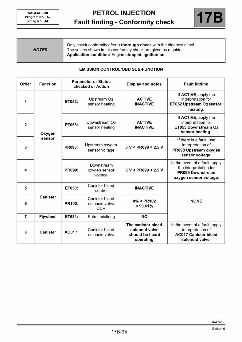
PETROL INJECTIONFault finding - Conformity check 17B
SAGEM 3000Program No.: A7
Vdiag No.: 44
EMISSION CONTROL/OBD SUB-FUNCTION
NOTESOnly check conformity after a thorough check with the diagnostic tool.The values shown in this conformity check are given as a guide.Application condition: Engine stopped, ignition on.
Order FunctionParameter or Status checked or Action
Display and notes Fault finding
1
Oxygen sensor
ET052: Upstream O2
sensor heatingACTIVE
INACTIVE
If ACTIVE, apply the interpretation for
ET052 Upstream O2 sensor heating.
2 ET053: Downstream O2 sensor heating
ACTIVEINACTIVE
If ACTIVE, apply the interpretation for
ET053 Downstream O2 sensor heating.
3 PR098: Upstream oxygen
sensor voltage0 V < PR098 < 2.5 V
If there is a fault, use interpretation of
PR098 Upstream oxygen sensor voltage.
4 PR099:Downstream
oxygen sensor voltage
0 V < PR099 < 2.5 V
In the event of a fault, apply the interpretation for PR099 Downstream
oxygen sensor voltage.
5
Canister
ET050: Canister bleed
controlINACTIVE
NONE6 PR102:
Canister bleed solenoid valve
OCR
0% < PR102 < 99.61%
7 Flywheel ET581: Petrol misfiring NO
8 Canister AC017:Canister bleed solenoid valve
The canister bleed solenoid valve
should be heard operating
In the event of a fault, apply interpretation of
AC017 Canister bleed solenoid valve.
JSAA741.0
Edition 617B-95
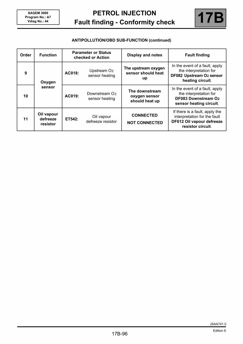
PETROL INJECTIONFault finding - Conformity check 17B
17B-96
SAGEM 3000Program No.: A7
Vdiag No.: 44
ANTIPOLLUTION/OBD SUB-FUNCTION (continued)
Order FunctionParameter or Status checked or Action
Display and notes Fault finding
9
Oxygen sensor
AC018:Upstream O2
sensor heating
The upstream oxygen sensor should heat
up
In the event of a fault, apply the interpretation for
DF082 Upstream O2 sensor heating circuit.
10 AC019:Downstream O2 sensor heating
The downstream oxygen sensor should heat up
In the event of a fault, apply the interpretation for
DF083 Downstream O2 sensor heating circuit.
11Oil vapour defreeze resistor
ET542: Oil vapour
defreeze resistor
CONNECTED
NOT CONNECTED
If there is a fault, apply the interpretation for the fault
DF612 Oil vapour defreeze resistor circuit.
JSAA741.0
Edition 6
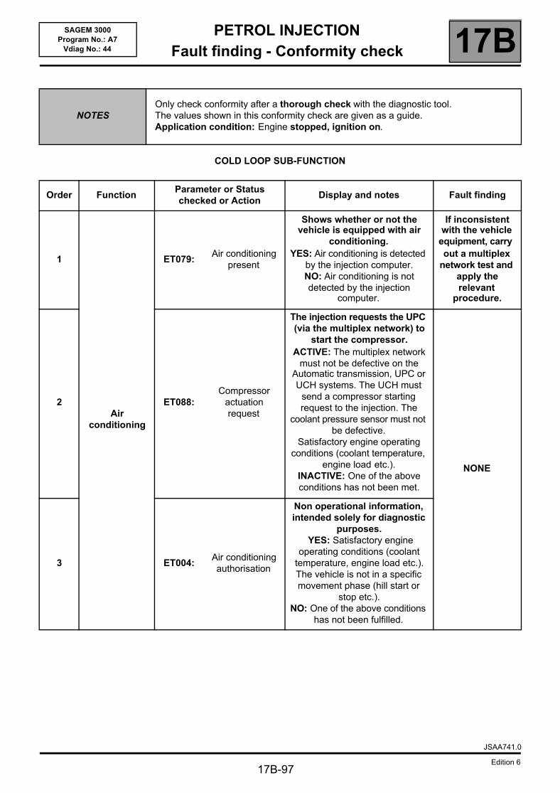
PETROL INJECTIONFault finding - Conformity check 17B
17B-97
SAGEM 3000Program No.: A7
Vdiag No.: 44
COLD LOOP SUB-FUNCTION
NOTESOnly check conformity after a thorough check with the diagnostic tool.The values shown in this conformity check are given as a guide.Application condition: Engine stopped, ignition on.
Order FunctionParameter or Status checked or Action
Display and notes Fault finding
1
Air conditioning
ET079: Air conditioning
present
Shows whether or not the vehicle is equipped with air
conditioning.YES: Air conditioning is detected
by the injection computer.NO: Air conditioning is not detected by the injection
computer.
If inconsistent with the vehicle
equipment, carry out a multiplex
network test and apply the relevant
procedure.
2 ET088: Compressor
actuation request
The injection requests the UPC (via the multiplex network) to
start the compressor.ACTIVE: The multiplex network
must not be defective on the Automatic transmission, UPC or UCH systems. The UCH must
send a compressor starting request to the injection. The
coolant pressure sensor must not be defective.
Satisfactory engine operating conditions (coolant temperature,
engine load etc.).INACTIVE: One of the above conditions has not been met.
NONE
3 ET004: Air conditioning authorisation
Non operational information, intended solely for diagnostic
purposes. YES: Satisfactory engine
operating conditions (coolant temperature, engine load etc.). The vehicle is not in a specific movement phase (hill start or
stop etc.).NO: One of the above conditions
has not been fulfilled.
JSAA741.0
Edition 6
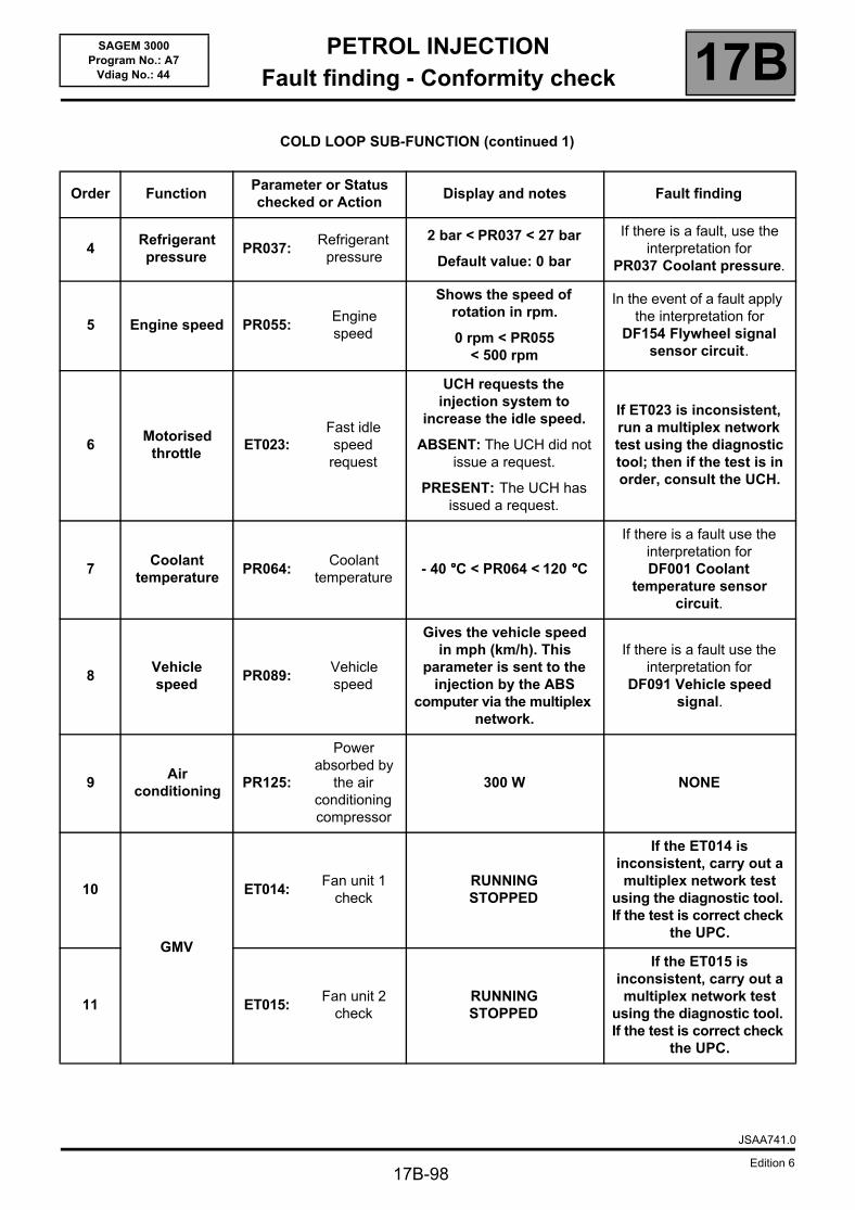
PETROL INJECTIONFault finding - Conformity check 17B
17B-98
SAGEM 3000Program No.: A7
Vdiag No.: 44
COLD LOOP SUB-FUNCTION (continued 1)
Order FunctionParameter or Status checked or Action
Display and notes Fault finding
4Refrigerant pressure
PR037:Refrigerant
pressure
2 bar < PR037 < 27 bar
Default value: 0 bar
If there is a fault, use the interpretation for
PR037 Coolant pressure.
5 Engine speed PR055:Engine speed
Shows the speed of rotation in rpm.
0 rpm < PR055 < 500 rpm
In the event of a fault apply the interpretation for
DF154 Flywheel signal sensor circuit.
6Motorised
throttle ET023:
Fast idle speed
request
UCH requests the injection system to
increase the idle speed.
ABSENT: The UCH did not issue a request.
PRESENT: The UCH has issued a request.
If ET023 is inconsistent, run a multiplex network test using the diagnostic tool; then if the test is in order, consult the UCH.
7Coolant
temperaturePR064:
Coolant temperature
- 40 °°°°C < PR064 < 120 °°°°C
If there is a fault use the interpretation for DF001 Coolant
temperature sensor circuit.
8Vehicle speed
PR089:Vehicle speed
Gives the vehicle speed in mph (km/h). This
parameter is sent to the injection by the ABS
computer via the multiplex network.
If there is a fault use the interpretation for
DF091 Vehicle speed signal.
9Air
conditioningPR125:
Power absorbed by
the air conditioning compressor
300 W NONE
10
GMV
ET014: Fan unit 1
checkRUNNING STOPPED
If the ET014 is inconsistent, carry out a multiplex network test
using the diagnostic tool. If the test is correct check
the UPC.
11 ET015: Fan unit 2
checkRUNNING STOPPED
If the ET015 is inconsistent, carry out a multiplex network test
using the diagnostic tool. If the test is correct check
the UPC.
JSAA741.0
Edition 6
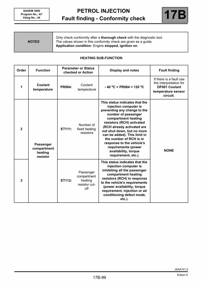
PETROL INJECTIONFault finding - Conformity check 17B
17B-99
SAGEM 3000Program No.: A7
Vdiag No.: 44
HEATING SUB-FUNCTION
NOTESOnly check conformity after a thorough check with the diagnostic tool.The values shown in this conformity check are given as a guide.Application condition: Engine stopped, ignition on.
Order FunctionParameter or Status checked or Action
Display and notes Fault finding
1Coolant
temperaturePR064:
Coolant temperature
- 40 °°°°C < PR064 < 120 °°°°C
If there is a fault use the interpretation for
DF001 Coolant temperature sensor
circuit.
2
Passenger compartment
heating resistor
ET111: Number of
fixed heating resistors
This status indicates that the injection computer is
preventing any change to the number of passenger compartment heating
resistors (RCH) activated (RCH already activated are
not shut down, but no more can be added). This limit in
the number of RCH is in response to the vehicle's
requirements (power availability, torque requirement, etc.).
NONE
3 ET112:
Passenger compartment
heating resistor cut-
off
This status indicates that the injection computer is
inhibiting all the passenger compartment heating
resistors (RCH) in response to the vehicle's requirements
(power availability, torque requirement, injection or air conditioning defect mode,
etc.).
JSAA741.0
Edition 6
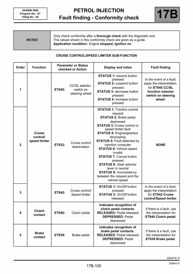
PETROL INJECTIONFault finding - Conformity check 17B
17B-100
SAGEM 3000Program No.: A7
Vdiag No.: 44
CRUISE CONTROL/SPEED LIMITER SUB-FUNCTION
NOTESOnly check conformity after a thorough check with the diagnostic tool.The values shown in this conformity check are given as a guide.Application condition: Engine stopped, ignition on.
Order FunctionParameter or Status checked or Action
Display and notes Fault finding
1
Cruise control/
speed limiter
ET045: CC/SL selector
switch on steering wheel
STATUS 1: resume button pressed
STATUS 2: suspend button pressed
STATUS 3: decrease button pressed
STATUS 4: increase button pressed
In the event of a fault, apply the interpretation
for ET045 CC/SL function selector
switch on steering wheel.
2 ET032: Cruise control deactivation
STATUS 1: Traction control request
STATUS 2: Brake pedal depressed
STATUS 3: Cruise control or speed limiter fault
STATUS 4: Engine/gearbox decoupling
STATUS 5: Fault detected by injection computer
STATUS 6: Vehicle speed invalid
STATUS 7: Cancel button pressed
STATUS 8: Gear selector lever in neutral
STATUS 9: Inconsistency between the request and the
vehicle speed
NONE
3 ET042: Cruise control/Speed limiter
STATUS 1: On/Off button pressed
STATUS 2: On/Off button released
In the event of a fault, apply the interpretation
for ET042 Cruise control/Speed limiter.
4Clutch contact
ET040: Clutch pedal
Indicates recognition of clutch pedal contacts.
RELEASED: Pedal releasedDEPRESSED: Pedal
depressed
If there is a fault, use the interpretation for
ET040 Clutch pedal.
5Brake
contactET039: Brake pedal
Indicates recognition of brake pedal contacts.
RELEASED: Pedal releasedDEPRESSED: Pedal
depressed
If there is a fault, use the interpretation for ET039 Brake pedal.
JSAA741.0
Edition 6

PETROL INJECTIONFault finding - Conformity check 17B
17B-101
SAGEM 3000Program No.: A7
Vdiag No.: 44
START SUB-FUNCTION
NOTESOnly check conformity after a thorough check with the diagnostic tool.The values shown in this conformity check are given as a guide.Application condition: Engine stopped, ignition on.
Order FunctionParameter or Status checked or Action
Display and notes
Fault finding
1 Starting ET076: Starting AUTHORISED
The authorisation to start is given once the fuel pump is
pressurised and if the motorised throttle has
completed its stop and limp-home position programming
phase.
2Actuator relay
controlET048:
Actuator relay control
ACTIVE
INACTIVE
If ACTIVE apply the interpretation of DF084 Actuator relay control
circuit.
3 Battery voltage PR071:Computer feed
voltage11 V < PR071
< 15 V
If there is a fault, use interpretation of
PR071 Computer supply voltage.
JSAA741.0
Edition 6
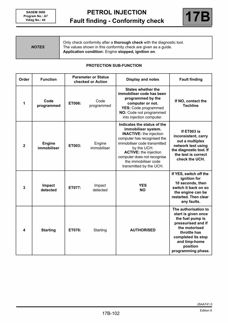
PETROL INJECTIONFault finding - Conformity check 17B
17B-102
SAGEM 3000Program No.: A7
Vdiag No.: 44
PROTECTION SUB-FUNCTION
NOTESOnly check conformity after a thorough check with the diagnostic tool.The values shown in this conformity check are given as a guide.Application condition: Engine stopped, ignition on.
Order FunctionParameter or Status checked or Action
Display and notes Fault finding
1Code
programmedET006:
Code programmed
States whether the immobiliser code has been
programmed by the computer or not.
YES: Code programmedNO: Code not programmed
into injection computer.
If NO, contact the Techline
2Engine
immobiliserET003:
Engine immobiliser
Indicates the status of the immobiliser system.
INACTIVE: the injection computer has recognised the immobiliser code transmitted
by the UCH.ACTIVE: the injection
computer does not recognise the immobiliser code
transmitted by the UCH.
If ET003 is inconsistent, carry
out a multiplex network test using
the diagnostic tool. If the test is correct check the UCH.
3Impact
detectedET077:
Impact detected
YESNO
If YES, switch off the ignition for
10 seconds, then switch it back on so the engine can be
restarted. Then clear any faults.
4 Starting ET076: Starting AUTHORISED
The authorisation to start is given once the fuel pump is
pressurised and if the motorised throttle has
completed its stop and limp-home
position programming phase.
JSAA741.0
Edition 6
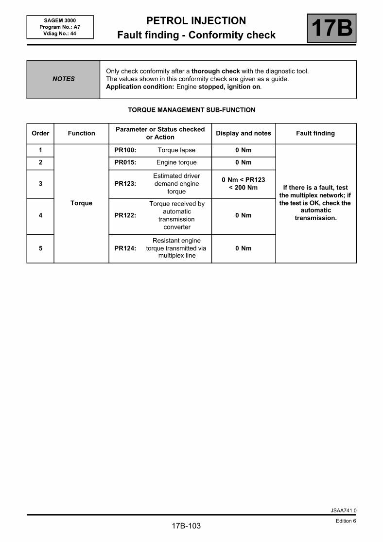
PETROL INJECTIONFault finding - Conformity check 17B
17B-103
SAGEM 3000Program No.: A7
Vdiag No.: 44
TORQUE MANAGEMENT SUB-FUNCTION
NOTESOnly check conformity after a thorough check with the diagnostic tool.The values shown in this conformity check are given as a guide.Application condition: Engine stopped, ignition on.
Order FunctionParameter or Status checked
or ActionDisplay and notes Fault finding
1
Torque
PR100: Torque lapse 0 Nm
If there is a fault, test the multiplex network; if the test is OK, check the
automatic transmission.
2 PR015: Engine torque 0 Nm
3 PR123:Estimated driver demand engine
torque
0 Nm < PR123 < 200 Nm
4 PR122:
Torque received by automatic
transmission converter
0 Nm
5 PR124:Resistant engine
torque transmitted via multiplex line
0 Nm
JSAA741.0
Edition 6
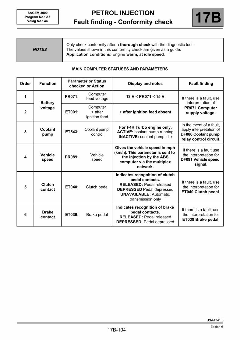
PETROL INJECTIONFault finding - Conformity check 17B
17B-104
SAGEM 3000Program No.: A7
Vdiag No.: 44
MAIN COMPUTER STATUSES AND PARAMETERS
NOTESOnly check conformity after a thorough check with the diagnostic tool.The values shown in this conformity check are given as a guide. Application conditions: Engine warm, at idle speed.
Order FunctionParameter or Status checked or Action
Display and notes Fault finding
1
Battery voltage
PR071:Computer
feed voltage 13 V < PR071 < 15 V If there is a fault, use interpretation of
PR071 Computer supply voltage.2 ET001:
Computer + after
ignition feed+ after ignition feed absent
3Coolant pump
ET543: Coolant pump
control
For F4R Turbo engine only.ACTIVE: coolant pump runningINACTIVE: coolant pump idle
In the event of a fault, apply interpretation of DF086 Coolant pump relay control circuit.
4 Vehicle speed
PR089: Vehicle speed
Gives the vehicle speed in mph (km/h). This parameter is sent to
the injection by the ABS computer via the multiplex
network.
If there is a fault use the interpretation for
DF091 Vehicle speed signal.
5Clutch contact
ET040: Clutch pedal
Indicates recognition of clutch pedal contacts.
RELEASED: Pedal releasedDEPRESSED Pedal depressed
UNAVAILABLE: Automatic transmission only
If there is a fault, use the interpretation for
ET040 Clutch pedal.
6Brake
contactET039: Brake pedal
Indicates recognition of brake pedal contacts.
RELEASED: Pedal releasedDEPRESSED: Pedal depressed
If there is a fault, use the interpretation for ET039 Brake pedal.
JSAA741.0
Edition 6
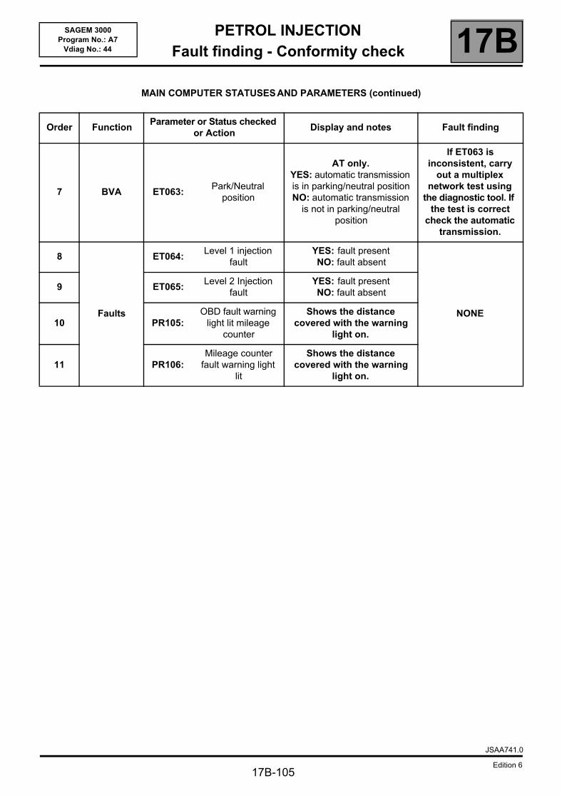
PETROL INJECTIONFault finding - Conformity check 17B
17B-105
SAGEM 3000Program No.: A7
Vdiag No.: 44
MAIN COMPUTER STATUSES AND PARAMETERS (continued)
Order FunctionParameter or Status checked
or ActionDisplay and notes Fault finding
7 BVA ET063: Park/Neutral
position
AT only.YES: automatic transmission is in parking/neutral positionNO: automatic transmission
is not in parking/neutral position
If ET063 is inconsistent, carry
out a multiplex network test using
the diagnostic tool. If the test is correct
check the automatic transmission.
8
Faults
ET064: Level 1 injection
faultYES: fault presentNO: fault absent
NONE
9 ET065: Level 2 Injection
faultYES: fault presentNO: fault absent
10 PR105:OBD fault warning
light lit mileage counter
Shows the distance covered with the warning
light on.
11 PR106:Mileage counter
fault warning light lit
Shows the distance covered with the warning
light on.
JSAA741.0
Edition 6
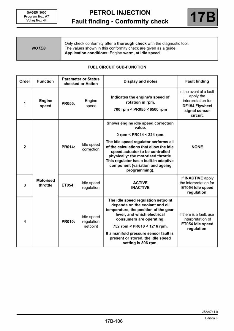
PETROL INJECTIONFault finding - Conformity check 17B
17B-106
SAGEM 3000Program No.: A7
Vdiag No.: 44
FUEL CIRCUIT SUB-FUNCTION
NOTESOnly check conformity after a thorough check with the diagnostic tool.The values shown in this conformity check are given as a guide. Application conditions: Engine warm, at idle speed.
Order FunctionParameter or Status checked or Action
Display and notes Fault finding
1Engine speed
PR055:Engine speed
Indicates the engine's speed of rotation in rpm.
700 rpm < PR055 < 6500 rpm
In the event of a fault apply the
interpretation for DF154 Flywheel signal sensor
circuit.
2
Motorised throttle
PR014:Idle speed correction
Shows engine idle speed correction value.
0 rpm < PR014 < 224 rpm.
The idle speed regulator performs all of the calculations that allow the idle
speed actuator to be controlled physically: the motorised throttle.
This regulator has a built-in adaptive component (variation and ageing
programming).
NONE
3 ET054: Idle speed regulation
ACTIVEINACTIVE
If INACTIVE apply the interpretation for ET054 Idle speed
regulation.
4 PR010:Idle speed regulation setpoint
The idle speed regulation setpoint depends on the coolant and oil
temperature, the position of the gear lever, and which electrical consumers are operating.
752 rpm < PR010 < 1216 rpm.
If a manifold pressure sensor fault is present or stored, the idle speed
setting is 896 rpm.
If there is a fault, use interpretation of
ET054 Idle speed regulation.
JSAA741.0
Edition 6
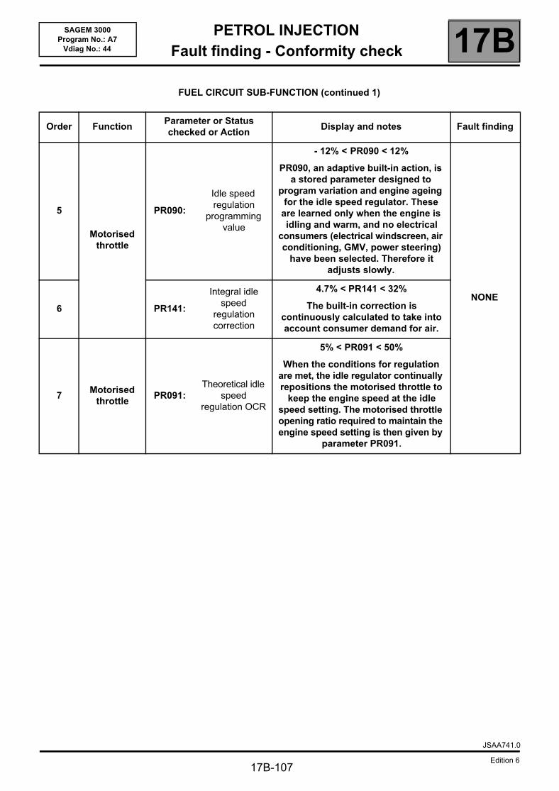
PETROL INJECTIONFault finding - Conformity check 17B
17B-107
SAGEM 3000Program No.: A7
Vdiag No.: 44
FUEL CIRCUIT SUB-FUNCTION (continued 1)
Order FunctionParameter or Status checked or Action
Display and notes Fault finding
5
Motorised throttle
PR090:
Idle speed regulation
programming value
- 12% < PR090 < 12%
PR090, an adaptive built-in action, is a stored parameter designed to
program variation and engine ageing for the idle speed regulator. These
are learned only when the engine is idling and warm, and no electrical
consumers (electrical windscreen, air conditioning, GMV, power steering)
have been selected. Therefore it adjusts slowly.
NONE6 PR141:
Integral idle speed
regulation correction
4.7% < PR141 < 32%
The built-in correction is continuously calculated to take into account consumer demand for air.
7Motorised
throttle PR091:
Theoretical idle speed
regulation OCR
5% < PR091 < 50%
When the conditions for regulation are met, the idle regulator continually repositions the motorised throttle to
keep the engine speed at the idle speed setting. The motorised throttle opening ratio required to maintain the engine speed setting is then given by
parameter PR091.
JSAA741.0
Edition 6
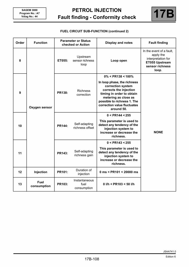
PETROL INJECTIONFault finding - Conformity check 17B
17B-108
SAGEM 3000Program No.: A7
Vdiag No.: 44
FUEL CIRCUIT SUB-FUNCTION (continued 2)
Order FunctionParameter or Status checked or Action
Display and notes Fault finding
8
Oxygen sensor
ET055: Upstream
sensor richness loop
Loop open
In the event of a fault, apply the
interpretation for ET055 Upstream sensor richness
loop.
9 PR138:Richness correction
0% < PR138 < 100%
In loop phase, the richness correction system
corrects the injection timing in order to obtain
metering as close as possible to richness 1. The correction value fluctuates
around 50.
NONE
10 PR144: Self-adapting
richness offset
0 < PR144 < 255
This parameter is used to detect any tendency of the
injection system to increase or decrease the
richness.
11 PR143: Self-adapting richness gain
0 < PR143 < 255
This parameter is used to detect any tendency of the
injection system to increase or decrease the
richness.
12 Injection PR101:Duration of
injection0 ms < PR101 < 20000 ms
13Fuel
consumptionPR103:
Instantaneous fuel
consumption0 l/h < PR103 < 50 l/h
JSAA741.0
Edition 6
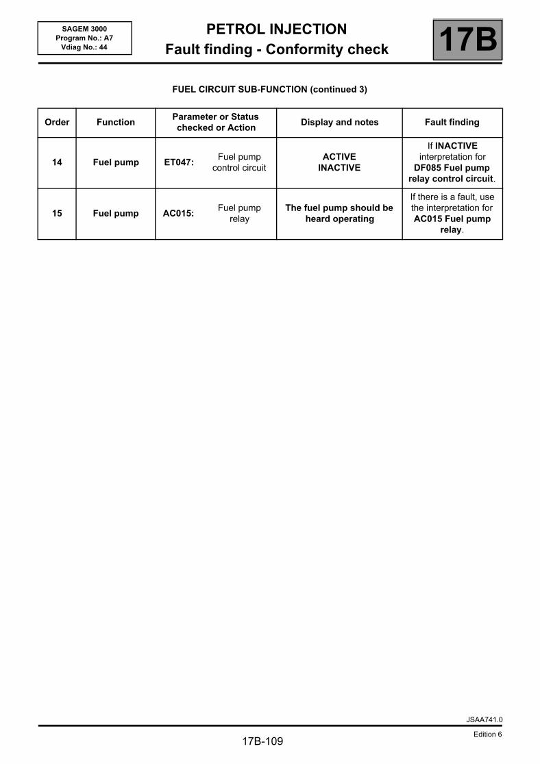
PETROL INJECTIONFault finding - Conformity check 17B
17B-109
SAGEM 3000Program No.: A7
Vdiag No.: 44
FUEL CIRCUIT SUB-FUNCTION (continued 3)
Order FunctionParameter or Status checked or Action
Display and notes Fault finding
14 Fuel pump ET047: Fuel pump
control circuitACTIVE
INACTIVE
If INACTIVE interpretation for
DF085 Fuel pump relay control circuit.
15 Fuel pump AC015: Fuel pump
relayThe fuel pump should be
heard operating
If there is a fault, use the interpretation for AC015 Fuel pump
relay.
JSAA741.0
Edition 6
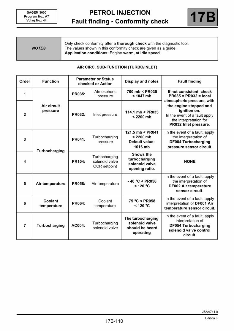
PETROL INJECTIONFault finding - Conformity check 17B
17B-110
SAGEM 3000Program No.: A7
Vdiag No.: 44
AIR CIRC. SUB-FUNCTION (TURBO/INLET)
NOTESOnly check conformity after a thorough check with the diagnostic tool.The values shown in this conformity check are given as a guide. Application conditions: Engine warm, at idle speed.
Order FunctionParameter or Status checked or Action
Display and notes Fault finding
1
Air circuit pressure
PR035:Atmospheric
pressure700 mb < PR035
< 1047 mbIf not consistent, check PR035 = PR032 = local
atmospheric pressure, with the engine stopped and
ignition on.In the event of a fault apply
the interpretation for PR032 Inlet pressure.
2 PR032: Inlet pressure114.1 mb < PR035
< 2200 mb
3
Turbocharging
PR041:Turbocharging
pressure
121.5 mb < PR041 < 2200 mb
Default value: 1016 mb
In the event of a fault, apply the interpretation of
DF004 Turbocharging pressure sensor circuit.
4 PR104:Turbocharging solenoid valve OCR setpoint
Shows the turbocharging solenoid valve opening ratio.
NONE
5 Air temperature PR058: Air temperature- 40 °°°°C < PR058
< 120 °°°°C
In the event of a fault, apply the interpretation of
DF002 Air temperature sensor circuit.
6Coolant
temperaturePR064:
Coolant temperature
75 °°°°C < PR058 < 120 °°°°C
In the event of a fault, apply interpretation of DF001 Air
temperature sensor circuit.
7 Turbocharging AC004:Turbocharging solenoid valve
The turbocharging solenoid valve
should be heard operating
In the event of a fault, apply interpretation of
DF054 Turbocharging solenoid valve control
circuit.
JSAA741.0
Edition 6
PETROL INJECTIONFault finding - Conformity check 17B
17B-111
SAGEM 3000Program No.: A7
Vdiag No.: 44
DRIVER PARAMETERS SUB-FUNCTION
NOTESOnly check conformity after a thorough check with the diagnostic tool.The values shown in this conformity check are given as a guide. Application conditions: Engine warm, at idle speed.
Order FunctionParameter or Status checked
or ActionDisplay and
notesFault finding
1
Motorised throttle
ET085: Motorised throttle in
defect mode
NOSTATUS 0STATUS 1STATUS 2STATUS 3STATUS 4STATUS 5
NONE
2 ET051: Throttle stop programming
PERFORMED
Run command RZ005 Programming. If the
parameters and statuses are still incorrect, contact the
Techline.
3 PR097: Motorised throttle
lower stop programmed value
5.96% < PR097 < 13.96%
4 PR113:Throttle lower stop after applying offset
5.96% < PR113 < 13.96%
5 PR096: Motorised throttle
upper stop programmed value
PR096 = 87.99%
6 ET082: Motorised throttle
position
OPENCLOSED
NOT DETECTED
If NOT DETECTED, apply interpretation of
ET082 Motorised throttle valve position.
7 PR118:Motorised throttle position gang 1
No load = 4%Full load =
99.02%
If there is a fault, use the interpretation for
DF095 Throttle potentiometer circuit gang 1.
8 PR119:Motorised throttle position gang 2
No load = 4%Full load = 100%
If there is a fault, use the interpretation for
DF096 Throttle potentiometer circuit gang 2.
9 PR116:Motorised throttle corrected position
setpoint
No load = 0%Full load = 83%
NONE
10 PR111:Motorised throttle position corrected
value
No load = 0%Full load = 83%
JSAA741.0
Edition 6
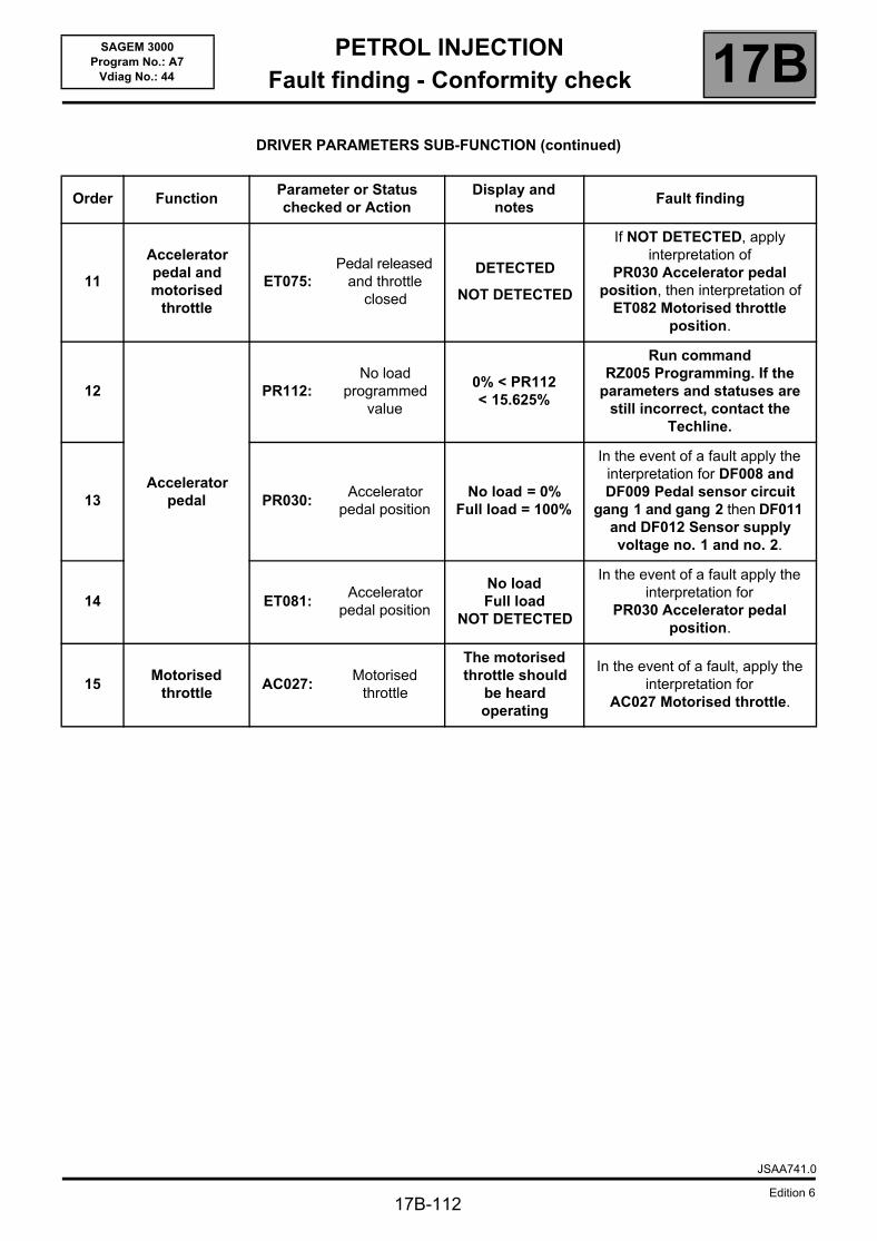
PETROL INJECTIONFault finding - Conformity check 17B
17B-112
SAGEM 3000Program No.: A7
Vdiag No.: 44
DRIVER PARAMETERS SUB-FUNCTION (continued)
Order FunctionParameter or Status checked or Action
Display and notes
Fault finding
11
Accelerator pedal and motorised
throttle
ET075: Pedal released
and throttle closed
DETECTED
NOT DETECTED
If NOT DETECTED, apply interpretation of
PR030 Accelerator pedal position, then interpretation of
ET082 Motorised throttle position.
12
Accelerator pedal
PR112:No load
programmed value
0% < PR112 < 15.625%
Run command RZ005 Programming. If the
parameters and statuses are still incorrect, contact the
Techline.
13 PR030:Accelerator
pedal positionNo load = 0%
Full load = 100%
In the event of a fault apply the interpretation for DF008 and DF009 Pedal sensor circuit
gang 1 and gang 2 then DF011 and DF012 Sensor supply voltage no. 1 and no. 2.
14 ET081: Accelerator
pedal position
No load Full load
NOT DETECTED
In the event of a fault apply the interpretation for
PR030 Accelerator pedal position.
15Motorised
throttle AC027:
Motorised throttle
The motorised throttle should
be heard operating
In the event of a fault, apply the interpretation for
AC027 Motorised throttle.
JSAA741.0
Edition 6
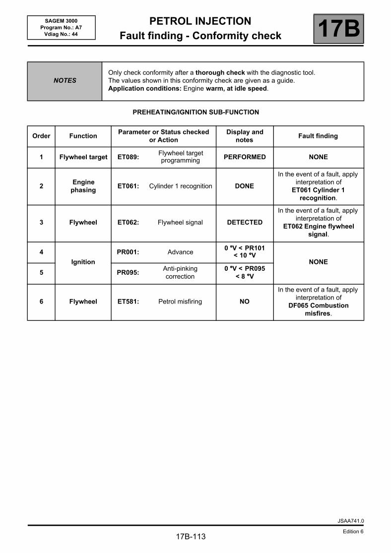
PETROL INJECTIONFault finding - Conformity check 17B
17B-113
SAGEM 3000Program No.: A7
Vdiag No.: 44
PREHEATING/IGNITION SUB-FUNCTION
NOTESOnly check conformity after a thorough check with the diagnostic tool.The values shown in this conformity check are given as a guide. Application conditions: Engine warm, at idle speed.
Order FunctionParameter or Status checked
or ActionDisplay and
notesFault finding
1 Flywheel target ET089: Flywheel target programming PERFORMED NONE
2Engine
phasingET061: Cylinder 1 recognition DONE
In the event of a fault, apply interpretation of
ET061 Cylinder 1 recognition.
3 Flywheel ET062: Flywheel signal DETECTED
In the event of a fault, apply interpretation of
ET062 Engine flywheel signal.
4
Ignition
PR001: Advance0 °°°°V < PR101
< 10 °°°°VNONE
5 PR095:Anti-pinking correction
0 °°°°V < PR095 < 8 °°°°V
6 Flywheel ET581: Petrol misfiring NO
In the event of a fault, apply interpretation of
DF065 Combustion misfires.
JSAA741.0
Edition 6
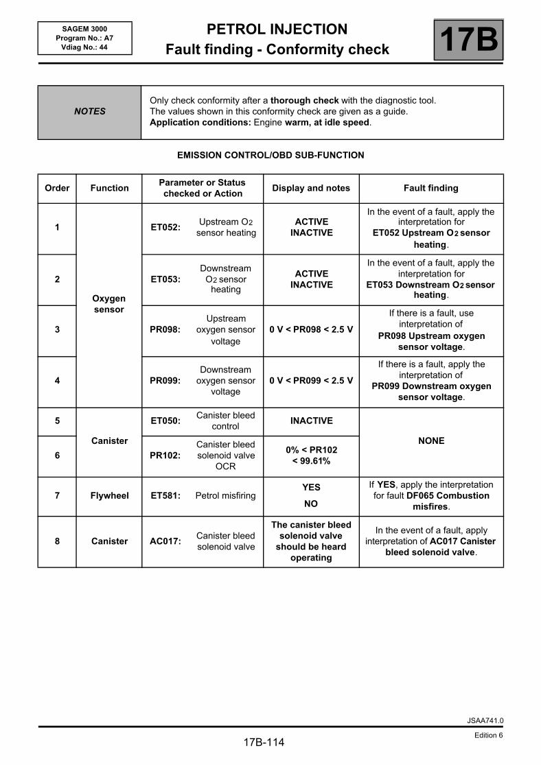
PETROL INJECTIONFault finding - Conformity check 17B
17B-114
SAGEM 3000Program No.: A7
Vdiag No.: 44
EMISSION CONTROL/OBD SUB-FUNCTION
NOTESOnly check conformity after a thorough check with the diagnostic tool.The values shown in this conformity check are given as a guide. Application conditions: Engine warm, at idle speed.
Order FunctionParameter or Status checked or Action
Display and notes Fault finding
1
Oxygen sensor
ET052: Upstream O2
sensor heatingACTIVE
INACTIVE
In the event of a fault, apply the interpretation for
ET052 Upstream O2 sensor heating.
2 ET053: Downstream
O2 sensor heating
ACTIVEINACTIVE
In the event of a fault, apply the interpretation for
ET053 Downstream O2 sensor heating.
3 PR098: Upstream
oxygen sensor voltage
0 V < PR098 < 2.5 V
If there is a fault, use interpretation of
PR098 Upstream oxygen sensor voltage.
4 PR099:Downstream
oxygen sensor voltage
0 V < PR099 < 2.5 V
If there is a fault, apply the interpretation of
PR099 Downstream oxygen sensor voltage.
5
Canister
ET050: Canister bleed
controlINACTIVE
NONE
6 PR102:Canister bleed solenoid valve
OCR
0% < PR102 < 99.61%
7 Flywheel ET581: Petrol misfiringYES
NO
If YES, apply the interpretation for fault DF065 Combustion
misfires.
8 Canister AC017:Canister bleed solenoid valve
The canister bleed solenoid valve
should be heard operating
In the event of a fault, apply interpretation of AC017 Canister
bleed solenoid valve.
JSAA741.0
Edition 6
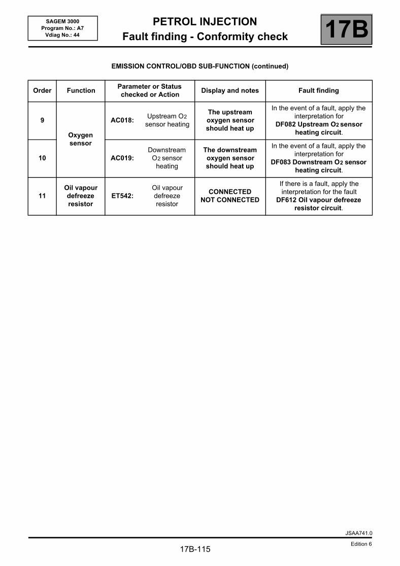
PETROL INJECTIONFault finding - Conformity check 17B
17B-115
SAGEM 3000Program No.: A7
Vdiag No.: 44
EMISSION CONTROL/OBD SUB-FUNCTION (continued)
Order FunctionParameter or Status checked or Action
Display and notes Fault finding
9
Oxygen sensor
AC018:Upstream O2
sensor heating
The upstream oxygen sensor should heat up
In the event of a fault, apply the interpretation for
DF082 Upstream O2 sensor heating circuit.
10 AC019:Downstream
O2 sensor heating
The downstream oxygen sensor should heat up
In the event of a fault, apply the interpretation for
DF083 Downstream O2 sensor heating circuit.
11Oil vapour defreeze resistor
ET542: Oil vapour defreeze resistor
CONNECTEDNOT CONNECTED
If there is a fault, apply the interpretation for the fault
DF612 Oil vapour defreeze resistor circuit.
JSAA741.0
Edition 6
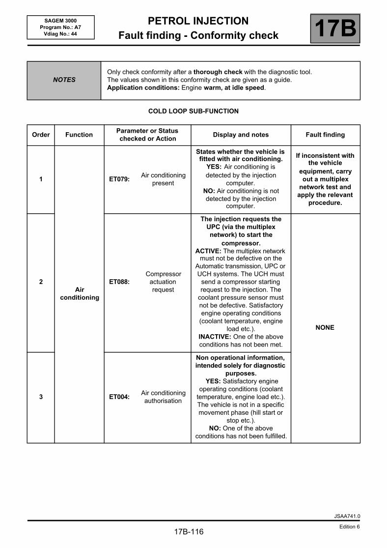
PETROL INJECTIONFault finding - Conformity check 17B
17B-116
SAGEM 3000Program No.: A7
Vdiag No.: 44
COLD LOOP SUB-FUNCTION
NOTESOnly check conformity after a thorough check with the diagnostic tool.The values shown in this conformity check are given as a guide. Application conditions: Engine warm, at idle speed.
Order FunctionParameter or Status checked or Action
Display and notes Fault finding
1
Air conditioning
ET079: Air conditioning
present
States whether the vehicle is fitted with air conditioning.
YES: Air conditioning is detected by the injection
computer.NO: Air conditioning is not detected by the injection
computer.
If inconsistent with the vehicle
equipment, carry out a multiplex
network test and apply the relevant
procedure.
2 ET088: Compressor
actuation request
The injection requests the UPC (via the multiplex network) to start the
compressor.ACTIVE: The multiplex network
must not be defective on the Automatic transmission, UPC or UCH systems. The UCH must
send a compressor starting request to the injection. The
coolant pressure sensor must not be defective. Satisfactory engine operating conditions
(coolant temperature, engine load etc.).
INACTIVE: One of the above conditions has not been met.
NONE
3 ET004: Air conditioning authorisation
Non operational information, intended solely for diagnostic
purposes. YES: Satisfactory engine
operating conditions (coolant temperature, engine load etc.). The vehicle is not in a specific movement phase (hill start or
stop etc.).NO: One of the above
conditions has not been fulfilled.
JSAA741.0
Edition 6
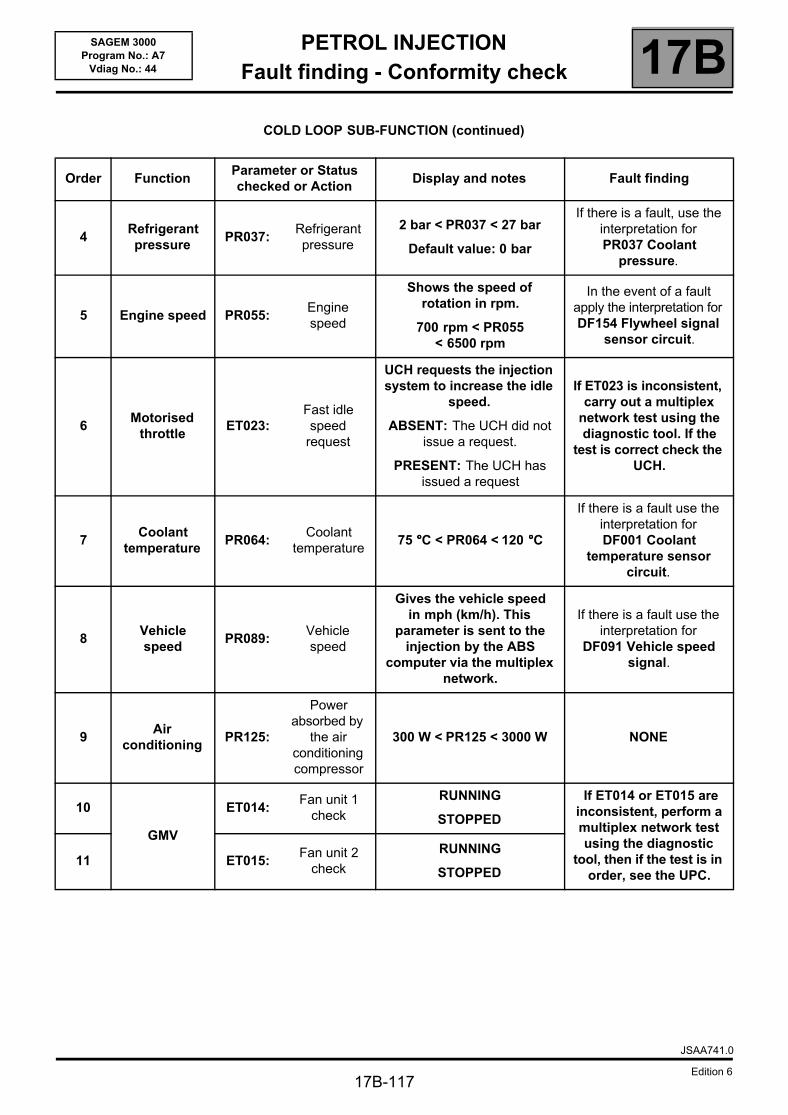
PETROL INJECTIONFault finding - Conformity check 17B
17B-117
SAGEM 3000Program No.: A7
Vdiag No.: 44
COLD LOOP SUB-FUNCTION (continued)
Order FunctionParameter or Status checked or Action
Display and notes Fault finding
4Refrigerant pressure
PR037:Refrigerant pressure
2 bar < PR037 < 27 bar
Default value: 0 bar
If there is a fault, use the interpretation for PR037 Coolant
pressure.
5 Engine speed PR055: Engine speed
Shows the speed of rotation in rpm.
700 rpm < PR055 < 6500 rpm
In the event of a fault apply the interpretation for DF154 Flywheel signal
sensor circuit.
6Motorised
throttle ET023:
Fast idle speed
request
UCH requests the injection system to increase the idle
speed.
ABSENT: The UCH did not issue a request.
PRESENT: The UCH has issued a request
If ET023 is inconsistent, carry out a multiplex
network test using the diagnostic tool. If the
test is correct check the UCH.
7Coolant
temperaturePR064:
Coolant temperature
75 °°°°C < PR064 < 120 °°°°C
If there is a fault use the interpretation for DF001 Coolant
temperature sensor circuit.
8Vehicle speed
PR089:Vehicle speed
Gives the vehicle speed in mph (km/h). This
parameter is sent to the injection by the ABS
computer via the multiplex network.
If there is a fault use the interpretation for
DF091 Vehicle speed signal.
9Air
conditioningPR125:
Power absorbed by
the air conditioning compressor
300 W < PR125 < 3000 W NONE
10
GMV
ET014: Fan unit 1
check
RUNNING
STOPPED
If ET014 or ET015 are inconsistent, perform a multiplex network test using the diagnostic
tool, then if the test is in order, see the UPC.
11 ET015: Fan unit 2
check
RUNNING
STOPPED
JSAA741.0
Edition 6
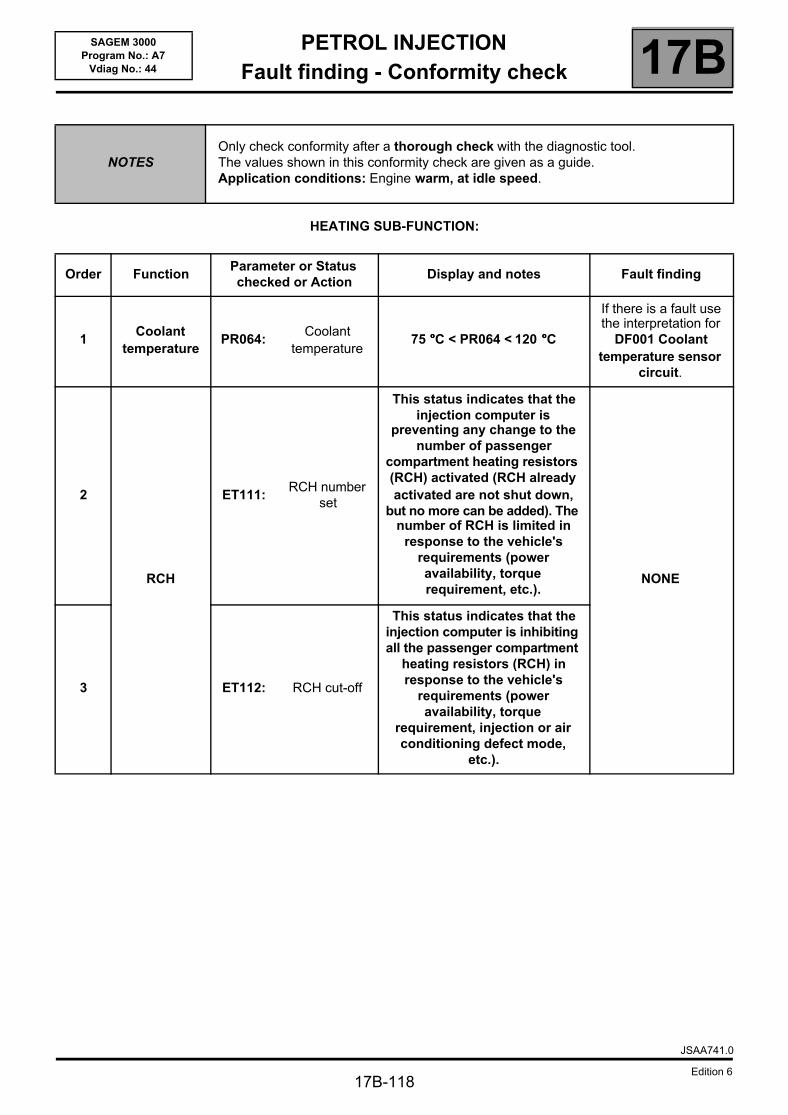
PETROL INJECTIONFault finding - Conformity check 17B
17B-118
SAGEM 3000Program No.: A7
Vdiag No.: 44
HEATING SUB-FUNCTION:
NOTESOnly check conformity after a thorough check with the diagnostic tool.The values shown in this conformity check are given as a guide. Application conditions: Engine warm, at idle speed.
Order FunctionParameter or Status checked or Action
Display and notes Fault finding
1Coolant
temperaturePR064:
Coolant temperature
75 °°°°C < PR064 < 120 °°°°C
If there is a fault use the interpretation for
DF001 Coolant temperature sensor
circuit.
2
RCH
ET111: RCH number
set
This status indicates that the injection computer is
preventing any change to the number of passenger
compartment heating resistors (RCH) activated (RCH already activated are not shut down,
but no more can be added). The number of RCH is limited in
response to the vehicle's requirements (power availability, torque requirement, etc.).
NONE
3 ET112: RCH cut-off
This status indicates that the injection computer is inhibiting all the passenger compartment
heating resistors (RCH) in response to the vehicle's
requirements (power availability, torque
requirement, injection or air conditioning defect mode,
etc.).
JSAA741.0
Edition 6
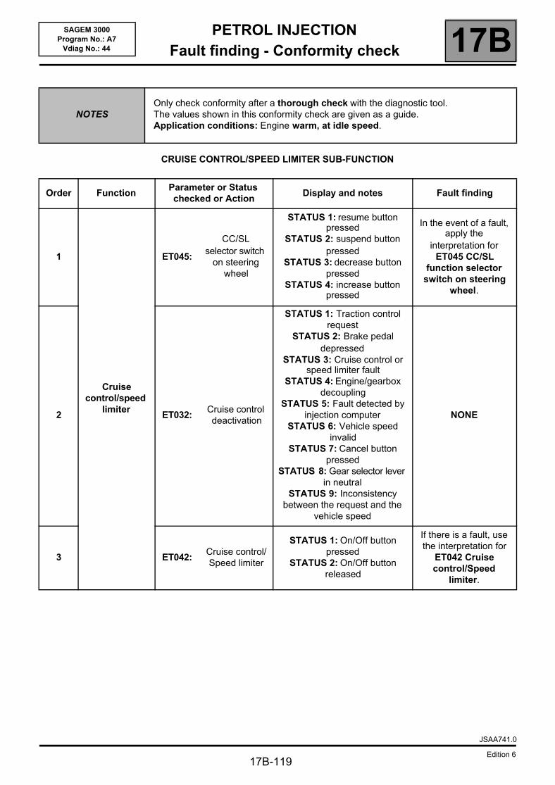
PETROL INJECTIONFault finding - Conformity check 17B
17B-119
SAGEM 3000Program No.: A7
Vdiag No.: 44
CRUISE CONTROL/SPEED LIMITER SUB-FUNCTION
NOTESOnly check conformity after a thorough check with the diagnostic tool.The values shown in this conformity check are given as a guide. Application conditions: Engine warm, at idle speed.
Order FunctionParameter or Status checked or Action
Display and notes Fault finding
1
Cruise control/speed
limiter
ET045:
CC/SL selector switch
on steering wheel
STATUS 1: resume button pressed
STATUS 2: suspend button pressed
STATUS 3: decrease button pressed
STATUS 4: increase button pressed
In the event of a fault, apply the
interpretation for ET045 CC/SL
function selector switch on steering
wheel.
2 ET032: Cruise control deactivation
STATUS 1: Traction control request
STATUS 2: Brake pedal depressed
STATUS 3: Cruise control or speed limiter fault
STATUS 4: Engine/gearbox decoupling
STATUS 5: Fault detected by injection computer
STATUS 6: Vehicle speed invalid
STATUS 7: Cancel button pressed
STATUS 8: Gear selector lever in neutral
STATUS 9: Inconsistency between the request and the
vehicle speed
NONE
3 ET042: Cruise control/Speed limiter
STATUS 1: On/Off button pressed
STATUS 2: On/Off button released
If there is a fault, use the interpretation for
ET042 Cruise control/Speed
limiter.
JSAA741.0
Edition 6
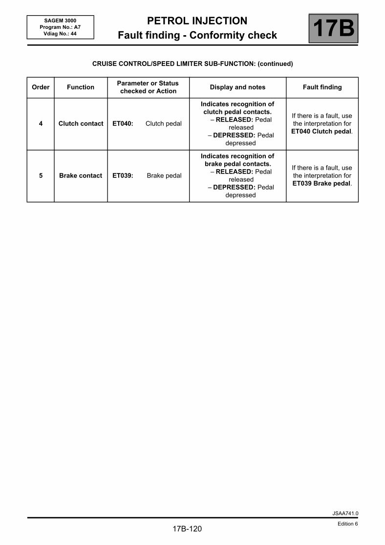
PETROL INJECTIONFault finding - Conformity check 17B
17B-120
SAGEM 3000Program No.: A7
Vdiag No.: 44
CRUISE CONTROL/SPEED LIMITER SUB-FUNCTION: (continued)
Order FunctionParameter or Status checked or Action
Display and notes Fault finding
4 Clutch contact ET040: Clutch pedal
Indicates recognition of clutch pedal contacts.
– RELEASED: Pedal released
– DEPRESSED: Pedal depressed
If there is a fault, use the interpretation for
ET040 Clutch pedal.
5 Brake contact ET039: Brake pedal
Indicates recognition of brake pedal contacts.
– RELEASED: Pedal released
– DEPRESSED: Pedal depressed
If there is a fault, use the interpretation for ET039 Brake pedal.
JSAA741.0
Edition 6
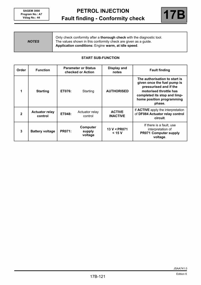
PETROL INJECTIONFault finding - Conformity check 17B
17B-121
SAGEM 3000Program No.: A7
Vdiag No.: 44
START SUB-FUNCTION
NOTESOnly check conformity after a thorough check with the diagnostic tool.The values shown in this conformity check are given as a guide. Application conditions: Engine warm, at idle speed.
Order FunctionParameter or Status checked or Action
Display and notes
Fault finding
1 Starting ET076: Starting AUTHORISED
The authorisation to start is given once the fuel pump is
pressurised and if the motorised throttle has
completed its stop and limp-home position programming
phase.
2Actuator relay
controlET048:
Actuator relay control
ACTIVEINACTIVE
If ACTIVE apply the interpretation of DF084 Actuator relay control
circuit.
3 Battery voltage PR071:Computer
supply voltage
13 V < PR071 < 15 V
If there is a fault, use interpretation of
PR071 Computer supply voltage.
JSAA741.0
Edition 6
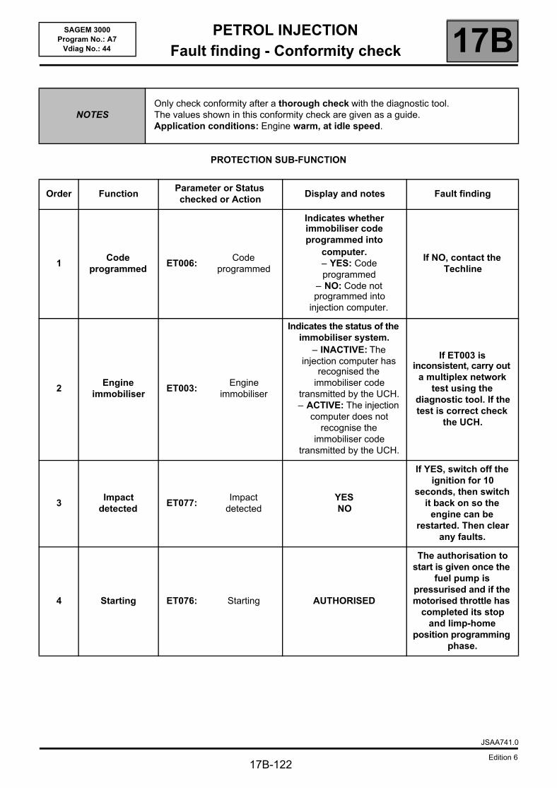
PETROL INJECTIONFault finding - Conformity check 17B
17B-122
SAGEM 3000Program No.: A7
Vdiag No.: 44
PROTECTION SUB-FUNCTION
NOTESOnly check conformity after a thorough check with the diagnostic tool.The values shown in this conformity check are given as a guide. Application conditions: Engine warm, at idle speed.
Order FunctionParameter or Status checked or Action
Display and notes Fault finding
1Code
programmedET006:
Code programmed
Indicates whether immobiliser code programmed into
computer.– YES: Code programmed
– NO: Code not programmed into
injection computer.
If NO, contact the Techline
2Engine
immobiliserET003:
Engine immobiliser
Indicates the status of the immobiliser system.
– INACTIVE: The injection computer has
recognised the immobiliser code
transmitted by the UCH.– ACTIVE: The injection
computer does not recognise the
immobiliser code transmitted by the UCH.
If ET003 is inconsistent, carry out
a multiplex network test using the
diagnostic tool. If the test is correct check
the UCH.
3Impact
detectedET077:
Impact detected
YESNO
If YES, switch off the ignition for 10
seconds, then switch it back on so the
engine can be restarted. Then clear
any faults.
4 Starting ET076: Starting AUTHORISED
The authorisation to start is given once the
fuel pump is pressurised and if the motorised throttle has
completed its stop and limp-home
position programming phase.
JSAA741.0
Edition 6
PETROL INJECTIONFault finding - Conformity check 17B
17B-123
SAGEM 3000Program No.: A7
Vdiag No.: 44
TORQUE MANAGEMENT SUB-FUNCTION
NOTESOnly check conformity after a thorough check with the diagnostic tool.The values shown in this conformity check are given as a guide. Application conditions: Engine warm, at idle speed.
Order FunctionParameter or Status checked
or ActionDisplay and notes Fault finding
1
Torque
PR100: Torque lapse 0 Nm
If there is a fault, test the multiplex
network; if the test is OK, check the
automatic transmission.
2 PR015: Engine torque- 50 Nm < PR015
< 200 Nm
3 PR123:Estimated driver demand engine
torque
0 Nm < PR123 < 200 Nm
4 PR122:
Torque received by automatic
transmission converter
0 Nm
5 PR124:Resistant engine
torque transmitted via multiplex line
0 Nm
JSAA741.0
Edition 6
PETROL INJECTIONFault finding - Status summary table 17B
17B-124
SAGEM 3000Program No.: A7
Vdiag No.: 44 Fault finding - Status summary table
Tool Status Diagnostic tool title
ET001 + After ignition computer feed
ET003 Engine immobiliser
ET004 Air conditioning authorisation
ET006 Code programmed
ET014 Fan unit 1 check
ET015 Fan unit 2 check
ET023 Fast idle speed request
ET032 Cruise control deactivation
ET039 Brake pedal
ET040 Clutch pedal
ET042 Cruise control/speed limiter
ET045 CC/SL selector switch on steering wheel
ET047 Fuel pump control circuit
ET048 Actuator relay control
ET050 Canister bleed control
ET051 Throttle stop programming
ET052 Upstream O2 sensor heating
ET053 Downstream O2 sensor heating
ET054 Idle speed regulation
ET055 Upstream sensor richness loop
ET056 Richness double loop
ET057 Misfiring on cylinder 1
ET058 Misfiring on cylinder 2
ET059 Misfiring on cylinder 3
ET060 Misfiring on cylinder 4
ET062 Flywheel signal
ET063 Park/Neutral position
JSAA741.0
Edition 6
PETROL INJECTIONFault finding - Status summary table 17B
17B-125
SAGEM 3000Program No.: A7
Vdiag No.: 44
Tool Status Diagnostic tool title
ET064 Level 1 injection fault
ET065 Level 2 Injection fault
ET074 OBD warning light illuminated by AT
ET075 Pedal released and throttle closed
ET076 Starting
ET077 Impact detected
ET079 Air conditioning present
ET081 Accelerator pedal position
ET082 Motorised throttle position
ET083 Camshaft dephaser in defect mode
ET084 Camshaft dephaser
ET086 Camshaft dephaser control
ET088 Compressor actuation request
ET089 Flywheel target programming
ET111 RCH number set
ET112 RCH cut-off
ET564 Type 1 defect mode
ET565 Type 2 defect mode
ET566 Type 3 defect mode
ET567 Type 4 defect mode
ET568 Type 5 defect mode
ET569 Type 6 defect mode
JSAA741.0
Edition 6
PETROL INJECTIONFault finding - Interpretation of statuses 17B
17B-126
SAGEM 3000Program No.: A7
Vdiag No.: 44 Fault finding - Interpretation of statuses
ET039
BRAKE PEDAL
NOTES There must be no present or stored faults.
Check the condition of the pedal assembly. Check the cleanliness and condition of the dual-contact brake switch and its connections. Repair if necessary.
With the ignition switched on, check for + 12 V on track 1 of the brake light switch. Repair if necessary.
Disconnect the battery and the injection computer.Check the cleanliness and condition of the connections.Using the Universal bornier, check the insulation and continuity of the following connection:
Injection computer, connector A, track E4 track 3 of the brake switchRepair if necessary.
If the fault is still present, replace the switch.
AFTER REPAIR Repeat the conformity check from the start.
JSAA741.0
Edition 6
PETROL INJECTIONFault finding - Interpretation of statuses 17B
17B-127
SAGEM 3000Program No.: A7
Vdiag No.: 44
ET040
CLUTCH PEDAL
NOTES There must be no present or stored faults.
Check that the pedal assembly is in good condition.Check the cleanliness and condition of the clutch pedal switch and its connections.Repair if necessary.
Check for earth on track 2 of the clutch pedal switch connector.Repair if necessary.
Disconnect the battery and the injection computer. Check the cleanliness and condition of the connections.Using the Universal bornier, check the insulation and continuity of the following connection:
Injection computer, connector A, track C4 track 1 of the clutch pedal switch Repair if necessary.
If the fault is still present, replace the switch.
AFTER REPAIR Repeat the conformity check from the start.
JSAA741.0
Edition 6
PETROL INJECTIONFault finding - Interpretation of statuses 17B
17B-128
SAGEM 3000Program No.: A7
Vdiag No.: 44
ET042
CRUISE-CONTROL/SPEED LIMITER
NOTES
There must be no present or stored faults.
IMPORTANTTo remove or check the Cruise control/speed limiter control switches you need to remove the airbag (See MR 364, Mechanics, 88C, Airbag and pretensioners).
With the ignition on, check for + 12 V on the cruise control/speed limiter selector switch (see Technical Note 8227, Wiring diagram, MEGANE II, 1081).Repair if necessary.
Disconnect the battery.Disconnect the computer. Check the cleanliness and condition of the connections.Using the universal bornier, check for insulation and continuity on the following connections:
Injection computer, connector A, track A2 track A3 of the cruise control or speed limiter on/off switch
Injection computer, connector A, track C3 track B1 of the cruise control or speed limiter on/off switch
Repair if necessary.
If the fault is still present, replace the switch.
AFTER REPAIR Repeat the conformity check from the start.
JSAA741.0
Edition 6
PETROL INJECTIONFault finding - Interpretation of statuses 17B
17B-129
SAGEM 3000Program No.: A7
Vdiag No.: 44
ET045
CRUISE CONTROL/SPEED LIMITER SELECTOR SWITCH ON STEERING WHEEL
NOTES
There must be no present or stored faults.
IMPORTANTTo remove or check the Cruise control/speed limiter control switches you need to remove the airbag (See MR 364, Mechanics, 88C, Airbag and pretensioners).
Check the cleanliness and condition of the incrementing switches at the steering wheel and their connections. Repair if necessary.
Check for earth on the incrementing switches at the steering wheel (see Technical Note 8227, Wiring Diagram, MEGANE II, 1081).Repair if necessary.
Disconnect the battery.Disconnect the computer. Check the cleanliness and condition of the connections.Using the universal bornier, check the insulation and continuity on the following connections:
Injection computer, connector A, track D2 track 2 of the steering wheel control switchInjection computer, connector A, track D3 track 1 of the steering wheel control switch
Repair if necessary.
If the fault is still present, replace the defective switch.
AFTER REPAIR Repeat the conformity check from the start.
JSAA741.0
Edition 6
PETROL INJECTIONFault finding - Interpretation of statuses 17B
17B-130
SAGEM 3000Program No.: A7
Vdiag No.: 44
ET052
UPSTREAM O2 SENSOR HEATING
NOTES There must be no present or stored faults.
Check the cleanliness and condition of the upstream oxygen sensor and its connections.Repair if necessary.
With the ignition on, check for + 12 V on track A of the upstream oxygen sensor connector.If + 12 V is not present:– disconnect the battery,– disconnect the connector marked PPM1 from the Protection and Switching Unit,– check the cleanliness and condition of the connections,– using the Universal bornier, check the continuity on the following connection:
Protection and Switching Unit PPM1 connector, track 2 track A of the upstream oxygen sensor
Reconnect the Protection and Switching Unit connector and reconnect the battery.With the ignition on, if there is still no + 12 V at the upstream oxygen sensor connector, there is a fault in the Protection and Switching Unit.Contact Techline.
Disconnect the battery and the injection computer.Check the cleanliness and condition of the connections.Using the universal bornier, check for insulation and continuity on the following connection:
Injection computer, connector C, track L2 track B of the upstream oxygen sensor
Repair if necessary.
Measure the heating resistance between tracks A and B of the upstream oxygen sensor. Replace the upstream oxygen sensor if the resistance is not approximately 9 ΩΩΩΩ at 20 °°°°C.
If the fault is still present, replace the upstream oxygen sensor.
AFTER REPAIR Repeat the conformity check from the start.
JSAA741.0
Edition 6
PETROL INJECTIONFault finding - Interpretation of statuses 17B
17B-131
SAGEM 3000Program No.: A7
Vdiag No.: 44
ET053
DOWNSTREAM O2 SENSOR HEATING
NOTES There must be no present or stored faults.
Check the cleanliness and condition of the downstream oxygen sensor and its connections. Repair if necessary.
Check for the + 12 V feed on track A, downstream oxygen sensor connector with the ignition on.If + 12 V is not present:– disconnect the battery,– disconnect the connector marked PPM1 in the Protection and Switching Unit,– check the cleanliness and condition of the connections,– using the Universal bornier, check for continuity on the following connection:
Protection and Switching Unit track 2 connector PPM1 track A of the downstream oxygen sensor
Reconnect the Protection and Switching Unit connector and reconnect the battery.With the ignition on, if the + 12 V is still not present on the downstream oxygen sensor connector, there is a fault in the Protection and Switching Unit.Contact Techline.
Disconnect the battery and the injection computer. Check the cleanliness and condition of the connections.Using the universal bornier, check for insulation and continuity on the following connection:
Injection computer, connector C, track L3 track B of the downstream oxygen sensor
Repair if necessary.
Measure the heating resistance between tracks A and B of the downstream oxygen sensor. Replace the downstream oxygen sensor if the resistance is not approximately 9 ΩΩΩΩ at 20 °°°°C.
If the fault is still present, replace the downstream oxygen sensor.
AFTER REPAIR Repeat the conformity check from the start.
JSAA741.0
Edition 6
PETROL INJECTIONFault finding - Interpretation of statuses 17B
17B-132
SAGEM 3000Program No.: A7
Vdiag No.: 44
ET054
IDLE SPEED REGULATION
NOTES
There must be no present or stored faults.
Check the parameters PR032, PR058, PR064, PR118, PR119 and PR030.Check that all these parameters are completely correct.
IDLE SPEED TOO LOW
Check:– the engine oil level (too high ⇒ splashing),– that the exhaust pipe is not blocked (catalytic converter damaged),– the cleanliness and conformity of the air filter,– that the air inlet circuit is not blocked,– that the throttle valve is not clogged,– the condition and conformity of the spark plugs,– the fuel circuit sealing,– the fuel pressure and flow (see MR 364 Mechanical, 17B, Petrol injection),– the condition and cleanliness of the injectors,– the cylinder compressions,– the timing adjustment,– the hydraulic tappets if there is camshaft noise (see MR 364 Mechanical, 11A, Top and front of engine).Repair the defective component if necessary.
JSAA741.0
Edition 6
PETROL INJECTIONFault finding - Interpretation of statuses 17B
17B-133
SAGEM 3000Program No.: A7
Vdiag No.: 44
ET054
CONTINUED
IDLE SPEED TOO HIGH
Check:– the engine oil level (too high ⇒ oil combustion),– that the restrictions are present in the oil vapour rebreathing circuit,– the sealing between the throttle valve and inlet manifold,– the manifold pressure sensor sealing,– the fuel vapour absorber bleed, which must not be jammed open,– the fuel vapour absorber bleed system sealing,– the brake servo system sealing,– the sealing between the inlet manifold and cylinder head,– the oil vapour recovery circuit sealing between the inlet manifold and cylinder head,– the fuel pressure and flow (see MR 364 Mechanical, 17B, Petrol injection),– the condition and cleanliness of the injectors,– the cylinder compressions,– the timing adjustment,– the hydraulic tappets if there is camshaft noise (see MR 364 Mechanical, 11A, Top and front of engine).Repair the defective component if necessary.
AFTER REPAIR Repeat the conformity check from the start.
JSAA741.0
Edition 6
PETROL INJECTIONFault finding - Interpretation of statuses 17B
17B-134
SAGEM 3000Program No.: A7
Vdiag No.: 44
ET055
UPSTREAM SENSOR RICHNESS LOOP
NOTES There must be no present or stored faults.
Check the cleanliness and condition of the upstream oxygen sensor connections.Repair if necessary.
With the ignition on, check for + 12 V on track A of the upstream oxygen sensor connector.If + 12 V is not present:– disconnect the battery,– disconnect the connector marked PPM1 in the Protection and Switching Unit,– check the cleanliness and condition of the connections,– using the Universal bornier, check for continuity on the following connection:
Protection and Switching Unit track 2 connector PPM1 track A of the upstream oxygen sensor
Reconnect the Protection and Switching Unit connector and reconnect the battery.With the ignition on, if there is still no + 12 V at the upstream oxygen sensor connector, there is a fault in the Protection and Switching Unit.Contact Techline.
Disconnect the battery and the injection computer.Check the cleanliness and condition of the connections.Using the universal bornier, check the insulation and continuity on the following connections:
Injection computer, connector C, track C1 track D of the upstream oxygen sensor
Injection computer, connector C, track B1 track C of the upstream oxygen sensor
Injection computer, connector C, track L2 track B of the upstream oxygen sensor
Repair if necessary.
Measure the heating resistance between tracks A and B of the upstream oxygen sensor.Replace the upstream oxygen sensor if the resistance is not approximately 9 ΩΩΩΩ at 20 °°°°C.
Check the condition and secure fitting of the upstream oxygen sensor.If the vehicle is driven frequently in town, carry out a decoking procedure.
JSAA741.0
Edition 6
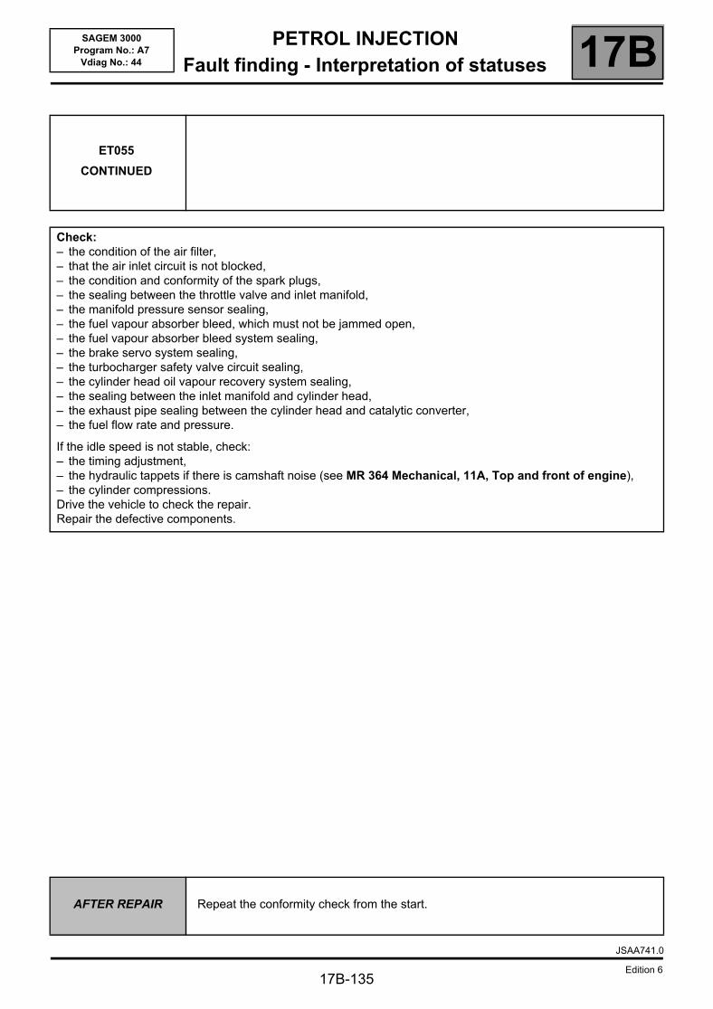
PETROL INJECTIONFault finding - Interpretation of statuses 17B
17B-135
SAGEM 3000Program No.: A7
Vdiag No.: 44
ET055
CONTINUED
Check:– the condition of the air filter,– that the air inlet circuit is not blocked,– the condition and conformity of the spark plugs,– the sealing between the throttle valve and inlet manifold,– the manifold pressure sensor sealing,– the fuel vapour absorber bleed, which must not be jammed open,– the fuel vapour absorber bleed system sealing,– the brake servo system sealing,– the turbocharger safety valve circuit sealing,– the cylinder head oil vapour recovery system sealing,– the sealing between the inlet manifold and cylinder head,– the exhaust pipe sealing between the cylinder head and catalytic converter,– the fuel flow rate and pressure.
If the idle speed is not stable, check:– the timing adjustment,– the hydraulic tappets if there is camshaft noise (see MR 364 Mechanical, 11A, Top and front of engine),– the cylinder compressions.Drive the vehicle to check the repair.Repair the defective components.
AFTER REPAIR Repeat the conformity check from the start.
JSAA741.0
Edition 6
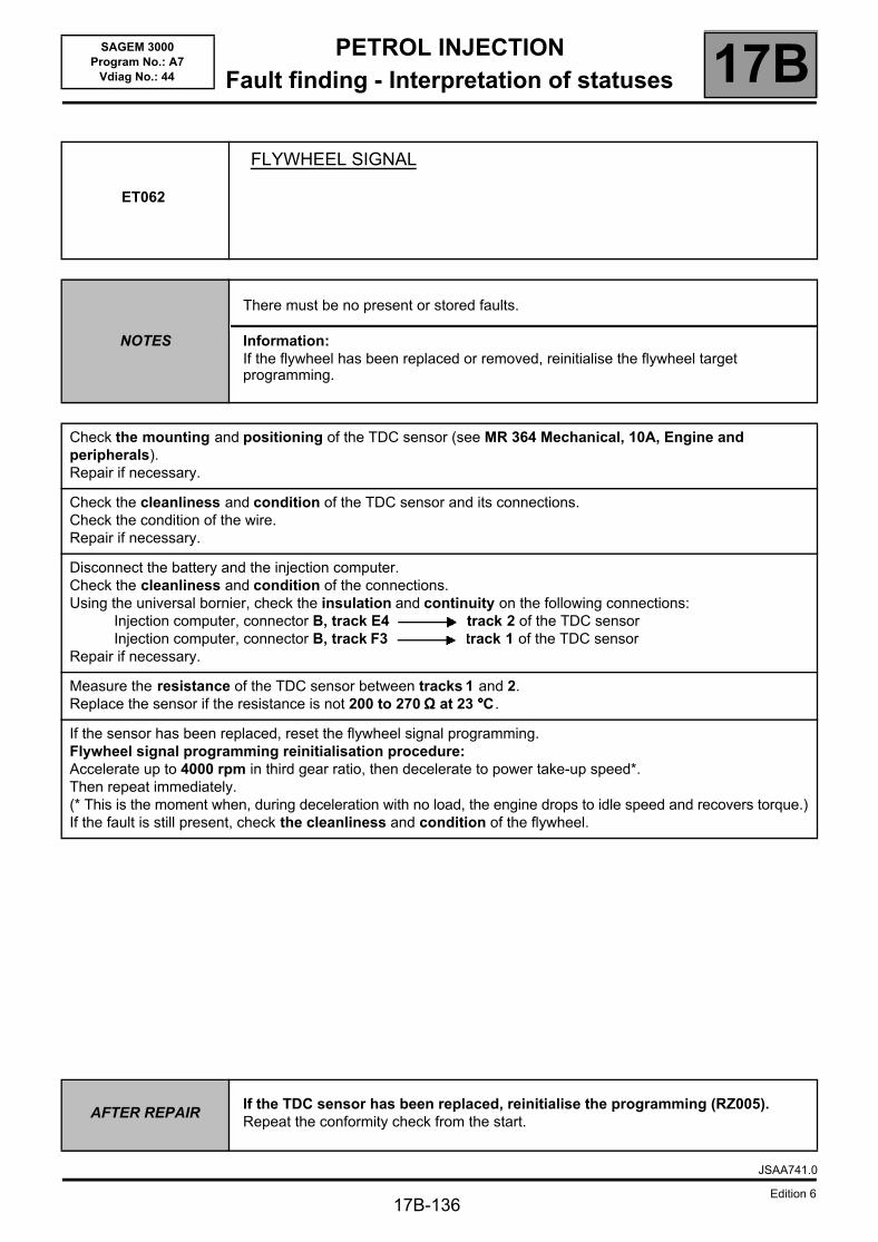
PETROL INJECTIONFault finding - Interpretation of statuses 17B
17B-136
SAGEM 3000Program No.: A7
Vdiag No.: 44
ET062
FLYWHEEL SIGNAL
NOTES
There must be no present or stored faults.
Information:If the flywheel has been replaced or removed, reinitialise the flywheel target programming.
Check the mounting and positioning of the TDC sensor (see MR 364 Mechanical, 10A, Engine and peripherals).Repair if necessary.
Check the cleanliness and condition of the TDC sensor and its connections.Check the condition of the wire.Repair if necessary.
Disconnect the battery and the injection computer.Check the cleanliness and condition of the connections.Using the universal bornier, check the insulation and continuity on the following connections:
Injection computer, connector B, track E4 track 2 of the TDC sensorInjection computer, connector B, track F3 track 1 of the TDC sensor
Repair if necessary.
Measure the resistance of the TDC sensor between tracks 1 and 2.Replace the sensor if the resistance is not 200 to 270 ΩΩΩΩ at 23 °°°°C.
If the sensor has been replaced, reset the flywheel signal programming.Flywheel signal programming reinitialisation procedure:Accelerate up to 4000 rpm in third gear ratio, then decelerate to power take-up speed*.Then repeat immediately.(* This is the moment when, during deceleration with no load, the engine drops to idle speed and recovers torque.)If the fault is still present, check the cleanliness and condition of the flywheel.
AFTER REPAIRIf the TDC sensor has been replaced, reinitialise the programming (RZ005).Repeat the conformity check from the start.
JSAA741.0
Edition 6
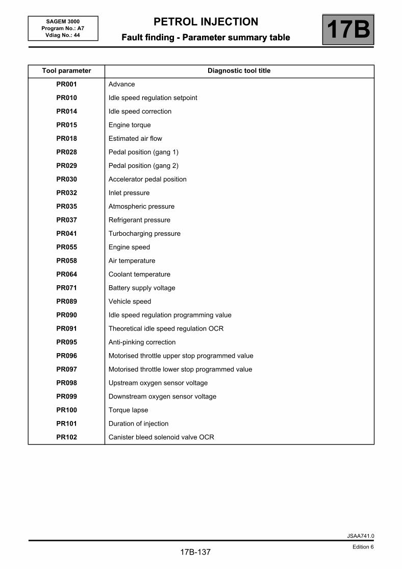
PETROL INJECTIONFault finding - Parameter summary table 17B
17B-137
SAGEM 3000Program No.: A7
Vdiag No.: 44 Fault finding - Parameter summary table
Tool parameter Diagnostic tool title
PR001 Advance
PR010 Idle speed regulation setpoint
PR014 Idle speed correction
PR015 Engine torque
PR018 Estimated air flow
PR028 Pedal position (gang 1)
PR029 Pedal position (gang 2)
PR030 Accelerator pedal position
PR032 Inlet pressure
PR035 Atmospheric pressure
PR037 Refrigerant pressure
PR041 Turbocharging pressure
PR055 Engine speed
PR058 Air temperature
PR064 Coolant temperature
PR071 Battery supply voltage
PR089 Vehicle speed
PR090 Idle speed regulation programming value
PR091 Theoretical idle speed regulation OCR
PR095 Anti-pinking correction
PR096 Motorised throttle upper stop programmed value
PR097 Motorised throttle lower stop programmed value
PR098 Upstream oxygen sensor voltage
PR099 Downstream oxygen sensor voltage
PR100 Torque lapse
PR101 Duration of injection
PR102 Canister bleed solenoid valve OCR
JSAA741.0
Edition 6
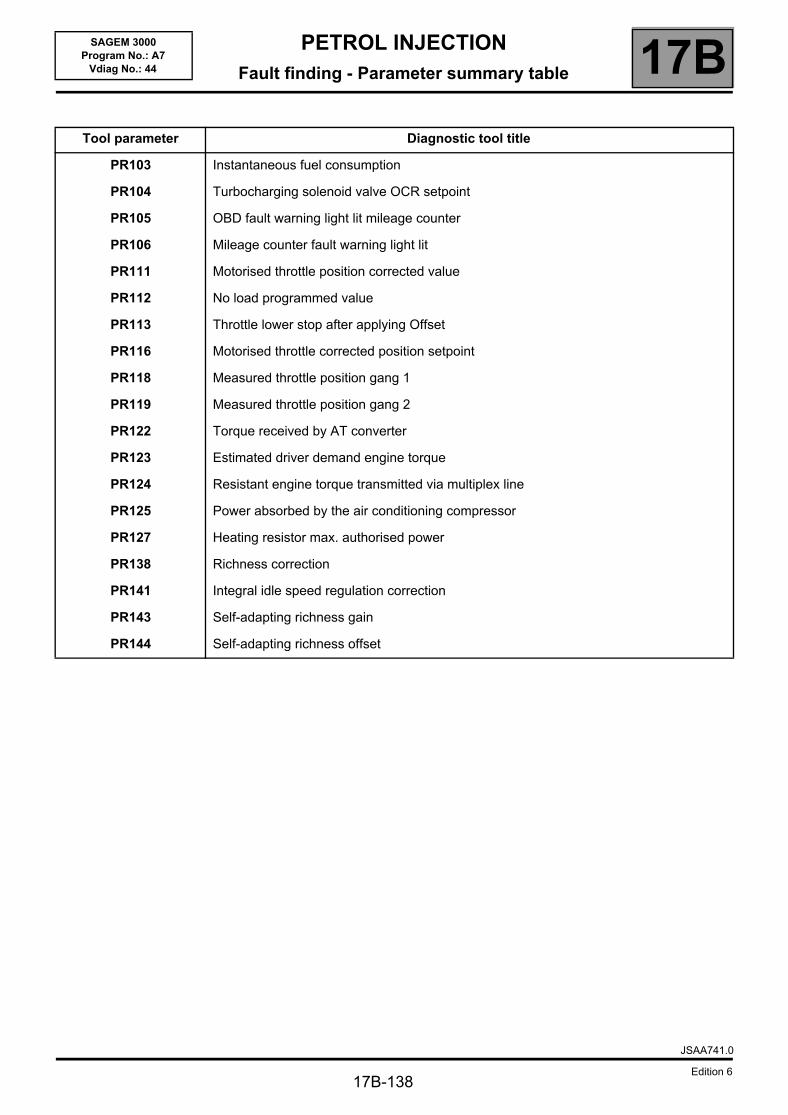
PETROL INJECTIONFault finding - Parameter summary table 17B
17B-138
SAGEM 3000Program No.: A7
Vdiag No.: 44
Tool parameter Diagnostic tool title
PR103 Instantaneous fuel consumption
PR104 Turbocharging solenoid valve OCR setpoint
PR105 OBD fault warning light lit mileage counter
PR106 Mileage counter fault warning light lit
PR111 Motorised throttle position corrected value
PR112 No load programmed value
PR113 Throttle lower stop after applying Offset
PR116 Motorised throttle corrected position setpoint
PR118 Measured throttle position gang 1
PR119 Measured throttle position gang 2
PR122 Torque received by AT converter
PR123 Estimated driver demand engine torque
PR124 Resistant engine torque transmitted via multiplex line
PR125 Power absorbed by the air conditioning compressor
PR127 Heating resistor max. authorised power
PR138 Richness correction
PR141 Integral idle speed regulation correction
PR143 Self-adapting richness gain
PR144 Self-adapting richness offset
JSAA741.0
Edition 6
PETROL INJECTIONFault finding - Interpretation of parameters 17B
17B-139
SAGEM 3000Program No.: A7
Vdiag No.: 44 Fault finding - Interpretation of parameters
PR030
ACCELERATOR PEDAL POSITION
NOTES There must be no present or stored faults.
Check that the pedal mechanism has not seized.Check the cleanliness and condition of the pedal potentiometer connections.Repair if necessary.
Disconnect the battery and the injection computer.Check the cleanliness and condition of the connections.Using the Universal bornier, check the insulation and continuity of the following connections:
Injection computer, connector A, track H3 track 5 of the pedal potentiometerInjection computer, connector A, track G2 track 3 of the pedal potentiometerInjection computer, connector A, track H2 track 4 of the pedal potentiometerInjection computer, connector A, track F4 track 6 of the pedal potentiometerInjection computer, connector A, track F2 track 2 of the pedal potentiometerInjection computer, connector A, track F3 track 1 of the pedal potentiometer
Repair if necessary.
If the fault is still present, replace the pedal potentiometer.
AFTER REPAIR Repeat the conformity check from the start.
JSAA741.0
Edition 6
PETROL INJECTIONFault finding - Interpretation of parameters 17B
17B-140
SAGEM 3000Program No.: A7
Vdiag No.: 44
PR032
INLET PRESSURE
NOTES There must be no present or stored faults.
Check the cleanliness and condition of the manifold pressure sensor and its connections. Repair if necessary.
Disconnect the battery and the injection computer.Check the cleanliness and condition of the connections.Using the Universal bornier, check the insulation and continuity of the following connections:
Computer, connector B, track H2 track 1 of the manifold pressure sensor.Computer, connector B, track H3 track 3 of the manifold pressure sensorComputer, connector B, track H4 track 2 of the manifold pressure sensor
Repair if necessary.
If the fault is still present, replace the manifold pressure sensor.
If the fault is still present, carry out the following checks:The inlet line must be perfectly sealed, from the throttle valve to the cylinder head.Check:– the condition of the air filter,– that the air inlet circuit is not blocked,– the sealing between the throttle valve and inlet manifold,– the manifold pressure sensor sealing,– the fuel vapour absorber bleed, which must not be jammed open,– the fuel vapour absorber bleed system sealing,– the brake servo system sealing,– the turbocharger safety valve circuit sealing,– the cylinder head oil vapour recovery system sealing,– the sealing between the inlet manifold and cylinder head,– the exhaust pipe sealing between the cylinder head and catalytic converter.Repair if necessary.
AFTER REPAIR Repeat the conformity check from the start.
JSAA741.0
Edition 6
PETROL INJECTIONFault finding - Interpretation of parameters 17B
17B-141
SAGEM 3000Program No.: A7
Vdiag No.: 44
PR037
REFRIGERANT PRESSURE
NOTES There must be no present or stored faults.
Check the cleanliness and condition of the refrigerant pressure sensor and its connections.Repair if necessary.
Disconnect the battery and the injection computer.Check the cleanliness and condition of the connections.Using the universal bornier, check the insulation and continuity on the following connections:
Injection computer, connector B, track J2 track B of the refrigerant pressure sensorInjection computer, connector B, track J3 track C of the refrigerant pressure sensorInjection computer, connector B, track K2 track A of the refrigerant pressure sensor
Repair if necessary.
If the fault is still present, replace the refrigerant sensor.If the fault is still present, check the air conditioning circuit (see MR 364 Mechanical, 62A, Air conditioning).
AFTER REPAIR Repeat the conformity check from the start.
JSAA741.0
Edition 6
PETROL INJECTIONFault finding - Interpretation of parameters 17B
17B-142
SAGEM 3000Program No.: A7
Vdiag No.: 44
PR074
BATTERY VOLTAGE
NOTESThere must be no present or stored faults.No electrical consumers.
Ignition on
At idle speed
If the voltage is at minimum:Check the battery and the charging circuit (see MR 364 Mechanical, 16A, Starting - Charging).If the voltage is at maximum:Check that the charging voltage is correct and that no electrical consumers are on (see 16A, Starting - Charging).
If the voltage is at minimum:Check the battery and the charging circuit (see MR 364 Mechanical, 16A, Starting - Charging).If the voltage is at maximum:Check that the charging voltage is correct and that no electrical consumers are on (see 16A, Starting - Charging).
AFTER REPAIR Repeat the conformity check from the start.
JSAA741.0
Edition 6
PETROL INJECTIONFault finding - Interpretation of parameters 17B
17B-143
SAGEM 3000Program No.: A7
Vdiag No.: 44
PR095
ANTI-PINKING CORRECTION
NOTES There must be no present or stored faults.
The pinking sensor must not supply a zero signal, proving that it is recording the mechanical vibrations of the engine.
Check that there is the correct fuel in the fuel tank.Repair if necessary.
Check the condition and conformity of the spark plugs.Repair if necessary.
Check the tightness of the pinking sensor.Repair if necessary.
Check the cleanliness and the condition of the pinking sensor connections.Repair if necessary.
Disconnect the battery and the injection computer.Check the cleanliness and condition of the connections.Using the universal bornier, check the insulation and continuity on the following connections:
Injection computer, connector B, track B3 track 2 of the pinking sensorInjection computer, connector B, track B4 track 2 of the pinking sensorInjection computer, connector B, track B2 Shielding of the pinking sensor
Repair if necessary.
If the fault is still present, replace the pinking sensor.
AFTER REPAIR Repeat the conformity check from the start.
JSAA741.0
Edition 6
PETROL INJECTIONFault finding - Interpretation of parameters 17B
17B-144
SAGEM 3000Program No.: A7
Vdiag No.: 44
PR098
UPSTREAM OXYGEN SENSOR VOLTAGE
NOTES There must be no present or stored faults.
Check the cleanliness and condition of the upstream oxygen sensor connections.Repair if necessary.
Disconnect the battery and the injection computer.Check the cleanliness and condition of the connections.Using the universal bornier, check the insulation and continuity on the following connections:
Injection computer, connector C, track C1 track D of the upstream oxygen sensorInjection computer, connector C, track B1 track C of the upstream oxygen sensor
Repair if necessary.
Check that the upstream oxygen sensor is secure.Repair if necessary.
If the vehicle is driven frequently in town, carry out a decoking procedure.
Check that there are no leaks in the exhaust system, from the manifold to the catalytic converter.Repair if necessary.
If the fault is still present, replace the upstream oxygen sensor.If the fault has still not been cured, continue with the checks.Check:– the condition of the air filter,– that the air inlet circuit is not blocked,– the condition and conformity of the spark plugs,– that the catalytic converter is not clogged,– the sealing between the throttle valve and inlet manifold,– the manifold pressure sensor sealing,– the fuel vapour absorber bleed, which must not be jammed open,– the fuel vapour absorber bleed system sealing,– the brake servo system sealing,– the cylinder head oil vapour recovery system sealing,– the sealing between the inlet manifold and cylinder head,– the exhaust pipe sealing between the cylinder head and catalytic converter,– the fuel flow rate and pressure.
JSAA741.0
Edition 6
PETROL INJECTIONFault finding - Interpretation of parameters 17B
17B-145
SAGEM 3000Program No.: A7
Vdiag No.: 44
PR098
CONTINUED
If the idle speed is not stable, check:– the timing adjustment,– the hydraulic tappets if there is camshaft noise (see MR 364 Mechanical, 11A, Top and front of engine),– cylinder compression.Drive the vehicle to check the repair.
AFTER REPAIR Repeat the conformity check from the start.
JSAA741.0
Edition 6
PETROL INJECTIONFault finding - Interpretation of parameters 17B
17B-146
SAGEM 3000Program No.: A7
Vdiag No.: 44
PR099
DOWNSTREAM OXYGEN SENSOR VOLTAGE
NOTES There must be no present or stored faults.
Check the cleanliness and condition of the downstream oxygen sensor connections.Repair if necessary.
Disconnect the battery and the injection computer.Using the universal bornier, check the insulation and continuity on the following connections:
Injection computer, connector C, track A2 track D of the downstream oxygen sensorInjection computer, connector C, track B2 track C of the downstream oxygen sensor
Repair if necessary.
Check that the downstream oxygen sensor is secure.Repair if necessary.
If the vehicle is driven frequently in town, carry out the unclogging procedure (oxygen sensors and catalytic converter clogging).
Check that the exhaust pipe is completely leak free.Repair if necessary.
Replace the downstream oxygen sensor.
If the fault is still present, the catalytic converter is certainly damaged.
If the catalytic converter is defective, determine the cause of the destruction, otherwise the new catalytic converter may be damaged in turn.
Remove the catalytic converter.
Possible reasons for the destruction of a catalytic converter:– deformation (impact),– thermal shock (cold water splashed onto a hot catalytic converter can damage it),– defective injector or ignition: the catalytic converter is damaged by contact with fuel (coil fault, coil control fault,
injector jammed open),– injector leak,– abnormal oil or coolant consumption (defective cylinder head gasket),– use of a fuel additive or other equivalent product (obtain information from the customer because this type of
product can contaminate the catalytic converter and render it useless sooner or later).
Look up the service history of the vehicle or, if this is not possible, ask the customer if the vehicle has had injection or ignition faults.
If the cause of the catalytic converter damage has been found and the fault has disappeared, replace the catalytic converter.
AFTER REPAIR Repeat the conformity check from the start.
JSAA741.0
Edition 6
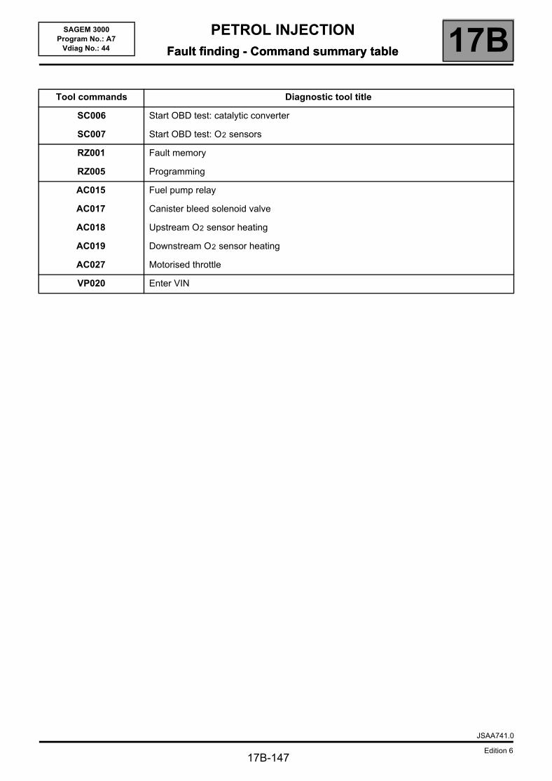
PETROL INJECTIONFault finding - Command summary table 17B
17B-147
SAGEM 3000Program No.: A7
Vdiag No.: 44 Fault finding - Command summary table
Tool commands Diagnostic tool title
SC006 Start OBD test: catalytic converter
SC007 Start OBD test: O2 sensors
RZ001 Fault memory
RZ005 Programming
AC015 Fuel pump relay
AC017 Canister bleed solenoid valve
AC018 Upstream O2 sensor heating
AC019 Downstream O2 sensor heating
AC027 Motorised throttle
VP020 Enter VIN
JSAA741.0
Edition 6
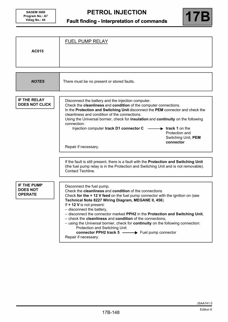
PETROL INJECTIONFault finding - Interpretation of commands 17B
17B-148
SAGEM 3000Program No.: A7
Vdiag No.: 44 Fault finding - Interpretation of commands
AC015
FUEL PUMP RELAY
NOTES There must be no present or stored faults.
IF THE RELAY DOES NOT CLICK
IF THE PUMP DOES NOT OPERATE
Disconnect the battery and the injection computer.Check the cleanliness and condition of the computer connections. In the Protection and Switching Unit disconnect the PEM connector and check the cleanliness and condition of the connections.Using the Universal bornier, check for insulation and continuity on the following connection:
Injection computer track D1 connector C track 1 on the Protection and Switching Unit, PEM connector
Repair if necessary.
If the fault is still present, there is a fault with the Protection and Switching Unit (the fuel pump relay is in the Protection and Switching Unit and is not removable).Contact Techline.
Disconnect the fuel pump.Check the cleanliness and condition of the connections.Check for the + 12 V feed on the fuel pump connector with the ignition on (see Technical Note 8227 Wiring Diagram, MEGANE II, 456).If + 12 V is not present:– disconnect the battery,– disconnect the connector marked PPH2 in the Protection and Switching Unit,– check the cleanliness and condition of the connections,– using the Universal bornier, check for continuity on the following connection:
Protection and Switching Unit connector PPH2 track 5 Fuel pump connector
Repair if necessary.
JSAA741.0
Edition 6
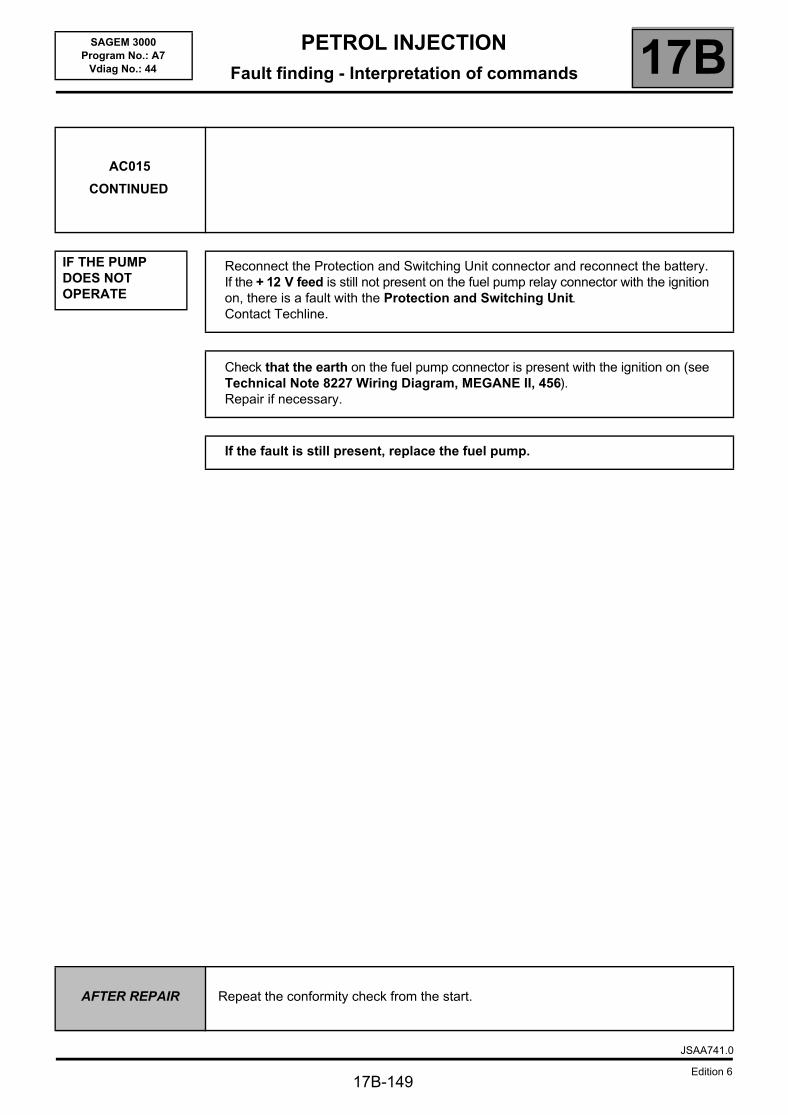
PETROL INJECTIONFault finding - Interpretation of commands 17B
17B-149
SAGEM 3000Program No.: A7
Vdiag No.: 44
AC015
CONTINUED
IF THE PUMP DOES NOT OPERATE
Reconnect the Protection and Switching Unit connector and reconnect the battery.If the + 12 V feed is still not present on the fuel pump relay connector with the ignition on, there is a fault with the Protection and Switching Unit.Contact Techline.
Check that the earth on the fuel pump connector is present with the ignition on (see Technical Note 8227 Wiring Diagram, MEGANE II, 456).Repair if necessary.
If the fault is still present, replace the fuel pump.
AFTER REPAIR Repeat the conformity check from the start.
JSAA741.0
Edition 6
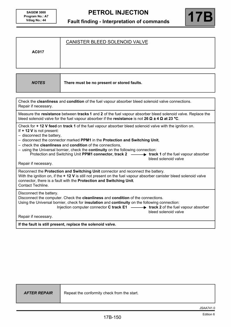
PETROL INJECTIONFault finding - Interpretation of commands 17B
17B-150
SAGEM 3000Program No.: A7
Vdiag No.: 44
AC017
CANISTER BLEED SOLENOID VALVE
NOTES There must be no present or stored faults.
Check the cleanliness and condition of the fuel vapour absorber bleed solenoid valve connections.Repair if necessary.
Measure the resistance between tracks 1 and 2 of the fuel vapour absorber bleed solenoid valve. Replace the bleed solenoid valve for the fuel vapour absorber if the resistance is not 26 ΩΩΩΩ ±±±± 4 ΩΩΩΩ at 23 °°°°C.
Check for + 12 V feed on track 1 of the fuel vapour absorber bleed solenoid valve with the ignition on.If + 12 V is not present:– disconnect the battery,– disconnect the connector marked PPM1 in the Protection and Switching Unit,– check the cleanliness and condition of the connections,– using the Universal bornier, check the continuity on the following connection:
Protection and Switching Unit PPM1 connector, track 2 track 1 of the fuel vapour absorber bleed solenoid valve
Repair if necessary.
Reconnect the Protection and Switching Unit connector and reconnect the battery.With the ignition on, if the + 12 V is still not present on the fuel vapour absorber canister bleed solenoid valve connector, there is a fault with the Protection and Switching Unit.Contact Techline.
Disconnect the battery.Disconnect the computer. Check the cleanliness and condition of the connections.Using the Universal bornier, check for insulation and continuity on the following connection:
Injection computer connector C track E1 track 2 of the fuel vapour absorber bleed solenoid valve
Repair if necessary.
If the fault is still present, replace the solenoid valve.
AFTER REPAIR Repeat the conformity check from the start.
JSAA741.0
Edition 6
PETROL INJECTIONFault finding - Interpretation of commands 17B
17B-151
SAGEM 3000Program No.: A7
Vdiag No.: 44
AC027
MOTORISED THROTTLE
WARNINGNever drive the vehicle without ensuring that there are no throttle valve faults.
NOTES There must be no present or stored faults.
Switch on the ignition and activate command AC027.If the motorised throttle does not work, apply the interpretation for DF079 Motorised throttle valve automatic control.
AFTER REPAIRIf the throttle valve has been replaced, reinitialise the programming (RZ005).Repeat the conformity check from the start.
JSAA741.0
Edition 6
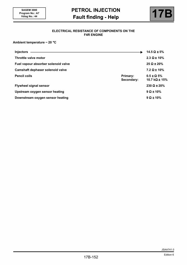
PETROL INJECTIONFault finding - Help 17B
17B-152
SAGEM 3000Program No.: A7
Vdiag No.: 44 Fault finding - Help
ELECTRICAL RESISTANCE OF COMPONENTS ON THEF4R ENGINE
Ambient temperature ~ 20 °°°°C
Injectors 14.5 ΩΩΩΩ ±±±± 5%
Throttle valve motor 2.3 ΩΩΩΩ ±±±± 10%
Fuel vapour absorber solenoid valve 25 ΩΩΩΩ ±±±± 20%
Camshaft dephaser solenoid valve 7.2 ΩΩΩΩ ±±±± 10%
Pencil coils Primary: Secondary:
0.5 ±±±± ΩΩΩΩ 5%10.7 kΩΩΩΩ ±±±± 15%
Flywheel signal sensor 230 ΩΩΩΩ ±±±± 20%
Upstream oxygen sensor heating 9 ΩΩΩΩ ±±±± 10%
Downstream oxygen sensor heating 9 ΩΩΩΩ ±±±± 10%
JSAA741.0
Edition 6
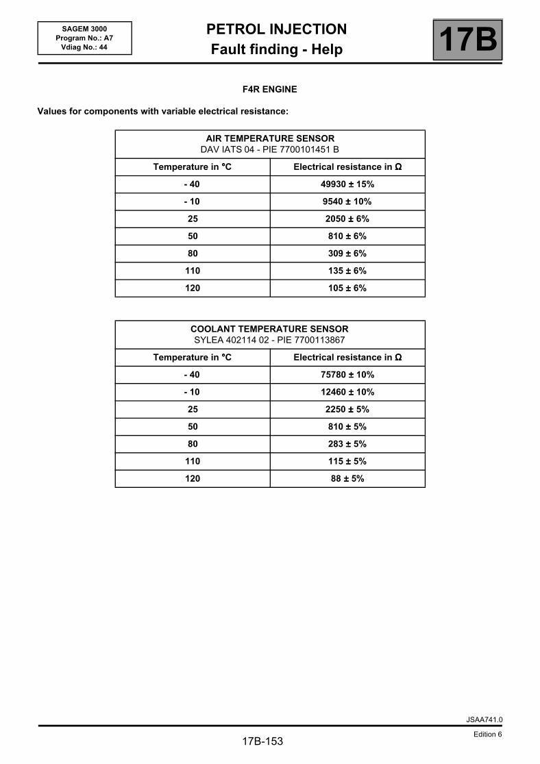
PETROL INJECTIONFault finding - Help 17B
17B-153
SAGEM 3000Program No.: A7
Vdiag No.: 44
F4R ENGINE
Values for components with variable electrical resistance:
AIR TEMPERATURE SENSORDAV IATS 04 - PIE 7700101451 B
Temperature in °°°°C Electrical resistance in ΩΩΩΩ
- 40 49930 ±±±± 15%
- 10 9540 ±±±± 10%
25 2050 ±±±± 6%
50 810 ±±±± 6%
80 309 ±±±± 6%
110 135 ±±±± 6%
120 105 ±±±± 6%
COOLANT TEMPERATURE SENSORSYLEA 402114 02 - PIE 7700113867
Temperature in °°°°C Electrical resistance in ΩΩΩΩ
- 40 75780 ±±±± 10%
- 10 12460 ±±±± 10%
25 2250 ±±±± 5%
50 810 ±±±± 5%
80 283 ±±±± 5%
110 115 ±±±± 5%
120 88 ±±±± 5%
JSAA741.0
Edition 6
PETROL INJECTIONFault finding - Customer complaints 17B
17B-154
SAGEM 3000Program No.: A7
Vdiag No.: 44 Fault finding - Customer complaints
NOTES
Only consult the customer complaints after performing a complete check with the diagnostic tool.WARNINGNever drive the vehicle without checking first that there are no throttle valve faults.
NO DIALOGUE WITH THE COMPUTER ALP 1
THE ENGINE WILL NOT START ALP 2
IDLING SPEED FAULTS ALP 3
FAULTS WHILE DRIVING ALP 4
AFTER REPAIR Repeat the conformity check from the start.
JSAA741.0
Edition 6
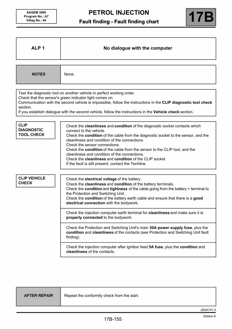
PETROL INJECTIONFault finding - Fault finding chart 17B
17B-155
SAGEM 3000Program No.: A7
Vdiag No.: 44 Fault finding - Fault finding chart
ALP 1 No dialogue with the computer
NOTES None.
Test the diagnostic tool on another vehicle in perfect working order.Check that the sensor's green indicator light comes on.Communication with the second vehicle is impossible, follow the instructions in the CLIP diagnostic tool check section.If you establish dialogue with the second vehicle, follow the instructions in the Vehicle check section.
CLIP DIAGNOSTIC TOOL CHECK
CLIP VEHICLE CHECK
Check the cleanliness and condition of the diagnostic socket contacts which connect to the vehicle.Check the condition of the cable from the diagnostic socket to the sensor, and the cleanliness and condition of the connections.Check the sensor connections.Check the condition of the cable from the sensor to the CLIP tool, and the cleanliness and condition of the connections.Check the cleanliness and condition of the CLIP socket.If the fault is still present, contact the Techline.
Check the electrical voltage of the battery.Check the cleanliness and condition of the battery terminals.Check the condition and tightness of the cable going from the battery + terminal to the Protection and Switching Unit.Check the condition of the battery earth cable and ensure that there is a good electrical connection with the bodywork.
Check the injection computer earth terminal for cleanliness and make sure it is properly connected to the bodywork.
Check the Protection and Switching Unit's main 30A power supply fuse, plus the condition and cleanliness of the contacts (see Protection and Switching Unit fault finding).
Check the injection computer after ignition feed 5A fuse, plus the condition and cleanliness of the contacts.
AFTER REPAIR Repeat the conformity check from the start.
JSAA741.0
Edition 6
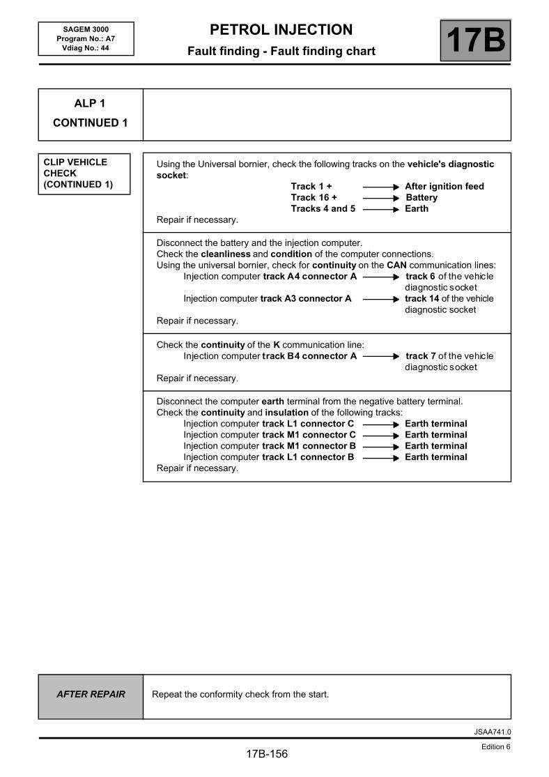
PETROL INJECTIONFault finding - Fault finding chart 17B
17B-156
SAGEM 3000Program No.: A7
Vdiag No.: 44
ALP 1
CONTINUED 1
CLIP VEHICLE CHECK (CONTINUED 1)
Using the Universal bornier, check the following tracks on the vehicle's diagnostic socket:
Track 1 + After ignition feedTrack 16 + BatteryTracks 4 and 5 Earth
Repair if necessary.
Disconnect the battery and the injection computer.Check the cleanliness and condition of the computer connections.Using the universal bornier, check for continuity on the CAN communication lines:
Injection computer track A4 connector A track 6 of the vehic lediagnostic socket
Injection computer track A3 connector A track 14 of the vehicle diagnostic socket
Repair if necessary.
Check the continuity of the K communication line:Injection computer track B4 connector A track 7 of the vehic le
diagnostic socketRepair if necessary.
Disconnect the computer earth terminal from the negative battery terminal.Check the continuity and insulation of the following tracks:
Injection computer track L1 connector C Earth terminalInjection computer track M1 connector C Earth terminalInjection computer track M1 connector B Earth terminalInjection computer track L1 connector B Earth terminal
Repair if necessary.
AFTER REPAIR Repeat the conformity check from the start.
JSAA741.0
Edition 6
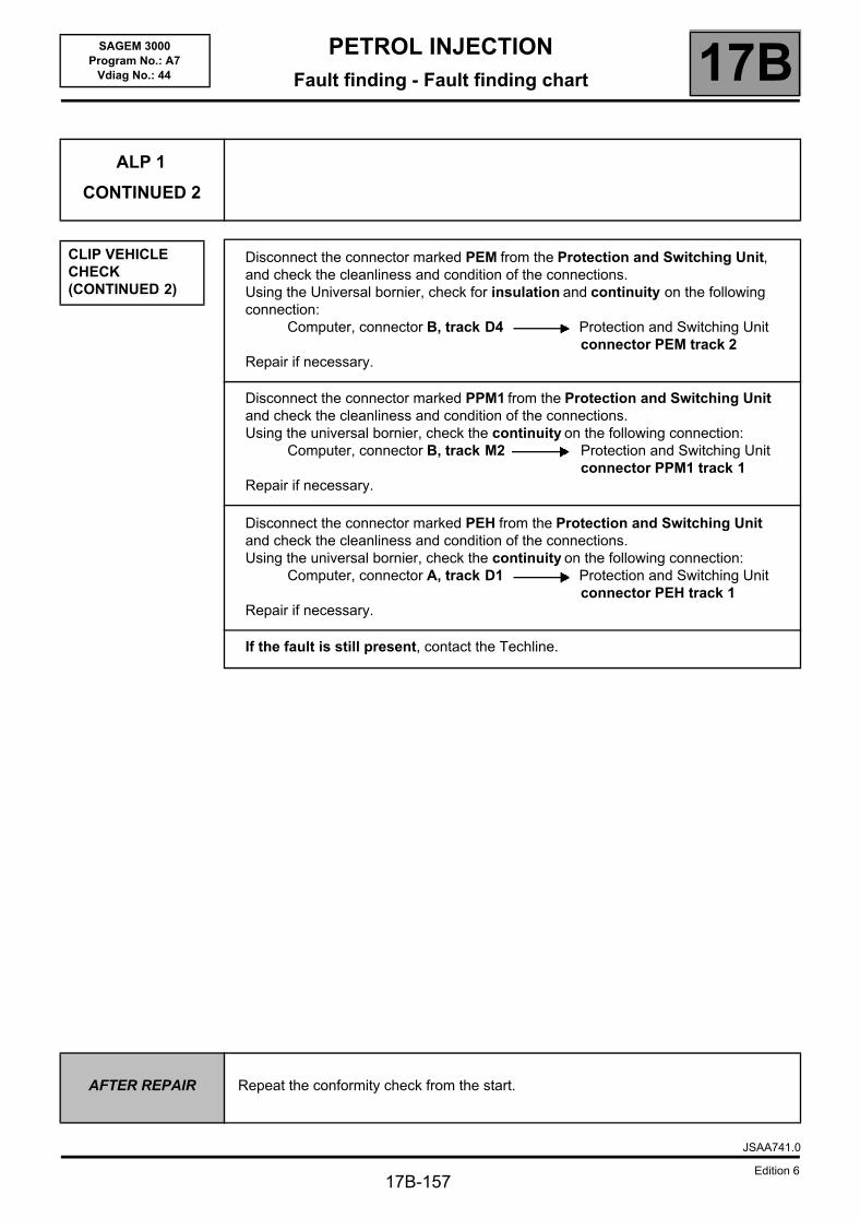
PETROL INJECTIONFault finding - Fault finding chart 17B
17B-157
SAGEM 3000Program No.: A7
Vdiag No.: 44
ALP 1
CONTINUED 2
CLIP VEHICLE CHECK (CONTINUED 2)
Disconnect the connector marked PEM from the Protection and Switching Unit, and check the cleanliness and condition of the connections.Using the Universal bornier, check for insulation and continuity on the following connection:
Computer, connector B, track D4 Protection and Switching Unit connector PEM track 2
Repair if necessary.
Disconnect the connector marked PPM1 from the Protection and Switching Unit and check the cleanliness and condition of the connections.Using the universal bornier, check the continuity on the following connection:
Computer, connector B, track M2 Protection and Switching Unit connector PPM1 track 1
Repair if necessary.
Disconnect the connector marked PEH from the Protection and Switching Unit and check the cleanliness and condition of the connections.Using the universal bornier, check the continuity on the following connection:
Computer, connector A, track D1 Protection and Switching Unit connector PEH track 1
Repair if necessary.
If the fault is still present, contact the Techline.
AFTER REPAIR Repeat the conformity check from the start.
JSAA741.0
Edition 6
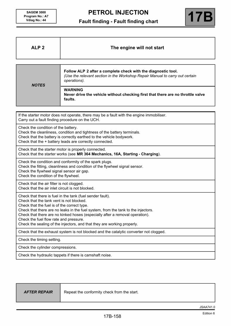
PETROL INJECTIONFault finding - Fault finding chart 17B
17B-158
SAGEM 3000Program No.: A7
Vdiag No.: 44
ALP 2 The engine will not start
NOTES
Follow ALP 2 after a complete check with the diagnostic tool.(Use the relevant section in the Workshop Repair Manual to carry out certain operations).
WARNINGNever drive the vehicle without checking first that there are no throttle valve faults.
If the starter motor does not operate, there may be a fault with the engine immobiliser.Carry out a fault finding procedure on the UCH.
Check the condition of the battery.Check the cleanliness, condition and tightness of the battery terminals.Check that the battery is correctly earthed to the vehicle bodywork.Check that the + battery leads are correctly connected.
Check that the starter motor is properly connected.Check that the starter works (see MR 364 Mechanics, 16A, Starting - Charging).
Check the condition and conformity of the spark plugs.Check the fitting, cleanliness and condition of the flywheel signal sensor.Check the flywheel signal sensor air gap.Check the condition of the flywheel.
Check that the air filter is not clogged.Check that the air inlet circuit is not blocked.
Check that there is fuel in the tank (fuel sender fault).Check that the tank vent is not blocked.Check that the fuel is of the correct type.Check that there are no leaks in the fuel system, from the tank to the injectors.Check that there are no kinked hoses (especially after a removal operation).Check the fuel flow rate and pressure.Check the sealing of the injectors, and that they are working properly.
Check that the exhaust system is not blocked and the catalytic converter not clogged.
Check the timing setting.
Check the cylinder compressions.
Check the hydraulic tappets if there is camshaft noise.
AFTER REPAIR Repeat the conformity check from the start.
JSAA741.0
Edition 6
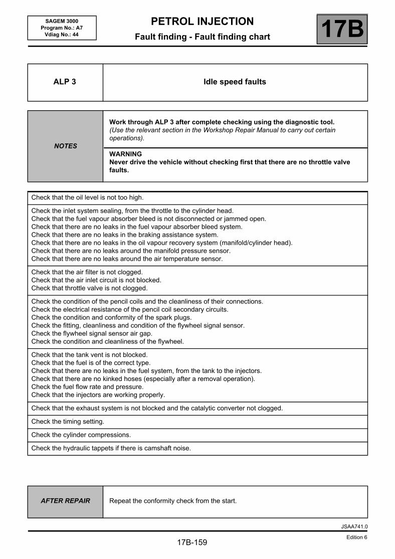
PETROL INJECTIONFault finding - Fault finding chart 17B
17B-159
SAGEM 3000Program No.: A7
Vdiag No.: 44
ALP 3 Idle speed faults
NOTES
Work through ALP 3 after complete checking using the diagnostic tool.(Use the relevant section in the Workshop Repair Manual to carry out certain operations).
WARNINGNever drive the vehicle without checking first that there are no throttle valve faults.
Check that the oil level is not too high.
Check the inlet system sealing, from the throttle to the cylinder head.Check that the fuel vapour absorber bleed is not disconnected or jammed open.Check that there are no leaks in the fuel vapour absorber bleed system.Check that there are no leaks in the braking assistance system.Check that there are no leaks in the oil vapour recovery system (manifold/cylinder head).Check that there are no leaks around the manifold pressure sensor.Check that there are no leaks around the air temperature sensor.
Check that the air filter is not clogged.Check that the air inlet circuit is not blocked.Check that throttle valve is not clogged.
Check the condition of the pencil coils and the cleanliness of their connections.Check the electrical resistance of the pencil coil secondary circuits.Check the condition and conformity of the spark plugs.Check the fitting, cleanliness and condition of the flywheel signal sensor.Check the flywheel signal sensor air gap.Check the condition and cleanliness of the flywheel.
Check that the tank vent is not blocked.Check that the fuel is of the correct type.Check that there are no leaks in the fuel system, from the tank to the injectors.Check that there are no kinked hoses (especially after a removal operation).Check the fuel flow rate and pressure.Check that the injectors are working properly.
Check that the exhaust system is not blocked and the catalytic converter not clogged.
Check the timing setting.
Check the cylinder compressions.
Check the hydraulic tappets if there is camshaft noise.
AFTER REPAIR Repeat the conformity check from the start.
JSAA741.0
Edition 6
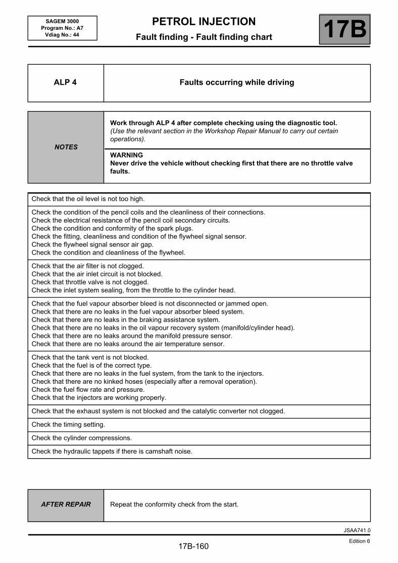
PETROL INJECTIONFault finding - Fault finding chart 17B
17B-160
SAGEM 3000Program No.: A7
Vdiag No.: 44
ALP 4 Faults occurring while driving
NOTES
Work through ALP 4 after complete checking using the diagnostic tool.(Use the relevant section in the Workshop Repair Manual to carry out certain operations).
WARNINGNever drive the vehicle without checking first that there are no throttle valve faults.
Check that the oil level is not too high.
Check the condition of the pencil coils and the cleanliness of their connections.Check the electrical resistance of the pencil coil secondary circuits.Check the condition and conformity of the spark plugs.Check the fitting, cleanliness and condition of the flywheel signal sensor.Check the flywheel signal sensor air gap.Check the condition and cleanliness of the flywheel.
Check that the air filter is not clogged.Check that the air inlet circuit is not blocked.Check that throttle valve is not clogged.Check the inlet system sealing, from the throttle to the cylinder head.
Check that the fuel vapour absorber bleed is not disconnected or jammed open.Check that there are no leaks in the fuel vapour absorber bleed system.Check that there are no leaks in the braking assistance system.Check that there are no leaks in the oil vapour recovery system (manifold/cylinder head).Check that there are no leaks around the manifold pressure sensor.Check that there are no leaks around the air temperature sensor.
Check that the tank vent is not blocked.Check that the fuel is of the correct type.Check that there are no leaks in the fuel system, from the tank to the injectors.Check that there are no kinked hoses (especially after a removal operation).Check the fuel flow rate and pressure.Check that the injectors are working properly.
Check that the exhaust system is not blocked and the catalytic converter not clogged.
Check the timing setting.
Check the cylinder compressions.
Check the hydraulic tappets if there is camshaft noise.
AFTER REPAIR Repeat the conformity check from the start.
JSAA741.0
Edition 6