Embed Size (px)
Citation preview
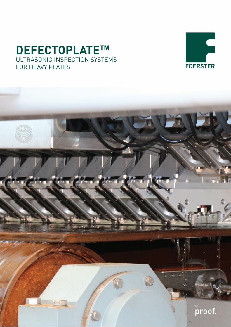
DEFECTOPLATETMULTRASONIC INSPECTION SYSTEMS FOR HEAVY PLATES
2 ULTRASONIC INSPECTION SYSTEMS
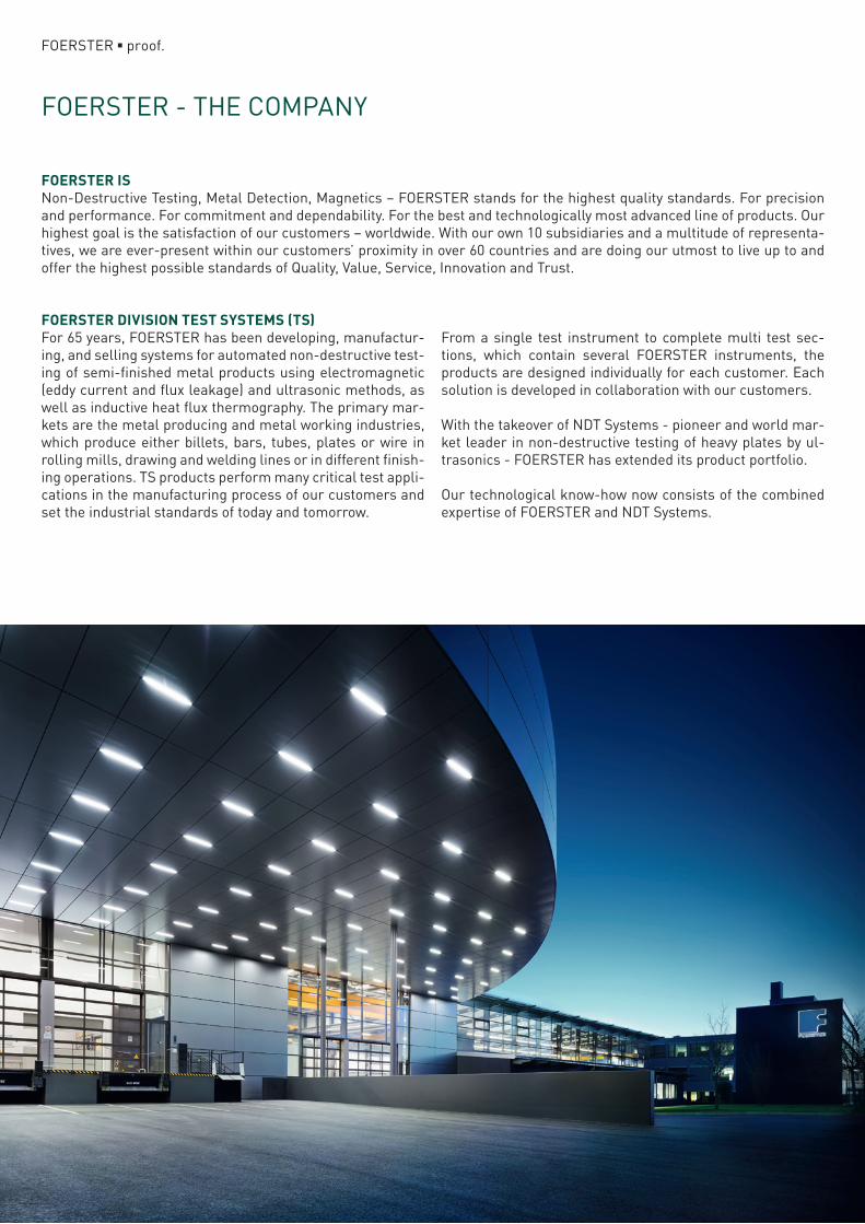
FOERSTER - THE COMPANY
FOERSTER ■ proof.
FOERSTER ISNon-Destructive Testing, Metal Detection, Magnetics – FOERSTER stands for the highest quality standards. For precision and performance. For commitment and dependability. For the best and technologically most advanced line of products. Our highest goal is the satisfaction of our customers – worldwide. With our own 10 subsidiaries and a multitude of representa-tives, we are ever-present within our customers’ proximity in over 60 countries and are doing our utmost to live up to and offer the highest possible standards of Quality, Value, Service, Innovation and Trust.
FOERSTER DIVISION TEST SYSTEMS (TS)For 65 years, FOERSTER has been developing, manufactur-ing, and selling systems for automated non-destructive test-ing of semi-finished metal products using electromagnetic (eddy current and flux leakage) and ultrasonic methods, as well as inductive heat flux thermography. The primary mar-kets are the metal producing and metal working industries, which produce either billets, bars, tubes, plates or wire in rolling mills, drawing and welding lines or in different finish-ing operations. TS products perform many critical test appli-cations in the manufacturing process of our customers and set the industrial standards of today and tomorrow.
From a single test instrument to complete multi test sec-tions, which contain several FOERSTER instruments, the products are designed individually for each customer. Each solution is developed in collaboration with our customers.
With the takeover of NDT Systems - pioneer and world mar-ket leader in non-destructive testing of heavy plates by ul-trasonics - FOERSTER has extended its product portfolio.
Our technological know-how now consists of the combined expertise of FOERSTER and NDT Systems.
3ULTRASONIC INSPECTION SYSTEMS
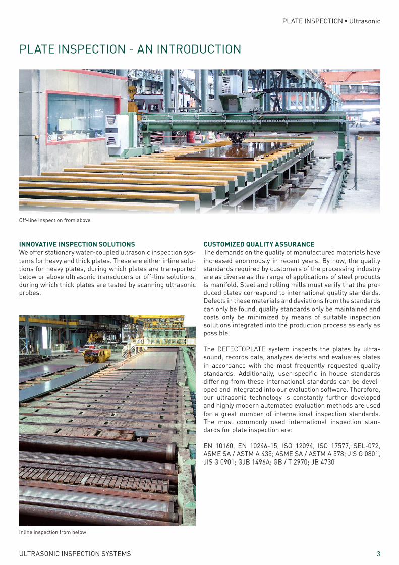
INNOVATIVE INSPECTION SOLUTIONSWe offer stationary water-coupled ultrasonic inspection sys-tems for heavy and thick plates. These are either inline solu-tions for heavy plates, during which plates are transported below or above ultrasonic transducers or off-line solutions, during which thick plates are tested by scanning ultrasonic probes.
PLATE INSPECTION - AN INTRODUCTION
CUSTOMIZED QUALITY ASSURANCEThe demands on the quality of manufactured materials have increased enormously in recent years. By now, the quality standards required by customers of the processing industry are as diverse as the range of applications of steel products is manifold. Steel and rolling mills must verify that the pro-duced plates correspond to international quality standards. Defects in these materials and deviations from the standards can only be found, quality standards only be maintained and costs only be minimized by means of suitable inspection solutions integrated into the production process as early as possible.
The DEFECTOPLATE system inspects the plates by ultra-sound, records data, analyzes defects and evaluates plates in accordance with the most frequently requested quality standards. Additionally, user-specific in-house standards differing from these international standards can be devel-oped and integrated into our evaluation software. Therefore, our ultrasonic technology is constantly further developed and highly modern automated evaluation methods are used for a great number of international inspection standards. The most commonly used international inspection stan-dards for plate inspection are:
EN 10160, EN 10246-15, ISO 12094, ISO 17577, SEL-072, ASME SA / ASTM A 435; ASME SA / ASTM A 578; JIS G 0801, JIS G 0901; GJB 1496A; GB / T 2970; JB 4730
Off-line inspection from above
Inline inspection from below
PLATE INSPECTION ■ Ultrasonic
4 ULTRASONIC INSPECTION SYSTEMS
PLATE INSPECTION ■ Ultrasonic
DEFECTOPLATETM - THE WORLDWIDE STANDARD OF ULTRASONIC PLATE INSPECTION SYSTEMS
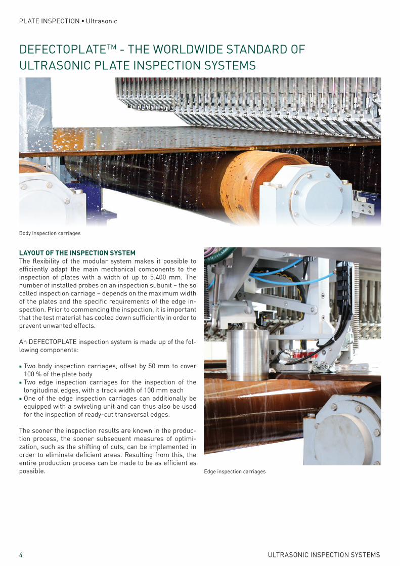
LAYOUT OF THE INSPECTION SYSTEMThe flexibility of the modular system makes it possible to efficiently adapt the main mechanical components to the inspection of plates with a width of up to 5.400 mm. The number of installed probes on an inspection subunit – the so called inspection carriage – depends on the maximum width of the plates and the specific requirements of the edge in-spection. Prior to commencing the inspection, it is important that the test material has cooled down sufficiently in order to prevent unwanted effects.
An DEFECTOPLATE inspection system is made up of the fol-lowing components:
■ Two body inspection carriages, offset by 50 mm to cover 100 % of the plate body
■ Two edge inspection carriages for the inspection of the longitudinal edges, with a track width of 100 mm each
■ One of the edge inspection carriages can additionally be equipped with a swiveling unit and can thus also be used for the inspection of ready-cut transversal edges.
The sooner the inspection results are known in the produc-tion process, the sooner subsequent measures of optimi-zation, such as the shifting of cuts, can be implemented in order to eliminate deficient areas. Resulting from this, the entire production process can be made to be as efficient as possible.
Body inspection carriages
Edge inspection carriages
5ULTRASONIC INSPECTION SYSTEMS
PLATE INSPECTION ■ Ultrasonic
HIGHLY PRECISE INSPECTION DATA
INSPECTION SYSTEM DATA
Number of probes, plate body inspection
plate width 50 mm
Number of probes, edge inspection 2 (4)
Inspection velocity ≤ 60 m/min
Distance between two inspection shots
≤ 1.0 mm
SENSITIVITY
Total thickness range (except dead zone)
FBH3
Limited thickness range FBH2
DEAD ZONE
On the ultrasound incidence side ≤ 1.5 mm
Opposite the ultrasound incidence side
≤ 1.5 mm
UNINSPECTED AREAS, PLATE BODY INSPECTION SYSTEM
Plate head at 60 m/min (15 m/min) 150 mm (70 mm)
Plate tail 80 mm
Longitudinal edge 20 mm – 70 mm
UNINSPECTED AREAS, LONGITUDINAL EDGE INSPECTION SYSTEM
Plate head at 60 m/min (15 m/min) 150 mm (70 mm)
Plate tail 80 mm
Longitudinal edge ≤ 10 mm
UNINSPECTED AREAS, TRANSVERSE EDGE INSPECTION SYSTEM
Plate head of the immobile plate ≤ 10 mm
Plate tail of the immobile plate ≤ 10 mm
System availability ≤ 98.5 %
Inspection performance(e.g. for a plate of 4 m * 28 m)
> 200 m2/min
6 ULTRASONIC INSPECTION SYSTEMS
PLATE INSPECTION ■ Ultrasonic
FLEXIBLE SOLUTIONS FOR EVERY SITE
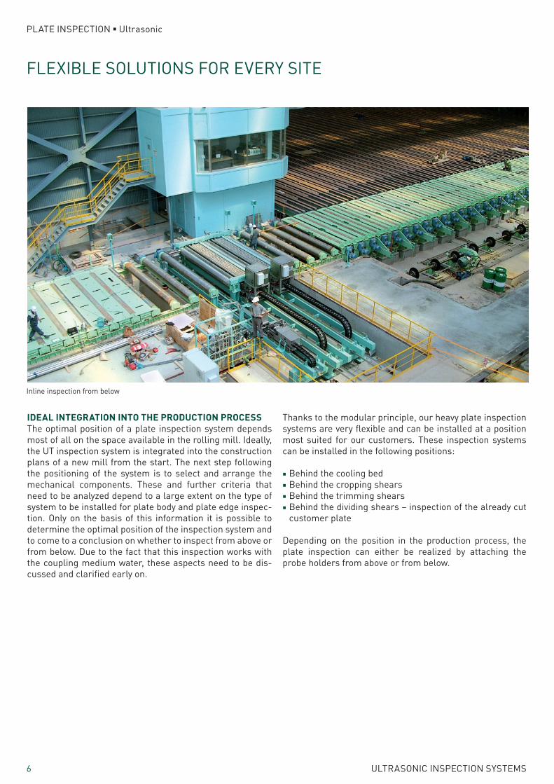
IDEAL INTEGRATION INTO THE PRODUCTION PROCESSThe optimal position of a plate inspection system depends most of all on the space available in the rolling mill. Ideally, the UT inspection system is integrated into the construction plans of a new mill from the start. The next step following the positioning of the system is to select and arrange the mechanical components. These and further criteria that need to be analyzed depend to a large extent on the type of system to be installed for plate body and plate edge inspec-tion. Only on the basis of this information it is possible to determine the optimal position of the inspection system and to come to a conclusion on whether to inspect from above or from below. Due to the fact that this inspection works with the coupling medium water, these aspects need to be dis-cussed and clarified early on.
Thanks to the modular principle, our heavy plate inspection systems are very flexible and can be installed at a position most suited for our customers. These inspection systems can be installed in the following positions:
■ Behind the cooling bed ■ Behind the cropping shears ■ Behind the trimming shears ■ Behind the dividing shears – inspection of the already cut customer plate
Depending on the position in the production process, the plate inspection can either be realized by attaching the probe holders from above or from below.
Inline inspection from below
7ULTRASONIC INSPECTION SYSTEMS
PLATE INSPECTION ■ Ultrasonic
BENEFITS OF VARIOUS SOLUTIONS
BENEFITS OF THE INSPECTION FROM BELOW ■ Unobstructed view of the roller table and the incoming and outgoing plates.
■ Plates can be transferred, aligned and brought into and out of position without a problem.
■ The maintenance of the roller table rollers, including the removal and installation of the rollers, is facilitated.
■ Below the roller table level, the probes are better protect-ed from rippled plates with a strongly deformed head and tail zone.
■ The installed crane will not face any obstructions from sys-tem components.
■ Better access for regular maintenance and repair, which especially applies to the probes and the probe holders.
■ The distance between the plate body and the probes is al-ways the same and does not depend on the thickness of the plate.
■ Less soiling of the probes by the inspection of hot plates. ■ For the system type inspecting from below, a service pit is required in which the inspection carriages are installed. On the other side, for the plate inspection from above, the entire system is installed above the roller table.
BENEFITS OF THE INSPECTION FROM ABOVE ■ Substantially less soiling since the system parts are less exposed to the coupling water.
■ Better accessibility of the mechanical parts, since the overall layout is exposed.
■ Less work on the foundations and less modifications of the roller table are required as most of the work can be done outside the roller table area.
■ Thin plates need not be held down by mechanical hold-down rollers or magnetic rollers.
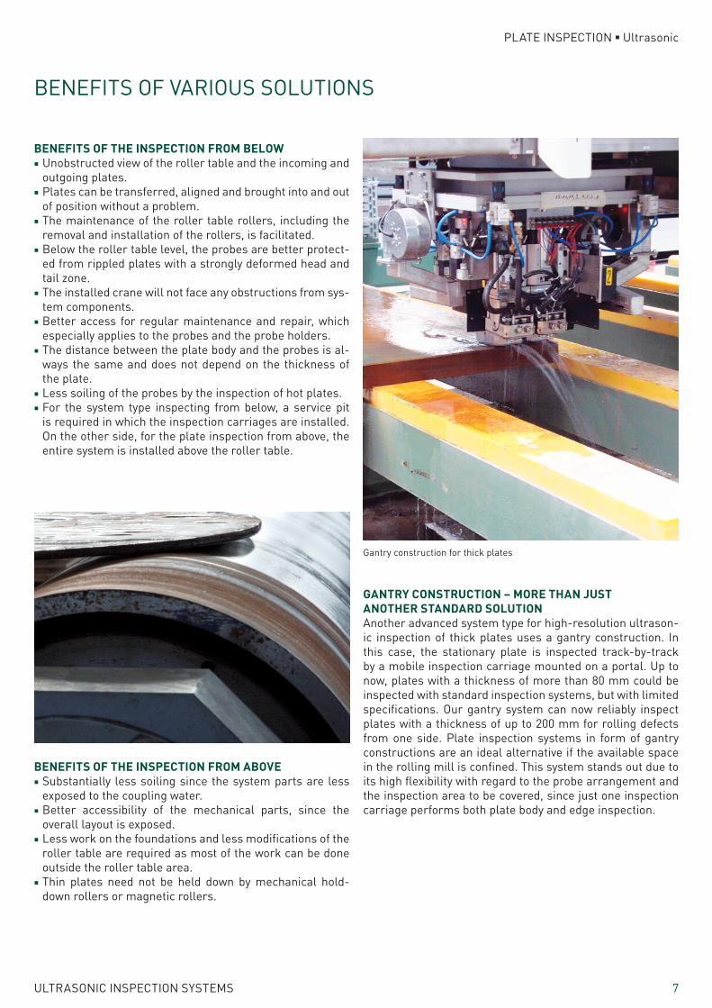
GANTRY CONSTRUCTION – MORE THAN JUST ANOTHER STANDARD SOLUTIONAnother advanced system type for high-resolution ultrason-ic inspection of thick plates uses a gantry construction. In this case, the stationary plate is inspected track-by-track by a mobile inspection carriage mounted on a portal. Up to now, plates with a thickness of more than 80 mm could be inspected with standard inspection systems, but with limited specifications. Our gantry system can now reliably inspect plates with a thickness of up to 200 mm for rolling defects from one side. Plate inspection systems in form of gantry constructions are an ideal alternative if the available space in the rolling mill is confined. This system stands out due to its high flexibility with regard to the probe arrangement and the inspection area to be covered, since just one inspection carriage performs both plate body and edge inspection.
Gantry construction for thick plates
8 ULTRASONIC INSPECTION SYSTEMS
PLATE INSPECTION ■ Ultrasonic
TESTING WITH DEFECTOPLATETM
The ultrasonic inspection system is an integral part of the overall manufacturing process and, as such, has to be in-tegrated into the other systems in the production process. Data from systems prior to inspection such as plate dimen-sions and shapes directly affect the inspection, making the electronic integration of and communication to the ultrason-ic inspection system absolutely necessary. Just as the me-chanical components are optimally adjusted to the produc-tion process, the inspections results should also ideally be used for the subsequent process steps.
INSPECTION TASK AND EVALUATIONThe DEFECTOPLATE inspection systems provide the custom-er with information on the quality of the inspected plate. This information is both objective and reproducible. The number, dimension, depth and position of any defect in a rolled heavy plate is automatically determined and compared with the quality standards set prior to inspection.
EFFICIENT ULTRASOUND ELECTRONICSThe most recent ultrasound electronics have been designed especially for multi-channel applications such as the in-spection of heavy plates. These electronics are based on modular hardware that can be adapted to a whole variety of inspection tasks.
HIGHLY SENSITIVE PROBES FOR HIGHER RESOLUTIONThe pulse echo mode using TR probes ensures best results for the inspection over the entire thickness of a plate. The probes have been designed especially for the inspection of heavy plates, the sensitivity being particularly high in the im-mediate area of the probe. The high sensitivity is achieved with the optimized design and the use of composite materi-al for the transducer. The standard version consists of one transmitting and three receiving transducers (T1R3). These are arranged in a probe casing which can be used for plates with a thickness of up to 100 mm. Probes with one trans-mitting and four receiving transducers (T1R4) have an even higher resolution and can be used to inspect plates with a thickness of up to 150 mm. These are wide-band probes which ensure a high axial resolution.
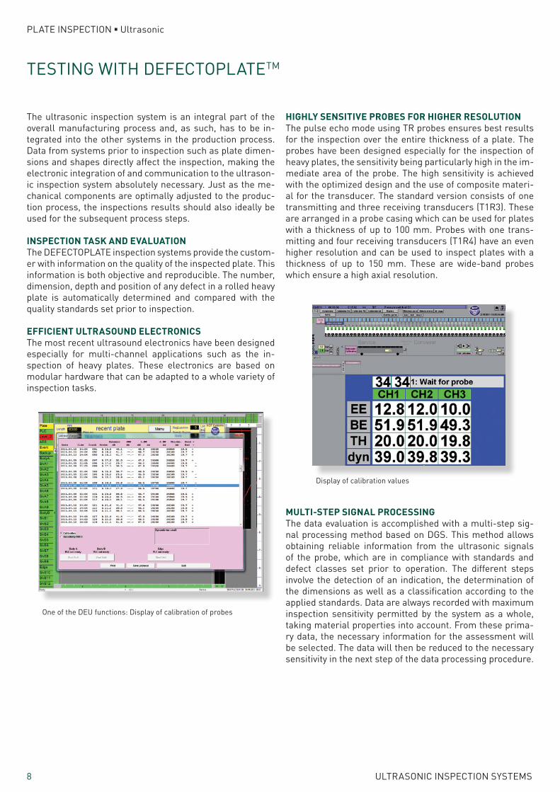
One of the DEU functions: Display of calibration of probes
Display of calibration values
MULTI-STEP SIGNAL PROCESSINGThe data evaluation is accomplished with a multi-step sig-nal processing method based on DGS. This method allows obtaining reliable information from the ultrasonic signals of the probe, which are in compliance with standards and defect classes set prior to operation. The different steps involve the detection of an indication, the determination of the dimensions as well as a classification according to the applied standards. Data are always recorded with maximum inspection sensitivity permitted by the system as a whole, taking material properties into account. From these prima-ry data, the necessary information for the assessment will be selected. The data will then be reduced to the necessary sensitivity in the next step of the data processing procedure.
9ULTRASONIC INSPECTION SYSTEMS
PLATE INSPECTION ■ Ultrasonic
AUTOMATIC EVALUATION SYSTEM
DATA EVALUATION UNIT (DEU)The DEU is a user interface for visualizing ultrasonic signals (A-scan) and for controlling the entire inspection system. Like other system components, the DEU is based on a mod-ular, Windows® and net-based software structure. Among other things, the program supports the graphical presen-tation of the UT inspection results. The data obtained from the inspection are immediately displayed in graphs (C-scan) or as a defect list. This allows evaluating the inspected plate with regard to the predefined standards in real time with the Automatic Evaluation System (AES).
Concerning maintenance and operator support, further functions are, for example, the activation of a self test and the automatic calibration of the probes. Furthermore, an A-scan of selected channels can be displayed and the anal-ysis of the raw data from after the inspection can be carried out. All these options can be controlled either by hand or automatically.
AUTOMATIC EVALUATION SYSTEM (AES)The AES combines the indications from individual inspection tracks to spatial imperfections with characteristic values (length, width, depth, amplitude, etc.) which cover several tracks. The individual imperfections will be compared with the corresponding standards and a decision will be made whether the plate complies with these standards or not. This automatic evaluation facilitates the operation, since manu-al evaluations tasks are subjective, hardly reproducible and difficult to record. Therefore, the rolling mill can be used to full capacity.
Aside from comparing the customer plate to international standards, plant or customer specific evaluation parame-ters for classification can be defined as well. The results of the evaluation are already available for further processing by the time the inspected plate leaves the inspection system.
The data recorded during the inspection with the highest possible sensitivity of the system will be saved so that it can be re-evaluated according to different standards and classes at any time without the need of re-inspecting the plate.
In addition to the electric storage, the protocols and individ-ual C-scans can also be printed. Furthermore, C-scans of up to four zoomed sections from defined areas can be displayed and printed as attachments.
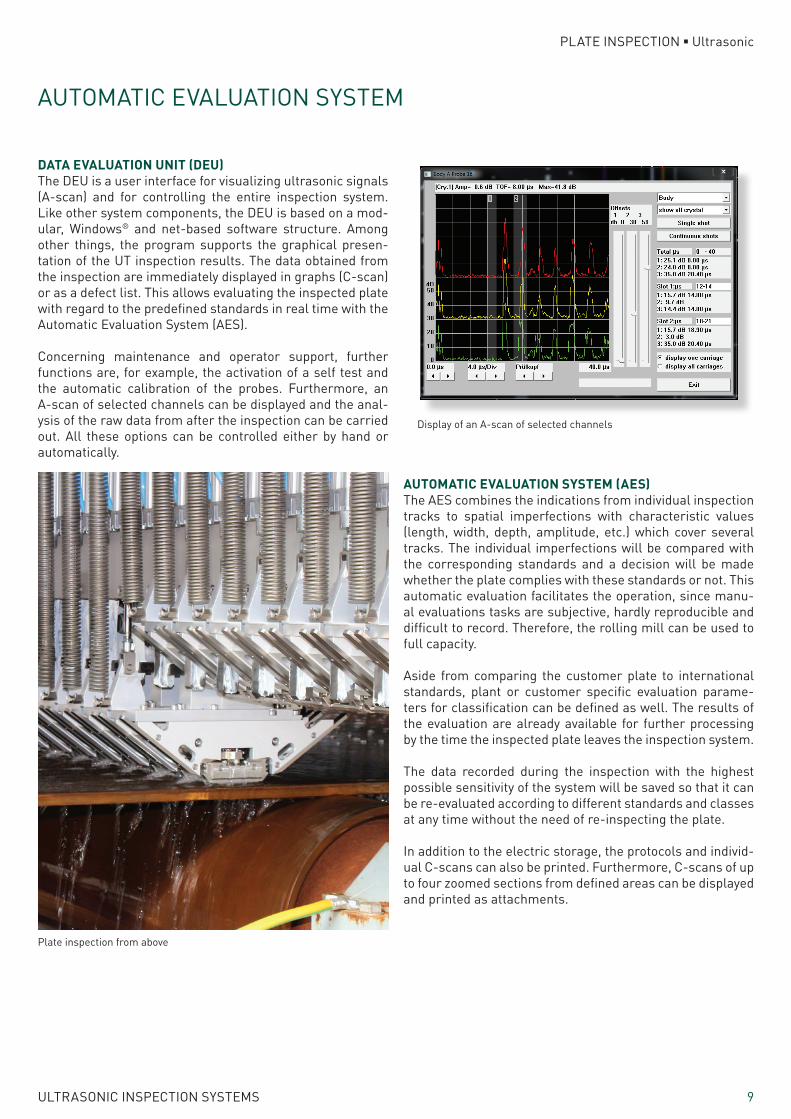
Plate inspection from above
Display of an A-scan of selected channels
10 ULTRASONIC INSPECTION SYSTEMS
PLATE INSPECTION ■ Ultrasonic
ANALOG FUNCTIONS ■ Background noise, cross talk attenuation ■ Frequency response ■ Dynamic range (Uemin, Uemax) ■ Pulse response ■ Real-time resolution ■ Vertical linearity deviation ■ Linearity deviation of the dB regulator ■ Setting range of the pre-amplifier
TRANSMITTING PULSE DATA ■ Pulse repetition frequency ■ Amplitude ■ Pulse rise time, pulse decay time ■ Transmitting pulse width ■ Internal resistance of the transmitter
FOERSTER CUSTOMER SERVICE
We at FOERSTER consider ourselves as partners of our cus-tomers. Therefore, our customer service does not just begin once the inspection system has been supplied. As specialist in non-destructive testing, we advise our customers com-prehensively in all issues concerning a modern inspection solution using ultrasound. Our customer support begins in the preliminary stages in order to determine the exact needs of inspection of our customers and to define the specifica-tions of an inspection system meeting these needs.
After putting the system into service, we also ensure that it provides the results our customers expect in return for their investment. Our after sales service not only supplies spare and wear parts, but is also the partner to contact if the sup-port of one of our experienced service engineers is needed to solve possible technical problems.
In addition to the standard products related to plates, among our strong points are those developments based on the needs of our customers to master demanding inspections tasks that cannot be solved with conventional inspection systems. This applies to both our software solutions and hardware developments. Contact us: we are sure to find a solution for your inspection task.
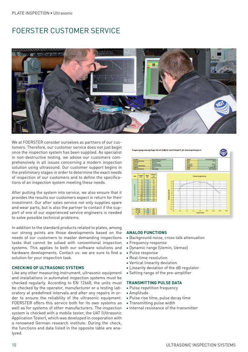
CHECKING OF ULTRASONIC SYSTEMSLike any other measuring instrument, ultrasonic equipment and installations in automated inspection systems must be checked regularly. According to EN 12668, the units must be checked by the operator, manufacturer or a testing lab-oratory at predefined intervals and after any repairs in or-der to ensure the reliability of the ultrasonic equipment. FOERSTER offers this service both for its own systems as well as for systems of other manufacturers. The inspection system is checked with a mobile tester, the UAT (Ultrasonic Application Tester), which was developed in cooperation with a renowned German research institute. During the check, the functions and data listed in the opposite table are ana-lyzed.

11ULTRASONIC INSPECTION SYSTEMS
PLATE INSPECTION ■ Ultrasonic
TEST PLATES ACCORDING TO CUSTOMER SPECIFICATIONSWe can supply our customers with specially prepared test plates for setting up and regularly checking the system. Ref-erence test results are provided for every test plate. During regular checks, these can be compared to actually obtained test results. These plates, provided with artificial reference defects, are kept on-site in the vicinity of the inspection sys-tem. In this way, they are available with minimum delay.
Optimized analysis of the inspection signals with our Automatic Evaluation System
The test plates, which can be certified on demand, are man-ufactured according to the customer’s specifications. They are usually already part of the whole delivery scope and therefore dispatched at the same time as the inspection system. In order to be able to react even quicker and more flexible in providing test plates, we offer our customers the choice of having these plates supplied either from Europe or from our Asian works.
In addition, we can provide a mobile groove milling and drill-ing machine which allows for the test plates to be prepared at the customer’s facilities.

Reg.-No. 001159 QM08
Institut Dr. Foerster GmbH & Co. KG
Division TestsystemsIn Laisen 7072766 ReutlingenGermany
+49 7121 140 [email protected]
Institut Dr. Foerster GmbH & Co. KGNDT Systems
Am Hasenbiel 776297 StutenseeGermany
10 SUBSIDIARIES
REPRESENTATIVES IN MORE THAN 50 OTHER COUNTRIES
WORLDWIDE SALES AND SERVICE OFFICES
foerstergroup.de
Pri
nted
in G
erm
any
Edi
tion
06/
2015
® R
egis
tere
d Tr
adem
ark
© C
opyr
ight
Inst
itut
Dr.
Foe
rste
r G
mbH
& C
o. K
G
Sub
ject
to
chan
ge