Embed Size (px)
Citation preview

DEFECTOTHERM����
Sensor system T 60 2.863
Sensor system T 60 with guide units
� Sensor system for hot wire testing up to+1200 °C
� For wire or rod diameters from around 5 to60 mm
� Coil carrier T 60 for water-cooled LMD-Therm coils
� Online testing directly in the rolling line
� Designed for maximum production speeds
� Fast dimension change in the line
� Fast conversion for line operation “Withouttesting”
� Full functionality without sliding table
� Operator control end can be adapted locallywithout special tools

Application
The sensor system T 60 has been optimized fortesting rolled wire and rods with material tem-peratures of up to +1200 °C in the production line.The sensor system T 60 operates in accordancewith the eddy current method in conformity withEN 12084.
For many years now, non-destructive testing ofwire with eddy current during production hasbeen a recognized means of ensuring the qualityof the wire and of optimizing the productionprocess.
The eddy current method can also be employedunder extreme conditions: material speed up to150 m/s and wire temperature in excess of1000 °C – the material temperature of ferromag-netic materials must be safely above the Curiepoint to rule out disturbances from permeabilityfluctuations. Modern wire lines produce coils withwire lengths of up to 12 km. This is why analysisand interpretation of the test signals has priorityover the localization of individual flaws. The aimsof analysis:
• Determining and logging the delivery quality ofthe individual wire coil and/or of an entireorder
• Determining changes and irregularities in theproduction process to be able to intervene ingood time
Signal evaluation is based on a distinction ac-cording to signal amplitude, separate counting ofsignals and depiction of the frequency distribu-tion over the wire length and over several wiresfor a trend analysis. The test units can be inte-grated into quality and production data acquisitionsystems.
Water-cooled eddy current differential coils areused for signal generation. The reliability – signal
stability and useful life – of the coil systems iscrucially important.
Qualified assistance in the choice of the optimuminstallation location and in definition of the rightcoil diameter can be expected from an experi-enced system supplier. Useful test signals canonly be expected if we succeed in adapting thecoil system properly to the conditions of the rollmill.
To arrive at optimum test results, the wire mustbe guided through the test coil centrically andwithout vibrations. Radial wire movement de-pends on the choice of test location and on theoverall conditions of the rolling line. The coil car-rier features entry and exit guide nozzles that areadapted to the diameter of the test coils so as tolargely prevent any damage to them.
Therefore, if conditions in the rolling line aregood, a guide unit with adapted guide nozzlebefore the coil carrier frequently suffices to ar-rive at good test results.
Under unfavorable conditions it may be neces-sary to install a further guide unit after the coilcarrier or even to work with roller guides insteadof the nozzle guide. (Roller guides are generallyoffered by roll mill manufacturers, e.g. the Mor-gardshammar company offers suitable rollerguides.)
The eddy current differential coil is used in con-junction with DEFECTOMAT® test and evalua-tion equipment operated in a through-type modeof operation.
The electronic circuitry of the device is designedfor testing speeds up to 150 m/s so as to reliablycover all rolling speeds.
Test coils with nominal diameters from 7 to65 mm are available.
Figure 1: Sensor system T 60, installed in a hot wire line
Structure

Coil carrier
Figure 2: Coil carrier, operating side Figure 3: Coil carrier, ports for cooling media
The Coil carrier accommodates the test coil andthe nozzles.
The test coil and the nozzles for coil protectionare inserted in the coil carrier from above. Withoutthe need for tools, the coil carrier can be retooledwithin the shortest of times:
� Undo cable and cooling medium � coil cou-pling.
� Undo the toggle screw.� Tilt up the stirrup.� Remove the nozzles and coil.� Insert the new coil and nozzles – or NT (Not-
Test) guide tube if testing is not to take place.� Close and lock the stirrup.
The owner generally provides a guide tube withan adapted geometry.
The operating side and the connection ports forthe cooling media and the compressed air can beadapted to the respective on-site situation.
Figure 4: Coil carrier open
Figure 5: Coil carrier without coil and nozzles Figure 6: Coil carrier, adapting operating side
Test coils

Figure 7: Test coils size I Figure 8: Test coils size II
Hot wire testing is realized with the proven LMD-Therm coils, sizes I + II, selected for the testedmaterial diameter.
I: (7), 8, 9, 10, 11, 12, 13, 15, 17, 20, 23 mm
II: 26, 29, 32, 35, 38, 41, 44, 47, 50, 53, 56,59, 62, 65 mm
(Please inquire about intermediate dimen-sions)
Figure 9: Test coils size III (special application)
Special application:
In some cases, eddy current testing is also usedto test hot pipes and rods. A coil holder III for theuse of Therm coil sizes III – 65 to 125 mm – andcorresponding nozzles are available for this pur-pose.
The connection sockets for the coil cable and thetwo plug-in connectors for water cooling aremounted on the coil cover.
LMD-Therm coils can be repaired by the cus-tomer. Service instructions are provided for thispurpose.
Therm coils in the size I series are inserted in thecoil carrier T 60 with the “Therm coils size I coiladapter”.
Figure 11: Coil adapter Therm coil size I,see Figure 10 for details of installation
Figure 10: Nozzle-coil centring adapter

Entry and exit nozzles
Figure 12: Guide unit with guide nozzle
Guide unit
The diameters of the surface-hardened entry andexit nozzles are adapted to the test coils.
Standard recommendation: Ø entry and exit noz-zle 1 mm less than the Therm coil.
By means of centering adapters, nozzles and thetest coil are centered in the coil carrier and theyare fixed in position by hinged stirrups.
Compressed air for the removal of deposits canbe blown into the entry nozzle through three radi-ally entering holes offset at 120°. As air is alwaysfed to at least one radial hole, the nozzles can berotated to prolong the operating time if wear hasoccurred owing to contact with the wire.
The compressed air supply is located on the op-eration end of the coil holder. It can optionally bedisplaced on the opposite side.
Entry nozzles are not suitable for catching thewire coming from the rolling line. This is why ei-ther a guide unit or a special, extended entrynozzle with a large funnel must be used beforethe entry nozzle.
Nozzle selection recommendation: same nominaldiameter for the entry and exit, but 1mm less thanthe nominal dimension of the Therm coil.
Same nominal dimension for guide nozzles andthe Therm coil.
In the T 60 test system, centricity can be im-proved and vibration of the test material can bereduced by means of additional, identical guideunits before and if necessary after the coil car-rier.
Guide nozzles
The guide nozzles with one-sided funnels areharmonized to the entry nozzles. The mount forthe guide nozzles (guide unit) is basically similarto the coil carrier, but air port is not necessary.
The nozzles are inserted in the mount fromabove and are fixed in place with a stirrup.
Figure 13: Coil carrier with two optional nozzle guide units, optional mounting plate
Entry
Supply for compressed air
Supply for cooling water

Alternative guides
Roller guide
As already mentioned, under unfavorable condi-tions there may be a need to use roller guidesinstead of nozzle guide units because these en-able optimum wire guidance and largely avoidsurface damage. As roller guides depend directlyon the rolled products, on the rolling line and on
the operating and maintenance personnel, how-ever, it is advisable to plan these in direct coor-dination with the respective roll mill outfitter; forexample, a modified version of the SR seriesfrom Morgardshammar is shown.
Figure 14: Coil carrier with roller guide, planned by the roll mill outfitter
NT guide tubes (No-Test)
In the event that testing is not to take place in theroll mill, NT guide tubes are available for bridgingthe coil carrier without the coil and one or twoguide units (substitute for a sliding table).
Coil dummy
The minimum possible nominal dimension for awire with specified diameter can be determinedwith a coil dummy that has the nominal dimen-sion of the coil and which is inserted in the coilcarrier.
Figure 15: NT guide tube in the coil carrier with twoguide units
Figure 16: NT coil dummy in the coil carrier
Cooling water accessories

To avoid thermal damage on the sensor systemduring hot wire testing, the test coil and the noz-zles are cooled with water.
With the aid of plug-in hoses, the coil, the coilcarrier, and, if applicable, the guide unit(s) arejoined together in a cooling system.
It is imperative to use purified industrial water asthe cooling water. The system must not be deac-tivated automatically in the event of an average. Itis also urgently advisable to provide a cleaningfilter on the entry side of the coil cooling watercircuit and a flow monitor on the exit side.
The optionally available cooling water accesso-ries include the cleaning filter, the flow monitor, adistributor and shut-off unit and hoses.
Thus, an adapted coolant installation can be setup on site.
If cooling water accessories and installation arerealized on-site, attention must be paid to en-suring that the cooling water quantity and thepressure in the cooling system do not exceed thespecified values.
To reduce material deposits such as scale in thetest coil, compressed air can be introduced intothe entry nozzle via a compressed air port on thecoil carrier.
During pauses in testing (wire gaps), a previ-ously connected valve (to be provided by thecustomer) can be used to shut off the air.
Figure 17: Cooling water accessories
Entry and exit nozzlesGuide nozzles
Test coil
Valve
Valve
Water entry
Distributor
Water reflux to sewer
Monitoring /Alarm unit(customer supplied)
Water entry with filter
Water circulation must beguaranteed also in case ofoperating breakdown!
Flow monitor

Test piece sensor
Controlled by an infrared test piece sensor fittedbefore the sensor system T 60, the dynamicsignal lock of the electronic testing unit sup-presses the start and end signals.
The infrared test piece sensor is installed in anyposition up to 10 m ahead of the test coil with adirect line of sight to the test piece.
Figure 18: Test piece sensor
Powder marking unit
On warm test material, flaws are marked with apowder marking unit, if necessary. Flaw markingsare possible up to test speeds of around 15 m/s.Attention must be paid to the fact that the inten-sity of paint application decreases as speed
increases. The essential function units consist ofa powder receptacle featuring an atomizer head,a pneumatic service unit and an electropneu-matical control unit.
Figure 19: Powder marking unit
Electronic testing unit
• DEFECTOMAT DS (see Leaflet DEFECTOMAT® DS 2.815)
Connecting cables
Connecting cables as detailed in the cable over-view diagram are needed to establish the electri-cal connection between the testing and evalua-tion unit and the sensor system with the testpiece sensor and marking unit. Figure 21 showsthe layout that is recommended. As the elec-tronic test unit does not feature any operatorcontrols whatever, it can be accommodated in aprotective housing in the proximity of the testinglocation and will only require accessibility forservicing.
The advantage of this arrangement is the shortlength of diverse cables, particularly of the coilcable, with resulting low interference (EMC). Thedistance from the operation unit, which is typi-cally set up in the control platform, can be sev-eral hundred meters. The connection betweentest electronics and operation unit is realized withan Ethernet cable. If distances are more than100 m the use of glass fiber cable is recom-mended.
Test pieces – Test equipment
To determine the sensitivity setting for selectedartificial test flaws and to check functioning, useis generally made of “cold” test pieces in a testequipment (rods featuring test flaws in a separatecoil and nozzle arrangement) which correspondto the “hot” test material in terms of their eddycurrent properties. The test pieces are movedmanually in the test equipment so as to ensurethat the test flaws in the test coil generate flawsignals. Communication between the test equip-ment and the operation unit at the control platformfor setting the suitable test parameters can beestablished with a second monitor or via FOER-STERnet with a second operation unit which evencan be connected temporary. Alternatively, aradio telephone connection can be established
between the control platform and the operator ofthe test equipment.
The test equipment consists of a separate coilholder T 60 with a pair of plastic protective noz-zles per test piece and a short additional coilcable. For good reproducibility of signal acquisi-tion, the nozzle diameter is adapted closely tothe test piece diameter.
The parameter settings determined with theartificial test flaws, in particular the test sensitiv-ity, serve only as guide values for the results thatcan be achieved online. These largely dependon the surface quality of the test material; theresulting interference level and the vibrations ofthe wire running at high speeds.
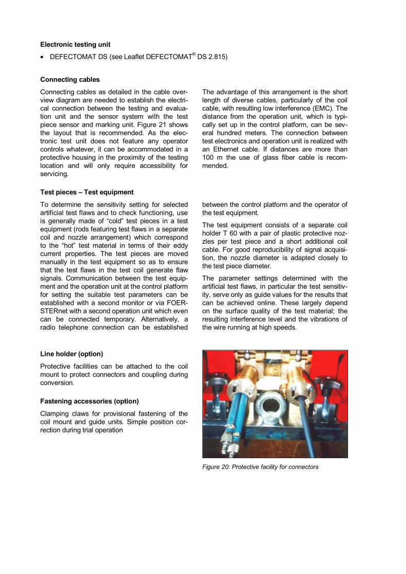
Line holder (option)
Protective facilities can be attached to the coilmount to protect connectors and coupling duringconversion.
Fastening accessories (option)
Clamping claws for provisional fastening of thecoil mount and guide units. Simple position cor-rection during trial operation
Figure 20: Protective facility for connectors

Technical data
Nominal diameter range (clear inner diameter) 7 to 65 mm
Diameter of test material 5 to 60 mm
1 to 100 kHz Nominal diameter < 29 mmTest frequencies for LMD-Therm coils
1 to 30 kHz Nominal diameter > 29 mm
Test object temperature up to +1200 °C 1
Testable material Fe, NFe, Aust.
Coil size I > 1,5 l/min
Coil size II > 2,5 l/min
Cooling water requirement(purified industrial water)
per nozzle approx. 2 l/min
Permissible temperature of the cooling water atthe outlet of test coil
+60 °C
Permissible pressure of the cooling water at theoutlet
preferably pressureless, max. 0,5 bar
Compressed air connection port 2 to 6 bar
Quality of the compressed air no special requirements
Testing speed up to 150 m/s
Test piece sensor Infrared-Sensor
Test piece sensor� test coil distance max. 10 mThe test piece must already have the nominaldimension at the location of the test piece sen-sor
Sensor system mounting level horizontally or slightly inclined, according torolling mill. Mounting flange always down! (If it ismounted other than in the permissible way, thereis a risk of air bubbles forming in the coolingwater circuit)
Dimensions of sensor systems see Figures 22 to 24
Mass of coil holder without nozzles and coil approx. 22 kg
1 Ferromagnetic material and material containing ferromagnetic components only at temperatures above the Curie point(cold points must be avoided)

Figure 21: General cable diagram DEFECTOMAT DS 2.815

Figure 22: Dimensions Coil carrier

Figure 23: Dimensions Guide unit

Figure 24: Dimensionsabove: Coil carrier with two Guide units and coilmid: Coil carrier with one Guide unitbelow: Coil carrier with two Guide unit and NT-Guide tube

Should you have any special problems please contact:
Institut Dr. Foerster GmbH & Co. KGDivision TS Semi-finished Product TestingIn Laisen 7072766 REUTLINGENGERMANYPhone +49 7121 140-270Fax +49 7121 [email protected]
�������������� ����������������������������
������������������
����� ��!�"#"$$ %�����
®�&����������������'©�(�)����������*���+����������,��%�-�(���.,