Embed Size (px)
Citation preview

UNCLASSIFIED
Defense Technical Information CenterCompilation Part Notice
ADP010955TITLE: Technologies for Future Precision Strike Missile Systems - MissileDesign Technology
DISTRIBUTION: Approved for public release, distribution unlimited
This paper is part of the following report:
TITLE: Technologies for Future Precision Strike Missile Systems [lesTechnologies des futurs systemes de missiles pour frappe de precision]
To order the complete compilation report, use: ADA394520
The component part is provided here to allow users access to individually authored sectionsf proceedings, annals, symposia, etc. However, the component should be considered within
[he context of the overall compilation report and not as a stand-alone technical report.
The following component part numbers comprise the compilation report:ADPO10951 thru ADP010959
UNCLASSIFIED

5-1
Technologies for Future Precision Strike Missile Systems -Missile Design Technology
Eugene L. FleemanAerospace Systems Design Laboratory
School of Aerospace EngineeringGeorgia Institute of Technology
Atlanta, Georgia 30332-0150, United StatesEugene.Fleeman(asdl. gatech.edu
Abstract/Executive Summary
This paper provides an assessment of the state-of-the-art and considerations of missile design technology forfuture precision strike missile systems. Benefits of missile design technology include new advanced missileconcepts, identification of driving parameters, balanced subsystems, incorporation of new technologies, lightweight/low cost missiles, and launch platform compatibility. The paper discusses the missile design process,presents examples of simulation and spreadsheet conceptual design computer programs, provides missileconfiguration design criteria, and lists references that are applicable to missile design technology.
Missile Design Process
Figure 1 shows the relationship of missile design to the development process of research, technology, andacquisition. Conceptual design is most often conducted during the exploratory development phase of missiledevelopment. A primary objective of exploratory development is to investigate and evaluate technologyalternatives. The advanced technology development phase of missile development is intended to mature theenabling technologies of key subsystems. Although conceptual design may also be conducted duringadvanced development, preliminary design methods are usually more appropriate. Preliminary designcontinues during advanced development demonstration of the prototype missile. Following successfuldemonstration of a prototype, the program moves into engineering and manufacturing development (EMD).At this point more detail design methods are appropriate for the operational missile. However, the assessmentof possible future block upgrades may require the reintroduction of preliminary design and conceptual designactivities.
Conceptual design and sensitivity studies should be conducted early in the exploratory development process,and continued into advanced development. Many of the cost and performance drivers may be locked induring the conceptual design phase. It is important to quickly evaluate a large number of alternatives thatcover the feasible design solution space.
An indicator of design maturity is the number of drawings that are required to describe the design.Conceptual design may be characterized by approximately five drawings for each concept, describing perhapsfive subsystems. A large number of alternative concepts, perhaps ten, are in evaluation during conceptualdesign. Conceptual design drawings include the missile overall dimensions, major subsystems layout, andmay also list the major subsystems mass properties. The next step is preliminary design. Preliminary designdrawings of a prototype missile are usually characterized by up to 100 drawings, with greater detail andshowing up to 100 components. Preliminary design drawings have fully dimensioned subsystems, inboardlayouts showing the subsystems, individual subsystem and component drawings, and dimension tolerances.A fewer number of alternative missile concepts, perhaps four, are under evaluation during preliminary design.Following preliminary design, the next step is detail design. Detail design for EMD usually requires morethan 100 drawings and often has more than 1,000 drawings. EMD drawings have even greater detail,including drawings of each part, detailed work assembly instructions and descriptions of the manufacturingprocesses. During EMD there is usually only one concept by a sole source contractor.
Paper presented at the RTO SCI Lecture Series on "Technologies fJr Future Precision StrikeMissile Systems ", held in Tbilisi, Georgia, 18-19 June 2001; Bucharest, Romania, 21-22 June 2001;
Madrid, Spain, 25-26 June 2001; Stockholm, Sweden, 28-29 June 2001, and published in RTO-EN-018.
5-2
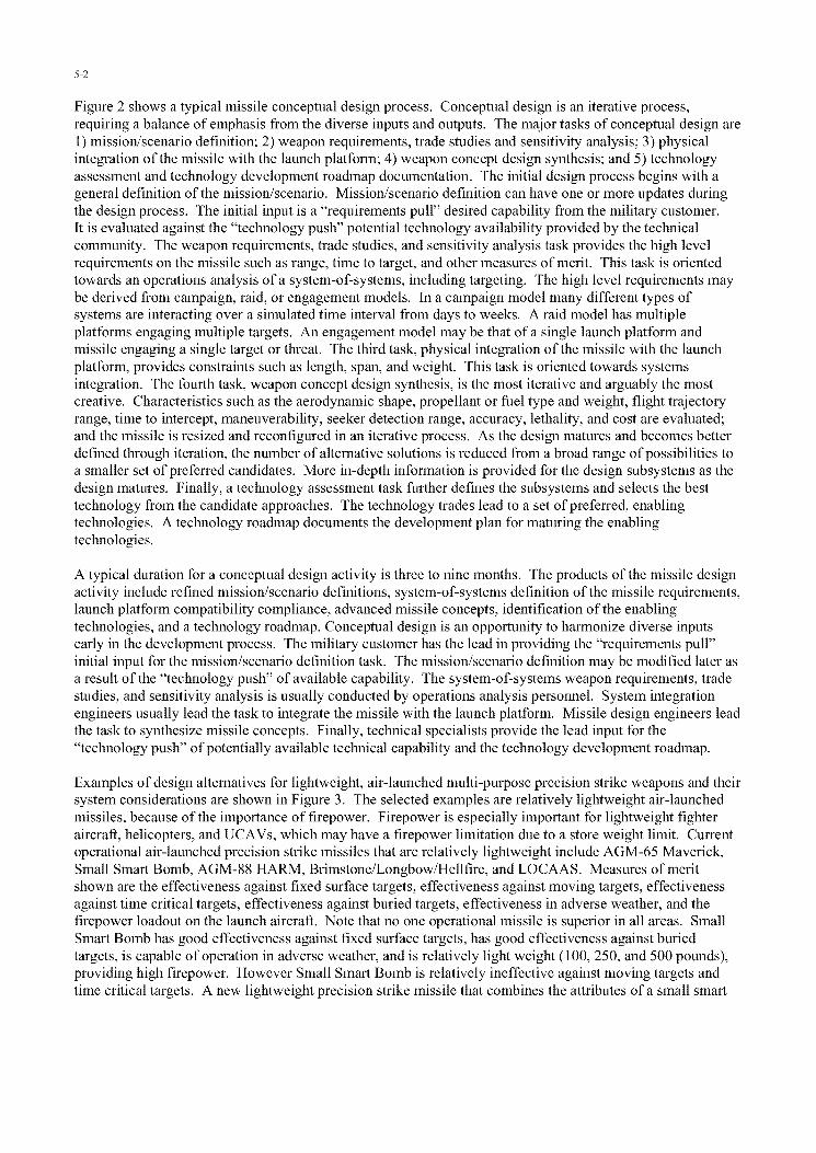
Figure 2 shows a typical missile conceptual design process. Conceptual design is an iterative process,requiring a balance of emphasis from the diverse inputs and outputs. The major tasks of conceptual design are1) mission/scenario definition; 2) weapon requirements, trade studies and sensitivity analysis; 3) physicalintegration of the missile with the launch platform; 4) weapon concept design synthesis; and 5) technologyassessment and technology development roadmap documentation. The initial design process begins with ageneral definition of the mission/scenario. Mission/scenario definition can have one or more updates duringthe design process. The initial input is a "requirements pull" desired capability from the military customer.It is evaluated against the "technology push" potential technology availability provided by the technicalcommunity. The weapon requirements, trade studies, and sensitivity analysis task provides the high levelrequirements on the missile such as range, time to target, and other measures of merit. This task is orientedtowards an operations analysis of a system-of-systems, including targeting. The high level requirements maybe derived from campaign, raid, or engagement models. In a campaign model many different types ofsystems are interacting over a simulated time interval from days to weeks. A raid model has multipleplatforms engaging multiple targets. An engagement model may be that of a single launch platform andmissile engaging a single target or threat. The third task, physical integration of the missile with the launchplatform, provides constraints such as length, span, and weight. This task is oriented towards systemsintegration. The fourth task, weapon concept design synthesis, is the most iterative and arguably the mostcreative. Characteristics such as the aerodynamic shape, propellant or fuel type and weight, flight trajectoryrange, time to intercept, maneuverability, seeker detection range, accuracy, lethality, and cost are evaluated;and the missile is resized and reconfigured in an iterative process. As the design matures and becomes betterdefined through iteration, the number of alternative solutions is reduced from a broad range of possibilities toa smaller set of preferred candidates. More in-depth information is provided for the design subsystems as thedesign matures. Finally, a technology assessment task further defines the subsystems and selects the besttechnology from the candidate approaches. The technology trades lead to a set of preferred, enablingtechnologies. A technology roadmap documents the development plan for maturing the enablingtechnologies.
A typical duration for a conceptual design activity is three to nine months. The products of the missile designactivity include refined mission/scenario definitions, system-of-systems definition of the missile requirements,launch platform compatibility compliance, advanced missile concepts, identification of the enablingtechnologies, and a technology roadmap. Conceptual design is an opportunity to harmonize diverse inputsearly in the development process. The military customer has the lead in providing the "requirements pull"initial input for the mission/scenario definition task. The mission/scenario definition may be modified later asa result of the "technology push" of available capability. The system-of-systems weapon requirements, tradestudies, and sensitivity analysis is usually conducted by operations analysis personnel. System integrationengineers usually lead the task to integrate the missile with the launch platform. Missile design engineers leadthe task to synthesize missile concepts. Finally, technical specialists provide the lead input for the"technology push" of potentially available technical capability and the technology development roadmap.
Examples of design alternatives for lightweight, air-launched multi-purpose precision strike weapons and theirsystem considerations are shown in Figure 3. The selected examples are relatively lightweight air-launchedmissiles, because of the importance of firepower. Firepower is especially important for lightweight fighteraircraft, helicopters, and UCAVs, which may have a firepower limitation due to a store weight limit. Currentoperational air-launched precision strike missiles that are relatively lightweight include AGM-65 Maverick,Small Smart Bomb, AGM-88 HARM, Brimstone/Longbow/Hellfire, and LOCAAS. Measures of meritshown are the effectiveness against fixed surface targets, effectiveness against moving targets, effectivenessagainst time critical targets, effectiveness against buried targets, effectiveness in adverse weather, and thefirepower loadout on the launch aircraft. Note that no one operational missile is superior in all areas. SmallSmart Bomb has good effectiveness against fixed surface targets, has good effectiveness against buriedtargets, is capable of operation in adverse weather, and is relatively light weight (100, 250, and 500 pounds),providing high firepower. However Small Smart Bomb is relatively ineffective against moving targets andtime critical targets. A new lightweight precision strike missile that combines the attributes of a small smart
5-3
bomb with the capability to handle moving targets and time critical targets would be more robust. Examplesof technologies that provide robustness to handle a broad range of targets include:
"* GPS/INS precision guidance"* SAR or imaging millimeter wave seeker for adverse weather homing"* Ducted rocket propulsion for higher speed and longer range"* Low drag airframe for higher average speed and longer range"* Multi-mode kinetic energy/blast fragmentation warhead"* Light weight subsystems for a lighter weight missile
Figure 4 shows the iterative process used for conceptual design synthesis. Based on mission requirements, aninitial baseline from an existing missile with similar propulsion is established. It is used as a starting point toexpedite the design convergence. Advantages of a baseline missile include the prior consideration of balancedsystem engineering for the subsystems and the use of an accurate benchmark based on existing test data(e.g., wind tunnel data). Changes are made in the baseline missile aerodynamics, propulsion, weight, andflight trajectory to reflect the new requirements of the new missile concept. The new conceptual design isevaluated against its flight performance requirements (e.g., range, time to target, maneuver footprint). Theaerodynamics portion of the conceptual design process is an investigation of alternatives in configurationgeometry. The output of the aerodynamics calculation is then inputted to the propulsion system design to sizethe propulsion system. Propulsion sizing includes providing sufficient propellant or fuel to meet the range andtime-to-target requirements. The next step is to estimate the weight of the new missile with its modifiedaerodynamics and propulsion. Much of this activity is focussed on structural design, which is sensitive tochanges in flight performance. Following the weight sizing, flight trajectories are computed for the newmissile. The range, terminal velocity, maneuverability, and other flight performance parameters are thencompared with the mission flight performance requirements. If the missile does not meet the flightperformance requirements, it is resized and reiterated. After completing a sufficient number of iterations tomeet the flight performance requirements, the next step is evaluating the new missile against the othermeasures of merit and constraint requirements. If the missile does not meet the requirements, the design ischanged (alternative configuration, subsystems, technologies) and resized for the next iteration and evaluation.
A synthesized missile will differ from the starting point baseline in several respects. For example, the wingarea may have been resized to meet the maneuverability requirement. The tail area may have been resized tomeet static margin and maximum trim angle of attack requirements. The rocket motor or the ramjet enginemay have been modified to improve its efficiency at the selected design altitude or Mach number.Additionally, the length of the propulsion system may have been changed to accommodate additionalpropellant/fuel necessary to satisfy flight range requirements. The design changes are reflected in revisions tothe mass properties, configuration geometry, thrust profile, and flight trajectory for the missile. Typically,three to six design iterations are required before a synthesized missile converges to meet the flightperformance requirements.
Figure 5 is an example of baseline data that is used in conceptual design sizing. The example is based on achin inlet, integral rocket ramjet. Other examples could be based on the precision strike missiles shown inFigure 4. In the upper left of the figure is an illustration of a configuration drawing of the baseline missile.The configuration drawing is a dimensioned layout, with an inboard profile showing the major subsystems(guidance, warhead, fuel, booster/engine, and flight control surfaces). In the upper center of the figure areexamples of tables for a missile weight statement and geometry data. Missile weight and center-of-gravitylocation are provided for launch, booster burnout, and engine burnout flight conditions. Weight and geometrydata are also provided for the major subsystems. The upper right corner of the figure is an illustration of adescription of ramjet internal flow path geometry. The internal flow path geometry data includes the inletdesign capture area and the internal areas of the inlet throat, diffuser exit, flame holder plane, combustor exit,nozzle throat, and nozzle exit. Examples of aerodynamic data plots are illustrated in the left center section ofthe figure. Aerodynamic data for the ramjet baseline covers angles of attack up to 16 degrees and Machnumbers up to 4.0. Aerodynamic coefficients and derivatives include zero-lift drag coefficient (CDo), normal
force coefficient (CN), pitching moment coefficient (C,,), pitching moment coefficient control effectivenessderivative (C s), and normal force coefficient control effectiveness derivative (CN6 ). Examples of ramjet

5-4
propulsion thrust (T) and the ramjet specific impulse (Isp) are shown in the center of the figure. Thrust andspecific impulse are functions of Mach number and fuel-to-air ratio. Rocket booster propulsion thrust, boostrange and burnout Mach number are illustrated in the right center of the figure as a function of launch Machnumber and altitude. The left bottom section of the figure shows the maximum flight range of the ramjetbaseline. Maximum flight range is a function of launch Mach number, launch altitude, cruise Mach number,and cruise altitude. Finally, the right bottom section of the figure is an example of the sensitivity of designparameters on maximum flight range. Sensitivity parameters include inert weight, fuel weight, zero-lift dragcoefficient, lift-curve-slope derivative (CL), ramjet thrust, and ramjet specific impulse. The sensitivity studyin the example was conducted for cruise flight conditions ranging from Mach 2.4, sea level to Mach 3.0, 60Kfeet altitude.
Figure 6 is a summary of the aerodynamic configuration sizing parameters for precision strike missiles. Flightcondition parameters that are most important in the design of tactical missiles are angle of attack (a), Machnumber (M), and altitude (h). For the aerodynamic configuration, the missile diameter and length have a firstorder effect on characteristics such as missile drag, subsystem packaging available volume, launch platformintegration, seeker and warhead effectiveness, and body bending. Another configuration driver is nosefineness, an important contributor to missile drag for supersonic missiles. Also, nose fineness affects seekerperformance, available propellant length, and missile observables. Another example is missile propellant/fueltype and weight, which drive flight performance range and velocity. The aerodynamic configuration winggeometry and size are often set by maneuverability requirements. Stabilizer geometry and size are oftenestablished by static margin requirements. In the flight control area, the geometry and size of the flight controlsurfaces determine the maximum achievable angle of attack and the resulting maneuverability. Finally, thethrustprofile determines the missile velocity time history.
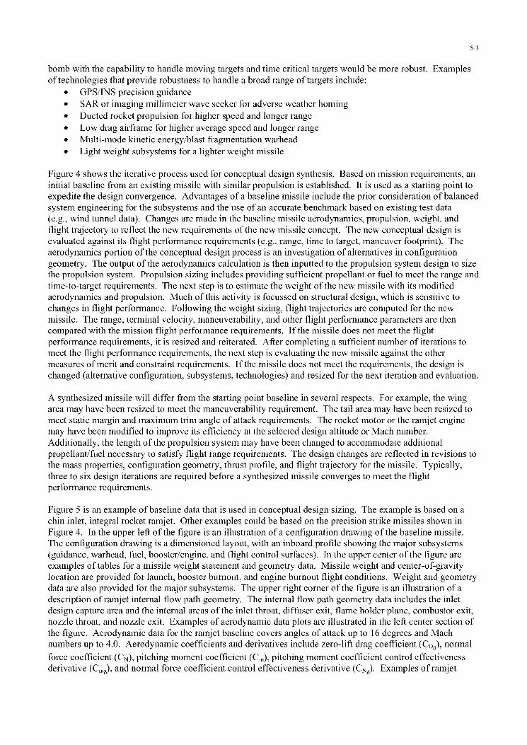
The flight trajectory evaluation activity under missile concept synthesis requires consideration of the degreesof freedom to be simulated. Figure 7 compares the simulation modeling degrees of freedom that are usuallyused in conceptual design with the degrees of freedom that are appropriate for preliminary design. Asdiscussed previously, conceptual design is the rapid evaluation of a large range of alternatives. It requires thatthe design methods be fast, easy to use, and have a broad range of applicability. The simplest model, oftenacceptable for the conceptual design of high-speed missiles, is one degree of freedom. One degree of freedommodeling requires only the zero-lift drag coefficient, thrust, and weight. Analytical equations can be used tomodel a one-degree-of-freedom simulation. Other models used for conceptual design are two degrees offreedom point mass modeling, three degrees of freedom point mass modeling, three degrees of freedom pitchmodeling and four degrees of freedom roll modeling. In the 4DOF roll modeling the normal force, axialforce, pitching moment, rolling moment, thrust, and weight are modeled for a rolling airframe missile.Finally, missile simulation during preliminary design is usually modeled in six degrees of freedom (6DOF).The 6DOF simulation includes three forces (normal, axial, side), three moments (pitch, roll, yaw), thrust, andweight. Missile degrees of freedom greater than 6DOF describe the structure bending modes. Because mosttactical missiles are relatively stiff, modeling at greater than 6DOF is usually not required for aerodynamiccontrol missiles but may be required for impulse reaction jet control missiles.
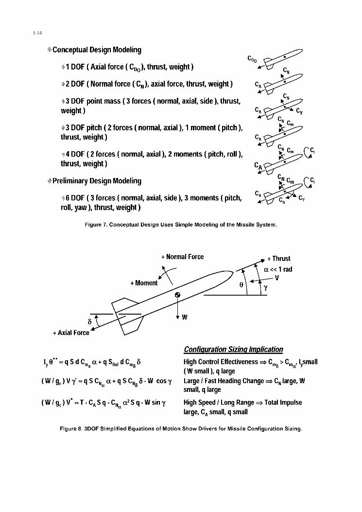
It is instructive to examine the equations of motion for missile design drivers. Figure 8 shows the equations ofmotion for three degrees of freedom with pitch modeling. The figure shows the missile angular acceleration
(0), rate of change in the flight path angle (y), and the rate of change in the velocity (V). The configurationsizing implication from examining the angular acceleration equation shows the importance of controleffectiveness. High control effectiveness is provided by high pitching moment control effectiveness (Cm6),low static stability (Cm.J, small moment of inertia (Iy), and large dynamic pressure (q). A small moment ofinertia is a characteristic of a lightweight missile. The second equation shows the design drivers for missilemaneuverability. High maneuverability is the capability to make large and rapid changes in the flight pathangle. This occurs for large normal force coefficient (CN), lightweight (W), and large dynamic pressure (q).Large CN is achievable through large values of CN•, U, C1N, and 6. Implications of the third equation are
missile speed and range. High-speed and long-range are provided by large total impulse, or the integral ofthrust for the burn time duration (JTdt). There is also payoff for flight range in using higher densitypropellant/fuel. Higher density propellant/fuel increases the total impulse of a volume limited propulsion

5-5
system. The third equation also shows that low axial force coefficient (CA) and low dynamic pressure providelonger range. Axial force coefficient is approximately equal to the zero-lift drag coefficient (CD0).
Examples of Missile Conceptual Design Simulation Programs
Two fundamental requirements for computer programs used in conceptual design are fast turnaround time andease of use. Fast turnaround is necessary to search a broad solution space with a sufficient number ofiterations for design convergence. A good design code connects the missile physical parameters directly to atrajectory code that calculates flight performance. The conceptual design methods should be simple physics-based methods, incorporating only the most important, driving parameters. Baseline missile data should beimbedded in the code, to facilitate startup. More detailed computational methods are used later in preliminarydesign, when the number of alternative geometric, subsystem, and flight parameters has been reduced to asmaller set of alternatives. As an example, it is inappropriate to use computational fluid dynamics (CFD) inconceptual design. The mathematical considerations of CFD (e.g., mesh size, time interval, numericalstability, turbulence modeling, smoothing) are impediments to the fast turnaround time that is required forconceptual design. Similarly, a 6DOF trajectory simulation is inappropriate during conceptual design for theconvenient evaluation of guided flight. The development of the required autopilot for 6DOF guided flight istime consuming, diverting emphasis from other more appropriate considerations. Similarly, missileoptimization codes are generally inappropriate for conceptual design. Optimization in conceptual design isbest left to the creativity and the intuition of the designer. Optimization codes work best when there is acontinuous smooth variation in parameters, which is usually not the case in conceptual design. For example,optimization codes do not work well in comparing ramjet propulsion versus rocket propulsion. The CFD,6DOF guided flight trajectory simulations, and optimization codes have seductive "precision." However moreoften than not their accuracy in conceptual design is worse than simpler methods. Simpler aerodynamic andsimulation methods, combined with a well defined baseline missile and the designer's creativity and intuitionare a preferable approach for alternatives selection, sizing, and optimization. They are invariably moreaccurate and robust.
Advanced Design of Aerodynamic Missiles (ADAM).
The following discussion of the ADAM missile simulation program is provided as an example of a computerprogram that generally meets the conceptual design criteria of fast turnaround, ease of use, and applicable to abroad range of configurations and flight conditions. ADAM is a DOS code that runs on a PC. ADAM mayhave compatibility problems with higher speed computers. It may require a compatible timing hardwareemulation setting, to reduce the rate at which the computer's timer sends timing. The ADAM aerodynamicspredictions are based on slender body theory and linear wing theory. The aerodynamic methods coversubsonic to hypersonic Mach numbers and angles of attack up to 180 degrees. The ADAM aerodynamicsmodule calculates force and moment coefficients, static and dynamic stability derivatives, trim conditions,control effectiveness, and center of pressure location. Modeling of the equations of motion can be in three,four, five, or even six degrees of freedom (unguided flight). The three degrees of freedom flight trajectorymodel runs faster than real time. A thirty-second time of flight requires about eight seconds of run time. The6DOF flight trajectory simulation is used to analyze the nutation/precession modes of missiles during theirunguided portion of flight, as well as unguided bombs and unguided projectiles. It requires longer run time.For homing missiles, proportional guidance is used as well as other guidance laws. The input to the ADAMflight trajectory module is provided automatically by the aerodynamics module, simplifying the user input.The benchmark missiles used in the aerodynamics module have corrected coefficients and derivatives basedon wind tunnel data. Greater than fifty input parameters are available. The input default is the baselinemissile parameters, simplifying the input data preparation.
The baseline missiles in ADAM include air-to-air (e.g., Archer), surface-to-air (e.g., Patriot), air-to-surface(e.g., Hellfire), and surface-to-surface (e.g., ATACMS) missiles. The aerodynamic modeling of the bodyincludes the diameter, nose configuration (geometry, fineness, bluntness), body bulge, boattail, and length.The body cross section may be circular or elliptical. Up to three surfaces (stabilizers, wings, and controls) canbe specified. The geometric modeling of each surface includes: the location, leading edge root and tip station,span, trailing edge root and tip station, thickness, control surface deflection limit, and the number of surfaces.

5-6
The program models the missile center-of-gravity variation from launch to burnout. For propulsion, the thrustis modeled as a two value thrust profile, of a given time duration. The propellant weight of each thrust-timephase can also be specified. The target can be fixed or moving. Down range and cross range of the target arespecified, as well as the target altitude and velocity. Launch conditions for the missile are specified, includingaltitude, velocity, launch angle, and the guidance law. The output of the three degrees of freedom pitchsimulation modeling includes a drawing of the missile geometry with dimensions, aerodynamic coefficientsand derivatives, center of pressure location, flight performance parameters (velocity, trim angle of attack,acceleration, range, trim control surface deflection) versus time, and missile miss distance.
Tactical Missile Design (TMD) Spreadsheet.
Another computer technique suitable for conceptual design is spreadsheet analysis. Figure 9 shows the designparameters of the Tactical Missile Design (TMD) Spreadsheet. The TMD Spreadsheet runs in Windows on aPC. It has modules that follow the conceptual missile design tasks outlined in the figure. Based on externalmission requirements (e.g., maximum range, minimum range, average velocity, measures of merit, andconstraints), a baseline design is selected from the baseline missile spreadsheet module. Currently there aretwo possible baselines: a rocket powered missile, similar to the Sparrow AIM-7 missile, and a ramjet missile.The configuration, subsystem, and flight performance characteristics of the ramjet missile baseline wereillustrated previously in Figure 5. The rocket missile baseline has a similar level of detail in its configuration,subsystem, and flight performance data.
Following the definition of mission requirements and the selection of a baseline configuration in the baselinespreadsheet module, the aerodynamics spreadsheet module is exercised. The aerodynamics spreadsheetmodule calculates zero-lift drag coefficient, normal force coefficient, aerodynamic center location, pitchingmoment control effectiveness, lift-to-drag ratio, and the required tail stabilizer surface area. The output datafrom the aerodynamics spreadsheet module, along with other default data from the baseline missile, are inputinto a propulsion spreadsheet module. The methodology used to calculate the aerodynamics of a missile bodyare based on slender body theory for the linear low angle of attack contribution and blended with cross flowtheory at high angles of attack. It is applicable for all angles of attack, from zero to 180 degrees. The methodused in calculating aerodynamics of missile fixed surfaces (e.g., wings, strakes, stabilizers) and movablesurfaces (e.g., canards, tails) is based on linear wing and slender wing theory at low angle of attack andblended with Newtonian impact theory at high angles of attack.
The propulsion spreadsheet module provides an estimate of powered range, velocity, thrust, and specificimpulse. For a ramjet, the output also includes total pressure recovery in the inlet. Rocket motor thrust andspecific impulse are based on the isentropic flow equations, adjusted for the change in specific heat ratio withtemperature. Incremental velocity and range are based on the one-degree of freedom equation of motion. Theramjet thrust and specific impulse predictions include the forebody and cowl oblique shocks and the inletnormal shock losses in total pressure.
After redesigning the aerodynamic configuration and propulsion system, a weight spreadsheet is used to revisethe missile weight. The weight spreadsheet module includes an estimate of aerodynamic heating, surfacetemperature versus time, required airframe and motor case thickness, buckling stress, bending moment, motorcase stress, and the density/weight of subsystems. Missile system weight scaling is provided by the densityrelationship, diameter, and length. Scaling of the weights of subsystems is provided by the density andvolume relationships. Material data (e.g., density, stress-strain versus temperature) are also provided.Predictions are made of aerodynamic heating and surface temperature rate. Finally, missile body bucklingstresses due to bending moment and axial loads, motor case stress, and required motor case thickness arecalculated.
The flight trajectory spreadsheet module has analytical expressions for one degree and two degrees of freedomtrajectories. The output includes flight range, thrust required for steady flight, steady climb velocity, steadydive velocity, turn radius, velocity and range at the end of boost, velocity and range at the end of coast, seekerlead angle for proportional homing guidance, required launch range, missile time of flight, and F-pole range.Flight trajectory methods are based on closed-form analytical methods. Cruise range prediction is based on

5-7
the Breguet range equation. Thrust required is estimated for steady cruise, steady climb, and steady dive.Turn radius, boost and coast velocity, boost and coast range, missile homing lead angle, launch range, andF-pole range (relative range between the launch platform and the target when the missile impacts the target)are also calculated.
Finally, the designer compares the output of the flight trajectory spreadsheet module against mission flightperformance requirements. If the missile design does not meet the flight performance requirements, theprocess is repeated until the requirements are satisfied. The modularity of the spreadsheet and the defaultbaseline missile data allow the designer to easily modify the input for the next iteration.
Once flight performance requirements are met, the measures of merit and constraints are then evaluated. Themeasures of merit spreadsheet module calculates parameters for warhead lethality, miss distance,survivability, and cost. Output parameters for the warhead lethality include warhead blast pressure, killprobability, number of warhead fragments impacting the target, warhead fragment velocity, kinetic energywarhead penetration, and missile kinetic energy impacting the target for hit-to-kill missiles. Outputparameters for the missile miss distance include missile time constant, missile miss distance due to headingerror, and missile miss distance due to a maneuvering target. Output parameters for the missile survivabilityinclude detection range. Finally, the output parameters for missile cost include missile production cost due toweight and missile production cost due to the learning curve.
Again, the missile design is iterated until the measures of merit and constraints (such as launch platformintegration) are satisfied.
Verification of the TMD Spreadsheet was based on comparing the source code with the equations from theTactical Missile Design textbook, comparing results with the ADAM code, and also comparing the resultswith the examples in the Tactical Missile Design textbook. The rocket and ramjet baselines, which are basedon test data, were used in the verification of the TMD Spreadsheet.
Configuration Conceptual Design Sizing Criteria
Table 1 shows conceptual design configuration sizing criteria. The table has fourteen configuration designcriteria related to the areas of flight performance and guidance & control. Configuration design criteriarelated to flight performance include missile body fineness ratio, nose fineness ratio, boattail ratio, cruisedynamic pressure, missile homing velocity, ramjet combustion temperature, oblique shocks prior to the inletnormal shock, and inlet spillage. A design criterion for the missile body fineness ratio (length-to-diameterratio) is that it should be between 5 and 25, to harmonize tradeoffs of drag, subsystem packaging availablevolume, launch platform integration, seeker and warhead effectiveness, and body bending. The nose fineness(nose length-to-diameter ratio) for supersonic missiles should be approximately two to avoid high drag at highspeed without degrading seeker performance. Boattail diameter ratio (boattail diameter-to-maximum missilediameter ratio) should be greater than 0.6 for supersonic missiles to avoid increased drag at high speed. Adesign criterion for efficient cruise flight is that the dynamic pressure be less than 1,000 pounds per squarefoot. Missile velocity should be at least 50 percent greater than the target velocity to capture the target.Ramjet combustion temperature should be greater than 4,000 degrees Fahrenheit for high specific impulse andthrust at Mach number greater than 3.5. Efficient inlet integration for supersonic missiles requires at least oneoblique shock prior to the inlet normal shock, for good inlet total pressure recovery at Mach numbers greaterthan 3.0. For Mach numbers greater than 3.5, at least two oblique shocks prior to the inlet normal shock aredesirable for inlet total pressure recovery. Finally, the forebody shock wave should impact the inlet cowl lipat the highest Mach number cruise condition, to minimize the spillage drag at lower Mach number.
Configuration design criteria related to guidance & control include the flight control actuator frequency, trimcontrol power, stability & control derivatives cross coupling, airframe time constant, missile maneuverability,and proportional guidance ratio. Body bending frequency in the first mode should be greater than twice theflight control actuator frequency if possible, to avoid the complication and risk of notch filters. Trim controlpower (trim angle of attack-to-control surface deflection ratio) should be greater than 1 for maneuverability.Stability & control derivatives cross coupling should be less than 30 percent for efficient dynamics. The

5-8
missile airframe time constant should be less than 0.2 second for precision accuracy (3 meters). Contributorsto a low value of the airframe time constant include high maneuverability capability, neutral static margin,high rate control surface actuators, low dome error slope, and a low noise seeker. Missile maneuverabilityshould be at least three times the target maneuverability, for small miss distance. Finally, the proportionalguidance ratio should be between 3 and 5 to minimize miss distance. Values less than 3 result in excessivetime to correct heading error, while values greater than 5 make the missile overly sensitive to noise input fromthe seeker and the dome error slope.
Summary/Conclusions
Missile design is a creative and iterative process that includes system-of-systems considerations, missilesizing, and flight trajectory evaluation. Because many of the cost and performance drivers may be "locked in"early during the design process, the emphasis of this text has been on conceptual design.
Missile design is an opportunity to harmonize diverse inputs early in the missile development process. Themilitary customer, operations analysts, system integration engineers, conceptual design engineers, technicalspecialists, and others work together in harmonizing the mission/scenario definition, system-of-systemsrequirements, launch platform integration, missile concept synthesis, and technology assessment/roadmaps.
Missile conceptual design is a highly integrated process requiring synergistic compromise and tradeoffs ofmany parameters. The synthesis of an effective compromise requires balanced emphasis in subsystems,unbiased tradeoffs, and the evaluation of many alternatives. It is important to keep track of assumptions tomaintain traceable results. Starting with a well-defined baseline that has similar propulsion and performanceexpedites design convergence and provides a more accurate design.
Conceptual design is an open-ended problem and has no single right answer. The available starting pointinformation is never sufficient to provide only one solution. The design engineer makes assumptions incoming up with candidate concepts, subsystems, and technologies to satisfy mission requirements and coverthe solution space. Weighting of the most important measures of merit is required in coming up with a cost-effective solution. The military customer buy-in is important in achieving a consensus weighting of the mostimportant measures of merit. Trade studies are conducted to investigate the impact of design parameters.Sensitivity analyses are also conducted to evaluate the effects of uncertainty in the design and the benefit ofnew technology. The missile is designed for robustness to handle risk and uncertainty of both a deterministicand a stochastic nature.
Finally, a good conceptual design code is a physics-based code that connects the missile geometric, physical,and subsystem performance parameters directly into a flight trajectory evaluation. Good conceptual designcodes do not automatically change the design or resize automatically. It is best that the missile designer makethe creative decisions.
Bibliography of Missile Design Related Reports
System Design
Fleeman, E.L., Tactical Missile Design, American Institute of Aeronautics and Astronautics, WashingtonD.C., 2001.Hindes, J.W., "Advanced Design of Aerodynamic Missiles (ADAM)," October 1993.Bithell, R.A., and Stoner, R.C., "Rapid Approach for Missile Synthesis," AFWAL TR 81-3022, Vol. 1,March 1982.Jerger, J.J., Systems Preliminary Design Principles of Guided Missile Design, D. Van Nostrand Company,Inc., Princeton, New Jersey, 1960."Missile.index," http://www.index.ne.jp/missile e/.AIAA Aerospace Design Engineers Guide, American Institute of Aeronautics and Astronautics, 1993.Chin, S.S., Missile Configuration Design, McGraw-Hill Book Company, New York, 1961.

5-9
Kinroth, G.D. and Anderson, W.R., "Ramjet Design Handbook," CPIA Publication 319 and AFWAL TR80-2003, June 1980.Mason, L.A., Devan, L., and Moore, F.G., "Aerodynamic Design Manual for Tactical Weapons," NSWCTR81-156, 1981.Schneider, S.H., Encyclopedia of Climate and Weather, Oxford University Press, 1996.Klein, L.A., Millimeter- Wave and Infrared Multisensor Design and Signal Processing, Artech House, Boston,1997.Nicholas, T. and Rossi, R., "US Missile Data Book, 1996," Data Search Associates, 1996.Fleeman, E.L. and Donatelli, G.A., "Conceptual Design Procedure Applied to a Typical Air-LaunchedMissile," AIAA 81-1688, August 1981.Nicolai, L.M., "Designing a Better Engineer," AIAA Aerospace America, April 1992.Ashley, H., Engineering Analysis of Flight Vehicles, Dover Publications, New York, 1974."Missile System Flight Mechanics," AGARD CP270, May 1979.Hogan, J.C., et al., "Missile Automated Design (MAD) Computer Program," AFRPL TR 80-21, March 1980.Rapp, G.H., "Performance Improvements With Sidewinder Missile Airframe," AIAA Paper 79-0091, January1979.Nicolai, L.M., Fundamentals ofAircraft Design, METS, Inc., San Jose, CA, 1984.Lindsey, G.H. and Redman, D.R., "Tactical Missile Design," Naval Postgraduate School, 1986.Lee, R. G., et al, Guided Weapons, Third Edition, Brassey's, London, 1998.Giragosian, P.A., "Rapid Synthesis for Evaluating Missile Maneuverability Parameters," 10th AIAA AppliedAerodynamics Conference, June 1992.Fleeman, E.L. "Aeromechanics Technologies for Tactical and Strategic Guided Missiles," AGARD Paperpresented at FMP Meeting in London, England, May 1979.Raymer, D.P., Aircraft Design, A Conceptual Approach, American Institute of Aeronautics and Astronautics,Washington D.C., 1989.Ball, R.E., The Fundamentals ofAircraft Combat Survivability Analysis and Design, American Institute ofAeronautics and Astronautics, Washington D.C., 1985.Eichblatt, E.J., Test and Evaluation of the Tactical Missile, American Institute of Aeronautics andAstronautics, Washington D.C., 1989."DoD Index of Specifications and Standards," http://www.dtic.mil/stinet/str/dodiss4 fields.html."Periscope," http://www.periscope.usni.com.Defense Technical Information Center, http://www.dtic.mil/."Aircraft Stores Interface Manual (ASIM)," http://www.asim.net."Advanced Sidewinder Missile AIM-9X Cost Analysis Requirements Description (CARD),"http://web2.deskbook.osd.mil/valhtml/2/2B/2B4/2B4TO1.htm.
Aerodynamics
"Technical Aerodynamics Manual," North American Rockwell Corporation, DTIC AD 723823, June 1970.Oswatitsch, K., "Pressure Recovery for Missiles with Reaction Propulsion at High Supersonic Speeds",NACA TM - 1140, 1948.Pitts, W.C., Nielsen, J.N., and Kaattari, G.E., "Lift and Center of Pressure of Wing-Body-Tail Combinationsat Subsonic, Transonic, and Supersonic Speeds," NACA Report 1307, 1957.Jorgensen, L.H., "Prediction of Static Aerodynamic Characteristics for Space-Shuttle-Like, and Other Bodiesat Angles of Attack From 0' to 180','' NASA TND 6996, January 1973.Hoak, D.E., et al., "USAF Stability and Control Datcom," AFWAL TR-83-3048, Global EngineeringDocuments, Irvine, CA, 1978."Nielsen Engineering & Research (NEAR) Aerodynamic Software Products,"http://www.nearinc.com/near/software.htm.Briggs, M.M., Systematic Tactical Missile Design, Tactical Missile Aerodynamics: General Topics, "AIAAVol. 141 Progress in Astronautics and Aeronautics," American Institute of Aeronautics, Washington, D.C.,1992.Briggs, M.M., et al., "Aeromechanics Survey and Evaluation, Vol. 1-3," NSWC/DL TR-3772, October 1977."Missile Aerodynamics," NATO AGARD LS-98, February 1979."Missile Aerodynamics," NATO AGARD CP-336, February 1983."Missile Aerodynamics," NATO AGARD CP-493, April 1990."Missile Aerodynamics," NATO RTO-MP-5, November 1998.

5-10
Nielsen, J.N., Missile Aerodynamics, McGraw-Hill Book Company, New York, 1960.Mendenhall, M.R. et al, "Proceedings of NEAR Conference on Missile Aerodynamics," NEAR, MountainView, CA, 1989.Nielsen, J.N., "Missile Aerodynamics - Past, Present, Future," AIAA Paper 79-1818, 1979.Dillenius, M.F.E., et al, "Engineering-, Intermediate-, and High-Level Aerodynamic Prediction Methods andApplications," Journal of Spacecraft and Rockets, Vol. 36, No. 5, September-October, 1999.Nielsen, J.N., and Pitts, W.C., "Wing-Body Interference at Supersonic Speeds with an Application toCombinations with Rectangular Wings," NACA Tech. Note 2677, 1952.Bums, K. A., et al, "Viscous Effects on Complex Configurations," WL-TR-95-3060, 1995."A Digital Library for the National Advisory Committee of Aeronautics," http://naca.1arc.gov.Spreiter, J.R., "The Aerodynamic Forces on Slender Plane-and Cruciform-Wing and Body Combinations",NACA Report 962, 1950.Bruns, K.D., Moore, M.E., Stoy, S.L., Vukelich, S.R., and Blake, W.B., "Missile Datcom," AFWAL-TR-91-3039, April 1991.Moore, F.G., et al, "Application of the 1998 Version of the Aeroprediction Code," Journal of Spacecraft andRockets, Vol. 36, No. 5, September-October 1999.
Propulsion
Cox, H.H. "Internal Aerodynamics," North American Aircraft Lecture Course, April 1968.Mahoney, J.J., Inlets for Supersonic Missiles, American Institute of Aeronautics and Astronautics,Washington, D.C., 1990.Sutton, G.P., Rocket Propulsion Elements, John Wiley & Sons, New York, 1986.Bonney, E.A., et al, "Propulsion, Structures and Design Practice," Principles of Guided Missile Design,D. Van Nostrand, Princeton, NJ, 1956."Tri-Service Rocket Motor Trade-off Study, Missile Designer's Rocket Motor handbook," CPIA 322,May 1980.Chemical Information Propulsion Agency, http://www.jhu.edu/~cpia/index.html.
Materials
Budinski, K.G. and Budinski, M.K., Engineering Materials Properties and Selection, Prentice Hall, NewJersey, 1999."Matweb's Material Properties Index Page," http://www.matweb.com."NASA Ames Research Center Thermal Protection Systems Expert (TPSX) and Material PropertiesDatabase", http://tpsx.arc.nasa.gov/tpsxhome.shtml.
Guidance & Control
Zarchan, P., Tactical and Strategic Missile Guidance, "AIAA Vol. 124 Progress in Astronautics andAeronautics," American Institute of Aeronautics and Astronautics, Washington D.C., 1990."Proceedings of AGARD G&C Panel Conference on Guidance & Control of Tactical Missiles," AGARDLS-52, May 1972.Heaston, R.J. and Smoots, C.W., "Precision Guided Munitions," GACIAC Report HB-83-01, May 1983.Donatelli, G.A. and Fleeman, E.L., "Methodology for Predicting Miss Distance for Air Launched Missiles,"AIAA-82-0364, January 1982.Bennett, R.R. and Mathews, W.E., "Analytical Determination of Miss Distances for Linear HomingNavigation Systems," Hughes Tech Memo 260, 31 March 1952.
Warhead
US Army Ordnance Pamphlet ORDP-20-290-Warheads, 1980.Carleone, J. (Editor), Tactical MissileWarheads, "AIAA Vol. 155 Progress in Astronautics and Aeronautics," American Institute of Aeronauticsand Astronautics, Washington, D.C., 1993.Christman, D.R. and Gehring, J.W., "Analysis of High-Velocity Projectile Penetration Mechanics," Journal ofApplied Physics, Vol. 37, 1966.

5-11
Research Technology L Acquisition
6.1 6.2 6.3A 6.3B 6.4 6.5 6.6
Basic Exploratory Adv. Tech Advanced Engr. & Man. Production SystemResearch Development * Development Development Development P Upgrades
- $0.1B - $0.3B - $0.9B - $0.5B - $1.0B - $6.1B - $1.2B
Maturity Level Conceptual Design Preliminary Design Detail Design Production Design
Drawings (tyoe) < 10 (subsystems) < 100 (components) > 100 ( parts) > 1000 ( parts)
Technology Technology Prototype Full Scale m rt BlocDevelopment Demonstration Demonstration Development Limited Block Upgrades
- 10 Years - 8 Years - 4 Years - 5 Years 2 Years - ~5"15Years
ProductionNote:
Total US DoD Research and Technology for Tactical Missiles = $1.8 Billion per yearTotal US DoD Acquisition ( EMD + Production + Upgrades) for Tactical Missiles = $8.3 Billion per yearTactical Missiles = 11% of U.S. DoD RT&A budgetUS Industry IR&D typically similar to US DoD 6.2 and 6.3A
Figure 1. Relationship of Level of Design to the Research, Technology, and Acquisition Process.
* Mission / Scenario UpdateDefinition
Weapon *ades enes il
Requirements,Trade Studies Initial Alt aselinand Sensitivity Re s nce SelectAnalysis
* Physical ni ia arriage/ Iteration
Integration Iair
Platform andWeapon
D Weapon Concept First-Cut Designs Design Studies Eval I RefineDesign Synthesis+ '- '
* Technology Initial Tech Initial Revised
Assessment and Tech Trades Roadmap RoadmapDev Roadmap
Note: Typical design cycle for conceptual design is usually 3 to 9 months
Figure 2. Conceptual Design of Precision Strike Missiles Requires Iteration.

5-12
Weapon Fixed Moving Time Buried Adverse Firepowe(6)Surface TargetS(2) Critical Target s4) Weathet5)TargetsO1 ) Targets"
3)
SExample New Missile 0 0
AG-65 0 0 0 0
Small Smart Bomb _ C-
AGM-88 0- --
_ Hellfire / Brimstone Q -Longbow
LOCAAS 0 - -
(1)- Large warhead desired. GPS / INS provides precision (3 meter accuracy.
(2)- Seeker required for terminal homing. Note:
(3)- High speed required = High payoff of rocket or ducted rocket propulsion and low drag. 0 Superior
(4)- Kinetic energy penetration required=* High impact speed * High payoff of low drag and long length. ( Good
(5)- GPS / INS, SAR seeker, and imaging mmW seeker have high payoff Q Average
(6) - Light weight required. Light weight also provides low cost - Poor
Figure 3. Examples of Design Alternatives for Light Weight Precision Strike Missiles.
Define Mission Requirements
( Establish Baseline ]
Aerodynamics
Propulsion
WeightResize
Trajectory
Meet NoPerformance?
IAlt Config / Subsystems I TechYes
Mesrs of Merit and Constraints No
Yes
Figure 4. Missile Concept Synthesis Requires Iteration.

5-13
Configuration Drawing Weight / Geometry Flow Path Geometry
Aerodynamics Ramjet Propulsion Rocket Propulsion
Flight Performance Range Sensitivity
Figure 5. Example of Precision Strike Missile Baseline Data.
Diameter P l StabilizerNose Fineness Geometry I Size
Wing Geometry I Size Thrust
Profile
Flight Conditions ( c, M, h )
Flight Control LengthGeometry I Size
Figure 6. Aerodynamic Configuration Sizing Parameters.
5-14
+Conceptual Design ModelingCDo
S1 DOF (Axial force (CDo), thrust, weight)
# 2 DOF (Normal force (CN), axial force, thrust, weight) CA
CN* 3 DOF point mass ( 3 forces ( normal, axial, side), thrust, Iweight) CA Cy
N
# 3 DOF pitch ( 2 forces ( normal, axial ), 1 moment ( pitch ),
thrust, weight) CA
# 4 DOF ( 2 forces ( normal, axial ), 2 moments ( pitch, roll), Cm CM C,
thrust, weight) CA
+Preliminary Design Modeling CmCM C,
6 DOF ( 3 forces ( normal, axial, side), 3 moments ( pitch, c- c"
roll, yaw), thrust, weight)
Figure 7. Conceptual Design Uses Simple Modeling of the Missile System.
+ Normal Force + Thrust
x << 1 rad+ Momentý( " V' a
+ Axial Force
Configuration Sizing ImplicationIy 0" = q S d Cm a + q SRef d Cm8 8 High Control Effectiveness * Cms > Cm I Ysmall
(W small), q large(W / gc) V " = qSCNa (x + qSCN,8-Wcos y Large / Fast Heading Change=* CNlarge, W
small, q large
(W / gc) V" = T- CA S q- CNa a 2S q- W sin y High Speed / Long Range = Total Impulse
large, CA small, q small
Figure 8. 3DOF Simplified Equations of Motion Show Drivers for Missile Configuration Sizing.

5-15
Define Mission Requirements [Flight Performance ( RpJ,,(, Rmifl, V~v,) IMOM, Constraints I
Establish Baseline [d, 1, IN' A, c, t, X~,1 W1, W~, WBc, I, Base line ( Rocket, Ramjet), Aero ( d, 1, IN'CO, CX, C I L/D, SJ) Rocket Propulsion ( p, C, IS c*, Tboost, Tsustain') ajtPoplin( 3
'C TV Thrust, Inlet Type, pt 2 pto) Weight ( Gya.,Guk~~) Trajectory ( R, V)
Aerodynamics Output[ C,),, CHI XACI Cm8 ,L/D, S 1
Propulsion Output[ R, I~,r Temiser pt, / pto Tbos Tsm "BosVesz
FWeight Output [Q, d~ki / dt, T~kifl, Psin I tskin' 0biuckling ,MB, ( Ft)motorr WI
TrajectoryOutput [R, TReqI VC, VD, RTI , y'AVboost VEC I Rcoast, LRL tf, RF-Pole
Flightormnc PefrmneReae
Nosets finenesss ratio 'N I d 2 if M>
Cr ise r dynami tcapesur qisl Deig 1000 S prasfetPraees
Missil hoin vrelcityo Strike 1.5l oniuaio ein rtra
Cofgramtio comusion Prmtemprtr e D ,0 eresig Fahrenhei
"GulidanPerf ontrole Related*Body biending frequenc 5 <IB/d 2 5A
Tri osefnntssroltpowe IN /> 1 fS oatabildity mcotero cratos coulin <30% /def<
* irframe tyaim pesostant q < 100. sec*Missile hmaneuverabiity NIM / T > 13
"Proporti & onarl gudnelratio3ed'<

This page has been deliberately left blank
Page intentionnellement blanche