Embed Size (px)
Citation preview

1 - 5th Ablation workshop - 2012
Definition of Ablation test-case series #3
5th Ablation Workshop Lexington, KY
Tom van Eekelen – LMS-Samtech, Belgium
Jean Lachaud – UARC/Univ. of California Santa Cruz, USA Alexandre Martin – University of Kentucky, USA
Ioana Cozmuta – FNMS, USA
2 - 5th Ablation workshop - 2012
§ Definition of the mandatory Test-case § Basic case (Test 3.1)
• Geometry definition • Material choice • Heat –load and boundary conditions
§ Initial results for the basic case § Modification of the basic case:
• Orthotropic TACOT material (Test 3.2) • Full 3D test-case (Test 3.3)
§ Discussion of the test-cases
§ Discussion of a possible re-entry probe test-case
Outline

3 - 5th Ablation workshop - 2012
§ Goal: to extend series #2 to 3D § Test 3.1
§ Iso-q specimen § Geometry well defined
§ Heat load distribution available § Material (iso-q + support): TACOT v2.2
Mandatory test-case
Milos F. and Chen Y.-K., Two-Dimensional Ablation, Thermal Response, and Sizing Program for Pyrolyzing Ablators.

4 - 5th Ablation workshop - 2012
§ Load & boundary conditions (Similar to Test 2.3) § Initial uniform temperature § Initial uniform pressure § Adiabatic/impermeable bottom surface
§ Radiation with the environment
§ Enthalpy flux (stagnation point)
§ Isotropic conductivity (axis-symmetric/3D)
Mandatory test-case
( )44wTTq −= ∞σε
( ) ( ) ( )[ ]wggwccHeeweHee hhBhhBCuhhCuq −+−+−= ''ρρ
12
'0
0
2
'0
−=
BH
H
eB
CC
λ
λ
5.0=λ
5 - 5th Ablation workshop - 2012
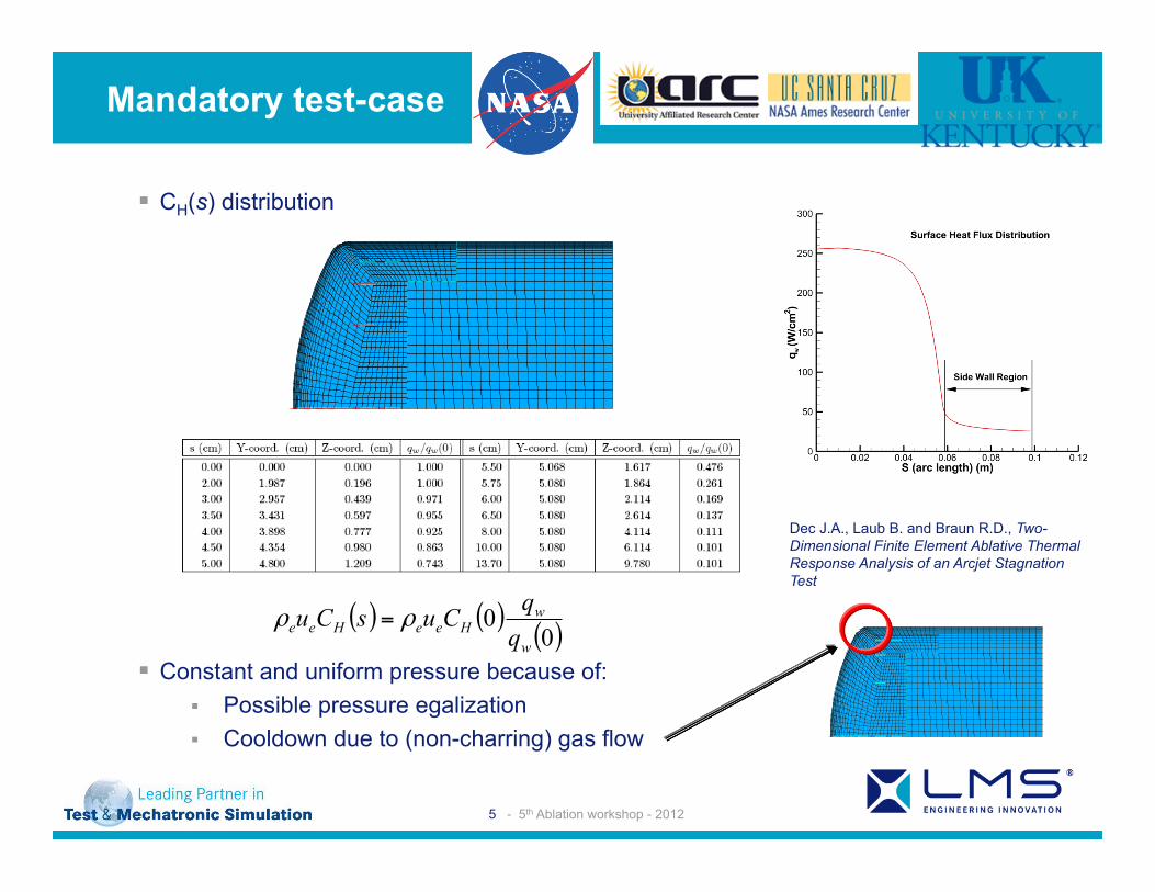
§ CH(s) distribution
§ Constant and uniform pressure because of: § Possible pressure egalization § Cooldown due to (non-charring) gas flow
Mandatory test-case
American Institute of Aeronautics and Astronautics
6
Table 1. Thermocouple locations Designation Depth, H
(cm) Radial Distance, r
(cm) TC1 0.381 0.0 TC2 0.762 0.0 TC3 1.143 0.0 TC4 1.524 0.0 TC5 2.286 0.0 TC6 3.048 0.0 TC7 2.286 2.54 TC8 2.286 3.81 TC9 2.286 4.45
TC10 3.048 4.45
V. Boundary Conditions The surface boundary conditions were obtained from a CFD solution of the coupon in the arcjet flow. The
centerline enthalpy for this test was 19.3 MJ/kg and the centerline heat flux was 255 W/cm2. The coupon was exposed to the flow for 40 seconds and allowed to cool. The cool down time for analysis purposes was 600 seconds. The heat flux varied across the surface of the coupon and also wrapped around the shoulder where there was non-trivial sidewall heating calculated. The distributed surface heat flux is shown in Fig. 2 and is applied to the external edges of the PICA and LI-2200.
In addition to the heat flux boundary condition, FEAR requires two supplementary boundary conditions. The first is a no flow boundary condition which is specified on the back edge of the PICA which interfaces with the LI-2200. The no flow boundary condition is required for the solution of the mass and momentum equations. The final required boundary conditions are to specify the zero displacement boundaries. The zero displacement boundaries are required for both the mesh movement scheme and the thermal stress calculation and need not be coincident. The zero displacement boundary condition for the mesh movement scheme encompasses all of the nodes and elements representing the LI-2200 since only the PICA is allowed to recede. The zero displacement boundary for the thermal stress calculation is the bottom edge of the LI-2200. Radiation in or out of any edge, (or surface in 3-D) is not a hard requirement, but is applied to all the external edges of the coupon except for the bottom edge of the LI-2200. The initial temperature is 20°C and the radiation sink temperature is 21.1°C.
Fig. 2 CFD predicted surface heat flux distribution.
VI. Results and Discussion FEAR was run in 2-D axisymmetric mode for the arcjet conditions and geometry described in Sections IV and
V. The temperature distribution at 40 seconds when the arcjet flow is cutoff is shown in Fig. 3. The temperature on
Test
cas
e 3.
1 -
TACO
T
X
Y Z
Dec J.A., Laub B. and Braun R.D., Two-Dimensional Finite Element Ablative Thermal Response Analysis of an Arcjet Stagnation Test
( ) ( )( )0
0w
wHeeHee q
qCusCu ρρ =
Test case 3.1 - TACOT
X
Y Z

6 - 5th Ablation workshop - 2012
-1.00E+07
-5.00E+06
0.00E+00
5.00E+06
1.00E+07
1.50E+07
2.00E+07
2.50E+07
3.00E+07
3.50E+07
4.00E+07
0 500 1000 1500 2000 2500 3000 3500 4000
Temperature [K]
En
thal
py
[J/k
g]
Wall enthalpy Gas enthalpy
§ Pressure distribution § Heat flux at start of the calculation
§ Example: Test 2.3 • Fixed back-surface pressure P0
• Front surface pressure 0.2*P0
§ Temperature evolution at outer wall
§
§ Cooldown due to equilibrium hypothesis for the enthalpy
Mandatory test-case
Milos F. and Chen Y.-K., Two-Dimensional Ablation, Thermal Response, and Sizing Program for Pyrolyzing Ablators.
( )wggHee hhBCuq −+= '... ρ
200
250
300
350
400
450
500
550
600
650
700
0 0.05 0.1 0.15 0.2 0.25 0.3
Time [s]
Tem
pera
ture
[K]
Outer w all

7 - 5th Ablation workshop - 2012
§ Results Test 3.1 § Thermo-couples:
• Temperature • Density
§ Charring at stagnation point § Global mass-loss
Mandatory test-case
Test case 3.1 - TACOT
X
Y
Z324.4
383.5
442.5
501.5
560.6
619.6
678.6
737.7
796.7
855.7
914.7D includes the offaxis thermocouples that were used in two tests thatwill be thoroughly discussed in Sec. VI, Model Validation. X-rayimages of all pretest models confirmed that thermocouples wereinstalled within!0:02 cm of the nominal locations.
Arcjet tests were conducted in the Aerodynamic Heating Facility(AHF) [17] and Interaction Heating Facility (IHF) [18] at NASAARC and in the TP2 facility at NASA Johnson Space Center (JSC).For all test conditions multiple runs and multiple swing arms wereused to obtain calibration measurements of stagnation pressure andcold-wall heat flux, and if possible, temperature response frommultiple arcjet models with the same or different exposure durations.At the end of the exposure, the model was removed from the arcjetflowfield and held in a low-pressure environment during a cooldownperiod of several hundred seconds. For safety reasons, models are notexposed to atmospheric pressure until after they have cooled down.
The stagnation pressure and heat flux were measured using acombination slug-calorimeter/pitot-pressure device (Fig. 1) that hadthe same external shape as the TPS samples to be tested [19]. Thecalorimeter is inserted into the arcjet flow for approximately 3 s.Because the arcjet flow is both unsteady and swirling, there is naturalvariation in the stagnation measurements obtained from a short
Fig. 4 Cross section of iso-q arcjet models. Model types II and III may contain a thermocouple plug (as shown). The initial thickness at the centerlinevaried from 3.49 to 4.13 cm.
Fig. 5 Axial plug containing thermocouples 1 to 5 for model types II and III.
Fig. 6 Cross-sectional drawing of iso-q-shaped arcjet model withthermocouple locations for TC-placement options B and D (see Table 1).Thermocouples are not coplanar.
Fig. 7 Side-view and top-view x-ray images of arcjet model with thermocouple placement D.
788 MILOS AND CHEN
Milos F. and Chen Y.-K., Two-Dimensional Ablation, Thermal Response, and Sizing Program for Pyrolyzing Ablators.

8 - 5th Ablation workshop - 2012
Mandatory test-case
0 20 40 60 80 100 120Time [s]
500
1000
1500
2000
2500
3000
Tem
pera
ture
[K]
WallThermo-couple 1Thermo-couple 2Thermo-couple 3Thermo-couple 4Thermo-couple 5Thermo-couple 6
0 20 40 60 80 100 120Time [s]
500
1000
1500
2000
Tem
pera
ture
[K]
Thermo-couple 5Thermo-couple 6Thermo-couple 7Thermo-couple 8Thermo-couple 9Thermo-couple 10
0 20 40 60 80 100 120Time [s]
220
240
260
280
Den
sity
[kg/
m^3
]
WallThermo-couple 1Thermo-couple 2Thermo-couple 3Thermo-couple 4Thermo-couple 5Thermo-couple 6
0 20 40 60 80 100 120Time [s]
220
240
260
280
Den
sity
[kg/
m^3
]
Thermo-couple 6Thermo-couple 7Thermo-couple 8Thermo-couple 9Thermo-couple 10
9 - 5th Ablation workshop - 2012
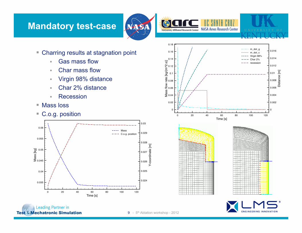
§ Charring results at stagnation point § Gas mass flow § Char mass flow § Virgin 98% distance § Char 2% distance § Recession
§ Mass loss § C.o.g. position
Mandatory test-case
0 20 40 60 80 100 120Time [s]
0
0.02
0.04
0.06
0.08
0.1
0.12
0.14
0.16
0.18
Mas
s flo
w ra
te [k
g/(m
^2.s
)]
0
0.002
0.004
0.006
0.008
0.01
0.012
0.014
0.016
Dis
tanc
e [m
]
m_dot_gm_dot_cVirgin 98%Char 2%recession
0 20 40 60 80 100 120Time [s]
0.035
0.04
0.045
0.05
0.055
0.06
Mas
s [k
g]
0.024
0.025
0.026
0.027
0.028
0.029
0.03
Y-co
ordi
nate
[m]
MassC.o.g. position

10 - 5th Ablation workshop - 2012
§ Modification of the basic case § 3.2: Orthotropic conductivity (axis-symmetric/3D)
• Define the values α1 and α2
• TTT-direction along the axis of axis-symmetry
§ 3.3 Orthotropic conductivity with 3D heat flux (3D) • 3D heat flux to test 3D behavior
• Replaced by à § Orthotropic material with TTT non-aligned with axis of axis-symmetry
§ Other ideas are welcome …
Mandatory test-case
isotropicIP
TTT λα
α
λ
λ
2
1
00
00=
( )( ) ( )[ ]22
221
1,yx yx
eyxf−+−−
+=µµ
σβ

11 - 5th Ablation workshop - 2012
§ Small entry probe (SPRITE) test-case proposal § Questions that need to be answered:
§ Will we apply a realistic re-entry load, and if so who will be capable and willing to supply this?
§ How will the geometry of the test-case be defined:
• will a 2D (cross section) description be given?
• will a full 3D CAD model be supplied? • will a finite element mesh be supplied?
§ What are the results we would like to obtain? § Do we need to model radiation heat
exchange (between structure and instruments) inside the capsule?
§ Which of the participants is able and willing to do this test?
Re-entry probe case
Figure 2 - SPRITE Probe Cross-section and
Instrumentation
Due to the limited budget for this project some compromises had to be made that deviated from the flight-like aspects desired, however the overall design used flight proven TPS (PICA and Shuttle tile) and the above mentioned MEDLI instrumentation. Figure 2 shows a cross-section of the probe and location of the instrumentation. Details of the probe design, construction and testing are detailed below. 5. PR O B E D ESI G N The development effort for the SPRITE probe consisted of the following aspects: mechanical design and fabrication, TPS design and fabrication, data acquisition system design and fabrication, computational fluid dynamics (CFD) analyses, thermal analysis and thermal-structural analysis. 5.1 M echanical Design Both the thermal protection system and the underlying structure needed to be designed for the SPRITE probe. From previous tests (see [1]) of wooden models it was know that a diameter of 35.6 cm (14.0 inches) would work for the arc heater configuration desired. This requirement and the desire to maximize the internal volume of the probe shaped the rest of the design. For the TPS the first exercise was the choice of materials. In a real mission design reentry requirements, size, weight and other parameters would be used to choose the TPS material, for SPRITE the choice was made by what materials were easily available. This led to the choice of PICA (Phenolic Impregnated Carbon Ablator) as the forebody TPS material and Space Shuttle tile for the afterbody. In
order to maximize the interior volume of the probe the thickness of the TPS was limited to 2.5 cm (1 inch) which meant the TPS thickness was dictated by the desired probe volume rather than sizing for a particular reentry or arc-jet condition, i.e., PICA was not sized to meet a bondline temperature constraint. Given the constraints to the design a very a robust and workable concept emerged. Once the TPS was chosen the structure of the probe body, to which the TPS was attached and which contained the internal data acquisition system, was designed. Again cost and availability played a large role in the choices made. Composites, Titanium and spin-formed Aluminum were all briefly considered but in the end traditional CNC (computer numeric controlled) lathe machining from thick billets of 6061-T651 Machined Aluminum was determined to be the least expensive and shortest lead-time method available. Figure 3 shows the three main Aluminum pieces of the probe structure the forebody, afterbody and back cover.
Figure 3 - Probe Aluminum Structure For simplicity the Aluminum fore and aft bodies were kept the same diameter at the point where they joined. This joint was also a simple butt joint fastened with cap screws from inside the probe body. In order to simplify the construction of the backshell of the probe the design was changed from hemispherical to conical. While that configuration might not be used on a flight vehicle it was deemed acceptable for a proof-of-concept arc-jet model. CFD analyses were conducted to verify the performance. Figure. 4 shows an exploded view of the probe assembly.
Empey D.M., Skokova, K.A., Agrawal P., Swanson, G.T., Prabhu D.K., Peterson, K.H. and Venkatapathy E., Small Probe Reentry Investigation for TPS Engineering (SPRITE)