Embed Size (px)
Citation preview
DEFINITION OF AN AUTOMATED VEHICLE WITH
AUTONOMOUS FAIL-SAFE REACTION BEHAVIOR TO CAPTURE
AND DEORBIT ENVISAT
Stéphane Estable(1)
, Jürgen Telaar(1)
, Max Lange(1)
, Ingo Ahrns(1)
, Katherine Pegg(1)
, Dirk Jacobsen(1)
,
Dennis Gerrits(2)
, Martijn Theybers(2)
, Luc Dayers(2)
, Simon Vanden Bussche(2)
, Stijn Ilsen(2)
, Tom
Debraekeleer(2)
, Roberto Lampariello(3)
, Marcin Wygachiewicz(4)
, Nuno Santos(5)
, Marco Canetri(5)
,
Pedro Serra(5)
, Lucia Soto Santiago(6)
, Artur Łukasik(6)
, John Ratti(7)
, Dawn Puddephatt(7)
, Richard
Rembala(7)
, Leanne Evans Brito(7)
, Michel Bondy(7)
, Robin Biesbroek(8)
, Andrew Wolahan(8)
(1) Airbus Defence & Space, Airbus-Allee 1 28199 Bremen, Germany, Email: [email protected],
[email protected], [email protected], [email protected], [email protected],
QinetiQ Space nv, Hogenakkerhoekstraat 9, 9150 Kruibeke, Belgium, Email: [email protected],
[email protected], [email protected], [email protected], [email protected],
German Aerospace Center (DLR) Münchener Straße 20 82234 Oberpfaffenhofen-Weßling, Germany,
Email: [email protected] (4)
SENER Sp. z o. o., Aleje Jerozolimskie 202, 00-001 Warszawa, Poland, Email: [email protected] (5)
GMVIS SKYSOFT S.A., Av. D. João II, Lote 1.17.02 - Torre Fernão de Magalhães, 7, 1998-025 Lisbon, Portugal,
Email: [email protected], [email protected], [email protected] (6)
GMV Innovating Solutions Sp. z o.o., Ul. Hrubieszowska 2. 01-209 Warsaw. Poland,
Email: [email protected], [email protected] (7)
MacDonald, Dettwiler and Associates Inc., 9445 Airport Road, Brampton, Ontario, Canada L6S 4J3,
Email: [email protected], [email protected],
[email protected], [email protected], [email protected] (8)
ESTEC, Keplerlaan 1, 2201 AZ Noordwijk, The Netherlands, Email: [email protected],
ABSTRACT
e.Deorbit is a compelling mission concept that aims to
address the most pressing debris challenge for Europe:
the post-life disposal of ESA’s environmental satellite
ENVISAT, which has the highest catastrophic risk-
impact of any European spacecraft. This mission is
unique in its operational complexity and challenges, and
calls for a high fidelity system.
With ESA as the customer, an Airbus DS-led industrial
team has developed the system definition to the
intermediate System Requirements Review (SRR). The
developed concept foresees the Chaser as a constrained
automated vehicle with autonomous fail-safe monitoring
and reaction behaviour functions. All activities required
to approach, synchronise, capture and fix the Target can
be performed automatically onboard, with
corresponding autonomous monitoring functions. The
autonomous monitoring functions are capable of taking
onboard decisions if constraint violations are detected to
abort the operations and to escape the surrounding of the
Target without creating debris. The major results of this
Phase B1 study on mission context, mission analysis,
safety, system properties, system architectures and
capture techniques are reported.
1 INTRODUCTION
1.1 The space debris problem
According to ESA [1] [2], today’s space debris
environment poses a hazard to the safety of operational
spacecraft in space and of people and property on Earth.
As of November 2015, more than 5100 launches had
placed some 7200 satellites into orbit, of which about
4100 remained in space. Only a small fraction - about
1100 - are still operational today. These are
accompanied by almost 2000 spent orbital rocket bodies
and a large number of fragmentation debris, caused by
the break-up of more than 200 objects, as well as
mission related objects. This large amount of space
hardware has a total mass of more than 8000 tonnes.
Since 2005, some IADC (Inter-Agency Space Debris
Coordination Committee) members have been
assessing, under a variety of space debris mitigation
scenarios [3], the stability of the LEO space object
population and the need to use active debris removal
(ADR) to stabilize the future LEO environment. ASI,
ESA, ISRO, JAXA, NASA, and UKSA [4] employed
their own environment evolution models under a
common set of initial conditions and assumptions,
Proc. 7th European Conference on Space Debris, Darmstadt, Germany, 18–21 April 2017, published by the ESA Space Debris Office
Ed. T. Flohrer & F. Schmitz, (http://spacedebris2017.sdo.esoc.esa.int, June 2017)
reaching very similar results. The study confirmed that
the current LEO object population will grow even in a
scenario with full compliance with existing national and
international space debris mitigation guidelines. To
stabilize the LEO environment, first of all, mitigation
measures need to be applied to the required level, but
also additional measures, in particular the active
removal of the more massive non-functional spacecraft
and launch vehicle stages, should be considered and
implemented in a cost-effective manner [5].
1.2 The e.Deorbit study with ENVISAT
During the e.Deorbit ADR studies carried out by ESA,
ENVISAT was used as the debris Target. This selection
was based on several criteria. ENVISAT is one of the
few ESA-owned space debris in the densely populated
near-polar region in the 600-800 km altitude band. It is
also the debris object with the highest collision risk of
all ESA objects. Its heavy mass (8 tonnes) and large size
makes it representative of the many heavy space debris
objects such as the many Zenit 2 SL-16 stages. By
targeting ENVISAT, the e.Deorbit mission will remove
the largest mass that ESA owns in orbit.
Another reason for studying ENVISAT removal is the
complex capture. This is caused by the tumbling motion
of ENVISAT, that forces the e.Deorbit Chaser to
synchronize its attitude with that of the debris in case of
a capture with a robot arm. Furthermore, the solar panel
is locked in an unfavorable position, partially blocking
the access to one of the strongest and stiffest external
points on ENVISAT: its launcher adapter ring (LAR).
The combination of its large mass, complicated capture
access, and high collision risk with debris in its current
orbit, makes ENVISAT the perfect though ambitious
Target for the first ever ADR mission, providing an
opportunity for European industry to show case their
technological capability to a global audience.
1.3 The e.Deorbit system definition
In the frame of the ESA e.Deorbit Phase B1 study led
by Airbus DS with their partners QinetiQ Space nv,
DLR-RM, SENER Sp. z o. o., GMVIS SKYSOFT S.A.,
GMV Innovating Solutions Sp. z o.o. and MacDonald,
Dettwiler and Associates Inc., the e.Deorbit mission and
the Chaser system were defined for the intermediate
System Requirements Review (SRR) based on the
analysis of
- the mission context and stakeholders,
- the mission phases and deorbiting,
- the mission risks and hazards,
- the risks mitigations,
- the system properties like capabilities,
behaviour and physical characteristics,
- the required autonomy levels,
- the main architectures like functional,
communications, GNC, physical, operational
and safety
- the Chaser design with the platform and the
payload (arm, gripper, clamp, visual-based
navigation)
- the budgets (mass, delta-V, propellant, power,
energy, data link, RF link, pointing accuracy),
- the technology development, the verification
logic and the costing, and
- the definition of the system and architecture
requirements.
This paper will present the main results obtained during
the Phase B1 study in these different topics and
endorsed by ESA at the intermediate System
Requirements Review (SRR).
2 E.DEORBIT MISSION CONTEXT
2.1 Mission objective
The e.Deorbit mission objective as stated by ESA is to
“Remove a single large ESA-owned Space Debris from
the LEO protected zone”, the single large ESA-owned
Space Debris being ENVISAT.
2.2 Overall mission context
The mission consists of a Chaser (system-of-interest)
that is launched by a medium launcher (Vega-C),
performs a rendezvous with the Target (ENVISAT),
captures it (establish a firm connection) and removes the
Target by deorbiting from the LEO protected zone. The
rendezvous and capture operations are performed in a
LEO environment and are supervised from ground.
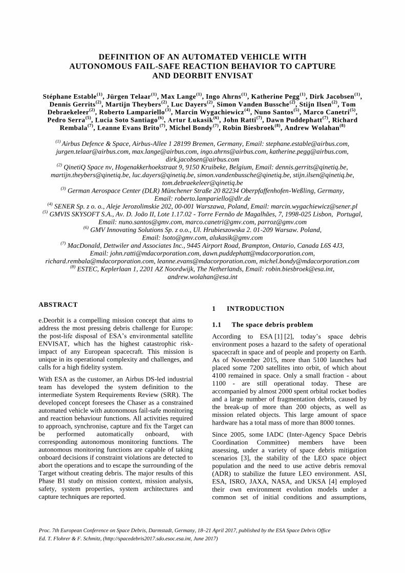
Figure 1. Mission context
The following analysis of the mission context includes
the definition of the system-of-interest and the main
stakeholders and their relationships.
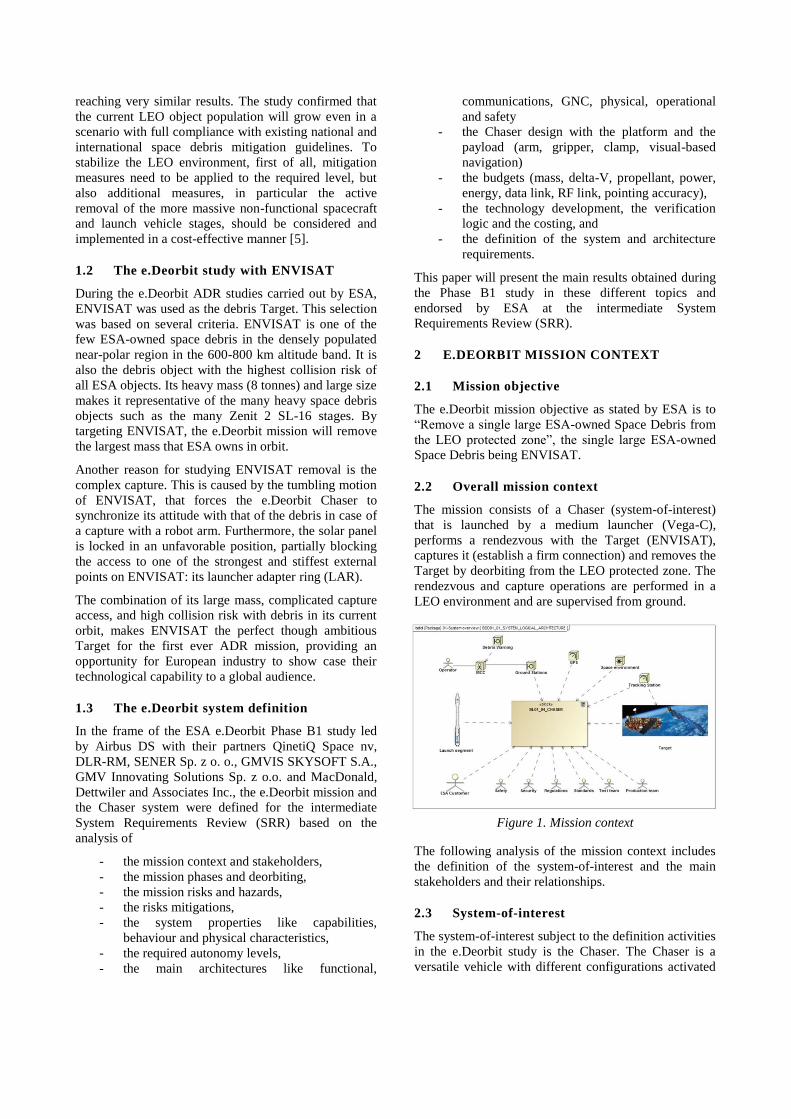
2.3 System-of-interest
The system-of-interest subject to the definition activities
in the e.Deorbit study is the Chaser. The Chaser is a
versatile vehicle with different configurations activated
according to the mission phase. It starts as a standard
satellite to perform orbit rising to the ENVISAT orbit. It
continues as an autonomous vehicle to navigate to the
close vicinity of the Target. It deploys automatically
robotic capture mechanisms to attach itself to the Target
with ground supervision. It changes to a new Stack
vehicle when firmly connected to the Target for
operating the re-entry.
Figure 2. Chaser as system-of-interest
2.4 Launcher
The nominal launcher selected by ESA for this mission
is the upgrade of the Vega launcher, named Vega-C. For
the sake of the study the reference launch mass was
1573 kg for a 300km circular injection orbit, but a
higher performance is expected (the final Vega-C
performances are still under investigation).
The backup launcher for the e.Deorbit mission is Soyuz
which has a significantly higher capability in terms of
volume and mass. So, if the Chaser is compliant with
Vega-C, it will be automatically compliant with Soyuz
in this respect.
2.5 ENVISAT
Whilst the approach to the e.Deorbit system is one of
versatility and adaptability to the state of ENVISAT
during development and on-orbit operations, it is
important that a strong effort continues on the Target
analysis, with a focus on the following aspects:
- The ENVISAT rotational dynamics: the
synchronisation to which is a key driver for the
mission. These will be characterised in an on-
ground campaign prior to launch and also on-
orbit during the Target Characterisation Phase.
For the purpose of the study a worst case rate
of 5deg/s in all axes is assumed.
- The non-passivation: especially in the case of
impact on the capture and stabilisation
dynamics and the capability of the system
(especially joints and closed-loop stabilisation
control) to account for this. Some potential
consequences may be partly characterisable on-
orbit, such as in the case where a non-natural
rotational dynamic motion of ENVISAT is
observed during the Target Characterisation
Phase, indicating on-board AOCS actuator
activity. However, not all will be apparent by
observation, such as battery residual charge. In
the case of the latter, the Chaser must be
designed to cope with worst-case scenarios for
these events.
- The interface parameters: worst-case relative
charging between the Chaser and the Target,
structural dimensions and strength for
confirmance of the gripper and clamping
mechanisms and thermal transient and
equilibrium behaviour.
Therefore, a design of the Chaser is required that is able
to deal with this kind of uncertainties in the Target
status.
2.6 Mission Control Centre
The Chaser spacecraft is an automated system with
extended supervision functions. All activities required to
approach, synchronise, capture and fix the Target can be
performed automatically onboard, with the
corresponding supervision functions. The ground
supervision functions are intended to provide
independent ground supervision and to check the Chaser
status health at the control points, which reduces the risk
of these activities. Therefore, the ground segment (data
links, ground supervision application) shall be designed
to minimise data latency, allow a high bandwidth and
maximise operator representation of the onboard
configuration from multiple sources. All operations and
trajectories are verified on-ground prior to their onboard
execution.
Another aspect is the teleoperations support for the
clamp operations. The operator shall have the ability to
prepare a list of telecommands which are then sent to
the robot for execution. This is an interactive control of
the robot from ground. This does not go as far as
telepresence, which is not foreseen in the baseline.
The ground supervision is composed of different
functions. The following functions are currently
foreseen:
- Supervision of the ‘relative’ GNC subsystem,
mainly during all phases where relative
navigation is used, with a clear focus on the
synchronised flight phase,
- Supervision of the robotic subsystem, during
the actual capture of the Target, and
- Supervision of the clamp subsystem, during the

final fixation to the Target.
These capabilities are real-time, therefore requiring a
continuous up/down-link to the spacecraft during the
time-critical phases. Only very short gaps in the link are
allowed. The current assumption is to allow maximum
time gaps of 7 seconds (which correspond to a time-to-
collision after Chaser engine cut-off during capture).
High-rate communications capabilities during critical
manoeuvres and capture phases shall be achieved with
the support of the ESTRACK ground station network.
2.7 Mission phases
The mission phases during the in-orbit operation of the
Chaser are depicted on the following picture and
summarized in the table below.
Figure 3. Mission concept
Mission Phase and Description Duration
Launch and Early Operations Phase and
Platform Commissioning (LEOP)
LEOP starts with launcher lift-off and
finishes when the Commissioning phase is
ready to be undertaken. On the injection orbit
only the platform commissioning is
performed.
1 week
Orbit Transfer and Phasing Phase
The system performs the transfer of the
Chaser from the launch orbit to the orbit of
the Target object, carrying out a phasing with
the Target object.
10 days
Rendezvous
The Chaser performs a rendezvous with the
Target object from the Entry Gate (8km
behind the target) to the Parking Hold Point
(100m behind the target).
4 days
Target characterisation
The Chaser shall perform an inspection of the
Target and evaluate the structural integrity,
attitude dynamics and CoM position.
The Rendezvous and Capture shall be
performed on battery, so previously the
12h + ground
assessment
Chaser will charge its batteries.
Synchronized Flight
Chaser synchronises its motion with
ENVISAT's rotation.
20 min
Target Capture
The Chaser performs a forced translation in
order to reduce the relative motion between
Chaser and Target to levels which are
adequate to initiate the capture operations.
The Chaser then performs a final approach to
the Capture Point (LAR in workspace of
robot arm). Capture operations are then
conducted, and upon confirmation by the
system of successful capture of the Target,
the rigidisation is performed. Upon
confirmation by the system of successful
rigidisation, the Capture Phase is completed.
5 min
Target Stabilisation
The Chaser performs the detumbling of the
Stack until the attitude envelope required for
starting the stack orbit transfer burns has
been acquired.
10 min
Coupled Flight
Slewing to power optimal attitude for battery
charging
3 h
Target Fixation
This is the phase when the Chaser is mounted
on the ENVISAT LAR with the robotic arm.
The trimming phase is to assure that the
thrust vector is well aligned on the Stack
centre of mass.
6 min +
recharge time
+ SA boom
fixation time
Stack Orbit Transfer
Once the Stack has acquired a suitable
configuration and attitude, the transfer to a
disposal orbit is undertaken.
24 hours for
orbit
determination
and recharge
time
Disposal Phase
Final burn is programmed, the burn attitude
is acquired and the burn is executed. As the
amount of propellant could be not negligible
at the end of the mission, the Chaser is
passivated.
2 h
Table 1. Mission phase description
3 CONSTRAINED AUTOMATED VEHICLE
WITH AUTONOMOUS FAIL-SAFE
REACTION BEHAVIOUR
The Chaser shall have properties that allow both safe
and cost efficient operations. The automation level
onboard the Chaser should be high to allow cost
efficient operations. The operations should also be
constrained and combined with onboard monitoring to
increase the safety. For such a complex system like

e.Deorbit with high safety requirements, the safety
properties should be considered right from the
beginning in the design process to make sure that the
functional architecture and the control structure can
effectively implement the system safety that can avoid
to the maximum extend the occurrence of accidents
leading to debris generation.
3.1 Safety-guided design [6]
Most of the time, hazard analysis is done after the major
design decisions have been made. Safety-guided design
can be used in a proactive way during the system design
by defining accident prevention as a control problem
rather than a "prevent failures" problem.
Protection against component failure accidents is well
understood in engineering with the use of redundancy
and overdesign (safety margins) to protect against
component failures. These standard design techniques
provide little or no protection against component
interaction accidents in a complex system. The added
complexity of redundancy designs can even increase the
occurrence of these accidents.
After the hazards and system-level safety requirements
and constraints have been identified, the safety-guided
design starts:
1. Try to eliminate the hazards from the
conceptual design
2. If any of the hazards cannot be eliminated, then
identify the potential for their control at system
level.
3. Create a system control structure and assign
responsibilities for enforcing safety constraints.
4. Refine the constraints and design in parallel:
a. Identify potential hazardous control actions
by each of system components that would
violate system design constraints. Restate
the identified hazard control actions as
component design constraints.
b. Determine what factors could lead to a
violation of the safety constraints.
c. Augment the basic design to eliminate or
control potentially unsafe control actions
and behaviours.
d. Iterate over the process on the new
augmented design and continue to refine the
design until all hazardous scenarios are
eliminated, mitigated or controlled.
The highest precedence is to eliminate the hazard. If the
hazard cannot be eliminated, then its likelihood of
occurrence should be reduced, the likelihood of it
leading to an accident should be reduced and, at the
lowest precedence, the design should reduce the
potential damage incurred. The higher the precedence
level, the more effective and less costly will be the
safety design effort.
Figure 4. Basic system safety design precedence
The system approach treats safety as an emergent
property that arises when the system components
interact within an environment. Emergent properties like
safety are controlled or enforced by a set of constraints
related to the behaviour of the system components.
Accidents results from interactions among components
that violate these constraints (or from a lack of
appropriate constraints on the interactions). Component
interaction accidents, as well as component failure
accidents, can be explained using these concepts.
In this framework, understanding why an accident
occurred requires determining why the control was
ineffective. Preventing future accidents requires shifting
from a focus on preventing failures to the broader goal
of designing and implementing controls that will
enforce the necessary constraints. Three basic constructs
underlie the proposed method: safety constraints,
hierarchical safety control structure and process models.
3.2 Elimination of hazards
The e.Deorbit mission and especially the rendezvous
and capture rely on well-known conditions:
- The environment is known: Orbit, dynamic,
light conditions. Due to the ENVISAT
tumbling the direction to the sun of the Chaser
is not constant but deterministic and
predictable, after the Target characterization.
- The Target behaviour is known with high
accuracy, when the Chaser is in front of the
Target and the Target characterisation has been
performed.
- The object geometries are known: the Chaser
with its appendices like the arm is fully known.
The ENVISAT Target is known and the status
will be updated once the Chaser is in orbit.
Nevertheless, uncertainties on the ENVISAT
status exist, as describe previously.
- The trajectories are known, i.e. the relative
pose between Chaser and Target is known after
the Target characterization. All trajectories
from the launch to the capture point are
prepared and verified on ground. Even if some
trajectories are generated onboard, they shall
be first validated on ground prior to their
execution. The determination of the movement
of the gripper can also be seen as a form of
navigation. In this case too, all the trajectories
of the gripper are defined in advanced and are
validated on ground in simulation w.r.t.
collision, arm configuration and reachability of
Target points.
- The system modes are known: The order of
operations to approach and capture the Target
is fully defined and deterministic.
- The communication to ground is predictable,
including the potential communication
blockages due to interferences with the Target.
All these knowns shall be integrated in the system
design to eliminate the corresponding hazards. For
instance, there is actually no need for onboard mission
planning. Uncertainties can be resolved in time flexible
hold points at safe distance. Like in factory automation,
the activity program (in e.Deorbit for rendezvous and
capture) is given by the operator and must be followed
by the machine. Along the program, the Chaser onboard
processing shall adapt its behaviour to small variations
due to the environment uncertainties and the Target
behaviour. The Chaser is just performing mission
execution of a program which is constrained by
trajectories and relative poses known in advance at each
time step. This is the automation part. One advantage of
an automated system is the possible deterministic
verification of the single functions which operate in
predefined conditions and the known transitions
between the system modes.
3.3 Control approach of safety constraints
For the hazards that cannot be eliminated, the system
architecture needs to implement functions which
guarantee a safe reaction of the Chaser in failure cases.
The safety control functions can be defined at following
levels:
- Onboard monitoring: The Chaser shall be able
to permanently check its system health status
and dynamical state (relative pose to Target,
speed, rate, internal status) w.r.t. the reference
program active for the mission phase. In case
of violation of the program constraints the
Chaser has to interrupt or abort the current
operations. This can mean to stop an approach
manoeuvre, to retreat the robot arm or to
perform a CAM (Collision Avoidance
Manoeuvre). The reaction in failure case is also
part of the program. One important part of the
system verification will be therefore to
automatically test the failure conditions and the
Chaser reaction to the maximum extend. The
escape trajectories for the platform (CAM) and
the robot arm (retreat) are generated onboard at
each cycle based on the object geometries and
the current relative pose.
- Ground monitoring: At check points, before the
Chaser enters a new mission phase, the system
shall be checked on ground. At Parking Hold
Point the platform navigation data with the
LIDAR are checked (the onboard system has
no reference data to judge whether the
computed Target pose is correct) by an
operator. This typically is a
plausibility/consistency check rather than a
performance check. After the positive ground
check, the operator sends a GO command to
the Chaser to release the next mission phase,
which is then executed automatically onboard
and monitored onboard based on the
constraints defined for this mission phase. The
operator needs to see what the Chaser sees and
measures to understand the Chaser dynamic
state. Additionally, the operator independently
assesses the remote situation with the raw
sensor data camera and LIDAR, augmented by
visualisation and simulation.
- The CAM delta-V's and the robot arm retreat
trajectory are generated onboard. The CAM
delta-V calculation is deterministic and is
therefore performed fully onboard. The robot
arm retreat trajectory is interpolated between
pre-planned trajectories in joint space which
have been generated on ground. This
mechanism is to assure that the Chaser will
react properly in a contingency case. The CAM
and robot arm retreat are triggered and
executed on-board without ground interaction
if a contingency case is detected.
- Failure corrections on ground: Without in-orbit
validation and qualification of the system
during the first flight, it is expected that some
failures may occur during onboard initialisation
procedures. This concerns mainly the
initialisation of the image processing for the
navigation of the platform (visual based
navigation) and the robot arm (visual
servoing). Some consistency checks shall be
done onboard with the expected pose, but real
accurate reference data are not available for
such uncooperative Targets. In such cases, it
shall be possible with operator interaction on
ground to correct the onboard visual navigation
data and to send back this information to the

Chaser to start the tracking with the correct
initial object pose.
- Tele-operation: All operations can be
performed automatically onboard, from the
proximity navigation to the grappling, to the
stabilisation, to the clamping and finally the
deorbiting. To continue the mission in case of
malfunction of the robotic subsystem, the
system shall be able to command manually the
robot arm from ground in a tele-operation
mode. In tele-operation mode the operator
prepares increments of the robot movement
sent to the onboard robot control system for
execution. The increments are repeated until
the desired position of the gripper is reached.
The tele-operation therefore does not put high
requirements on the communications to ground
as low bandwidth and high latency are
acceptable and the jitter does not matter (tele-
operation should not be confused with tele-
presence, which is a close-loop direct control
of the robot arm from ground with force
feedback).
- Ground mission preparation and validation: In
the selected approach, the nominal operations
and trajectories are prepared on ground to the
maximum extend. Trajectories generated
onboard like between the Rendezvous Entry
Gate and the Safe Hold Point (spiral approach
nevertheless not critical as passive safe), and
the CAM and arm retreat trajectories shall be
monitored and verified continuously on
ground. All trajectories shall be verified w.r.t.
collisions, configuration and reachability.
Basically, the logical approach for the platform
navigation and arm / gripper navigation is
identical regarding the generation and
validation process.
3.4 Constrained automated vehicle
The consequence of the selected safety approach is that
the proposed concept will not lead to an autonomous
Chaser, as during the operations, there are no onboard
decisions on the planning of the nominal operations, but
only decisions to abort the operations based on defined
constraints. The Chaser disposes of onboard program
execution and monitoring and not of onboard autonomy
for nominal operations.
The main motivation is to increase the system safety and
reliability to the required level by eliminating hazards
while discarding full autonomy in the system, and
focusing on control with ground mission preparation
and onboard monitoring. An operation can only take
place if all the conditions are fulfilled at the start of this
operation. For each operational phase, limits are defined
with margins. The limits are the constraints on the
system for each type of operation.
The selected concept to achieve a high mission safety
combined with a high automation level and ground
supervision relies therefore on a "Constrained
Automated Vehicle with Autonomous fail-safe
Monitoring and Reaction Behaviour". This means that
1. the Chaser can only execute automatically
onboard mission timelines prepared and
verified on ground, applying small corrections
based on onboard sensor data to adapt its
behaviour to changes in the environment and
Target dynamic not modelled in detail in the
simulators. The Chaser has no onboard mission
planning. This guarantees full control on the
Chaser behaviour and also on its verification.
2. the Chaser has an independent onboard
monitoring chain to observe its own behaviour
with sensors independent from the nominal
chain and compare the states to predefined
safety constraints. In case of constraint
violation, the FDIR takes the foreseen actions
like a CAM.
4 MAIN SYSTEM PROPERTIES
REQUIRED TO CAPTURE ENVISAT
The main properties necessary for the Chaser to safely
capture and deorbit ENVISAT are derived from the
analysis of the mission context, system-of-interest,
mission phases, mission characteristics, risks and safety.
The system architectures presented in chapter 5 have
been selected for generating these required properties.
4.1 Chaser capabilities
The core capabilities of the Chaser needed to implement
the mission rendezvous and capture activities are:
- Station keeping at Rendezvous entry gate
(GNC)
- Approach the Target in homing and close range
(GNC)
- Capture the Target (GNC + Robotic)
- Stabilize the Target (GNC)
- Attach the Chaser to the Target (GNC +
Robotic)
- Control the attitude of the stack (GNC)
- Monitor onboard the approach and capture for
safety
- Support bus functions to sustain the operations
The more general capabilities w.r.t. hardware and
software delivering the previously defined core
capabilities are following:
- The hardware has to survive the launch and to
deliver the functions in the space environment
of the different mission modes.
- The software controls the functional chains of
the Chaser in the different mission modes for
allowing an automatic and safe behaviour.
- Hardware and software are delivering
performances in terms of Chaser position,
attitude, velocity, rate, accuracy, and
communications, power, thermal control.
- Hardware and software are monitoring the
Chaser health status and safety constraints to
detect failures and react automatically to assure
a fail-safe behaviour, i.e. to avoid collision
with the Target and the generation of debris.
- The software manages the mission by selecting
the prepared and validated mission program
according to the mission mode and interacting
with the operators as planned (for example wait
for GO command at the hold points).
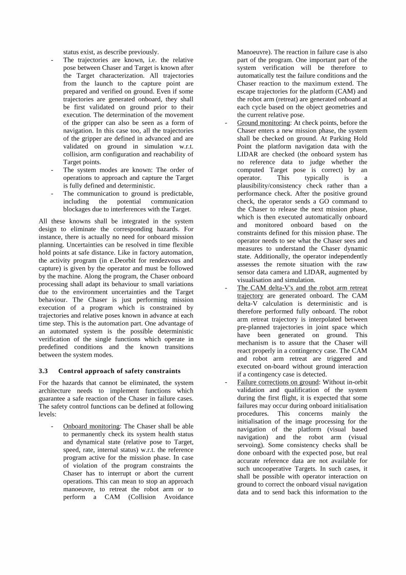
The identified top-level Chaser capabilities for the
e.Deorbit mission are represented on the diagram below.
Figure 5. Top-level Chaser capabilities for the
e.Deorbit mission
4.2 Chaser behaviour
The Chaser behaviour is characterized by mission
phases, Chaser states and Chaser modes as defined in
[7].
The system behaviour is defined first with the overall
system states: in-validation, in-transport, in-prelaunch,
in-launch, in-operation, in-disposal. Then, for each
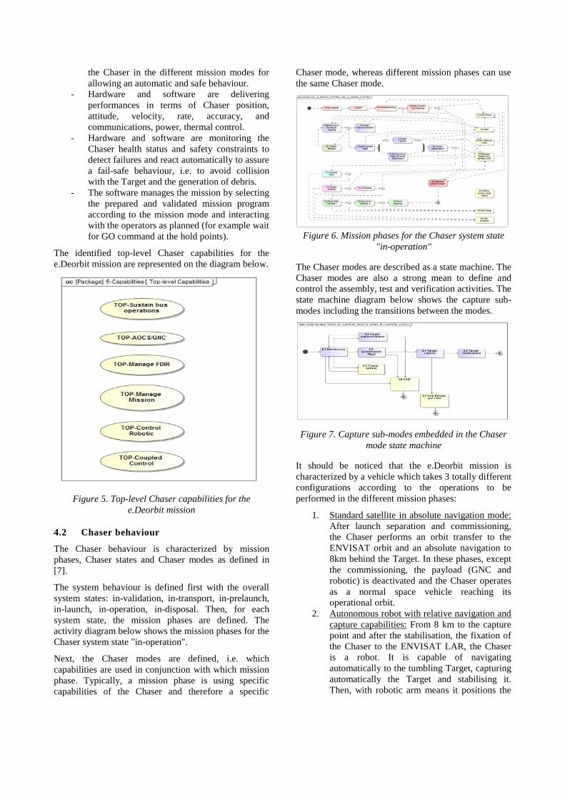
system state, the mission phases are defined. The
activity diagram below shows the mission phases for the
Chaser system state "in-operation".
Next, the Chaser modes are defined, i.e. which
capabilities are used in conjunction with which mission
phase. Typically, a mission phase is using specific
capabilities of the Chaser and therefore a specific
Chaser mode, whereas different mission phases can use
the same Chaser mode.
Figure 6. Mission phases for the Chaser system state
"in-operation"
The Chaser modes are described as a state machine. The
Chaser modes are also a strong mean to define and
control the assembly, test and verification activities. The
state machine diagram below shows the capture sub-
modes including the transitions between the modes.
Figure 7. Capture sub-modes embedded in the Chaser
mode state machine
It should be noticed that the e.Deorbit mission is
characterized by a vehicle which takes 3 totally different
configurations according to the operations to be
performed in the different mission phases:
1. Standard satellite in absolute navigation mode:
After launch separation and commissioning,
the Chaser performs an orbit transfer to the
ENVISAT orbit and an absolute navigation to
8km behind the Target. In these phases, except
the commissioning, the payload (GNC and
robotic) is deactivated and the Chaser operates
as a normal space vehicle reaching its
operational orbit.
2. Autonomous robot with relative navigation and
capture capabilities: From 8 km to the capture
point and after the stabilisation, the fixation of
the Chaser to the ENVISAT LAR, the Chaser
is a robot. It is capable of navigating
automatically to the tumbling Target, capturing
automatically the Target and stabilising it.
Then, with robotic arm means it positions the

clamp on the Target LAR for establishing the
required firm connection.
3. Stack as new space vehicle: As soon as the
Chaser is firmly attached to the Target, a new
space vehicle has been assembled in orbit
which should not separate again for the
remaining of the mission. It can perform
automatically with ground support the orbit
transfer and the disposal.
Finally, the observable and measureable Operational,
Dynamic and Physical States are defined. The
Operational States are stored in the Chaser vehicle
database which indicates the equipment duty cycles for
power and data. The Dynamic States are mainly
provided by the GNC architecture generating the GNC
states according to the flight phase (e.g. absolute
navigation, relative navigation, coupled-control with
Chaser platform and robot arm, Stack stabilisation,
Stack deorbiting). The Physical States on the Chaser
configurations are as well defined in the Chaser vehicle
database.
The full behaviour of the Chaser has been described in
SysML state machines and activity diagrams which can
be as well simulated to validate the system behaviour
definition [8] and [9].
4.3 Autonomy levels
The Chaser in its various modes covers indeed all ECSS
autonomy levels according to ECSS-E-ST-70-11C:
- E1 - Mission execution ground control; limited
on-board capability for safety issues: Covered
by the tele-operation during clamping.
- E2 - Execution of pre-planned, ground defined,
mission operations on-board: Covered by all
nominal mission phases where all operation
timelines are prepared and verified on ground
prior to onboard execution.
- E3 - Execution of adaptive mission operations
on-board: Covered by the onboard definition
and execution of CAMs and arm retreats.
- E4 - Execution of goal-oriented mission
operations on-board: Covered by the onboard
autonomous decision when to apply a mission
abort to avoid a collision (Goal-oriented
mission re-planning).
4.4 Physical properties
As typical for satellites, the main physical properties are
on the mass and the volume. Based on the study results,
the targeted mass sharing is as follows:
- Targeted Chaser wet mass: 1573 kg for a
300km circular injection orbit, coming from
the currently known Vega-C launcher
performances (the launcher mass may be
increased in the next release of the Vega-C
performances).
- Targeted total propellant mass: 798 kg
including all ECSS margins on the different
mission phases.
- Targeted Chaser dry mass: 775 kg including
20% system margin.
The maximum Chaser volume of 2216mm in diameter
and 3180mm in height is given by the Vega-C fairing.
Constraints on the material properties of the Chaser are
related to the Space debris mitigation requirements [5].
Main impacted equipment like the tanks and the
batteries are COTS equipment compatible with these
requirements.
The accelerations to be applied on the Chaser to
implement the selected rendezvous trajectories are other
physical properties to be considered. According to the
results of the GNC analyses, a max acceleration of
0,037 m/s2 is required in each direction during
rendezvous and capture.
4.5 Chaser / Arm dynamic properties
The major challenges in the close range navigation are
the motion synchronisation between Chaser and Target
and the coupled control during capture employing the
robotic arm. During the coupled control phase, the
Chaser performs station keeping at the so-called Capture
Point which is a point relative to the Target in the Target
body frame. Due to ENVISAT's tumbling motion the
Chaser has to follow a trajectory which is determined by
the angular rate and by the moments of inertia of the
Target. The Chaser has basically to compensate the
centrifugal forces along this trajectory. Furthermore, it
has to compensate the forces and torques from the robot
arm acting at the arm base.
The robot arm has to position the end-effector at the
launch adapter ring while compensating the station
keeping errors of the chaser platform. The end-effector
trajectory has to respect several constraints:
- The launch adapter ring must remain in view of
the end-effector camera throughout the
complete manoeuver, which implies an
inequality constraint on the orientation of the
robot end-effector.
- The robot joints shall not exceed position and
velocity limits. This also guarantees that robot
singularities are avoided.
- The end-effector velocity shall not exceed
image processing requirements.
- Collision avoidance between the robot and the
Target, and between itself and the Chaser.
The contact forces between end-effector and Target
shall be limited in order to avoid significant transfer of
energy, bouncing and impulse to the Target. Therefore,
the positioning of the end-effector is performed in
impedance control mode.
The overall performance of the coupled control in terms
of station keeping performance for the chaser and
positioning performance of the end-effector was
demonstrated in Monte Carlo simulations. The GNC
performances required for the e.Deorbit mission are
detailed in [10].
4.6 Operations
The mission is very complex from an operational point
of view. Where a typical LEO mission is mainly
focused on operations with a clear repetitive character,
the e.Deorbit mission is very sequential, with new and
complex activities following each other at a high pace.
Especially the synchronised flight, Target capture and
Target stabilisation phase are critical. The onboard
system shall be capable of performing all required
activities automatically including sophisticated FDIR.
The on-ground system shall perform real-time ground
supervision based on the raw and processed onboard
data.
The required longest period with continuous contact is
currently estimated to 19m10s, in which no gaps over 7
seconds are allowed for the ground supervision
functions.
During critical mission phases (synchronized flight,
Target capture, Target stabilization and Target fixation
phase phases), the onboard activities are fully automatic,
but ground has the authorization to abort the activity,
which in most cases will result in a CAM. These ground
supervision functions are required to be able to detect
when the operations go out of the nominally planned
boundaries. A dedicated set of flight rules (similar to
ATV docking flight rules) shall be available to the
operations team to ensure clear identification of
situations in which ground can interfere and what action
to trigger.
4.7 System safety
Safety is defined as the absence of accidents, where an
accident is an event involving an unplanned and
unacceptable loss. To increase safety, the focus should
be on eliminating or preventing hazards, not only
eliminating failures. Making all the components highly
reliable will not necessarily make the system safe.
Safety represents a system property not a component
property and must be controlled at system level, not the
component level.
As developed in chapter 3, the selected concept to
achieve a high mission safety combined with a high
automation level and ground supervision relies on a
"Constrained Automated Vehicle with Autonomous fail-
safe Monitoring and Reaction Behaviour".
5 MAIN SYSTEM ARCHITECTURES AND
PERFORMANCES
The system properties identified in the previous section
need to be translated in coherent architectures capable to
provide these properties [11]. The major architectures of
the e.Deorbit system summarized in this section have
the goal to provide a Chaser as a constrained automated
vehicle with autonomous fail-safe monitoring and
reaction behaviour functions.
5.1 Functional architecture
The process of the functional decomposition is started
from the capabilities identified in section 4.1. The
Chaser top-level functions derived from the capabilities
are shared between the platform and the payload.
- The platform functions
o BL01_01_SUSTAIN_BUS_OPERATIONS
o BL01_02_PERFORM_ GNC_BUS
o BL01_03_PERFORM_PLATFORM_FDIR
o BL01_04_MANAGE_MISSION
manage the platform bus from LEOP to the end of the
absolute navigation at the Entry Gate and during the
disposal and re-entry mission phases. These are the
mission phases where GNC-BUS for orbit and attitude
control without GNC-RVC (RendezVous and Capture)
is active, either for the Chaser alone or in the Stack
configuration after fixation.
- The payload functions:
o BL01_05_PERFORM_GNC_RVC
o BL01_06_CONTROL_ROBOTIC
o BL01_07_PERFORM_PAYLOAD_FDIR
manage the relative navigation phases from the Entry
Gate to the Capture Point, the capture phase with the
robot arm and the gripper where coupled-control is
active, the stabilisation and the fixation.
From these top-level functions the sub-levels functions
are further defined together with the ports and
connectors between the functional blocks at the same
level. This decomposition allows the definition of the
functional interfaces up to the Chaser level as depicted
on the diagram below.

Figure 8. Identification of the system interfaces from the
functional decomposition
5.2 Communications architecture
To meet the requirements of this mission, an S-band
communication system has been selected [12]. For near-
Earth missions, the default frequency band for
spacecraft operation is the S-band but due to its
popularity, bandwidth restrictions are in force in this
band. However, at 5 Mbit/s the requirements for
telemetry downlink do not necessarily push towards X-
band when using filtered OQPSK modulation, for
example. Staying in S-band guarantees the re-use of a
lot of the existing flight hardware and support from a
maximum amount of ground stations. S-band therefore
remains the preferred option for both uplink and
downlink.
5.3 GNC architecture
The Chaser is equipped with AOCS sensors, thrusters
for attitude control and orbit control, rendezvous
sensors, the robotic payload including a clamping
system. The AOCS sensors comprise IMU, star tracker,
sun sensor and GPS. The rendezvous phase requires
narrow angle camera, wide angle camera and LIDAR.
The narrow angle camera is also used as inspection
camera. The robotic payload consists of the robotic arm,
the gripper, the clamping mechanisms and the payload
computer. The clamping system is required to rigidly
attach the Chaser to the launch adapter ring of the
Target. It has a trimming device allowing the alignment
of the main engine thrust vector with the stack CoG.
The GNC functions are shared between GNC-BUS and
GNC-RVC. The GNC-BUS contains the standard
satellite AOCS functions as needed outside the
Rendezvous and Capture phase whereas the GNC-RVC
takes over the entire satellite during Rendezvous,
Capture and Stabilisation.
Figure 9. GNC architecture
The central part of the diagram summarises the
functions required on board. The payload management
function (MVM) is controlling the guidance, navigation
and control modes. It also enables and disables sensors
and actuators as needed according to the current mission
phase and system mode.
5.4 Physical architecture
The Chaser design configuration is mainly driven by the
launch mass requirement. The configuration is made as
compact as possible and uses a minimal amount of
panels to fit inside the launcher fairing and aims for a
low mass. The panel configuration is chosen such to
have an optimum load path from the payload panel, via
the sandwich panels to the launcher interface.
The general layout of the e.Deorbit Chaser
configuration is:
- Compact overall design for accommodation
inside launcher fairing aiming for low mass
- Optimum load path via sandwich panels to the
launcher interface (1194mm, standard
clampband)
- Unit accommodation on the inside of sandwich
panels in between the propellant tanks
- Upper and lower platform area used for
propellant system accommodation
o 2x 425N Main Engines
o 4x 220N Assist Thruster in the edges
of lower platform
o 24x 20N Attitude Control Thruster in
the edges of upper and lower platform
o Propellant equipment mainly on the
lower platform
- Robotic arm on the –X side of the structure box
- GNC Sensors mounted on top panel:
o Two LIDARs
o Two wide angle cameras and two
narrow angle cameras
- Clamping mechanism for attachment of the

Chaser on top of ENVISAT.
- Configuration closed by one body mounted
solar array panel on sun facing side and MLI /
radiator tent on opposite side.
- Two S-Band antennas and two GPS antennas.
- All platform electronic units are located on the
+/-Y panels in the same compartment as the
propellant tanks. The accommodation of the
platform subsystems is mainly driven by
thermal optimisation.
- Electronic units close to the tanks in order to
use their heat for warming up the propellant
(less additional heater power required).
- Electronic units mounted to side panels (+/-Y
panels) since the +X panel is too hot (directly
behind the solar panel).
- Batteries are at cold side of the spacecraft (-X
panel, anti-sun side).
Figure 10. Accommodation of the payload on the chaser
For the solar power generation, a fixed solar panel has
been selected. The dimensions are maximised, taking
into account the constraints from the launcher envelope
and the position of ENVISAT in the clamped
configuration. A fixed solar panel has advantages over a
deployable solar panel in terms of reliability, dynamic
disturbances during manoeuvres, testing and cost.
All payload units related to the capture of ENVISAT are
located on the top panel: the robotic arm, the clamp and
the visual navigation sensors (LIDAR and cameras). In
stowed configuration, the robotic arm is attached to the
–X panel using 4 Hold-down and Release Mechanisms
(HDRM).
5.5 Chaser budgets
The main Chaser budgets are summarized in this
section.
Mass budget
Table 2. Mass budget
The wet mass including all margins is about 87,5kg
above the known launch mass. It is however expected
that the payload launch mass of Vega-C will be raised to
a level compatible with the estimated Chaser wet mass.
Delta-V
A total delta-V for the mission has been estimated to
778 m/s. This corresponds to a total propellant mass of
912,8 kg.
Power budget
The power budget with margins for the power critical
phases is
- Arm rigidization: 1287 W
- Coupled flight: 557 W
- Trimming of clamp: 568 W
Data Link budget
The data link budget with 20% margin is for the
following mission phases:
- Synchronized flight: 2,824 Mbit/s
- Target capture and stabilisation: 4,052 Mbit/s
- Target fixation: 3,846 Mbit/s
RF Link budget
- Downlink high power, high bitrate – 5 Mbps:
5.4 dB margin
- Downlink low power, low bitrate – 128
ksps:11.3 dB
- Uplink – 64 ksps: 23.0 dB
GNC accuracy budget relative navigation during capture
- Relative attitude: 2 deg
- Relative angular rate: 0,5 deg/s
- Relative position: 0,05 m
- Relative velocity: 0,01 m/s
5.6 Operational architecture
The 3 key teams for this mission are: the Capture
Supervision and Control team (GNC & Robotics &
Clamp), the Flight Dynamic System (FDS) team and the
Platform operations team. The baseline is to have an
integrated approach, where these teams are all co-
located within the same location and infrastructure. It is

believed that this is vital for the operations of the
mission, especially during the most critical mission
phases (synchronized flight, target capture, target
stabilization and target fixation phase).
Although very linked, requirements for the systems to
perform platform operations on one side and the
Capture Supervision and Control on the other side are
quite different. Both systems are therefore seen separate,
but with a high degree of interaction between the two.
Both shall be under the control of the flight director.
5.7 Safety architecture
The industrial team is confident that an acceptable level
of mission risks can be reached, if a combination of
architectural decisions, as defined during the study, is
implemented.
- The Chaser relies on a high constrained
automated vehicle with autonomous fail-safe
monitoring and reaction behaviour. All
activities required to approach, synchronize,
capture, stabilize, fix and deorbit the Target
can be performed automatically onboard with
the associated monitoring functions using
independent sensors.
- The share between onboard and ground
activities that allows the maximum of mission
planning and validation on ground and ground
means to recover interactively from onboard
failures. Check points are defined at the main
transitions between the Chaser modes for
guaranteeing a complete Chaser check.
- Target’s attitude and motion are fully
characterized at the time of capture and system
updated with last information
- Reliable simulation prediction
- Robust GNC performance for proximity
operations
- Light independent sensors for Chaser and arm
navigation
- Tank selected to limit the sloshing
- Automatic Chaser operations with timeline
prepared and verified on-ground including
definition of strong safety constraints
- Ground supervision and intervention in all
critical phases and in particular during the
capture with low latency (400ms).
- A communications architecture that can avoid
during the duration of the grappling
communication blockages.
- Passive safe Chaser trajectories wherever
possible.
6 ROBOTIC-BASED CAPTURE
TECHNIQUE
One core technology selected for the e.Deorbit mission
is the robotic capture described in this section.
6.1 Robot arm
The chosen robot manipulator configuration is a 7-DoF
arm kinematics of 4.2 meters with following values for
the complete robot:
Link lengths [mm] = 256, 168, 1900, 168,
1730, 168, 350
This configuration allows the robot to grasp the Launch
Adapter Ring of ENVISAT, bring to zero the relative
velocity between the Chaser and the Target after capture
and subsequently seat the Chaser above the LAR.
The 7 joints provide a redundant kinematics for
positioning the end-effector, permitting null-space
movements to avoid workspace limits, joint singularities
and collisions during all robot operations. The DEOS
joints are designed to operate at a maximum rotational
speed of 10°/s and are position, as well as torque
controllable.
Figure 11. Robot arm configuration (top) and activation
during fixation of the clamp after capture (bottom)
This implies that the robot can be controlled in position,
impedance or force control modes, in accordance to the
best choice for each given task. The design
specifications for the joints maximum output torque
define a repeated peak torque and a momentary peak
torque, of 176 Nm and 314 Nm respectively.

Furthermore, the joint design includes a brake to apply a
maximum of 80 Nm.
6.2 Gripper
The Launch Adapter Ring Gripper will be used to
establish the first contact between the Chaser satellite
and ENVISAT via capturing the ENVISAT LAR. In
doing so, it will bear the loads while the Chaser
eliminates the residual rates between the two satellites
and docks to ENVISAT for the de-orbit. To achieve
these mission goals and remain compliant to the system
and mission requirements, the LAR Gripper
incorporates the following main features:
- A Grasping Mechanism to achieve a rigid
connection to the LAR. The grasping
mechanism is comprised of two jaw
assemblies, a trigger mechanism, a drive
assembly, and controller electronics.
- A Vision System formed of two sub-systems; a
Situational Awareness Subsystem (consisting
of an illumination source and a monochrome
camera) to support the visual monitoring of the
capture operation, and a Pose Estimation
Subsystem (consisting of laser patter
projectors, monochrome cameras, and optical
filters) to enable the determination of the pose
of the ENVISAT LAR.
- The Gripper Structure to which all sub-
assemblies are attached, and which provides
the mounting interface to the Chaser robotic
arm.
- The Thermal Control, which is responsible for
maintaining the gripper elements within their
acceptable temperature ranges, and is
comprised of multi-layer insulation, resistive
heater elements, and thermostats.
Figure 12. Overview of MDA’s patented LAR Capture
Tool
6.3 Clamping mechanisms
The Clamping mechanism provides a stiff interface link
between the Chaser and ENVISAT. It is foreseen to
carry a load of 1600N during de-orbit burns.
ENVISAT’s Launch Adapter Ring was selected as the
default interface for the clamping mechanisms as it
offers a clean interface.
The clamping mechanisms consist of the clamps with a
locking mechanism (also referred as fixing or fixation
mechanism). The Clamps assure self-alignment while
closing as well as provide direct contact surfaces
between the LAR and the mechanism. The main rotary
actuator is composed of a motor with a two stage
gearbox and an additional friction brake that is activated
in power-off conditions. The locking mechanism, based
on a system of linkages with an over-centred locked
position, contributes to and maintains a proper locking
and rigidisation of the clamps on the LAR. Furthermore,
the alignment mechanism is used in order to perform
trimming of the thrust vector with ENVISAT’s CoG.
Multiple sensors, including the stereo camera, rotary or
linear position sensors for the actuators (or rotary
joints), as well as adequate contact, proximity or force
sensors were considered to form the mechanism’s
closed loop control system. Redundancy and reliability
of the proposed clamping mechanism were central to the
overall design.
Figure 13. Overall view of the clamping mechanism as
a stiff connection between the Chaser and the Target
7 INNOVATIVE SOLUTIONS
In the course of the study, innovative solutions were
identified in the following domains:
- In-orbit characterization of the Target based on
measurements from Chaser sensors
- Navigation to uncooperative Targets in all
lighting conditions
- Synchronized flight with a tumbling Target
- Capture and stabilization of a tumbling Target

with a robot arm in compliant mode
- Gripper integrating fast soft capture and grasp
rigidization, and light-independent sensor
system for visual tracking
- Coupled-control between the Chaser platform
and the robotics
- Full automatic robotic system with optional
ground supervision
- Onboard monitoring concept for safe automatic
operations
- Definition of a robust communications concept
including onboard communications
architecture and ground station selection
- Concept of operations with onboard and on-
ground activity sharing
- Reuse of technologies for and from other on-
orbit servicing missions like the spacetug
- Implementation of a MBSE process based on
SysML and vehicle database
These innovative solutions could be first fully validated
in the e.Deorbit mission, and then further deployed in
on-orbit servicing missions like the Spacetug or
exploration missions.
8 CONCLUSION
Central to the e.Deorbit mission is the rendezvous of a
Chaser with a defunct satellite followed by its capture,
stabilisation, fixation and disposal. An important part of
the Chaser properties are related to safety for avoiding
the generation of new debris due to potential collisions
and also to mission efficiency.
The proposed approach to translate the Chaser
properties to architectures for achieving a high mission
safety, combined with a high automation level and
ground supervision, is the concept of a "Constrained
Automated Vehicle with Autonomous fail-safe
Monitoring and Reaction Behaviour". Additionally,
during the Airbus DS-led study it was shown that the
architectures and technologies selected for the system
comply with the required mission costs of 150M€ for
the phases B2/C/D/E1.
Major achievements were made on the definition of the
mission phases and activities, the architectures and their
dependencies, the system limitations w.r.t. the Target
tumbling rate, the required system performances, the
safety approach, the autonomy concept and operations,
the reuse approach for other OOS missions [13] and in
general on the system definition to implement a safe
active debris removal [11].
One limitation identified on the system performance is
the worst case tumbling rate of 5deg/s of the Target.
This pushes the propulsion and robot arm subsystem to
the limit of their performance in the actual system
configuration. As the ENVISAT tumbling rate is
expected to decrease in the coming years, it is envisaged
at ESA to relax the worst case tumbling rate to 3,5deg/s.
New technologies with an actual TRL below 6, such as
the visual based navigation (camera and image
processing), robot joint, gripper, clamping mechanisms,
monitoring software and payload computer, will also
need further technology development, as planned by
ESA for the next e.Deorbit maturation phase.
9 REFERENCES
1. e.deorbit Study Team (2015). Phase B1 of an Active
Debris Removal mission (E.DEORBIT Mission.
Phase B1). GSTP-SOW-e.Deorbit.
2. ESA’s Space Debris Office (BR-309 March 2013)
3. Space Debris, IADC Assessment Report for 2011
(IADC-12-06, April 2013)
4. Stability of the Future LEO Environment (IADC-12-
08, Rev. 1, January 2013)
5. Space sustainability. Adoption of Notice of ISO
24113: Space systems – Space debris mitigation
requirements, ESA, ECSS-U-AS-10, 10-02-2012
6. Leveson, Nancy G. (2011). Engineering a safer
world. Systems thinking applied to safety. The MIT
Press, Cambridge, Massachusetts.
7. Wasson, Charles S. (2010). System Phases, Modes,
and States. Solutions to Controversial Issues. Wasson
Strategics, LLC. http://www.wassonstrategics.com.
8. Estable, Stéphane et al. (2016), Generation of chaser
requirements and budgets for the e.Deorbit mission
applying a MBSE process. SECESA.
9. Estable, Stéphane et al. (2017), Systems Modelling
and Simulation of the ESA e.Deorbit Space Debris
Removal Mission. To be published in NAFEMS.
10. Telaar, Jürgen et al (2017). GNC architecture for the
e.Deorbit mission. To be published in the 7th
European Conference for Aeronautics and Space
Sciences.
11. Airbus DS (2016). Edeorbit Final Report Phase B1.
EDEB1-RIBRE-RP-0020-1.0_Final_Report. ESA.
12. Vanden Bussche, Simon et al (2016). Supervising
the capture of a large, tumbling satellite:
communication challenges. 7th ESA International
Workshop on TTC Systems for Space Applications.
13. Pisseloup, Aurélien et al. (2016). Airbus Defence
and Space’s vision and activities in active debris
removal and on-orbit servicing. 67th International
Astronautical Congress.
14. Airbus DS (2014). Edeorbit Final Report Phase A.
EDEORBIT-ASD-RP-0009-1.0_Final_Report. ESA.