Embed Size (px)
Citation preview

SEMAFOUR (316384) D2.1 Definition of self-management use cases
Version 1.0 Page 1 of 61
INFSO-ICT-316384 SEMAFOUR D2.1
Definition of self-management use cases Contractual Date of Delivery to the EC: February 28th, 2013 Actual Date of Delivery to the EC: March 6th, 2013 Work Package WP2 – Requirements, Use Cases and Methodologies Participants: NSN-D, ATE, EAB, iMinds, FT, TID, TNO, TUBS, NSN-DK Authors Beatriz González, Ana Sierra, Zwi Altman, Irina Balan, Sana Ben
Jemaa, Hans van den Berg, Andreas Bergström, Andreas Eisenblätter, Fredrik Gunnarsson, Sören Hahn, Ljupco Jorguseski, István Z. Kovács, Thomas Kürner, Daniela Laselva, Remco Litjens, Pradeepa Ramachandra, Dennis M. Rose, Cinzia Sartori, Bart Sas, Berna Sayrac, Lars Christoph Schmelz, Kathleen Spaey, Kostas Trichias, Yu Wang, Colin Willcock, Kristina Zetterberg
Reviewers Andreas Eisenblätter, Thomas Kürner Estimated Person Months: 17.5 Dissemination Level Public Nature Report Version 1.0 Total number of pages: 61
Abstract: The overall objective of the SEMAFOUR project is to design, develop and evaluate a unified self-management system for heterogeneous radio access networks. This unified self-management system includes next generation SON functions working across different RATs and/or across several hierarchical layers within these RATs, and an integrated SON management system which facilitates managing the heterogeneous infrastructure with its multitude of SON functions as one single network in a conflict-free manner. This deliverable is focused on the definition of use cases that contribute to the overall objective. SON function use cases considered are resource management supporting dual connectivity, dynamic spectrum allocation and interference management, automatic traffic steering, active/reconfigurable antenna systems, and features for integrated SON management that include operational SON coordination, policy enforcement, and a decision support system. These use cases and features set the baseline for the research activities within the project.
Keywords: Multi-layer, Multi-RAT, Policy Management, Self-management, SON, SON Coordination
SEMAFOUR (316384) D2.1 Definition of self-management use cases
Version 1.0 Page 2 of 61
Executive Summary The increasing operational complexity of current mobile networks results in the need of unified self-management systems. Such systems shall considerably improve the manageability of the network, provide performance and capacity gains, and reduce the network management costs. The first steps towards this self-management for mobile radio communication networks have already been taken with the standardised self-organising networks (SON) solutions in 3GPP. These solutions mostly target individual radio access technologies (RATs) and layers, but they typically lack a system-level perspective. SON enhancements are necessary for the interoperability of the existing features as well as for the new features and new deployments to be considered in 3GPP Release12. The SEMAFOUR (Self-Management for Unified Heterogeneous Radio Access Networks) project has the overall objective to design and develop a unified self-management system for heterogeneous radio access networks, comprising multiple RATs and multiple layers. The unified self-management system shall represent the complete radio environment as one single network towards the operator. A first key objective of the project is the development of multi-RAT/multi-layer SON functions that provide a closed loop for the configuration, optimisation and failure recovery of the network across different RATs and hierarchical layers. Such coordinated adaptation of radio (resource management) parameters is imperative for the global optimisation of the network performance. The second key objective is the design and development of an integrated SON management system, which interfaces between operator-defined performance objectives and the multi-RAT/multi-layer SON functions. This new management system will provide a unified view on the performance of the heterogeneous network environment and allow its efficient control and operation. It will enable operators to move their operational focus towards a higher level, which is more transparent to the peculiarities of the underlying network technologies and cellular layout. Bearing these two challenging targets in mind, the SEMAFOUR technical activities have been organised into three work packages (WPs):
• WP2: “Requirements, Use Cases and Methodologies.” In WP2, the self-management use cases for which technical solutions will be developed are defined, together with their requirements.
• WP4: “SON for Future Networks.” In this WP, SON functions for multi-layer LTE networks, for multi-RAT networks and for integrated multi-RAT, multi-layer networks will be developed.
• WP5: “Integrated SON Management.” In WP5, concepts, methods and algorithms for an integrated SON management consisting of policy transformation and supervision, operational SON coordination, and monitoring, will be developed.
In order to have a global vision of the activities to be carried out in the SEMAFOUR project, the work flow, starting from the identification of the use cases of interest in WP2, can be summarised as follows: the results of WP4 and WP5 will be evaluated by means of simulations. The reference scenarios, modelling assumptions and methodologies for performing those simulations are defined in WP2. The outcome of WP4 and WP5 will be the origin for a demonstrator to be developed in WP3 “Demonstrator.” All these WPs will provide input to the dissemination and exploitation activities in WP6 “Dissemination and Exploitation.” This project deliverable D2.1 “Definition of self-management use cases” defines the self-management use cases that will be the basis and the guidance for the work to be performed in the rest of the SEMAFOUR project. Chapter 1 of this deliverable defines the SON concept in the SEMAFOUR context, explaining the main relations among the work packages of the SEMAFOUR project as well. The idea of high-level objectives of the operator is also presented. Moreover, the selected SON and self-management use cases are briefly introduced. Finally, a structure to be followed when describing each use case identified in WP2 is detailed. Chapter 2 of this document describes the use cases identified for future networks, classified as follows: resource management supporting dual connectivity, dynamic spectrum allocation and interference management, automatic traffic steering, active/reconfigurable antenna systems.
SEMAFOUR (316384) D2.1 Definition of self-management use cases
Version 1.0 Page 3 of 61
The mobile terminal capabilities regarding dual connectivity communication should be taken into account by a resource management system, for maximising cell edge throughput, maximising capacity/quality/coverage, achieving desired resource utilisation, etc. By means of dynamic spectrum allocation and interference management, the available resources (carriers) will be adapted to the spatial and temporal requirements by autonomously assigning spectrum to base stations based on temporal and spatial usage and/or estimated load of spectrum, interference will be mitigated and the coverage, capacity and the quality of service in the network will be optimised. In order to efficiently support the variations of traffic demands with satisfactory service quality, it is important to steer traffic from more congested cells/layers/RATs to others that are better capable of supporting the QoS requirements, incorporating both 3GPP and WLAN RATs in multiple layers. Thanks to active and reconfigurable antenna systems, network capacity will be increased by splitting a cell into two cells, each identifying itself as a cell, broadcasting system information, etc. Moreover, for multi-RATs using the same antenna, any change of a common characteristic will impact all related RATs. Therefore, such characteristics need to be optimised with respect to all RATs simultaneously, considering both different characteristics of the RATs, as well as the traffic situation for each RAT. These use cases for future networks will be the starting point for WP4 and the most suitable ones will be selected to develop SON functions that improve the overall network performance and reduce the operational complexity through increased automation. Chapter 3 of this report presents the use cases for integrated SON management (SON coordination, policy enforcement and decision support system), which will be the starting point for WP5 that is responsible for developing concepts, methods and algorithms, and performing proofs of concept for an integrated SON management. SON coordination is in charge of supervising the functioning of the multitude of SON functions, to detect and resolve conflicts, system instabilities and undesired behaviour occurring due to the independent operation of individual SON functions. General network-oriented objectives shall be formulated in a simpler manner and yet capable of capturing the full width of operator strategies. In order to achieve the specified general network-oriented objectives, these need to be transformed into dedicated objectives for the SON functions and the operational SON coordination. Since the general network-oriented objectives as well as the dedicated SON function objectives can be formulated as polices, this process is referred to as policy transformation and enforcement, and represents an integral part of the integrated SON management layer. The decision support system represents the function within the self-management system that provides recommendations towards the operator about possible network deployment and enhancement actions such that the general network-oriented objectives can be met, in particular, network evolution which aims at giving advice with regard to hardware enhancements, and spectrum and technology management, which aims at giving advice with regard to selecting the optimal technology and spectrum for base stations. The decision support system provides an interface between the unified self-management and human-driven workflows such as network dimensioning, maintenance and servicing. Chapter 5 ends the document with concluding remarks.
SEMAFOUR (316384) D2.1 Definition of self-management use cases
Version 1.0 Page 4 of 61
List of Authors
Partner Name E-mail
NSN-D Cinzia Sartori Lars Christoph Schmelz Colin Willcock
[email protected] [email protected] [email protected]
ATE Andreas Eisenblätter [email protected]
EAB Andreas Bergström Fredrik Gunnarsson Pradeepa Ramachandra Yu Wang Kristina Zetterberg
[email protected] [email protected] [email protected] [email protected] [email protected]
iMinds Irina Balan Bart Sas Kathleen Spaey
[email protected] [email protected] [email protected]
FT Zwi Altman Sana Ben Jemaa Berna Sayrac
[email protected] [email protected] [email protected]
TID
Beatriz González Ana Sierra
[email protected] [email protected]
TNO Ljupco Jorguseski Remco Litjens Kostas Trichias Hans Van den Berg
[email protected] [email protected] [email protected] [email protected]
TUBS Sören Hahn Thomas Kürner Dennis M. Rose
[email protected] [email protected] [email protected]
NSN-DK István Z. Kovács Daniela Laselva
SEMAFOUR (316384) D2.1 Definition of self-management use cases
Version 1.0 Page 5 of 61
List of Acronyms and Abbreviations 2G 2nd Generation mobile wireless communication system (GSM, GPRS, EDGE) 3G 3rd Generation mobile wireless communication system (UMTS, HSPA) 3GPP 3rd Generation Partnership Project 4G 4th Generation mobile wireless communication system (LTE) AAS Active Antenna System ANDSF Access Network Discovery and Selection Function ANR Automatic Neighbour Relations AP Access Point ARFCN Absolute Radio Frequency Channel Number BCR Block Call Rate BTS Base Transceiver Station CAPEX CAPital Expenditure CB-eICIC Carrier Based eICIC CCO CIO
Coverage and Capacity Optimisation Cell Individual Offset
CM Configuration Management CoMP Cooperative Multi-Point CQI Channel Quality Indicator CRE Cell Range Extension DL DownLink DRX Discontinuous Reception DSS Decision Support System DSS-NE Decision Support System-Network Evolution DSS-STM Decision Support System - Spectrum and Technology Management DTX Discontinuous Transmission EDGE Enhanced Data rates for GSM Evolution eICIC Enhanced ICIC E-RAB E-UTRAN Radio Access Bearer ES Energy Saving E-UTRAN FFR
Evolved UTRAN Fractional Frequency Reuse
FTT File Transfer Time GERAN GSM EDGE Radio Access Network GPRS General Packet Radio Service GSM Global System for Mobile communication GTP GPRS Tunnelling Protocol HeNodeB Home eNodeB HetNet Heterogeneous Network HO HandOver HSDPA High Speed Downlink Packet Access HSPA High Speed Packet Access ICIC Inter-Cell Interference Coordination IEEE Institute of Electrical and Electronics Engineers IRAT Inter-RAT ISR Itf-N
Idle mode Signalling Reduction 3GPP Northbound Interface (for OAM)
ITU International Telecommunication Union ITU-T ITU’s Telecommunication Standardisation Sector
SEMAFOUR (316384) D2.1 Definition of self-management use cases
Version 1.0 Page 6 of 61
KPI LB
Key Performance Indicator Load Balancing
LTE Long Term Evolution LTE-A Long Term Evolution - Advanced MDT Minimisation of Drive Tests MLB Mobility Load Balancing MME MOCN MORAN
Mobility Management Entity Multi-Operator Core Network Multi-Operator Radio Access Network
MRO Mobility Robustness Optimisation MSE Mobility State Estimation NGMN Next Generation Mobile Networks OAM Operation, Administration and Maintenance OPEX OPerational EXpenditure OTDOA Observed Time Difference Of Arrival PCI Physical Cell Identity PDCCH Physical Downlink Control CHannel PDN-GW Packet Data Network Gateway PF PM PO
Paging Frame Performance Management Paging Occasion
QoS Quality of Service RAN Radio Access Network RAS Re-configurable Antenna System RAT Radio Access Technology RAU Routing Area Update RIM RAN Information Message RLF Radio Link Failure RRC Radio Resource Control RRU Remote Radio Unit RSRP Reference Signal Received Power RSRQ Reference Signal Received Quality SEMAFOUR SFR
Self-Management for Unified Heterogeneous Radio Access Networks Soft Frequency Reuse
S-GW Serving Gateway SLA Service Level Agreement SON Self-Organising Network SSID Service Set IDentifier TAU Tracking Area Update TCO Total Cost of Ownership TS TTT
Traffic Steering Time-to-Trigger
UE User Equipment UL UpLink UMTS Universal Mobile Telecommunications System UTRA UMTS Terrestrial Radio Access UTRAN Uu
UMTS Terrestrial Radio Access Network Interface connecting the Node B with the User Equipment
VS-AAS Vertical Sectorisation of AAS Wi-Fi Any WLAN product based on the IEEE 802.11 standards WLAN Wireless Local Area Network
SEMAFOUR (316384) D2.1 Definition of self-management use cases
Version 1.0 Page 7 of 61
WP Work Package X2AP X2 Application Protocol
SEMAFOUR (316384) D2.1 Definition of self-management use cases
Version 1.0 Page 8 of 61
Table of Contents 1 Introduction .................................................................................................. 9
1.1 SON in the SEMAFOUR Context ............................................................................ 9 1.2 Scope of the SEMAFOUR Project .......................................................................... 10 1.3 Operator High-Level Objectives ............................................................................. 13 1.4 Outline of SEMAFOUR Use Cases ........................................................................ 14 1.5 Structure for use case description ........................................................................... 16
2 SON Use Cases for Future Networks ....................................................... 18 2.1 Resource Management Supporting Dual Connectivity ......................................... 18 2.2 Dynamic Spectrum Allocation and Interference Management ............................. 21 2.3 Automatic Traffic Steering ..................................................................................... 24
2.3.1 Multi-layer LTE/Wi-Fi Traffic Steering ........................................................................ 24 2.3.2 Idle Mode Handling ........................................................................................................ 29 2.3.3 Tackling the Problem of High Mobility Users ............................................................... 34
2.4 Active/Reconfigurable Antenna Systems (AAS) .................................................... 38 2.4.1 Single-RAT ..................................................................................................................... 38 2.4.2 Multi-RAT ...................................................................................................................... 40 2.4.3 Multi-layer / Multi-RAT ................................................................................................. 42
3 Use Cases for Integrated SON Management ........................................... 43 3.1 SON Coordination and Management Through High-Level Operator Goals ....... 43
3.1.1 SON Operation in High Load Regime ........................................................................... 44 3.1.1.1 LTE Macro Layer Only .......................................................................................... 45 3.1.1.2 Multi-layer .............................................................................................................. 45 3.1.1.3 Multi-RAT ............................................................................................................... 46
3.1.2 RAN Sharing in LTE ...................................................................................................... 46 3.2 Policy enforcement .................................................................................................. 48 3.3 Decision Support System ......................................................................................... 50
3.3.1 Spectrum and Technology Management ........................................................................ 51 3.3.2 Network Evolution ......................................................................................................... 53 3.3.3 Resource Costs of QoS as Input for SLA Management ................................................. 55
4 Concluding Remarks .................................................................................. 58
SEMAFOUR (316384) D2.1 Definition of self-management use cases
Version 1.0 Page 9 of 61
1 Introduction Future wireless ecosystems will consist of numerous coexisting RATs with several cell layers within these RATs. These ecosystems will provide reliable, flexible, efficient and ubiquitous broadband wireless access to a wide variety of bandwidth-hungry advanced multimedia applications. Introducing more spectrum-efficient technologies such as HSPA+ and LTE is a natural evolution to provide the customers with better QoS. Concerning GSM, it is not planned to turn it off for a long time and should be taken into account as much as possible. This requirement of introducing more spectrum-efficient technologies, which will provide higher user data rates leading to improved user service, renders the networks more and more complex, and therefore, more difficult to monitor, control, configure and manage. The paradigm of SON enables autonomous operation, configuration and optimisation (in a closed control loop) of the networks. SON thereby requires a multitude of multiple RATs and multiple layers SON functions to be operational at the network and network element levels. With advanced SON functions and network management solutions, the operators would overcome the difficulties derived from the operation, the administration and the maintenance (OAM) of the current and future mobile radio networks. One of these solutions could be the unified-self management system proposed by the SEMAFOUR project. This system shall control the complete heterogeneous radio environment as one single network, improving the manageability of the network, providing performance and capacity gains, and reducing the network management costs. The first steps towards this self-management system for mobile radio communication networks have already been taken with the standardised self-organising networks (SON) solutions in 3GPP. These solutions mostly target individual radio access technologies (RATs) and layers, and are missing a system-level perspective. SON enhancements are necessary for the interoperability of the existing features as well as for the new features and new deployments to be considered in 3GPP Release 12. The unified-self management system will enable operators to move their operational focus towards a higher, more global level, which is more transparent to the peculiarities of the underlying network technologies and cellular layout. The operator shall be able to specify general network-oriented objectives that capture the desired network-wide performance in line with the operator’s strategy, which are then effectively translated to automatically, dynamically and in a unified way optimised radio networks.
1.1 SON in the SEMAFOUR Context The automation of OAM within mobile radio networks has become an increasingly important focus area for telecommunication operators. This is due to the aforementioned increasing complexity of the networks and the corresponding challenges to guarantee their operability, the need to simplify tasks for maintaining, configuring and administering their assets, and in addition to maintain the flexibility to enable the rapid deployment of new services. Self-organising networks are the means for implementing this automation. SON is a topic in research and standardisation for several years now, and first SON functions have been implemented with the introduction of LTE. The objective of the SEMAFOUR project is to widen the scope of current SON from single-RAT, single-layer functions towards functions operating across several radio access technologies, and across several layers within these RATs. Furthermore, SEMAFOUR addresses the operation of the SON system, i.e., ensuring the conflict-free execution of a multitude of SON functions by run-time coordination, but also the management of the SON system itself through policies and rules.
SEMAFOUR (316384) D2.1 Definition of self-management use cases
Version 1.0 Page 10 of 61
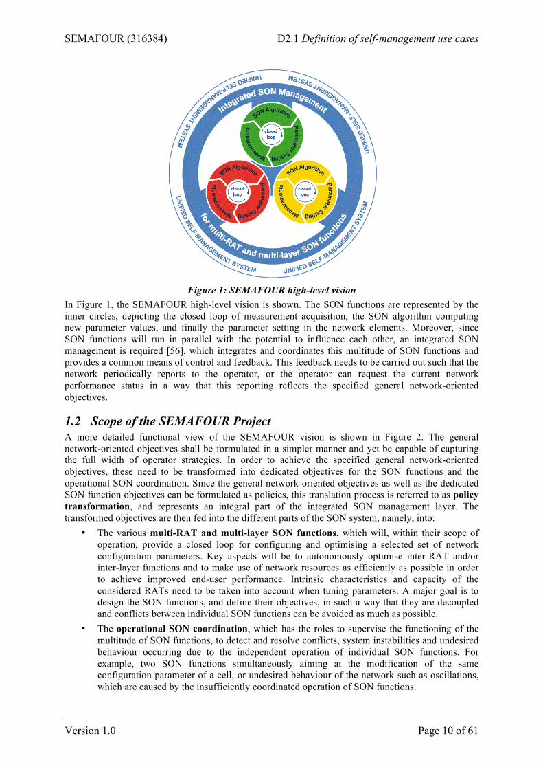
Figure 1: SEMAFOUR high-level vision
In Figure 1, the SEMAFOUR high-level vision is shown. The SON functions are represented by the inner circles, depicting the closed loop of measurement acquisition, the SON algorithm computing new parameter values, and finally the parameter setting in the network elements. Moreover, since SON functions will run in parallel with the potential to influence each other, an integrated SON management is required [56], which integrates and coordinates this multitude of SON functions and provides a common means of control and feedback. This feedback needs to be carried out such that the network periodically reports to the operator, or the operator can request the current network performance status in a way that this reporting reflects the specified general network-oriented objectives.
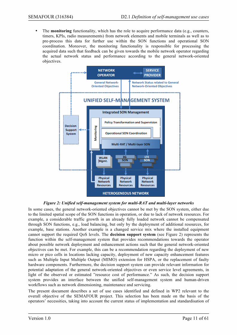
1.2 Scope of the SEMAFOUR Project A more detailed functional view of the SEMAFOUR vision is shown in Figure 2. The general network-oriented objectives shall be formulated in a simpler manner and yet be capable of capturing the full width of operator strategies. In order to achieve the specified general network-oriented objectives, these need to be transformed into dedicated objectives for the SON functions and the operational SON coordination. Since the general network-oriented objectives as well as the dedicated SON function objectives can be formulated as policies, this translation process is referred to as policy transformation, and represents an integral part of the integrated SON management layer. The transformed objectives are then fed into the different parts of the SON system, namely, into:
• The various multi-RAT and multi-layer SON functions, which will, within their scope of operation, provide a closed loop for configuring and optimising a selected set of network configuration parameters. Key aspects will be to autonomously optimise inter-RAT and/or inter-layer functions and to make use of network resources as efficiently as possible in order to achieve improved end-user performance. Intrinsic characteristics and capacity of the considered RATs need to be taken into account when tuning parameters. A major goal is to design the SON functions, and define their objectives, in such a way that they are decoupled and conflicts between individual SON functions can be avoided as much as possible.
• The operational SON coordination, which has the roles to supervise the functioning of the multitude of SON functions, to detect and resolve conflicts, system instabilities and undesired behaviour occurring due to the independent operation of individual SON functions. For example, two SON functions simultaneously aiming at the modification of the same configuration parameter of a cell, or undesired behaviour of the network such as oscillations, which are caused by the insufficiently coordinated operation of SON functions.
SEMAFOUR (316384) D2.1 Definition of self-management use cases
Version 1.0 Page 11 of 61
• The monitoring functionality, which has the role to acquire performance data (e.g., counters, timers, KPIs, radio measurements) from network elements and mobile terminals as well as to pre-process this data for further use within the SON functions and operational SON coordination. Moreover, the monitoring functionality is responsible for processing the acquired data such that feedback can be given towards the mobile network operator regarding the actual network status and performance according to the general network-oriented objectives.
Figure 2: Unified self-management system for multi-RAT and multi-layer networks
In some cases, the general network-oriented objectives cannot be met by the SON system, either due to the limited spatial scope of the SON functions in operation, or due to lack of network resources. For example, a considerable traffic growth in an already fully loaded network cannot be compensated through SON functions, e.g., load balancing, but only by the deployment of additional resources, for example, base stations. Another example is a changed service mix where the installed equipment cannot support the required QoS levels. The decision support system (see Figure 2) represents the function within the self-management system that provides recommendations towards the operator about possible network deployment and enhancement actions such that the general network-oriented objectives can be met. For example, this can be a recommendation regarding the deployment of new micro or pico cells in locations lacking capacity, deployment of new capacity enhancement features such as Multiple Input Multiple Output (MIMO) extension for HSPA, or the replacement of faulty hardware components. Furthermore, the decision support system can provide relevant information for potential adaptation of the general network-oriented objectives or even service level agreements, in light of the observed or estimated ”resource cost of performance.” As such, the decision support system provides an interface between the unified self-management system and human-driven workflows such as network dimensioning, maintenance and servicing. The present document describes a set of use cases identified and defined in WP2 relevant to the overall objective of the SEMAFOUR project. This selection has been made on the basis of the operators’ necessities, taking into account the current status of implementation and standardisation of
SEMAFOUR (316384) D2.1 Definition of self-management use cases
Version 1.0 Page 12 of 61
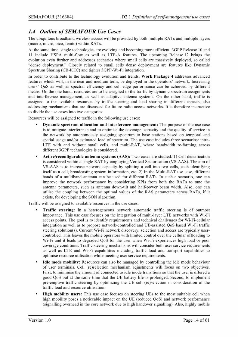
SON functions (vendors’ information, 3GPP technical specifications and reports) and the challenges imposed by a complex network deployment with multiple RATs, layers and evolved radio network concepts. The selected use cases are listed in the following bullets:
• Use cases for heterogeneous networks o Resource management supporting dual connectivity o Dynamic spectrum allocation and interference management o Automatic traffic steering
§ Multi-layer LTE/Wi-Fi traffic steering § Idle mode mobility handling § Tackling the problem of high mobility users
o Active/Reconfigurable Antenna Systems • Use cases for integrated SON management
o Policy enforcement o SON coordination and SON management through high-level operator goals
§ SON operation in high load regime § RAN sharing in LTE
o Decision Support System § Spectrum and technology management § Network evolution § Resource costs of QoS as input for SLA management
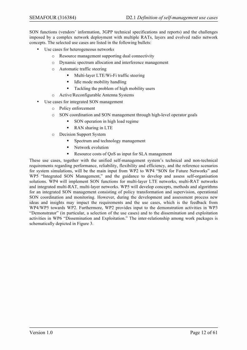
These use cases, together with the unified self-management system’s technical and non-technical requirements regarding performance, reliability, flexibility and efficiency, and the reference scenarios for system simulations, will be the main input from WP2 to WP4 “SON for Future Networks” and WP5 “Integrated SON Management,” and the guidance to develop and assess self-organisation solutions. WP4 will implement SON functions for multi-layer LTE networks, multi-RAT networks and integrated multi-RAT, multi-layer networks. WP5 will develop concepts, methods and algorithms for an integrated SON management consisting of policy transformation and supervision, operational SON coordination and monitoring. However, during the development and assessment process new ideas and insights may impact the requirements and the use cases, which is the feedback from WP4/WP5 towards WP2. Furthermore, WP2 provides input to the demonstration activities in WP3 “Demonstrator” (in particular, a selection of the use cases) and to the dissemination and exploitation activities in WP6 “Dissemination and Exploitation.” The inter-relationship among work packages is schematically depicted in Figure 3.
SEMAFOUR (316384) D2.1 Definition of self-management use cases
Version 1.0 Page 13 of 61
Figure 3: Schematic view of the overall project structure
The work in WP4 and WP5 is strongly related, as indicated in Figure 3. In particular, for the development and testing of the SON coordinator in WP5, but also for the development of the policy transformation functionality, inputs regarding the SON functions to be developed in WP4 (or already existing outside the SEMAFOUR project) are required. On the other hand, the work on the SON coordinator, the policy transformation and the monitoring functionalities of the integrated SON management leads to additional requirements on both existing and WP4 SON functions. A similar, but somewhat less intensive, two-way interaction (top-down and bottom-up) is related to the development, assessment and simulation of concepts and methods for mapping general network-oriented objectives (developed in WP5) to SON function specific policies for individual SON functions (such as those developed in WP4). Additionally, the main results of WP4 and WP5 will form the basis for the demonstrator to be developed in WP3. WP4 and WP5 will also provide input to the dissemination and exploitation activities in WP6 as well as to the standardisation activities planned in this work package.
1.3 Operator High-Level Objectives Nowadays, wireless operators face the complicated task of running their networks while introducing new services and achieving goals in terms of customer satisfaction, benefit, market share, innovation, reputation, etc. In order to manage this complexity, the wireless network operator has dedicated objectives at each level of its business organisation. At the top level, the aim is to accomplish the high-level objectives. These can be short-term (e.g., maximizing the revenues, minimizing CAPEX/OPEX), medium-term (e.g., decreasing the number of churns or "outgoing subscribers,” building a new infrastructure) and long-term (e.g., keeping its reputation as the "most Green wireless operator") objectives. At the technical operational level, individual SON functionalities aim at optimising certain KPIs such as call drop, call blocking, handover failure, coverage, capacity (typically throughput) and delay. These metrics can be of different temporal scales, layers, contexts and domains. A dynamic translation of the high-level operator objectives into low-level targets for SON functionalities facilitates the achievement of the high-level goals. This must be possible for the operator, and should be carried out automatically, with no or minimum human intervention.
SEMAFOUR (316384) D2.1 Definition of self-management use cases
Version 1.0 Page 14 of 61
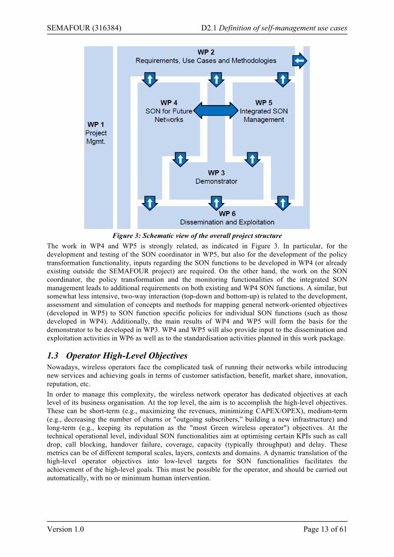
1.4 Outline of SEMAFOUR Use Cases The ubiquitous broadband wireless access will be provided by both multiple RATs and multiple layers (macro, micro, pico, femto) within RATs. At the same time, single technologies are evolving and becoming more efficient: 3GPP Release 10 and 11 include HSPA multi-flow as well as LTE-A features. The upcoming Release 12 brings the evolution even further and addresses scenarios where small cells are massively deployed, so called “dense deployment.” Closely related to small cells dense deployment are features like Dynamic Spectrum Sharing (CB-ICIC) and tighter 3GPP-Wi-Fi integration. In order to contribute to the technology evolution and trends, Work Package 4 addresses advanced features which will, in the near and medium term, be deployed in the operators’ network. Increasing users’ QoS as well as spectral efficiency and cell edge performance can be achieved by different means. On the one hand, resources are to be assigned to the traffic by dynamic spectrum assignments and interference management, as well as adaptive antenna systems. On the other hand, traffic is assigned to the available resources by traffic steering and load sharing in different aspects, also addressing mechanisms that are discussed for future radio access networks. It is therefore instructive to divide the use cases into two categories: Resources will be assigned to traffic in the following use cases:
• Dynamic spectrum allocation and interference management: The purpose of the use case is to mitigate interference and to optimise the coverage, capacity and the quality of service in the network by autonomously assigning spectrum to base stations based on temporal and spatial usage and/or estimated load of spectrum. The use case includes three scenarios: intra- LTE with and without small cells, and multi-RAT, where bandwidth re-farming across different 3GPP technologies is considered.
• Active/reconfigurable antenna systems (AAS): Two cases are studied: 1) Cell densification is considered within a single RAT by employing Vertical Sectorisation (VS-AAS). The aim of VS-AAS is to increase network capacity by splitting a cell into two cells, each identifying itself as a cell, broadcasting system information, etc. 2) In the Multi-RAT use case, different bands of a multiband antenna can be used for different RATs. In such a scenario, one can improve the network performance by considering KPIs from both the RATs to tune the antenna parameters, such as antenna down-tilt and half-power beam width. Also, one can utilise the coupling between the optimal values of the RAS parameters across RATs, if it exists, for developing the SON algorithm.
Traffic will be assigned to available resources in the use cases: • Traffic steering: In a heterogeneous network automatic traffic steering is of outmost
importance. This use case focuses on the integration of multi-layer LTE networks with Wi-Fi access points. The goal is to identify requirements and technical challenges for Wi-Fi-cellular integration as well as to propose network-controlled and UE-assisted QoS based Wi-Fi traffic steering solution(s). Current Wi-Fi network discovery, selection and access are typically user-controlled. This leaves the mobile operators with limited control over the cellular offloading to Wi-Fi and it leads to degraded QoS for the user when Wi-Fi experiences high load or poor coverage conditions. Traffic steering mechanisms will consider both user service requirements as well as LTE and Wi-Fi capabilities including traffic load and transport capabilities to optimise resource utilisation while meeting user service requirements.
• Idle mode mobility: Resources can also be managed by controlling the idle mode behaviour of user terminals. Cell (re)selection mechanism adjustments will focus on two objectives. First, to minimise the amount of connected to idle mode transitions so that the user is offered a good QoS but at the same time that the UE battery life is prolonged. Second, to implement pre-emptive traffic steering by optimizing the UE cell (re)selection in consideration of the traffic load and resource utilisation.
• High mobility users: This use case focuses on steering UEs to the most suitable cell when high mobility poses a noticeable impact on the UE (reduced QoS) and network performance (signalling overhead in the core network due to high handover signalling). Also, highly mobile
SEMAFOUR (316384) D2.1 Definition of self-management use cases
Version 1.0 Page 15 of 61
user terminals are unlikely to benefit from services provided by small cells before moving on to the next cell.
• Resource management supporting dual connectivity: A small cell enhancement that will be in focus in 3GPP Release 12 [48] is dual connectivity, where user terminals can be connected to more than one base station at the time. The implementation of dual connectivity needs to consider the quality of the backhaul, and may also include nodes operating different RATs. This use case will consider how dual connectivity can have an impact on the traffic steering strategies. It is expected to be initiated when the 3GPP Release 12 small cell enhancement studies regarding dual connectivity has matured.
The multiple RATs and the multiple layers within these RATs that form the basis for the ubiquitous radio access considerably increase the complexity of operating these networks, in particular regarding the operational complexity and accordingly the required management efforts. While introducing new SON functions relieves the operator from optimising and configuring a large number of configuration parameters at the level of network elements or cells, the optimal configuration of the SON functions themselves may cause a considerable workload for the operator. Furthermore, with a large number of simultaneously active SON functions, the probability of conflicting behaviour among these SON functions is likely to increase. The operator has therefore to ensure that these SON functions operate conflict-free. Work Package 5 therefore aims at simplifying the management of a complex radio network infrastructure. This shall be achieved by 1) introducing means to coordinate the operation of simultaneously active SON functions, and by 2) enabling the unified control of the heterogeneous network environment according to the business and technical objectives and goals of the network operator. In order to tackle these two goals, the following three use cases have been defined within WP5:
• SON coordination and management through high-level operator goals: Several SON functions (or, more precisely, instantiations of SON function algorithms) are assumed to be simultaneously active in the network, and their execution may be in conflict (w.r.t. configuration parameters to be changed) or subject to mutual influence due to the acquired network KPIs. SON coordination shall prevent from conflicts during run-time (i.e., during the execution of SON functions) by establishing means to control the execution of SON functions. These means shall also support the implementation of operator goals as provided by Policy Transformation and Enforcement. There have been identified a set of network and traffic scenarios for which SON coordination may be particularly important. Two of these identified scenarios are SON coordination for SON functions operating under a high load regime (where the performance of SON coordination w.r.t. the reaction time on conflicting behaviour is particularly important), and SON coordination for SON functions operating in a RAN sharing scenario (where the target setting coming from different operators is particularly important).
• Policy transformation and enforcement: In order to enable the unified control of a heterogeneous network infrastructure according to high-level operator business and technical objectives and goals, it is necessary to establish techniques that automatically and autonomously create policies and rules that control the functioning and behaviour of the individual, simultaneously active SON functions. For this purpose it is necessary to first derive system-wide, technology-independent policies and rules that describe the desired system behaviour, and to transform these into technology-dependent, SON function specific policies and rules. The enforcement of these technical policies has to be supervised in order to ensure that the actions resulting from their execution lead to the desired system behaviour, or allow their improvement if this is not the case.
• Decision support system: The operator’s high-level business objectives and goals may not be defined in a conflict-free way, which in turn complicates the derivation of system level policies and rules, either manually or within a policy transformation and enforcement functionality as described above. Furthermore, a completely policy-driven network and SON system is unlikely to be able to resolve all issues occurring during operation, in particular, if hardware extension, network deployment, or spectrum related issues are to be handled, since
SEMAFOUR (316384) D2.1 Definition of self-management use cases
Version 1.0 Page 16 of 61
these cannot be handled in an automated way. The decision support system aims at providing guidelines and timely suggestions towards the operator how such issues can be resolved, i.e., how the high-level objectives and goals may need to be adapted in order to be conflict-free, or what kind of network extension may be required in order to resolve coverage, capacity, or service quality related issues.
1.5 Structure for use case description In this document in particular and in SEMAFOUR project in general, a use case is understood as a research topic regarding multi-RAT and multi-layer SON functions or integrated SON management. The detailed description of the different self-management use cases is based on a common guideline. By and large the template has been filled for the different use cases. Some items are optional, since they do not apply to every use case. The template has been structured as follows:
• Objective: This item describes what the use case aims to achieve, i.e., what problem(s) does it solve, or what optimisation(s) does it provide.
• Impact Area: This is the spatial area over which the SON functionality is expected to have an influence on the related Key Performance Indicators (KPIs). Values can be given in the order of (coverage areas of) cells (in relation to the type of cells, macro, pico, etc.). This item is relevant for SON coordination/management of WP5 scenarios.
• Status in Standardisation Fora: As SON use cases are being considered in 3GPP standards, an overview of the status in 3GPP is given. For use cases considering WLAN, a reference to the IEEE standardisation status is added.
• Temporal Aspects: These aspects include several temporal parameters/characteristics of the SON functionalities/algorithms, such as: o Scheduling/triggers: It describes how often the functionality described by the use case is
triggered, for example, whether it is periodical or continuous. A use case may also be triggered by a particular event.
o Observation/monitoring time: It is the time needed for the SON algorithm to collect network information for its optimisation.
o Optimisation time: It is the time needed for the optimisation algorithm to come up with optimised parameter values/configurations. Together with the previous one, optimisation time determines parameter update/reconfiguration frequency.
o Parameter/reconfiguration enforcement time: It is the time needed to enforce the proposed changes into the network.
o Visibility delay: It is the time needed for the impacts on related KPIs to be fully observable.
o Protection time: It is the safety margin which is related to random fluctuations in the network observations.
The order of magnitude (in the order of seconds, minutes, hours, days, weeks, months, etc.) will be given for each temporal attribute listed above. These temporal parameters are particularly relevant for the choice of SON combinations/groups within WP5 scenarios.
• Input Source: A description is provided on which input information is required for the use case. The solution will use the input information, and will process it to determine appropriate parameter settings.
• Parameters to Adjust: These are the parameters that will be adjusted by the self-organisation solution.
• Actions: This will describe at a high-level what the process is for the implementation of solutions for the use case.
• Simulation Approach: Brief description of the simulation procedure established for evaluating the developed technical SON solutions.
SEMAFOUR (316384) D2.1 Definition of self-management use cases
Version 1.0 Page 17 of 61
• Expected Results: Here information will be given on how the operator will benefit from the use case, i.e., what will have improved. Very related to the identified list of parameters to be adjusted.
• Measurements/Parameters/Interfaces to be Standardised: Based on the above items, requirements for standardisation in 3GPP will be listed.
• Architectural Aspects: This will define the network architecture that is required. Particularly focus is on whether a distributed or centralised solution is preferred.
• Example (Informative Description): A specific example is given of a scenario where the use case can be applied.
• Potential Gain: The gain from the use case is estimated (general view). There are different types of gain that can result from the use cases. The three main types of gain are:
o OPEX and/or CAPEX reduction o Capacity and coverage improvement o QoS improvement
These three types are often closely related to each other. The gain described in this section will be an initial estimate, based on technical expertise, rather than detailed study. The feasibility of implementing a solution will also be taken into account.
• Related Use Cases: A list of related use cases (if any).
SEMAFOUR (316384) D2.1 Definition of self-management use cases
Version 1.0 Page 18 of 61
2 SON Use Cases for Future Networks
2.1 Resource Management Supporting Dual Connectivity The resource management supporting dual connectivity use case assumes the existence of user terminals capable of receiving/transmitting user data from/to more than one cell simultaneously. Note that 3GPP has standardised the multi-flow concept for HSDPA [19] in Release 11, and there will be a study item in 3GPP Release 12 [48] investigating higher layer aspects of small cell enhancements including dual connectivity. In LTE dual connectivity concept can be seen as an extension of the Release 10 concepts: cooperative multi-point (CoMP) transmission and carrier aggregation, which aggregate data in lower protocol layers. Alternatively, the data aggregation can be realised in higher protocol layers in order to better handle backhaul with longer latencies. Mobile terminals capable of dual connectivity are served together with mobile terminals that do not have a dual connectivity capability. A terminal’s dual connectivity capability might vary depending on the terminal class. For example, different dual connectivity terminal classes might be defined based on the maximum number of cells that might be supported in the dual connectivity communication, maximum number of frequencies within one radio access technology (RAT), maximum number of different RATs, etc. The concept of multiple transmissions from (or multiple receptions at) different cells at the eNodeB of the same information (i.e., improving robustness/coverage) or different information (i.e., improving throughput) can be categorised as follows from the SEMAFOUR project point of view:
• Single frequency cells at different eNodeBs. The different eNodeBs can be macro or small cell (“low power node”) only or a mixture of macro eNodeBs and small cells.1
• Multiple frequency cells at different eNodeBs. The different eNodeBs can be macro or low-power node only or a mixture of macro and low-power node eNodeBs.
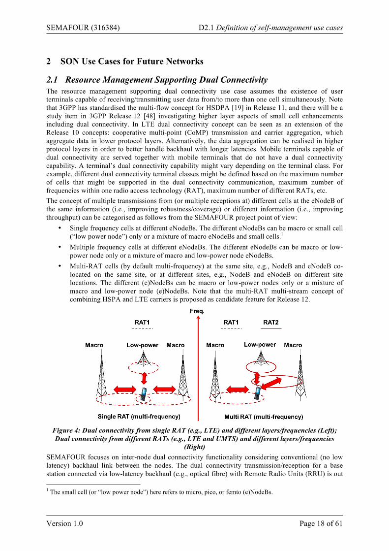
• Multi-RAT cells (by default multi-frequency) at the same site, e.g., NodeB and eNodeB co-located on the same site, or at different sites, e.g., NodeB and eNodeB on different site locations. The different (e)NodeBs can be macro or low-power nodes only or a mixture of macro and low-power node (e)NodeBs. Note that the multi-RAT multi-stream concept of combining HSPA and LTE carriers is proposed as candidate feature for Release 12.
Figure 4: Dual connectivity from single RAT (e.g., LTE) and different layers/frequencies (Left); Dual connectivity from different RATs (e.g., LTE and UMTS) and different layers/frequencies
(Right) SEMAFOUR focuses on inter-node dual connectivity functionality considering conventional (no low latency) backhaul link between the nodes. The dual connectivity transmission/reception for a base station connected via low-latency backhaul (e.g., optical fibre) with Remote Radio Units (RRU) is out 1 The small cell (or “low power node”) here refers to micro, pico, or femto (e)NodeBs.
SEMAFOUR (316384) D2.1 Definition of self-management use cases
Version 1.0 Page 19 of 61
of the scope of this use case because this has been extensively studied as CoMP and carrier aggregation. This use case is expected to consider the 3GPP Release 12 features regarding LTE dual connectivity capabilities and possibly also multi-RAT LTE and UMTS dual connectivity if there has been any discussion in 3GPP to rely to. Objective The resource management system (e.g., scheduler) and SON functions (like traffic steering, (e)ICIC, etc.) running in parallel should take into account the mobile terminal capabilities regarding dual connectivity communication and exploit these terminal capabilities in maximizing the operator defined performance targets for the overall population of the terminals, legacy and terminals supporting dual connectivity. These targets could be, e.g., maximising cell edge throughput, maximising capacity/ quality/coverage, achieving desired resource utilisation. Impact Area The whole network will be affected, i.e., in a dual connectivity enabled network due to the mobility of the dual connectivity capable terminals all cells might potentially be involved in a dual connectivity session. The HO decisions (e.g., originated from traffic steering) might be affected and for dual connectivity enabled terminals HO will transform into addition/removal/replacement of radio links. Further, interference management actions among neighbouring cells (from different nodes) operating on the same frequency might be affected considering the mix of “legacy” terminals and dual connectivity enabled terminals. Status in Standardisation Fora 3GPP has standardised multi-stream support for HSPA [19] in Release 11 enabling the network to serve a particular user in downlink via up to four cells at the same time. Additionally, 3GPP has also standardised the cooperative multi-point transmission (CoMP) for LTE in Release 10 and 11, which is also a form of dual connectivity downlink transmission towards the user by more than one cell in parallel. The CoMP feature is standardised for the case where the cells are belonging to the same eNodeB (intra eNodeB CoMP) or neighbouring eNodeBs (inter eNodeB CoMP) connected with a high-performance (i.e., low latency) backhaul. A further candidate feature discussed for studies in 3GPP is the multi-RAT dual connectivity (e.g., mixed HSPA and LTE transmission in parallel towards the user), but in Release 12 the focus will initially be on inter-eNodeB LTE dual connectivity to support less favourable backhaul (i.e., conventional backhaul link for the neighbour eNodeBs without low latency requirement). This work is part of the small cell enhancements for E-UTRAN, higher layer aspects study item [48]. Temporal Aspects Measurements have to be collected over short intervals (e.g., milliseconds to seconds during the session lifetime) to support (multiple) cell resource assignment in downlink and uplink. Input Source KPIs describing traffic levels, terminal capabilities regarding dual connectivity, coverage conditions, quality and capacity related measurements (e.g., achievable DL/UL throughput, available DL/UL resources, etc.) at all relevant cells and frequencies. Parameters to Adjust The parameters are dependent on Release 12 standardisation in 3GPP. Actions There are two phases, namely, a decision and execution phases. During the decision phase it is decided how to redistribute the resource assignment to establish dual connectivity transmission/reception at the candidate cells (at the respective (e)NodeBs). Next to the necessary coverage condition in order to add a stream to the session (i.e., the user can be served/is covered by the candidate cell) the SON function controlling the resource assignment to the dual connectivity session should consider more measurements (e.g., candidate cell load information, QoS requirements of the service, etc.) and coordinate with other (SON) functions, such as ICIC, mobility robustness optimisation, load balancing/traffic steering, in order to satisfy the pre-defined operator policy. In this way the
SEMAFOUR (316384) D2.1 Definition of self-management use cases
Version 1.0 Page 20 of 61
configuration of the dual connectivity functionality for the operator is simplified towards basic coverage thresholds. Configurations such as load thresholds, how many and which cells to include in the dual connectivity session, priorities towards other related functions are controlled by the SON function. During the execution phase the resource assignments are signalled to the cells and to the terminals. Simulation Approach The envisaged approach uses dynamic system level simulations with legacy and “dual connectivity” enabled mobile terminals. With legacy terminals it is referred to terminals that can be served by only one cell while the dual connectivity enabled terminals are capable of communicating with more than one cell in parallel. Several dual connectivity capable terminal classes will be modelled depending on the envisaged study (e.g., single frequency LTE deployment, multi-frequency LTE deployment, or multi-frequency LTE and HSPA deployment). The simulated network layout should include different (e)NodeB types such as macro and low-power nodes. The availability of load, throughput, etc., measurements among neighbouring (e)NodeBs should be modelled with the corresponding communication latency depending on the assumptions for the backhaul link between the neighbour nodes. The system under investigation should also have basic handover, ICIC, and traffic steering algorithms that are investigated and enhanced for the scenario including dual connectivity capable terminals. A step-wise approach is planned for the simulation study where the complexity of the scenario and the number of dual connectivity possibilities is gradually increased from, e.g., single frequency multi-layer (macro and low-power nodes) LTE network, multi-frequency multi-layer LTE network, and finally multi-frequency multi-RAT network including LTE and HSPA. Expected Results Higher cell edge throughput (indirectly also for “legacy” terminals), more robust mobility, more options available for the resource management and therefore effective use of the available spectrum and technologies, leading towards higher spectral efficiency. Further, due to the SON control of the dual connectivity functionality its activation does not result in excessive additional configuration and optimisation effort for the network operator (besides some necessary coverage threshold settings for adding or deleting a stream). Measurements/Parameters/Interfaces to be Standardised Inter-frequency and inter-RAT measurements, mobile terminal feedback for dual connectivity assignments, and inter-(e)NodeB signalling (especially between macro and low-power nodes) are likely candidates for standardisation. Architectural aspects Inter-(e)NodeB and inter-RAT interfaces and signalling to enable mixed assignments to “legacy” and “dual connectivity” terminals and deriving capacity/delay requirements for these interfaces. The impact on the mobile terminal from dual connectivity in terms of establishing and maintaining signalling connections and feedback reporting towards more than one cell in parallel is also relevant to be evaluated, yet it is considered as out of the scope for the SEMAFOUR project. Example (Informative Description) This use case focuses on evaluating the impact from dual connectivity enabled user terminals (when served next to “legacy terminals”) for SON functions like multi-layer and multi-RAT traffic steering and multi-layer interference management (e.g., (e)ICIC). The focus is on inter-node scenarios with conventional backhaul (i.e., without low latency requirement) and mix of legacy and dual connectivity enabled terminal capabilities that allow to split data streams across multiple links (at layer 3 or higher) that are communicated to the terminal via different cells in parallel. A step-wise approach is considered:
• First, a multi-layer (macro and low-power node) single frequency LTE network is considered where the percentage of dual connectivity enabled terminals is varied and the traffic steering and interference management SON is applied.
• Second, the system from the first step is extended with multiple LTE carriers on multiple bands having also multi-frequency dual connectivity capable terminals. Then, the multi-
SEMAFOUR (316384) D2.1 Definition of self-management use cases
Version 1.0 Page 21 of 61
frequency LTE traffic steering (and single frequency interference management) SON is applied.
• Third, the system from the second step is extended with multiple RATs (e.g., HSPA) having also multi-frequency and multi-RAT dual connectivity capable terminals. Then, the multi-frequency and multi-RAT traffic steering (and single frequency interference management) SON is applied.
Potential Gain • OPEX and/or CAPEX reduction • Capacity and cell-edge performance improvement • Mobility robustness improvements • QoS improvement
Related Use Cases The WP4 use cases “Traffic Steering” and “Dynamic Spectrum Allocation and Interference Management.” It is expected that the dual connectivity use case will be further refined after the basic concepts in these two related use cases are developed.
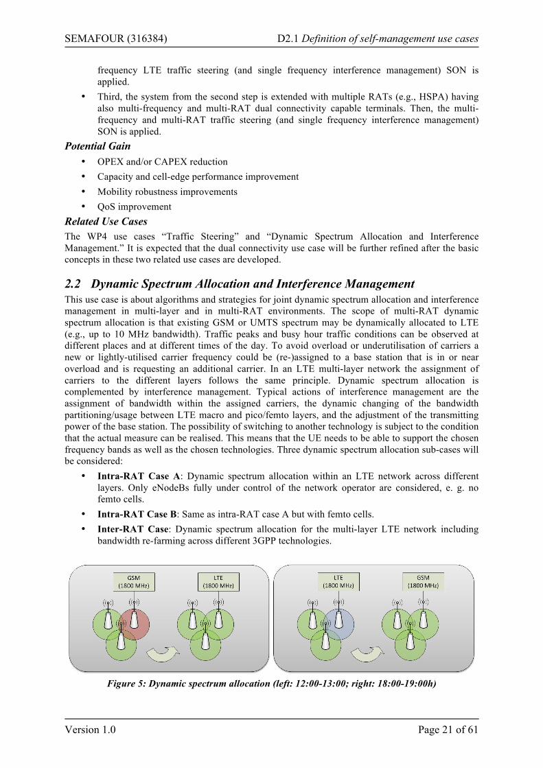
2.2 Dynamic Spectrum Allocation and Interference Management This use case is about algorithms and strategies for joint dynamic spectrum allocation and interference management in multi-layer and in multi-RAT environments. The scope of multi-RAT dynamic spectrum allocation is that existing GSM or UMTS spectrum may be dynamically allocated to LTE (e.g., up to 10 MHz bandwidth). Traffic peaks and busy hour traffic conditions can be observed at different places and at different times of the day. To avoid overload or underutilisation of carriers a new or lightly-utilised carrier frequency could be (re-)assigned to a base station that is in or near overload and is requesting an additional carrier. In an LTE multi-layer network the assignment of carriers to the different layers follows the same principle. Dynamic spectrum allocation is complemented by interference management. Typical actions of interference management are the assignment of bandwidth within the assigned carriers, the dynamic changing of the bandwidth partitioning/usage between LTE macro and pico/femto layers, and the adjustment of the transmitting power of the base station. The possibility of switching to another technology is subject to the condition that the actual measure can be realised. This means that the UE needs to be able to support the chosen frequency bands as well as the chosen technologies. Three dynamic spectrum allocation sub-cases will be considered:
• Intra-RAT Case A: Dynamic spectrum allocation within an LTE network across different layers. Only eNodeBs fully under control of the network operator are considered, e. g. no femto cells.
• Intra-RAT Case B: Same as intra-RAT case A but with femto cells. • Inter-RAT Case: Dynamic spectrum allocation for the multi-layer LTE network including
bandwidth re-farming across different 3GPP technologies.
Figure 5: Dynamic spectrum allocation (left: 12:00-13:00; right: 18:00-19:00h)
SEMAFOUR (316384) D2.1 Definition of self-management use cases
Version 1.0 Page 22 of 61
Objective The purposes of the use case “Dynamic Spectrum Allocation and Interference Management” are to adapt the available radio resources (carriers) to the spatial and temporal requirements by autonomously assigning spectrum to base stations based on temporal and spatial usage and/or estimated load of spectrum; to mitigate interference; and to optimise the coverage, capacity and the quality of service in the network. Impact Area Since dynamic spectrum allocation and interference management is important mainly in high traffic areas, the impact may be limited to those high-traffic areas and limited to the times of traffic peaks. Status in Standardisation Fora 3GPP has addressed carrier based HetNet ICIC for LTE in Release 11 with plans to continue in Release 12 [20], [21], [35], [37], [38], [39], [47]. The aim is to optimally exploit available frequency assets (carriers in the same or different bands) in heterogeneous network environments with a mixture of different BTS types and without tight synchronisation requirements. Temporal Aspects The temporal aspects have to consider several parameters/characteristics of the SON functionalities/ algorithms, such as:
• Scheduling/triggers: Periodical execution. For example, a new set of frequencies is chosen every 15 minutes based on the current situation inside the network.
• Observation/monitoring time: Continuous observation of interference, spectrum usage and traffic load to provide new sets of measures.
• Optimisation time: In the order of minutes for intra-RAT with CB-eICIC and in the order of 10x minutes for inter-RAT.
• Parameter/reconfiguration enforcement time: In the order of seconds. The changes in high load situations have to be quickly adopted in order to guarantee seamless service for the user.
• Visibility delay: In the order of minutes. • Protection time: To be defined.
Input Source Input sources include traffic load and CQI values. The sources have to be available for the whole area of network coverage. Additionally a geographical reference to the measurement reports sent by mobiles could also be useful, since the traffic peaks can vary in time and space. Minimisation of drive tests (MDT) data can be obtained by gathering user terminal reports and associating the information to some kind of localisation information to gain a better understanding of the achieved quality in different areas of the network. These technologies allow an accuracy of the geographical reference ranging from some meters to some 10s, or even 100s, of meters. Input also includes information about the cost of reconfigurations. Nodes that only can operate with one carrier needs to discontinue on-going connections before reconfiguring the operational carrier. Parameters to Adjust Parameters to adjust are the carrier frequency and its usage among different LTE layers, bandwidth and transmitting power. For intra-RAT case the possibilities for bandwidth adjustment depend on the defined component carrier bandwidths. These are unlikely to be changed “on-the-fly” due to signalling overhead. Actions The required actions are to adjust the parameters described above, i.e., to assign a new carrier frequency, bandwidth and transmitting power. The overall goal should be to maximise the achieved throughput and to avoid overload and/or no coverage at all within the network. These goals can be in conflict. Therefore an operator policy is required as an input to this use case, where the priorities in case of a conflict are defined.
SEMAFOUR (316384) D2.1 Definition of self-management use cases
Version 1.0 Page 23 of 61
Simulation Approach Some areas/cells of the network will be in overload every day at a specific time, whereas others will always have a low traffic load. To simulate such dynamic and irregular environment with different traffic loads (regarding the observation time and place), a simulation has to be realistic, dynamic and with a lot of users. To actually show the SON functions, the simulations should start with a network or a subset of a network, where overload can (already) be observed. To investigate the SON functionalities/algorithms and the impact on the network, the simulations will be divided into several simulations with different complexity.
• 1st subset (intra-RAT Case A): The assignment of carriers (per cell) will be based on spatial and temporal user distribution for an intra-RAT dynamic allocation. All cells are controlled by the operator (e.g., macro, micro, pico). The possible reuse of frequencies has to be considered in order to mitigate interference. Note that CB-eICIC [40]-[43] can be considered as baseline in this use case, as well as the CB-ICIC study phase summary [47].
• 2nd subset (intra-RAT Case B): In addition to the 1st subset, femto cells are included. These cells are not controlled by the operator, but are operated within its spectrum. This describes a greater challenge, since the positions of these cells are unknown and possible on/off behaviour is controlled only by the owner of these cells. The femto cells will be positioned only indoor. The impact of these (indoor) femto cells on the outside cells needs to be modelled. Note that autonomous CB-eICIC solutions [1]-[4], [13] can be considered in this use case.
• 3rd subset (inter-RAT Case): In this subset the inter-RAT case is considered, where spectrum is assigned across technologies. For example, in the 1800 MHz band spectrum can be assigned to GSM and/or LTE. The terminal capabilities for different RATs have to be considered and monitored to ensure plausible measures. E.g., switching from GSM to LTE makes no sense when too few terminals are able to use this technology.
For every subset the UE needs to be able to support the chosen frequency band. Also, both indoor and outdoor areas will be considered, since most of the data origins from the inside. From a network point of view, an indicator could be the network throughput, the maximum achievable data rate and the number of users, which cannot be served. The possible achievable data rate and the throughput could be important from an UE point of view. Potentially also case studies are possible that investigate which penetration rates of mobile types are required to see a significant effect by this use case. Expected Results A better use of spectrum can be achieved by reducing overload in the network and smoothing the traffic load. Also, interference should be mitigated. Measurements/Parameters/Interfaces to be Standardised An option to further improve the knowledge of the network about the geographic areas, where exactly the capacity is needed, is a geographic reference in the measurement reports sent by mobiles. A pre-condition to be able to apply this option is that the MDT feature is available both at the terminals and the network. Architectural Aspects Not clear for the moment. Whether a centralised or a decentralised solution is preferred depends on the interference relations. If possible a decentralised solution may be favourable in order to reduce signalling. Example (Informative Description) The assignment of frequencies to small cells is a basic example. In an advanced version even macro cells can be assigned frequencies based on traffic load. In one geographic area the peak time of high traffic load is different from another area. Two areas, which are close enough to interfere, may use the same carrier at different times, however. For example during day-time more capacity and hence more spectrum may be needed in a city centre, whereas parts of this spectrum can be released in the evening and assigned to suburban areas, where more capacity is needed at this time.
SEMAFOUR (316384) D2.1 Definition of self-management use cases
Version 1.0 Page 24 of 61
Potential Gain A potential gain would be an OPEX and/or CAPEX reduction relative to the delivered capacity and coverage. By the smart use of resources there is a potential that fewer sites and/or installed equipment are required, which reduces CAPEX. Since OPEX is also depending on the number of installed equipment also a gain in OPEX can be expected. Moreover, the capacity could be improved because of the smooth traffic load and of the lack of overloads within the network. This also would be accompanied by a QoS improvement. Related Use Cases Related use cases are “Automatic Traffic Steering” “Adaptive Antenna Systems,” “Radio Resource Management supporting Multiple Data Streams” and the “Decision Support System for Spectrum and Technology management.” For the latter the “Dynamic Spectrum Allocation and Interference Management Use Case” will provide input data, which indicates where the taken measures cannot improve the situation with the currently installed equipment.
2.3 Automatic Traffic Steering
2.3.1 Multi-layer LTE/Wi-Fi Traffic Steering This use case studies QoS based LTE/Wi-Fi traffic steering techniques in dense urban deployments. Such deployments are assumed to comprise outdoor LTE base stations offering macro and pico coverage and additionally indoor/outdoor Wi-Fi access points. The automatic integration and management of the available hierarchy layers, i.e., LTE macro and pico cells, and radios, i.e., LTE and Wi-Fi, are within the scope of this use case. The overall goal is to improve the end user experience and the network performance via a more efficient utilisation of Wi-Fi and cellular network assets while minimizing additional complexity. Different degrees of operator control over the Wi-Fi network and availability of Wi-Fi information at the cellular nodes will be considered.
• QoS based LTE/Wi-Fi traffic steering Network-controlled traffic steering between LTE and Wi-Fi based on information related to network loading, application, experienced QoS, UE capability, user profile, user location and user history knowledge. The objective is to provide means to the mobile operators to control the steering decisions, improving QoS while optimising the overall network performance. That is, the conditions of congested or underutilised cells / access points are limited and improved user throughput and delay statistics are achieved.
• Multi-layer aspects The solution(s) above shall include intra-LTE multi-layer traffic steering techniques to efficiently utilise the available licensed spectrum.
• Mobility aspects 3GPP Release 8 enables seamless handover between 3G and Wi-Fi [22], [23]. Because it is not certain that all devices support these feature, the solution(s) above shall work under both the assumptions of data session continuity and service interruptions when a UE moves between the LTE network and a Wi-Fi access point (AP).
The paragraphs below describe shortly the current state-of-the-art, the problem that this use case targets to solve, and in addition, provide some background information. Operators are currently exploiting offloading to (carrier/third parties) Wi-Fi networks for capacity and coverage purposes as it is inexpensive (both in terms of licensing for spectrum and for cost deployment) and may offer good network performance in high-traffic urban environments. However, nowadays Wi-Fi network discovery, selection and access are typically user-controlled via a connection manager utility installed at the client side (ad-hoc connectivity). This connection manager will likely access the user’s preferred access points whenever these are available. This leaves the mobile operators with limited control over the cellular offloading to Wi-Fi and it leads to degraded QoS for the end user when Wi-Fi experiences high load and poor coverage conditions.
SEMAFOUR (316384) D2.1 Definition of self-management use cases
Version 1.0 Page 25 of 61
On top of standardised semi-static offloading solutions, several proprietary solutions exist to enable more intelligent offloading to Wi-Fi such as NSN Smart WLAN Connectivity [15], Ericsson Network Integrated Wi-Fi (ENIW) [16], and Qualcomm’s Connectivity Engine [17]. However, the device behaviours remain diverse, uncertain and unreliable. The following assumptions are made on the network deployment, Wi-Fi device capabilities, traffic distributions, and the QoS landscape.
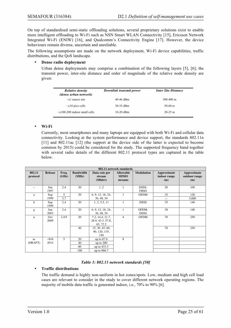
• Dense radio deployment Urban dense deployments may comprise a combination of the following layers [5], [6]; the transmit power, inter-site distance and order of magnitude of the relative node density are given:
Relative density
(dense urban network) Downlink transmit power Inter Site Distance
~x1 macro site 40-46 dBm 300-400 m
~x10 pico cells 30-35 dBm 50-60 m
~x100-200 indoor small cells 10-20 dBm 20-25 m
• Wi-Fi
Currently, most smartphones and many laptops are equipped with both Wi-Fi and cellular data connectivity. Looking at the system performance and device support, the standards 802.11n [11] and 802.11ac [12] (the support at the device side of the latter is expected to become common by 2015) could be considered for the study. The supported frequency band together with several radio details of the different 802.11 protocol types are captured in the table below.
802.11 network standards 802.11
protocol Release Freq.
(GHz) Bandwidth
(MHz) Data rate per
stream (Mbit/s)
Allowable MIMO streams
Modulation Approximate indoor range
(m)
Approximate outdoor range
(m)
— Jun 1997
2.4 20 1, 2 1 DSSS, FHSS
20 100
a Sep 1999
5 20 6, 9, 12, 18, 24, 36, 48, 54
1 OFDM 35 120 3.7 — 5,000
b Sep 1999
2.4 20 1, 2, 5.5, 11 1 DSSS 35 140
g Jun 2003
2.4 20 6, 9, 12, 18, 24, 36, 48, 54
1 OFDM, DSSS
38 140
n Oct 2009
2.4/5 20 7.2, 14.4, 21.7, 28.9, 43.3, 57.8,
65, 72.2
4 OFDM 70 250
40 15, 30, 45, 60, 90, 120, 135,
150
70 250
ac (DRAFT)
~Feb 2014
5 20 up to 87.6 8 40 up to 200 80 up to 433.3
160 up to 866.7
Table 1: 802.11 network standards [50]
• Traffic distributions The traffic demand is highly non-uniform in hot zones/spots. Low, medium and high cell load cases are relevant to consider in the study to cover different network operating regions. The majority of mobile data traffic is generated indoor, i.e., 70% to 90% [6].
SEMAFOUR (316384) D2.1 Definition of self-management use cases
Version 1.0 Page 26 of 61
• QoS/application landscape Considerable changes have occurred in recent years in the application and device landscape. For instance, the introduction of smartphones, the usage of YouTube and e-readers, pose higher demands in user expectations, for instance, in terms of how fast a website shall load or a video stream shall start playing out on any of the devices. Several QoS parameters describe the requirements in terms of the speed and reliability of data transmission posed by a certain application. The QoS support that a network is providing can then be objectively measured against those metrics. For instance, in terms of required data-rates, end-to-end delay, jitter, playback time, packet loss rate, and so on. The mapping between applications (multimedia streaming, video-based telephony, etc.) and the QoS requirements are specified independently by 3GPP, ITU-T, and IEEE.
Objective This use case targets to improve the end user experience and overall network performance. Efficient utilisation of the cellular network assets and Wi-Fi networks, avoiding conditions of congestion or under-utilisation, shall be achieved while minimizing additional network complexity. The outcome of the study may be applicable to any other small cell type i.e., not specific to Wi-Fi. The gains of the proposed algorithms will be shown against the baseline of “coverage-based LTE offload to Wi-Fi,” i.e., offload to Wi-Fi whenever available which characterises today’s Wi-Fi access. The following sub-objectives will be addressed:
• Identify requirements and technical challenges for Wi-Fi / cellular integration. • Propose network-controlled and UE-assisted QoS based Wi-Fi traffic steering solution(s).
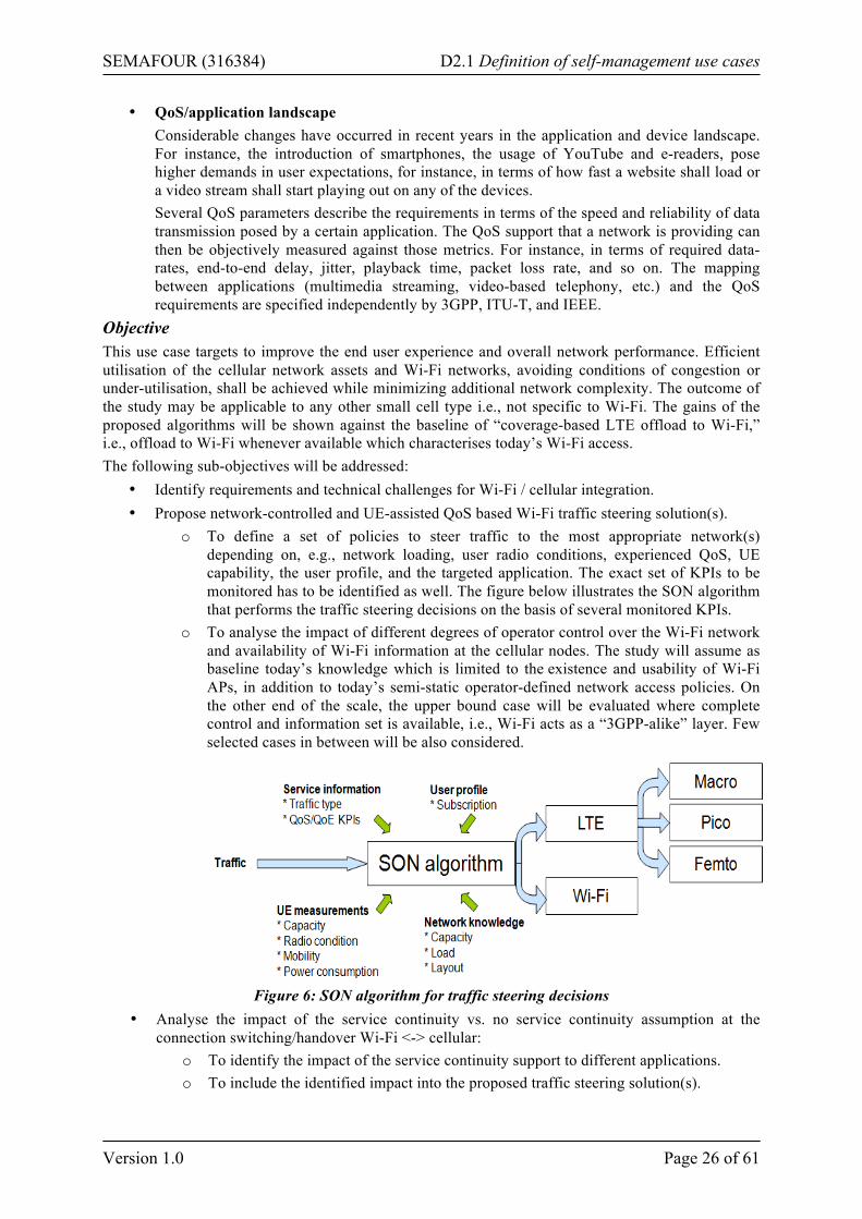
o To define a set of policies to steer traffic to the most appropriate network(s) depending on, e.g., network loading, user radio conditions, experienced QoS, UE capability, the user profile, and the targeted application. The exact set of KPIs to be monitored has to be identified as well. The figure below illustrates the SON algorithm that performs the traffic steering decisions on the basis of several monitored KPIs.
o To analyse the impact of different degrees of operator control over the Wi-Fi network and availability of Wi-Fi information at the cellular nodes. The study will assume as baseline today’s knowledge which is limited to the existence and usability of Wi-Fi APs, in addition to today’s semi-static operator-defined network access policies. On the other end of the scale, the upper bound case will be evaluated where complete control and information set is available, i.e., Wi-Fi acts as a “3GPP-alike” layer. Few selected cases in between will be also considered.
Figure 6: SON algorithm for traffic steering decisions
• Analyse the impact of the service continuity vs. no service continuity assumption at the connection switching/handover Wi-Fi <-> cellular:
o To identify the impact of the service continuity support to different applications. o To include the identified impact into the proposed traffic steering solution(s).
SEMAFOUR (316384) D2.1 Definition of self-management use cases
Version 1.0 Page 27 of 61
Impact Area The areas of the network with higher traffic densities will be affected mainly. Status in Standardisation Fora 3GPP, Wi-Fi Alliance and IEEE fora are introducing tighter coupling between Wi-Fi and the cellular network to improve the Wi-Fi usability. Particularly, functions such as node discovery and automatic authentication are seen of key importance.
• 3GPP o Standardisation of core network solutions via Access Network Discovery and
Selection Function (ANDSF) for policy enforcement [22]. o Discussion of Wi-Fi O&M northbound interface in 3GPP SA5. o 3GPP Release 12 has started a Study Item on WLAN/3GPP Radio Interworking [36]
which will investigate RAN level enhancements for WLAN interworking on top of the mechanisms already available at the Core Network (CN) level. The objectives are to improve user service, provide more operator control and better access network utilisation and reduced Operational expenditure (OPEX).
• Wi-Fi Alliance Hotspot 2.0 includes hotspot discovery and selection and easier authentication and association [51].
• IEEE o Standardisation of IEEE 802.11u which improves, first, interworking with external
networks via improved network discovery and selection and, second, QoS support via QoS map distribution [50].
o Start of the IEEE 802 Open Mobile Network Interface Range Area Network (Omni RAN) Study Group which aims at standardizing the heterogeneous networking among the IEEE 802 access technologies [49].
Temporal Aspects The temporal aspects of load sharing and balancing actions will depend on the temporal dynamics of the traffic. Actions are expected to take place in the order of several tens of seconds/minutes triggered by changes in the traffic demand in one or multiple layers. However, the exchange rate of the monitored parameters and KPIs can vary from a few hundreds of milliseconds (e.g., radio measurements) over tens of seconds (e.g., load information) to minutes (e.g., experienced QoS). Averaging of the network load, safety margins and hysteresis are expected to be required in order to avoid oscillations in the system behaviour, i.e., ping pong effects [7]. For the same reason, enforcement and observation times, the periods when any given action is enforced in the network and its outcome is observed, can be expected in the order of several tens of seconds/minutes. The trade-off between how fast the traffic steering decisions shall be taken and the cost of the decision in terms of, e.g., signalling for the layer switch, UE battery consumption to perform measurements, and service interruption, will have to be studied.
• Scheduling/triggers: Changes in the traffic demand in one or multiple layers • Observation/monitoring time: In the order of minutes • Optimisation time: In the order of tens of milliseconds • Parameter/reconfiguration enforcement time: In the order of (tens of) seconds • Visibility delay: In the order of tens of seconds/minutes • Protection time: Averaging of the network load, safety margins and hysteresis are required in
order to avoid oscillations Input Source The following aspects could be taken into consideration when designing traffic steering algorithms:
• UE/network capability
SEMAFOUR (316384) D2.1 Definition of self-management use cases
Version 1.0 Page 28 of 61
• Requested service • Subscription (golden, silver, bronze) • QoS KPIs, QoS differentiation • Cell load • Power consumption in UE and BTS • UE measurements of radio environment and interference levels such as Reference Signal
Received Power (RSRP), Reference Signal Received Quality (RSRQ), Wi-Fi scanning. • UE speed, location and mobility (stationary versus high speed) • UE history knowledge
Parameters to Adjust Traffic steering can be achieved by controlling (standardised) parameters and configurations including UE measurements, network load, refer for instance to [25]-[27]. For Wi-Fi aspects please refer to the next section. Actions Cellular networks can use (standardised) signalling messages to direct UEs to different layers and carriers in the macro layer and the same mechanisms can be used to direct traffic to different layers of small cells and macro cells [7]. Traffic steering in Wi-Fi networks is less straightforward since the Wi-Fi radio and radio configuration is not in complete control of the operator and the standardised set of Wi-Fi parameters that can be used for traffic steering are very limited [8]. The following ideas can be used to perform traffic steering between Wi-Fi and cellular networks:
• Adjust Wi-Fi admission thresholds, e.g., admissible Received Signal Strength Indicator (RSSI), the maximum number of associated clients.
• Different subscribers and devices can be configured, e.g., via the ANDSF policy, to prefer different Wi-Fi Service Set Identifications (SSID) and cellular technologies; in this way a form of traffic steering can be performed according to the Wi-Fi subscriber profiles with different SSIDs.
• Certain subscribers can be denied access based on Wi-Fi load or subscriber profile. • Operators can disable SSID announcements to avoid new devices to attach to Wi-Fi network
at a particular time-of-day or load conditions to avoid congestion. Depending on the progress of standardisation, other techniques could be assumed as well. Simulation Approach The simulations have to cover a certain geographical area of the network, a dense urban environment with outdoor LTE base stations offering macro and pico coverage as well as indoor/outdoor Wi-Fi access points. The simulations will comprise an indoor and outdoor environment, consisting of multi-floor buildings and streets. Different time and spatial variations of the traffic distribution will be considered as well as realistic UE mobility. Expected Results The extent of cellular offloading to Wi-Fi is controlled by the network and shall be used to achieve, e.g., higher throughput for UEs located at the cell edge, a higher rate of UEs to reach the minimum data rate requirements, improved network efficiency in terms of spectral efficiency (bits per Hz), and lower UE power consumption. Measurements/Parameters/Interfaces to be Standardised It is expected that several aspects of the Wi-Fi/cellular integration may require standardisation such as UE measurements and reports for access selection. Architectural Aspects Due to the dynamic nature of traffic, a distributed architecture from the cellular side is considered preferential for traffic steering schemes to fast adjust to the traffic changes. However, from a WLAN
SEMAFOUR (316384) D2.1 Definition of self-management use cases
Version 1.0 Page 29 of 61
point of view, a centralised architecture may be considered where a group of Wi-Fi access points (irrespective of their radio coverage areas) may be controlled under the cellular network. Scalability issues have to be considered. Example (Informative Description) The feasibility and performance of the proposed traffic steering algorithms will be considered in selected environments. Two examples of relevant environments are given below.
• Outdoor hot zone: A high traffic open area with surrounding cafés, restaurants and shops, characterised by a large number of people with a mixture of café/restaurant customers, pedestrians, cyclists and car riders.
• Shopping mall: A high traffic large multi-floor building with open indoor areas and small to medium size stores, characterised by a large number of people moving at low speed.
Potential Gain Gains are expected in terms of:
• Network capacity and coverage area improvement • Cell edge user throughput improvement • QoS improvement • UE power consumption reduction as compared to the baseline of coverage-based Wi-Fi
offload Related Use Cases Use cases belonging to the Automatic Traffic Steering stream as follows.
• High Mobility: The challenges of radio mobility are not in the focus of the multi-layer LTE/Wi-Fi Traffic Steering use case as they are addressed in this dedicated High Mobility use case.
• Idle Mode Mobility Handling.
2.3.2 Idle Mode Handling This use case considers the RRC_IDLE mode from two different angles:
a) The repeated transitions of users between RRC_CONNECTED and RRC_IDLE states: Due to the discontinuous nature of the user's/UE’s activity, the UE will often switch between RRC_CONNECTED - ACTIVE, RRC_CONNECTED + DRX configured and RRC_IDLE states. A great deal of control signalling (7 to 13 messages) is associated with transitions between RRC_CONNECTED and RRC_IDLE as connections to the network need to be released and subsequently re-established (Uu + S1). Such transitions are often associated with web sessions where the user downloads some information (webpage, email) and then needs some time to inspect the content before performing another action. Therefore, DRX cycle optimisation is proposed targeting a fair balance between the UE and network performance (e.g., call setup times, UE power consumption and signalling overhead in the network). A possible SON solution will take into account the state transition history (maintained by the UE) and a possible correlation between the UE service type and its traffic pattern.
b) Once in RRC_IDLE, the UE needs to find a cell to camp on in order to speed up the connection setup when new traffic is initiated or received. This use case will study traffic steering for UEs in RRC_IDLE, i.e., the network will (indirectly) instruct a UE to perform cell reselection to a more suitable cell on the same or different frequency/RAT with the objective of reducing connection setup times when traffic is initiated or received as well as the number of load based handovers after a call is established (i.e., traffic steering in RRC_IDLE and RRC_CONNECTED have to be aligned). The challenges in this case lay in predicting the future UE traffic and in the network’s precise control of the cell reselections procedures. In RRC_IDLE, information on the UE’s location,
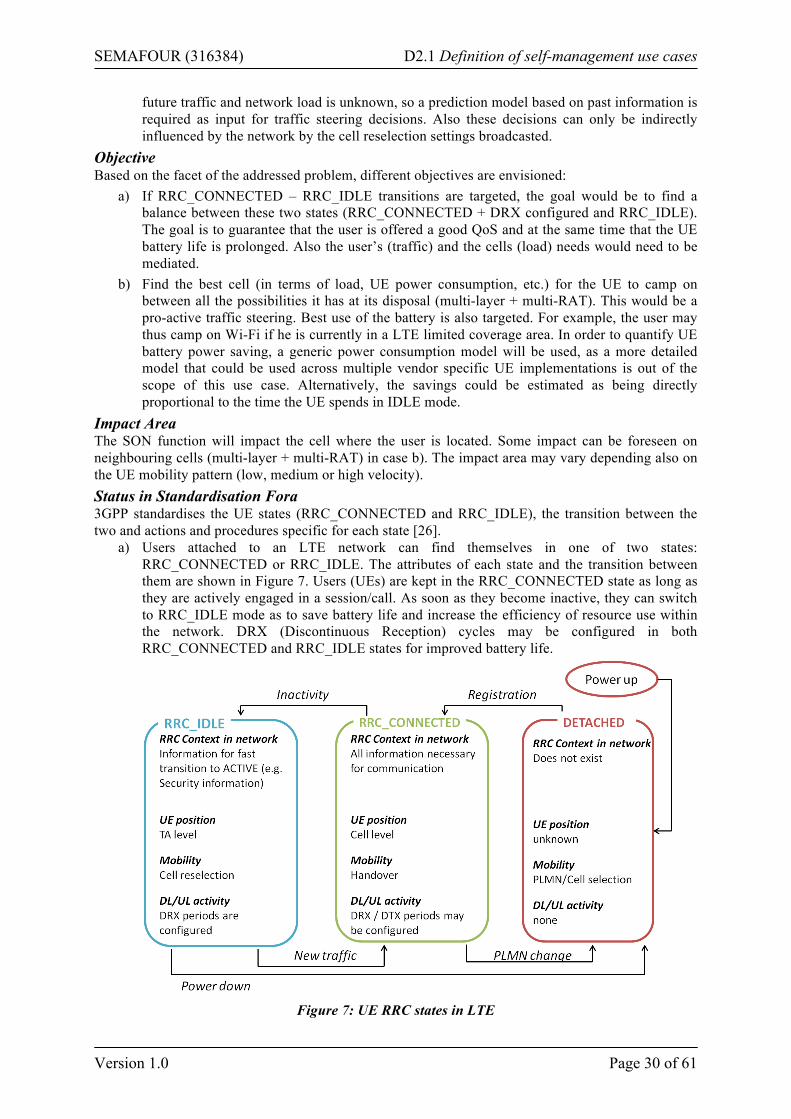
SEMAFOUR (316384) D2.1 Definition of self-management use cases
Version 1.0 Page 30 of 61
future traffic and network load is unknown, so a prediction model based on past information is required as input for traffic steering decisions. Also these decisions can only be indirectly influenced by the network by the cell reselection settings broadcasted.
Objective Based on the facet of the addressed problem, different objectives are envisioned:
a) If RRC_CONNECTED – RRC_IDLE transitions are targeted, the goal would be to find a balance between these two states (RRC_CONNECTED + DRX configured and RRC_IDLE). The goal is to guarantee that the user is offered a good QoS and at the same time that the UE battery life is prolonged. Also the user’s (traffic) and the cells (load) needs would need to be mediated.
b) Find the best cell (in terms of load, UE power consumption, etc.) for the UE to camp on between all the possibilities it has at its disposal (multi-layer + multi-RAT). This would be a pro-active traffic steering. Best use of the battery is also targeted. For example, the user may thus camp on Wi-Fi if he is currently in a LTE limited coverage area. In order to quantify UE battery power saving, a generic power consumption model will be used, as a more detailed model that could be used across multiple vendor specific UE implementations is out of the scope of this use case. Alternatively, the savings could be estimated as being directly proportional to the time the UE spends in IDLE mode.
Impact Area The SON function will impact the cell where the user is located. Some impact can be foreseen on neighbouring cells (multi-layer + multi-RAT) in case b). The impact area may vary depending also on the UE mobility pattern (low, medium or high velocity). Status in Standardisation Fora 3GPP standardises the UE states (RRC_CONNECTED and RRC_IDLE), the transition between the two and actions and procedures specific for each state [26].
a) Users attached to an LTE network can find themselves in one of two states: RRC_CONNECTED or RRC_IDLE. The attributes of each state and the transition between them are shown in Figure 7. Users (UEs) are kept in the RRC_CONNECTED state as long as they are actively engaged in a session/call. As soon as they become inactive, they can switch to RRC_IDLE mode as to save battery life and increase the efficiency of resource use within the network. DRX (Discontinuous Reception) cycles may be configured in both RRC_CONNECTED and RRC_IDLE states for improved battery life.
Figure 7: UE RRC states in LTE
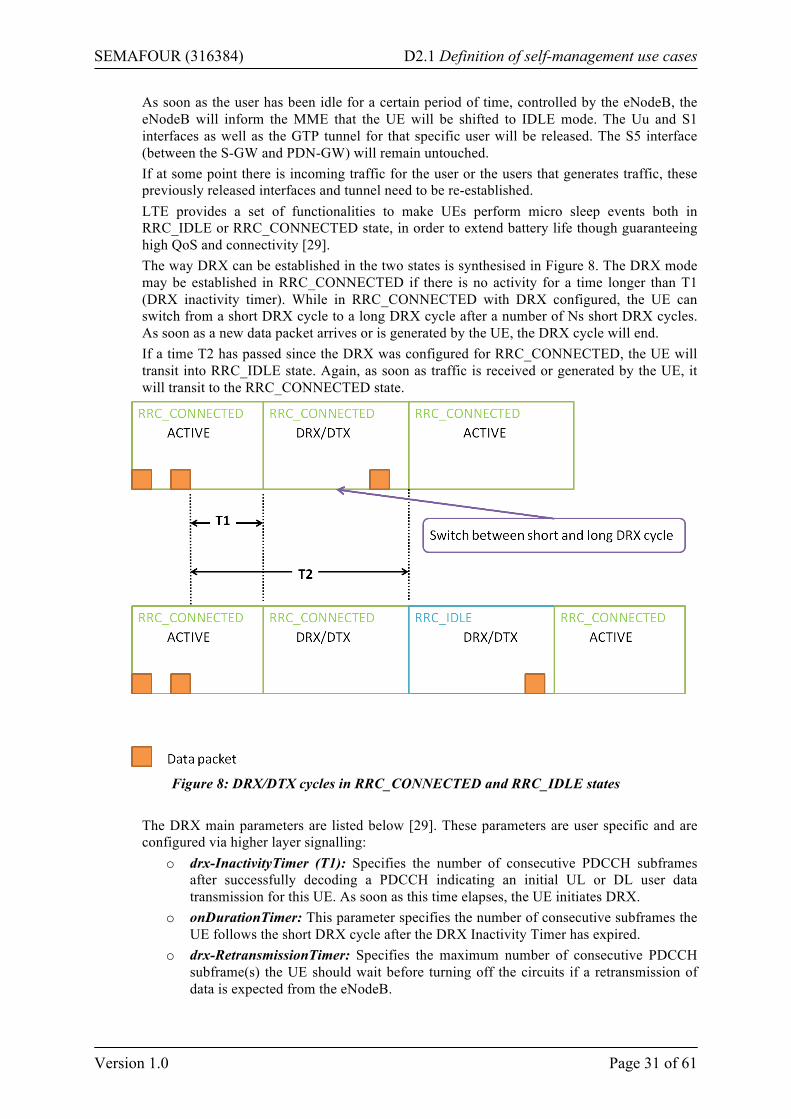
SEMAFOUR (316384) D2.1 Definition of self-management use cases
Version 1.0 Page 31 of 61
As soon as the user has been idle for a certain period of time, controlled by the eNodeB, the eNodeB will inform the MME that the UE will be shifted to IDLE mode. The Uu and S1 interfaces as well as the GTP tunnel for that specific user will be released. The S5 interface (between the S-GW and PDN-GW) will remain untouched. If at some point there is incoming traffic for the user or the users that generates traffic, these previously released interfaces and tunnel need to be re-established. LTE provides a set of functionalities to make UEs perform micro sleep events both in RRC_IDLE or RRC_CONNECTED state, in order to extend battery life though guaranteeing high QoS and connectivity [29]. The way DRX can be established in the two states is synthesised in Figure 8. The DRX mode may be established in RRC_CONNECTED if there is no activity for a time longer than T1 (DRX inactivity timer). While in RRC_CONNECTED with DRX configured, the UE can switch from a short DRX cycle to a long DRX cycle after a number of Ns short DRX cycles. As soon as a new data packet arrives or is generated by the UE, the DRX cycle will end. If a time T2 has passed since the DRX was configured for RRC_CONNECTED, the UE will transit into RRC_IDLE state. Again, as soon as traffic is received or generated by the UE, it will transit to the RRC_CONNECTED state.
Figure 8: DRX/DTX cycles in RRC_CONNECTED and RRC_IDLE states
The DRX main parameters are listed below [29]. These parameters are user specific and are configured via higher layer signalling:
o drx-InactivityTimer (T1): Specifies the number of consecutive PDCCH subframes after successfully decoding a PDCCH indicating an initial UL or DL user data transmission for this UE. As soon as this time elapses, the UE initiates DRX.
o onDurationTimer: This parameter specifies the number of consecutive subframes the UE follows the short DRX cycle after the DRX Inactivity Timer has expired.
o drx-RetransmissionTimer: Specifies the maximum number of consecutive PDCCH subframe(s) the UE should wait before turning off the circuits if a retransmission of data is expected from the eNodeB.
SEMAFOUR (316384) D2.1 Definition of self-management use cases
Version 1.0 Page 32 of 61
o drxShortCycleTimer: Specifies the number of consecutive subframes the UE shall follow for the Short DRX cycle before transitioning to the long DRX cycle.
o drxStartOffset: Specifies the subframe where the DRX Cycle starts. For highly predictable traffic (e.g., VoIP), the onDurationTimer can be set to 1 subframe and the DRX Cycle to 20 ms or 40 ms if packet staggering is used. For traffic that is more dynamic and in bursts with tight delay requirements, it is possible to configure the user with a drx-InactivityTimer where the packet scheduler can keep the UE awake by scheduling it within a certain time window [9]. DRX may be configured also in RRC_IDLE as described in [27]. One Paging Frame (PF) is one Radio Frame, which may contain one or multiple Paging Occasion(s) (PO). When DRX is used the UE needs only to monitor one PO per DRX cycle. PF and PO are determined using the DRX parameters provided in System Information (RadioResourceConfigCommon message).
b) Parameters relevant for the cell reselection procedure are included in different System Information Blocks (SIBs) [26]:
o SIB3 – common information for intra-freq, inter-freq and/or inter-RAT o SIB4 – intra-freq o SIB5 – inter-freq (eUTRAN) o SIB6 – inter-RAT (UTRAN) o SIB7 – inter-RAT (GERAN) o SIB8 – inter-RAT (CDMA2000)
These parameters are cell specific or cell pair specific. Currently the 3GPP standards propose that only a few parameters are scaled according to the cell frequency or radio (e.g., Treselection) and according to the UE speed (i.e., Qhyst and Treselection) [27]. Furthermore, no cell load information or the UE battery consumption is taken into account. These two pieces of information may play an important role in picking the best cell the UE can camp on. Absolute priorities of different E-UTRAN frequencies or inter-RAT frequencies may be provided to the UE in the system information, in the RRCConnectionRelease message, or by inheriting from another RAT at inter-RAT cell (re)selection [27]. ISR (Idle mode Signalling Reduction, see [30]) is not directly related. It targets the minimisation of the number of TAU/RAU procedures by registering and paging the UE in both 4G and 3G networks.
Temporal Aspects The temporal aspects of this use case will depend on the user traffic pattern (e.g., how long he is in CONNECTED mode before he is switched to IDLE, how often he is in a call/session, etc.).
• Scheduling/triggers: Periodical basis (in the order of seconds) but also based on input information changes and UE traffic
• Observation/monitoring time: In the order of seconds • Optimisation time: In the order of seconds • Parameter/reconfiguration enforcement time: In the order of seconds • Visibility delay: In the order of seconds to minutes • Protection time: In the order of seconds to minutes
Input Source The input sources needed by the use case will mainly refer to user characteristics:
• Traffic history • Traffic patterns • Service type • State transition history
SEMAFOUR (316384) D2.1 Definition of self-management use cases
Version 1.0 Page 33 of 61
• Cell reselection history • Speed • Load information of neighbouring cells (multi-layer & multi-RAT)
These parameters are needed for understanding and then predicting the user’s future activity. Most of this information is already exchanged between eNodeBs or available in the UE. For example, the speed of the UE should be determined by the UE itself and then appropriate scaling of cell reselection control parameters performed. It should be also possible to maintain a detailed account of traffic history and service type of each session in the UE. With access to this information, it would be possible to determine in advance when the user can be switched to RRC_IDLE or configure DRX cycles and steer it toward the best suited cell. The goal is to prove that there is a definite gain in having UE category tailored control parameter settings and this without introducing too many new functions in the UE or new messages between the UE and the eNodeB. Parameters to Adjust Depending on which facet is addressed different parameters will be adjusted:
a) DRX cycle parameters, eNodeB inactivity timer b) Cell reselection parameters (depending on layer or technology)
Actions The SON function will monitor input information and adjust control parameters. In parallel, by keeping track of user characteristics, UEs will be placed into different categories and prediction models for each category will be built. Simulation Approach The simulations have to cover a dense urban environment with mixed outdoor LTE and HSPA coverage. The LTE coverage will comprise of macro and pico cells while only HSPA macro cells will be considered. The simulations will investigate a dynamic environment, where users are static or moving and generate mixed traffic. Different traffic distributions, user behaviour as well as realistic UE mobility will be considered. Expected Results In the two defined cases different results are targeted as a result of the optimisation:
a) Increased battery life for the UE, minimised control signalling in the network, better use of network resources.
b) Better use of the combined network resources across different layers and technologies, minimisation of HOs subsequent to connection setup.
Measurements/Parameters/Interfaces to be Standardised [28] defines how information is exchanged across different RATs for SON purposes. Load information will be exchanged using Direct Information Transfer via the S1 interface (eNodeB- MME) using RIM (RAN Information Message) signalling. LTE load information concerning available capacity in the cell (DL and UL) can be accessed via the Composite Available Capacity Group [31]. As more detailed information regarding cell load may be needed over the involved interfaces, this may lead to new messages that need to be standardised. Also, depending on the level where the SON algorithm will be implemented (eNodeB or split between the eNodeB and the UE), a need may arise for new standardised message exchange; i.e., in an eNodeB centric implementation the information and history collected by the UE will need to be made available to the eNodeB. Architectural Aspects The SON function will be a distributed solution with the possibility of inter-layer/inter-RAT information exchange. Example (Informative Description) While connected users that are currently exchanging traffic with the network have the highest priority in terms of optimisation mechanisms, idle users should not be neglected. As not all users are equal, they should not be treated as such. Any given user in a mobile wireless network has a distinct pattern
SEMAFOUR (316384) D2.1 Definition of self-management use cases
Version 1.0 Page 34 of 61
to its traffic. This added to other user characteristics (history, speed, etc.) determines different classes of users. For these different classes, the transitions between RRC_IDLE and RRC_CONNECTED states will be optimised so that the UE battery life is improved and control signalling diminished. Once in IDLE state, the goal will be to find the best cell for the user to camp on. This pro-active traffic steering would then be responsible for diminished connection setup times and subsequent HOs. The studies in this sub use case will primarily focus on an intra-LTE deployment for sub case a) with an extension to multi-layer & multi-RAT for the purposes of sub case b). In this sub case indoor/outdoor transitions may also be of interest. The users present in both cases will be characterised by different speeds (low to high) and a wide range of traffic patterns and several services (voice, video, web). It is important to generate several different user profiles (in terms of traffic type, idle duration, etc.) in order to understand the impact that the DRX configurations and cell reselection procedure have on the QoS and the UE battery life. Potential Gain The gain from applying a SON mechanism to RRC_CONNECTED to RRC_IDLE transitions and cell reselection criteria will have as effect:
• Capacity and coverage improvement • QoS improvement • Indication on UE battery life enhancement
Related Use Cases • Multi-layer LTE/Wi-Fi traffic steering • High mobility
2.3.3 Tackling the Problem of High Mobility Users This use case is about optimizing the network performance of highly mobile users. In this context, high mobility occurs when the average amount of time that a user stays in a cell is low (~10 seconds), i.e., the time-of-stay is short. This use case will address the situations when high mobility poses a noticeable impact on the UE and network performance. The impact on the performance may be seen in:
• A reduced QoS experienced by the users in high mobility due to: o A cell stay time that is relatively short in comparison to the call time, to the time that
it takes to make a handover, to the duration of the data outage during the handover. o An increased number of call drops for users with high mobility as a result of the high
frequency of their handovers. • An increased signalling overhead in the core network due to handover signalling in the case
that a substantial amount of users in high mobility is present. There has to be a substantial amount of users that stay in a cell for a small amount of time in order to have an impact on the signalling in the core network. The velocity of the user and the path it follows through a cell are the key factors. Short time-of-stay can occur in two real-life situations:
a) When cell sizes are so small that even users with a low velocity perform frequent handovers b) When users move at a high velocity
In both situations the time between entering the cell and leaving it will be small and handovers will occur frequently. Situation a) might occur when there is a dense deployment of small cells, for instance in a shopping street/mall where users move through them at a small pace (for instance pedestrians). The cell inter-site distances in this case will be rather low (10-30 m) as is the speed at which the users are travelling (2-3 km/h). Situation b) might occur in macro cells along a busy highway or high-speed railroad: although the cells themselves are relatively large, the high pace of the users will cause the cell stay time to be low. There do not necessarily have to be many cells involved, the aforementioned problems might also occur in isolated cases where there are only a few cells experiencing problems.
SEMAFOUR (316384) D2.1 Definition of self-management use cases
Version 1.0 Page 35 of 61
This use case will investigate the problems described above in a multi-layer LTE deployment scenario. Additionally, multiple RATs might be considered as well. Objective The objective of this use case is to develop a SON function that improves the QoS of the highly mobile users and reduces the number of call drops and the signalling overhead in the core network by reducing the number of handovers and optimising the handover timing of the users by steering users to cells on which they can be camped for a longer time. First, a way to discriminate the UE mobility state, i.e., between highly mobile users and users that have low mobility or are stationary has to be determined. This is important in order to initiate the proper action(s) according to the mobility state. A distinction between UE mobility state can, for instance, be made based on the mobility history of users: users that have made many handovers in the (recent) past are probably moving and are expected to trigger more handovers in the (near) future while users that only made few or no handovers in the past are probably stationary and are expected to make only few handovers in the future. Another way to make a distinction between users is their location: on some places users will be more mobile than on other places. Network based user localisation techniques, e.g., OTDOA (Observed Time Difference of Arrival), can also be used to estimate user mobility. The SON functionality might also make a distinction between users that are more affected by the short time-of-stay and users that are less affected. Non-real-time sessions will, for instance, be less effected by data outage during handovers than real-time sessions. The suitability of the different methods to classify users will have to be evaluated. The evaluation criteria will depend on the traffic steering solution that will be developed in this use case. Secondly, based on the UE mobility state detection, different policies of what to do with these users have to be defined. The actions taken might differ from situation to situation. In case a) it might, for instance, be a good idea to steer highly mobile pedestrian users in a dense deployment of small cells to an overlaying macro cell to reduce their handover rate while keeping users which have low mobility connected to a micro/pico/femto cell for improved capacity and reducing the load in the macro cell. Another solution might be to not let the user handover to the strongest cell but instead let them skip cells along their path and hand them over to cells that are farther apart. This can of course only be done if this would not result in a call drop or serious degradation of the QoS. In case b) cells that are only crossed shortly near the edge might also be skipped in order to avoid frequent handovers. The efficiency of the different policies in different situations will be evaluated and a way to decide which policy should be applied in a certain situation will be defined. Impact Area The SON function will mostly affect areas where there is high mobility. These areas coincide with the cases mentioned in the description: areas where cells are small and areas where users have a high velocity. These include:
• Micro/pico/femto cells in shopping streets, shopping malls and other areas where there is a dense deployment of small cells both indoor as well as outdoor
• Macro cells covering the areas that contain a dense deployment of micro/pico/femto cells • Macro cells along a highway or a high-speed railway
The cells in such areas will be directly affected, as the handover behaviour of the users in these cells will be changed. There might also be a ripple effect towards cells that surround the cells directly affected; especially when these also implement SON functionality. This ripple effect is caused by the difference in handover behaviour of the directly affected cells. The load in a directly affected macro cell might, for instance, be higher due to the offload of traffic from the highly mobile users to this cell. This reduces the residual capacity in these cells for users coming from neighbouring cells. Note that this load might be re-distributed by steering users with low mobility to less loaded cells.
SEMAFOUR (316384) D2.1 Definition of self-management use cases
Version 1.0 Page 36 of 61
Status in Standardisation Fora Handover between base stations, both inter- and intra-RAT as well as between different layers has been standardised by 3GPP [25]. [26] also specifies the "Speed dependent scaling of measurement related parameters" which adjusts the time-to-trigger depending on the UE speed. The X2AP [31] provides ways to exchange of information like last visited cell information between the source and target eNodeBs during handover. [32] specifies the transfer of location information available at the UE. 3GPP Release 11 will contain TR 37.803 [33]. The major part of this technical report is devoted to mobility enhancements to accommodate mobility between two HeNodeBs and between a HeNodeB and the core network. Among others, it discusses various architectural options to implement an X2 interface between HeNodeBs. 3GPP Release 11 contains also TR 36.839 [34]. This report captures the conclusions and decisions from the Release 11 Study Item on the mobility enhancements for heterogeneous networks (HetNet) and will set the basis for the related Release 12 Work Item. Specifically, it includes observations on the mobility state estimation (MSE). The MSE is not as accurate in HetNet environments as in macro-only deployments since it does not take into account the cell size. Thus, MSE enhancements should be considered to improve the mobility performance of HetNets. Temporal Aspects The temporal aspects of this use case depend on the frequency at which handovers are triggered. This frequency does not necessarily have to be (very) high (i.e., handovers every tens of seconds): high mobility will in the first place be determined by the cell stay time.
• Scheduling: The main triggers for the SON functionality will be handover events or events that are related to handovers like measurement reporting. When there is a considerable amount of mobility (shopping mall, highway) these will occur regularly (every tens of seconds). In case of high-speed railways, for instance, these will occur less regular as trains will pass through the cell once every 10 minutes or so.
• Observation/monitoring – optimisation: The time that is needed for the SON functionality to monitor the system and the rate at which it will react will depend on the frequency at which handover events occur as a certain amount of measurements are needed in order to make a reliable observation. Depending on the handover frequency the monitoring period will be in the range of a couple of minutes to a couple of hours.
• Optimisation time: The optimisation step itself will happen rather quickly (in the order of seconds). The optimisation algorithm will have to make a decision on a new handover strategy and, in case other network components need to be informed, the communication will have to take place. This can all happen in a matter of seconds.
• Parameter/reconfiguration enforcement time - visibility delay - protection time: After each optimisation event it will take some time until the changes made by the algorithm to have an effect, as changes made by the SON function will only take effect and become visible when new handovers occur which allows users to be steered towards the right cell. This will also allow the system to stabilise. Depending on the handover frequency this will again be in the order of a couple of minutes.
Input Source In order to decide which users are highly mobile and which are not the SON functionality will mainly decide based on mobility history as well as the past and current position of the users. Also the load information in the target cells and coverage information which can be used to determine the QoS experienced by the users will be used to decide to which cells to steer different users. Parameters to Adjust The standardised parameters that will be adjusted by the SON functionality will mainly include the handover parameters like time-to-trigger and hysteresis as well as the cell-individual offsets.
SEMAFOUR (316384) D2.1 Definition of self-management use cases
Version 1.0 Page 37 of 61
Actions The SON functionality will monitor the mobility of users. It will classify the users based on their mobility pattern into highly mobile users and lesser mobile users. If necessary, further classifications will be made. The SON algorithm will monitor the handover performance of the system. Based on the handover performance of the system as well as the QoS performance of the users the algorithm will decide what the best handover strategy is for the highly mobile users. Actions taken by the algorithm might include:
• Steer users to macro cells in order to reduce the number of handovers • Steer users towards micro/pico/femto cells • Handover users to cells which are farther down along the trajectory of a user on the base of
user mobility prediction Simulation Approach This use case will be simulated in either a setting with a dense deployment of cells like a shopping street or a setting where there are fast moving users like an area with a highway running through it. There will be different types of users: some will be moving (rather) fast down the street or highway while others will be stationary or will move only at a slow pace. Users will make regularly set up sessions of different types that will last for a certain type that is related to the type of call. First simulations will be run with a standard MRO algorithm to create a baseline to compare the simulations results to. Later simulations where the designed solution is implemented in a certain part or even all of the base stations will be run. The core network will only be simulated in a limited fashion, as simulations will focus on the RAN. The impact of the different solutions on the signalling in the core will be derived from the amount of communication that is required for certain operations like performing a handover or exchanging information between base stations. Expected Results The main goal of this use case is to reduce the number of handovers made by a user and to elongate the average time-of-stay in case of high mobility as this will result in:
• An increased QoS experienced by the users as the accumulated time that a user is disconnected due to a handover is lower than without the optimisation
• A decreased number of call drops that are the result of frequent handovers • A decreased signalling overhead in the core network
Measurements/Parameters/Interfaces to be Standardised and Architectural Aspects The SON functionality will require information about the mobility of users and the load in the involved cells to be measured and exchanged. This information includes:
• Mobility information like handover frequency and location information • Load information about surrounding cells • RSRP and RSRQ information about neighbouring cells
As there is no need to make decisions on a large scale the SON functionality will likely be implemented in the base stations. There might, however, be a need to extend the X2 interface between base stations such that it is possible to exchange the information about the load and the mobility of users. Investigating whether or not the X2 interface should be extended in order to support additional information to be exchanged will be part of the work that has to be performed in the use case. There might also be a need for a central database that stores information about the mobility profile of users. Example (Informative Description) This use case could be applied in a shopping mall where there are a lot of micro/pico/femto cells. Users that are walking through the street will make frequent handovers while users that are sitting down do not/seldom make handovers. The algorithm will detect highly mobile users and steer them for instance to macro cells where they can remain connected to for a longer time while users with limited mobility can be steered towards micro/pico/femto cells.
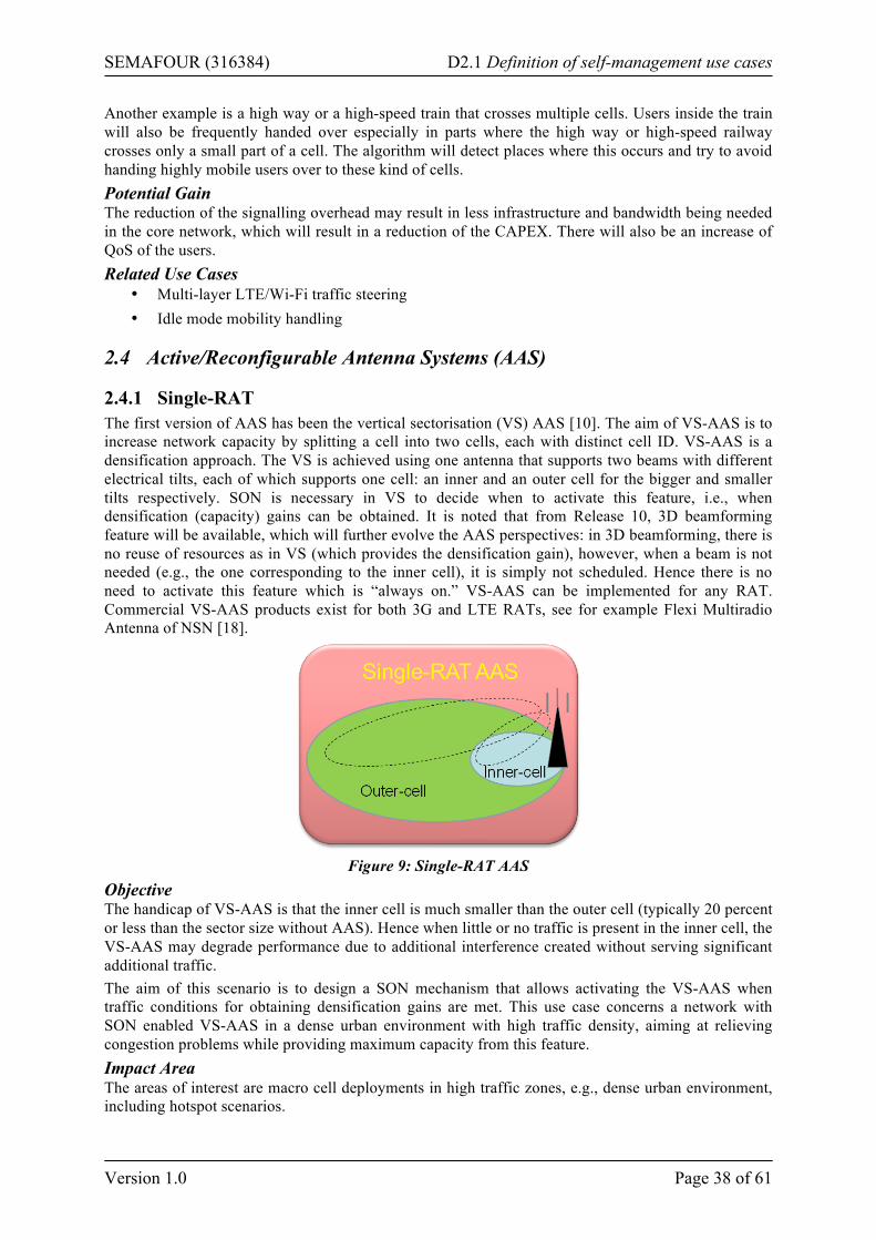
SEMAFOUR (316384) D2.1 Definition of self-management use cases
Version 1.0 Page 38 of 61
Another example is a high way or a high-speed train that crosses multiple cells. Users inside the train will also be frequently handed over especially in parts where the high way or high-speed railway crosses only a small part of a cell. The algorithm will detect places where this occurs and try to avoid handing highly mobile users over to these kind of cells. Potential Gain The reduction of the signalling overhead may result in less infrastructure and bandwidth being needed in the core network, which will result in a reduction of the CAPEX. There will also be an increase of QoS of the users. Related Use Cases
• Multi-layer LTE/Wi-Fi traffic steering • Idle mode mobility handling
2.4 Active/Reconfigurable Antenna Systems (AAS)
2.4.1 Single-RAT The first version of AAS has been the vertical sectorisation (VS) AAS [10]. The aim of VS-AAS is to increase network capacity by splitting a cell into two cells, each with distinct cell ID. VS-AAS is a densification approach. The VS is achieved using one antenna that supports two beams with different electrical tilts, each of which supports one cell: an inner and an outer cell for the bigger and smaller tilts respectively. SON is necessary in VS to decide when to activate this feature, i.e., when densification (capacity) gains can be obtained. It is noted that from Release 10, 3D beamforming feature will be available, which will further evolve the AAS perspectives: in 3D beamforming, there is no reuse of resources as in VS (which provides the densification gain), however, when a beam is not needed (e.g., the one corresponding to the inner cell), it is simply not scheduled. Hence there is no need to activate this feature which is “always on.” VS-AAS can be implemented for any RAT. Commercial VS-AAS products exist for both 3G and LTE RATs, see for example Flexi Multiradio Antenna of NSN [18].
Figure 9: Single-RAT AAS
Objective The handicap of VS-AAS is that the inner cell is much smaller than the outer cell (typically 20 percent or less than the sector size without AAS). Hence when little or no traffic is present in the inner cell, the VS-AAS may degrade performance due to additional interference created without serving significant additional traffic. The aim of this scenario is to design a SON mechanism that allows activating the VS-AAS when traffic conditions for obtaining densification gains are met. This use case concerns a network with SON enabled VS-AAS in a dense urban environment with high traffic density, aiming at relieving congestion problems while providing maximum capacity from this feature. Impact Area The areas of interest are macro cell deployments in high traffic zones, e.g., dense urban environment, including hotspot scenarios.
SEMAFOUR (316384) D2.1 Definition of self-management use cases
Version 1.0 Page 39 of 61
Status in Standardisation Fora Standardisation activity is on-going in 3GPP, covering antenna models for AAS [44], transmitter characteristic, BS AAS requirements and tests, channel models [45] (for the beamforming feature of AAS), etc. Temporal Aspects
• The time scale considered is that of traffic dynamics (arrival and departure of users), namely, of the order of a minute.
• Scheduling/triggers: Activation of the SON feature is event triggered. The event could be related to traffic or load level with respect to some predefined threshold, or to user arrival in the inner cell zone (to be studied).
• Observation/monitoring time: The SON feature is an “always on” and real time, namely, direct action taken upon a triggering event.
• Optimisation time: The learning of a (sub) optimal solution (e.g., the design of a controller) depends on the chosen learning/optimisation technique (e.g., hours to days for certain learning approaches, to be studied in the project). Once learning is “completed,” the actual reaction time is very short.
• Parameter/reconfiguration enforcement time: If only the amplifier is switched on and off (as in sleep mode management), enforcement time is of the order of milliseconds.
• Visibility delay: For elastic traffic, visibility delay is in the order of milliseconds. For streaming traffic, impact on QoS can be as well quasi instantaneous. The impact on blocking rate is of the order of minutes.
• Protection time: To be studied. Input Sources Sector load, number of connected users in inner and outer cell coverage zone (to be studied). Parameters to Adjust On/off of inner cell. Actions According to the learning algorithm, the SON algorithm should determine when to turn on/off the VS-AAS feature. Simulation Approach The AAS simulation for both self-optimisation and performance evaluation can be carried out on a network level simulator. Network size should be large enough in order to take into account interferences. Traffic characteristics should be well modelled. If, for example, elastic traffic is considered, non-full buffer traffic model is essential in order to assess the system capacity and the added value of the self-optimizing algorithms. Expected Results Significant capacity enhancement (or other related KPIs: reduction in blocking and outage rate). Measurements/Parameters/Interfaces to be Standardised VS-AAS does not need standardisation. If 3D beamforming is considered (e.g., switching between VS-AAS and 3D beamforming), then Channel State Information Reference Symbols (CSI-RS) are needed, which are defined in Release 10 [24]. Architectural Aspects Antennas supporting VS-AAS are needed. Example (Informative Description) Typical deployment of the VS-AAS can be envisaged in a dense urban environment, e.g., a city like Paris. In a first stage, the operator identifies the cells with high traffic/hot spots, where VS-AAS can be installed. Then, the selective deployment of the SON enabled VS-AAS can be carried out.
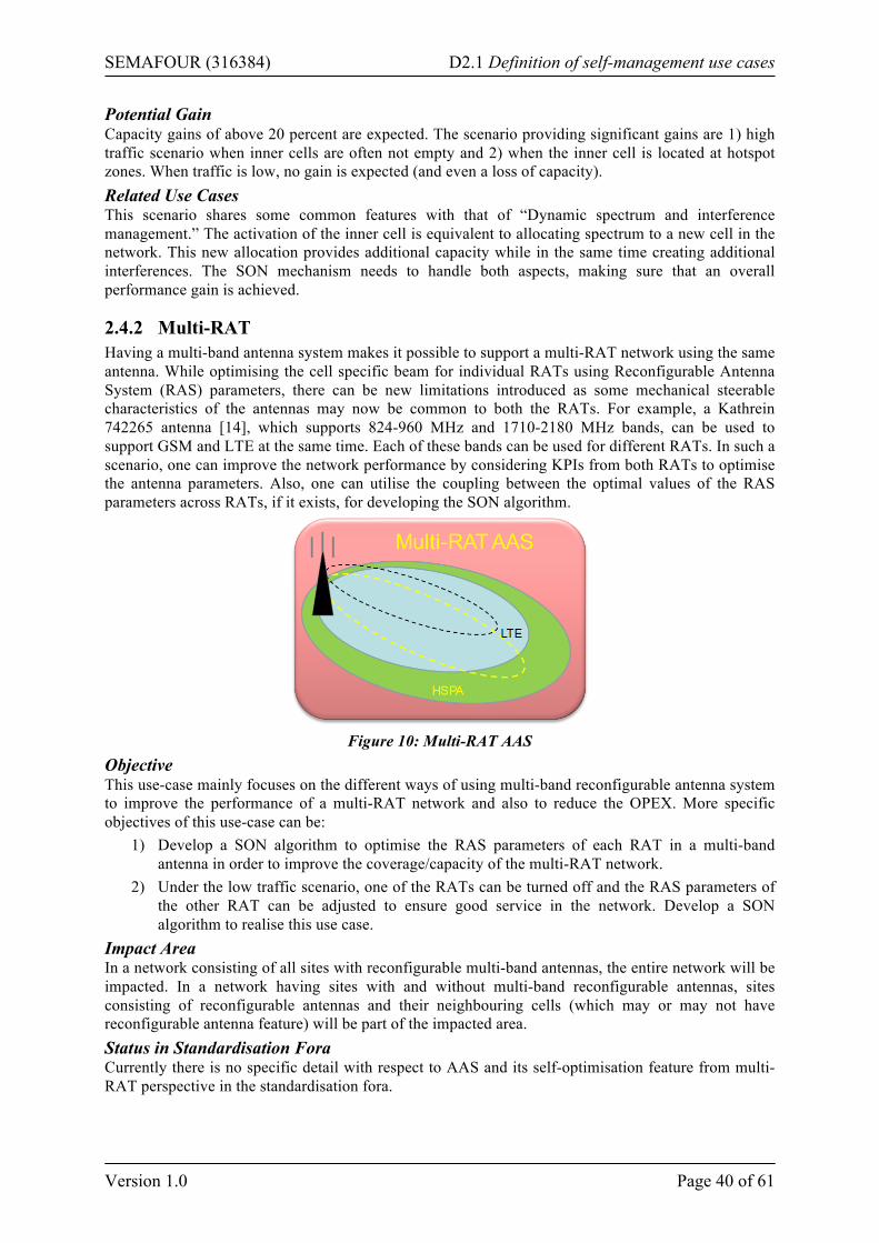
SEMAFOUR (316384) D2.1 Definition of self-management use cases
Version 1.0 Page 40 of 61
Potential Gain Capacity gains of above 20 percent are expected. The scenario providing significant gains are 1) high traffic scenario when inner cells are often not empty and 2) when the inner cell is located at hotspot zones. When traffic is low, no gain is expected (and even a loss of capacity). Related Use Cases This scenario shares some common features with that of “Dynamic spectrum and interference management.” The activation of the inner cell is equivalent to allocating spectrum to a new cell in the network. This new allocation provides additional capacity while in the same time creating additional interferences. The SON mechanism needs to handle both aspects, making sure that an overall performance gain is achieved.
2.4.2 Multi-RAT Having a multi-band antenna system makes it possible to support a multi-RAT network using the same antenna. While optimising the cell specific beam for individual RATs using Reconfigurable Antenna System (RAS) parameters, there can be new limitations introduced as some mechanical steerable characteristics of the antennas may now be common to both the RATs. For example, a Kathrein 742265 antenna [14], which supports 824-960 MHz and 1710-2180 MHz bands, can be used to support GSM and LTE at the same time. Each of these bands can be used for different RATs. In such a scenario, one can improve the network performance by considering KPIs from both RATs to optimise the antenna parameters. Also, one can utilise the coupling between the optimal values of the RAS parameters across RATs, if it exists, for developing the SON algorithm.
Figure 10: Multi-RAT AAS
Objective This use-case mainly focuses on the different ways of using multi-band reconfigurable antenna system to improve the performance of a multi-RAT network and also to reduce the OPEX. More specific objectives of this use-case can be:
1) Develop a SON algorithm to optimise the RAS parameters of each RAT in a multi-band antenna in order to improve the coverage/capacity of the multi-RAT network.
2) Under the low traffic scenario, one of the RATs can be turned off and the RAS parameters of the other RAT can be adjusted to ensure good service in the network. Develop a SON algorithm to realise this use case.
Impact Area In a network consisting of all sites with reconfigurable multi-band antennas, the entire network will be impacted. In a network having sites with and without multi-band reconfigurable antennas, sites consisting of reconfigurable antennas and their neighbouring cells (which may or may not have reconfigurable antenna feature) will be part of the impacted area. Status in Standardisation Fora Currently there is no specific detail with respect to AAS and its self-optimisation feature from multi-RAT perspective in the standardisation fora.
SEMAFOUR (316384) D2.1 Definition of self-management use cases
Version 1.0 Page 41 of 61
Temporal Aspects • The network coverage/capacity KPIs are measured in the order of days since the variations in
the traffic pattern, user distribution typically varies over time. • Scheduling/triggers: The RAS parameters will be evaluated periodically. For example, the
KPIs are observed every second day and the new RAS parameters will be derived based on the previous parameter values and their corresponding KPI values.
• Observation/monitoring time: The measurements have to be collected over a long period (days) in order to average out the impact of varying traffic pattern and user distribution in the network. However, shorter observation times can be used for the initial tuning of the network.
• Optimisation time: The optimisation algorithm convergence time could be of the order of weeks.
• Parameter/reconfiguration enforcement time: In order of tens of seconds. • Visibility delay: In the order of hours. • Protection time: To be studied.
Input Sources The inputs for this use case will be KPIs indicating coverage/capacity of the network. For example, the lower 5th percentile, which is an indication of the users experiencing poor data rates, and the median value of the overall downlink data rate can be used as the KPIs for indicating the downlink coverage in terms of minimal bit rate across the network and capacity of the network respectively. Parameters to Adjust The antenna down tilt and elevation half power beam widths of the vertical radiation pattern for each of the RATs will be tuned. Actions The reconfigurable antenna parameters of the multi-band antenna are periodically changed towards improving the capacity/coverage of the multi-RAT network. The SON algorithm will collect the KPIs for the observation period and based on the previously used parameter values and their resultant KPI values, new antenna parameter values will be derived. Simulation Approach The simulations are carried out with a capacity/coverage optimisation perspective. An urban network with mobile users requesting for different types of traffic is used in the scenario construction. The KPIs are collected from the network during the observation interval from all the RATs. The changes in the antenna parameters will be carried out based on the received information across the RATs. Initially, a constant antenna parameter set is used for all the sites and then the impact of SON algorithm on the capacity/coverage optimisation is evaluated. Expected Results The SON algorithm will adapt the reconfigurable antenna parameters of a multi-band antenna to improve the capacity/coverage of the network based on the optimisation objectives set by the operator. Measurements/Parameters/Interfaces to be Standardised No need of any standardisation of interfaces. Architectural Aspects A multi-band antenna capable of remote electrical tilt and vertical beam width changes is required. Example (Informative Description) In an urban deployment scenario, one network can support multi-RAT UEs using a single multi-band antenna. Due to small inter-site distances (in the order of 200-500 meters), it becomes necessary to have larger down tilt angles in order to reduce interference to the neighbouring cells. Larger down tilt angles are practically realised by having a combination of both electrical and mechanical tilting. Here, mechanical tilt is fixed which will be determined during the automatic cell planning phase and the electrical tilt of individual RATs will be optimised using the SON algorithm to improve the network performance. In other words, the mechanical tilt cannot be influenced directly by the SON algorithm
SEMAFOUR (316384) D2.1 Definition of self-management use cases
Version 1.0 Page 42 of 61
but it acts as a constraint during its development. The algorithm will try and find the optimal electrical tilt and vertical beam width for each of the RATs. Potential Gain Expected gains are in terms of capacity and coverage in a multi-RAT network with RAS feature compared to a multi-RAT network without RAS feature. The gain can also be in terms of reduced energy consumption if one considers the possibility of turning off of a RAT completely during low traffic hours provided that the other RAT is supported by the UEs. This energy saving gain is not expected to be significant as the legacy UEs will not possibly support both the RATs. The number of legacy UEs, which do not support multiple RATs, will be a limiting factor for the energy gains to be expected in this case. Related Use Cases Any change in the antenna parameter will have an impact of the cell coverage and the capacity which can in turn affect the KPIs related to other use cases like traffic steering and spectrum sharing use case.
2.4.3 Multi-layer / Multi-RAT Depending on the results of activities 2.4.1 and 2.4.2 the possibility of developing SON algorithms for a combined multi-layer / multi-RAT AAS network can be explored. First, the technical feasibility and market interest of such a solution should be evaluated, i.e., whether a multi-band AAS can also provide layer differentiation at the same time and whether such a solution has substantial benefits to offer. Several avenues can be considered for this activity such as:
• Combining VS AAS with multi-RAT AAS • Studying new advanced multi-layer AAS features • Deploying multi-RAT AAS in a macro/pico environment
The potential benefit of this activity will be evaluated after the first results of activities 2.4.1 and 2.4.2 are in. At that point, this activity will be pursued only if the involved partners agree on the importance of this study and the feasibility of concluding it within the available time frame.
SEMAFOUR (316384) D2.1 Definition of self-management use cases
Version 1.0 Page 43 of 61
3 Use Cases for Integrated SON Management
3.1 SON Coordination and Management Through High-Level Operator Goals
This section covers a set of related use cases that become relevant when two or more SON functions are simultaneously active/operational in the network and they interact among themselves. These SON functions are coordinated by the SON coordinator and are governed by the integrated SON management framework, which translates high-level operator objectives/goals to the SON level. It is possible to make a preliminary classification of the SON coordination and management use cases according to the temporal and/or spatial nature of the SON functions’ interactions as follows2:
Class 1: Scalable operation and management of identical SON functionalities The same SON functionality is active in neighbouring cells (the nature of the SON interactions is spatial). The integrated SON management framework covers several instances of the same or similar SON function over a zone of neighbouring cells. A typical example could be the network-wide deployment of MLB, where it is necessary to control/coordinate the interactions/conflicts between the MLBs of neighbouring cells, and to interact with the integrated SON management framework to enforce high-level objectives/goals. Note that such a situation is more prominent in multi-vendor environments, where a design-phase coordination/interworking between these different SON instances from different vendors cannot be expected.
Class 2: Local coordination and management of distinct/different SON functionalities A single cell2 having distinct/different SON functions is considered. It is assumed that neighbouring cells do not activate SONs.
Class 3: Scalable operation/coordination and management of distinct/different SON functionalities
Several neighbouring cells are considered, where in each cell two or more SON functions are in operation. The integrated SON management covers several instances of the same SON function for more than one SON. A typical example is the network-wide deployment of MRO + MLB + (e)ICIC. The above classification can be mapped onto the different sub-use cases that will be described later. Below are the characteristics common to all sub-use cases. The specific characteristics of each sub-use case will be detailed in the related subsection. Status in Standardisation Fora Except for the work item on interworking between MRO and MLB, which is currently standardised in 3GPP SA5 [46], this issue is not being treated in any standardisation forum. Temporal Aspects The temporal parameters/characteristics of the SON coordination and management are determined by those of the individual SON functionalities that are involved. A basic rule that can be applied to SON coordination and management is to group the coordinated functionalities according to their temporal scale characteristics. Note that each of the 3GPP SON functions has its temporal characteristics as implemented by each vendor. Therefore, coordination and management of the same set/combination of them may be different from one vendor to another. For proper SON coordination, the temporal characteristics/parameters of the involved SON functionalities must be taken into account. For example, the temporal granularity of the SON coordination (observation + action + decision period) must be at least as large as the maximum of the sum of the above temporal characteristics/parameters of each involved SON functionality. 2 Note that this classification is transparent with respect to the network itself, i.e., multi-RAT, multi-layer, etc.
SEMAFOUR (316384) D2.1 Definition of self-management use cases
Version 1.0 Page 44 of 61
Actions According to the rules and policies coming from the policy enforcement of the high-level operator objectives, the SON coordinator may perform different actions on the involved individual SON functions such as limiting the allowed control parameter ranges, setting the maximum allowed step sizes for control parameter changes, and the periodicity at which control parameter changes are allowed to be performed or the SON functions are allowed to perform changes. Simulation Approach To see the impact of the SON coordinator, at least two SON functions need to be implemented. These SON functions should act on the same parameters and/or impact the same KPIs. The simulation objective is to show the performance enhancement when potential conflicts or uncoordinated actions leading to a sub-optimal network performance are detected and corrected or avoided by the SON coordinator. The simulation should show how the system performance is closer to the high-level objectives with SON coordination than without SON coordination. Expected Results The SON coordinator detects and prevents of undesired behaviour (conflict between simultaneously active SON functions resulting in instability, inefficiency, bad QoS performance, etc.). Architectural Aspects and Measurements/Parameters/Interfaces to be Standardised Depending on the architecture of SON coordination framework (centralised, distributed, hybrid), the measurements/parameters/interfaces subject to standardisation vary. For centralised implementations, it is the signalling on the Itf-N interface which will be impacted, for distributed and hybrid implementations, both Itf-N and X2 interfaces will be impacted. Potential Gain An efficient coordination prevents from any network performance degradation due to conflicts, instability, etc., and thus improves global system stability. Hence, SON coordination contributes to the enhancement of the performance indicators related to the high-level operator objectives such as capacity, coverage and QoS improvements.
3.1.1 SON Operation in High Load Regime The high traffic growth in mobile networks is expected to saturate LTE/LTE-A networks in the upcoming years. Therefore, in a mature LTE network, high load network zones are expected. The operation of SON in such regime is of particular interest. Objective To cope with high traffic demand, self-optimisation functions will have to efficiently balance traffic between cells/layers/technologies, manage interference, maximise capacity/coverage and possibly manage energy consumption. Coordination of these functionalities is a key issue. Impact Area High-traffic zones with congested/saturated cells. Three deployment scenarios are considered: 1. LTE macro cell deployment only: The operator has only an LTE macro cell network and tries to
handle load problems using intra LTE RRM mechanisms without investing in any further deployment.
2. LTE HetNet deployment (with macro and/or micro and/or pico cells): The operator has an LTE network and deploys micro or pico cells to absorb the increased traffic demand.
3. Multi-RAT deployment (LTE and 3G, macro cell only): The operator has a multi-RAT 3G and LTE network and aims at solving load problems by using both intra LTE SON mechanisms and inter-RAT load balancing mechanisms.
Below, the sub-use cases of interest for each deployment scenario are described.
SEMAFOUR (316384) D2.1 Definition of self-management use cases
Version 1.0 Page 45 of 61
3.1.1.1 LTE Macro Layer Only The operator may choose to carry the traffic only with its macro LTE deployment. Objective In that case, Load Balancing (LB) among the macro LTE cells is of primary concern. Note that load balancing can be achieved by adapting the mobility parameters (MLB, a 3GPP SON function) or the (DL pilot) transmit powers. Typical Input Metrics/Indicators of Interest To detect conflicting or a sub-optimal behaviour of the system the variation in time of the metrics impacted by the SON functions is observed. These metrics comprise typical inputs of SON functions such as cell loads (as we consider load balancing) but also QoS metrics impacted by the considered SON functions such as File Transfer Time (FTT) for non-real time or best effort data applications, energy consumption, outage rate for real-time applications, throughput indicators (mean user, global, cell-edge average, etc.). At the coordinator level the variation of these metrics in time is analysed to detect oscillation or unexpected variation (whereas the SON functions observe the values of these metrics and not their variations). The spatial variation of the metrics can also be analysed by the coordinator (e.g., distribution of loads among cells). Involved SON Combinations With respect to the classification of SON combinations described in the section above, the following class combinations can be foreseen for this scenario: 1. Class 1 combination: MLB 2. Class 2 and class 3 combinations: Combinations (pairs, triplets, etc.) of LB/MLB, ICIC, CCO, ES
Typical Parameters to Adjust Common parameters are control ranges, setting the maximum allowed step sizes for control parameter changes, and the periodicity at which control parameter changes are allowed to be performed. For this case the parameters are: Intra-LTE HO parameters (hysteresis, CIO, TTT), intra-LTE idle mode mobility parameters, DL transmit characteristics (pilot power, antenna tilt, azimuth, etc.) of macro nodes, sub-band DL transmit powers of different FFR/SFR schemes for the macro LTE network.
3.1.1.2 Multi-layer The deployment of HetNets (multi-layer with several layers, i.e., macro, micro, pico, femto) are among the most promising solutions for allowing to increase considerably the network capacity. Management of HetNets poses complex configuration and optimisation problems. The large number of nodes in HetNets will call for using SON functionalities to its maximum extent, in order to manage admission to the network, mobility, interference and energy saving. Objective As is the case for the “LTE macro only” scenario, the main concern is to balance/steer the traffic among different layers through (mobility and/or other) LB mechanisms. Typical Input Metrics/Indicators of Interest To detect conflicting or sub-optimal behaviour of the system the coordinator observes the variation in time of the metrics impacted by the SON functions. The same metrics as for the previous scenarios could be considered. Involved SON Combinations With respect to the classification of SON combinations described in the section above, the following class combinations can be foreseen for this scenario: 1. Class 1 combination: Inter-layer MLB
SEMAFOUR (316384) D2.1 Definition of self-management use cases
Version 1.0 Page 46 of 61
2. Class 2 and class 3 combinations: Combinations (pairs, triplets, etc.) of LB/MLB3, inter-layer LB/MLB (including layer selection during initial access), MRO, inter-layer MRO, CCO (optimisation of cell size using DL transmission parameters such as power, antenna tilt/azimuth), (e)ICIC, ES, SEMAFOUR WP4 multi-layer SON functionalities.
Typical Parameters to Adjust Common parameters are control ranges, setting the maximum allowed step sizes for control parameter changes, and the periodicity at which control parameter changes are allowed to be performed. For this case the parameters are: Inter-layer HO parameters (hysteresis, CIO, TTT), inter-layer idle mode mobility parameters (e.g., layer selection during initial access), DL transmit characteristics (pilot power, antenna tilt, azimuth, etc.) of macro and low-power nodes, sub-band DL transmit powers of different FFR/SFR schemes for the LTE HetNet.
3.1.1.3 Multi-RAT In order to carry the increasing traffic demand, one of the immediate solutions is to balance/steer the load/traffic between different RATs, e.g., LTE and 3G/HSPA. Objective Traffic distribution strategy among RATs aims at having an optimal load distribution and an appropriate user distribution depending on each service characteristic to optimise both the global operator income and the user Quality of Service (QoS). Note that for multi-RAT environments, RAT selection at initial access is a means to achieve LB. Typical Input Metrics/Indicators of Interest To detect conflicting or a sub-optimal behaviour of the system the variation in time of the metrics impacted by the SON function is observed. The same metrics as for the previous scenarios could be considered, together with inter-RAT mobility indicators such as inter-RAT handover success rate. Involved SON Combinations With respect to the classification of SON combinations described in the section above, the following class combinations can be foreseen for this scenario: 1. Class 1 combination: Multi-RAT MLB 2. Class 2 and class 3 combinations: Combinations (pairs, triplets, etc.) of inter-RAT ANR, LB/MLB,
inter-RAT LB/MLB (including RAT selection at initial access), MRO, inter-RAT MRO, inter-RAT CCO (optimisation of cell size using DL transmission parameters such as power, antenna tilt/azimuth), ES, SEMAFOUR WP4 multi-RAT SON functionalities.
Typical Parameters to Adjust Common parameters are control ranges, setting the maximum allowed step sizes for control parameter changes, and the periodicity at which control parameter changes are allowed to be performed. For this case the parameters are: Inter-RAT HO parameters (hysteresis, CIO, TTT), idle mode mobility parameters (e.g., RAT selection at initial access), DL transmit characteristics (pilot power, antenna tilt, azimuth, etc.) of different RATs.
3.1.2 RAN Sharing in LTE Mobile network operators, in order to save CAPEX and OPEX, are increasingly sharing their Radio Access Networks (RANs). This will happen for LTE as well. Several RAN sharing scenarios can be envisaged, e.g., Multi Operator Core Network (MOCN), Multi Operator Radio Access Network (MORAN). In the shared RAN scheme, the RAN will be operated by a “Master Operator,” where shared eNodeBs will have non-shared neighbours operated by Sharing Operators. Potentially, operators will activate SON functions independently from one another and these could interfere with each other.
3 Unless otherwise indicated, SON functionalities such as MRO, MLB, CCO imply intra-LTE features
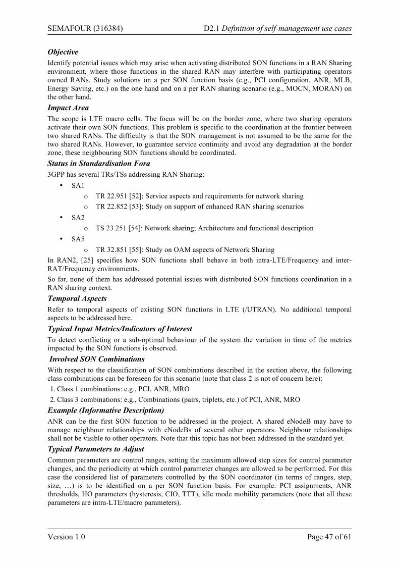
SEMAFOUR (316384) D2.1 Definition of self-management use cases
Version 1.0 Page 47 of 61
Objective Identify potential issues which may arise when activating distributed SON functions in a RAN Sharing environment, where those functions in the shared RAN may interfere with participating operators owned RANs. Study solutions on a per SON function basis (e.g., PCI configuration, ANR, MLB, Energy Saving, etc.) on the one hand and on a per RAN sharing scenario (e.g., MOCN, MORAN) on the other hand. Impact Area The scope is LTE macro cells. The focus will be on the border zone, where two sharing operators activate their own SON functions. This problem is specific to the coordination at the frontier between two shared RANs. The difficulty is that the SON management is not assumed to be the same for the two shared RANs. However, to guarantee service continuity and avoid any degradation at the border zone, these neighbouring SON functions should be coordinated. Status in Standardisation Fora 3GPP has several TRs/TSs addressing RAN Sharing:
• SA1 o TR 22.951 [52]: Service aspects and requirements for network sharing o TR 22.852 [53]: Study on support of enhanced RAN sharing scenarios
• SA2 o TS 23.251 [54]: Network sharing; Architecture and functional description
• SA5 o TR 32.851 [55]: Study on OAM aspects of Network Sharing
In RAN2, [25] specifies how SON functions shall behave in both intra-LTE/Frequency and inter-RAT/Frequency environments. So far, none of them has addressed potential issues with distributed SON functions coordination in a RAN sharing context. Temporal Aspects Refer to temporal aspects of existing SON functions in LTE (/UTRAN). No additional temporal aspects to be addressed here. Typical Input Metrics/Indicators of Interest To detect conflicting or a sub-optimal behaviour of the system the variation in time of the metrics impacted by the SON functions is observed. Involved SON Combinations With respect to the classification of SON combinations described in the section above, the following class combinations can be foreseen for this scenario (note that class 2 is not of concern here): 1. Class 1 combinations: e.g., PCI, ANR, MRO 2. Class 3 combinations: e.g., Combinations (pairs, triplets, etc.) of PCI, ANR, MRO
Example (Informative Description) ANR can be the first SON function to be addressed in the project. A shared eNodeB may have to manage neighbour relationships with eNodeBs of several other operators. Neighbour relationships shall not be visible to other operators. Note that this topic has not been addressed in the standard yet. Typical Parameters to Adjust Common parameters are control ranges, setting the maximum allowed step sizes for control parameter changes, and the periodicity at which control parameter changes are allowed to be performed. For this case the considered list of parameters controlled by the SON coordinator (in terms of ranges, step, size, …) is to be identified on a per SON function basis. For example: PCI assignments, ANR thresholds, HO parameters (hysteresis, CIO, TTT), idle mode mobility parameters (note that all these parameters are intra-LTE/macro parameters).
SEMAFOUR (316384) D2.1 Definition of self-management use cases
Version 1.0 Page 48 of 61
Expected Results It is expected that potential issues of interference between SON functions deployed in Hosting RAN Provider network and Participating Operators networks are identified. This will provide guidelines to mobile network operators on how to deploy/tune their SON functions in a RAN sharing context. It is also expected that OAM aspects will be addressed carefully. Potential Gain Identify the feasibility of having distributed SON functions deployed in a RAN sharing environment. Provide solutions.
3.2 Policy enforcement This use case is about “Linking SON management and coordination.” The basic assumption here is that the SON system shall make the network comply the best possible with higher-level policies. Those policies are assumed to lay out how to assess network performance and how to trade-off between incompatible goals. Furthermore, the management of the SON system shall be largely autonomous. Thus, there need to be:
• An automatism to explore which SON functions are available, what are the options to control them, how different control settings influence their behaviour.
• An algorithm/engine that deduces, based on what means of influence are available and what the (higher-level) goals (described by policies) are, how to effectively instrument and coordinate the available SON functions.
Obviously, both aims are challenging. But even if they were not fully accessible within this project, working towards them will help to understand good design practices for SON functions and how to effectively coordinate SON functions in action. The overarching goal is to facilitate the management of a SON system (SON functions and SON coordination) in a unified manner. For this it is necessary to start from the operator’s technical goals, rules and policies (Operator Policies) that describe and define the desired behaviour of the network. These are then to be transformed into dedicated rules and policies for the individual components of the SON system (SON Policies) at the level of individual SON functions and specific to the individual locations/cells/sectors/sites in the network they are operating at. The traditional assumption is that the break-down and implementation of these Operator Policies is mostly conducted manually through the human operator with some software support. The alternative this use case seeks to establish is to perform this mapping process automatically as part of the SON management. In addition, this shall include routinely checks on whether the present mapping is effective, and, if not, the automatic implementation of sensible alternatives.
Figure 11: Policy enforcement
Objective This use case aims at developing a Policy Transformation and Enforcement function for the automated refinement/mapping of the Operator Policies such that they can be implemented by SON functions and
SEMAFOUR (316384) D2.1 Definition of self-management use cases
Version 1.0 Page 49 of 61
a SON coordination function. This function shall relieve the human operator and considerably simplify the management of the SON system as a whole. Impact Area Affected are the parameter settings of SON management, SON coordination, and SON functions (at all levels) and thus the whole network. Status in Standardisation Fora 3GPP SA5 is addressing coordination management of SON. To which extent those activities have an impact on policy enforcement is subject to further analysis. There are currently several contributions to 3GPP SA5 regarding SON Coordination (e.g., [57], [58]), however, the topic itself is not yet described in standards documents (Technical Specifications). Temporal Aspects The policy enforcement is expected to take action under a number of conditions. Three examples are when being triggered explicitly, when reports on the network performance/quality suggest that tuning SON parameters might improve network quality in line with the operator policies, or when new network capabilities or equipment becomes available for control. There is no specific “response time” requirement. The policy enforcement has to cope with unannounced changes in any part of the network and shall not operate at a speed that makes interference with regular control actions of SON functions likely (i.e., control actions at a weekly, biweekly or monthly basis if not prompted otherwise). Input Sources Four distinct domains of input are identified, namely, 1) the domain referred to by operator policies; 2) data on the SON system, the SON functions, the SON coordinator, and the corresponding present parameter settings; 3) data on the network configuration (e.g., from Configuration Management and planning systems); and 4) reports on the network performance (e.g., from Performance Management and Fault Management). The “operator policies” mentioned above actually refer to high-level technical requirements, policies and rules for the operation of the network, which are, for example related to:
1. Customer satisfaction 2. Network sharing with other operators or service providers 3. Interoperability in multi-vendor environments 4. Trade-off between network capacity and energy saving 5. Network coverage in different area classes and along high mobility routes (highways, train
tracks, etc.) Parameters to Adjust The primary levers of the Policy Enforcement are the parameters and policies of the SON management as a whole, the parameters controlling SON functions (e.g., new policies, policies values such as triggering conditions, thresholds, permissible ranges, modification step size, update rate, permissible KPI ranges), and the parameters controlling the SON coordination function (e.g., triggering situations, ranking of SON-functions). Actions Examples for actions of the Policy Enforcement:
1. Modification of Event-Condition-Action policies of SON functions, regarding activation thresholds, targets, impacted area, timing, parameter tuning steps, permissible ranges, etc.
2. Modification of importance/ranking of SON-functions within the SON coordination function. 3. Benchmark observed network performance/quality in reference to given targets. 4. Deduce possible causes when targets are missed, analyse if deficits can be remedied based on
available SON functions, tune SON function parameters and SON coordination parameters. Simulation Approach The objective of this use case is to develop a Policy Transformation and Enforcement function that shall automatically analyse the Operator Policies and deduce input to the SON functions and a SON
SEMAFOUR (316384) D2.1 Definition of self-management use cases
Version 1.0 Page 50 of 61
coordination function in order to tune the network’s behaviour and performance in line with the Operator Policies. The simulations conducted for this use case will therefore need to simulate the network including all relevant SON functions. This will be the basis for the analyses of the network’s behaviour and performance in respect to the intended behaviour (as laid down in the Operator Policies). One integrated simulation approach covering all SON functions operating at the various time scales will most likely not be feasible with the available simulation technology. Instead of trying to perform huge integrated simulation, the simulation will be split into manageable pieces. In doing so, care will be taken that each individual scope is large enough. The criterion for this is whether it is possible to study the impact of the control of SON parameters on the network’s behaviour and to judge whether the intended effect is achieved for the subset of the SON functions. Depending on the subset of SON functions under study, different parts of an overall scenario (w.r.t. to technology mix, time scale, and geographical size) and different technical simulation approaches may be chosen. Expected Results
1. Provide a unified view of the SON system towards the operator, enabling SON functions and the SON coordination function to be managed as a whole
2. Autonomously maximise the compliance of network performance with performance targets by tuning SON function parameters and SON coordination parameters
3. Optimising network behaviour in line with higher-level policies 4. Ability to control network behaviour at the level of policies
Architectural Aspects and Measurements/Parameters/Interfaces to be Standardised Depending on how the SON system is set-up (centralised, distributed, or hybrid; one vs. multiple management systems, means of control for SON functions), the measurements/parameters/interfaces subject to standardisation vary. Note, however, that the primary flow of control will be at the level of controlling the SON system itself. These control interfaces are not subject to standardisation. Example (Informative Description) Assume the initial deployment goal of an operator for its LTE network is to provide broadband access to households and nomadic users. The high-level technical objective will mostly likely then be to provide maximum capacity and low latency to stationary users. In consequence, all relevant network parameters should be tuned accordingly and the SON function should contribute to this goal as well. As the network coverage is growing and areas of local coverage merge, the operator wants to optimise the network for a robust support of seamless mobility among cells. This is a change (or an expansion) of the high-level technical objectives. Once this new objective is entered into the policy enforcement system, the system has to retune the parameter settings for SON functions supporting the tuning of neighbour relations and handover parameters. Moreover, SON functions optimizing for capacity may be discouraged to do so at the expense of a degraded handover performance. Implementing all corresponding changes in the parameterisation of the SON functions is the task of the policy enforcement system. Potential Gain Improved efficiency in SON management is the key expected gain. In addition, mild improvements in network performance (on top of what the SON system provides anyway) and a minor contribution to OPEX savings are expected. An improved manageability of the network’s performance goals and the SON systems constitute a considerable value, which can presently not be qualified. Related Use Cases The WP5 use cases “SON coordination and management through high-level operator goals” and all “Decision Support System” related use cases.
3.3 Decision Support System The purpose of the decision support system is, complementary to the SON Management, to provide a unified feedback of the performance and on the operation of the SON system, and to help the human
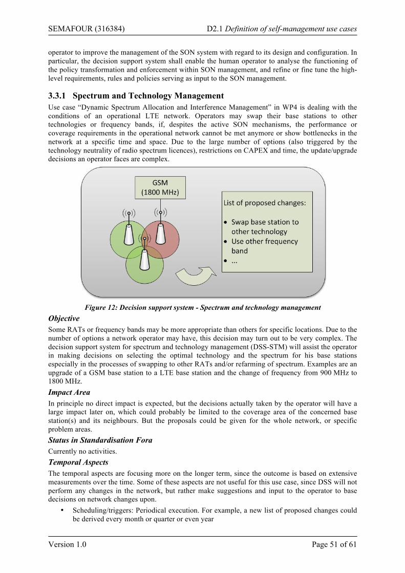
SEMAFOUR (316384) D2.1 Definition of self-management use cases
Version 1.0 Page 51 of 61
operator to improve the management of the SON system with regard to its design and configuration. In particular, the decision support system shall enable the human operator to analyse the functioning of the policy transformation and enforcement within SON management, and refine or fine tune the high-level requirements, rules and policies serving as input to the SON management.
3.3.1 Spectrum and Technology Management Use case “Dynamic Spectrum Allocation and Interference Management” in WP4 is dealing with the conditions of an operational LTE network. Operators may swap their base stations to other technologies or frequency bands, if, despites the active SON mechanisms, the performance or coverage requirements in the operational network cannot be met anymore or show bottlenecks in the network at a specific time and space. Due to the large number of options (also triggered by the technology neutrality of radio spectrum licences), restrictions on CAPEX and time, the update/upgrade decisions an operator faces are complex.
Figure 12: Decision support system - Spectrum and technology management
Objective Some RATs or frequency bands may be more appropriate than others for specific locations. Due to the number of options a network operator may have, this decision may turn out to be very complex. The decision support system for spectrum and technology management (DSS-STM) will assist the operator in making decisions on selecting the optimal technology and the spectrum for his base stations especially in the processes of swapping to other RATs and/or refarming of spectrum. Examples are an upgrade of a GSM base station to a LTE base station and the change of frequency from 900 MHz to 1800 MHz. Impact Area In principle no direct impact is expected, but the decisions actually taken by the operator will have a large impact later on, which could probably be limited to the coverage area of the concerned base station(s) and its neighbours. But the proposals could be given for the whole network, or specific problem areas. Status in Standardisation Fora Currently no activities. Temporal Aspects The temporal aspects are focusing more on the longer term, since the outcome is based on extensive measurements over the time. Some of these aspects are not useful for this use case, since DSS will not perform any changes in the network, but rather make suggestions and input to the operator to base decisions on network changes upon.
• Scheduling/triggers: Periodical execution. For example, a new list of proposed changes could be derived every month or quarter or even year
SEMAFOUR (316384) D2.1 Definition of self-management use cases
Version 1.0 Page 52 of 61
• Observation/monitoring time: The measurements have to be collected over a long term period (weeks or months) to identify problems within the network and make sophisticated proposals
• Optimisation time: n/a; since the DSS works offline the time required to run the algorithm is not of high interest
• Parameter/reconfiguration enforcement time: n/a; since the use case does not yield direct feedback to the network
• Visibility delay: Since the output would be a list of proposed changes the implementation could vary between months and years
• Protection time: n/a; since there is no direct feedback to the network Input Sources Input sources for this DSS-STM will be KPIs describing coverage, quality and capacity of the network as well as statistics on UEs in terms of which RATSs they can use. In addition, long-term observations and the outcome from different SON functions can be an indicator for potential starting points. Other sources may be defined at a later stage of the project, since the actual output of some SON functions cannot completely be foreseen yet. Decision making in terms of spectrum and technology selection will be based on the operator’s strategy. Therefore the operator policy is an important input as well. Parameters to Adjust None. Actions No specific SON activity required since there is no direct feedback to the network. Simulation Approach The objective of the DSS-STM is to make suggestions on optimal technology and the spectrum allocation for the base stations. The simulation aspect in this use case is two-fold:
1) The DSS-STM needs to back its suggestions by simulations: For a given network, performance readings, traffic variations, and UE population, the DSS-STM needs to simulate traffic growth and UE population changes as well as variations in the overall network configuration (technology, spectrum). For all these variations, some sort of performance prediction is necessary in order to qualify the most promising network reconfigurations.
2) Simulating the DSS-STM: To simulate the behaviour of DSS-STM, different cases of networks, different performance levels, different traffic intensities as well as their changes over time, different UE populations, different levels of SON, etc., could be investigated. To actually see the DSS working, a network in which low and high traffic, as well as overload in certain cells can be observed and change during time.
As mentioned above, in both cases the simulations have to cover a period of time of several weeks to months rather than hours or days. Expected Results With the given list of proposed changes a more effective use of available spectrum and technology can be achieved, if the changes will be implemented. As a side effect, this feature may even help to prepare strategies in spectrum auctions in the future. For the time being it is difficult to decide on the granularity of the list of suggestions. The determination of a reasonable granularity will be part of the research on this use case. Measurements/Parameters/Interfaces to be Standardised No specific actions required. Architectural Aspects No specific architecture required. Example (Informative Description) In a specific region an operator runs a GSM1800 network as well as a UMTS2100 network and has additional spectrum at 2600 MHz available. Severe capacity problems are observed, which cannot be
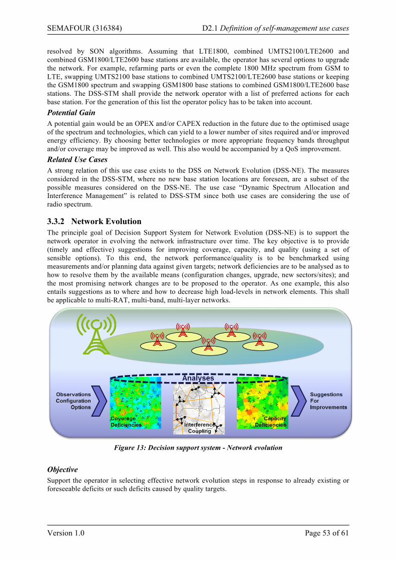
SEMAFOUR (316384) D2.1 Definition of self-management use cases
Version 1.0 Page 53 of 61
resolved by SON algorithms. Assuming that LTE1800, combined UMTS2100/LTE2600 and combined GSM1800/LTE2600 base stations are available, the operator has several options to upgrade the network. For example, refarming parts or even the complete 1800 MHz spectrum from GSM to LTE, swapping UMTS2100 base stations to combined UMTS2100/LTE2600 base stations or keeping the GSM1800 spectrum and swapping GSM1800 base stations to combined GSM1800/LTE2600 base stations. The DSS-STM shall provide the network operator with a list of preferred actions for each base station. For the generation of this list the operator policy has to be taken into account. Potential Gain A potential gain would be an OPEX and/or CAPEX reduction in the future due to the optimised usage of the spectrum and technologies, which can yield to a lower number of sites required and/or improved energy efficiency. By choosing better technologies or more appropriate frequency bands throughput and/or coverage may be improved as well. This also would be accompanied by a QoS improvement. Related Use Cases A strong relation of this use case exists to the DSS on Network Evolution (DSS-NE). The measures considered in the DSS-STM, where no new base station locations are foreseen, are a subset of the possible measures considered on the DSS-NE. The use case “Dynamic Spectrum Allocation and Interference Management” is related to DSS-STM since both use cases are considering the use of radio spectrum.
3.3.2 Network Evolution The principle goal of Decision Support System for Network Evolution (DSS-NE) is to support the network operator in evolving the network infrastructure over time. The key objective is to provide (timely and effective) suggestions for improving coverage, capacity, and quality (using a set of sensible options). To this end, the network performance/quality is to be benchmarked using measurements and/or planning data against given targets; network deficiencies are to be analysed as to how to resolve them by the available means (configuration changes, upgrade, new sectors/sites); and the most promising network changes are to be proposed to the operator. As one example, this also entails suggestions as to where and how to decrease high load-levels in network elements. This shall be applicable to multi-RAT, multi-band, multi-layer networks.
Figure 13: Decision support system - Network evolution
Objective Support the operator in selecting effective network evolution steps in response to already existing or foreseeable deficits or such deficits caused by quality targets.
SEMAFOUR (316384) D2.1 Definition of self-management use cases
Version 1.0 Page 54 of 61
Impact Area The scope of this use case is the network at large. However, an individual proposal will typically relate to small portions of the network such as a few geographically related cells. These cells may come belong to different layers (multi-layer) or different technologies (multi-RAT). Status in Standardisation Fora No 3GPP activities. Temporal Aspects The decision support system is not meant to automatically trigger any network changes. Suggestions on how to evolve the network over the coming months are computed on request or, possibly, routinely as a background task. The computation may take several hours. If any such suggestion is accepted, the corresponding network changes shall be exported in some sensible format that is likely to be importable by an operator’s planning and provisioning systems. The implementation of the proposed network changes are then outside the scope of the DSS-NE and be spread over weeks or months. Input Sources The DSS-NE depends on a several mandatory data source, but shall be capable to digest information from various sources beyond that: mandatory is information on the installed network configuration, its performance, the target performance, and what network changes are eligible (available configurations) in order to meet the targets. In each of these four domains, there are alternative and often complementing data sources. Generally speaking, the more refined information is available, the better can the decision support be. More specifically, mandatory is information on the current network configuration (CM, planning tools) and the current network performance (PM). Even better is when the configuration data and the performance measurements are available over a longer time period. Network quality target levels can, in principle, be specified in a simplistic manner such as some overall coverage level per technology and some overall capacity utilisation maximum per technology. But the more specific such targets depend on the environment (area and mobility classification, population density), the user demand, and service types, etc., the better the deficit analysis can be. Finally, the level of detail at which eligible network configuration changes are described, the better will the decision support system be able to analyse and propose only changes that match the specific situation in technical as well as in business terms. Parameters to Adjust Common option will be means to change coverage, interference (such as antenna tilt, transmission power to the extent they are not controlled or controllable by other SON functions, e.g., when an antenna has no option for remote tilt changes), simple capacity enhancements, and the adjustment of load level thresholds for various resources. Other means may be splitting cells, adding new sites, etc. The operator will determine which options shall be considered. Actions Pro- or reactively provide qualified proposals for network configuration changes (from a list of available options) as to meet performance targets. This includes highlighting where goals cannot be achieved using the available means. Simulation Approach The objective of this use case is to make suggestions on an optimised evolution of the network over time. There are two types of simulation relevant for this use case:
1. Simulations that are conducted in search for an optimised network evolution (i.e., as part of the use case): For a given network status, a record of performance readings, and traffic variations, the DSS-NE needs to simulate traffic growth as well as variations in the overall network configuration (within the available options) in order to value alternative network configurations. For all these variations, some sort of performance prediction is necessary in order to qualify the most promising network reconfigurations. Some traditional high-performance system-level network simulation engine may serve as the basis, which then needs to be extended in order to produce network (key) performance indicators as reported by the PM system. That is, similar
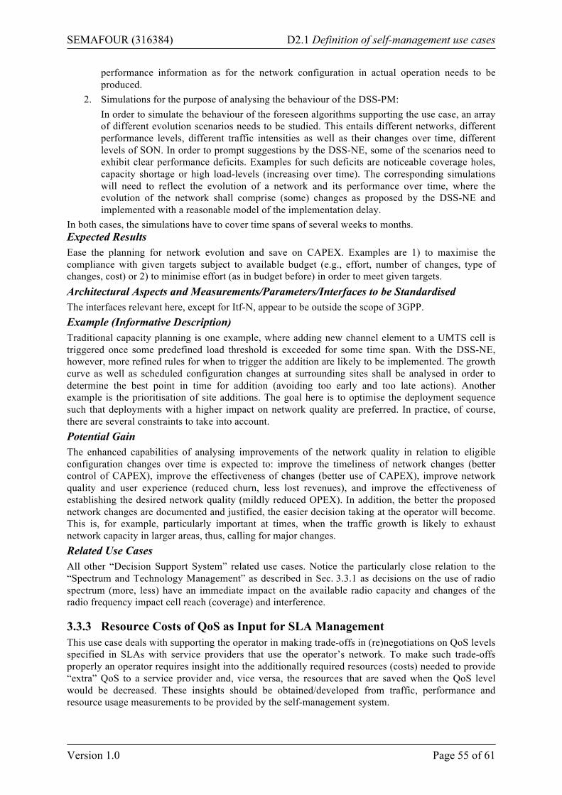
SEMAFOUR (316384) D2.1 Definition of self-management use cases
Version 1.0 Page 55 of 61
performance information as for the network configuration in actual operation needs to be produced.
2. Simulations for the purpose of analysing the behaviour of the DSS-PM: In order to simulate the behaviour of the foreseen algorithms supporting the use case, an array of different evolution scenarios needs to be studied. This entails different networks, different performance levels, different traffic intensities as well as their changes over time, different levels of SON. In order to prompt suggestions by the DSS-NE, some of the scenarios need to exhibit clear performance deficits. Examples for such deficits are noticeable coverage holes, capacity shortage or high load-levels (increasing over time). The corresponding simulations will need to reflect the evolution of a network and its performance over time, where the evolution of the network shall comprise (some) changes as proposed by the DSS-NE and implemented with a reasonable model of the implementation delay.
In both cases, the simulations have to cover time spans of several weeks to months. Expected Results Ease the planning for network evolution and save on CAPEX. Examples are 1) to maximise the compliance with given targets subject to available budget (e.g., effort, number of changes, type of changes, cost) or 2) to minimise effort (as in budget before) in order to meet given targets. Architectural Aspects and Measurements/Parameters/Interfaces to be Standardised The interfaces relevant here, except for Itf-N, appear to be outside the scope of 3GPP. Example (Informative Description) Traditional capacity planning is one example, where adding new channel element to a UMTS cell is triggered once some predefined load threshold is exceeded for some time span. With the DSS-NE, however, more refined rules for when to trigger the addition are likely to be implemented. The growth curve as well as scheduled configuration changes at surrounding sites shall be analysed in order to determine the best point in time for addition (avoiding too early and too late actions). Another example is the prioritisation of site additions. The goal here is to optimise the deployment sequence such that deployments with a higher impact on network quality are preferred. In practice, of course, there are several constraints to take into account. Potential Gain The enhanced capabilities of analysing improvements of the network quality in relation to eligible configuration changes over time is expected to: improve the timeliness of network changes (better control of CAPEX), improve the effectiveness of changes (better use of CAPEX), improve network quality and user experience (reduced churn, less lost revenues), and improve the effectiveness of establishing the desired network quality (mildly reduced OPEX). In addition, the better the proposed network changes are documented and justified, the easier decision taking at the operator will become. This is, for example, particularly important at times, when the traffic growth is likely to exhaust network capacity in larger areas, thus, calling for major changes. Related Use Cases All other “Decision Support System” related use cases. Notice the particularly close relation to the “Spectrum and Technology Management” as described in Sec. 3.3.1 as decisions on the use of radio spectrum (more, less) have an immediate impact on the available radio capacity and changes of the radio frequency impact cell reach (coverage) and interference.
3.3.3 Resource Costs of QoS as Input for SLA Management This use case deals with supporting the operator in making trade-offs in (re)negotiations on QoS levels specified in SLAs with service providers that use the operator’s network. To make such trade-offs properly an operator requires insight into the additionally required resources (costs) needed to provide “extra” QoS to a service provider and, vice versa, the resources that are saved when the QoS level would be decreased. These insights should be obtained/developed from traffic, performance and resource usage measurements to be provided by the self-management system.
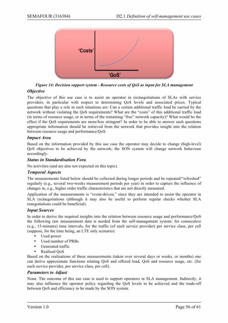
SEMAFOUR (316384) D2.1 Definition of self-management use cases
Version 1.0 Page 56 of 61
Figure 14: Decision support system - Resource costs of QoS as input for SLA management
Objective The objective of this use case is to assist an operator in (re)negotiations of SLAs with service providers, in particular with respect to determining QoS levels and associated prices. Typical questions that play a role in such situations are: Can a certain additional traffic load be carried by the network without violating the QoS requirements? What are the “costs” of this additional traffic load (in terms of resource usage, or in terms of the remaining “free” network capacity)? What would be the effect if the QoS requirements are more/less stringent? In order to be able to answer such questions appropriate information should be retrieved from the network that provides insight into the relation between resource usage and performance/QoS. Impact Area Based on the information provided by this use case the operator may decide to change (high-level) QoS objectives to be achieved by the network; the SON system will change network behaviour accordingly. Status in Standardisation Fora No activities (and are also not expected on this topic). Temporal Aspects The measurements listed below should be collected during longer periods and be repeated/“refreshed” regularly (e.g., several two-weeks measurement periods per year) in order to capture the influence of changes in, e.g., higher order traffic characteristics that are not directly measured. Application of the measurements is “event-driven,” since they are intended to assist the operator in SLA (re)negotiations (although it may also be useful to perform regular checks whether SLA renegotiations could be beneficial). Input Sources In order to derive the required insights into the relation between resource usage and performance/QoS the following raw measurement data is needed from the self-management system: for consecutive (e.g., 15-minutes) time intervals, for the traffic (of each service provider) per service class, per cell (suppose, for the time being, an LTE only scenario):
• Used power • Used number of PRBs • Generated traffic • Realised QoS
Based on the realisations of these measurements (taken over several days or weeks, or months) one can derive approximate functions relating QoS and offered load, QoS and resource usage, etc. (for each service provider, per service class, per cell). Parameters to Adjust None. The outcome of this use case is used to support operators in SLA management. Indirectly, it may also influence the operator policy regarding the QoS levels to be achieved and the trade-off between QoS and efficiency to be made by the SON system.
SEMAFOUR (316384) D2.1 Definition of self-management use cases
Version 1.0 Page 57 of 61
Actions 1) Retrieval of required raw input data from network/SON system, 2) processing and analysis of raw input data in order to derive the required insights for SLA management. No specific SON activity required. Simulation Approach To see this use case working the simulation need to cover a longer period during which several SLA (re)negotiations are effectuated (incl. the “entrance” and “departure” of service providers with the associated traffic loads). The realised changes in QoS levels and resource usage observed in the simulation should be in accordance with the a-priori estimated changes. Expected Results More appropriate SLAs (regarding price/QoS trade-off). A more effective use of available network capacity can be achieved. Improved anticipation to network extensions. Measurements/Parameters/Interfaces to be Standardised No specific actions required (the required measurement data seems available anyway). Architectural Aspects No specific architectural requirements. Example (Informative Description) If the operator is aware of the effects of increasing QoS objectives on resource usage and of the costs of allowing additional traffic load to its network (in terms of resource usage, or in terms of the remaining free network capacity) he can benefit from this knowledge and negotiate sharp SLAs with service providers. Potential Gain A potential CAPEX reduction due to more effective use of available network capacity. Higher service provider (and, eventually, also end-user) satisfaction due to improved price/quality ratios. Related Use Cases No critical relationships with other use cases.
SEMAFOUR (316384) D2.1 Definition of self-management use cases
Version 1.0 Page 58 of 61
4 Concluding Remarks This deliverable describes the self-management use cases identified in WP2. They are the basis and the starting point for the work to be performed in the SEMAFOUR project. For a fruitful development of self-management solutions, it is essential to have clear technical and non-technical requirements. These requirements are being derived in the requirement phase of the project in WP2 (in cooperation with WP4 and WP5). The central means is the collection of use cases on self-management in multi-RAT and multi-layer network scenarios defined in this document. As detailed in Chapters 2 and 3, these include dedicated multi-RAT and multi-layer SON use cases as well as the use cases of integrated SON management such as policy transformation and operational SON coordination. The requirements are input to WP4 and WP5 for the development of actual self-management solutions for (some to-be-selected subset of) the use cases. They also serve as a basis for validation and assessment of the developed solutions. Another important activity in the first stage of the project is to determine common reference scenarios and guidelines for simulation approaches, in order to ensure compatibility and harmonisation of the work by different partners and in different work packages. The requirements and use cases specified are being discussed together with an advisory board consisting of major European mobile network operators, in order to obtain feedback on and to allow the adjustment of the requirements, use case definitions and methodologies used in the project. This activity is driven by WP2. In the development phase, the work will be focused on 1) the development and validation of new concepts, methods and algorithms for self-management in multi-RAT and multi-layer network scenarios (in WP4, based on the use cases defined in WP2), and 2) integrated SON management taking care of harmonising the behaviour of different self-management functions according to the operator’s general network-oriented objectives (in WP5), based also on the use cases, requirements and scenarios defined in WP2. Finally, at the demonstration stage, which is prepared by WP3, the developed solutions for self-management of heterogeneous radio access networks will be demonstrated. A selection of the use cases collected in this report is the input to these demonstration activities. The research approach presented in this section states the key role that the use cases described in this deliverable play in the execution of the SEMAFOUR project. It is important to highlight that this is an on-going process, and the use cases described in this document may be modified during the following months, depending on the progress of WP4 and WP5 and the demonstration necessities of the project.
SEMAFOUR (316384) D2.1 Definition of self-management use cases
Version 1.0 Page 59 of 61
List of References [1] Yuan Yan; Anxin Li; Xinying Gao; Kayama, H., "A New Autonomous Component Carrier
Selection Scheme for Home eNB in LTE-A System,” Vehicular Technology Conference (VTC Spring), 2011 IEEE 73rd, vol., no., pp.1-5, 15-18 May 2011
[2] Wei-chih Hong; Zsehong Tsai, "Improving the autonomous component carrier selection for home eNodeBs in LTE-Advanced,” Consumer Communications and Networking Conference (CCNC), 2011 IEEE, vol., no., pp.627-631, 9-12 Jan. 2011
[3] Lu Zhang; Lin Yang; Tao Yang, "Cognitive Interference Management for LTE-A Femtocells with Distributed Carrier Selection,” Vehicular Technology Conference Fall (VTC 2010-Fall), 2010 IEEE 72nd, vol., no., pp.1-5, 6-9 Sept. 2010
[4] Garcia, Luis G. Uzeda.; Kovacs, Istvan Z.; Pedersen, Klaus I.; da Costa, Gustavo W. O.; Mogensen, Preben E., "Autonomous Component Carrier Selection for 4G Femtocells: A fresh look at an old problem,” in IEEE Journal on Selected Areas in Communications (JSAC), April 2012
[5] H. Liang, et al., ‘Realistic Indoor Wi-Fi and Femto cell deployment as the Offloading Solutions to LTE Macro Network’, in Proc. IEEE 76th Veh. Tech. Conf., September 2012
[6] P. Mogensen et al, ‘B4G local area: high level requirements and system design,” accepted to IEEE GLOBECOM, December 2012
[7] P. Fotiadis et al., “Multi-Layer Mobility Load Balancing in a Heterogeneous LTE Network,” Proc. IEEE 76th Veh. Tech. Conf., September 2012
[8] Y. Oya et al, “Access Selection in WCDMA and WLAN Multi-Access Networks’’, Proc. IEEE 61th Veh. Tech. Conf., May 2005
[9] Holma, Harri and Toskala, Antti, ‘LTE for UMTS - OFDMA and SC-FDMA Based Radio Access’, John Wiley & Sons, 2009
[10] O. Yilmaz, S. Hamalainen, J. Hamalainen, "System level analysis of vertical sectorization for 3GPP LTE," ISWCS 2009. pp. 453-457, Sept. 2009
[11] E. Perahia, R. Stacey, Next Generation Wireless LANs: Throughput, Robustness, and Reliability in 802.11n, Cambridge University Press, 2008
[12] K. Roebuck, IEEE 802.11ac: High-impact Technology - What You Need to Know: Definitions, Adoptions, Impact, Benefits, Maturity, Vendors, Emereo Pty Limited, 2011
[13] http://www.ict-samurai.eu/content/deliverables
[14] http://a2dcorp.us/pdf/kathrein/742265.pdf, Kathrein 742265 650 dual band antenna data sheet, Kathrein scala division, accessed on 6th of November 2012
[15] Smart WLAN Connectivity, Nokia Siemens Networks, Feb. 2011, http://www.nokiasiemensnetworks.com
[16] Ericsson Network Integrated Wi-Fi, Ericsson, Sep 2012, www.ericsson.com
[17] A 3G/LTE Wi-Fi Offload Framework: Connectivity Engine (CnE) to Manage, white paper, Qualcomm, June 2011
[18] White paper, “Active Antenna Systems, a step-change in base station site performance,” Nokia Siemens Networks, 2012
[19] 3rd Generation Partnership Project; Technical Specification Group Radio Access Network; High Speed Packet Access (HSDPA) multipoint transmission (Release 11) - 3GPP TR 25.872 V11.0.0 (2011-09)
SEMAFOUR (316384) D2.1 Definition of self-management use cases
Version 1.0 Page 60 of 61
[20] 3rd Generation Partnership Project; Overview of 3GPP Release 12 V0.0.5 (2012-09) - http://www.3gpp.org/ftp/Information/WORK_PLAN/Description_Releases/Rel-12_description_20120924.zip
[21] 3rd Generation Partnership Project Working Group; Technical Specification Group Radio Access Network; Evolved Universal Terrestrial Radio Access Network (E-UTRAN); Carrier-based HetNet ICIC use cases and solutions (Release 11) - V0.3.0 - (2012-05)
[22] 3rd Generation Partnership Project; Technical Specification Group Services and System Aspects; Architecture enhancements for non-3GPP accesses (Release 11) - 3GPP TS 23.402 V11.5.0 (2012-12)
[23] 3rd Generation Partnership Project; Technical Specification Group Core Network and Terminals; Proxy Mobile IPv6 (PMIPv6) based Mobility and Tunnelling protocols; Stage 3” - 3GPP TS 29.275 V11.4.0 (2012-09)
[24] 3rd Generation Partnership Project; Technical Specification Group Radio Access Network; Evolved Universal Terrestrial Radio Access (E-UTRA); Physical layer procedures - 3GPP TS 36.213 v.10.8.0, (2012-12)
[25] 3rd Generation Partnership Project; Evolved Universal Terrestrial Radio Access (E-UTRA) and Evolved Universal Terrestrial Radio Access Network (E-UTRAN); Overall description; Stage 2 (Release 11) - 3GPP TS 36.300 v11.3.0 (2012-09)
[26] 3rd Generation Partnership Project; Technical Specification Group Radio Access Network; Evolved Universal Terrestrial Radio Access (E-UTRA); Radio Resource Control (RRC); Protocol specification (Release 11), 3GPP TR 36.331 V11.1.0 (2012-09)
[27] 3rd Generation Partnership Project; Technical Specification Group Radio Access Network; Evolved Universal Terrestrial Radio Access (E-UTRA); User Equipment (UE) procedures in idle mode (Release 11) - 3GPP TS 36.304 V11.1.0 (2012-09)
[28] 3rd Generation Partnership Project; Evolved Universal Terrestrial Radio Access Network (E-UTRAN); S1 Application Protocol (S1AP) (Release 11) - 3GPP TS 36.413 V11.1.0 (2012-09)
[29] 3rd Generation Partnership Project; Technical Specification Group Radio Access Network; Evolved Universal Terrestrial Radio Access (E-UTRA); Medium Access Control (MAC) protocol specification (Release 11) - 3GPP TS 36.321 V11.0.0 (2012-09)
[30] 3rd Generation Partnership Project; Technical Specification Group Services and System Aspects; General Packet Radio Service (GPRS) enhancements for Evolved Universal Terrestrial Radio Access Network (E-UTRAN) access (Release 11) - 3GPP TS 23.401 V11.3.0 (2012-09)
[31] 3rd Generation Partnership Project; Technical Specification Group Radio Access Network; Evolved Universal Terrestrial Radio Access Network (E-UTRAN); X2 application protocol (X2AP) (Release 11) - 3GPP TR 36.423 V11.0.0 (2012-06)
[32] 3rd Generation Partnership Project; Technical Specification Group Radio Access Network; Evolved Universal Terrestrial Radio Access (E-UTRA); LTE Positioning Protocol (LPP) (Release 11) - 3GPP TR 36.355 V11.0.0 (2012-09)
[33] 3rd Generation Partnership Project; Technical Specification Group Radio Access Network; Universal Mobile Telecommunications System (UMTS) and LTE; Mobility enhancements for Home Node B (HNB) and Home enhanced Node B (HeNB) (Release 11) - 3GPP TR 37.803 V11.0.0 (2012-06)
[34] 3rd Generation Partnership Project; Technical Specification Group Radio Access Network; Evolved Universal Terrestrial Radio Access (E-UTRA); Mobility enhancements in heterogeneous networks (Release 11) - 3GPP TR 36.839 V11.0.0 (2012-09)
[35] RP-121198 “Carrier based HetNet ICIC for LTE,” September 2012
SEMAFOUR (316384) D2.1 Definition of self-management use cases
Version 1.0 Page 61 of 61
[36] RP-122038 “WLAN/3GPP Radio Interworking,” 3GPP TSG-RAN WG2 Meeting #58, Barcelona, Spain, December 4-7, 2012
[37] R3-112448, “Terminologies for carrier-based HetNet ICIC,” 3GPP TSG RAN WG3 Meeting #73bis, Zhuhai, China, 10th-14th October, 2011
[38] R3-112587, “Considerations on operational cell carrier selection,” 3GPP TSG RAN WG3 Meeting #73bis, Zhuhai, China, 10th-14th October, 2011
[39] R3-113074, “Text proposal for the Autonomous Operational Carrier Selection,” 3GPP TSG-RAN WG3 Meeting #74, San Francisco, USA, November 14-18, 2011
[40] R1-092573 “Mechanism for Cell Specific Component Carrier Usage,” Nokia Siemens Networks, Nokia, Qualcomm Europe, China Unicom
[41] R3-120284, “Motivation and relevance of autonomous operational carrier selection,” Nokia Siemens Networks, Alcatel-Lucent, Orange, Potevio, DAC-UPC, New Postcom
[42] R3-121148, “Operational carrier optimization - solution and performance,” DAC-UPC
[43] R3-121149, “Additional carrier selection for pico eNB - solution and performance,” DAC-UPC
[44] R4-120305 “Proposal to Modeling Active Antennas,” 3GPP TSG-RAN WG4, Kathrein, February 2012
[45] R1-111436, “Channel modeling considerations for vertical beamforming,” 3GPP TSG-RAN WG1, May 2011
[46] Work Task “LTE Self-Organizing Networks (SON) coordination management,” Rel-11, 3GPP SA5
[47] R3-121802, “Carrier-based HetNet ICIC use cases and solutions (Release 11),” TR 03.024 V.0.4.0, August 2012
[48] RP-122033, ‘Study Item Description: Small Cell enhancements for E-UTRA and E-UTRAN - Higher-layer aspects’, 3GPP TSG-RAN Meeting#58, Barcelona, Spain, December, 2012
[49] IEEE 802 OmniRAN, http://www.ieee802.org/OmniRANsg/
[50] IEEE 802.11™: Wireless LANs, http://standards.ieee.org/findstds/standard/
[51] Hotspot 2.0 Technical Specification v1.0.0, Wi-Fi Alliance, https://www.wi-fi.org/
[52] 3rd Generation Partnership Project; Technical Specification Group Services and System Aspects; Service aspects and requirements for network sharing, (Release 11), 3GPP TR 22.951
[53] 3rd Generation Partnership Project; Technical Specification Group Services and System Aspects; Study on support of enhanced RAN sharing scenarios, (Release 11), 3GPP TR 22. 852
[54] 3rd Generation Partnership Project; Technical Specification Group Services and System Aspects; Network Sharing; Architecture and functional description(Release 11); 3GPP TS 23.251
[55] 3rd Generation Partnership Project; Technical Specification Group Services and System Aspects; Telecommunication management; Study on OAM aspects of Network Sharing (Release 12); 3GPP TR 32.851
[56] RP-122037, “Proposal for a Study Item on next-generation SON for UTRA and LTE,” 3GPP TSG-RAN Meeting #58, Barcelona, Spain, 4-7 Dec 2012
[57] S5-130175, “Comments on SON Co-ordination efforts”, 3GPP TSG SA WG5 (Telecom Management) Meeting #87, Malta, January 14-18, 2013
[58] S5-130188, “SON coordination use case analysis’, 3GPP TSG SA WG5 (Telecom Management) Meeting #87, Malta, January 14-18, 2013