Embed Size (px)
Citation preview
LMS / LMI 400
Definition of telegrams betweenthe user interface and LMS or LMI systems via
RS 422/RS 232
Version 05.00
GB 05 Auto Ident
Tel
egra
mlis
ting
LMS/LMI 400 Definition of interface and telegram traffic Version 05.00 Page 2 / 99
Contents
1 SYSTEM DESCRIPTION 5
1.1 LMS 2XX 5
1.2 LMI 400 5
1.3 Definition of the run-up period for LMI 400 and LMS 6
1.4 Important interfaces for customer-specific evaluation software 7
2 DEFINITION OF INTERFACE BETWEEN LMS OR LMI 400 AND HOST COMPUTER 8
2.1 Electrical interface: 8
2.2 Transfer and data format: 8
2.3 LMS and LMI 400 telegram structure: 92.3.1 Structure of the LMS xx1 to xx5 and xx6 status byte 122.3.2 Structure of the LMI 400 status byte 12
2.4 Formation of the CRC16 checksum 13
3 EXAMPLE OF COMMUNICATION PROCEDURE FOR RECEIVING MEASURED VALUESFROM LMS OR LMI 400 16
3.1 Receipt of an LMS scan's complete measured value set in real time 16
3.2 Receipt of averaged measured values 17
4 AVAILABILITY OF TELEGRAMS 18
5 DESCRIPTION OF AVAILABLE TELEGRAMS 19
5.1 Data direction: Host computer -> LMS / LMI 400 195.1.1 Start sequence for download to the flash eprom (0BH) 195.1.2 Download data for the flash eprom (0CH) 195.1.3 Initialisation and reset (10H) 205.1.4 Select or change operating mode (20H) 215.1.5 Request for measured values (30H) 235.1.6 Request for sensor status (31H) 245.1.7 Request for error telegram (32H) 245.1.8 Request for test in diagnostic mode (33H) 255.1.9 Request for a memory dump (34H) (version 1) 255.1.10 Request for a memory dump (34H) (version 2) 255.1.11 Request / set operating data counters (35H) 265.1.12 Request for averaged measured values (36H) 275.1.13 Request for partitioned measured values (37H) 275.1.14 Request for LMI configuration (38H) 275.1.15 Request for evaluation case definitions (39H) 285.1.16 Request for LMS type (3AH) 285.1.17 Change of LMS variant (3BH) 285.1.18 Request for reference target values (3CH) 285.1.19 Request for correction values (3DH) 295.1.20 Request for measured values with field values (3EH) 295.1.21 Request for averaged partitioned measured values (3FH) 295.1.22 Configuration of fields A, B or C (40H) 305.1.23 Change active field group (41H) 315.1.24 Change password (42H) 32
LMS/LMI 400 Definition of interface and telegram traffic Version 05.00 Page 3 / 99
5.1.25 Request for measured values and paritioned remission values (44H) 325.1.26 Request for configured fields (45H) 325.1.27 Teach mode for field configuration (46H) 335.1.28 Configuration of a dynamic rectangular field (048H) 345.1.29 Request state of field outputs (04AH) 345.1.30 Configuration of a dynamic segmented field (4BH) 355.1.31 Activation of a dynamic field using index or simulated speed (4CH) 365.1.32 Activation / deactivation of outputs (4DH) 365.1.33 Read the state of the inputs (4EH) 365.1.34 Define or simulate input information to change an evaluation case (4FH) 375.1.35 Carry out calibration (50H) 375.1.36 Setting the detection threshold (51H) 385.1.37 Read and write end test data (52H) 385.1.38 Define permanent baud rate or sensor type (66H) 395.1.39 Define device address (67H) 395.1.40 Activate / deactivate laser transmitter (68H) 395.1.41 Definition of angular range for positioning aid (69H) 405.1.42 Definition of LMI configuration (70H) 415.1.43 Definition of an evaluation case (72H) 435.1.44 Read LMS configuration (74H) 465.1.45 Request for measured values with reflectivity information (75H) 465.1.46 Request for measured values in Cartesian co-ordinates (76H) 475.1.47 Define LMS-2xx-xxx06 configuration (77H) 485.1.48 Definition of correction parameters (78H) 535.1.49 Definition of distance correction parameters (79H) 535.1.50 Definition of parameters for reflectivity image evaluation (7AH) 53
5.2 Data direction LMS / LMI -> Host computer 545.2.1 Message after Power On (90H) 545.2.2 Confirmation of software reset telegram (91H) 545.2.3 Not acknowledge (92H) 555.2.4 Response to change of operating mode (A0H) 555.2.5 Response to request for measured values (B0H) 565.2.6 LMS sensor status (B1H) 575.2.7 LMS sensor status (B1H) 605.2.8 LMI status (B1H) 645.2.9 Error message / test message (B2H) 665.2.10 Memory dump on request (B4H) version 1 675.2.11 Send operating data counters 675.2.12 Send averaged measured values (response from LMS and LMI) (B6H) 685.2.13 Send partitioned measured values (B7H) 695.2.14 LMI configuration data (B8H) 705.2.15 Definition of data for an evaluation case (B9H) 705.2.16 Information on LMS type (BAH) 705.2.17 Response to change of LMS variant (BBH) 705.2.18 Reference target values (BCH) 715.2.19 Correction values (BDH) 725.2.20 Send measured value with field values (BEH) 735.2.21 Send averaged partitioned measured values (BFH) 745.2.22 Response to field configuration (C0H) 755.2.23 Change active field group (C1H) 765.2.24 Confirmation of new password (C2H) 765.2.25 Response to request for measured values with partitioned remission values (C4H) 775.2.26 Configuration data for programmed fields (C5H) 785.2.27 Response in teach mode (C6H) 795.2.28 Response to configuration of a dynamic rectangular field (C8H) 815.2.29 Response to request for state of field outputs (CAH) 815.2.30 Response to configuration of a dynamic segmented field (CBH) 825.2.31 Response to switching of dynamic field using index or simulated speed (CCH) 835.2.32 Response to activation / deactivation of outputs (CDH) 845.2.33 Current input data (CEH) 845.2.34 Response to definition of input information for an evaluation case change (CFH) 855.2.35 Response to calibration (D0H) 855.2.36 Response to setting the detection threshold (D1H) 855.2.37 Response to read and write end test data (D2H) 865.2.38 Response to permanent baud rate definition (E6H) 865.2.39 Response to definition of LMS / LMI address (E7H) 875.2.40 Response to activate / deactivate laser transmitter (E8H) 875.2.41 Response to definition of angular range for assisting positioning (E9H) 875.2.42 Response to LMI configuration (F0H) 885.2.43 Response to definition of an evaluation case (F2H) 885.2.44 Current LMS configuration (F4H) 885.2.45 Measured values with reflectivity information (F5H) 895.2.46 Response to request for measured values in Cartesian coordinates (F6H) 915.2.47 Response to definition of LMS-2xx-xxx06 configuration (F7H) 925.2.48 Response to definition of correction parameters (F8H) 92
LMS/LMI 400 Definition of interface and telegram traffic Version 05.00 Page 4 / 99
5.2.49 Response to definition of distance correction parameters (F9H) 925.2.50 Response to definition of parameters for reflectivity image evaluation (FAH) 93
6 LIST OF ERROR NUMBERS FOR LMS AND LMI 94
6.1 LMS type 1-5 error list 94
6.2 LMS-2xx-xxx06 error list 95
6.3 LMI error list 96
7 OVERFLOW VALUES 98
8 ABBREVIATIONS AND HINTS 99
LMS/LMI 400 Definition of interface and telegram traffic Version 05.00 Page 5 / 99
1 SYSTEM DESCRIPTION1.1 LMS 2XXThe LMS2XX is a divergent laser scanner with a maximum scanning angle of 180° and a lateral resolutionwhich can be variably defined between 0.25° and 1°. The accuracy of measurement in a single shot isabout ± 2 cm. From a baud rate of 500 Kbaud upwards, the LMS is capable of transferring all measuredvalues in real time using a serial interface.Please note the following information for the telegrams described for the LMS 2XX:We distinguish between two groups of scanners:
LMS with a resolution of 10 mm: LMS2xx-xx06LMS with a resolution of 50 mm: LMS2xx-xx01-...05
Only certain telegrams are valid for all LMS types. See the table in chapter 4 for the availability of thetelegrams.
1.2 LMI 400The LMI 400 is the universal evaluation unit for the distance measurement values generated by the LMS.The LMI 400 receives the data from the LMS in real time using an asynchronous serial interface so thatevery scan can be processed by the LMI 400. A maximum of 4 LMS sensors can be physically connectedto an LMI 400 unit. However, data from only 2 LMS sensors can be evaluated at the same time or duringsimultaneous operation.
Up to 4 double fields or 2 triple fields can be administered by the LMI 400, these can be assigned LMS2XXunits as desired.
The LMI 400 offers two independent outputs, OUT1 and 2. Each of these outputs in turn offer 3independent switching signals, which are permanently allocated to the three types of field described as fieldA, field B and field C.
FIELD TYPE can be allocatedto ------->>
OUTPUT OUT1 OUTPUT OUT2
Field A OUT1 A OUT2 AField B OUT1 B OUT2 BField C OUT1 C OUT2 C alternatively also for
pollution message.
The triple fields (field A, field B, field C) or double fields (field A, field B) are labeled using an index and canthus be received by or transmitted to the LMI 400 without risk of misinterpretation.A maximum of two triple fields is possible (index numbers 1 and 2).A maximum of four double fields is possible (index numbers 1 to 4).
For diagnosis, setting parameters and configuration, the LMI 400 has a second asynchronous serialinterface which can be used for sending data to a superior host computer. The following telegramdescriptions relate to this LMI 400 / host computer interface.
LMS/LMI 400 Definition of interface and telegram traffic Version 05.00 Page 6 / 99
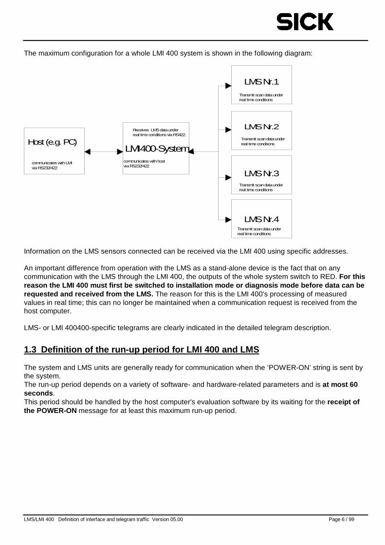
The maximum configuration for a whole LMI 400 system is shown in the following diagram:
Host (e.g. PC)LMI400-System
LMSNr.1
LMSNr.4
LMSNr.3
LMSNr.2
communicateswithhostviaRS232/422
Receives LMSdataunderreal timeconditionsviaRS422.
communicateswithLMIviaRS232/422
Transmit scandataunderreal timeconditions
Transmit scandataunderreal timeconditions
Transmit scandataunderreal timeconditions
Transmit scandataunderreal timeconditions
Information on the LMS sensors connected can be received via the LMI 400 using specific addresses.
An important difference from operation with the LMS as a stand-alone device is the fact that on anycommunication with the LMS through the LMI 400, the outputs of the whole system switch to RED. For thisreason the LMI 400 must first be switched to installation mode or diagnosis mode before data can berequested and received from the LMS. The reason for this is the LMI 400's processing of measuredvalues in real time; this can no longer be maintained when a communication request is received from thehost computer.
LMS- or LMI 400400-specific telegrams are clearly indicated in the detailed telegram description.
1.3 Definition of the run-up period for LMI 400 and LMS
The system and LMS units are generally ready for communication when the ‘POWER-ON’ string is sent bythe system.The run-up period depends on a variety of software- and hardware-related parameters and is at most 60seconds .This period should be handled by the host computer's evaluation software by its waiting for the receipt ofthe POWER-ON message for at least this maximum run-up period.
LMS/LMI 400 Definition of interface and telegram traffic Version 05.00 Page 7 / 99
1.4 Important interfaces for customer-specific evaluation software
There will inevitably be changes in our devices as a result of further development and improvement of oursystems. Fixed guidelines govern the implementation of such improvements. Functioal compatiblity isstrictly observed when making changes. In order to ensure that changes do not cause any conflicts withexisting and future versions, please read the following tips to avoid communication errors.
This section discusses important interfaces, time conditions and processes of significance for customer-specific evaluation systems.Ignoring these aspects can lead to incompatib ilities and start-up problems!
• Readiness for communication :The device is ready for communication after the complete transfer of the POWER-ON string has takenplace. Please note the variation in run-up times described in the preceding section. Duringsynchronisation operation with two scanners another 60 seconds may also be required for the transienteffect of the synchronisation process.
• Status byte informationStatus byte information varies and calls for correspondingly flexible handling. It is also recommended tointerrupt the evaluation of measured values only in the case of a fatal error.
• Address decodingAll LMS2xxx have the address 0 on delivery – also repaired and replacement devices.The devices answer with their individual address that corresponds, as standard, to the broadcastaddress 0. If the application requires no individual address it is not vitally necessary to check theaddress. The individual address has no effect on the functional behaviour of devices.
• Byte time intervalsOn transferring data packets from the LMS/LMI 400 to the host time periods of up to 14 ms betweentwo bytes must be taken into account depending on the LMS variant.
• Transmission of continuous measured valuesThe data flow may be interrupted by byte time intervals. Synchronisation should at least take place atSTX, an 8XH address, and when possible length and command, to rule out any erroneoussynchronisations. See also the example below for activating an operating mode for continuoustransmission.
• Change of operating modeA change of operating mode can take up to 3 seconds and corresponding time considerations shouldtake this into account. On changing to an operating mode with continuous data transmission thetransfer of data also takes place after an initial period of 2 – 4 seconds after the change has beenconfirmed, the period depending on the device in question.
LMS/LMI 400 Definition of interface and telegram traffic Version 05.00 Page 8 / 99
2 Definition of interface between LMS or LMI 400 and host computer2.1 Electrical interface:
The electrical interface can be formed in accordance with either an EIA RS-422-A standard or an EIARS-232-C standard.
2.2 Transfer and data format:
The baud rate of the LMS or LMI 400 is variable and can be set as follows:
• 500,000 baud• 38,400 baud• 19,200 baud• 9,600 baud.
The LMS and LMI 400 are delivered configured with a baud rate of 9,600 baud.The baud rate can be reconfigured via the interface. The corresponding telegram is described in greaterdetail in the telegram description entitled "20H: Change operating mode".
The standard baud rate after power has been switched on is 9,600 baud. However, the LMI 400 can beconfigured in such a way that the baud rate defined by the user remains set after power has beenswitched on. For further information please refer to the telegram description "Define permanent baudrate".
A byte of data consists of 1 start bit, 8 data bits, a parity bit with even parity or without parity (dependingon the variant) and 1 stop bit.
Neither LMI 400 nor LMS systems use a parity bit.
Pre-defined telegrams are available for communication with the host computer via the serial interface ofthe LMS / LMI 400. Data is transferred in binary format. Transfer is initiated by STX (02h). Data istransferred in INTEL data format, i.e. word transfer takes place with the lower address and the leastsignificant byte first and then bytes of higher significance and higher address.
The evaluation unit for data from the LMS or LMI 400 is referred to below as the HOST COMPUTER.
LMS/LMI 400 Definition of interface and telegram traffic Version 05.00 Page 9 / 99
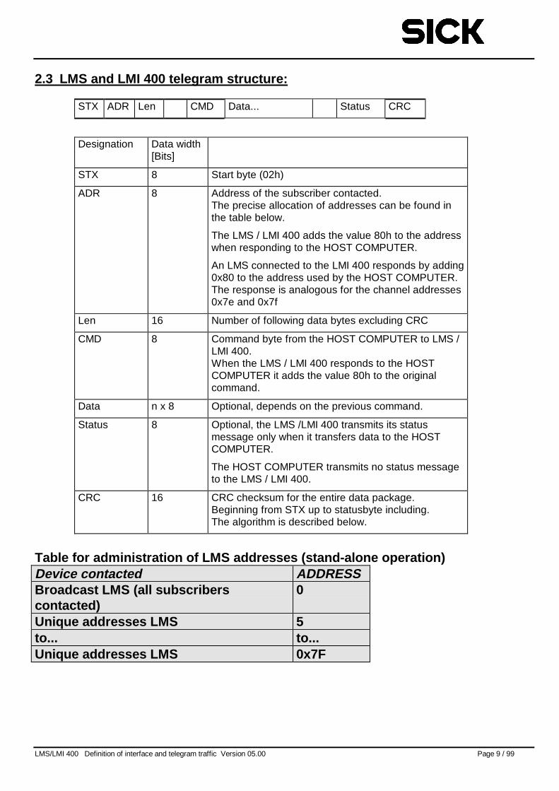
2.3 LMS and LMI 400 telegram structure:
STX ADR Len CMD Data... Status CRC
Designation Data width[Bits]
STX 8 Start byte (02h)
ADR 8 Address of the subscriber contacted.The precise allocation of addresses can be found inthe table below.
The LMS / LMI 400 adds the value 80h to the addresswhen responding to the HOST COMPUTER.
An LMS connected to the LMI 400 responds by adding0x80 to the address used by the HOST COMPUTER.The response is analogous for the channel addresses0x7e and 0x7f
Len 16 Number of following data bytes excluding CRC
CMD 8 Command byte from the HOST COMPUTER to LMS /LMI 400.When the LMS / LMI 400 responds to the HOSTCOMPUTER it adds the value 80h to the originalcommand.
Data n x 8 Optional, depends on the previous command.
Status 8 Optional, the LMS /LMI 400 transmits its statusmessage only when it transfers data to the HOSTCOMPUTER.
The HOST COMPUTER transmits no status messageto the LMS / LMI 400.
CRC 16 CRC checksum for the entire data package.Beginning from STX up to statusbyte including.The algorithm is described below.
Table for administration of LMS addresses (stand-alone operation)Device contacted ADDRESSBroadcast LMS (all subscriberscontacted)
0
Unique addresses LMS 5to... to...Unique addresses LMS 0x7F
LMS/LMI 400 Definition of interface and telegram traffic Version 05.00 Page 10 / 99
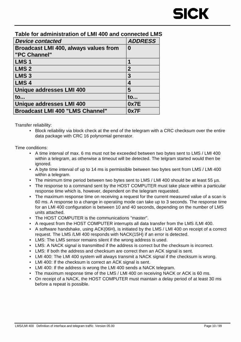
Table for administration of LMI 400 and connected LMSDevice contacted ADDRESSBroadcast LMI 400, always values from"PC Channel"
0
LMS 1 1LMS 2 2LMS 3 3LMS 4 4Unique addresses LMI 400 5to... to...Unique addresses LMI 400 0x7EBroadcast LMI 400 "LMS Channel" 0x7F
Transfer reliability:• Block reliability via block check at the end of the telegram with a CRC checksum over the entire
data package with CRC 16 polynomial generator.
Time conditions:• A time interval of max. 6 ms must not be exceeded between two bytes sent to LMS / LMI 400
within a telegram, as otherwise a timeout will be detected. The telgram started would then beignored.
• A byte time interval of up to 14 ms is permissible between two bytes sent from LMS / LMI 400within a telegram.
• The minimum time period between two bytes sent to LMS / LMI 400 should be at least 55 µs.• The response to a command sent by the HOST COMPUTER must take place within a particular
response time which is, however, dependent on the telegram requested.• The maximum response time on receiving a request for the current measured value of a scan is
60 ms. A response to a change in operating mode can take up to 3 seconds. The response timefor an LMI 400 configuration is between 10 and 40 seconds, depending on the number of LMSunits attached.
• The HOST COMPUTER is the communications "master".• A request from the HOST COMPUTER interrupts all data transfer from the LMS /LMI 400.• A software handshake, using ACK(06H), is initiated by the LMS / LMI 400 on receipt of a correct
request. The LMS /LMI 400 responds with NACK(15H) if an error is detected.• LMS: The LMS sensor remains silent if the wrong address is used.• LMS: A NACK signal is transmitted if the address is correct but the checksum is incorrect.• LMS: If both the address and checksum are correct then an ACK signal is sent.• LMI 400: The LMI 400 system will always transmit a NACK signal if the checksum is wrong.• LMI 400: If the checksum is correct an ACK signal is sent.• LMI 400: If the address is wrong the LMI 400 sends a NACK telegram.• The maximum response time of the LMS / LMI 400 on receiving NACK or ACK is 60 ms.• On receipt of a NACK, the HOST COMPUTER must maintain a delay period of at least 30 ms
before a repeat is possible.
LMS/LMI 400 Definition of interface and telegram traffic Version 05.00 Page 11 / 99
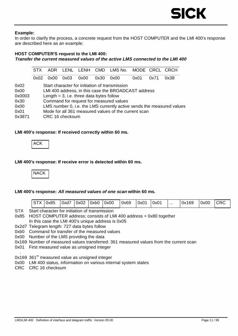
Example:In order to clarify the process, a concrete request from the HOST COMPUTER and the LMI 400's responseare described here as an example:
HOST COMPUTER'S request to the LMI 400:Transfer the current measured values of the active LMS connected to the LMI 400
STX ADR LENL LENH CMD LMS No. MODE CRCL CRCH
0x02 0x00 0x03 0x00 0x30 0x00 0x01 0x71 0x38
0x02 Start character for initiation of transmission0x00 LMI 400 address, in this case the BROADCAST address0x0003 Length = 3, i.e. three data bytes follow0x30 Command for request for measured values0x00 LMS number 0, i.e. the LMS currently active sends the measured values0x01 Mode for all 361 measured values of the current scan0x3871 CRC 16 checksum
LMI 400's res ponse: If r eceived correctly within 60 ms.
ACK
LMI 400's res ponse: If r eceive error is detected within 60 ms.
NACK
LMI 400's res ponse: All measured values of one scan within 60 ms.
STX 0x85 0xd7 0x02 0xb0 0x00 0x69 0x01 0x01 ... 0x169 0x00 CRC
STX Start character for initiation of transmission0x85 HOST COMPUTER address; consists of LMI 400 address + 0x80 together
In this case the LMI 400's unique address is 0x050x2d7 Telegram length: 727 data bytes follow0xb0 Command for transfer of the measured values0x00 Number of the LMS providing the data0x169 Number of measured values transferred: 361 measured values from the current scan0x01 First measured value as unsigned integer
.0x169 361st measured value as unsigned integer0x00 LMI 400 status, information on various internal system statesCRC CRC 16 checksum
LMS/LMI 400 Definition of interface and telegram traffic Version 05.00 Page 12 / 99
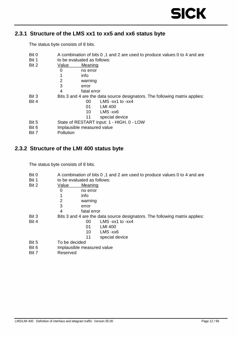
2.3.1 Structure of the LMS xx1 to xx5 and xx6 status byte
The status byte consists of 8 bits.
Bit 0 A combination of bits 0 ,1 and 2 are used to produce values 0 to 4 and areBit 1 to be evaluated as follows:Bit 2 Value Meaning
0 no error1 info2 warning3 error4 fatal error
Bit 3 Bits 3 and 4 are the data source designators. The following matrix applies:Bit 4 00 LMS -xx1 to -xx4
01 LMI 40010 LMS -xx611 special device
Bit 5 State of RESTART input: 1 - HIGH, 0 - LOWBit 6 Implausible measured valueBit 7 Pollution
2.3.2 Structure of the LMI 400 status byte
The status byte consists of 8 bits.
Bit 0 A combination of bits 0 ,1 and 2 are used to produce values 0 to 4 and areBit 1 to be evaluated as follows:Bit 2 Value Meaning
0 no error1 info2 warning3 error4 fatal error
Bit 3 Bits 3 and 4 are the data source designators. The following matrix applies:Bit 4 00 LMS -xx1 to -xx4
01 LMI 40010 LMS -xx611 special device
Bit 5 To be decidedBit 6 Implausible measured valueBit 7 Reserved
LMS/LMI 400 Definition of interface and telegram traffic Version 05.00 Page 13 / 99
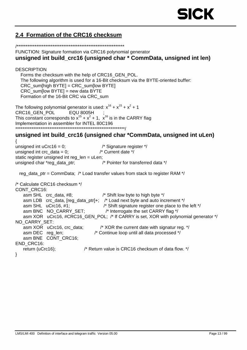
2.4 Formation of the CRC16 checksum
/************************************************************FUNCTION: Signature formation via CRC16 polynomial generatorunsigned int build_crc16 (unsigned char * CommData, unsigned int len)
DESCRIPTIONForms the checksum with the help of CRC16_GEN_POL.The following algorithm is used for a 16-Bit checksum via the BYTE-oriented buffer:CRC_sum[high BYTE] = CRC_sum[low BYTE]CRC_sum[low BYTE] = new data BYTEFormation of the 16-Bit CRC via CRC_sum
The following polynomial generator is used: x16 + x15 + x2 + 1CRC16_GEN_POL EQU 8005H ;This constant corresponds to x15 + x2 + 1, x16 is in the CARRY flagImplementation in assembler for INTEL 80C196*************************************************************/unsigned int build_crc16 (unsigned char *CommData, unsigned int uLen){unsigned int uCrc16 = 0; /* Signature register */unsigned int crc_data = 0; /* Current date */static register unsigned int reg_len = uLen;unsigned char *reg_data_ptr; /* Pointer for transferred data */
reg_data_ptr = CommData; /* Load transfer values from stack to register RAM */
/* Calculate CRC16 checksum */CONT_CRC16:
asm SHL crc_data, #8; /* Shift low byte to high byte */asm LDB crc_data, [reg_data_ptr]+; /* Load next byte and auto increment */asm SHL uCrc16, #1; /* Shift signature register one place to the left */asm BNC NO_CARRY_SET; /* Interrogate the set CARRY flag */asm XOR uCrc16, #CRC16_GEN_POL; /* If CARRY is set, XOR with polynomial generator */
NO_CARRY_SET:asm XOR uCrc16, crc_data; /* XOR the current date with signatur reg. */asm DEC reg_len; /* Continue loop until all data processed */asm BNE CONT_CRC16;
END_CRC16:return (uCrc16); /* Return value is CRC16 checksum of data flow. */
}
LMS/LMI 400 Definition of interface and telegram traffic Version 05.00 Page 14 / 99
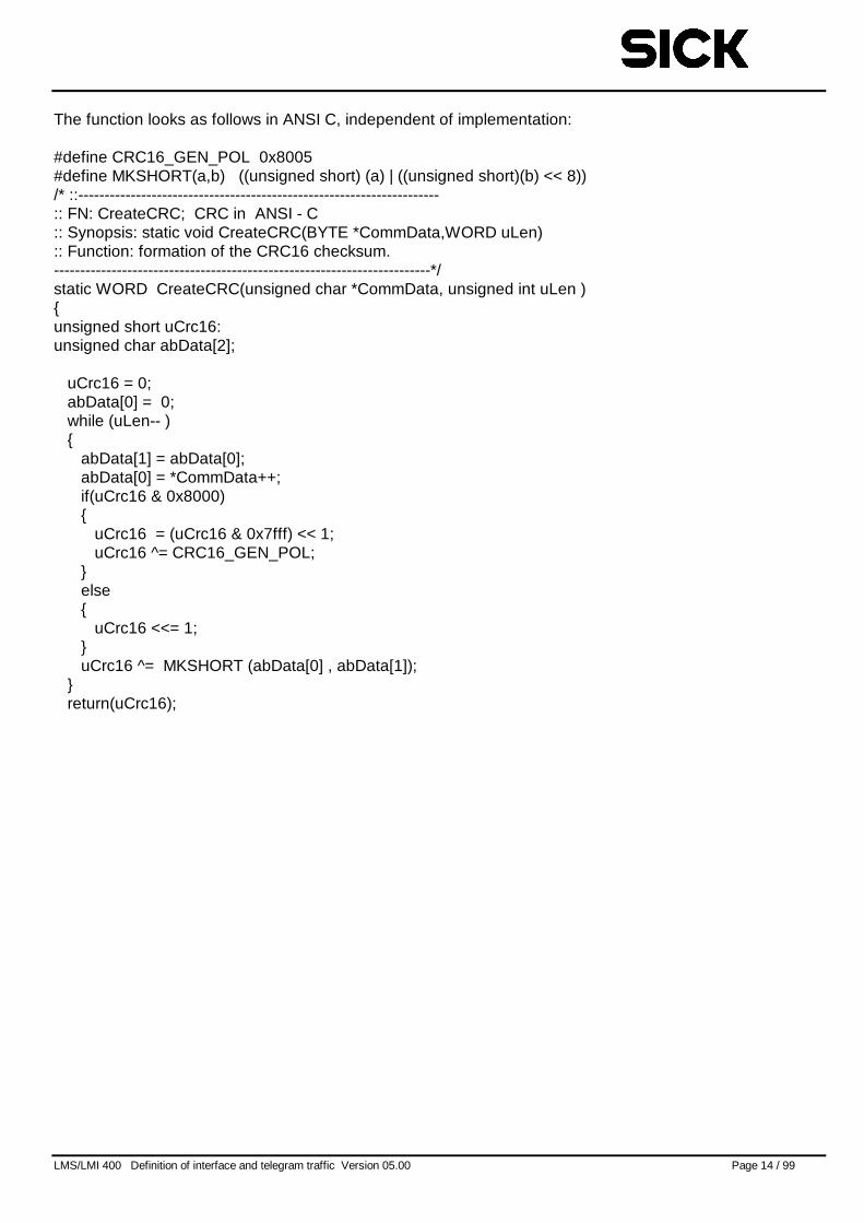
The function looks as follows in ANSI C, independent of implementation:
#define CRC16_GEN_POL 0x8005#define MKSHORT(a,b) ((unsigned short) (a) | ((unsigned short)(b) << 8))/* ::---------------------------------------------------------------------:: FN: CreateCRC; CRC in ANSI - C:: Synopsis: static void CreateCRC(BYTE *CommData,WORD uLen):: Function: formation of the CRC16 checksum.------------------------------------------------------------------------*/static WORD CreateCRC(unsigned char *CommData, unsigned int uLen ){unsigned short uCrc16:unsigned char abData[2];
uCrc16 = 0;abData[0] = 0;while (uLen-- ){
abData[1] = abData[0];abData[0] = *CommData++;if(uCrc16 & 0x8000){
uCrc16 = (uCrc16 & 0x7fff) << 1;uCrc16 ^= CRC16_GEN_POL;
}else{
uCrc16 <<= 1;}uCrc16 ^= MKSHORT (abData[0] , abData[1]);
}return(uCrc16);

LMS/LMI 400 Definition of interface and telegram traffic Version 05.00 Page 15 / 99
LMS/LMI 400 Definition of interface and telegram traffic Version 05.00 Page 16 / 99
3 Example of communication procedure for receiving measuredvalues from LMS or LMI 400
The most important procedures for receiving measured values from LMS or LMI 400 are described in thischapter. This example is principally of interest to those users who use their own evaluation platform andcannot employ the LMS/LMI 400 user software.
Details on the commands and telegrams used are, however, to be found in the following chapter"Description of available telegrams".
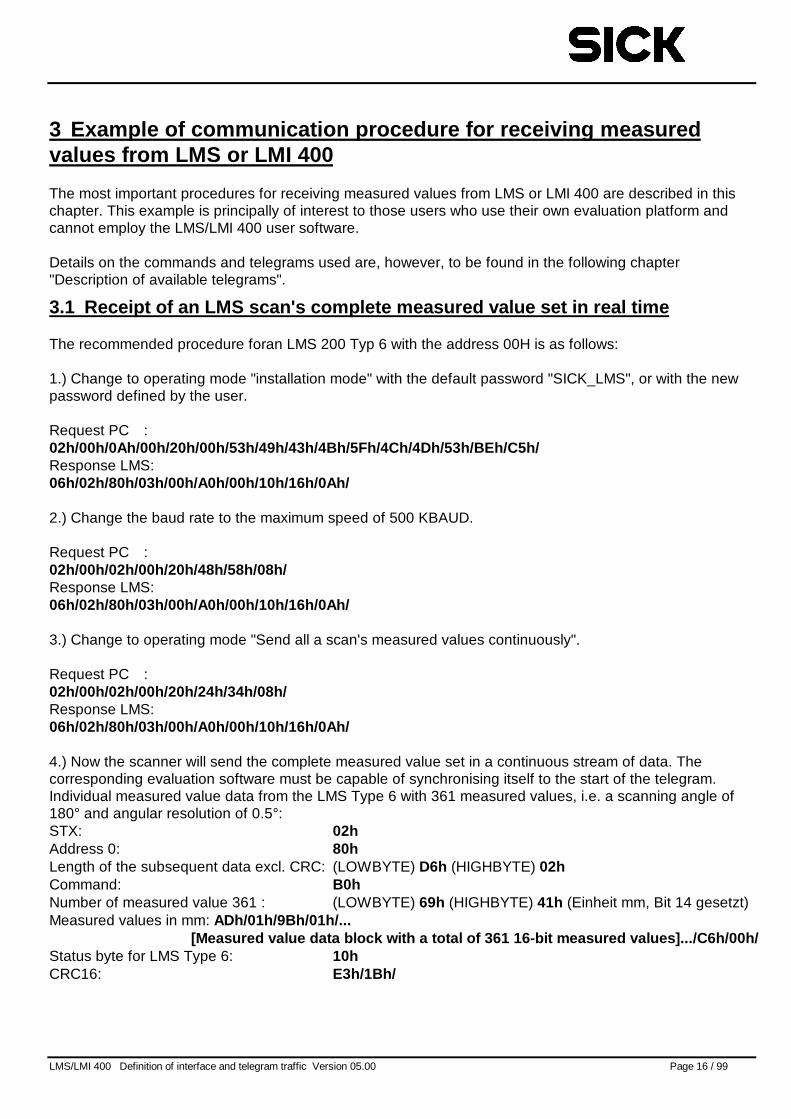
3.1 Receipt of an LMS scan's complete measured value set in real time
The recommended procedure foran LMS 200 Typ 6 with the address 00H is as follows:
1.) Change to operating mode "installation mode" with the default password "SICK_LMS", or with the newpassword defined by the user.
Request PC :02h/00h/0Ah/00h/20h/00h/53h/49h/43h/4Bh/5Fh/4Ch/4Dh/53h/BEh/C5h/Response LMS:06h/02h/80h/03h/00h/A0h/00h/10h/16h/0Ah/
2.) Change the baud rate to the maximum speed of 500 KBAUD.
Request PC :02h/00h/02h/00h/20h/48h/58h/08h/Response LMS:06h/02h/80h/03h/00h/A0h/00h/10h/16h/0Ah/
3.) Change to operating mode "Send all a scan's measured values continuously".
Request PC :02h/00h/02h/00h/20h/24h/34h/08h/Response LMS:06h/02h/80h/03h/00h/A0h/00h/10h/16h/0Ah/
4.) Now the scanner will send the complete measured value set in a continuous stream of data. Thecorresponding evaluation software must be capable of synchronising itself to the start of the telegram.Individual measured value data from the LMS Type 6 with 361 measured values, i.e. a scanning angle of180° and angular resolution of 0.5°:STX: 02hAddress 0: 80hLength of the subsequent data excl. CRC: (LOWBYTE) D6h (HIGHBYTE) 02hCommand: B0hNumber of measured value 361 : (LOWBYTE) 69h (HIGHBYTE) 41h (Einheit mm, Bit 14 gesetzt)Measured values in mm: ADh/01h/9Bh/01h/...
[Measured value data block with a total of 361 16-bit measured values].../C6h/00h/Status byte for LMS Type 6: 10hCRC16: E3h/1Bh/
LMS/LMI 400 Definition of interface and telegram traffic Version 05.00 Page 17 / 99
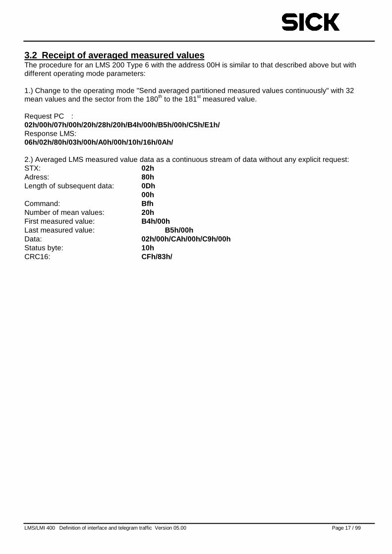
3.2 Receipt of averaged measured valuesThe procedure for an LMS 200 Type 6 with the address 00H is similar to that described above but withdifferent operating mode parameters:
1.) Change to the operating mode "Send averaged partitioned measured values continuously" with 32mean values and the sector from the 180th to the 181st measured value.
Request PC :02h/00h/07h/00h/20h/28h/20h/B4h/00h/B5h/00h/C5h/E1h/Response LMS:06h/02h/80h/03h/00h/A0h/00h/10h/16h/0Ah/
2.) Averaged LMS measured value data as a continuous stream of data without any explicit request:STX: 02hAdress: 80hLength of subsequent data: 0Dh
00hCommand: BfhNumber of mean values: 20hFirst measured value: B4h/00hLast measured value: B5h/00hData: 02h/00h/CAh/00h/C9h/00hStatus byte: 10hCRC16: CFh/83h/
LMS/LMI 400 Definition of interface and telegram traffic Version 05.00 Page 18 / 99
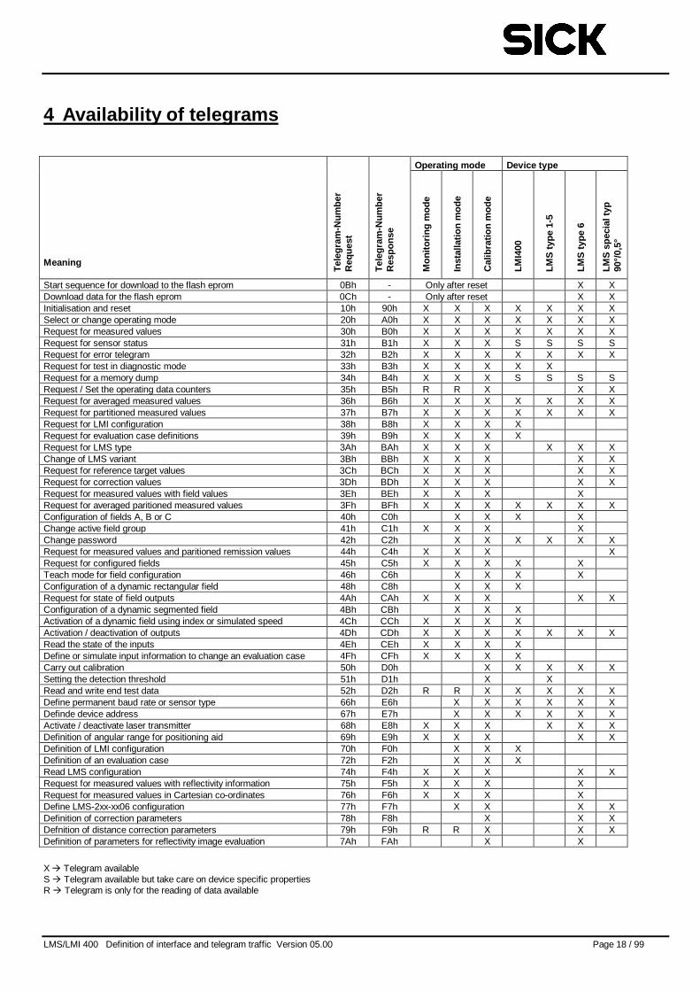
4 Availability of telegrams
Operating mode Device type
Meaning
Tel
egra
m-N
umbe
rR
eque
st
Tel
egra
m-N
umbe
rR
espo
nse
Mon
itorin
gm
ode
Inst
alla
tion
mod
e
Cal
ibra
tion
mod
e
LMI4
00
LMS
type
1-5
LMS
type
6
LMS
spec
ialt
yp90
°/0,
5°
Start sequence for download to the flash eprom 0Bh - Only after reset X XDownload data for the flash eprom 0Ch - Only after reset X XInitialisation and reset 10h 90h X X X X X X XSelect or change operating mode 20h A0h X X X X X X XRequest for measured values 30h B0h X X X X X X XRequest for sensor status 31h B1h X X X S S S SRequest for error telegram 32h B2h X X X X X X XRequest for test in diagnostic mode 33h B3h X X X X XRequest for a memory dump 34h B4h X X X S S S SRequest / Set the operating data counters 35h B5h R R X X XRequest for averaged measured values 36h B6h X X X X X X XRequest for partitioned measured values 37h B7h X X X X X X XRequest for LMI configuration 38h B8h X X X XRequest for evaluation case definitions 39h B9h X X X XRequest for LMS type 3Ah BAh X X X X X XChange of LMS variant 3Bh BBh X X X X XRequest for reference target values 3Ch BCh X X X X XRequest for correction values 3Dh BDh X X X X XRequest for measured values with field values 3Eh BEh X X X XRequest for averaged paritioned measured values 3Fh BFh X X X X X X XConfiguration of fields A, B or C 40h C0h X X X XChange active field group 41h C1h X X X XChange password 42h C2h X X X X X XRequest for measured values and paritioned remission values 44h C4h X X X XRequest for configured fields 45h C5h X X X X XTeach mode for field configuration 46h C6h X X X XConfiguration of a dynamic rectangular field 48h C8h X X XRequest for state of field outputs 4Ah CAh X X X X XConfiguration of a dynamic segmented field 4Bh CBh X X XActivation of a dynamic field using index or simulated speed 4Ch CCh X X X XActivation / deactivation of outputs 4Dh CDh X X X X X X XRead the state of the inputs 4Eh CEh X X X XDefine or simulate input information to change an evaluation case 4Fh CFh X X X XCarry out calibration 50h D0h X X X X XSetting the detection threshold 51h D1h X XRead and write end test data 52h D2h R R X X X X XDefine permanent baud rate or sensor type 66h E6h X X X X X XDefinde device address 67h E7h X X X X X XActivate / deactivate laser transmitter 68h E8h X X X X X XDefinition of angular range for positioning aid 69h E9h X X X X XDefinition of LMI configuration 70h F0h X X XDefinition of an evaluation case 72h F2h X X XRead LMS configuration 74h F4h X X X X XRequest for measured values with reflectivity information 75h F5h X X X XRequest for measured values in Cartesian co-ordinates 76h F6h X X X XDefine LMS-2xx-xx06 configuration 77h F7h X X X XDefinition of correction parameters 78h F8h X X XDefnition of distance correction parameters 79h F9h R R X X XDefinition of parameters for reflectivity image evaluation 7Ah FAh X X
X � Telegram availableS � Telegram available but take care on device specific propertiesR � Telegram is only for the reading of data available
LMS/LMI 400 Definition of interface and telegram traffic Version 05.00 Page 19 / 99
5 Description of available telegrams
5.1 Data direction: Host computer -> LMS / LMI 400
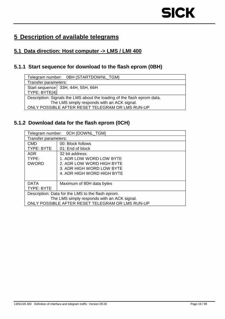
5.1.1 Start sequence for download to the flash eprom (0BH)
Telegram number: 0BH (STARTDOWNL_TGM)Transfer parameters:Start sequenceTYPE: BYTE[4]
33H, 44H, 55H, 66H
Description: Signals the LMS about the loading of the flash eprom data.The LMS simply responds with an ACK signal.
ONLY POSSIBLE AFTER RESET TELEGRAM OR LMS RUN-UP
5.1.2 Download data for the flash eprom (0CH)
Telegram number: 0CH (DOWNL_TGM)Transfer parameters:CMDTYPE: BYTE
00: Block follows01: End of block
ADRTYPE:DWORD
32 bit address:1. ADR LOW WORD LOW BYTE2. ADR LOW WORD HIGH BYTE3. ADR HIGH WORD LOW BYTE4. ADR HIGH WORD HIGH BYTE
DATATYPE: BYTE
Maximum of 80H data bytes
Description: Data for the LMS to the flash eprom.The LMS simply responds with an ACK signal.
ONLY POSSIBLE AFTER RESET TELEGRAM OR LMS RUN-UP
LMS/LMI 400 Definition of interface and telegram traffic Version 05.00 Page 20 / 99
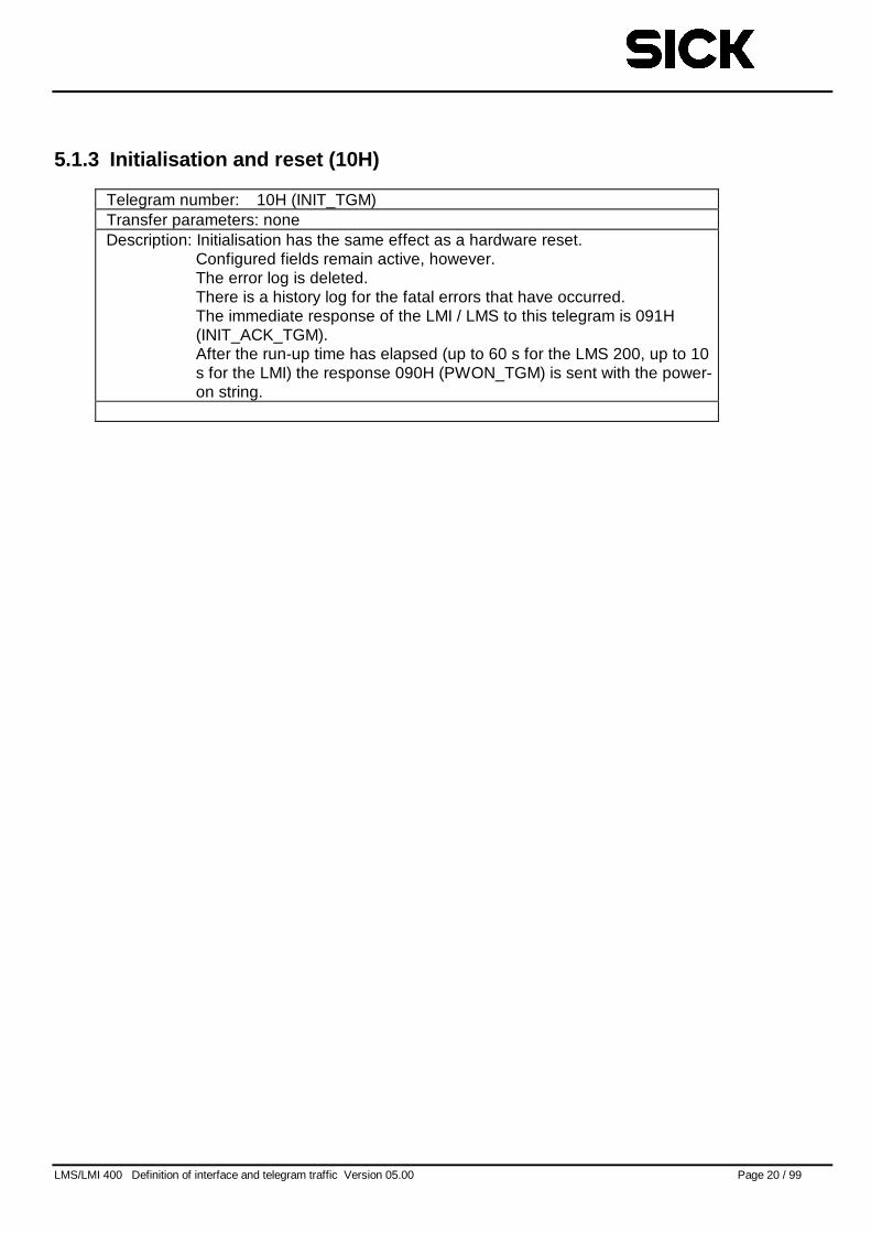
5.1.3 Initialisation and reset (10H)
Telegram number: 10H (INIT_TGM)Transfer parameters: noneDescription: Initialisation has the same effect as a hardware reset.
Configured fields remain active, however.The error log is deleted.There is a history log for the fatal errors that have occurred.The immediate response of the LMI / LMS to this telegram is 091H(INIT_ACK_TGM).After the run-up time has elapsed (up to 60 s for the LMS 200, up to 10s for the LMI) the response 090H (PWON_TGM) is sent with the power-on string.
LMS/LMI 400 Definition of interface and telegram traffic Version 05.00 Page 21 / 99
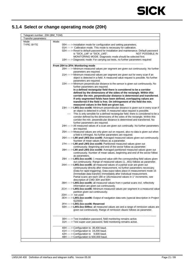
5.1.4 Select or change operating mode (20H)
Telegram number: 20H (BM_TGM)Transfer parameters:ModeTYPE: BYTE
Mode:00H ---- > Installation mode for configuration and setting parameters.01H ---- > Calibration mode. This mode is necessary for calibration.02H ---- > Reset to default password for installation and maintenance. Default password
is "SICK_LMI" or "SICK_LMS". NOT POSSIBLE INMONITORING MODE. Diagnostic mode should be selected first.
10H ---- > Diagnostic mode: For carrying out tests, no further parameters required_________________________________________________________________From 20H to 2FH: Monitoring mode
20H ---- > Minimum measured values per segment are given out continuously. No furtherparameters are required.
21H ---- > Minimum measured values per segment are given out for every scan if anobject is detected in a field. A measured value request is possible. No furtherparameters are required.
22H ---- > Minimum perpendicular distance to the sensor is given out continuously. Nofurther parameters are required.In a defined rectangular field there is considered to be a corridordefined by the dimensions of the sides of the rectangle. Within thiscorridor the min. perpendicular distance is determined and transferred.If only segmented fields have been defined, overlapping values aretransferred if the field is free. On infringement of the field the min.measured values in the field are given out.
23H ---- > LMS-2xx-xxx06: Minimum perpendicular distance is given out in every scan ifan object is detected in a field. A measured value request is possible.
---- This is only sensible for a defined rectangular field; there is considered to be acorridor defined by the dimensions of the sides of the rectangle. Within thiscorridor the min. perpendicular distance is determined and transferred. Nofurther parameters are required.
24H ---- > All measured values of a scan are given out continually. No further parametersare required.
25H ---- > Measured values are only given out on request, also no data is given out whena field is infringed. No further parameters are required.
26H ---- > LMI and LMS-2xx-xxx06: Averaged measured values given out continuously.Number of mean values follows as a parameter.
27H ---- > LMI and LMS-2xx-xxx06: Partitioned measured values given outcontinuously. Beginning and end of the sector follow as parameter.
28H ---- > LMI and LMS-2xx-xxx06: Averaged partitioned measured values given outcontinuously. Number of mean values, beginning and end of the sector followas parameters.
29H --- > LMS-2xx-xxx06: 1 measured value with the corresponding field values givenout continuously. Range of measured values (1...401) follows as parameter.
2AH ---- > LMS-2xx-xxx06: all measured values of a partial scan are given outcontinuously directly after measurement, no further parameters necessary.(Data for rapid triggering). Data ouput takes place in measurement mode 15(Immediate data transfer) immediately after individual measurement.Partial scans are each 180 or 181measured values in 1° increments, seedescription of CMD 30H and B0H
2BH ---- > LMS-2xx-xxx06: all measured values from n partial scans incl. reflectivityinformation are given out continuously.
2CH ---- > LMS-2xx-xxx06: Minimum measured values per segment in a measured valuepartition given out continuously.
2DH ---- > not used2EH ---- > LMS-2xx-xxx06: Output of navigation data sets (special description in Project
IQ2000)2FH ---- > LMS-2xx-xxx06: Reserved50H ---- > LMS-2xx-S09xx: all measured values are and a range of remission values are
given out continuously. Range of remission vlaues follows as parameter.
--------------------------------------------------------------------------------------------------------------------–––-30H ---- > Test installation password, field monitoring remains active.31H ---- > Test super-user password, field monitoring remains active.
_________________________________________________________________________40H ---- > Configuration to 38,400 baud.41H ---- > Configuration to 19,200 baud.42H ---- > Configuration to 9,600 baud.48H ---- > Configuration to 500,000 baud.
LMS/LMI 400 Definition of interface and telegram traffic Version 05.00 Page 22 / 99
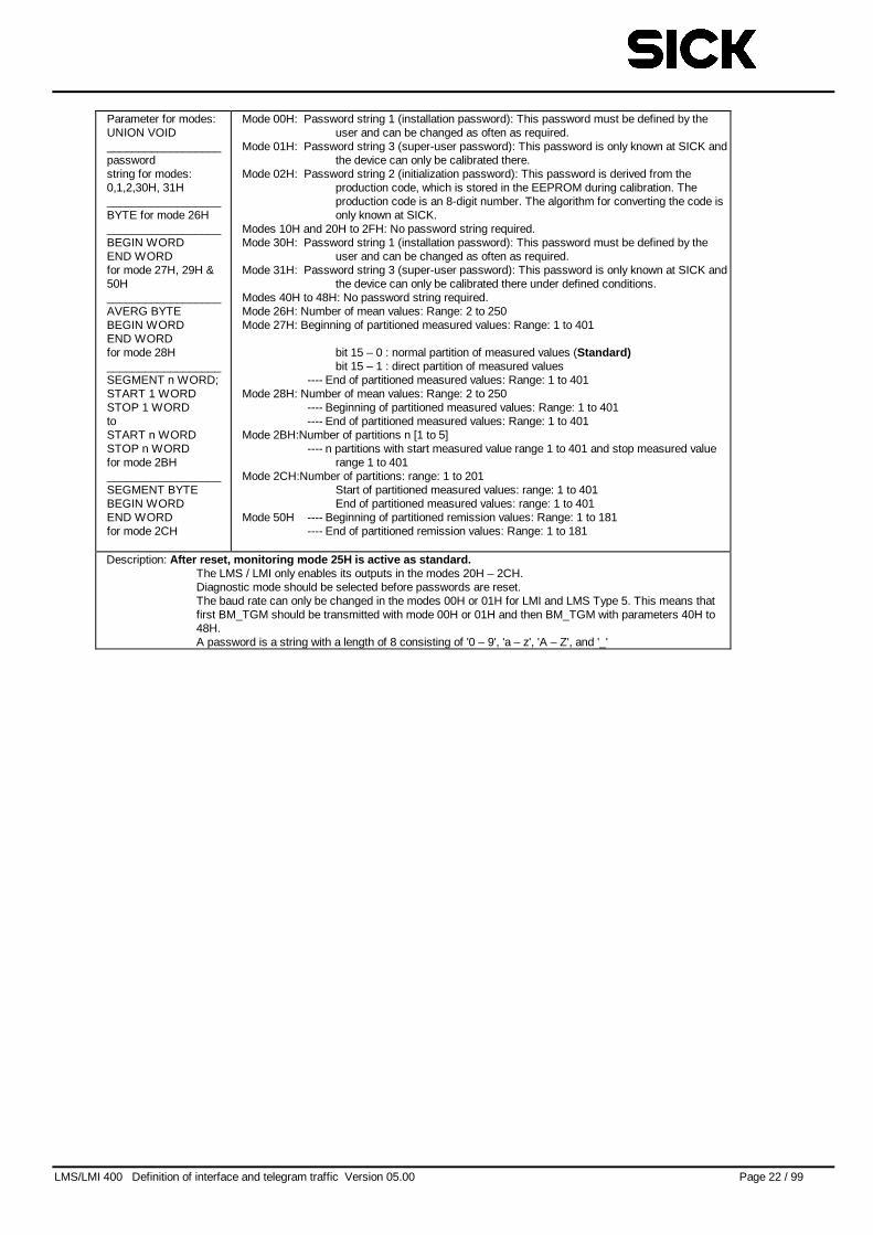
Parameter for modes:UNION VOID__________________passwordstring for modes:0,1,2,30H, 31H__________________BYTE for mode 26H__________________BEGIN WORDEND WORDfor mode 27H, 29H &50H__________________AVERG BYTEBEGIN WORDEND WORDfor mode 28H__________________SEGMENT n WORD;START 1 WORDSTOP 1 WORDtoSTART n WORDSTOP n WORDfor mode 2BH__________________SEGMENT BYTEBEGIN WORDEND WORDfor mode 2CH
Mode 00H: Password string 1 (installation password): This password must be defined by theuser and can be changed as often as required.
Mode 01H: Password string 3 (super-user password): This password is only known at SICK andthe device can only be calibrated there.
Mode 02H: Password string 2 (initialization password): This password is derived from theproduction code, which is stored in the EEPROM during calibration. Theproduction code is an 8-digit number. The algorithm for converting the code isonly known at SICK.
Modes 10H and 20H to 2FH: No password string required.Mode 30H: Password string 1 (installation password): This password must be defined by the
user and can be changed as often as required.Mode 31H: Password string 3 (super-user password): This password is only known at SICK and
the device can only be calibrated there under defined conditions.Modes 40H to 48H: No password string required.Mode 26H: Number of mean values: Range: 2 to 250Mode 27H: Beginning of partitioned measured values: Range: 1 to 401
bit 15 – 0 : normal partition of measured values (Standard)bit 15 – 1 : direct partition of measured values
---- End of partitioned measured values: Range: 1 to 401Mode 28H: Number of mean values: Range: 2 to 250
---- Beginning of partitioned measured values: Range: 1 to 401---- End of partitioned measured values: Range: 1 to 401
Mode 2BH:Number of partitions n [1 to 5]---- n partitions with start measured value range 1 to 401 and stop measured value
range 1 to 401Mode 2CH:Number of partitions: range: 1 to 201
Start of partitioned measured values: range: 1 to 401End of partitioned measured values: range: 1 to 401
Mode 50H ---- Beginning of partitioned remission values: Range: 1 to 181---- End of partitioned remission values: Range: 1 to 181
Description: After reset, monitoring mode 25H is active as standard.The LMS / LMI only enables its outputs in the modes 20H – 2CH.Diagnostic mode should be selected before passwords are reset.The baud rate can only be changed in the modes 00H or 01H for LMI and LMS Type 5. This means thatfirst BM_TGM should be transmitted with mode 00H or 01H and then BM_TGM with parameters 40H to48H.A password is a string with a length of 8 consisting of '0 – 9', 'a – z', 'A – Z', and '_'
LMS/LMI 400 Definition of interface and telegram traffic Version 05.00 Page 23 / 99
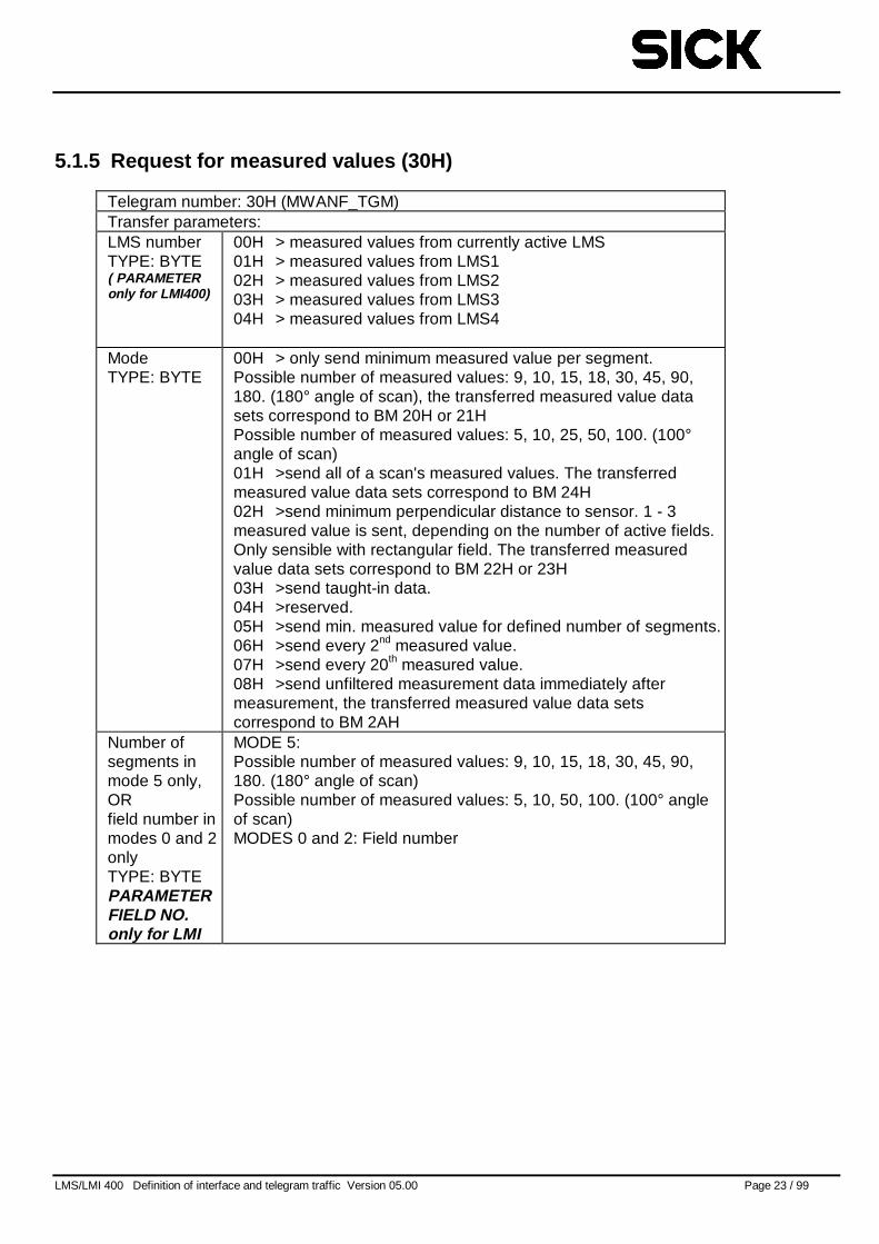
5.1.5 Request for measured values (30H)
Telegram number: 30H (MWANF_TGM)Transfer parameters:LMS numberTYPE: BYTE( PARAMETERonly for LMI400)
00H > measured values from currently active LMS01H > measured values from LMS102H > measured values from LMS203H > measured values from LMS304H > measured values from LMS4
ModeTYPE: BYTE
00H > only send minimum measured value per segment.Possible number of measured values: 9, 10, 15, 18, 30, 45, 90,180. (180° angle of scan), the transferred measured value datasets correspond to BM 20H or 21HPossible number of measured values: 5, 10, 25, 50, 100. (100°angle of scan)01H >send all of a scan's measured values. The transferredmeasured value data sets correspond to BM 24H02H >send minimum perpendicular distance to sensor. 1 - 3measured value is sent, depending on the number of active fields.Only sensible with rectangular field. The transferred measuredvalue data sets correspond to BM 22H or 23H03H >send taught-in data.04H >reserved.05H >send min. measured value for defined number of segments.06H >send every 2nd measured value.07H >send every 20th measured value.08H >send unfiltered measurement data immediately aftermeasurement, the transferred measured value data setscorrespond to BM 2AH
Number ofsegments inmode 5 only,ORfield number inmodes 0 and 2onlyTYPE: BYTEPARAMETERFIELD NO.only for LMI
MODE 5:Possible number of measured values: 9, 10, 15, 18, 30, 45, 90,180. (180° angle of scan)Possible number of measured values: 5, 10, 50, 100. (100° angleof scan)MODES 0 and 2: Field number
LMS/LMI 400 Definition of interface and telegram traffic Version 05.00 Page 24 / 99
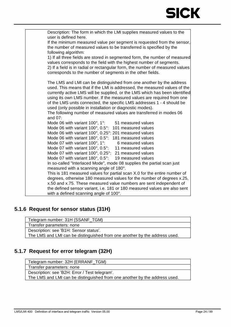
Description: The form in which the LMI supplies measured values to theuser is defined here.If the minimum measured value per segment is requested from the sensor,the number of measured values to be transferred is specified by thefollowing algorithm:1) If all three fields are stored in segmented form, the number of measuredvalues corresponds to the field with the highest number of segments.2) If a field is in radial or rectangular form, the number of measured valuescorresponds to the number of segments in the other fields.
The LMS and LMI can be distinguished from one another by the addressused. This means that if the LMI is addressed, the measured values of thecurrently active LMS will be supplied, or the LMS which has been identifiedusing its own LMS number. If the measured values are required from oneof the LMS units connected, the specific LMS addresses 1 - 4 should beused (only possible in installation or diagnostic modes).The following number of measured values are transferred in modes 06and 07:Mode 06 with variant 100°, 1°: 51 measured valuesMode 06 with variant 100°, 0.5°: 101 measured valuesMode 06 with variant 100°, 0.25°: 201 measured valuesMode 06 with variant 180°, 0.5°: 181 measured valuesMode 07 with variant 100°, 1°: 6 measured valuesMode 07 with variant 100°, 0.5°: 11 measured valuesMode 07 with variant 100°, 0.25°: 21 measured valuesMode 07 with variant 180°, 0.5°: 19 measured valuesIn so-called "Interlaced Mode", mode 08 supplies the partial scan justmeasured with a scanning angle of 180°.This is 181 measured values for partial scan X.0 for the entire number ofdegrees, otherwise 180 measured values for the number of degrees x.25,x.50 and x.75. These measured value numbers are sent independent ofthe defined sensor variant, i.e. 181 or 180 measured values are also sentwith a defined scanning angle of 100°.
5.1.6 Request for sensor status (31H)
Telegram number: 31H (SSANF_TGM)Transfer parameters: noneDescription: see 'B1H: Sensor status'.The LMS and LMI can be distinguished from one another by the address used.
5.1.7 Request for error telegram (32H)
Telegram number: 32H (ERRANF_TGM)Transfer parameters: noneDescription: see 'B2H: Error / Test telegram'.The LMS and LMI can be distinguished from one another by the address used.
LMS/LMI 400 Definition of interface and telegram traffic Version 05.00 Page 25 / 99
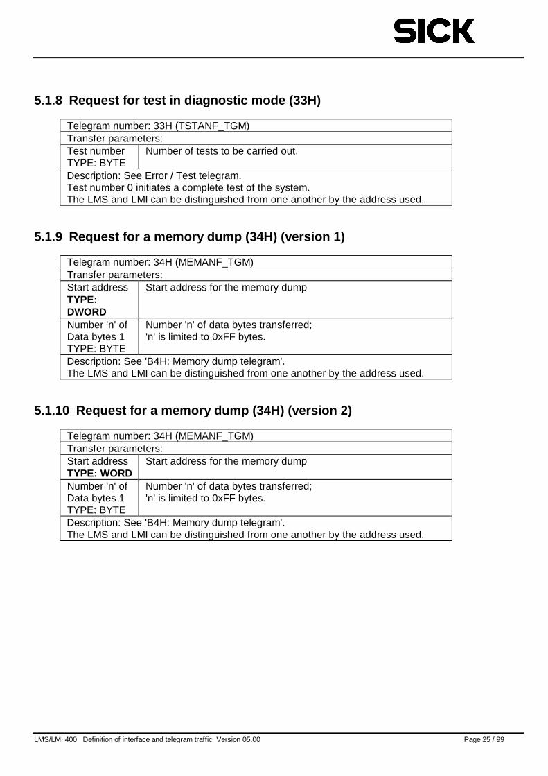
5.1.8 Request for test in diagnostic mode (33H)
Telegram number: 33H (TSTANF_TGM)Transfer parameters:Test numberTYPE: BYTE
Number of tests to be carried out.
Description: See Error / Test telegram.Test number 0 initiates a complete test of the system.The LMS and LMI can be distinguished from one another by the address used.
5.1.9 Request for a memory dump (34H) (version 1)
Telegram number: 34H (MEMANF_TGM)Transfer parameters:Start addressTYPE:DWORD
Start address for the memory dump
Number 'n' ofData bytes 1TYPE: BYTE
Number 'n' of data bytes transferred;'n' is limited to 0xFF bytes.
Description: See 'B4H: Memory dump telegram'.The LMS and LMI can be distinguished from one another by the address used.
5.1.10 Request for a memory dump (34H) (version 2)
Telegram number: 34H (MEMANF_TGM)Transfer parameters:Start addressTYPE: WORD
Start address for the memory dump
Number 'n' ofData bytes 1TYPE: BYTE
Number 'n' of data bytes transferred;'n' is limited to 0xFF bytes.
Description: See 'B4H: Memory dump telegram'.The LMS and LMI can be distinguished from one another by the address used.

LMS/LMI 400 Definition of interface and telegram traffic Version 05.00 Page 26 / 99
5.1.11 Request / set operating data counters (35H)
Telegram number: 35H (OP_COUNTER_TGM)Transfer parameters:ModeTYPE: WORD
0 Read operating data counters1 Set operating data counters (only in Calibration Mode)Data if mode „Set“
OperationHourTYPE: WORD
Value of operating hours countersMinimum: 0 Maximum: 60000It’s not possible to set odd values because of the internal resolutionof 2 hours. Odd values were rounded down.
SwitchOnTYPE: WORD
Value of switch on counterMinimum: 0 Maximum: 10000
Description: Operating data counters are requested. Also a setting of these countersis possible. In the mode read there were no more parameters expected.
LMS/LMI 400 Definition of interface and telegram traffic Version 05.00 Page 27 / 99
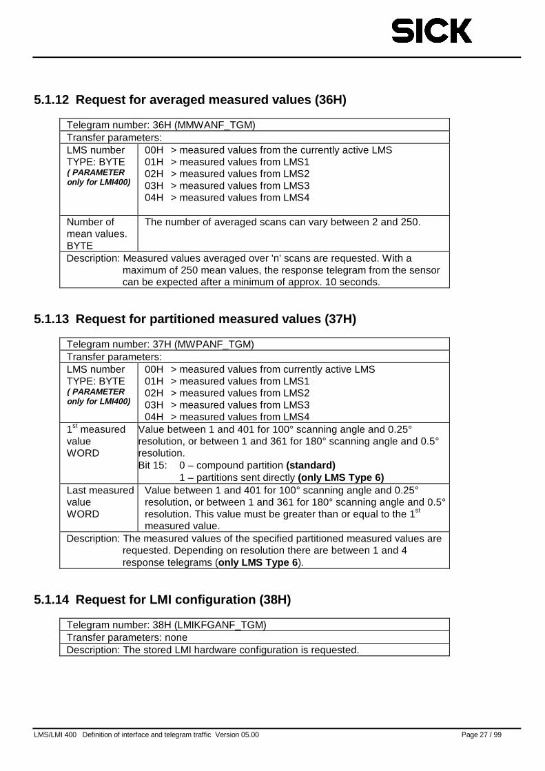
5.1.12 Request for averaged measured values (36H)
Telegram number: 36H (MMWANF_TGM)Transfer parameters:LMS numberTYPE: BYTE( PARAMETERonly for LMI400)
00H > measured values from the currently active LMS01H > measured values from LMS102H > measured values from LMS203H > measured values from LMS304H > measured values from LMS4
Number ofmean values.BYTE
The number of averaged scans can vary between 2 and 250.
Description: Measured values averaged over 'n' scans are requested. With amaximum of 250 mean values, the response telegram from the sensorcan be expected after a minimum of approx. 10 seconds.
5.1.13 Request for partitioned measured values (37H)
Telegram number: 37H (MWPANF_TGM)Transfer parameters:LMS numberTYPE: BYTE( PARAMETERonly for LMI400)
00H > measured values from currently active LMS01H > measured values from LMS102H > measured values from LMS203H > measured values from LMS304H > measured values from LMS4
1st measuredvalueWORD
Value between 1 and 401 for 100° scanning angle and 0.25°resolution, or between 1 and 361 for 180° scanning angle and 0.5°resolution.Bit 15: 0 – compound partition (standard)
1 – partitions sent directly (only LMS Type 6)Last measuredvalueWORD
Value between 1 and 401 for 100° scanning angle and 0.25°resolution, or between 1 and 361 for 180° scanning angle and 0.5°resolution. This value must be greater than or equal to the 1st
measured value.Description: The measured values of the specified partitioned measured values are
requested. Depending on resolution there are between 1 and 4response telegrams (only LMS Type 6 ).
5.1.14 Request for LMI configuration (38H)
Telegram number: 38H (LMIKFGANF_TGM)Transfer parameters: noneDescription: The stored LMI hardware configuration is requested.
LMS/LMI 400 Definition of interface and telegram traffic Version 05.00 Page 28 / 99
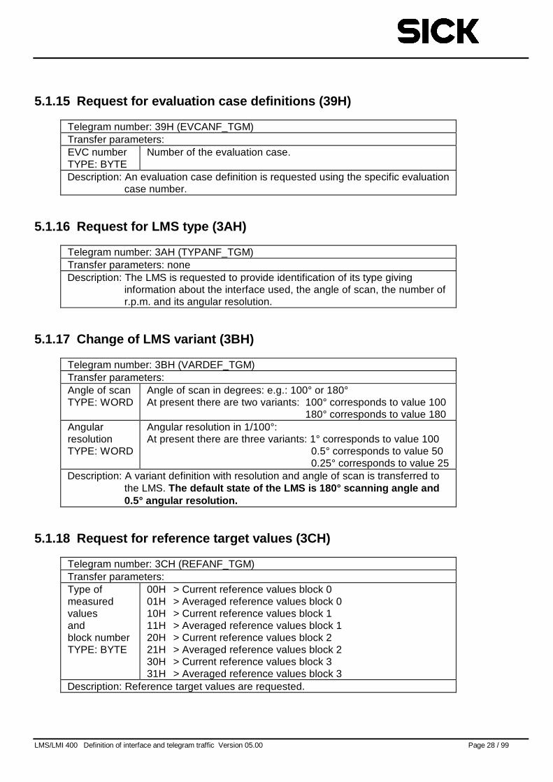
5.1.15 Request for evaluation case definitions (39H)
Telegram number: 39H (EVCANF_TGM)Transfer parameters:EVC numberTYPE: BYTE
Number of the evaluation case.
Description: An evaluation case definition is requested using the specific evaluationcase number.
5.1.16 Request for LMS type (3AH)
Telegram number: 3AH (TYPANF_TGM)Transfer parameters: noneDescription: The LMS is requested to provide identification of its type giving
information about the interface used, the angle of scan, the number ofr.p.m. and its angular resolution.
5.1.17 Change of LMS variant (3BH)
Telegram number: 3BH (VARDEF_TGM)Transfer parameters:Angle of scanTYPE: WORD
Angle of scan in degrees: e.g.: 100° or 180°At present there are two variants: 100° corresponds to value 100
180° corresponds to value 180AngularresolutionTYPE: WORD
Angular resolution in 1/100°:At present there are three variants: 1° corresponds to value 100
0.5° corresponds to value 500.25° corresponds to value 25
Description: A variant definition with resolution and angle of scan is transferred tothe LMS. The default state of the LMS is 180° scanning angle and0.5° angular resolution.
5.1.18 Request for reference target values (3CH)
Telegram number: 3CH (REFANF_TGM)Transfer parameters:Type ofmeasuredvaluesandblock numberTYPE: BYTE
00H > Current reference values block 001H > Averaged reference values block 010H > Current reference values block 111H > Averaged reference values block 120H > Current reference values block 221H > Averaged reference values block 230H > Current reference values block 331H > Averaged reference values block 3
Description: Reference target values are requested.
LMS/LMI 400 Definition of interface and telegram traffic Version 05.00 Page 29 / 99
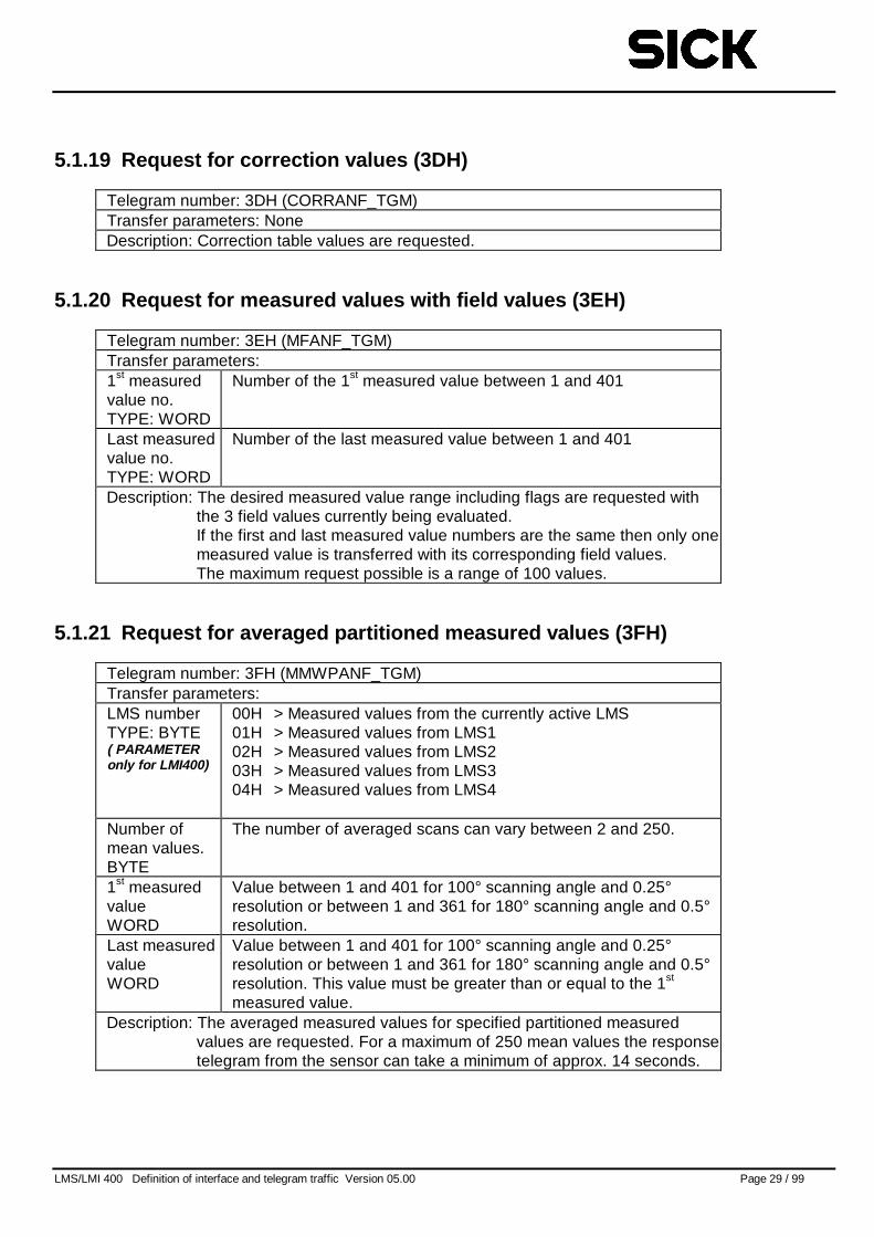
5.1.19 Request for correction values (3DH)
Telegram number: 3DH (CORRANF_TGM)Transfer parameters: NoneDescription: Correction table values are requested.
5.1.20 Request for measured values with field values (3EH)
Telegram number: 3EH (MFANF_TGM)Transfer parameters:1st measuredvalue no.TYPE: WORD
Number of the 1st measured value between 1 and 401
Last measuredvalue no.TYPE: WORD
Number of the last measured value between 1 and 401
Description: The desired measured value range including flags are requested withthe 3 field values currently being evaluated.If the first and last measured value numbers are the same then only onemeasured value is transferred with its corresponding field values.The maximum request possible is a range of 100 values.
5.1.21 Request for averaged partitioned measured values (3FH)
Telegram number: 3FH (MMWPANF_TGM)Transfer parameters:LMS numberTYPE: BYTE( PARAMETERonly for LMI400)
00H > Measured values from the currently active LMS01H > Measured values from LMS102H > Measured values from LMS203H > Measured values from LMS304H > Measured values from LMS4
Number ofmean values.BYTE
The number of averaged scans can vary between 2 and 250.
1st measuredvalueWORD
Value between 1 and 401 for 100° scanning angle and 0.25°resolution or between 1 and 361 for 180° scanning angle and 0.5°resolution.
Last measuredvalueWORD
Value between 1 and 401 for 100° scanning angle and 0.25°resolution or between 1 and 361 for 180° scanning angle and 0.5°resolution. This value must be greater than or equal to the 1st
measured value.Description: The averaged measured values for specified partitioned measured
values are requested. For a maximum of 250 mean values the responsetelegram from the sensor can take a minimum of approx. 14 seconds.
LMS/LMI 400 Definition of interface and telegram traffic Version 05.00 Page 30 / 99
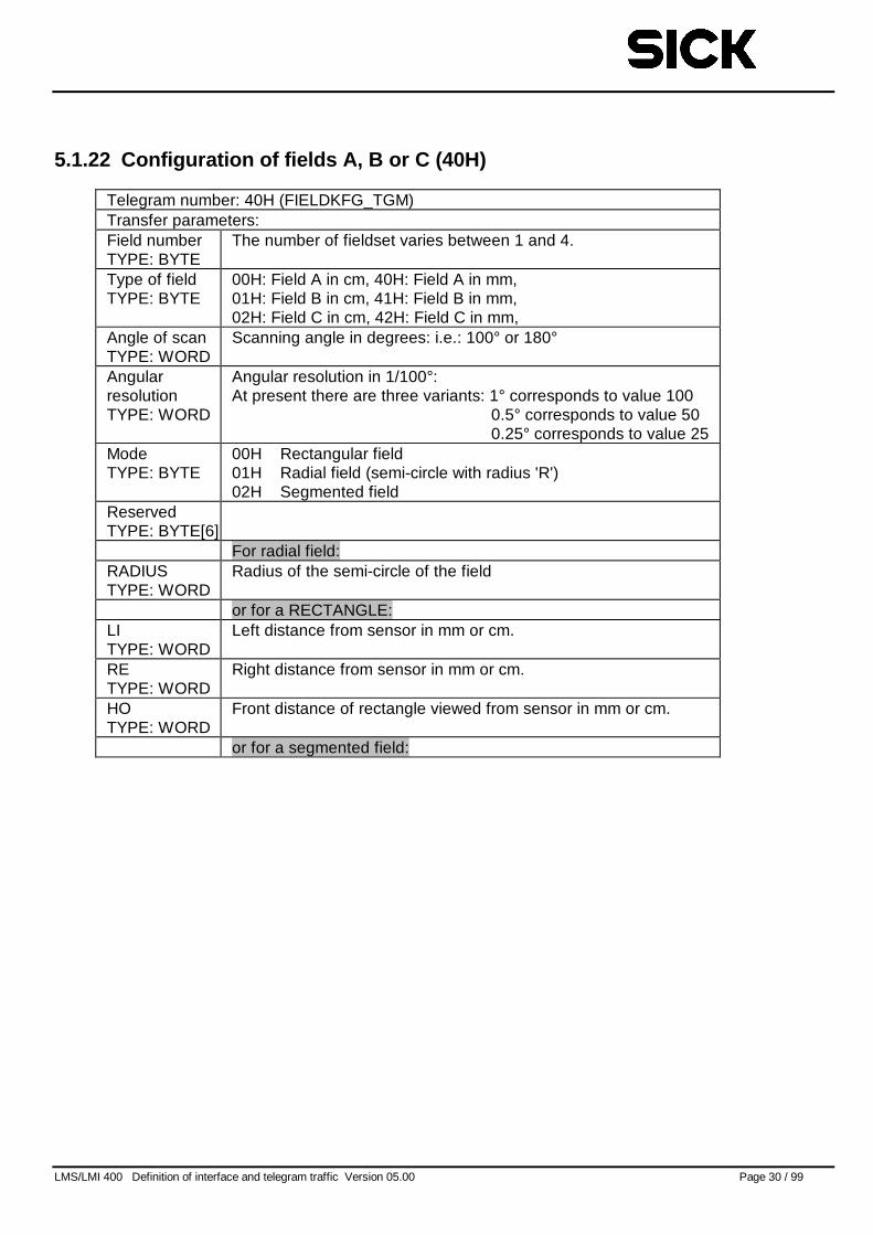
5.1.22 Configuration of fields A, B or C (40H)
Telegram number: 40H (FIELDKFG_TGM)Transfer parameters:Field numberTYPE: BYTE
The number of fieldset varies between 1 and 4.
Type of fieldTYPE: BYTE
00H: Field A in cm, 40H: Field A in mm,01H: Field B in cm, 41H: Field B in mm,02H: Field C in cm, 42H: Field C in mm,
Angle of scanTYPE: WORD
Scanning angle in degrees: i.e.: 100° or 180°
AngularresolutionTYPE: WORD
Angular resolution in 1/100°:At present there are three variants: 1° corresponds to value 100
0.5° corresponds to value 500.25° corresponds to value 25
ModeTYPE: BYTE
00H Rectangular field01H Radial field (semi-circle with radius 'R')02H Segmented field
ReservedTYPE: BYTE[6]
For radial field:RADIUSTYPE: WORD
Radius of the semi-circle of the field
or for a RECTANGLE:LITYPE: WORD
Left distance from sensor in mm or cm.
RETYPE: WORD
Right distance from sensor in mm or cm.
HOTYPE: WORD
Front distance of rectangle viewed from sensor in mm or cm.
or for a segmented field:
LMS/LMI 400 Definition of interface and telegram traffic Version 05.00 Page 31 / 99
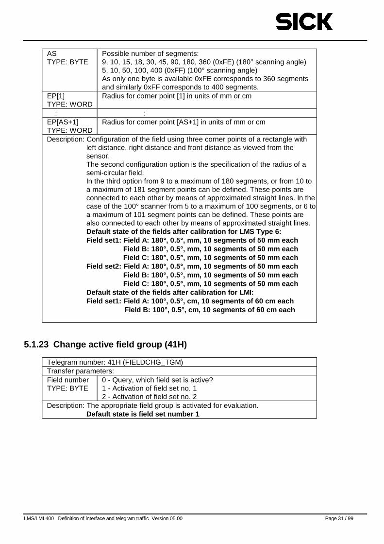
ASTYPE: BYTE
Possible number of segments:9, 10, 15, 18, 30, 45, 90, 180, 360 (0xFE) (180° scanning angle)5, 10, 50, 100, 400 (0xFF) (100° scanning angle)As only one byte is available 0xFE corresponds to 360 segmentsand similarly 0xFF corresponds to 400 segments.
EP[1]TYPE: WORD
Radius for corner point [1] in units of mm or cm
: :EP[AS+1]TYPE: WORD
Radius for corner point [AS+1] in units of mm or cm
Description: Configuration of the field using three corner points of a rectangle withleft distance, right distance and front distance as viewed from thesensor.The second configuration option is the specification of the radius of asemi-circular field.In the third option from 9 to a maximum of 180 segments, or from 10 toa maximum of 181 segment points can be defined. These points areconnected to each other by means of approximated straight lines. In thecase of the 100° scanner from 5 to a maximum of 100 segments, or 6 toa maximum of 101 segment points can be defined. These points arealso connected to each other by means of approximated straight lines.Default state of the fields after calibration for LMS Type 6:Field set1: Field A: 180°, 0.5°, mm, 10 segments of 50 mm each
Field B: 180°, 0.5°, mm, 10 segments of 50 mm eachField C: 180°, 0.5°, mm, 10 segments of 50 mm each
Field set2: Field A: 180°, 0.5°, mm, 10 segments of 50 mm eachField B: 180°, 0.5°, mm, 10 segments of 50 mm eachField C: 180°, 0.5°, mm, 10 segments of 50 mm each
Default state of the fields after calibration for LMI:Field set1: Field A: 100°, 0.5°, cm, 10 segments of 60 cm each
Field B: 100°, 0.5°, cm, 10 segments of 60 cm each
5.1.23 Change active field group (41H)
Telegram number: 41H (FIELDCHG_TGM)Transfer parameters:Field numberTYPE: BYTE
0 - Query, which field set is active?1 - Activation of field set no. 12 - Activation of field set no. 2
Description: The appropriate field group is activated for evaluation.Default state is field set number 1
LMS/LMI 400 Definition of interface and telegram traffic Version 05.00 Page 32 / 99
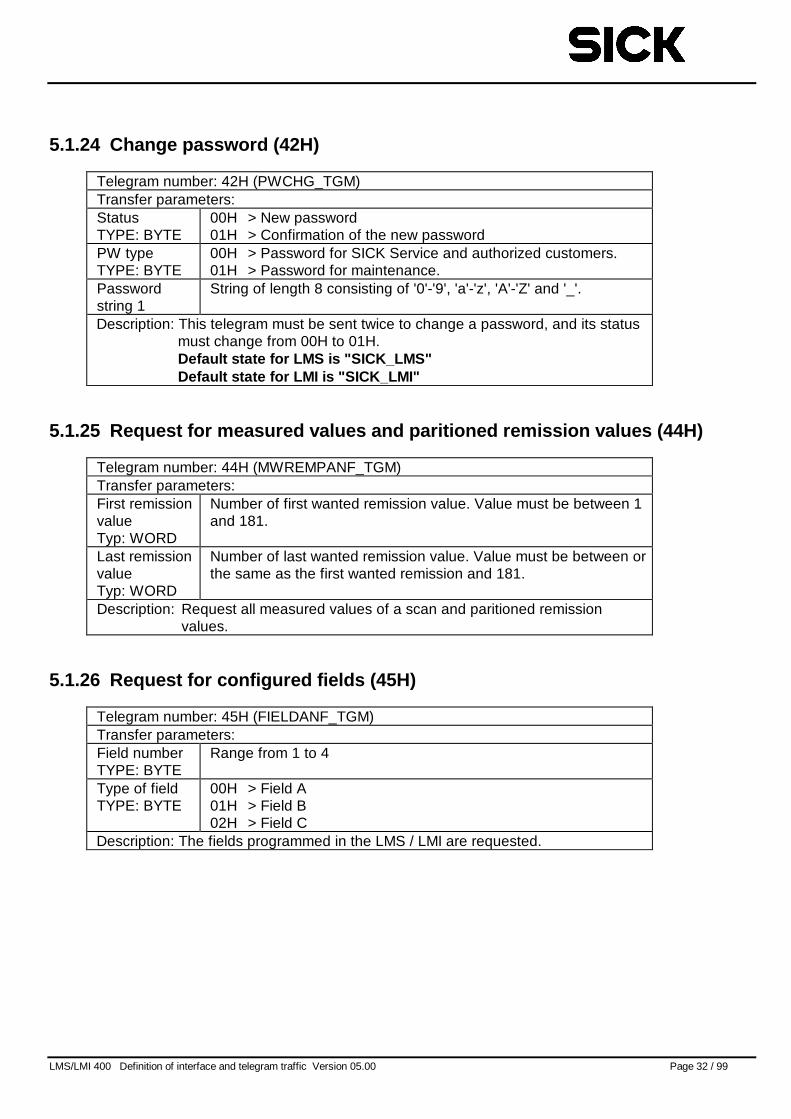
5.1.24 Change password (42H)
Telegram number: 42H (PWCHG_TGM)Transfer parameters:StatusTYPE: BYTE
00H > New password01H > Confirmation of the new password
PW typeTYPE: BYTE
00H > Password for SICK Service and authorized customers.01H > Password for maintenance.
Passwordstring 1
String of length 8 consisting of '0'-'9', 'a'-'z', 'A'-'Z' and '_'.
Description: This telegram must be sent twice to change a password, and its statusmust change from 00H to 01H.Default state for LMS is "SICK_LMS"Default state for LMI is "SICK_LMI"
5.1.25 Request for measured values and paritioned remission values (44H)
Telegram number: 44H (MWREMPANF_TGM)Transfer parameters:First remissionvalueTyp: WORD
Number of first wanted remission value. Value must be between 1and 181.
Last remissionvalueTyp: WORD
Number of last wanted remission value. Value must be between orthe same as the first wanted remission and 181.
Description: Request all measured values of a scan and paritioned remissionvalues.
5.1.26 Request for configured fields (45H)
Telegram number: 45H (FIELDANF_TGM)Transfer parameters:Field numberTYPE: BYTE
Range from 1 to 4
Type of fieldTYPE: BYTE
00H > Field A01H > Field B02H > Field C
Description: The fields programmed in the LMS / LMI are requested.
LMS/LMI 400 Definition of interface and telegram traffic Version 05.00 Page 33 / 99
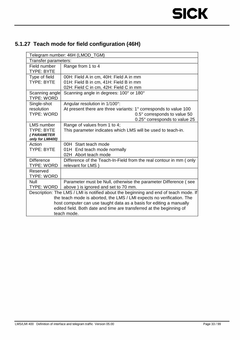
5.1.27 Teach mode for field configuration (46H)
Telegram number: 46H (LMOD_TGM)Transfer parameters:Field numberTYPE: BYTE
Range from 1 to 4
Type of fieldTYPE: BYTE
00H: Field A in cm, 40H: Field A in mm01H: Field B in cm, 41H: Field B in mm02H: Field C in cm, 42H: Field C in mm
Scanning angleTYPE: WORD
Scanning angle in degrees: 100° or 180°
Single-shotresolutionTYPE: WORD
Angular resolution in 1/100°:At present there are three variants: 1° corresponds to value 100
0.5° corresponds to value 500.25° corresponds to value 25
LMS numberTYPE: BYTE( PARAMETERonly for LMI400)
Range of values from 1 to 4;This parameter indicates which LMS will be used to teach-in.
ActionTYPE: BYTE
00H Start teach mode01H End teach mode normally02H Abort teach mode
DifferenceTYPE: WORD
Difference of the Teach-In-Field from the real contour in mm ( onlyrelevant for LMS )
ReservedTYPE: WORDNullTYPE: WORD
Parameter must be Null, otherwise the parameter Difference ( seeabove ) is ignored and set to 70 mm.
Description: The LMS / LMI is notified about the beginning and end of teach mode. Ifthe teach mode is aborted, the LMS / LMI expects no verification. Thehost computer can use taught data as a basis for editing a manuallyedited field. Both date and time are transferred at the beginning ofteach mode.
LMS/LMI 400 Definition of interface and telegram traffic Version 05.00 Page 34 / 99
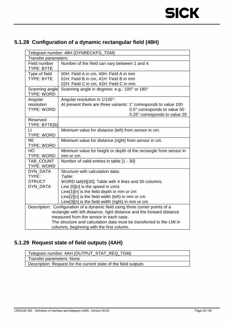
5.1.28 Configuration of a dynamic rectangular field (48H)
Telegram number: 48H (DYNRECKFG_TGM)Transfer parameters:Field numberTYPE: BYTE
Number of the field can vary between 1 and 4.
Type of fieldTYPE: BYTE
00H: Field A in cm, 40H: Field A in mm01H: Field B in cm, 41H: Field B in mm02H: Field C in cm, 42H: Field C in mm
Scanning angleTYPE: WORD
Scanning angle in degrees: e.g.: 100° or 180°
AngularresolutionTYPE: WORD
Angular resolution in 1/100°:At present there are three variants: 1° corresponds to value 100
0.5° corresponds to value 500.25° corresponds to value 25
ReservedTYPE: BYTE[6]LITYPE: WORD
Minimum value for distance (left) from sensor in cm.
RETYPE: WORD
Minimum value for distance (right) from sensor in cm.
HOTYPE: WORD
Minimum value for height or depth of the rectangle from sensor inmm or cm.
TAB_COUNTTYPE: WORD
Number of valid entries in table [1 - 30]
DYN_DATATYPE:STRUCTDYN_DATA
Structure with calculation data:Table:WORD tab[4][30]; Table with 4 lines and 30 columns.Line [0][n] is the speed in cm/sLine[1][n] is the field depth in mm or cmLine[2][n] is the field width (left) in mm or cmLine[3][n] is the field width (right) in mm or cm
Description: Configuration of a dynamic field using three corner points of arectangle with left distance, right distance and the forward distancemeasured from the sensor in each case.The structure and calculation data must be transferred to the LMI incolumns, beginning with the first column.
5.1.29 Request state of field outputs (4AH)
Telegram number: 4AH (OUTPUT_STAT_REQ_TGM)Transfer parameters: NoneDescription: Request for the current state of the field outputs
LMS/LMI 400 Definition of interface and telegram traffic Version 05.00 Page 35 / 99
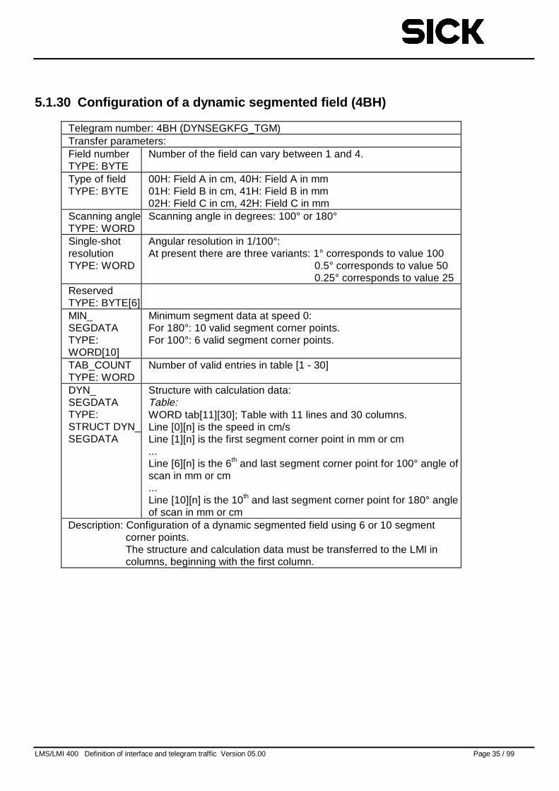
5.1.30 Configuration of a dynamic segmented field (4BH)
Telegram number: 4BH (DYNSEGKFG_TGM)Transfer parameters:Field numberTYPE: BYTE
Number of the field can vary between 1 and 4.
Type of fieldTYPE: BYTE
00H: Field A in cm, 40H: Field A in mm01H: Field B in cm, 41H: Field B in mm02H: Field C in cm, 42H: Field C in mm
Scanning angleTYPE: WORD
Scanning angle in degrees: 100° or 180°
Single-shotresolutionTYPE: WORD
Angular resolution in 1/100°:At present there are three variants: 1° corresponds to value 100
0.5° corresponds to value 500.25° corresponds to value 25
ReservedTYPE: BYTE[6]MIN_SEGDATATYPE:WORD[10]
Minimum segment data at speed 0:For 180°: 10 valid segment corner points.For 100°: 6 valid segment corner points.
TAB_COUNTTYPE: WORD
Number of valid entries in table [1 - 30]
DYN_SEGDATATYPE:STRUCT DYN_SEGDATA
Structure with calculation data:Table:WORD tab[11][30]; Table with 11 lines and 30 columns.Line [0][n] is the speed in cm/sLine [1][n] is the first segment corner point in mm or cm...Line [6][n] is the 6th and last segment corner point for 100° angle ofscan in mm or cm...Line [10][n] is the 10th and last segment corner point for 180° angleof scan in mm or cm
Description: Configuration of a dynamic segmented field using 6 or 10 segmentcorner points.The structure and calculation data must be transferred to the LMI incolumns, beginning with the first column.
LMS/LMI 400 Definition of interface and telegram traffic Version 05.00 Page 36 / 99
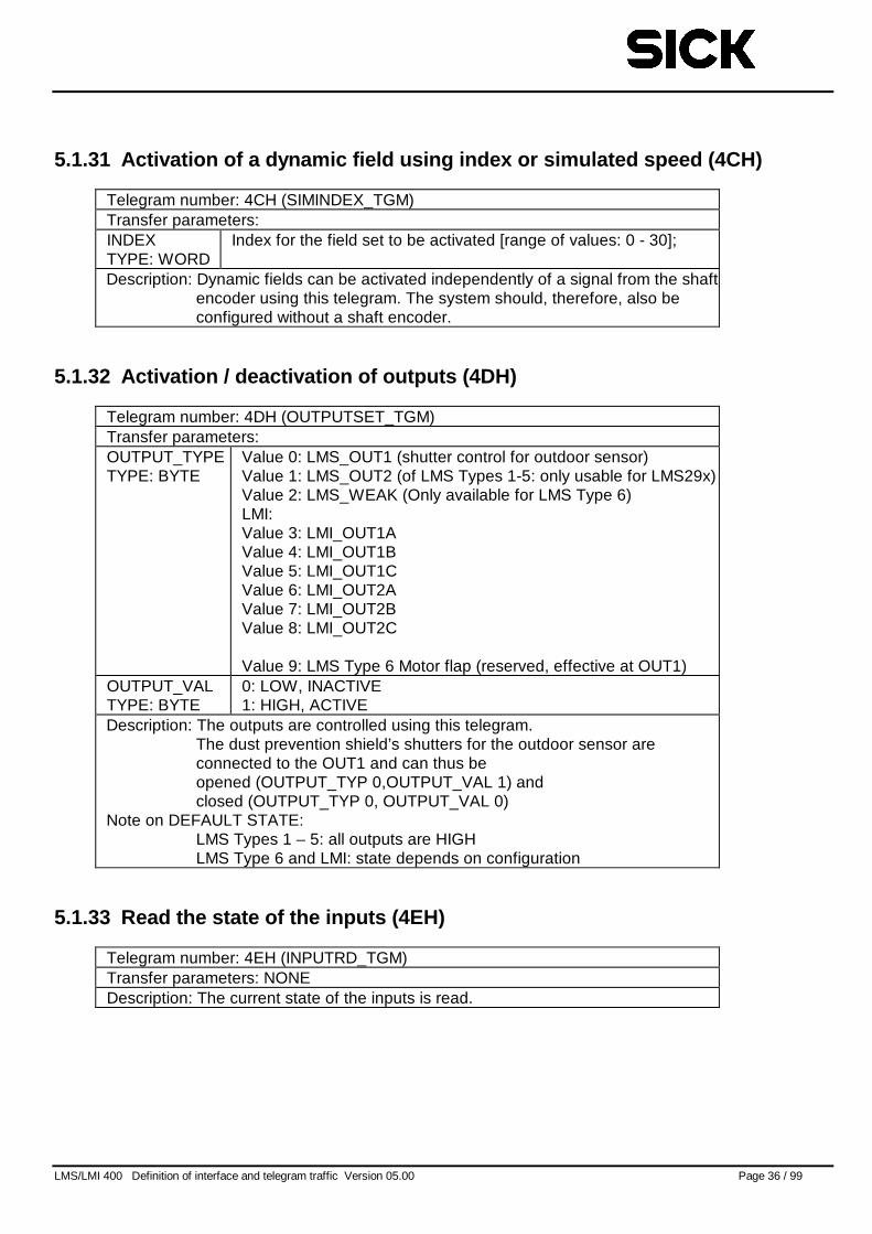
5.1.31 Activation of a dynamic field using index or simulated speed (4CH)
Telegram number: 4CH (SIMINDEX_TGM)Transfer parameters:INDEXTYPE: WORD
Index for the field set to be activated [range of values: 0 - 30];
Description: Dynamic fields can be activated independently of a signal from the shaftencoder using this telegram. The system should, therefore, also beconfigured without a shaft encoder.
5.1.32 Activation / deactivation of outputs (4DH)
Telegram number: 4DH (OUTPUTSET_TGM)Transfer parameters:OUTPUT_TYPETYPE: BYTE
Value 0: LMS_OUT1 (shutter control for outdoor sensor)Value 1: LMS_OUT2 (of LMS Types 1-5: only usable for LMS29x)Value 2: LMS_WEAK (Only available for LMS Type 6)LMI:Value 3: LMI_OUT1AValue 4: LMI_OUT1BValue 5: LMI_OUT1CValue 6: LMI_OUT2AValue 7: LMI_OUT2BValue 8: LMI_OUT2C
Value 9: LMS Type 6 Motor flap (reserved, effective at OUT1)OUTPUT_VALTYPE: BYTE
0: LOW, INACTIVE1: HIGH, ACTIVE
Description: The outputs are controlled using this telegram.The dust prevention shield’s shutters for the outdoor sensor areconnected to the OUT1 and can thus beopened (OUTPUT_TYP 0,OUTPUT_VAL 1) andclosed (OUTPUT_TYP 0, OUTPUT_VAL 0)
Note on DEFAULT STATE:LMS Types 1 – 5: all outputs are HIGHLMS Type 6 and LMI: state depends on configuration
5.1.33 Read the state of the inputs (4EH)
Telegram number: 4EH (INPUTRD_TGM)Transfer parameters: NONEDescription: The current state of the inputs is read.
LMS/LMI 400 Definition of interface and telegram traffic Version 05.00 Page 37 / 99
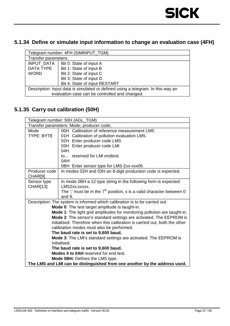
5.1.34 Define or simulate input information to change an evaluation case (4FH)
Telegram number: 4FH (SIMINPUT_TGM)Transfer parameters:INPUT_DATADATA TYPEWORD
Bit 0: State of input ABit 1: State of input BBit 2: State of input CBit 3: State of input DBit 4: State of input RESTART
Description: Input data is simulated or defined using a telegram. In this way anevaluation case can be controlled and changed.
5.1.35 Carry out calibration (50H)
Telegram number: 50H (AGL_TGM)Transfer parameters: Mode; producer code;ModeTYPE: BYTE
00H Calibration of reference measurement LMS01H Calibration of pollution evaluation LMS02H Enter producer code LMS03H Enter producer code LMI04Hto... reserved for LMI endtest.0AH0BH Enter sensor type for LMS-2xx-xxx06
Producer codeCHAR[9]
In modes 02H and 03H an 8-digit production code is expected.
Sensor typeCHAR[13]
In mode 0BH a 12 type string in the following form is expected:LMS2xx;xxxxx.The ';' must be in the 7th position, x is a valid character between 0and 9.
Description: The system is informed which calibration is to be carried out.Mode 0 : The test target amplitude is taught-in.Mode 1 : The light grid amplitudes for monitoring pollution are taught-in.Mode 2 : The sensor's standard settings are activated. The EEPROM isinitialised. Therefore when this calibration is carried out, both the othercalibration modes must also be performed.The baud rate is set to 9,600 baud.Mode 3 : The LMI's standard settings are activated. The EEPROM isinitialised.The baud rate is set to 9,600 baud.Modes 4 to 0AH reserved for end test.Mode 0BH: Defines the LMS type.
The LMS and LMI can be distinguished from one another by the address used.
LMS/LMI 400 Definition of interface and telegram traffic Version 05.00 Page 38 / 99
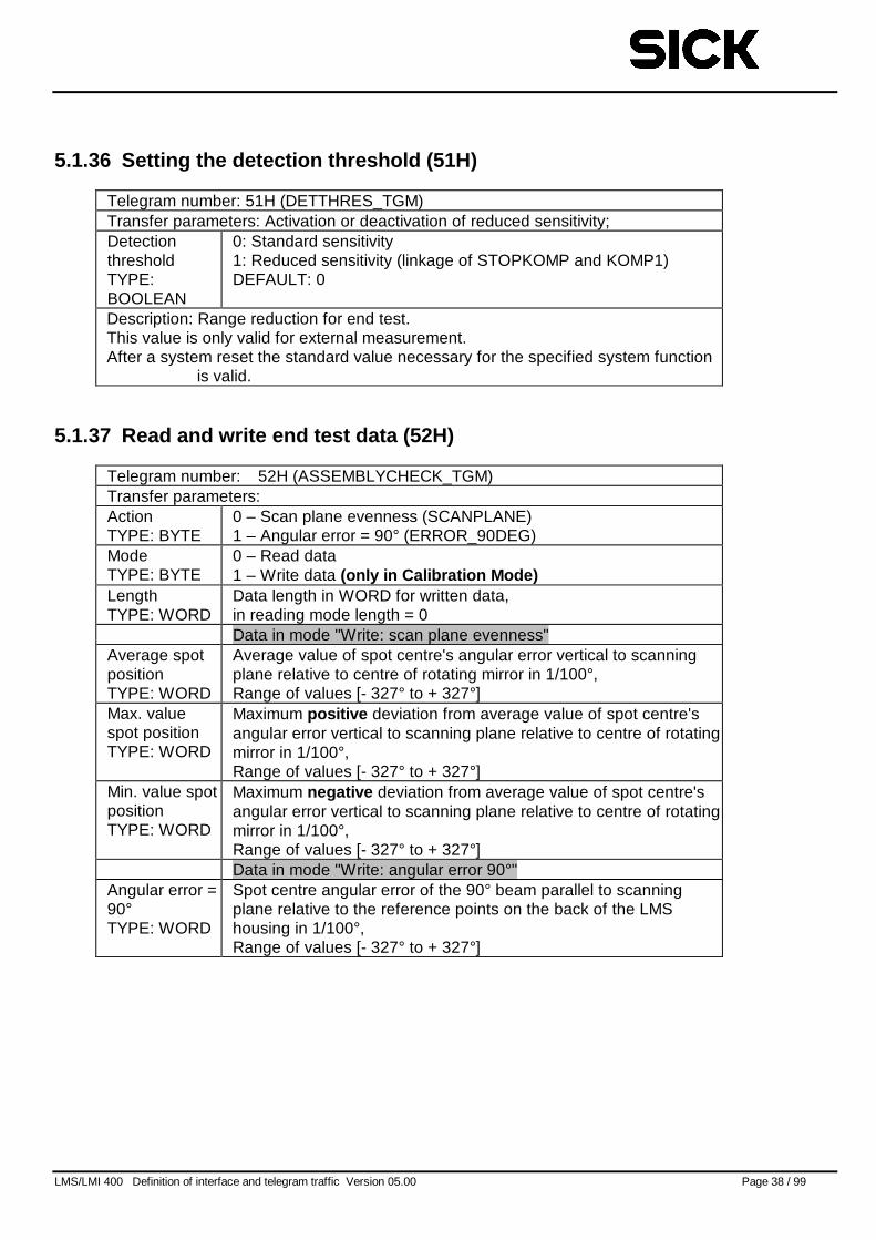
5.1.36 Setting the detection threshold (51H)
Telegram number: 51H (DETTHRES_TGM)Transfer parameters: Activation or deactivation of reduced sensitivity;DetectionthresholdTYPE:BOOLEAN
0: Standard sensitivity1: Reduced sensitivity (linkage of STOPKOMP and KOMP1)DEFAULT: 0
Description: Range reduction for end test.This value is only valid for external measurement.After a system reset the standard value necessary for the specified system function
is valid.
5.1.37 Read and write end test data (52H)
Telegram number: 52H (ASSEMBLYCHECK_TGM)Transfer parameters:ActionTYPE: BYTE
0 – Scan plane evenness (SCANPLANE)1 – Angular error = 90° (ERROR_90DEG)
ModeTYPE: BYTE
0 – Read data1 – Write data (only in Calibration Mode)
LengthTYPE: WORD
Data length in WORD for written data,in reading mode length = 0Data in mode "Write: scan plane evenness"
Average spotpositionTYPE: WORD
Average value of spot centre's angular error vertical to scanningplane relative to centre of rotating mirror in 1/100°,Range of values [- 327° to + 327°]
Max. valuespot positionTYPE: WORD
Maximum positive deviation from average value of spot centre'sangular error vertical to scanning plane relative to centre of rotatingmirror in 1/100°,Range of values [- 327° to + 327°]
Min. value spotpositionTYPE: WORD
Maximum negative deviation from average value of spot centre'sangular error vertical to scanning plane relative to centre of rotatingmirror in 1/100°,Range of values [- 327° to + 327°]Data in mode "Write: angular error 90°"
Angular error =90°TYPE: WORD
Spot centre angular error of the 90° beam parallel to scanningplane relative to the reference points on the back of the LMShousing in 1/100°,Range of values [- 327° to + 327°]
LMS/LMI 400 Definition of interface and telegram traffic Version 05.00 Page 39 / 99
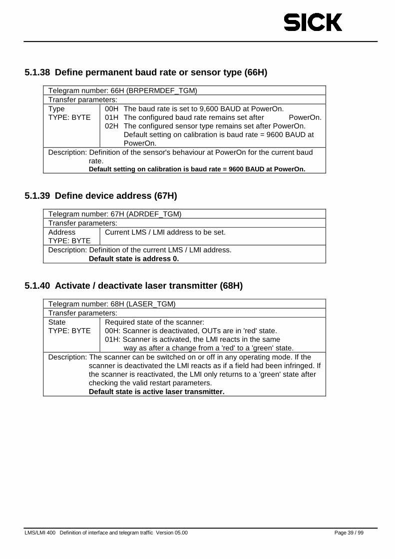
5.1.38 Define permanent baud rate or sensor type (66H)
Telegram number: 66H (BRPERMDEF_TGM)Transfer parameters:TypeTYPE: BYTE
00H The baud rate is set to 9,600 BAUD at PowerOn.01H The configured baud rate remains set after PowerOn.02H The configured sensor type remains set after PowerOn.
Default setting on calibration is baud rate = 9600 BAUD atPowerOn.
Description: Definition of the sensor's behaviour at PowerOn for the current baudrate.Default setting on calibration is baud rate = 9600 BAUD at PowerOn.
5.1.39 Define device address (67H)
Telegram number: 67H (ADRDEF_TGM)Transfer parameters:AddressTYPE: BYTE
Current LMS / LMI address to be set.
Description: Definition of the current LMS / LMI address.Default state is address 0.
5.1.40 Activate / deactivate laser transmitter (68H)
Telegram number: 68H (LASER_TGM)Transfer parameters:StateTYPE: BYTE
Required state of the scanner:00H: Scanner is deactivated, OUTs are in 'red' state.01H: Scanner is activated, the LMI reacts in the same
way as after a change from a 'red' to a 'green' state.Description: The scanner can be switched on or off in any operating mode. If the
scanner is deactivated the LMI reacts as if a field had been infringed. Ifthe scanner is reactivated, the LMI only returns to a 'green' state afterchecking the valid restart parameters.Default state is active laser transmitter.
LMS/LMI 400 Definition of interface and telegram traffic Version 05.00 Page 40 / 99
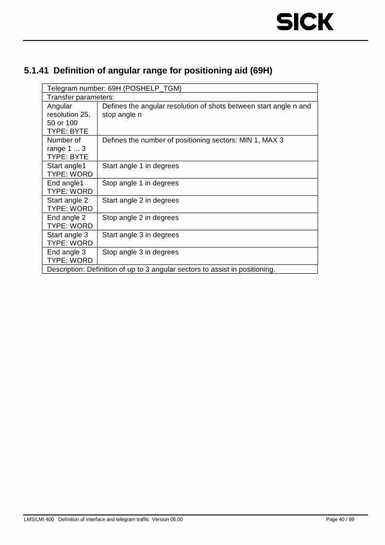
5.1.41 Definition of angular range for positioning aid (69H)
Telegram number: 69H (POSHELP_TGM)Transfer parameters:Angularresolution 25,50 or 100TYPE: BYTE
Defines the angular resolution of shots between start angle n andstop angle n
Number ofrange 1 ... 3TYPE: BYTE
Defines the number of positioning sectors: MIN 1, MAX 3
Start angle1TYPE: WORD
Start angle 1 in degrees
End angle1TYPE: WORD
Stop angle 1 in degrees
Start angle 2TYPE: WORD
Start angle 2 in degrees
End angle 2TYPE: WORD
Stop angle 2 in degrees
Start angle 3TYPE: WORD
Start angle 3 in degrees
End angle 3TYPE: WORD
Stop angle 3 in degrees
Description: Definition of up to 3 angular sectors to assist in positioning.
LMS/LMI 400 Definition of interface and telegram traffic Version 05.00 Page 41 / 99
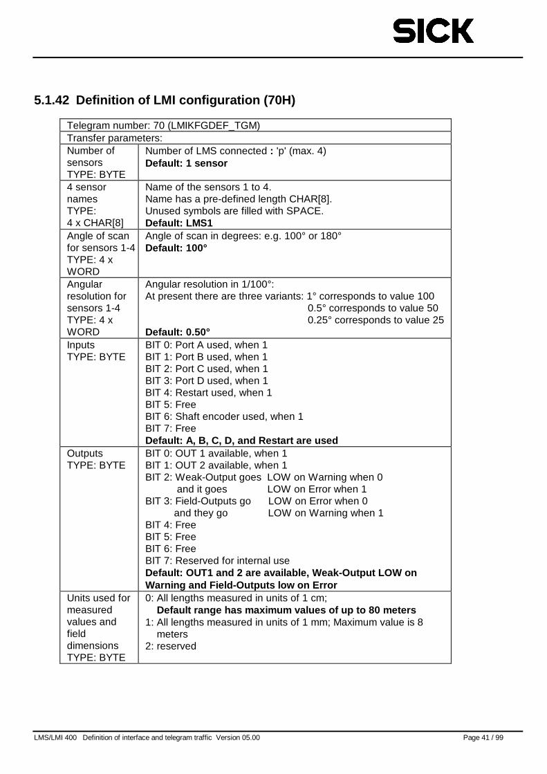
5.1.42 Definition of LMI configuration (70H)
Telegram number: 70 (LMIKFGDEF_TGM)Transfer parameters:Number ofsensorsTYPE: BYTE
Number of LMS connected : 'p' (max. 4)Default: 1 sensor
4 sensornamesTYPE:4 x CHAR[8]
Name of the sensors 1 to 4.Name has a pre-defined length CHAR[8].Unused symbols are filled with SPACE.Default: LMS1
Angle of scanfor sensors 1-4TYPE: 4 xWORD
Angle of scan in degrees: e.g. 100° or 180°Default: 100°
Angularresolution forsensors 1-4TYPE: 4 xWORD
Angular resolution in 1/100°:At present there are three variants: 1° corresponds to value 100
0.5° corresponds to value 500.25° corresponds to value 25
Default: 0.50°InputsTYPE: BYTE
BIT 0: Port A used, when 1BIT 1: Port B used, when 1BIT 2: Port C used, when 1BIT 3: Port D used, when 1BIT 4: Restart used, when 1BIT 5: FreeBIT 6: Shaft encoder used, when 1BIT 7: FreeDefault: A, B, C, D, and Restart are used
OutputsTYPE: BYTE
BIT 0: OUT 1 available, when 1BIT 1: OUT 2 available, when 1BIT 2: Weak-Output goes LOW on Warning when 0
and it goes LOW on Error when 1BIT 3: Field-Outputs go LOW on Error when 0
and they go LOW on Warning when 1BIT 4: FreeBIT 5: FreeBIT 6: FreeBIT 7: Reserved for internal useDefault: OUT1 and 2 are available, Weak-Output LOW onWarning and Field-Outputs low on Error
Units used formeasuredvalues andfielddimensionsTYPE: BYTE
0: All lengths measured in units of 1 cm;Default range has maximum values of up to 80 meters
1: All lengths measured in units of 1 mm; Maximum value is 8meters
2: reserved
LMS/LMI 400 Definition of interface and telegram traffic Version 05.00 Page 42 / 99
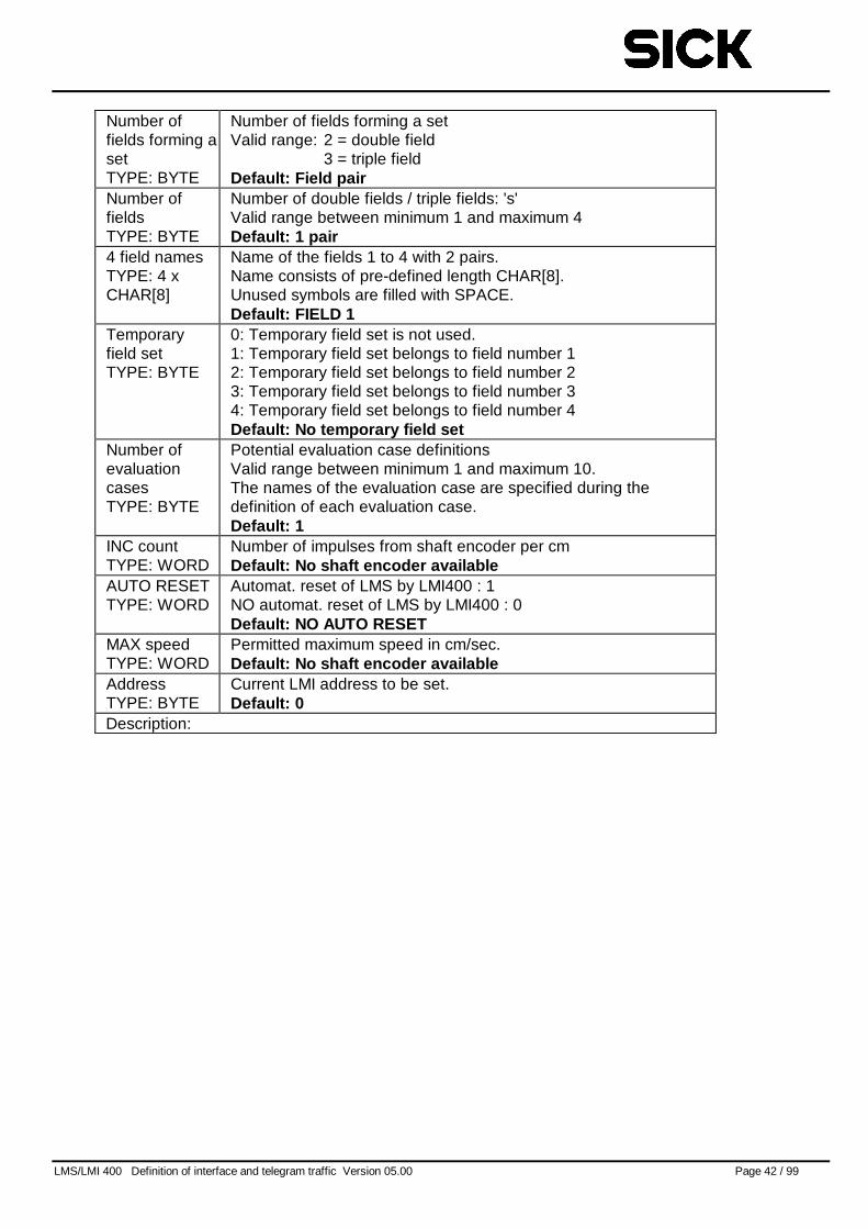
Number offields forming asetTYPE: BYTE
Number of fields forming a setValid range: 2 = double field
3 = triple fieldDefault: Field pair
Number offieldsTYPE: BYTE
Number of double fields / triple fields: 's'Valid range between minimum 1 and maximum 4Default: 1 pair
4 field namesTYPE: 4 xCHAR[8]
Name of the fields 1 to 4 with 2 pairs.Name consists of pre-defined length CHAR[8].Unused symbols are filled with SPACE.Default: FIELD 1
Temporaryfield setTYPE: BYTE
0: Temporary field set is not used.1: Temporary field set belongs to field number 12: Temporary field set belongs to field number 23: Temporary field set belongs to field number 34: Temporary field set belongs to field number 4Default: No temporary field set
Number ofevaluationcasesTYPE: BYTE
Potential evaluation case definitionsValid range between minimum 1 and maximum 10.The names of the evaluation case are specified during thedefinition of each evaluation case.Default: 1
INC countTYPE: WORD
Number of impulses from shaft encoder per cmDefault: No shaft encoder available
AUTO RESETTYPE: WORD
Automat. reset of LMS by LMI400 : 1NO automat. reset of LMS by LMI400 : 0Default: NO AUTO RESET
MAX speedTYPE: WORD
Permitted maximum speed in cm/sec.Default: No shaft encoder available
AddressTYPE: BYTE
Current LMI address to be set.Default: 0
Description:
LMS/LMI 400 Definition of interface and telegram traffic Version 05.00 Page 43 / 99
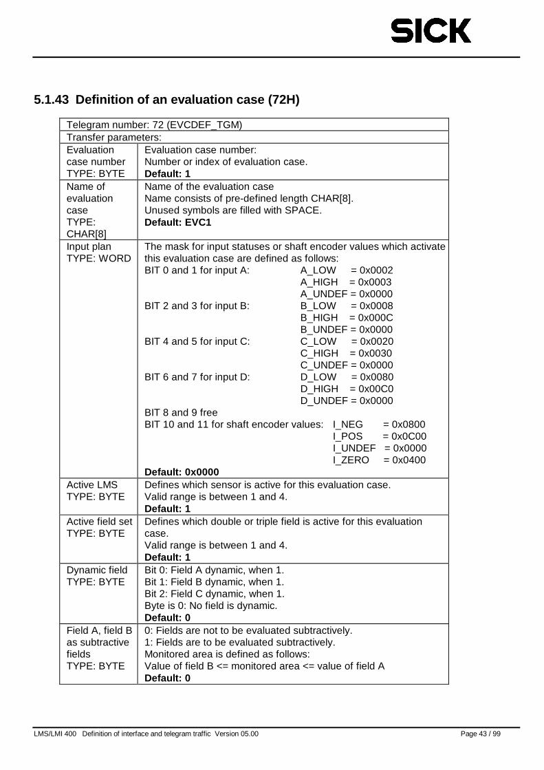
5.1.43 Definition of an evaluation case (72H)
Telegram number: 72 (EVCDEF_TGM)Transfer parameters:Evaluationcase numberTYPE: BYTE
Evaluation case number:Number or index of evaluation case.Default: 1
Name ofevaluationcaseTYPE:CHAR[8]
Name of the evaluation caseName consists of pre-defined length CHAR[8].Unused symbols are filled with SPACE.Default: EVC1
Input planTYPE: WORD
The mask for input statuses or shaft encoder values which activatethis evaluation case are defined as follows:BIT 0 and 1 for input A: A_LOW = 0x0002
A_HIGH = 0x0003A_UNDEF = 0x0000
BIT 2 and 3 for input B: B_LOW = 0x0008B_HIGH = 0x000CB_UNDEF = 0x0000
BIT 4 and 5 for input C: C_LOW = 0x0020C_HIGH = 0x0030C_UNDEF = 0x0000
BIT 6 and 7 for input D: D_LOW = 0x0080D_HIGH = 0x00C0D_UNDEF = 0x0000
BIT 8 and 9 freeBIT 10 and 11 for shaft encoder values: I_NEG = 0x0800
I_POS = 0x0C00I_UNDEF = 0x0000I_ZERO = 0x0400
Default: 0x0000Active LMSTYPE: BYTE
Defines which sensor is active for this evaluation case.Valid range is between 1 and 4.Default: 1
Active field setTYPE: BYTE
Defines which double or triple field is active for this evaluationcase.Valid range is between 1 and 4.Default: 1
Dynamic fieldTYPE: BYTE
Bit 0: Field A dynamic, when 1.Bit 1: Field B dynamic, when 1.Bit 2: Field C dynamic, when 1.Byte is 0: No field is dynamic.Default: 0
Field A, field Bas subtractivefieldsTYPE: BYTE
0: Fields are not to be evaluated subtractively.1: Fields are to be evaluated subtractively.Monitored area is defined as follows:Value of field B <= monitored area <= value of field ADefault: 0
LMS/LMI 400 Definition of interface and telegram traffic Version 05.00 Page 44 / 99
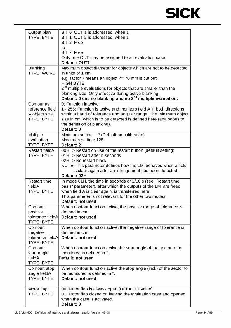
Output planTYPE: BYTE
BIT 0: OUT 1 is addressed, when 1BIT 1: OUT 2 is addressed, when 1BIT 2: FreetoBIT 7: FreeOnly one OUT may be assigned to an evaluation case.Default: OUT1
BlankingTYPE: WORD
Maximum object diameter for objects which are not to be detectedin units of 1 cm.e.g. factor 7 means an object <= 70 mm is cut out.HIGH BYTE:2nd multiple evaluations for objects that are smaller than theblanking size. Only effective during active blanking.Default: 0 cm, no blanking and no 2 nd multiple evaulation.
Contour asreference fieldA object sizeTYPE: BYTE
0: Function inactive1 - 255: Function is active and monitors field A in both directionswithin a band of tolerance and angular range. The minimum objectsize in cm, which is to be detected is defined here (analogous tothe definition of blanking).Default: 0
MultipleevaluationTYPE: BYTE
Minimum setting: 2 (Default on calibration)Maximum setting: 125.Default: 2
Restart fieldATYPE: BYTE
00H > Restart on use of the restart button (default setting)01H > Restart after n seconds02H > No restart blockNOTE: This parameter defines how the LMI behaves when a field
is clear again after an infringement has been detected.Default: 02H
Restart timefieldATYPE: BYTE
In mode 01H, the time in seconds or 1/10 s (see "Restart timebasis" parameter), after which the outputs of the LMI are freedwhen field A is clear again, is transferred here.This parameter is not relevant for the other two modes.Default: not used
Contour:positivetolerance fieldATYPE: BYTE
When contour function active, the positive range of tolerance isdefined in cm.Default: not used
Contour:negativetolerance fieldATYPE: BYTE
When contour function active, the negative range of tolerance isdefined in cm.Default: not used
Contour:start anglefieldATYPE: BYTE
When contour function active the start angle of the sector to bemonitored is defined in °.
Default: not used
Contour: stopangle fieldATYPE: BYTE
When contour function active the stop angle (incl.) of the sector tobe monitored is defined in °.Default: not used
Motor flapTYPE: BYTE
00: Motor flap is always open (DEFAULT value)01: Motor flap closed on leaving the evaluation case and openedwhen the case is activated.Default: 0
LMS/LMI 400 Definition of interface and telegram traffic Version 05.00 Page 45 / 99
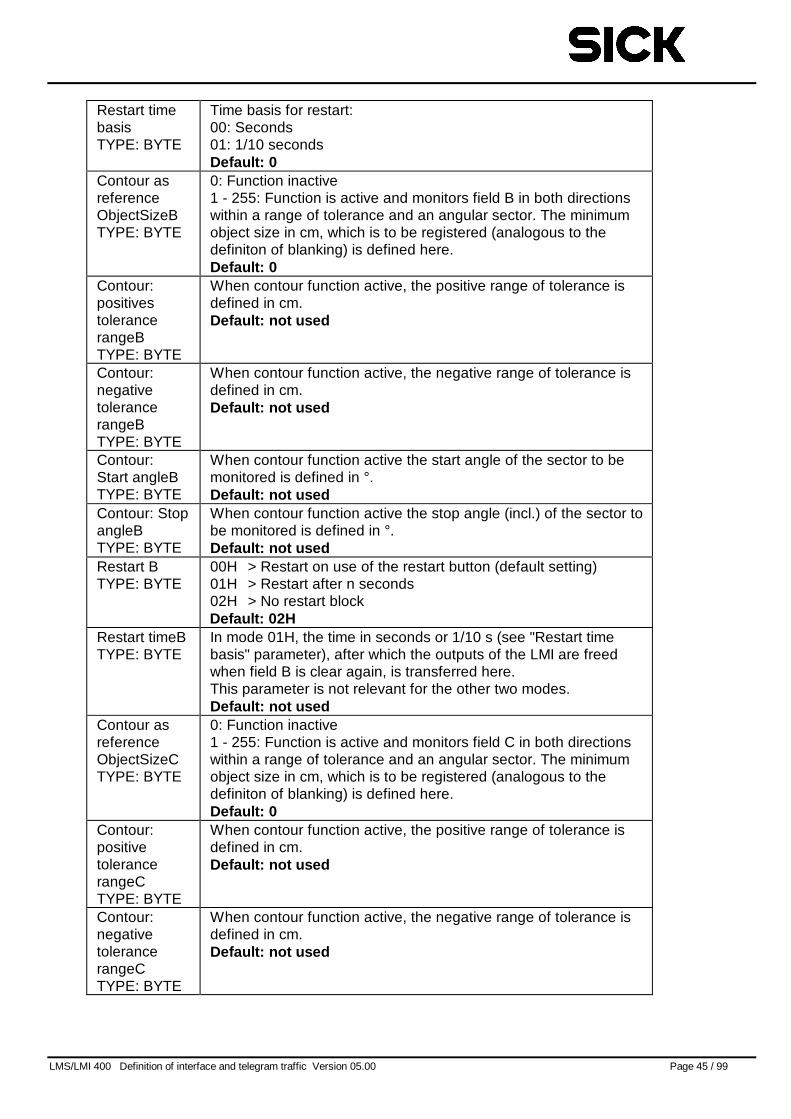
Restart timebasisTYPE: BYTE
Time basis for restart:00: Seconds01: 1/10 secondsDefault: 0
Contour asreferenceObjectSizeBTYPE: BYTE
0: Function inactive1 - 255: Function is active and monitors field B in both directionswithin a range of tolerance and an angular sector. The minimumobject size in cm, which is to be registered (analogous to thedefiniton of blanking) is defined here.Default: 0
Contour:positivestolerancerangeBTYPE: BYTE
When contour function active, the positive range of tolerance isdefined in cm.Default: not used
Contour:negativetolerancerangeBTYPE: BYTE
When contour function active, the negative range of tolerance isdefined in cm.Default: not used
Contour:Start angleBTYPE: BYTE
When contour function active the start angle of the sector to bemonitored is defined in °.Default: not used
Contour: StopangleBTYPE: BYTE
When contour function active the stop angle (incl.) of the sector tobe monitored is defined in °.Default: not used
Restart BTYPE: BYTE
00H > Restart on use of the restart button (default setting)01H > Restart after n seconds02H > No restart blockDefault: 02H
Restart timeBTYPE: BYTE
In mode 01H, the time in seconds or 1/10 s (see "Restart timebasis" parameter), after which the outputs of the LMI are freedwhen field B is clear again, is transferred here.This parameter is not relevant for the other two modes.Default: not used
Contour asreferenceObjectSizeCTYPE: BYTE
0: Function inactive1 - 255: Function is active and monitors field C in both directionswithin a range of tolerance and an angular sector. The minimumobject size in cm, which is to be registered (analogous to thedefiniton of blanking) is defined here.Default: 0
Contour:positivetolerancerangeCTYPE: BYTE
When contour function active, the positive range of tolerance isdefined in cm.Default: not used
Contour:negativetolerancerangeCTYPE: BYTE
When contour function active, the negative range of tolerance isdefined in cm.Default: not used
LMS/LMI 400 Definition of interface and telegram traffic Version 05.00 Page 46 / 99
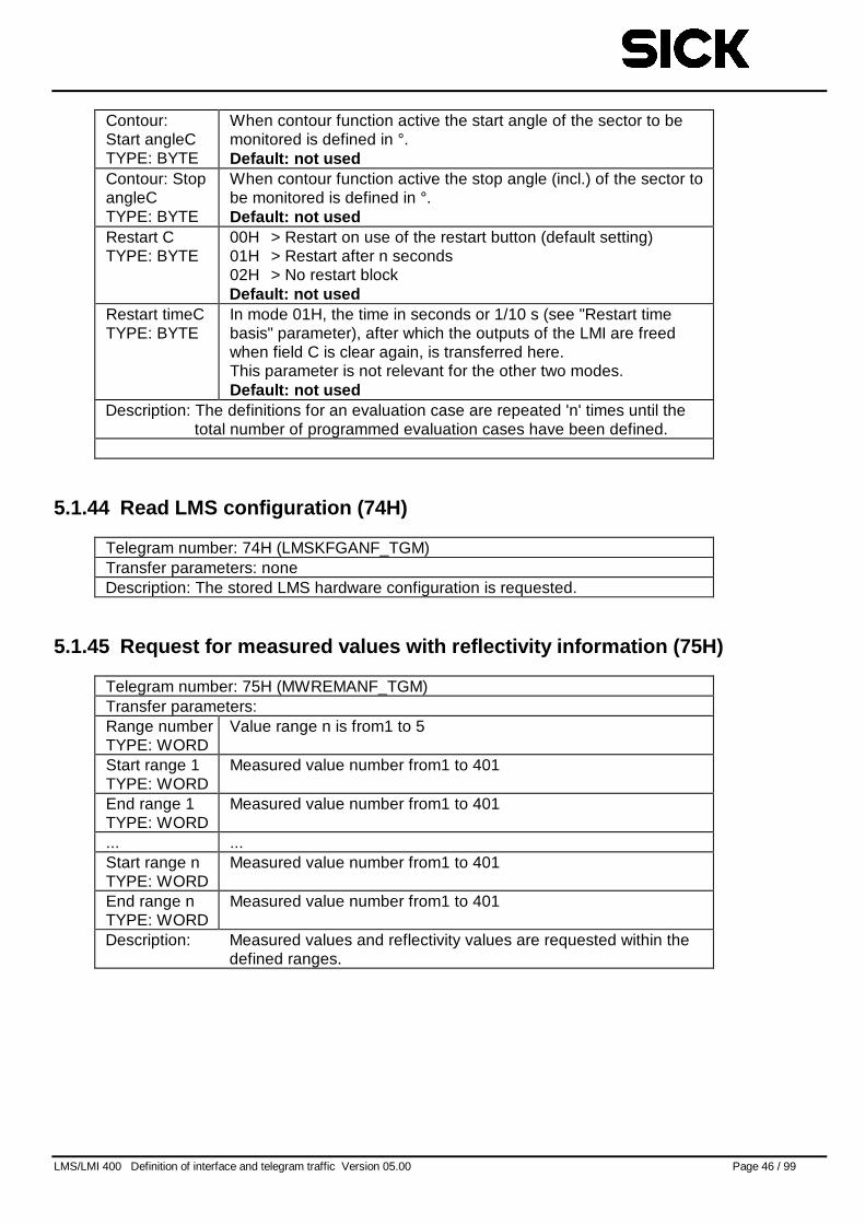
Contour:Start angleCTYPE: BYTE
When contour function active the start angle of the sector to bemonitored is defined in °.Default: not used
Contour: StopangleCTYPE: BYTE
When contour function active the stop angle (incl.) of the sector tobe monitored is defined in °.Default: not used
Restart CTYPE: BYTE
00H > Restart on use of the restart button (default setting)01H > Restart after n seconds02H > No restart blockDefault: not used
Restart timeCTYPE: BYTE
In mode 01H, the time in seconds or 1/10 s (see "Restart timebasis" parameter), after which the outputs of the LMI are freedwhen field C is clear again, is transferred here.This parameter is not relevant for the other two modes.Default: not used
Description: The definitions for an evaluation case are repeated 'n' times until thetotal number of programmed evaluation cases have been defined.
5.1.44 Read LMS configuration (74H)
Telegram number: 74H (LMSKFGANF_TGM)Transfer parameters: noneDescription: The stored LMS hardware configuration is requested.
5.1.45 Request for measured values with reflectivity information (75H)
Telegram number: 75H (MWREMANF_TGM)Transfer parameters:Range numberTYPE: WORD
Value range n is from1 to 5
Start range 1TYPE: WORD
Measured value number from1 to 401
End range 1TYPE: WORD
Measured value number from1 to 401
... ...Start range nTYPE: WORD
Measured value number from1 to 401
End range nTYPE: WORD
Measured value number from1 to 401
Description: Measured values and reflectivity values are requested within thedefined ranges.
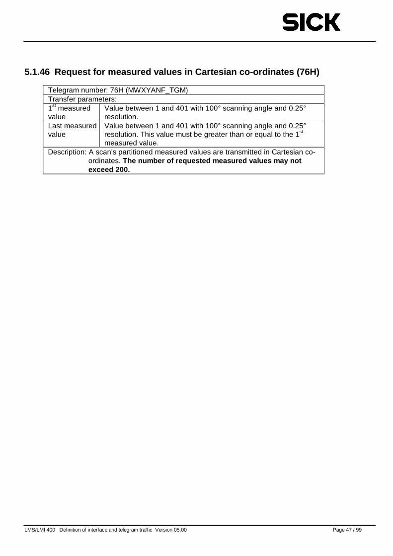
LMS/LMI 400 Definition of interface and telegram traffic Version 05.00 Page 47 / 99
5.1.46 Request for measured values in Cartesian co-ordinates (76H)
Telegram number: 76H (MWXYANF_TGM)Transfer parameters:1st measuredvalue
Value between 1 and 401 with 100° scanning angle and 0.25°resolution.
Last measuredvalue
Value between 1 and 401 with 100° scanning angle and 0.25°resolution. This value must be greater than or equal to the 1st
measured value.Description: A scan's partitioned measured values are transmitted in Cartesian co-
ordinates. The number of requested measured values may notexceed 200.
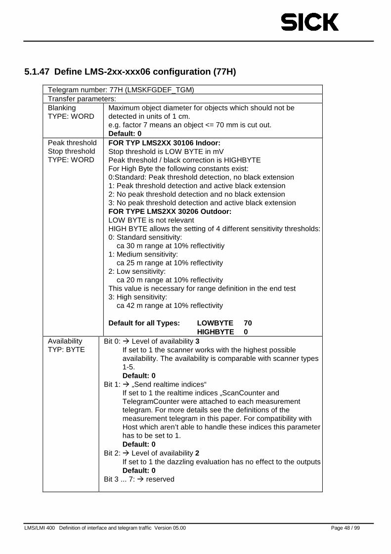
LMS/LMI 400 Definition of interface and telegram traffic Version 05.00 Page 48 / 99
5.1.47 Define LMS-2xx-xxx06 configuration (77H)
Telegram number: 77H (LMSKFGDEF_TGM)Transfer parameters:BlankingTYPE: WORD
Maximum object diameter for objects which should not bedetected in units of 1 cm.e.g. factor 7 means an object <= 70 mm is cut out.Default: 0
Peak thresholdStop thresholdTYPE: WORD
FOR TYP LMS2XX 30106 Indoor:Stop threshold is LOW BYTE in mVPeak threshold / black correction is HIGHBYTEFor High Byte the following constants exist:0:Standard: Peak threshold detection, no black extension1: Peak threshold detection and active black extension2: No peak threshold detection and no black extension3: No peak threshold detection and active black extensionFOR TYPE LMS2XX 30206 Out door:LOW BYTE is not relevantHIGH BYTE allows the setting of 4 different sensitivity thresholds:0: Standard sensitivity:
ca 30 m range at 10% reflectivitiy1: Medium sensitivity:
ca 25 m range at 10% reflectivity2: Low sensitivity:
ca 20 m range at 10% reflectivityThis value is necessary for range definition in the end test3: High sensitivity:
ca 42 m range at 10% reflectivity
Default for all Types: LOWBYTE 70HIGHBYTE 0
AvailabilityTYP: BYTE
Bit 0: � Level of availability 3If set to 1 the scanner works with the highest possibleavailability. The availability is comparable with scanner types1-5.Default: 0
Bit 1: � „Send realtime indices“If set to 1 the realtime indices „ScanCounter andTelegramCounter were attached to each measurementtelegram. For more details see the definitions of themeasurement telegram in this paper. For compatibility withHost which aren’t able to handle these indices this parameterhas to be set to 1.Default: 0
Bit 2: � Level of availability 2If set to 1 the dazzling evaluation has no effect to the outputsDefault: 0
Bit 3 ... 7: � reserved
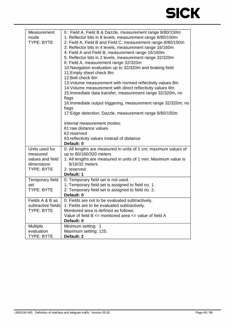
LMS/LMI 400 Definition of interface and telegram traffic Version 05.00 Page 49 / 99
MeasurementmodeTYPE: BYTE
0 : Field A, Field B & Dazzle, measurement range 8/80/150m1: Reflector bits in 8 levels, measurement range 8/80/150m2: Field A, Field B and Field C, measurement range 8/80/150m3: Reflector bits in 4 levels, measurement range 16/160m4: Field A and Field B, measurement range 16/160m5: Reflector bits in 2 levels, measurement range 32/320m6: Field A, measurement range 32/320m10:Navigation evaluation up to 32/320m and braking field11:Empty sheel check 8m12:Belt check 8m13:Volume measurement with normed reflectivity values 8m14:Volume measurement with direct reflectivity values 8m15:Immediate data transfer, measurement range 32/320m, noflags16:Immediate output triggering, measurement range 32/320m; noflags17:Edge detection, Dazzle, measurement range 8/80/150m
internal measurement modes:61:raw distance values62:reserved63:reflectivity values instead of distanceDefault: 0
Units used formeasuredvalues and fielddimensionsTYPE: BYTE
0: All lengths are measured in units of 1 cm; maximum values ofup to 80/160/320 meters1: All lengths are measured in units of 1 mm; Maximum value is
8/16/32 meters2: reservedDefault: 1
Temporary fieldsetTYPE: BYTE
0: Temporary field set is not used.1: Temporary field set is assigned to field no. 1.2: Temporary field set is assigned to field no. 2.Default: 0
Fields A & B assubtractive fieldsTYPE: BYTE
0: Fields are not to be evaluated subtractively.1: Fields are to be evaluated subtractively.Monitored area is defined as follows:Value of field B <= monitored area <= value of field ADefault: 0
MultipleevaluationTYPE: BYTE
Minimum setting: 1Maximum setting: 125.Default: 2
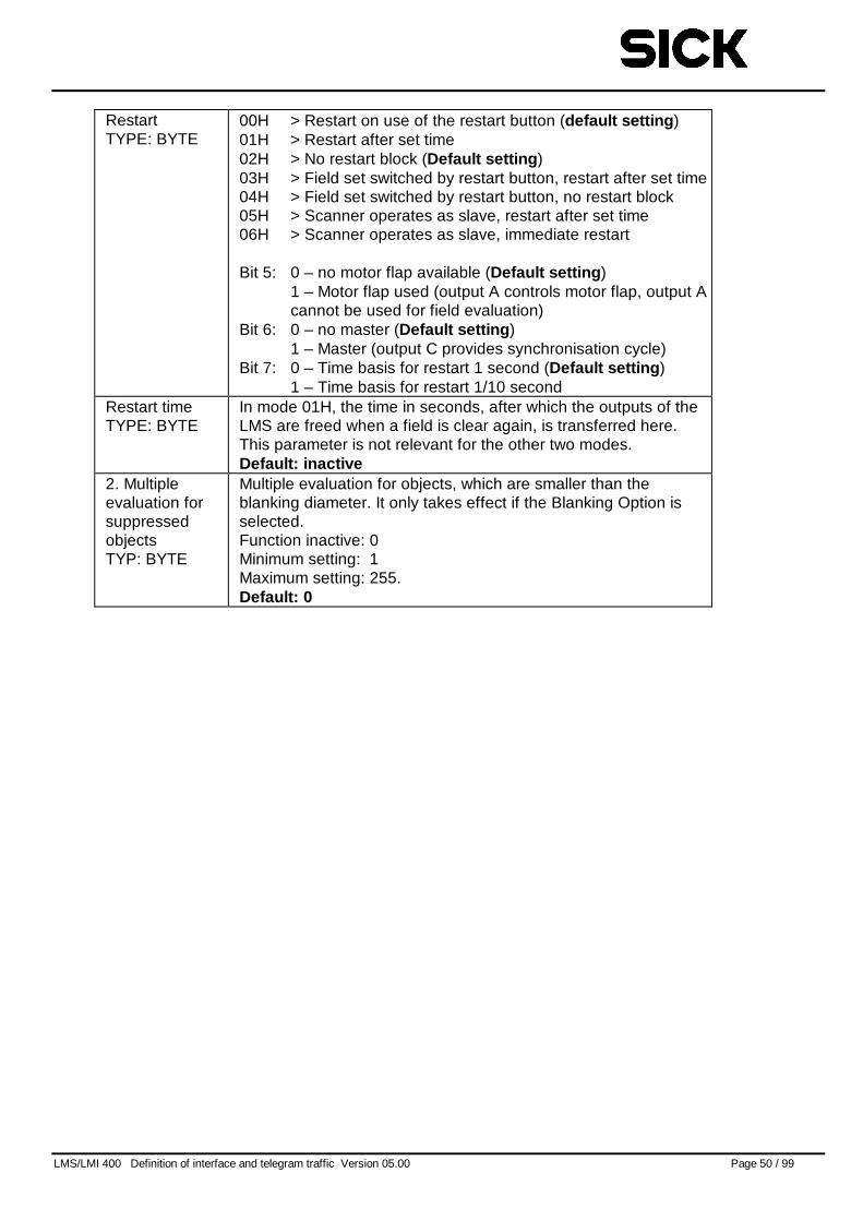
LMS/LMI 400 Definition of interface and telegram traffic Version 05.00 Page 50 / 99
RestartTYPE: BYTE
00H > Restart on use of the restart button (default setting )01H > Restart after set time02H > No restart block (Default setting )03H > Field set switched by restart button, restart after set time04H > Field set switched by restart button, no restart block05H > Scanner operates as slave, restart after set time06H > Scanner operates as slave, immediate restart
Bit 5: 0 – no motor flap available (Default setting )1 – Motor flap used (output A controls motor flap, output Acannot be used for field evaluation)
Bit 6: 0 – no master (Default setting )1 – Master (output C provides synchronisation cycle)
Bit 7: 0 – Time basis for restart 1 second (Default setting )1 – Time basis for restart 1/10 second
Restart timeTYPE: BYTE
In mode 01H, the time in seconds, after which the outputs of theLMS are freed when a field is clear again, is transferred here.This parameter is not relevant for the other two modes.Default: inactive
2. Multipleevaluation forsuppressedobjectsTYP: BYTE
Multiple evaluation for objects, which are smaller than theblanking diameter. It only takes effect if the Blanking Option isselected.Function inactive: 0Minimum setting: 1Maximum setting: 255.Default: 0
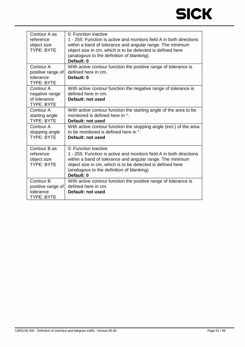
LMS/LMI 400 Definition of interface and telegram traffic Version 05.00 Page 51 / 99
Contour A asreferenceobject sizeTYPE: BYTE
0: Function inactive1 - 255: Function is active and monitors field A in both directionswithin a band of tolerance and angular range. The minimumobject size in cm, which is to be detected is defined here(analogous to the definition of blanking).Default: 0
Contour Apositive range oftoleranceTYPE: BYTE
With active contour function the positive range of tolerance isdefined here in cm.Default: 0
Contour Anegative rangeof toleranceTYPE: BYTE
With active contour function the negative range of tolerance isdefined here in cm.Default: not used
Contour Astarting angleTYPE: BYTE
With active contour function the starting angle of the area to bemonitored is defined here in °.Default: not used
Contour Astopping angleTYPE: BYTE
With active contour function the stopping angle (incl.) of the areato be monitored is defined here in °.Default: not used
Contour B asreferenceobject sizeTYPE: BYTE
0: Function inactive1 - 255: Function is active and monitors field A in both directionswithin a band of tolerance and angular range. The minimumobject size in cm, which is to be detected is defined here(analogous to the definition of blanking).Default: 0
Contour Bpositive range oftoleranceTYPE: BYTE
With active contour function the positive range of tolerance isdefined here in cm.Default: not used
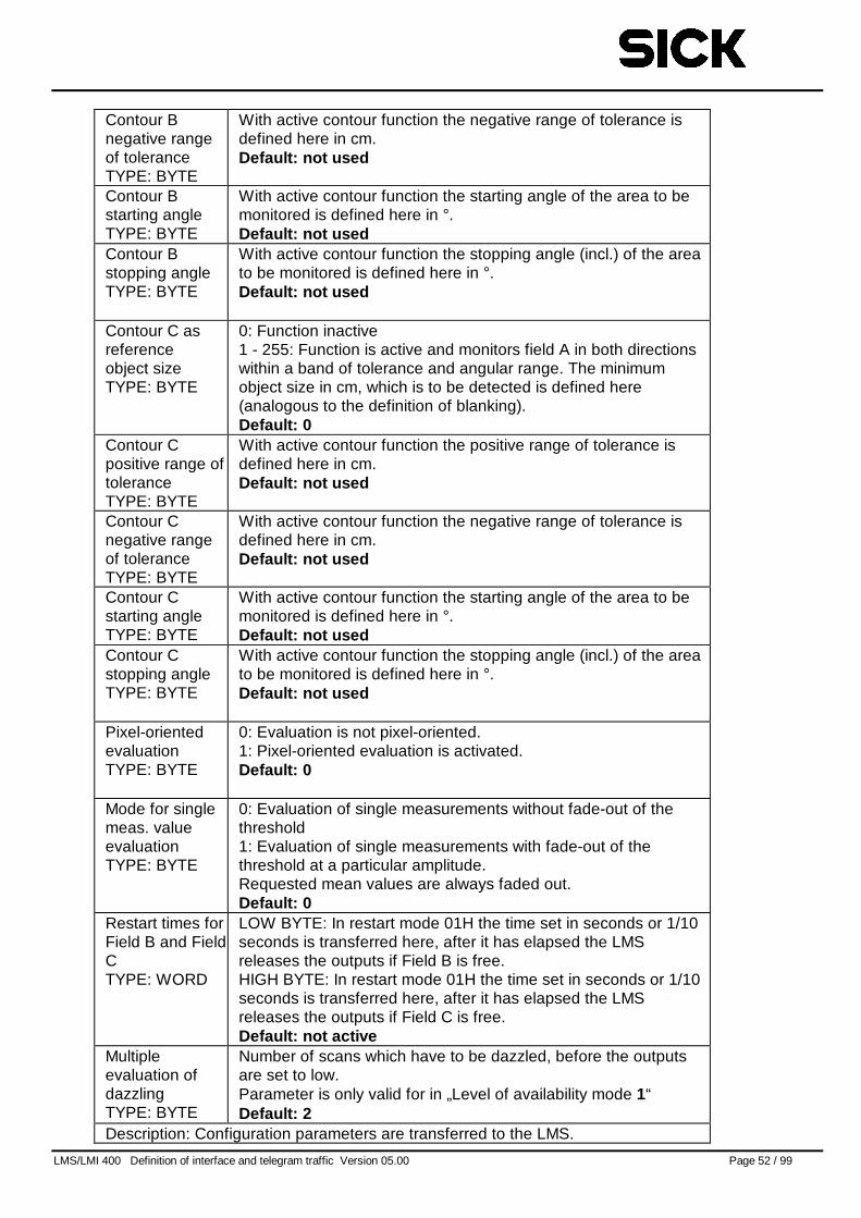
LMS/LMI 400 Definition of interface and telegram traffic Version 05.00 Page 52 / 99
Contour Bnegative rangeof toleranceTYPE: BYTE
With active contour function the negative range of tolerance isdefined here in cm.Default: not used
Contour Bstarting angleTYPE: BYTE
With active contour function the starting angle of the area to bemonitored is defined here in °.Default: not used
Contour Bstopping angleTYPE: BYTE
With active contour function the stopping angle (incl.) of the areato be monitored is defined here in °.Default: not used
Contour C asreferenceobject sizeTYPE: BYTE
0: Function inactive1 - 255: Function is active and monitors field A in both directionswithin a band of tolerance and angular range. The minimumobject size in cm, which is to be detected is defined here(analogous to the definition of blanking).Default: 0
Contour Cpositive range oftoleranceTYPE: BYTE
With active contour function the positive range of tolerance isdefined here in cm.Default: not used
Contour Cnegative rangeof toleranceTYPE: BYTE
With active contour function the negative range of tolerance isdefined here in cm.Default: not used
Contour Cstarting angleTYPE: BYTE
With active contour function the starting angle of the area to bemonitored is defined here in °.Default: not used
Contour Cstopping angleTYPE: BYTE
With active contour function the stopping angle (incl.) of the areato be monitored is defined here in °.Default: not used
Pixel-orientedevaluationTYPE: BYTE
0: Evaluation is not pixel-oriented.1: Pixel-oriented evaluation is activated.Default: 0
Mode for singlemeas. valueevaluationTYPE: BYTE
0: Evaluation of single measurements without fade-out of thethreshold1: Evaluation of single measurements with fade-out of thethreshold at a particular amplitude.Requested mean values are always faded out.Default: 0
Restart times forField B and FieldCTYPE: WORD
LOW BYTE: In restart mode 01H the time set in seconds or 1/10seconds is transferred here, after it has elapsed the LMSreleases the outputs if Field B is free.HIGH BYTE: In restart mode 01H the time set in seconds or 1/10seconds is transferred here, after it has elapsed the LMSreleases the outputs if Field C is free.Default: not active
Multipleevaluation ofdazzlingTYPE: BYTE
Number of scans which have to be dazzled, before the outputsare set to low.Parameter is only valid for in „Level of availability mode 1“Default: 2
Description: Configuration parameters are transferred to the LMS.
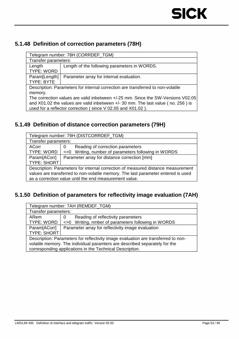
LMS/LMI 400 Definition of interface and telegram traffic Version 05.00 Page 53 / 99
5.1.48 Definition of correction parameters (78H)
Telegram number: 78H (CORRDEF_TGM)Transfer parameters:LengthTYPE: WORD
Length of the following parameters in WORDS.
Param[Length]TYPE: BYTE
Parameter array for internal evaluation.
Description: Parameters for internal correction are transferred to non-volatilememory.The correction values are valid inbetween +/-25 mm. Since the SW-Versions V02.05and X01.02 the values are valid inbetween +/- 30 mm. The last value ( no. 256 ) isused for a reflector correction ( since V 02.05 and X01.02 ).
5.1.49 Definition of distance correction parameters (79H)
Telegram number: 79H (DISTCORRDEF_TGM)Transfer parameters:ACorrTYPE: WORD
0 Reading of correction parameters<>0 Writing, number of parameters following in WORDS
Param[ACorr]TYPE: SHORT
Parameter array for distance correction [mm]
Description: Parameters for internal correction of measured distance measurementvalues are transferred to non-volatile memory. The last parameter entered is usedas a correction value until the end measurement value.
5.1.50 Definition of parameters for reflectivity image evaluation (7AH)
Telegram number: 7AH (REMDEF_TGM)Transfer parameters:ARemTYPE: WORD
0 Reading of reflectivity parameters<>0 Writing, nmber of parameters following in WORDS
Param[ACorr]TYPE: SHORT
Parameter array for reflectivity image evaluation
Description: Parameters for reflectivity image evaluation are transferred to non-volatile memory. The individual paramters are described separately for thecorresponding applications in the Technical Description.
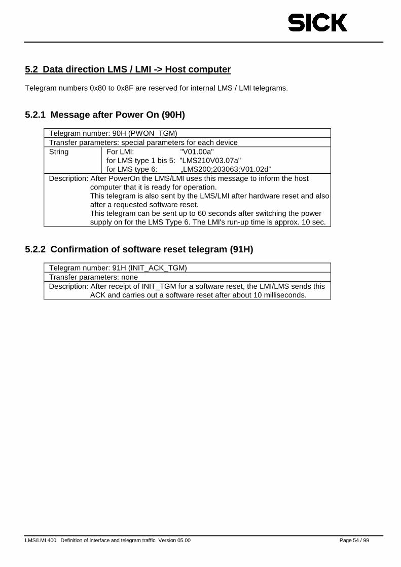
LMS/LMI 400 Definition of interface and telegram traffic Version 05.00 Page 54 / 99
5.2 Data direction LMS / LMI -> Host computer
Telegram numbers 0x80 to 0x8F are reserved for internal LMS / LMI telegrams.
5.2.1 Message after Power On (90H)
Telegram number: 90H (PWON_TGM)Transfer parameters: special parameters for each deviceString For LMI: "V01.00a"
for LMS type 1 bis 5: "LMS210V03.07a"for LMS type 6: „LMS200;203063;V01.02d“
Description: After PowerOn the LMS/LMI uses this message to inform the hostcomputer that it is ready for operation.This telegram is also sent by the LMS/LMI after hardware reset and alsoafter a requested software reset.This telegram can be sent up to 60 seconds after switching the powersupply on for the LMS Type 6. The LMI's run-up time is approx. 10 sec.
5.2.2 Confirmation of software reset telegram (91H)
Telegram number: 91H (INIT_ACK_TGM)Transfer parameters: noneDescription: After receipt of INIT_TGM for a software reset, the LMI/LMS sends this
ACK and carries out a software reset after about 10 milliseconds.
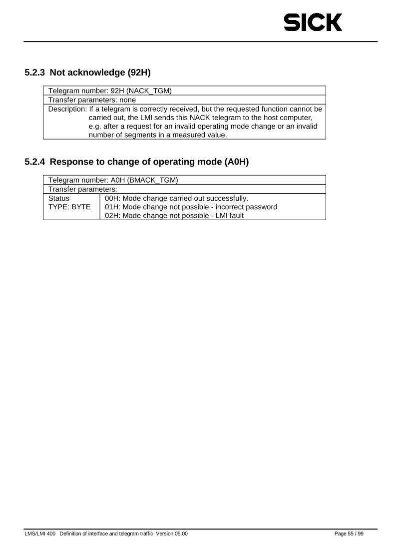
LMS/LMI 400 Definition of interface and telegram traffic Version 05.00 Page 55 / 99
5.2.3 Not acknowledge (92H)
Telegram number: 92H (NACK_TGM)Transfer parameters: noneDescription: If a telegram is correctly received, but the requested function cannot be
carried out, the LMI sends this NACK telegram to the host computer,e.g. after a request for an invalid operating mode change or an invalidnumber of segments in a measured value.
5.2.4 Response to change of operating mode (A0H)
Telegram number: A0H (BMACK_TGM)Transfer parameters:StatusTYPE: BYTE
00H: Mode change carried out successfully.01H: Mode change not possible - incorrect password02H: Mode change not possible - LMI fault
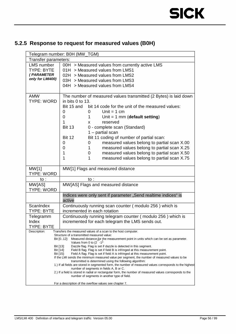
LMS/LMI 400 Definition of interface and telegram traffic Version 05.00 Page 56 / 99
5.2.5 Response to request for measured values (B0H)
Telegram number: B0H (MW_TGM)Transfer parameters:LMS numberTYPE: BYTE( PARAMETERonly for LMI400)
00H > Measured values from currently active LMS01H > Measured values from LMS102H > Measured values from LMS203H > Measured values from LMS304H > Measured values from LMS4
AMWTYPE: WORD
The number of measured values transmitted (2 Bytes) is laid downin bits 0 to 13.Bit 15 and bit 14 code for the unit of the measured values:0 0 Unit = 1 cm0 1 Unit = 1 mm (default setting )1 x reservedBit 13 0 - complete scan (Standard)
1 – partial scanBit 12 Bit 11 coding of number of partial scan:0 0 measured values belong to partial scan X.000 1 measured values belong to partial scan X.251 0 measured values belong to partial scan X.501 1 measured values belong to partial scan X.75
MW[1]TYPE: WORD
MW[1] Flags and measured distance
to : to :MW[AS]TYPE: WORD
MW[AS] Flags and measured distance
Indices were only sent if parameter „Send realtime indices“ isactive
ScanIndexTYPE: BYTE
Continuously running scan counter ( modulo 256 ) which isincremented in each rotation
TelegrammIndexTYPE: BYTE
Continuously running telegram counter ( modulo 256 ) which isincremented for each telegram the LMS sends out.
Description: Transfers the measured values of a scan to the host computer.Structure of a transmitted measured value:Bit [0..12]: Measured distance for the measurement point in units which can be set as parameter.
Values from 0 to (213
-1).
Bit [13]: Dazzle flag. Flag is set if dazzle is detected in this segment.Bit [14]: Field B flag. Flag is set if field B is infringed at this measurement point.Bit [15]: Field A flag. Flag is set if field A is infringed at this measurement point.If the LMI sends the minimum measured value per segment, the number of measured values to be
transmitted is determined using the following algorithm:1.) If all fields are stored in segmented form, the number of measured values corresponds to the highest
number of segments in fields A, B or C.2.) If a field is stored in radial or rectangular form, the number of measured values corresponds to the
number of segments in another type of field.
For a description of the overflow values see chapter 7.
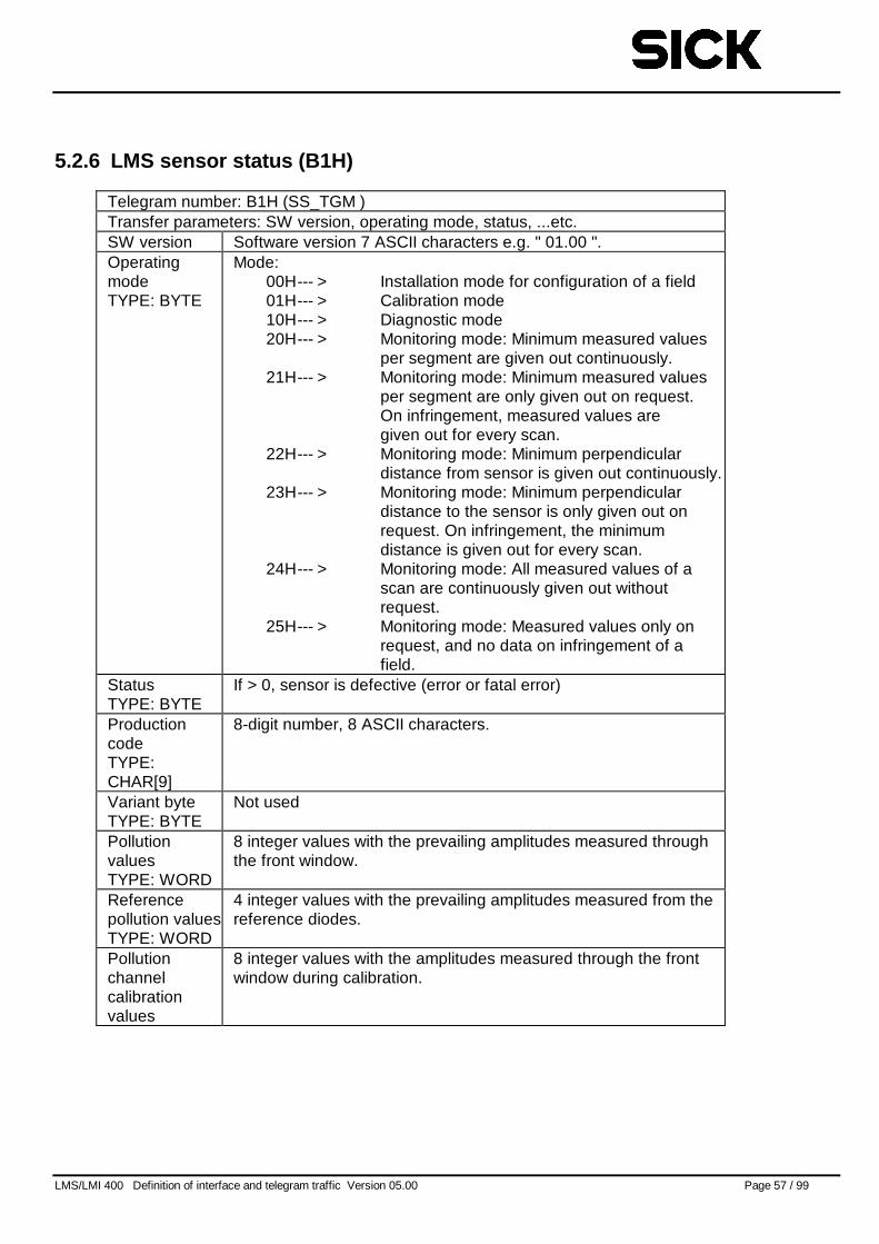
LMS/LMI 400 Definition of interface and telegram traffic Version 05.00 Page 57 / 99
5.2.6 LMS sensor status (B1H)
Telegram number: B1H (SS_TGM )Transfer parameters: SW version, operating mode, status, ...etc.SW version Software version 7 ASCII characters e.g. " 01.00 ".OperatingmodeTYPE: BYTE
Mode:00H--- > Installation mode for configuration of a field01H--- > Calibration mode10H--- > Diagnostic mode20H--- > Monitoring mode: Minimum measured values
per segment are given out continuously.21H--- > Monitoring mode: Minimum measured values
per segment are only given out on request.On infringement, measured values aregiven out for every scan.
22H--- > Monitoring mode: Minimum perpendiculardistance from sensor is given out continuously.
23H--- > Monitoring mode: Minimum perpendiculardistance to the sensor is only given out onrequest. On infringement, the minimumdistance is given out for every scan.
24H--- > Monitoring mode: All measured values of ascan are continuously given out withoutrequest.
25H--- > Monitoring mode: Measured values only onrequest, and no data on infringement of afield.
StatusTYPE: BYTE
If > 0, sensor is defective (error or fatal error)
ProductioncodeTYPE:CHAR[9]
8-digit number, 8 ASCII characters.
Variant byteTYPE: BYTE
Not used
PollutionvaluesTYPE: WORD
8 integer values with the prevailing amplitudes measured throughthe front window.
Referencepollution valuesTYPE: WORD
4 integer values with the prevailing amplitudes measured from thereference diodes.
Pollutionchannelcalibrationvalues
8 integer values with the amplitudes measured through the frontwindow during calibration.
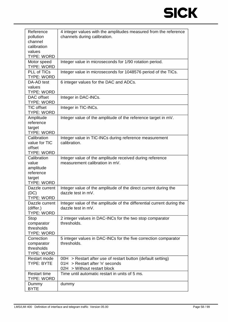
LMS/LMI 400 Definition of interface and telegram traffic Version 05.00 Page 58 / 99
ReferencepollutionchannelcalibrationvaluesTYPE: WORD
4 integer values with the amplitudes measured from the referencechannels during calibration.
Motor speedTYPE: WORD
Integer value in microseconds for 1/90 rotation period.
PLL of TICsTYPE: WORD
Integer value in microseconds for 1048576 period of the TICs.
DA-AD testvaluesTYPE: WORD
6 integer values for the DAC and ADCs.
DAC offsetTYPE: WORD
Integer in DAC-INCs.
TIC offsetTYPE: WORD
Integer in TIC-INCs.
AmplitudereferencetargetTYPE: WORD
Integer value of the amplitude of the reference target in mV.
Calibrationvalue for TICoffsetTYPE: WORD
Integer value in TIC-INCs during reference measurementcalibration.
CalibrationvalueamplitudereferencetargetTYPE: WORD
Integer value of the amplitude received during referencemeasurement calibration in mV.
Dazzle current(DC)TYPE: WORD
Integer value of the amplitude of the direct current during thedazzle test in mV.
Dazzle current(differ.)TYPE: WORD
Integer value of the amplitude of the differential current during thedazzle test in mV.
StopcomparatorthresholdsTYPE: WORD
2 integer values in DAC-INCs for the two stop comparatorthresholds.
CorrectioncomparatorthresholdsTYPE: WORD
5 integer values in DAC-INCs for the five correction comparatorthresholds.
Restart modeTYPE: BYTE
00H > Restart after use of restart button (default setting)01H > Restart after 'n' seconds02H > Without restart block
Restart timeTYPE: WORD
Time until automatic restart in units of 5 ms.
DummyBYTE
dummy
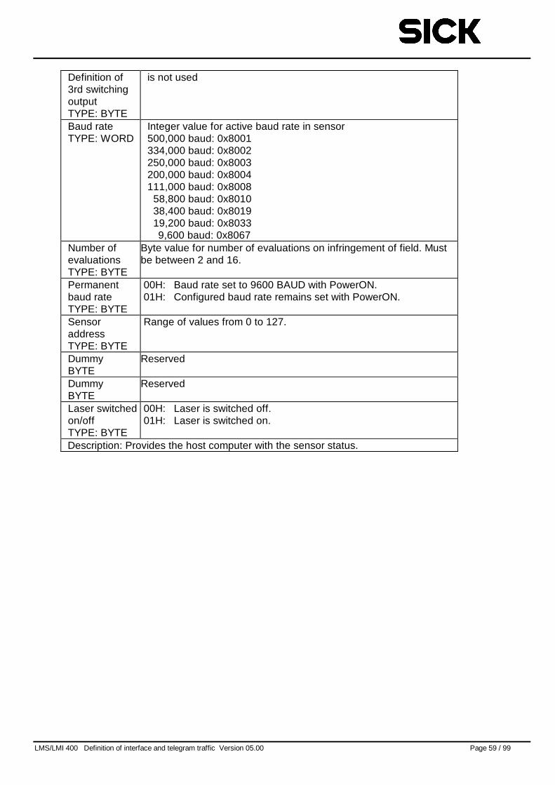
LMS/LMI 400 Definition of interface and telegram traffic Version 05.00 Page 59 / 99
Definition of3rd switchingoutputTYPE: BYTE
is not used
Baud rateTYPE: WORD
Integer value for active baud rate in sensor500,000 baud: 0x8001334,000 baud: 0x8002250,000 baud: 0x8003200,000 baud: 0x8004111,000 baud: 0x8008
58,800 baud: 0x801038,400 baud: 0x801919,200 baud: 0x80339,600 baud: 0x8067
Number ofevaluationsTYPE: BYTE
Byte value for number of evaluations on infringement of field. Mustbe between 2 and 16.
Permanentbaud rateTYPE: BYTE
00H: Baud rate set to 9600 BAUD with PowerON.01H: Configured baud rate remains set with PowerON.
SensoraddressTYPE: BYTE
Range of values from 0 to 127.
DummyBYTE
Reserved
DummyBYTE
Reserved
Laser switchedon/offTYPE: BYTE
00H: Laser is switched off.01H: Laser is switched on.
Description: Provides the host computer with the sensor status.
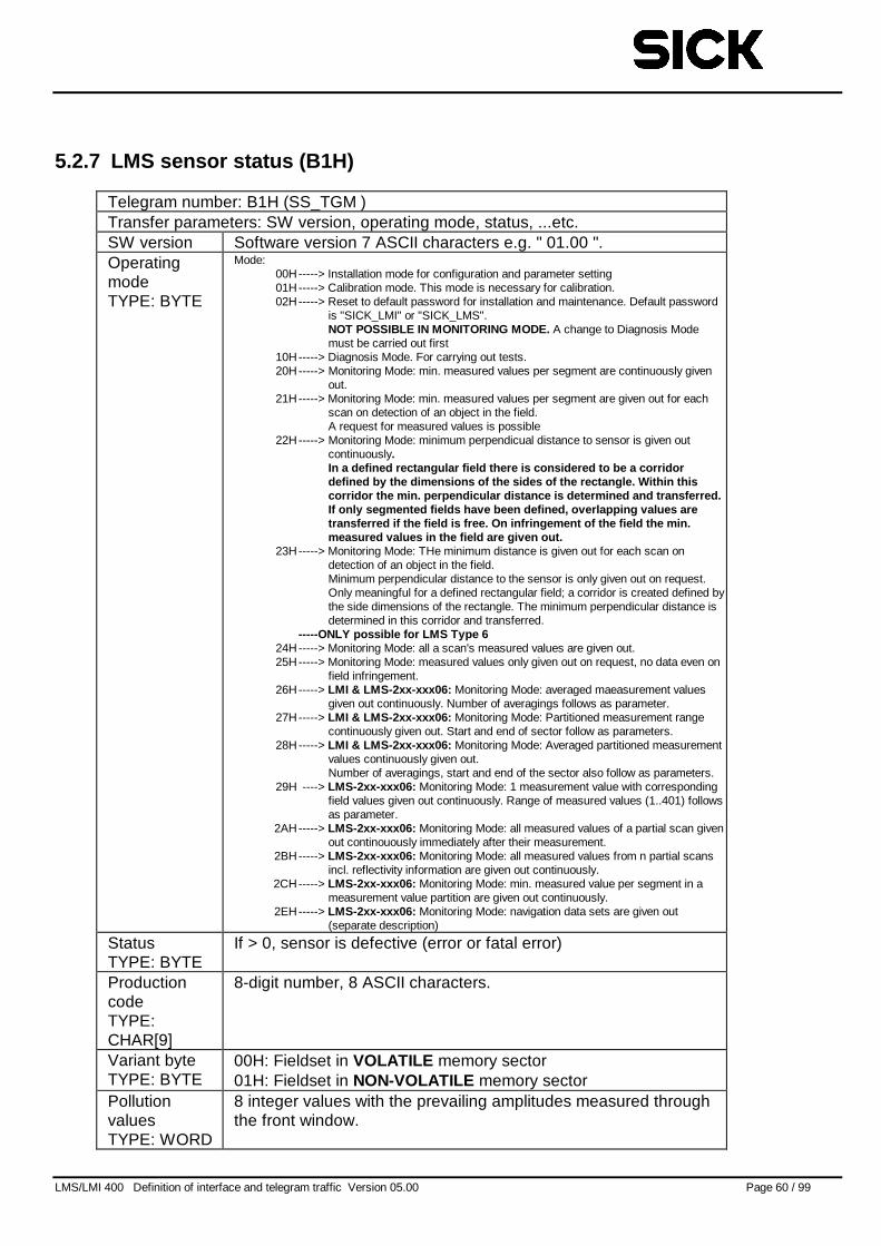
LMS/LMI 400 Definition of interface and telegram traffic Version 05.00 Page 60 / 99
5.2.7 LMS sensor status (B1H)
Telegram number: B1H (SS_TGM )Transfer parameters: SW version, operating mode, status, ...etc.SW version Software version 7 ASCII characters e.g. " 01.00 ".OperatingmodeTYPE: BYTE
Mode:00H-----> Installation mode for configuration and parameter setting01H-----> Calibration mode. This mode is necessary for calibration.02H-----> Reset to default password for installation and maintenance. Default password
is "SICK_LMI" or "SICK_LMS".NOT POSSIBLE IN MONITORING MODE. A change to Diagnosis Modemust be carried out first
10H-----> Diagnosis Mode. For carrying out tests.20H-----> Monitoring Mode: min. measured values per segment are continuously given
out.21H-----> Monitoring Mode: min. measured values per segment are given out for each
scan on detection of an object in the field.A request for measured values is possible
22H-----> Monitoring Mode: minimum perpendicual distance to sensor is given outcontinuously.In a defined rectangular field there is considered to be a corridordefined by the dimensions of the sides of the rectangle. Within thiscorridor the min. perpendicular distance is determined and transferred.If only segmented fields have been defined, overlapping values aretransferred if the field is free. On infringement of the field the min.measured values in the field are given out.
23H-----> Monitoring Mode: THe minimum distance is given out for each scan ondetection of an object in the field.Minimum perpendicular distance to the sensor is only given out on request.Only meaningful for a defined rectangular field; a corridor is created defined bythe side dimensions of the rectangle. The minimum perpendicular distance isdetermined in this corridor and transferred.
-----ONLY possible for LMS Type 624H-----> Monitoring Mode: all a scan's measured values are given out.25H-----> Monitoring Mode: measured values only given out on request, no data even on
field infringement.26H-----> LMI & LMS-2xx-xxx06: Monitoring Mode: averaged maeasurement values
given out continuously. Number of averagings follows as parameter.27H-----> LMI & LMS-2xx-xxx06: Monitoring Mode: Partitioned measurement range
continuously given out. Start and end of sector follow as parameters.28H-----> LMI & LMS-2xx-xxx06: Monitoring Mode: Averaged partitioned measurement
values continuously given out.Number of averagings, start and end of the sector also follow as parameters.
29H ----> LMS-2xx-xxx06: Monitoring Mode: 1 measurement value with correspondingfield values given out continuously. Range of measured values (1..401) followsas parameter.
2AH-----> LMS-2xx-xxx06: Monitoring Mode: all measured values of a partial scan givenout continouously immediately after their measurement.
2BH-----> LMS-2xx-xxx06: Monitoring Mode: all measured values from n partial scansincl. reflectivity information are given out continuously.
2CH-----> LMS-2xx-xxx06: Monitoring Mode: min. measured value per segment in ameasurement value partition are given out continuously.
2EH-----> LMS-2xx-xxx06: Monitoring Mode: navigation data sets are given out(separate description)
StatusTYPE: BYTE
If > 0, sensor is defective (error or fatal error)
ProductioncodeTYPE:CHAR[9]
8-digit number, 8 ASCII characters.
Variant byteTYPE: BYTE
00H: Fieldset in VOLATILE memory sector01H: Fieldset in NON-VOLATILE memory sector
PollutionvaluesTYPE: WORD
8 integer values with the prevailing amplitudes measured throughthe front window.
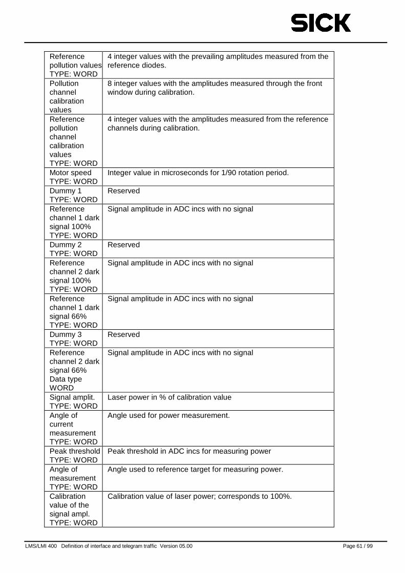
LMS/LMI 400 Definition of interface and telegram traffic Version 05.00 Page 61 / 99
Referencepollution valuesTYPE: WORD
4 integer values with the prevailing amplitudes measured from thereference diodes.
Pollutionchannelcalibrationvalues
8 integer values with the amplitudes measured through the frontwindow during calibration.
ReferencepollutionchannelcalibrationvaluesTYPE: WORD
4 integer values with the amplitudes measured from the referencechannels during calibration.
Motor speedTYPE: WORD
Integer value in microseconds for 1/90 rotation period.
Dummy 1TYPE: WORD
Reserved
Referencechannel 1 darksignal 100%TYPE: WORD
Signal amplitude in ADC incs with no signal
Dummy 2TYPE: WORD
Reserved
Referencechannel 2 darksignal 100%TYPE: WORD
Signal amplitude in ADC incs with no signal
Referencechannel 1 darksignal 66%TYPE: WORD
Signal amplitude in ADC incs with no signal
Dummy 3TYPE: WORD
Reserved
Referencechannel 2 darksignal 66%Data typeWORD
Signal amplitude in ADC incs with no signal
Signal amplit.TYPE: WORD
Laser power in % of calibration value
Angle ofcurrentmeasurementTYPE: WORD
Angle used for power measurement.
Peak thresholdTYPE: WORD
Peak threshold in ADC incs for measuring power
Angle ofmeasurementTYPE: WORD
Angle used to reference target for measuring power.
Calibrationvalue of thesignal ampl.TYPE: WORD
Calibration value of laser power; corresponds to 100%.
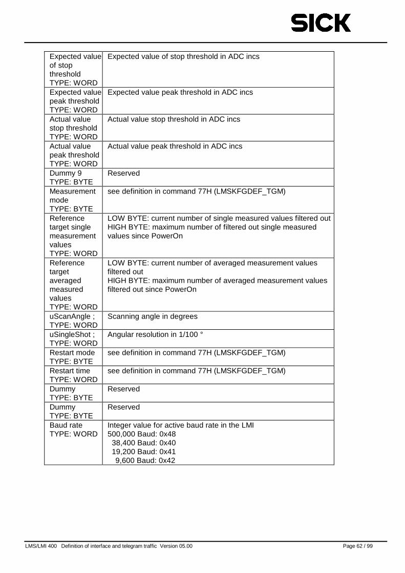
LMS/LMI 400 Definition of interface and telegram traffic Version 05.00 Page 62 / 99
Expected valueof stopthresholdTYPE: WORD
Expected value of stop threshold in ADC incs
Expected valuepeak thresholdTYPE: WORD
Expected value peak threshold in ADC incs
Actual valuestop thresholdTYPE: WORD
Actual value stop threshold in ADC incs
Actual valuepeak thresholdTYPE: WORD
Actual value peak threshold in ADC incs
Dummy 9TYPE: BYTE
Reserved
MeasurementmodeTYPE: BYTE
see definition in command 77H (LMSKFGDEF_TGM)
Referencetarget singlemeasurementvaluesTYPE: WORD
LOW BYTE: current number of single measured values filtered outHIGH BYTE: maximum number of filtered out single measuredvalues since PowerOn
ReferencetargetaveragedmeasuredvaluesTYPE: WORD
LOW BYTE: current number of averaged measurement valuesfiltered outHIGH BYTE: maximum number of averaged measurement valuesfiltered out since PowerOn
uScanAngle ;TYPE: WORD
Scanning angle in degrees
uSingleShot ;TYPE: WORD
Angular resolution in 1/100 °
Restart modeTYPE: BYTE
see definition in command 77H (LMSKFGDEF_TGM)
Restart timeTYPE: WORD
see definition in command 77H (LMSKFGDEF_TGM)
DummyTYPE: BYTE
Reserved
DummyTYPE: BYTE
Reserved
Baud rateTYPE: WORD
Integer value for active baud rate in the LMI500,000 Baud: 0x48
38,400 Baud: 0x4019,200 Baud: 0x419,600 Baud: 0x42
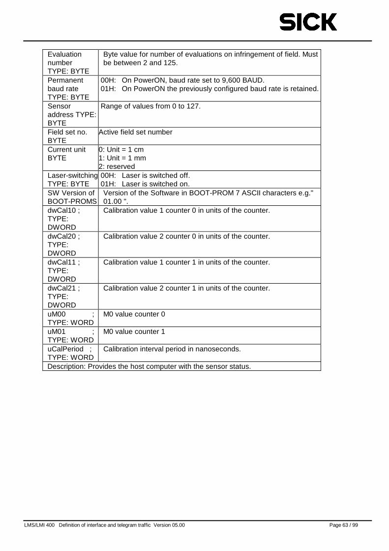
LMS/LMI 400 Definition of interface and telegram traffic Version 05.00 Page 63 / 99
EvaluationnumberTYPE: BYTE
Byte value for number of evaluations on infringement of field. Mustbe between 2 and 125.
Permanentbaud rateTYPE: BYTE
00H: On PowerON, baud rate set to 9,600 BAUD.01H: On PowerON the previously configured baud rate is retained.
Sensoraddress TYPE:BYTE
Range of values from 0 to 127.
Field set no.BYTE
Active field set number
Current unitBYTE
0: Unit = 1 cm1: Unit = 1 mm2: reserved
Laser-switchingTYPE: BYTE
00H: Laser is switched off.01H: Laser is switched on.
SW Version ofBOOT-PROMS
Version of the Software in BOOT-PROM 7 ASCII characters e.g."01.00 ".
dwCal10 ;TYPE:DWORD
Calibration value 1 counter 0 in units of the counter.
dwCal20 ;TYPE:DWORD
Calibration value 2 counter 0 in units of the counter.
dwCal11 ;TYPE:DWORD
Calibration value 1 counter 1 in units of the counter.
dwCal21 ;TYPE:DWORD
Calibration value 2 counter 1 in units of the counter.
uM00 ;TYPE: WORD
M0 value counter 0
uM01 ;TYPE: WORD
M0 value counter 1
uCalPeriod ;TYPE: WORD
Calibration interval period in nanoseconds.
Description: Provides the host computer with the sensor status.
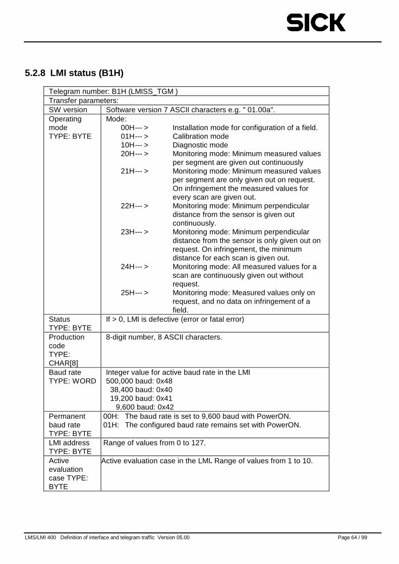
LMS/LMI 400 Definition of interface and telegram traffic Version 05.00 Page 64 / 99
5.2.8 LMI status (B1H)
Telegram number: B1H (LMISS_TGM )Transfer parameters:SW version Software version 7 ASCII characters e.g. " 01.00a".OperatingmodeTYPE: BYTE
Mode:00H--- > Installation mode for configuration of a field.01H--- > Calibration mode10H--- > Diagnostic mode20H--- > Monitoring mode: Minimum measured values
per segment are given out continuously21H--- > Monitoring mode: Minimum measured values
per segment are only given out on request.On infringement the measured values forevery scan are given out.
22H--- > Monitoring mode: Minimum perpendiculardistance from the sensor is given outcontinuously.
23H--- > Monitoring mode: Minimum perpendiculardistance from the sensor is only given out onrequest. On infringement, the minimumdistance for each scan is given out.
24H--- > Monitoring mode: All measured values for ascan are continuously given out withoutrequest.
25H--- > Monitoring mode: Measured values only onrequest, and no data on infringement of afield.
StatusTYPE: BYTE
If > 0, LMI is defective (error or fatal error)
ProductioncodeTYPE:CHAR[8]
8-digit number, 8 ASCII characters.
Baud rateTYPE: WORD
Integer value for active baud rate in the LMI500,000 baud: 0x48
38,400 baud: 0x4019,200 baud: 0x41
9,600 baud: 0x42Permanentbaud rateTYPE: BYTE
00H: The baud rate is set to 9,600 baud with PowerON.01H: The configured baud rate remains set with PowerON.
LMI addressTYPE: BYTE
Range of values from 0 to 127.
Activeevaluationcase TYPE:BYTE
Active evaluation case in the LMI. Range of values from 1 to 10.
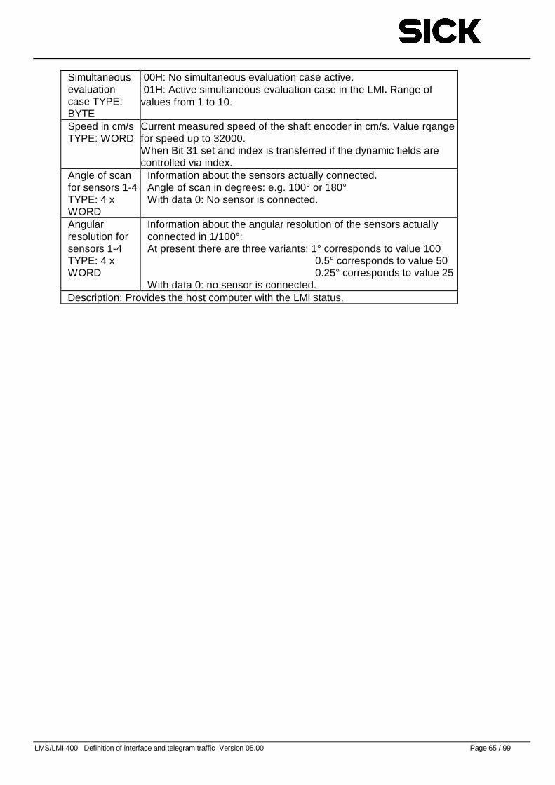
LMS/LMI 400 Definition of interface and telegram traffic Version 05.00 Page 65 / 99
Simultaneousevaluationcase TYPE:BYTE
00H: No simultaneous evaluation case active.01H: Active simultaneous evaluation case in the LMI. Range of
values from 1 to 10.
Speed in cm/sTYPE: WORD
Current measured speed of the shaft encoder in cm/s. Value rqangefor speed up to 32000.When Bit 31 set and index is transferred if the dynamic fields arecontrolled via index.
Angle of scanfor sensors 1-4TYPE: 4 xWORD
Information about the sensors actually connected.Angle of scan in degrees: e.g. 100° or 180°With data 0: No sensor is connected.
Angularresolution forsensors 1-4TYPE: 4 xWORD
Information about the angular resolution of the sensors actuallyconnected in 1/100°:At present there are three variants: 1° corresponds to value 100
0.5° corresponds to value 500.25° corresponds to value 25
With data 0: no sensor is connected.Description: Provides the host computer with the LMI Status.
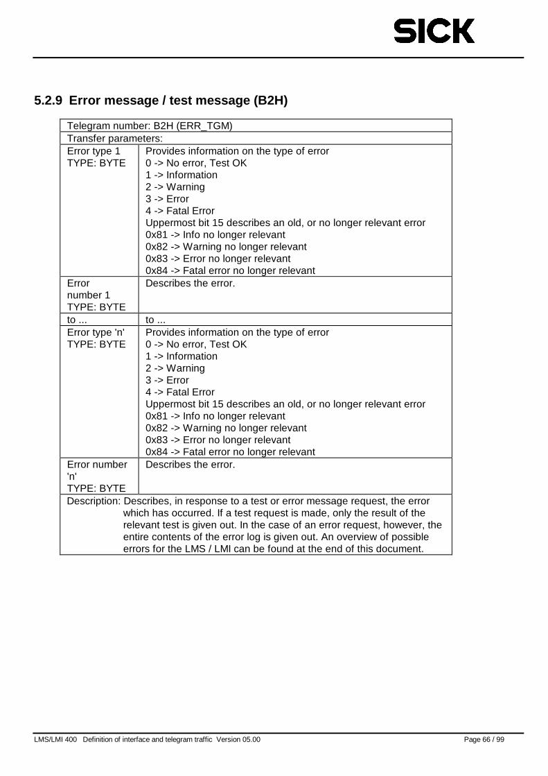
LMS/LMI 400 Definition of interface and telegram traffic Version 05.00 Page 66 / 99
5.2.9 Error message / test message (B2H)
Telegram number: B2H (ERR_TGM)Transfer parameters:Error type 1TYPE: BYTE
Provides information on the type of error0 -> No error, Test OK1 -> Information2 -> Warning3 -> Error4 -> Fatal ErrorUppermost bit 15 describes an old, or no longer relevant error0x81 -> Info no longer relevant0x82 -> Warning no longer relevant0x83 -> Error no longer relevant0x84 -> Fatal error no longer relevant
Errornumber 1TYPE: BYTE
Describes the error.
to ... to ...Error type 'n'TYPE: BYTE
Provides information on the type of error0 -> No error, Test OK1 -> Information2 -> Warning3 -> Error4 -> Fatal ErrorUppermost bit 15 describes an old, or no longer relevant error0x81 -> Info no longer relevant0x82 -> Warning no longer relevant0x83 -> Error no longer relevant0x84 -> Fatal error no longer relevant
Error number'n'TYPE: BYTE
Describes the error.
Description: Describes, in response to a test or error message request, the errorwhich has occurred. If a test request is made, only the result of therelevant test is given out. In the case of an error request, however, theentire contents of the error log is given out. An overview of possibleerrors for the LMS / LMI can be found at the end of this document.
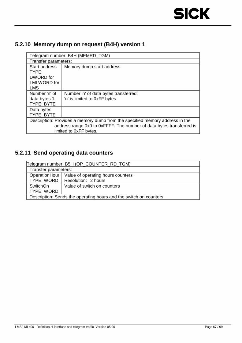
LMS/LMI 400 Definition of interface and telegram traffic Version 05.00 Page 67 / 99
5.2.10 Memory dump on request (B4H) version 1
Telegram number: B4H (MEMRD_TGM)Transfer parameters:Start addressTYPE:DWORD forLMI WORD forLMS
Memory dump start address
Number 'n' ofdata bytes 1TYPE: BYTE
Number 'n' of data bytes transferred;'n' is limited to 0xFF bytes.
Data bytesTYPE: BYTEDescription: Provides a memory dump from the specified memory address in the
address range 0x0 to 0xFFFF. The number of data bytes transferred islimited to 0xFF bytes.
5.2.11 Send operating data counters
Telegram number: B5H (OP_COUNTER_RD_TGM)Transfer parameters:OperationHourTYPE: WORD
Value of operating hours countersResolution: 2 hours
SwitchOnTYPE: WORD
Value of switch on counters
Description: Sends the operating hours and the switch on counters
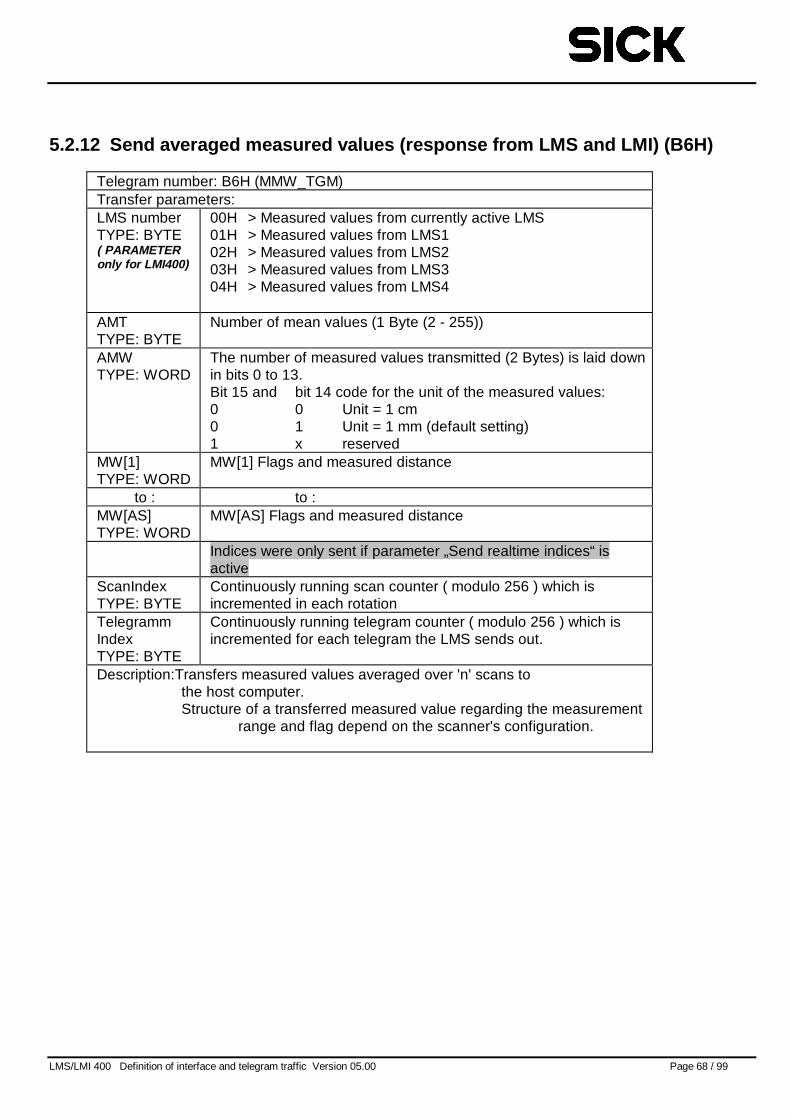
LMS/LMI 400 Definition of interface and telegram traffic Version 05.00 Page 68 / 99
5.2.12 Send averaged measured values (response from LMS and LMI) (B6H)
Telegram number: B6H (MMW_TGM)Transfer parameters:LMS numberTYPE: BYTE( PARAMETERonly for LMI400)
00H > Measured values from currently active LMS01H > Measured values from LMS102H > Measured values from LMS203H > Measured values from LMS304H > Measured values from LMS4
AMTTYPE: BYTE
Number of mean values (1 Byte (2 - 255))
AMWTYPE: WORD
The number of measured values transmitted (2 Bytes) is laid downin bits 0 to 13.Bit 15 and bit 14 code for the unit of the measured values:0 0 Unit = 1 cm0 1 Unit = 1 mm (default setting)1 x reserved
MW[1]TYPE: WORD
MW[1] Flags and measured distance
to : to :MW[AS]TYPE: WORD
MW[AS] Flags and measured distance
Indices were only sent if parameter „Send realtime indices“ isactive
ScanIndexTYPE: BYTE
Continuously running scan counter ( modulo 256 ) which isincremented in each rotation
TelegrammIndexTYPE: BYTE
Continuously running telegram counter ( modulo 256 ) which isincremented for each telegram the LMS sends out.
Description:Transfers measured values averaged over 'n' scans tothe host computer.Structure of a transferred measured value regarding the measurement
range and flag depend on the scanner's configuration.
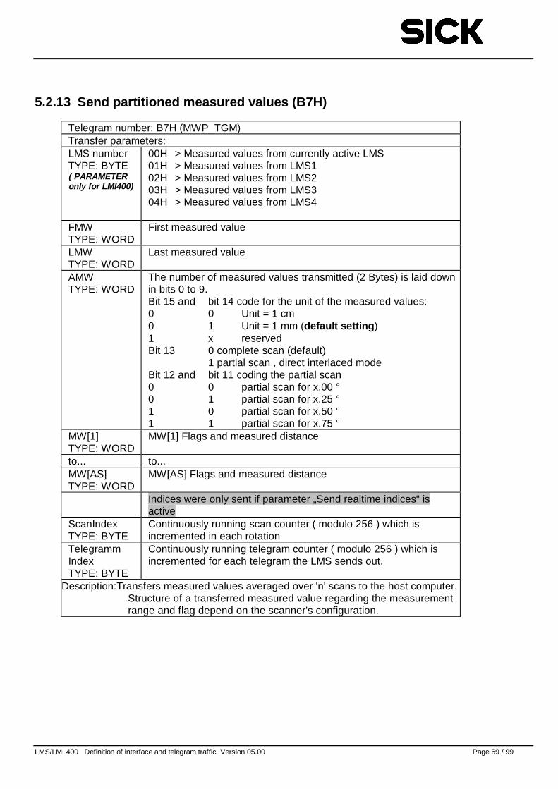
LMS/LMI 400 Definition of interface and telegram traffic Version 05.00 Page 69 / 99
5.2.13 Send partitioned measured values (B7H)
Telegram number: B7H (MWP_TGM)Transfer parameters:LMS numberTYPE: BYTE( PARAMETERonly for LMI400)
00H > Measured values from currently active LMS01H > Measured values from LMS102H > Measured values from LMS203H > Measured values from LMS304H > Measured values from LMS4
FMWTYPE: WORD
First measured value
LMWTYPE: WORD
Last measured value
AMWTYPE: WORD
The number of measured values transmitted (2 Bytes) is laid downin bits 0 to 9.Bit 15 and bit 14 code for the unit of the measured values:0 0 Unit = 1 cm0 1 Unit = 1 mm (default setting )1 x reservedBit 13 0 complete scan (default)
1 partial scan , direct interlaced modeBit 12 and bit 11 coding the partial scan0 0 partial scan for x.00 °0 1 partial scan for x.25 °1 0 partial scan for x.50 °1 1 partial scan for x.75 °
MW[1]TYPE: WORD
MW[1] Flags and measured distance
to... to...MW[AS]TYPE: WORD
MW[AS] Flags and measured distance
Indices were only sent if parameter „Send realtime indices“ isactive
ScanIndexTYPE: BYTE
Continuously running scan counter ( modulo 256 ) which isincremented in each rotation
TelegrammIndexTYPE: BYTE
Continuously running telegram counter ( modulo 256 ) which isincremented for each telegram the LMS sends out.
Description:Transfers measured values averaged over 'n' scans to the host computer.Structure of a transferred measured value regarding the measurementrange and flag depend on the scanner's configuration.
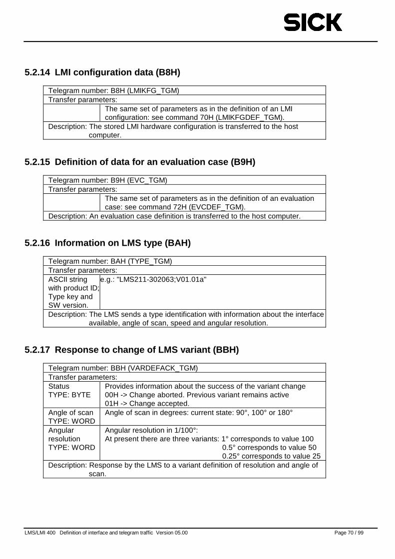
LMS/LMI 400 Definition of interface and telegram traffic Version 05.00 Page 70 / 99
5.2.14 LMI configuration data (B8H)
Telegram number: B8H (LMIKFG_TGM)Transfer parameters:
The same set of parameters as in the definition of an LMIconfiguration: see command 70H (LMIKFGDEF_TGM).
Description: The stored LMI hardware configuration is transferred to the hostcomputer.
5.2.15 Definition of data for an evaluation case (B9H)
Telegram number: B9H (EVC_TGM)Transfer parameters:
The same set of parameters as in the definition of an evaluationcase: see command 72H (EVCDEF_TGM).
Description: An evaluation case definition is transferred to the host computer.
5.2.16 Information on LMS type (BAH)
Telegram number: BAH (TYPE_TGM)Transfer parameters:ASCII stringwith product ID;Type key andSW version.
e.g.: "LMS211-302063;V01.01a"
Description: The LMS sends a type identification with information about the interfaceavailable, angle of scan, speed and angular resolution.
5.2.17 Response to change of LMS variant (BBH)
Telegram number: BBH (VARDEFACK_TGM)Transfer parameters:StatusTYPE: BYTE
Provides information about the success of the variant change00H -> Change aborted. Previous variant remains active01H -> Change accepted.
Angle of scanTYPE: WORD
Angle of scan in degrees: current state: 90°, 100° or 180°
AngularresolutionTYPE: WORD
Angular resolution in 1/100°:At present there are three variants: 1° corresponds to value 100
0.5° corresponds to value 500.25° corresponds to value 25
Description: Response by the LMS to a variant definition of resolution and angle ofscan.
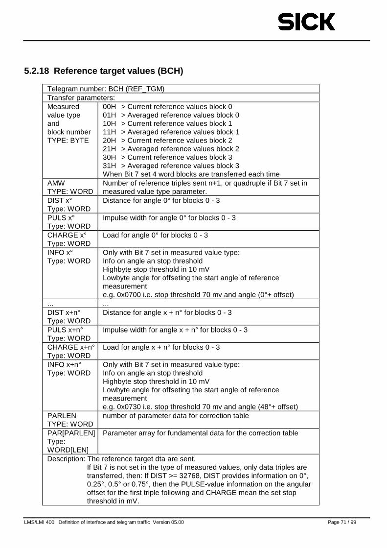
LMS/LMI 400 Definition of interface and telegram traffic Version 05.00 Page 71 / 99
5.2.18 Reference target values (BCH)
Telegram number: BCH (REF_TGM)Transfer parameters:Measuredvalue typeandblock numberTYPE: BYTE
00H > Current reference values block 001H > Averaged reference values block 010H > Current reference values block 111H > Averaged reference values block 120H > Current reference values block 221H > Averaged reference values block 230H > Current reference values block 331H > Averaged reference values block 3When Bit 7 set 4 word blocks are transferred each time
AMWTYPE: WORD
Number of reference triples sent n+1, or quadruple if Bit 7 set inmeasured value type parameter.
DIST x°Type: WORD
Distance for angle 0° for blocks 0 - 3
PULS x°Type: WORD
Impulse width for angle 0° for blocks 0 - 3
CHARGE x°Type: WORD
Load for angle 0° for blocks 0 - 3
INFO x°Type: WORD
Only with Bit 7 set in measured value type:Info on angle an stop thresholdHighbyte stop threshold in 10 mVLowbyte angle for offseting the start angle of referencemeasuremente.g. 0x0700 i.e. stop threshold 70 mv and angle (0°+ offset)
... ...DIST x+n°Type: WORD
Distance for angle x + n° for blocks 0 - 3
PULS x+n°Type: WORD
Impulse width for angle x + n° for blocks 0 - 3
CHARGE x+n°Type: WORD
Load for angle x + n° for blocks 0 - 3
INFO x+n°Type: WORD
Only with Bit 7 set in measured value type:Info on angle an stop thresholdHighbyte stop threshold in 10 mVLowbyte angle for offseting the start angle of referencemeasuremente.g. 0x0730 i.e. stop threshold 70 mv and angle (48°+ offset)
PARLENTYPE: WORD
number of parameter data for correction table
PAR[PARLEN]Type:WORD[LEN]
Parameter array for fundamental data for the correction table
Description: The reference target dta are sent.If Bit 7 is not set in the type of measured values, only data triples aretransferred, then: If DIST >= 32768, DIST provides information on 0°,0.25°, 0.5° or 0.75°, then the PULSE-value information on the angularoffset for the first triple following and CHARGE mean the set stopthreshold in mV.
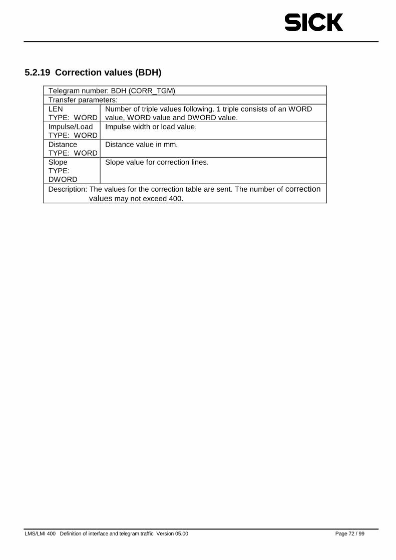
LMS/LMI 400 Definition of interface and telegram traffic Version 05.00 Page 72 / 99
5.2.19 Correction values (BDH)
Telegram number: BDH (CORR_TGM)Transfer parameters:LENTYPE: WORD
Number of triple values following. 1 triple consists of an WORDvalue, WORD value and DWORD value.
Impulse/LoadTYPE: WORD
Impulse width or load value.
DistanceTYPE: WORD
Distance value in mm.
SlopeTYPE:DWORD
Slope value for correction lines.
Description: The values for the correction table are sent. The number of correctionvalues may not exceed 400.
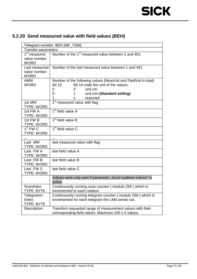
LMS/LMI 400 Definition of interface and telegram traffic Version 05.00 Page 73 / 99
5.2.20 Send measured value with field values (BEH)
Telegram number: BEH (MF_TGM)Transfer parameters:1st measuredvalue numberWORD
Number of the 1st measured value between 1 and 401
Last measuredvalue numberWORD
Number of the last measured value between 1 and 401
AMWWORD
Number of the following values (MeasVal and FieldVal in total)Bit 15 Bit 14 code the unit of the values:0 0 unit cm0 1 unit mm (Standard setting)1 x reserved
1st MWTYPE: WORD
1st measured value with flag
1st FW ATYPE: WORD
1st field value A
1st FW BTYPE: WORD
1st field value B
1st FW CTYPE: WORD
1st field value C
... ...Last MWTYPE: WORD
last measured value with flag
Last FW ATYPE: WORD
last field value A
Last FW BTYPE: WORD
last field value B
Last FW CTYPE: WORD
last field value C
Indices were only sent if parameter „Send realtime indices“ isactive
ScanIndexTYPE: BYTE
Continuously running scan counter ( modulo 256 ) which isincremented in each rotation
TelegrammIndexTYPE: BYTE
Continuously running telegram counter ( modulo 256 ) which isincremented for each telegram the LMS sends out.
Description: Transfers requested range of measurement values with theircorresponding field values. Maximum 100 x 4 values.
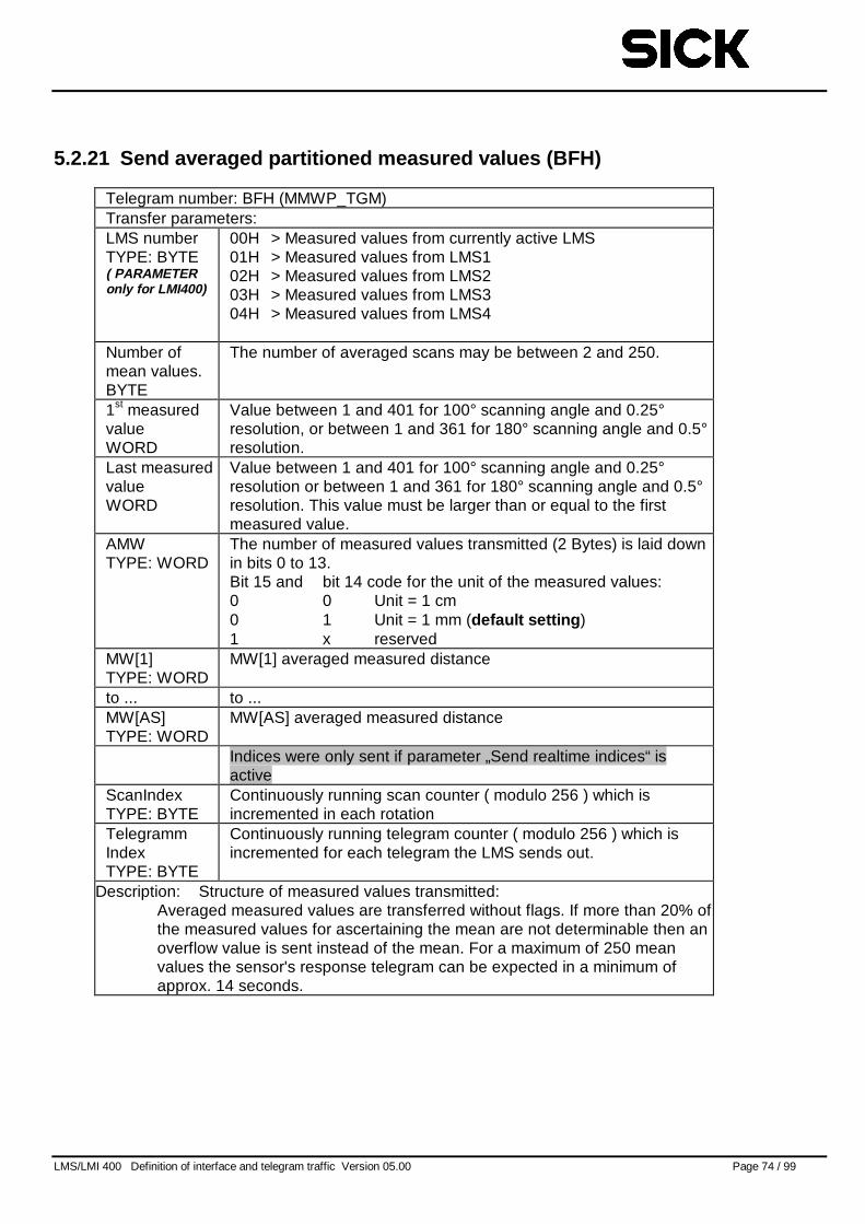
LMS/LMI 400 Definition of interface and telegram traffic Version 05.00 Page 74 / 99
5.2.21 Send averaged partitioned measured values (BFH)
Telegram number: BFH (MMWP_TGM)Transfer parameters:LMS numberTYPE: BYTE( PARAMETERonly for LMI400)
00H > Measured values from currently active LMS01H > Measured values from LMS102H > Measured values from LMS203H > Measured values from LMS304H > Measured values from LMS4
Number ofmean values.BYTE
The number of averaged scans may be between 2 and 250.
1st measuredvalueWORD
Value between 1 and 401 for 100° scanning angle and 0.25°resolution, or between 1 and 361 for 180° scanning angle and 0.5°resolution.
Last measuredvalueWORD
Value between 1 and 401 for 100° scanning angle and 0.25°resolution or between 1 and 361 for 180° scanning angle and 0.5°resolution. This value must be larger than or equal to the firstmeasured value.
AMWTYPE: WORD
The number of measured values transmitted (2 Bytes) is laid downin bits 0 to 13.Bit 15 and bit 14 code for the unit of the measured values:0 0 Unit = 1 cm0 1 Unit = 1 mm (default setting )1 x reserved
MW[1]TYPE: WORD
MW[1] averaged measured distance
to ... to ...MW[AS]TYPE: WORD
MW[AS] averaged measured distance
Indices were only sent if parameter „Send realtime indices“ isactive
ScanIndexTYPE: BYTE
Continuously running scan counter ( modulo 256 ) which isincremented in each rotation
TelegrammIndexTYPE: BYTE
Continuously running telegram counter ( modulo 256 ) which isincremented for each telegram the LMS sends out.
Description: Structure of measured values transmitted:Averaged measured values are transferred without flags. If more than 20% ofthe measured values for ascertaining the mean are not determinable then anoverflow value is sent instead of the mean. For a maximum of 250 meanvalues the sensor's response telegram can be expected in a minimum ofapprox. 14 seconds.
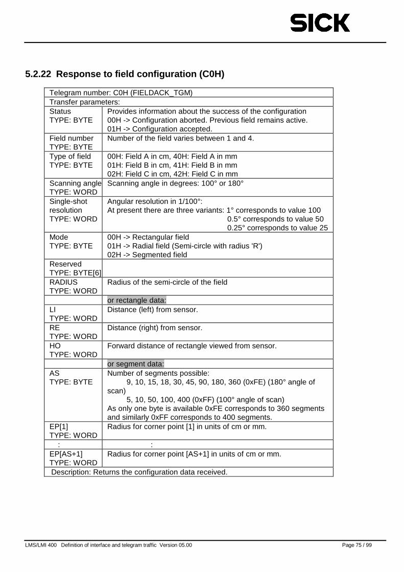
LMS/LMI 400 Definition of interface and telegram traffic Version 05.00 Page 75 / 99
5.2.22 Response to field configuration (C0H)
Telegram number: C0H (FIELDACK_TGM)Transfer parameters:StatusTYPE: BYTE
Provides information about the success of the configuration00H -> Configuration aborted. Previous field remains active.01H -> Configuration accepted.
Field numberTYPE: BYTE
Number of the field varies between 1 and 4.
Type of fieldTYPE: BYTE
00H: Field A in cm, 40H: Field A in mm01H: Field B in cm, 41H: Field B in mm02H: Field C in cm, 42H: Field C in mm
Scanning angleTYPE: WORD
Scanning angle in degrees: 100° or 180°
Single-shotresolutionTYPE: WORD
Angular resolution in 1/100°:At present there are three variants: 1° corresponds to value 100
0.5° corresponds to value 500.25° corresponds to value 25
ModeTYPE: BYTE
00H -> Rectangular field01H -> Radial field (Semi-circle with radius 'R')02H -> Segmented field
ReservedTYPE: BYTE[6]RADIUSTYPE: WORD
Radius of the semi-circle of the field
or rectangle data:LITYPE: WORD
Distance (left) from sensor.
RETYPE: WORD
Distance (right) from sensor.
HOTYPE: WORD
Forward distance of rectangle viewed from sensor.
or segment data:ASTYPE: BYTE
Number of segments possible:9, 10, 15, 18, 30, 45, 90, 180, 360 (0xFE) (180° angle of
scan)5, 10, 50, 100, 400 (0xFF) (100° angle of scan)
As only one byte is available 0xFE corresponds to 360 segmentsand similarly 0xFF corresponds to 400 segments.
EP[1]TYPE: WORD
Radius for corner point [1] in units of cm or mm.
: :EP[AS+1]TYPE: WORD
Radius for corner point [AS+1] in units of cm or mm.
Description: Returns the configuration data received.
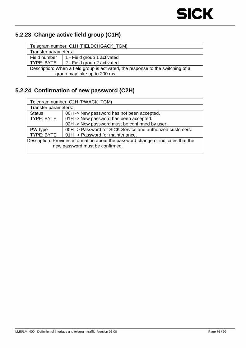
LMS/LMI 400 Definition of interface and telegram traffic Version 05.00 Page 76 / 99
5.2.23 Change active field group (C1H)
Telegram number: C1H (FIELDCHGACK_TGM)Transfer parameters:Field numberTYPE: BYTE
1 - Field group 1 activated2 - Field group 2 activated
Description: When a field group is activated, the response to the switching of agroup may take up to 200 ms.
5.2.24 Confirmation of new password (C2H)
Telegram number: C2H (PWACK_TGM)Transfer parameters:StatusTYPE: BYTE
00H -> New password has not been accepted.01H -> New password has been accepted.02H -> New password must be confirmed by user.
PW typeTYPE: BYTE
00H > Password for SICK Service and authorized customers.01H > Password for maintenance.
Description: Provides information about the password change or indicates that thenew password must be confirmed.
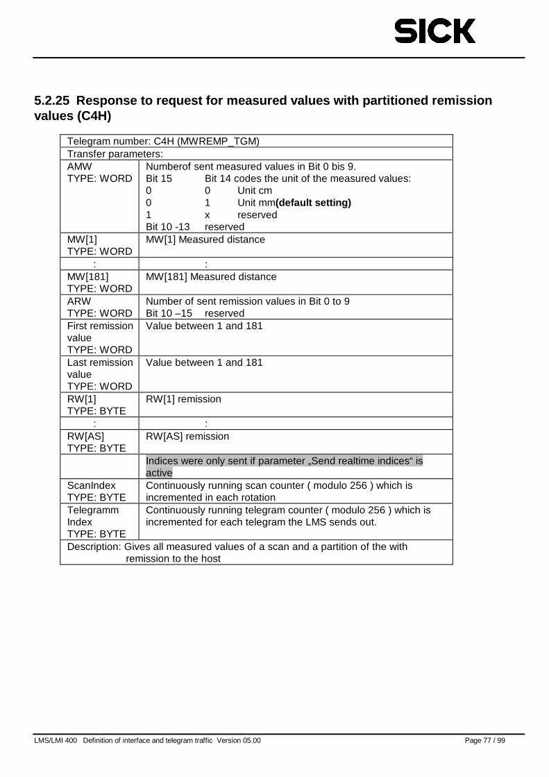
LMS/LMI 400 Definition of interface and telegram traffic Version 05.00 Page 77 / 99
5.2.25 Response to request for measured values with partitioned remissionvalues (C4H)
Telegram number: C4H (MWREMP_TGM)Transfer parameters:AMWTYPE: WORD
Numberof sent measured values in Bit 0 bis 9.Bit 15 Bit 14 codes the unit of the measured values:0 0 Unit cm0 1 Unit mm(default setting)1 x reservedBit 10 -13 reserved
MW[1]TYPE: WORD
MW[1] Measured distance
: :MW[181]TYPE: WORD
MW[181] Measured distance
ARWTYPE: WORD
Number of sent remission values in Bit 0 to 9Bit 10 –15 reserved
First remissionvalueTYPE: WORD
Value between 1 and 181
Last remissionvalueTYPE: WORD
Value between 1 and 181
RW[1]TYPE: BYTE
RW[1] remission
: :RW[AS]TYPE: BYTE
RW[AS] remission
Indices were only sent if parameter „Send realtime indices“ isactive
ScanIndexTYPE: BYTE
Continuously running scan counter ( modulo 256 ) which isincremented in each rotation
TelegrammIndexTYPE: BYTE
Continuously running telegram counter ( modulo 256 ) which isincremented for each telegram the LMS sends out.
Description: Gives all measured values of a scan and a partition of the withremission to the host
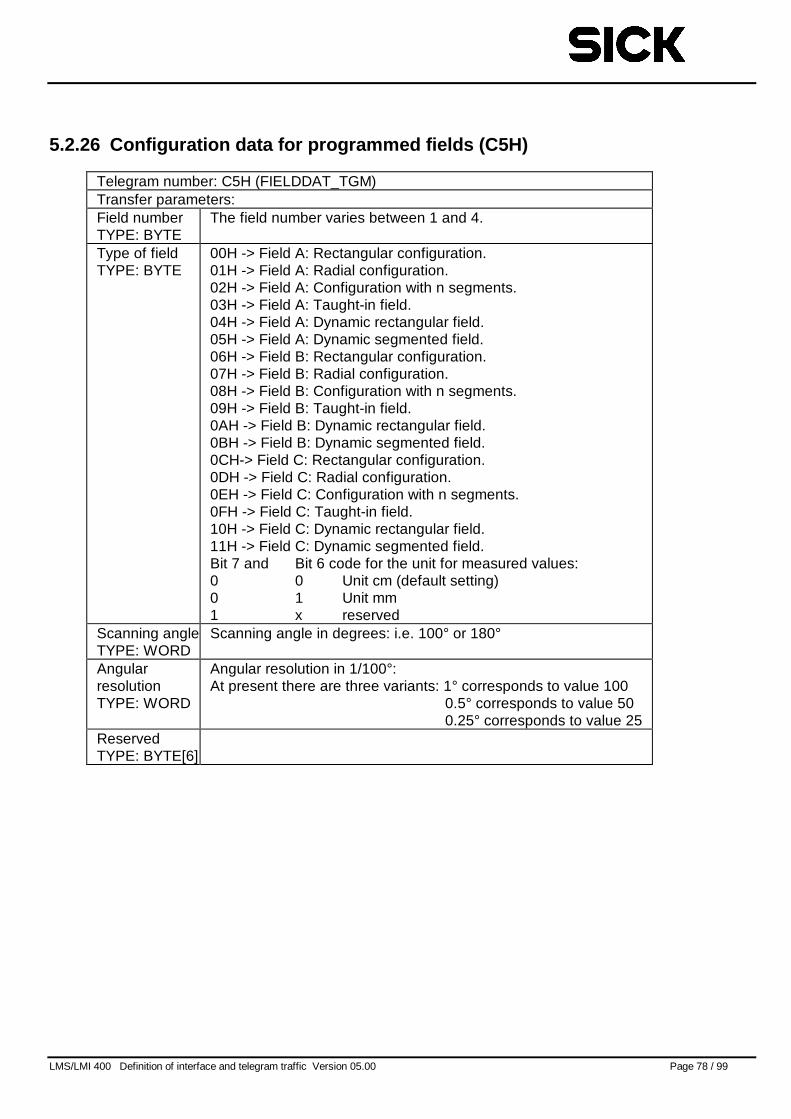
LMS/LMI 400 Definition of interface and telegram traffic Version 05.00 Page 78 / 99
5.2.26 Configuration data for programmed fields (C5H)
Telegram number: C5H (FIELDDAT_TGM)Transfer parameters:Field numberTYPE: BYTE
The field number varies between 1 and 4.
Type of fieldTYPE: BYTE
00H -> Field A: Rectangular configuration.01H -> Field A: Radial configuration.02H -> Field A: Configuration with n segments.03H -> Field A: Taught-in field.04H -> Field A: Dynamic rectangular field.05H -> Field A: Dynamic segmented field.06H -> Field B: Rectangular configuration.07H -> Field B: Radial configuration.08H -> Field B: Configuration with n segments.09H -> Field B: Taught-in field.0AH -> Field B: Dynamic rectangular field.0BH -> Field B: Dynamic segmented field.0CH-> Field C: Rectangular configuration.0DH -> Field C: Radial configuration.0EH -> Field C: Configuration with n segments.0FH -> Field C: Taught-in field.10H -> Field C: Dynamic rectangular field.11H -> Field C: Dynamic segmented field.Bit 7 and Bit 6 code for the unit for measured values:0 0 Unit cm (default setting)0 1 Unit mm1 x reserved
Scanning angleTYPE: WORD
Scanning angle in degrees: i.e. 100° or 180°
AngularresolutionTYPE: WORD
Angular resolution in 1/100°:At present there are three variants: 1° corresponds to value 100
0.5° corresponds to value 500.25° corresponds to value 25
ReservedTYPE: BYTE[6]
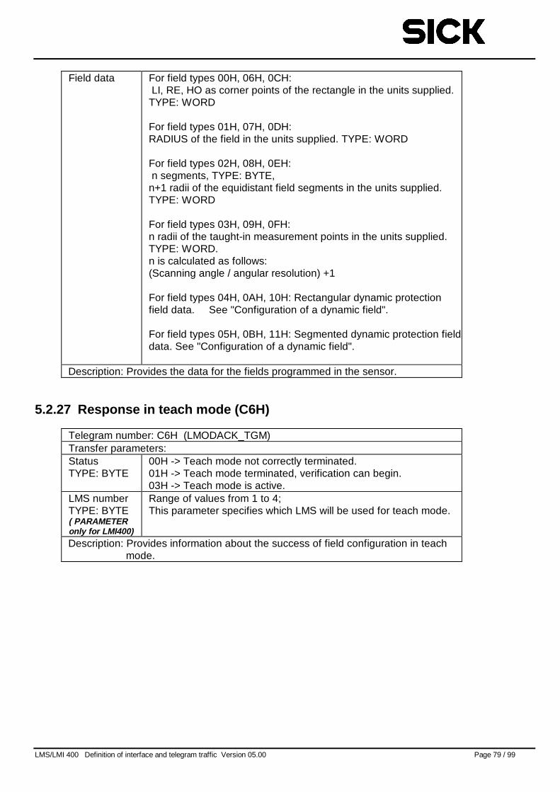
LMS/LMI 400 Definition of interface and telegram traffic Version 05.00 Page 79 / 99
Field data For field types 00H, 06H, 0CH:LI, RE, HO as corner points of the rectangle in the units supplied.
TYPE: WORD
For field types 01H, 07H, 0DH:RADIUS of the field in the units supplied. TYPE: WORD
For field types 02H, 08H, 0EH:n segments, TYPE: BYTE,
n+1 radii of the equidistant field segments in the units supplied.TYPE: WORD
For field types 03H, 09H, 0FH:n radii of the taught-in measurement points in the units supplied.TYPE: WORD.n is calculated as follows:(Scanning angle / angular resolution) +1
For field types 04H, 0AH, 10H: Rectangular dynamic protectionfield data. See "Configuration of a dynamic field".
For field types 05H, 0BH, 11H: Segmented dynamic protection fielddata. See "Configuration of a dynamic field".
Description: Provides the data for the fields programmed in the sensor.
5.2.27 Response in teach mode (C6H)
Telegram number: C6H (LMODACK_TGM)Transfer parameters:StatusTYPE: BYTE
00H -> Teach mode not correctly terminated.01H -> Teach mode terminated, verification can begin.03H -> Teach mode is active.
LMS numberTYPE: BYTE( PARAMETERonly for LMI400)
Range of values from 1 to 4;This parameter specifies which LMS will be used for teach mode.
Description: Provides information about the success of field configuration in teachmode.

LMS/LMI 400 Definition of interface and telegram traffic Version 05.00 Page 80 / 99
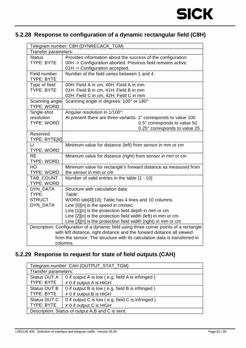
LMS/LMI 400 Definition of interface and telegram traffic Version 05.00 Page 81 / 99
5.2.28 Response to configuration of a dynamic rectangular field (C8H)
Telegram number: C8H (DYNRECACK_TGM)Transfer parameters:StatusTYPE: BYTE
Provides information about the success of the configuration00H -> Configuration aborted. Previous field remains active.01H -> Configuration accepted.
Field numberTYPE: BYTE
Number of the field varies between 1 and 4.
Type of fieldTYPE: BYTE
00H: Field A in cm, 40H: Field A in mm01H: Field B in cm, 41H: Field B in mm02H: Field C in cm, 42H: Field C in mm
Scanning angleTYPE: WORD
Scanning angle in degrees: 100° or 180°
Single-shotresolutionTYPE: WORD
Angular resolution in 1/100°:At present there are three variants: 1° corresponds to value 100
0.5° corresponds to value 500.25° corresponds to value 25
ReservedTYPE: BYTE[6]LITYPE: WORD
Minimum value for distance (left) from sensor in mm or cm
RETYPE: WORD
Minimum value for distance (right) from sensor in mm or cm
HOTYPE: WORD
Minimum value for rectangle's forward distance as measured fromthe sensor in mm or cm
TAB_COUNTTYPE: WORD
Number of valid entries in the table [1 - 10]
DYN_DATATYPE:STRUCTDYN_DATA
Structure with calculation data:Table:WORD tab[4][10]; Table has 4 lines and 10 columns.Line [0][n] is the speed in cm/secLine [1][n] is the protection field depth in mm or cmLine [2][n] is the protection field width (left) in mm or cmLine [3][n] is the protection field width (right) in mm or cm
Description: Configuration of a dynamic field using three corner points of a rectanglewith left distance, right distance and the forward distance all viewedfrom the sensor. The structure with its calculation data is transferred incolumns.
5.2.29 Response to request for state of field outputs (CAH)
Telegram number: CAH (OUTPUT_STAT_TGM)Transfer parameters:Status OUT ATYPE: BYTE
0 if output A is low ( e.g. field A is infringed )≠ 0 if output A is HIGH
Status OUT BTYPE: BYTE
0 if output B is low ( e.g. field B is infringed )≠ 0 if output B is HIGH
Status OUT CTYPE: BYTE
0 if output C is low ( e.g. field C is infringed )≠ 0 if output C is HIGH
Description: Status of output A,B and C is sent.
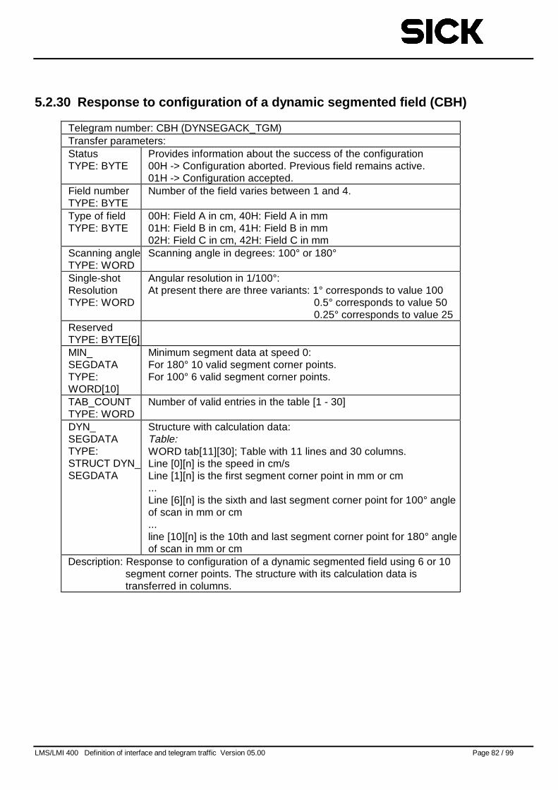
LMS/LMI 400 Definition of interface and telegram traffic Version 05.00 Page 82 / 99
5.2.30 Response to configuration of a dynamic segmented field (CBH)
Telegram number: CBH (DYNSEGACK_TGM)Transfer parameters:StatusTYPE: BYTE
Provides information about the success of the configuration00H -> Configuration aborted. Previous field remains active.01H -> Configuration accepted.
Field numberTYPE: BYTE
Number of the field varies between 1 and 4.
Type of fieldTYPE: BYTE
00H: Field A in cm, 40H: Field A in mm01H: Field B in cm, 41H: Field B in mm02H: Field C in cm, 42H: Field C in mm
Scanning angleTYPE: WORD
Scanning angle in degrees: 100° or 180°
Single-shotResolutionTYPE: WORD
Angular resolution in 1/100°:At present there are three variants: 1° corresponds to value 100
0.5° corresponds to value 500.25° corresponds to value 25
ReservedTYPE: BYTE[6]MIN_SEGDATATYPE:WORD[10]
Minimum segment data at speed 0:For 180° 10 valid segment corner points.For 100° 6 valid segment corner points.
TAB_COUNTTYPE: WORD
Number of valid entries in the table [1 - 30]
DYN_SEGDATATYPE:STRUCT DYN_SEGDATA
Structure with calculation data:Table:WORD tab[11][30]; Table with 11 lines and 30 columns.Line [0][n] is the speed in cm/sLine [1][n] is the first segment corner point in mm or cm...Line [6][n] is the sixth and last segment corner point for 100° angleof scan in mm or cm...line [10][n] is the 10th and last segment corner point for 180° angleof scan in mm or cm
Description: Response to configuration of a dynamic segmented field using 6 or 10segment corner points. The structure with its calculation data istransferred in columns.
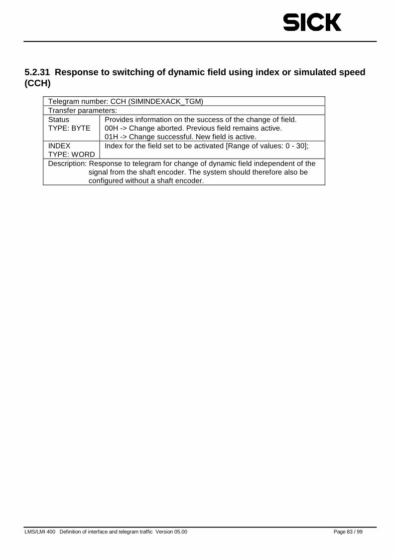
LMS/LMI 400 Definition of interface and telegram traffic Version 05.00 Page 83 / 99
5.2.31 Response to switching of dynamic field using index or simulated speed(CCH)
Telegram number: CCH (SIMINDEXACK_TGM)Transfer parameters:StatusTYPE: BYTE
Provides information on the success of the change of field.00H -> Change aborted. Previous field remains active.01H -> Change successful. New field is active.
INDEXTYPE: WORD
Index for the field set to be activated [Range of values: 0 - 30];
Description: Response to telegram for change of dynamic field independent of thesignal from the shaft encoder. The system should therefore also beconfigured without a shaft encoder.
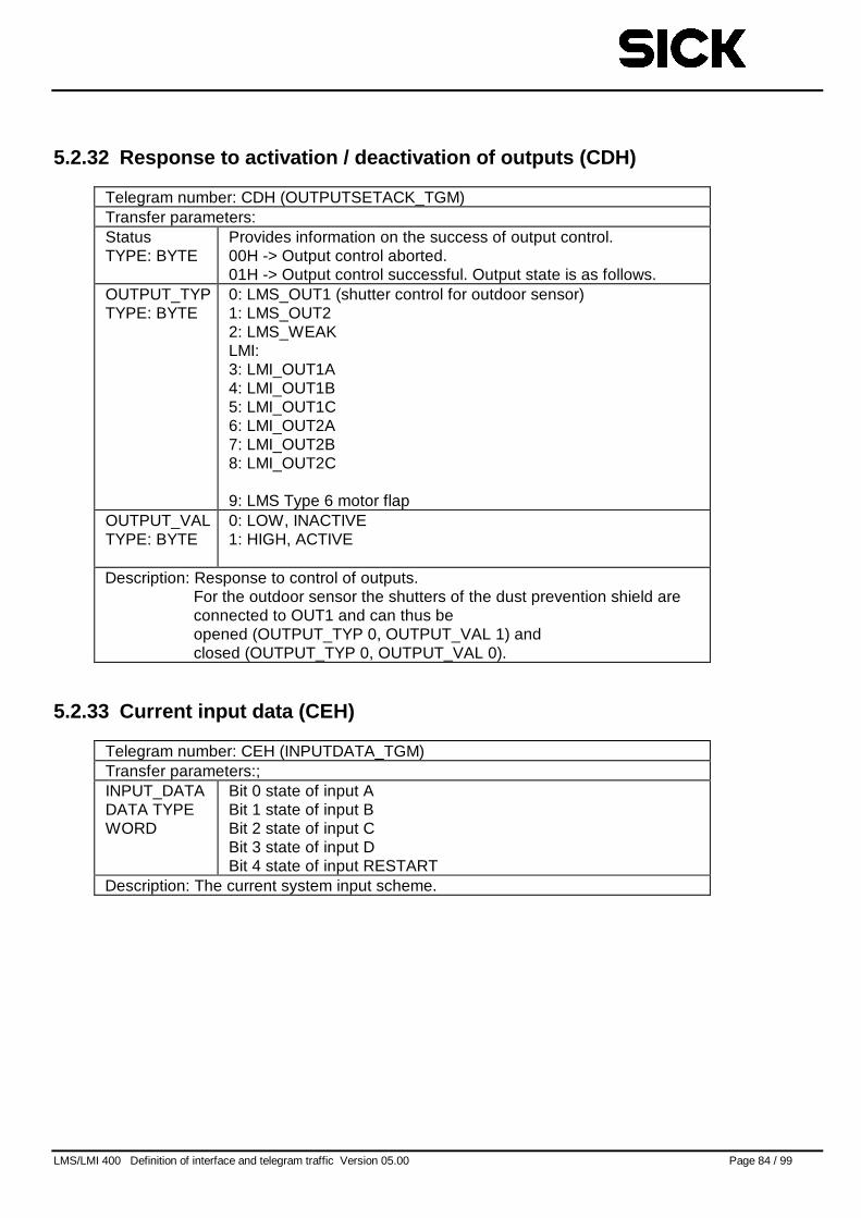
LMS/LMI 400 Definition of interface and telegram traffic Version 05.00 Page 84 / 99
5.2.32 Response to activation / deactivation of outputs (CDH)
Telegram number: CDH (OUTPUTSETACK_TGM)Transfer parameters:StatusTYPE: BYTE
Provides information on the success of output control.00H -> Output control aborted.01H -> Output control successful. Output state is as follows.
OUTPUT_TYPTYPE: BYTE
0: LMS_OUT1 (shutter control for outdoor sensor)1: LMS_OUT22: LMS_WEAKLMI:3: LMI_OUT1A4: LMI_OUT1B5: LMI_OUT1C6: LMI_OUT2A7: LMI_OUT2B8: LMI_OUT2C
9: LMS Type 6 motor flapOUTPUT_VALTYPE: BYTE
0: LOW, INACTIVE1: HIGH, ACTIVE
Description: Response to control of outputs.For the outdoor sensor the shutters of the dust prevention shield areconnected to OUT1 and can thus beopened (OUTPUT_TYP 0, OUTPUT_VAL 1) andclosed (OUTPUT_TYP 0, OUTPUT_VAL 0).
5.2.33 Current input data (CEH)
Telegram number: CEH (INPUTDATA_TGM)Transfer parameters:;INPUT_DATADATA TYPEWORD
Bit 0 state of input ABit 1 state of input BBit 2 state of input CBit 3 state of input DBit 4 state of input RESTART
Description: The current system input scheme.
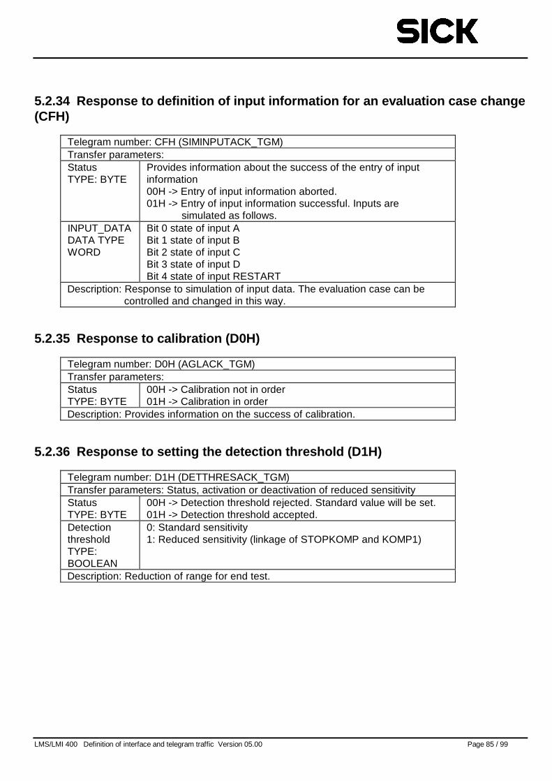
LMS/LMI 400 Definition of interface and telegram traffic Version 05.00 Page 85 / 99
5.2.34 Response to definition of input information for an evaluation case change(CFH)
Telegram number: CFH (SIMINPUTACK_TGM)Transfer parameters:StatusTYPE: BYTE
Provides information about the success of the entry of inputinformation00H -> Entry of input information aborted.01H -> Entry of input information successful. Inputs are
simulated as follows.INPUT_DATADATA TYPEWORD
Bit 0 state of input ABit 1 state of input BBit 2 state of input CBit 3 state of input DBit 4 state of input RESTART
Description: Response to simulation of input data. The evaluation case can becontrolled and changed in this way.
5.2.35 Response to calibration (D0H)
Telegram number: D0H (AGLACK_TGM)Transfer parameters:StatusTYPE: BYTE
00H -> Calibration not in order01H -> Calibration in order
Description: Provides information on the success of calibration.
5.2.36 Response to setting the detection threshold (D1H)
Telegram number: D1H (DETTHRESACK_TGM)Transfer parameters: Status, activation or deactivation of reduced sensitivityStatusTYPE: BYTE
00H -> Detection threshold rejected. Standard value will be set.01H -> Detection threshold accepted.
DetectionthresholdTYPE:BOOLEAN
0: Standard sensitivity1: Reduced sensitivity (linkage of STOPKOMP and KOMP1)
Description: Reduction of range for end test.
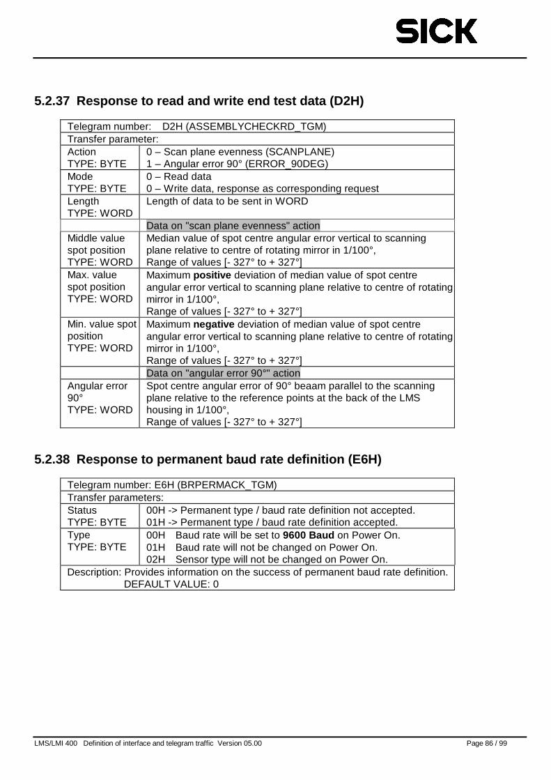
LMS/LMI 400 Definition of interface and telegram traffic Version 05.00 Page 86 / 99
5.2.37 Response to read and write end test data (D2H)
Telegram number: D2H (ASSEMBLYCHECKRD_TGM)Transfer parameter:ActionTYPE: BYTE
0 – Scan plane evenness (SCANPLANE)1 – Angular error 90° (ERROR_90DEG)
ModeTYPE: BYTE
0 – Read data0 – Write data, response as corresponding request
LengthTYPE: WORD
Length of data to be sent in WORD
Data on "scan plane evenness" actionMiddle valuespot positionTYPE: WORD
Median value of spot centre angular error vertical to scanningplane relative to centre of rotating mirror in 1/100°,Range of values [- 327° to + 327°]
Max. valuespot positionTYPE: WORD
Maximum positive deviation of median value of spot centreangular error vertical to scanning plane relative to centre of rotatingmirror in 1/100°,Range of values [- 327° to + 327°]
Min. value spotpositionTYPE: WORD
Maximum negative deviation of median value of spot centreangular error vertical to scanning plane relative to centre of rotatingmirror in 1/100°,Range of values [- 327° to + 327°]Data on "angular error 90°" action
Angular error90°TYPE: WORD
Spot centre angular error of 90° beaam parallel to the scanningplane relative to the reference points at the back of the LMShousing in 1/100°,Range of values [- 327° to + 327°]
5.2.38 Response to permanent baud rate definition (E6H)
Telegram number: E6H (BRPERMACK_TGM)Transfer parameters:StatusTYPE: BYTE
00H -> Permanent type / baud rate definition not accepted.01H -> Permanent type / baud rate definition accepted.
TypeTYPE: BYTE
00H Baud rate will be set to 9600 Baud on Power On.01H Baud rate will not be changed on Power On.02H Sensor type will not be changed on Power On.
Description: Provides information on the success of permanent baud rate definition.DEFAULT VALUE: 0
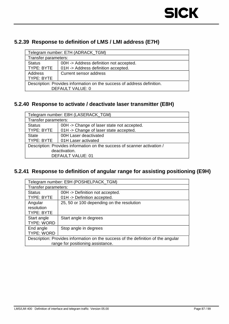
LMS/LMI 400 Definition of interface and telegram traffic Version 05.00 Page 87 / 99
5.2.39 Response to definition of LMS / LMI address (E7H)
Telegram number: E7H (ADRACK_TGM)Transfer parameters:StatusTYPE: BYTE
00H -> Address definition not accepted.01H -> Address definition accepted.
AddressTYPE: BYTE
Current sensor address
Description: Provides information on the success of address definition.DEFAULT VALUE: 0
5.2.40 Response to activate / deactivate laser transmitter (E8H)
Telegram number: E8H (LASERACK_TGM)Transfer parameters:StatusTYPE: BYTE
00H -> Change of laser state not accepted.01H -> Change of laser state accepted.
StateTYPE: BYTE
00H Laser deactivated01H Laser activated
Description: Provides information on the success of scanner activation /deactivation.DEFAULT VALUE: 01
5.2.41 Response to definition of angular range for assisting positioning (E9H)
Telegram number: E9H (POSHELPACK_TGM)Transfer parameters:StatusTYPE: BYTE
00H -> Definition not accepted.01H -> Definition accepted.
AngularresolutionTYPE: BYTE
25, 50 or 100 depending on the resolution
Start angleTYPE: WORD
Start angle in degrees
End angleTYPE: WORD
Stop angle in degrees
Description: Provides information on the success of the definition of the angularrange for positioning assistance.
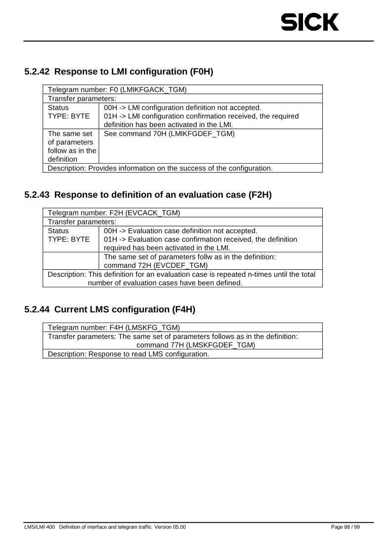
LMS/LMI 400 Definition of interface and telegram traffic Version 05.00 Page 88 / 99
5.2.42 Response to LMI configuration (F0H)
Telegram number: F0 (LMIKFGACK_TGM)Transfer parameters:StatusTYPE: BYTE
00H -> LMI configuration definition not accepted.01H -> LMI configuration confirmation received, the requireddefinition has been activated in the LMI.
The same setof parametersfollow as in thedefinition
See command 70H (LMIKFGDEF_TGM)
Description: Provides information on the success of the configuration.
5.2.43 Response to definition of an evaluation case (F2H)
Telegram number: F2H (EVCACK_TGM)Transfer parameters:StatusTYPE: BYTE
00H -> Evaluation case definition not accepted.01H -> Evaluation case confirmation received, the definitionrequired has been activated in the LMI.The same set of parameters follw as in the definition:command 72H (EVCDEF_TGM)
Description: This definition for an evaluation case is repeated n-times until the totalnumber of evaluation cases have been defined.
5.2.44 Current LMS configuration (F4H)
Telegram number: F4H (LMSKFG_TGM)Transfer parameters: The same set of parameters follows as in the definition:
command 77H (LMSKFGDEF_TGM)Description: Response to read LMS configuration.
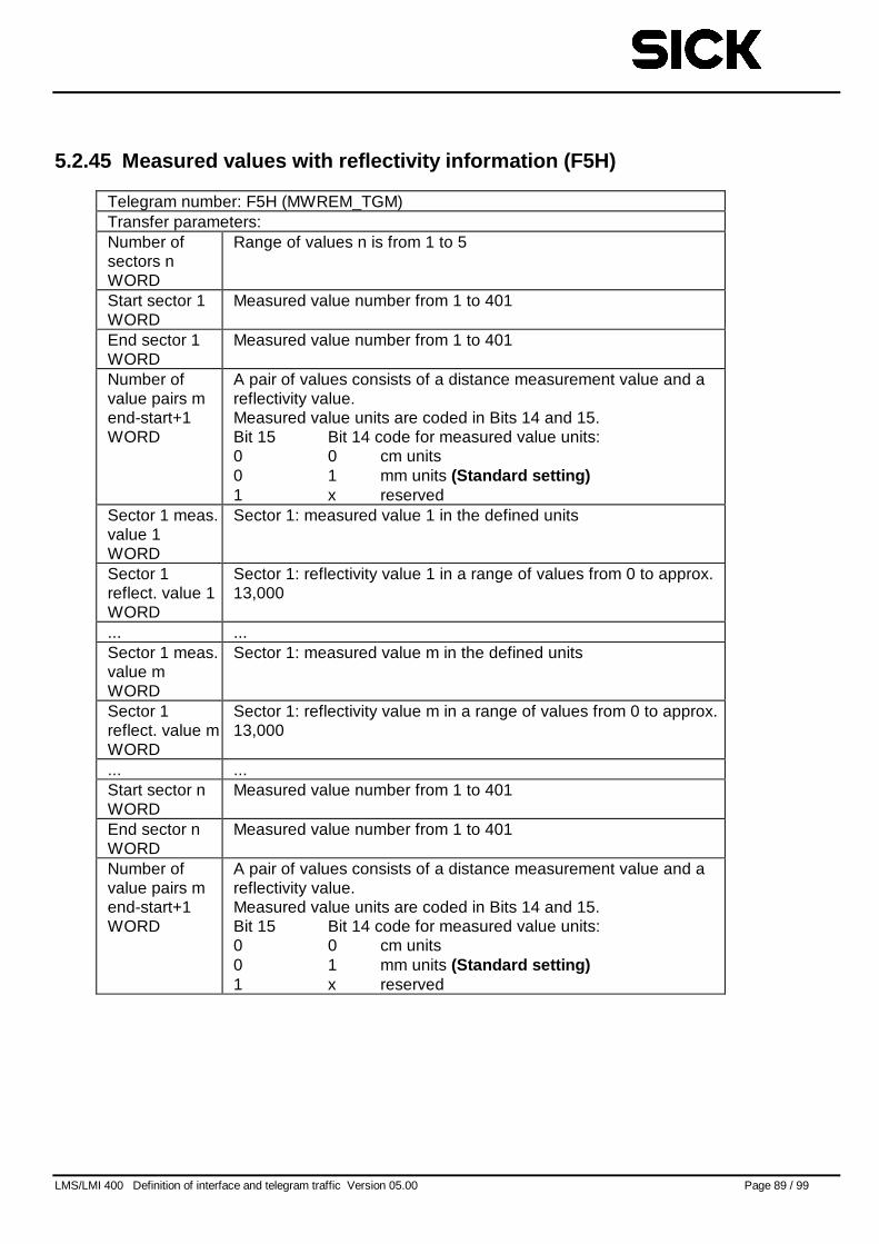
LMS/LMI 400 Definition of interface and telegram traffic Version 05.00 Page 89 / 99
5.2.45 Measured values with reflectivity information (F5H)
Telegram number: F5H (MWREM_TGM)Transfer parameters:Number ofsectors nWORD
Range of values n is from 1 to 5
Start sector 1WORD
Measured value number from 1 to 401
End sector 1WORD
Measured value number from 1 to 401
Number ofvalue pairs mend-start+1WORD
A pair of values consists of a distance measurement value and areflectivity value.Measured value units are coded in Bits 14 and 15.Bit 15 Bit 14 code for measured value units:0 0 cm units0 1 mm units (Standard setting)1 x reserved
Sector 1 meas.value 1WORD
Sector 1: measured value 1 in the defined units
Sector 1reflect. value 1WORD
Sector 1: reflectivity value 1 in a range of values from 0 to approx.13,000
... ...Sector 1 meas.value mWORD
Sector 1: measured value m in the defined units
Sector 1reflect. value mWORD
Sector 1: reflectivity value m in a range of values from 0 to approx.13,000
... ...Start sector nWORD
Measured value number from 1 to 401
End sector nWORD
Measured value number from 1 to 401
Number ofvalue pairs mend-start+1WORD
A pair of values consists of a distance measurement value and areflectivity value.Measured value units are coded in Bits 14 and 15.Bit 15 Bit 14 code for measured value units:0 0 cm units0 1 mm units (Standard setting)1 x reserved
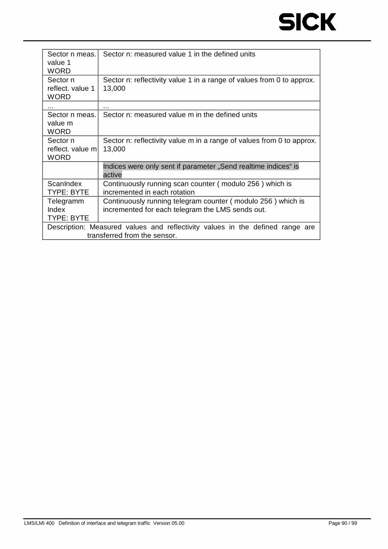
LMS/LMI 400 Definition of interface and telegram traffic Version 05.00 Page 90 / 99
Sector n meas.value 1WORD
Sector n: measured value 1 in the defined units
Sector nreflect. value 1WORD
Sector n: reflectivity value 1 in a range of values from 0 to approx.13,000
... ...Sector n meas.value mWORD
Sector n: measured value m in the defined units
Sector nreflect. value mWORD
Sector n: reflectivity value m in a range of values from 0 to approx.13,000
Indices were only sent if parameter „Send realtime indices“ isactive
ScanIndexTYPE: BYTE
Continuously running scan counter ( modulo 256 ) which isincremented in each rotation
TelegrammIndexTYPE: BYTE
Continuously running telegram counter ( modulo 256 ) which isincremented for each telegram the LMS sends out.
Description: Measured values and reflectivity values in the defined range aretransferred from the sensor.
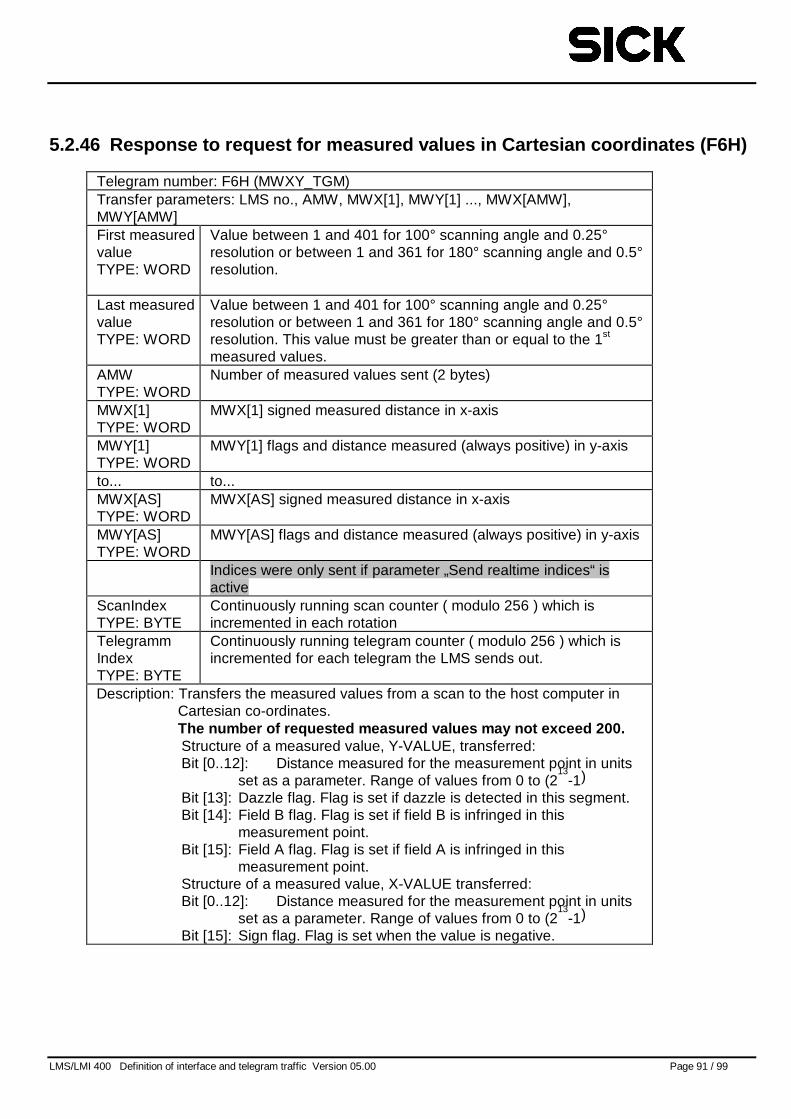
LMS/LMI 400 Definition of interface and telegram traffic Version 05.00 Page 91 / 99
5.2.46 Response to request for measured values in Cartesian coordinates (F6H)
Telegram number: F6H (MWXY_TGM)Transfer parameters: LMS no., AMW, MWX[1], MWY[1] ..., MWX[AMW],MWY[AMW]First measuredvalueTYPE: WORD
Value between 1 and 401 for 100° scanning angle and 0.25°resolution or between 1 and 361 for 180° scanning angle and 0.5°resolution.
Last measuredvalueTYPE: WORD
Value between 1 and 401 for 100° scanning angle and 0.25°resolution or between 1 and 361 for 180° scanning angle and 0.5°resolution. This value must be greater than or equal to the 1st
measured values.AMWTYPE: WORD
Number of measured values sent (2 bytes)
MWX[1]TYPE: WORD
MWX[1] signed measured distance in x-axis
MWY[1]TYPE: WORD
MWY[1] flags and distance measured (always positive) in y-axis
to... to...MWX[AS]TYPE: WORD
MWX[AS] signed measured distance in x-axis
MWY[AS]TYPE: WORD
MWY[AS] flags and distance measured (always positive) in y-axis
Indices were only sent if parameter „Send realtime indices“ isactive
ScanIndexTYPE: BYTE
Continuously running scan counter ( modulo 256 ) which isincremented in each rotation
TelegrammIndexTYPE: BYTE
Continuously running telegram counter ( modulo 256 ) which isincremented for each telegram the LMS sends out.
Description: Transfers the measured values from a scan to the host computer inCartesian co-ordinates.The number of requested measured values may not exceed 200.Structure of a measured value, Y-VALUE, transferred:Bit [0..12]: Distance measured for the measurement point in units
set as a parameter. Range of values from 0 to (213
-1)
Bit [13]: Dazzle flag. Flag is set if dazzle is detected in this segment.Bit [14]: Field B flag. Flag is set if field B is infringed in this
measurement point.Bit [15]: Field A flag. Flag is set if field A is infringed in this
measurement point.Structure of a measured value, X-VALUE transferred:Bit [0..12]: Distance measured for the measurement point in units
set as a parameter. Range of values from 0 to (213
-1)
Bit [15]: Sign flag. Flag is set when the value is negative.
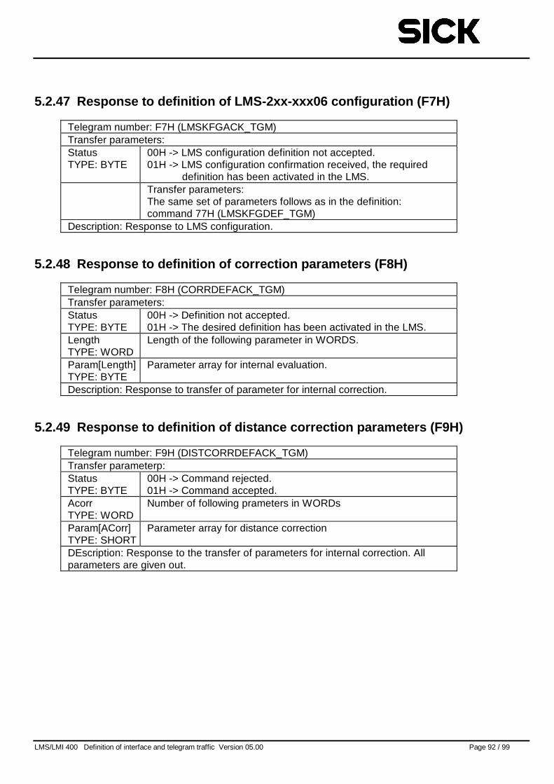
LMS/LMI 400 Definition of interface and telegram traffic Version 05.00 Page 92 / 99
5.2.47 Response to definition of LMS-2xx-xxx06 configuration (F7H)
Telegram number: F7H (LMSKFGACK_TGM)Transfer parameters:StatusTYPE: BYTE
00H -> LMS configuration definition not accepted.01H -> LMS configuration confirmation received, the required
definition has been activated in the LMS.Transfer parameters:The same set of parameters follows as in the definition:command 77H (LMSKFGDEF_TGM)
Description: Response to LMS configuration.
5.2.48 Response to definition of correction parameters (F8H)
Telegram number: F8H (CORRDEFACK_TGM)Transfer parameters:StatusTYPE: BYTE
00H -> Definition not accepted.01H -> The desired definition has been activated in the LMS.
LengthTYPE: WORD
Length of the following parameter in WORDS.
Param[Length]TYPE: BYTE
Parameter array for internal evaluation.
Description: Response to transfer of parameter for internal correction.
5.2.49 Response to definition of distance correction parameters (F9H)
Telegram number: F9H (DISTCORRDEFACK_TGM)Transfer parameterp:StatusTYPE: BYTE
00H -> Command rejected.01H -> Command accepted.
AcorrTYPE: WORD
Number of following prameters in WORDs
Param[ACorr]TYPE: SHORT
Parameter array for distance correction
DEscription: Response to the transfer of parameters for internal correction. Allparameters are given out.
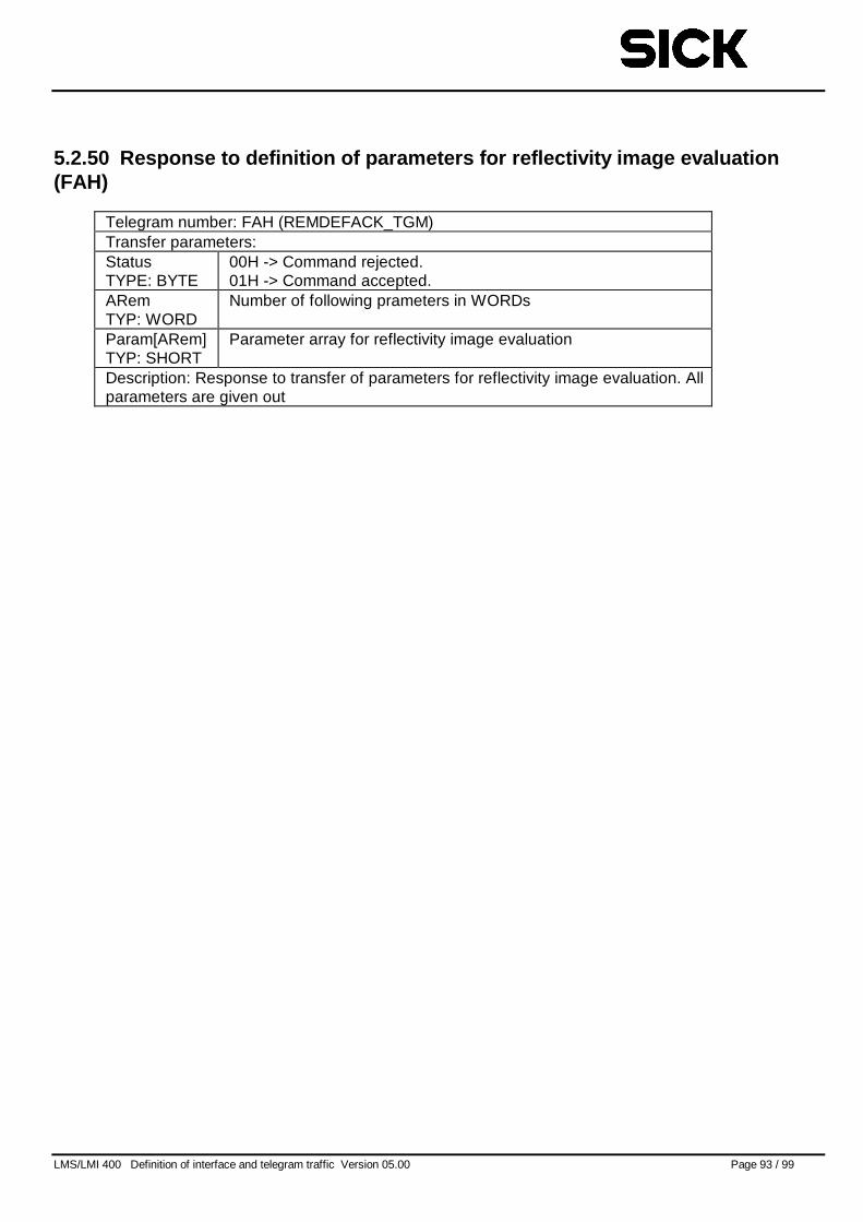
LMS/LMI 400 Definition of interface and telegram traffic Version 05.00 Page 93 / 99
5.2.50 Response to definition of parameters for reflectivity image evaluation(FAH)
Telegram number: FAH (REMDEFACK_TGM)Transfer parameters:StatusTYPE: BYTE
00H -> Command rejected.01H -> Command accepted.
ARemTYP: WORD
Number of following prameters in WORDs
Param[ARem]TYP: SHORT
Parameter array for reflectivity image evaluation
Description: Response to transfer of parameters for reflectivity image evaluation. Allparameters are given out
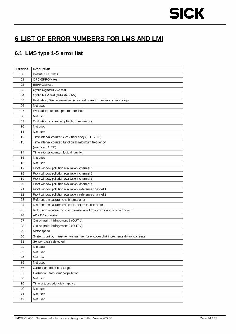
LMS/LMI 400 Definition of interface and telegram traffic Version 05.00 Page 94 / 99
6 LIST OF ERROR NUMBERS FOR LMS AND LMI
6.1 LMS type 1-5 error list
Error no. Description
00 Internal CPU tests
01 CRC-EPROM test
02 EEPROM test
03 Cyclic register/RAM test
04 Cyclic RAM test (fail-safe RAM)
05 Evaluation; Dazzle evaluation (constant current, comparator, monoflop)
06 Not used
07 Evaluation; stop comparator threshold
08 Not used
09 Evaluation of signal amplitude; comparators
10 Not used
11 Not used
12 Time interval counter; clock frequency (PLL, VCO)
13 Time interval counter; function at maximum frequency
(overflow ±1LSB)
14 Time interval counter; logical function
15 Not used
16 Not used
17 Front window pollution evaluation; channel 1
18 Front window pollution evaluation; channel 2
19 Front window pollution evaluation; channel 3
20 Front window pollution evaluation; channel 4
21 Front window pollution evaluation; reference channel 1
22 Front window pollution evaluation; reference channel 2
23 Reference measurement; internal error
24 Reference measurement; offset determination of TIC
25 Reference measurement; determination of transmitter and receiver power
26 AD / DA converter
27 Cut-off path; infringement 1 (OUT 1)
28 Cut-off path; infringement 2 (OUT 2)
29 Motor speed
30 System control; measurement number for encoder disk increments do not correlate
31 Sensor dazzle detected
32 Not used
33 Not used
34 Not used
35 Not used
36 Calibration; reference target
37 Calibration; front window pollution
38 Not used
39 Time out; encoder disk impulse
40 Not used
41 Not used
42 Not used
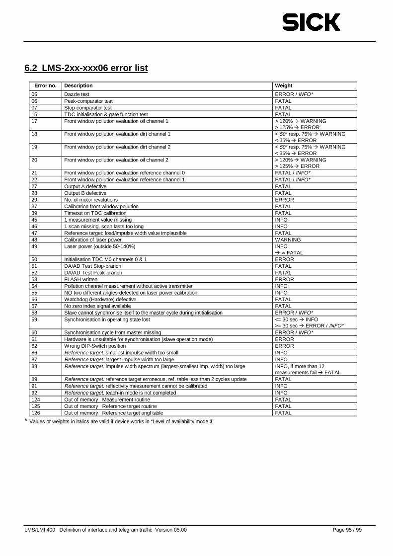
LMS/LMI 400 Definition of interface and telegram traffic Version 05.00 Page 95 / 99
6.2 LMS-2xx-xxx06 error list
Error no. Description Weight
05 Dazzle test ERROR / INFO*06 Peak-comparator test FATAL07 Stop-comparator test FATAL15 TDC initialisation & gate function test FATAL17 Front window pollution evaluation oil channel 1 > 120% � WARNING
> 125% � ERROR18 Front window pollution evaluation dirt channel 1 < 50* resp. 75% � WARNING
< 35% � ERROR19 Front window pollution evaluation dirt channel 2 < 50* resp. 75% � WARNING
< 35% � ERROR20 Front window pollution evaluation oil channel 2 > 120% � WARNING
> 125% � ERROR21 Front window pollution evaluation reference channel 0 FATAL / INFO*22 Front window pollution evaluation reference channel 1 FATAL / INFO*27 Output A defective FATAL28 Output B defective FATAL29 No. of motor revolutions ERROR37 Calibration front window pollution FATAL39 Timeout on TDC calibration FATAL45 1 measurement value missing INFO46 1 scan missing, scan lasts too long INFO47 Reference target: load/impulse width value implausible FATAL48 Calibration of laser power WARNING49 Laser power (outside 50-140%) INFO
� ∞ FATAL50 Initialisation TDC M0 channels 0 & 1 ERROR51 DA/AD Test Stop-branch FATAL52 DA/AD Test Peak-branch FATAL53 FLASH written ERROR54 Pollution channel measurement without active transmitter INFO55 NO two different angles detected on laser power calibration INFO56 Watchdog (Hardware) defective FATAL57 No zero index signal available FATAL58 Slave cannot synchronise itself to the master cycle during intitialisation ERROR / INFO*59 Synchronisation in operating state lost <= 30 sec � INFO
>= 30 sec � ERROR / INFO*60 Synchronisation cycle from master missing ERROR / INFO*61 Hardware is unsuitable for synchronisation (slave operation mode) ERROR62 Wrong DIP-Switch position ERROR86 Reference target: smallest impulse width too small INFO87 Reference target: largest impulse width too large INFO88 Reference target: impulse width spectrum (largest-smallest imp. width) too large INFO, if more than 12
measurements fail � FATAL89 Reference target: reference target erroneous, ref. table less than 2 cycles update FATAL91 Reference target: reflectivity measurement cannot be calibrated INFO92 Reference target: teach-in mode is not completed INFO124 Out of memory Measurement routine FATAL125 Out of memory Reference target routine FATAL126 Out of memory Reference target angl table FATAL
* Values or weights in italics are valid if device works in “Level of availability mode 3”
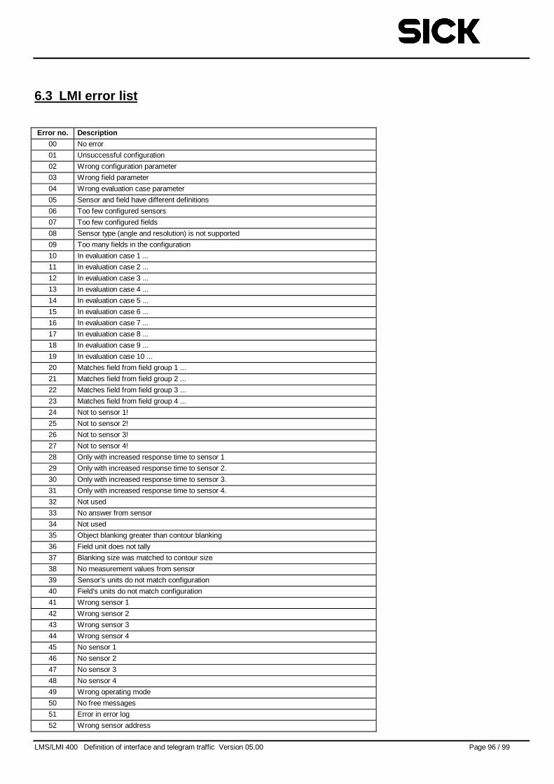
LMS/LMI 400 Definition of interface and telegram traffic Version 05.00 Page 96 / 99
6.3 LMI error list
Error no. Description
00 No error
01 Unsuccessful configuration
02 Wrong configuration parameter
03 Wrong field parameter
04 Wrong evaluation case parameter
05 Sensor and field have different definitions
06 Too few configured sensors
07 Too few configured fields
08 Sensor type (angle and resolution) is not supported
09 Too many fields in the configuration
10 In evaluation case 1 ...
11 In evaluation case 2 ...
12 In evaluation case 3 ...
13 In evaluation case 4 ...
14 In evaluation case 5 ...
15 In evaluation case 6 ...
16 In evaluation case 7 ...
17 In evaluation case 8 ...
18 In evaluation case 9 ...
19 In evaluation case 10 ...
20 Matches field from field group 1 ...
21 Matches field from field group 2 ...
22 Matches field from field group 3 ...
23 Matches field from field group 4 ...
24 Not to sensor 1!
25 Not to sensor 2!
26 Not to sensor 3!
27 Not to sensor 4!
28 Only with increased response time to sensor 1
29 Only with increased response time to sensor 2.
30 Only with increased response time to sensor 3.
31 Only with increased response time to sensor 4.
32 Not used
33 No answer from sensor
34 Not used
35 Object blanking greater than contour blanking
36 Field unit does not tally
37 Blanking size was matched to contour size
38 No measurement values from sensor
39 Sensor's units do not match configuration
40 Field's units do not match configuration
41 Wrong sensor 1
42 Wrong sensor 2
43 Wrong sensor 3
44 Wrong sensor 4
45 No sensor 1
46 No sensor 2
47 No sensor 3
48 No sensor 4
49 Wrong operating mode
50 No free messages
51 Error in error log
52 Wrong sensor address
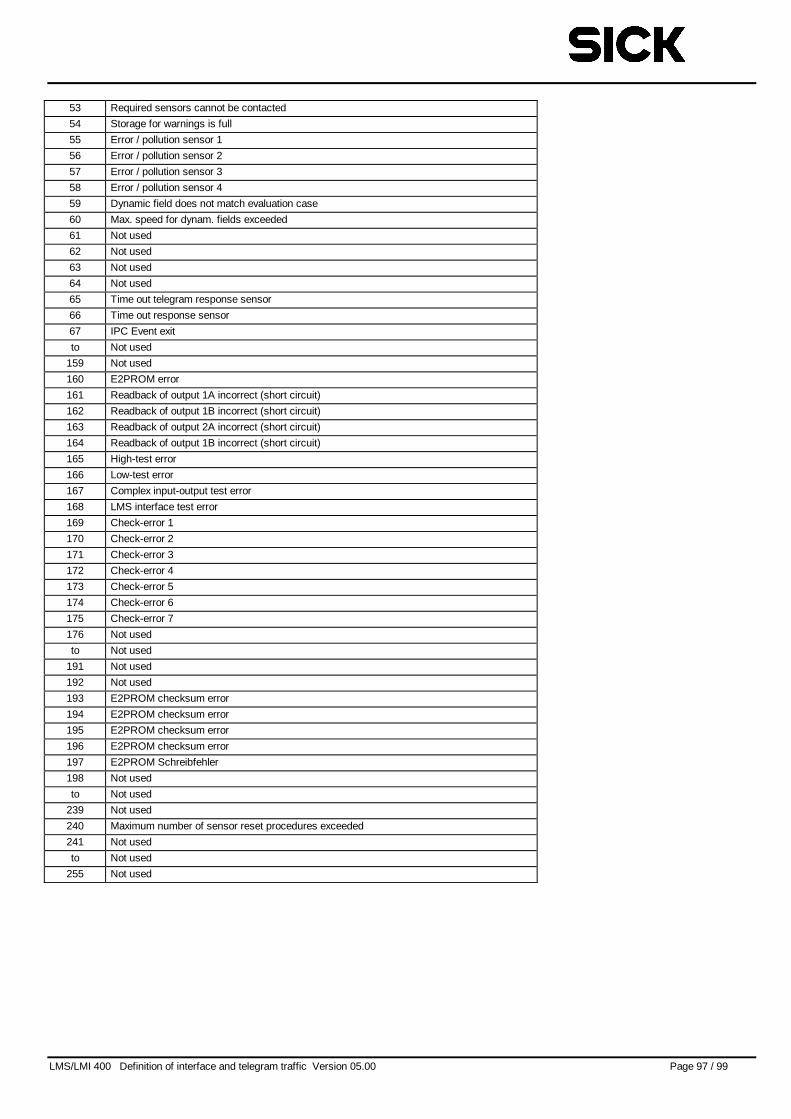
LMS/LMI 400 Definition of interface and telegram traffic Version 05.00 Page 97 / 99
53 Required sensors cannot be contacted
54 Storage for warnings is full
55 Error / pollution sensor 1
56 Error / pollution sensor 2
57 Error / pollution sensor 3
58 Error / pollution sensor 4
59 Dynamic field does not match evaluation case
60 Max. speed for dynam. fields exceeded
61 Not used
62 Not used
63 Not used
64 Not used
65 Time out telegram response sensor
66 Time out response sensor
67 IPC Event exit
to Not used
159 Not used
160 E2PROM error
161 Readback of output 1A incorrect (short circuit)
162 Readback of output 1B incorrect (short circuit)
163 Readback of output 2A incorrect (short circuit)
164 Readback of output 1B incorrect (short circuit)
165 High-test error
166 Low-test error
167 Complex input-output test error
168 LMS interface test error
169 Check-error 1
170 Check-error 2
171 Check-error 3
172 Check-error 4
173 Check-error 5
174 Check-error 6
175 Check-error 7
176 Not used
to Not used
191 Not used
192 Not used
193 E2PROM checksum error
194 E2PROM checksum error
195 E2PROM checksum error
196 E2PROM checksum error
197 E2PROM Schreibfehler
198 Not used
to Not used
239 Not used
240 Maximum number of sensor reset procedures exceeded
241 Not used
to Not used
255 Not used
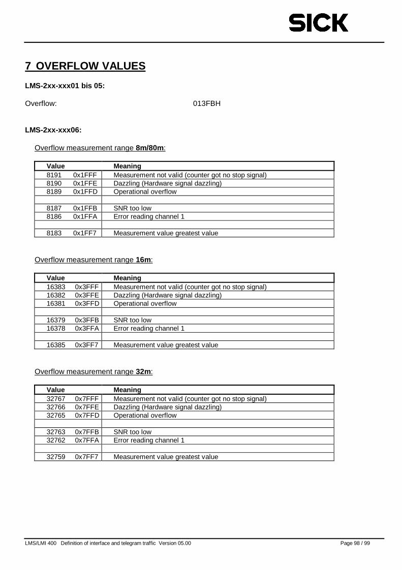
LMS/LMI 400 Definition of interface and telegram traffic Version 05.00 Page 98 / 99
7 OVERFLOW VALUES
LMS-2xx-xxx01 bis 05:
Overflow: 013FBH
LMS-2xx-xxx06:
Overflow measurement range 8m/80m :
Value Meaning8191 0x1FFF Measurement not valid (counter got no stop signal)8190 0x1FFE Dazzling (Hardware signal dazzling)8189 0x1FFD Operational overflow
8187 0x1FFB SNR too low8186 0x1FFA Error reading channel 1
8183 0x1FF7 Measurement value greatest value
Overflow measurement range 16m:
Value Meaning16383 0x3FFF Measurement not valid (counter got no stop signal)16382 0x3FFE Dazzling (Hardware signal dazzling)16381 0x3FFD Operational overflow
16379 0x3FFB SNR too low16378 0x3FFA Error reading channel 1
16385 0x3FF7 Measurement value greatest value
Overflow measurement range 32m:
Value Meaning32767 0x7FFF Measurement not valid (counter got no stop signal)32766 0x7FFE Dazzling (Hardware signal dazzling)32765 0x7FFD Operational overflow
32763 0x7FFB SNR too low32762 0x7FFA Error reading channel 1
32759 0x7FF7 Measurement value greatest value
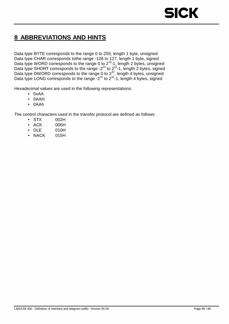
LMS/LMI 400 Definition of interface and telegram traffic Version 05.00 Page 99 / 99
8 ABBREVIATIONS AND HINTS
Data type BYTE corresponds to the range 0 to 255, length 1 byte, unsignedData type CHAR corresponds tothe range -128 to 127, length 1 byte, signedData type WORD corresponds to the range 0 to 216-1, length 2 bytes, unsignedData type SHORT corresponds to the range -215 to 215-1, length 2 bytes, signedData type DWORD corresponds to the range 0 to 232, length 4 bytes, unsignedData type LONG corresponds to the range -231 to 231-1, length 4 bytes, signed
Hexadecimal values are used in the following representations:• 0xAA• 0AAH• 0AAh
The control characters used in the transfer protocol are defined as follows:• STX 002H• ACK 006H• DLE 010H• NACK 015H


![~V4 ffi~~~~~@ti~T~ ~~~~~(g~ ©©lMi]lMi]~[M[Q) …](https://img.pdfslide.net/doc/110x75/61cc5ca722583c59e2144e35/v4-ffitit-g-lmilmimq-.jpg)