Embed Size (px)
Citation preview
January 2005
NASA/TM-2004-213155
Deformation and Flexibility Equations for ARIS Umbilicals Idealized as Planar Elastica R. David Hampton U. S. Military Academy, West Point, New York 10996
Michael J. Leamy University of Maine, Orono, Maine 04469 Paul J. Bryant United Defense, Louisville, Kentucky 40214 Naveed Quraishi Johnson Space Center, Houston, Texas 77058

The NASA Scientific and Technical Information Program Office ... in Profile
Since its founding, NASA has been dedicated to the advancement of aeronautics and space science. The NASA Scientific and Technical Information (STI) Program Office plays a key part in helping NASA maintain this important role. The NASA STI Program Office is operated by Langley Research Center, the lead center for NASA’s scientific and technical information. The NASA STI Program Office provides access to the NASA STI Database, the largest collection of aeronautical and space science STI in the world. The STI Program Office is also NASA’s institutional mechanism for disseminating the results of its research and development activities. These results are published by NASA in the NASA STI Report Series, which includes the following report types: • TECHNICAL PUBLICATION. Reports of
completed research or a major significant phase of research that present the results of NASA programs and include extensive data or theoretical analysis. Includes compilations of significant scientific and technical data and information deemed to be of continuing reference value. NASA counterpart of peer-reviewed formal professional papers, but having less stringent limitations on manuscript length and extent of graphic presentations.
• TECHNICAL MEMORANDUM. Scientific and technical findings that are preliminary or of specialized interest, e.g., quick release reports, working papers, and bibliographies that contain minimal annotation. Does not contain extensive analysis.
• CONTRACTOR REPORT. Scientific and technical findings by NASA-sponsored contractors and grantees.
• CONFERENCE PUBLICATION. Collected papers from scientific and technical conferences, symposia, seminars, or other meetings sponsored or co-sponsored by NASA.
• SPECIAL PUBLICATION. Scientific, technical, or historical information from NASA programs, projects, and missions, often concerned with subjects having substantial public interest.
• TECHNICAL TRANSLATION. English-language translations of foreign scientific and technical material pertinent to NASA’s mission.
Specialized services that complement the STI Program Office’s diverse offerings include creating custom thesauri, building customized databases, organizing and publishing research results ... even providing videos. For more information about the NASA STI Program Office, see the following: • Access the NASA STI Program Home Page
at http://www.sti.nasa.gov • E-mail your question via the Internet:
[email protected] • Fax your question to the NASA STI Help
Desk at (301) 621-0134 • Telephone the NASA STI Help Desk at
(301) 621-0390 • Write to:
NASA STI Help Desk NASA Center for AeroSpace Information 7121 Standard Drive Hanover, MD 21076-1320
January 2005
NASA/TM-2004-213155
Deformation and Flexibility Equations for ARIS Umbilicals Idealized as Planar Elastica R. David Hampton U. S. Military Academy
Michael J. Leamy University of Maine Paul J. Bryant United Defense Naveed Quraishi Johnson Space Center
National Aeronautics and Space Administration Johnson Space Center Houston, Texas 77058-3696

Available from:
NASA Center for AeroSpace Information National Technical Information Service 7121 Standard Drive 5285 Port Royal Road Hanover, MD 21076-1320 Springfield, VA 22161
This report is also available in electronic form at http://ston.jsc.nasa.gov/collections/TRS
i
Contents page
Abstract ................................................................................................................................. ii
Nomenclature........................................................................................................................ iii
Introduction .......................................................................................................................... 1
Problem Statement ............................................................................................................... 2
Equations of Umbilical Geometry........................................................................................ 3
Validation (Special Cases)..................................................................................................... 5
Equations of Umbilical Flexibility ....................................................................................... 7
Flexibility Equations............................................................................................................. 10
End-State Verification .......................................................................................................... 11
Flexibility Verification ......................................................................................................... 13
Implications for Umbilical Design ....................................................................................... 16
Conclusions ........................................................................................................................... 16
Appendix ............................................................................................................................... 17
References ............................................................................................................................. 19
Figures page
1. Flexible umbilical under end loading .............................................................................. 2
2. End-state and flexibilities versus load factor................................................................... 13
3. Finite-element model of the example umbilical defined in Figure 2 ............................ 15

ii
ABSTRACT
The International Space Station relies on the active rack isolation system (ARIS) as the central
component of an integrated, station-wide strategy to isolate microgravity space-science experiments.
ARIS uses electromechanical actuators to isolate an international standard payload rack from
disturbances due to the motion of the Space Station. Disturbances to microgravity experiments on
ARIS-isolated racks are transmitted primarily via the ARIS power and vacuum umbilicals.
Experimental tests indicate that these umbilicals resonate at frequencies outside the ARIS controller’s
bandwidth at levels of potential concern for certain microgravity experiments. Reduction in the
umbilical resonant frequencies could help to address this issue.
This work documents the development and verification of equations for the in-plane deflections and
flexibilities of an idealized umbilical (thin, flexible, inextensible, cantilever beam) under end-point,
in-plane loading (inclined-force and moment). The effect of gravity is neglected due to the on-orbit
application. The analysis assumes an initially curved (not necessarily circular), cantilevered umbilical
with uniform cross-section, which undergoes large deflections with no plastic deformation, such that
the umbilical slope changes monotonically. The treatment is applicable to the ARIS power and
vacuum umbilicals under the indicated assumptions.
iii
NOMENCLATURE
Lower Case
ξc Cosine of umbilical angle ξ at arbitrary point R on umbilical
f, g Arbitrary functions
s Distance along umbilical from cantilevered end (point O)
ξs Sine of umbilical angle ξ at arbitrary point R on umbilical
y Position coordinate (for arbitrary point R on umbilical)
cy Position coordinate for umbilical terminus (point C)
z Position coordinate (for arbitrary point R on umbilical)
cz Position coordinate for umbilical terminus (point C)
iα Convenience variable
iβ Flexibility integral
ς Initial (unloaded-umbilical) angle of tangent to umbilical at arbitrary point R
cς Initial (unloaded-umbilical) angle of tangent to umbilical at terminal point C
η Square of shape kernel
θ Shape kernel
iκ Umbilical initial (unloaded) curvature
icκ Umbilical initial curvature at terminus C
λ Load magnification factor
ξ Final (loaded-umbilical) angle of tangent to umbilical at arbitrary point R
cξ Final (loaded-umbilical) angle of tangent to umbilical at terminal point C
ρ Circular-arc test-umbilical radius of curvature, relaxed configuration
ν Poisson’s ratio
iv
Upper Case
C Umbilical terminus
1C Integration constant
E Young’s modulus of elasticity
EI Flexural rigidity
F Arbitrary function
I Area moment of inertia with respect to umbilical neutral axis
L Umbilical length
M Internal moment
xM Terminally applied moment about x-axis
O Umbilical origin
zP Terminally applied force, negative z-direction
yQ Terminally applied force, y-direction
zQ Terminally applied force, z-direction
R Arbitrary point along umbilical

1
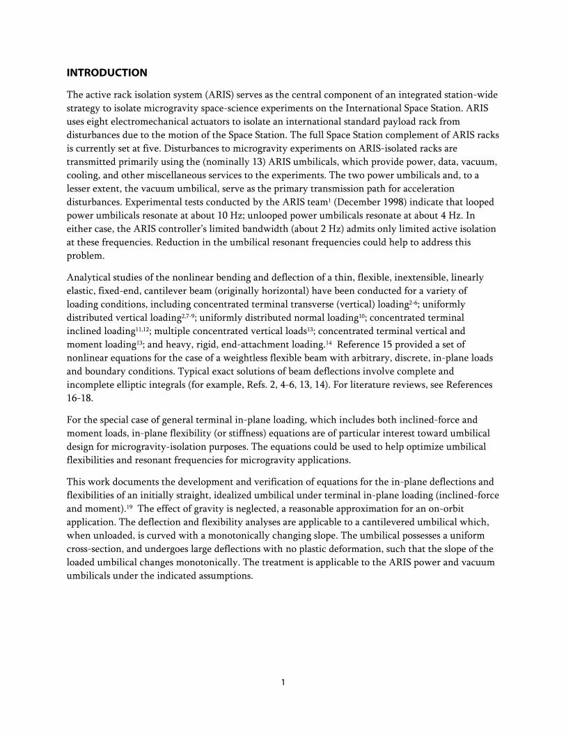
INTRODUCTION
The active rack isolation system (ARIS) serves as the central component of an integrated station-wide strategy to isolate microgravity space-science experiments on the International Space Station. ARIS uses eight electromechanical actuators to isolate an international standard payload rack from disturbances due to the motion of the Space Station. The full Space Station complement of ARIS racks is currently set at five. Disturbances to microgravity experiments on ARIS-isolated racks are transmitted primarily using the (nominally 13) ARIS umbilicals, which provide power, data, vacuum, cooling, and other miscellaneous services to the experiments. The two power umbilicals and, to a lesser extent, the vacuum umbilical, serve as the primary transmission path for acceleration disturbances. Experimental tests conducted by the ARIS team1 (December 1998) indicate that looped power umbilicals resonate at about 10 Hz; unlooped power umbilicals resonate at about 4 Hz. In either case, the ARIS controller’s limited bandwidth (about 2 Hz) admits only limited active isolation at these frequencies. Reduction in the umbilical resonant frequencies could help to address this problem.
Analytical studies of the nonlinear bending and deflection of a thin, flexible, inextensible, linearly elastic, fixed-end, cantilever beam (originally horizontal) have been conducted for a variety of loading conditions, including concentrated terminal transverse (vertical) loading2-6; uniformly distributed vertical loading2,7-9; uniformly distributed normal loading10; concentrated terminal inclined loading11,12; multiple concentrated vertical loads13; concentrated terminal vertical and moment loading13; and heavy, rigid, end-attachment loading.14 Reference 15 provided a set of nonlinear equations for the case of a weightless flexible beam with arbitrary, discrete, in-plane loads and boundary conditions. Typical exact solutions of beam deflections involve complete and incomplete elliptic integrals (for example, Refs. 2, 4-6, 13, 14). For literature reviews, see References 16-18.
For the special case of general terminal in-plane loading, which includes both inclined-force and moment loads, in-plane flexibility (or stiffness) equations are of particular interest toward umbilical design for microgravity-isolation purposes. The equations could be used to help optimize umbilical flexibilities and resonant frequencies for microgravity applications.
This work documents the development and verification of equations for the in-plane deflections and flexibilities of an initially straight, idealized umbilical under terminal in-plane loading (inclined-force and moment).19 The effect of gravity is neglected, a reasonable approximation for an on-orbit application. The deflection and flexibility analyses are applicable to a cantilevered umbilical which, when unloaded, is curved with a monotonically changing slope. The umbilical possesses a uniform cross-section, and undergoes large deflections with no plastic deformation, such that the slope of the loaded umbilical changes monotonically. The treatment is applicable to the ARIS power and vacuum umbilicals under the indicated assumptions.
2
PROBLEM STATEMENT
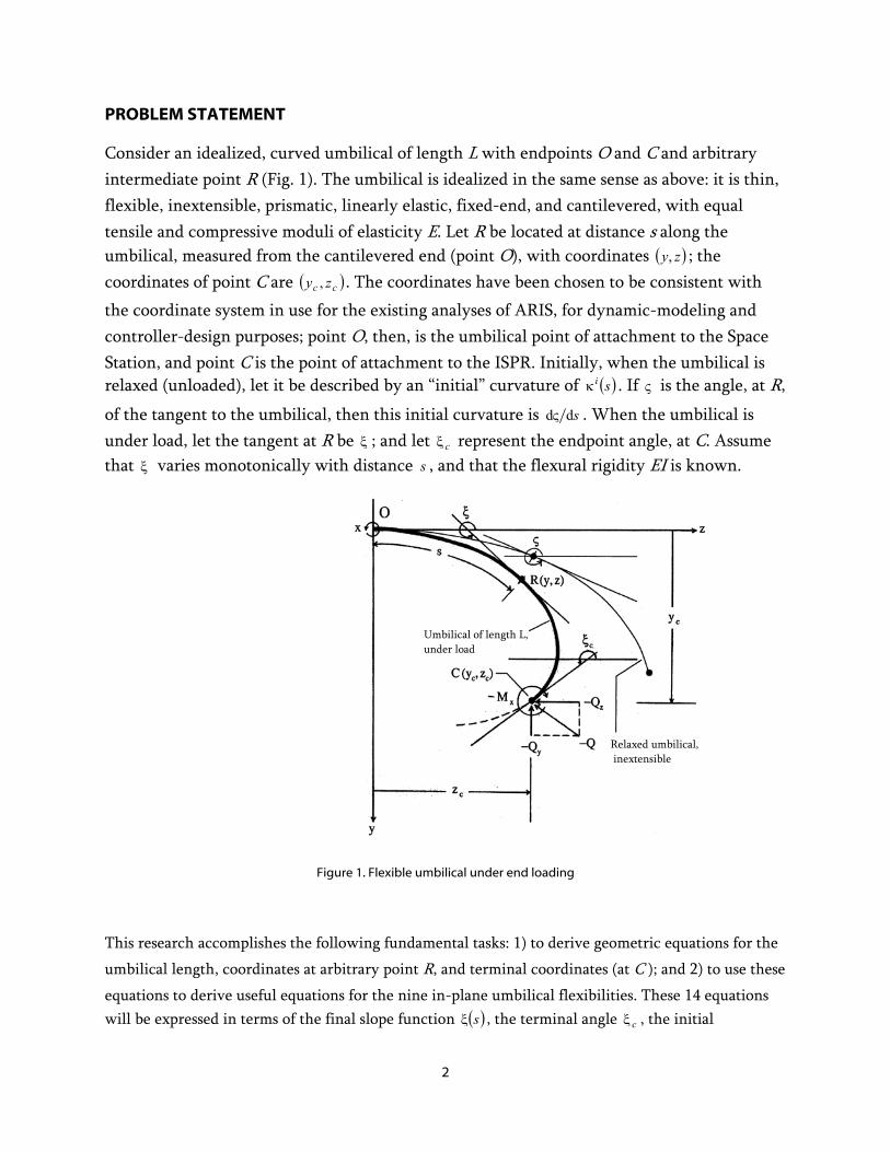
Consider an idealized, curved umbilical of length L with endpoints O and C and arbitrary intermediate point R (Fig. 1). The umbilical is idealized in the same sense as above: it is thin, flexible, inextensible, prismatic, linearly elastic, fixed-end, and cantilevered, with equal tensile and compressive moduli of elasticity E. Let R be located at distance s along the umbilical, measured from the cantilevered end (point O), with coordinates ( )zy, ; the coordinates of point C are ( )cc zy , . The coordinates have been chosen to be consistent with the coordinate system in use for the existing analyses of ARIS, for dynamic-modeling and controller-design purposes; point O, then, is the umbilical point of attachment to the Space Station, and point C is the point of attachment to the ISPR. Initially, when the umbilical is relaxed (unloaded), let it be described by an “initial” curvature of ( )siκ . If ς is the angle, at R,
of the tangent to the umbilical, then this initial curvature is sddς . When the umbilical is under load, let the tangent at R be ξ ; and let cξ represent the endpoint angle, at C. Assume that ξ varies monotonically with distance s , and that the flexural rigidity EI is known.
Figure 1. Flexible umbilical under end loading
This research accomplishes the following fundamental tasks: 1) to derive geometric equations for the
umbilical length, coordinates at arbitrary point R, and terminal coordinates (at C ); and 2) to use these
equations to derive useful equations for the nine in-plane umbilical flexibilities. These 14 equations will be expressed in terms of the final slope function ( )sξ , the terminal angle cξ , the initial
Umbilical of length L, under load
Relaxed umbilical, inextensible
3
(unloaded) curvature function ( )siκ , the unloaded terminal curvature icκ , and arbitrary in-plane
loads at C. The loads are as follows: forces yQ and zQ (assumed to be positive in the positive y- and z-
directions, respectively), and moment xM (assumed to be positive in the counter-clockwise direction,
about the positive x-axis).
EQUATIONS OF UMBILICAL GEOMETRY
At point R the moment equation is
( ) ( ) ⎟⎠⎞
⎜⎝⎛ ς
−ξ
=−−−+=−dsd
dsdEIzzQyyQMM cyczx . (1)
Differentiating with respect to s, observing that
ξ−= sindd
sy (2)
and ξ= cosdd
sz , (3)
and using the shorthand notation ξ=ξ sins and ξ=ξ cosc , one obtains
( )ξξ +=ς
−ξ cQsQ
EIss yz1
dd
dd
2
2
2
2. (4)
Integrating Equation (4) with respect to s yields
( ) 1
22 1dd
21
dd
21 CcQsQ
EIss zy +−=⎟⎠⎞
⎜⎝⎛ ς
−⎟⎠⎞
⎜⎝⎛ ξ
ξξ , (5)
where 1C is an integration constant. At point C, Equation (1) becomes
CR
x ssEIM
→
⎟⎠⎞
⎜⎝⎛ ς
−ξ
=dd
dd , (6)
leading to CR
x
CR sEIM
s →→
ς+=
ξdd
dd . (7)
4
Upon applying this boundary condition to Equation (5) and rearranging, one has
( )cc
cQsQEIds
ddsd
EIM
C zy
CR
xξξ
→
−−⎥⎥⎦
⎤
⎢⎢⎣
⎡⎟⎠⎞
⎜⎝⎛ ς
−⎟⎟⎠
⎞⎜⎜⎝
⎛ ς+=
121 22
1 , (8)
such that Equation (5) can now be solved for sddξ :
( ) ( )⎪⎩
⎪⎨⎧
⎥⎥⎦
⎤
⎢⎢⎣
⎡−−−±=
ccccQssQ
EIs zy ξξξξξ 2
dd ,2/1
2/1222
ηκκκ ±=⎪⎭
⎪⎬⎫⎥⎦
⎤⎢⎣
⎡⎟⎠⎞⎜
⎝⎛−⎟
⎠⎞⎜
⎝⎛+⎟⎟
⎠
⎞⎜⎜⎝
⎛++
ic
iic
x
EIM (9)
where the radicand η is nonnegative:
( ) ( )cc
ccEIQ
ssEIQ zy
ξξξξ −−−≡η22
.0222
≥⎟⎠⎞⎜
⎝⎛−⎟
⎠⎞⎜
⎝⎛+⎟⎟
⎠
⎞⎜⎜⎝
⎛++
ic
iic
x
EIM
κκκ (10)
Note that 2/1
d0
dη−=
ξ⇔≤
ξs
ds
d , (11)
and that 2/1
dd0
dd
η=ξ
⇔≥ξ
ss. (12)
From Equation (9), η±
ξ=
dds . (13)
Define, for convenience, a “shape kernel,” η±=θ , (14)
where the sign is chosen from the physical considerations of Equations (11) and (12), such that
ξθ= − dd 1s . (15)
(In particular, the upper sign applies when 0dd
≥ξs
; the lower, when 0dd
≤ξs
. This convention will be
used throughout the remainder of the paper.) Equation (15) can be integrated to yield an expression for the umbilical length:
ξθ−== ∫∫π
ξ
− dd2 1
0 c
sLL
. (16)
From Equation (2), ξsssy ξ d-dd 1θ−=−= ξ , (17)
such that ⎟⎟⎠
⎞⎜⎜⎝
⎛ξη±=ξθ= ∫∫
π
ξξ
−π
ξξ
− dd2 2/12 1 ssy (18)
and ⎟⎠⎞
⎜⎝⎛ ξη±=ξθ= ∫∫
π
ξξ
−π
ξξ
− dd2 2/12 1
cc
ssyc . (19)
5
Likewise, Equation (3) yields
⎟⎟⎠
⎞⎜⎜⎝
⎛ξη=ξθ−= ∫∫
π
ξξ
−π
ξξ
− dd2 2/12 1 ccz m (20)
and ⎟⎠⎞
⎜⎝⎛ ξη=ξθ−= ∫∫
π
ξξ
−π
ξξ
− dd2 2/12 1
cc
cczc m . (21)
Together, Equations (16) and (18-21) describe the umbilical geometry as unique functions of the terminal angle cξ ; the terminal loads yQ , zQ , and xM ; and the shape kernel θ .
VALIDATION (SPECIAL CASES)
The umbilical geometric equations, (16) and (18) through (21), can be used to derive equations for umbilical in-plane flexibilities. First, however, it will be shown as a check of the mathematics that the geometric equations simplify in some special cases to known forms [13].
Horizontal Cantilever with Vertical Point Load at Free End:
Consider the case where yQ and xM are both zero; this is Frisch-Fay’s “basic strut” [13, p. 41].
Define, for convenience, zz QP −= . (22)
Equation (16) becomes ( ) ξ−⎟⎟⎠
⎞⎜⎜⎝
⎛= ∫
π
ξ
−ξξ dcc
PEIL
cc
z
2 2/12/1
2, (23)
which can be rewritten as ξ⎟⎠⎞
⎜⎝⎛ ξ
−ξ
⎟⎟⎠
⎞⎜⎜⎝
⎛= ∫
π
ξ
−
dP
EILc
c
z
2 2/122
2/1
2sin
2sin
8. (24)
Let 2
sin cp ξ≡ (25)
and select φ such that 2
sinsin ξ=φp . (26)
Taking the differential of the above, ξξ
=φφ ddp2
cos21cos . (27)
From Equations (25) and (26), ( )φ−=ξ
−ξ 2222 sin1
2sin
2sin pc ; (28)
as ξ varies from ξc to 2π, φ varies from 2π
to π. In this range,
( ) sin1cos2/12 φ−=φ− (29)
6
and ( ) 2/122 sin12
cos φ−=ξ
− p , (30)
so that ( ) 2/122 sin1
cos2
φ−
φφ−=ξ
p
dpd . (31)
Finally, using Equations (28) and (31) in Equation (24), and simplifying, one obtains the following result:
)(1 pKk
L = , (32)
where EIP
k z=2 , (33)
and ( ) ςς−=π=−π
∫ dppFpK2/12/
0
22 sin1)2/,()( . (34)
)( pK and F (p, φ), respectively, are Legendre’s complete and incomplete elliptic integrals of the 1st kind [13, p. 5]. Equation (32) is the solution previously reported in [13], page 41.
Horizontal Cantilever with Horizontal Point Load at Free End:
Consider next the case where zQ and xM are both zero. Equation (16) becomes
( ) ξ−⎟⎟⎠
⎞⎜⎜⎝
⎛= ∫
π
ξ
−ξξ dss
QEIL
cc
y
2 2/12/1
2. (35)
Introduce φ and positive parameter p such that ( ) 2/sin12cp ξ−≡ (36)
and 2/1
22sin1sin ⎟⎟
⎠
⎞⎜⎜⎝
⎛ ξ−≡φ
p. (37)
Squaring the above yields φ=ξ− 22 sin2sin1 p . (38)
Taking the differential, φφφ−=ξξ dpd cossin4cos 2 , (39)
so that ( )
φξ−
φφ−=ξ dpd
2/12
2
sin1
cossin4. (40)
From Equation (38) one obtains ( )φ−=ξ+ 22 sin12sin1 p . (41)
7
Equations (38) and (41) together yield
( ) ( ) 2/1222/12 sin1sin2sin1 φ−φ=ξ− pp . (42)
As ξ varies from ξc to 2π, φ varies from 2π
to 2
1sin 1
p− . Using Equation (42) in (40) yields
( ) 2/122 sin1
cos2
φ−
φφ−=ξ
p
dpd . (43)
Obtaining expressions for cξsin and ξsin from Equations (36) and (38), respectively, and substituting from these and Equation (40) into Equation (35), one obtains the following result:
φ⎟⎠⎞⎜
⎝⎛ φ−⎟
⎟⎠
⎞⎜⎜⎝
⎛=
−π
∫ dpQEIL
my
2/1222/2/1
sin1 , (44)
where 2
1sin 1
pm −= . (45)
In terms of elliptic integrals,
[ ]),()(2/1
mpFpKQEIL
y−⎟
⎟⎠
⎞⎜⎜⎝
⎛= , (46)
the solution previously reported in [13], page 42.
EQUATIONS OF UMBILICAL FLEXIBILITY
Nature of Dependencies on Flexural Rigidity EI
It will now be shown that, for constant values of L , cξ , cy , and cz , that is, umbilical length and
terminal geometry, the following expressions are also constants: EIQy ,
EI
Qz , and EIM x . This will have
important implications for umbilical shapes and flexibilities.
For convenience, define the following variables:
EIQy=α1 , (47)
EIQz=α2 , (48)
ic
x
EIM
κ+=α3 , (49)
8
cc
sc ξξ α+α=α 214 , (50)
and ( ) ( )225
ic
i κ−κ=α . (51)
In the case of multiple umbilicals, let an additional subscript indicate the umbilical number: e.g., ijα ,
jθ , jy , jcy , jcξ . These symbols will be used in the subsequent development.
Consider now two umbilicals of uniform cross section, with identical lengths and terminal geometries, but different flexural rigidities EI and (thus) different (nonzero) terminal loads. In particular,
021 >== LLL , (52)
ccc yyy == 21 , (53)
ccc zzz == 21 , (54)
and ccc ξ=ξ=ξ 21 , (55)
but ( ) ( )21 EIEI ≠ . (56)
Then 22 1
22 1
11 dd LLcc
=ξθ−=ξθ−= ∫∫π
ξ
−π
ξ
− , (57)
22 1
22 1
11 dd cc yssycc
=ξθ=ξθ= ∫∫π
ξξ
−π
ξξ
− , (58)
and 22 1
22 1
11 dd cc zcczcc
=ξθ−=ξθ−= ∫∫π
ξξ
−π
ξξ
− , (59)
where ( ) ( ) ( )[cc
ccss jjjj ξξξξ −α−−α±=ξθ 21 222/1
523 ⎥⎦
⎤⎟⎠⎞⎜
⎝⎛ ++ jj αα . (60)
From orthogonality of the constant (unity), sine, and cosine functions in Equations (57-59), respectively,
21 θ=θ . (61)
That is, with uniform cross sections and identical umbilical attachment angles,
21
21
21
21
θ=θ⇒⎪⎭
⎪⎬
⎫
===
cc
cc
zzyyLL
. (62)
It can be shown by simple substitution that the “only if” statement of Equation (62) is, in fact, “if and only if” ( )⇔ .
Using Equation (60), one can expand Equation (61) as follows:
9
( ) ( ) ( )( ) ( ) ( ) .22
22
2522322212
5123121111
θ=α+α+−α−−α±=
α+α+−α−−α±=θ
ξξξξ
ξξξξ
cc
cc
ccss
ccss (63)
Squaring and applying orthogonality as before, one concludes that
⎪⎩
⎪⎨
⎧
α−α=α−αα=αα=α
⇒θ=θ
5223251
231
2221
1211
21 . (64)
Again, it can be shown by simple substitution that this relationship is actually if and only if.
In summary,
⎪⎩
⎪⎨
⎧
α−α=α−αα=αα=α
⇔θ=θ⇔⎪⎭
⎪⎬
⎫
===
5223251
231
2221
1211
21
21
21
21
cc
cc
zzyyLL
. (65)
If the umbilicals also have identical initial curvatures, that is, for
( ) ( ) Lsss ii ≤≤∀κ=κ 021 , (66)
one has that ( ) ( )ss 5251 α=α , (67)
such that
⎪⎩
⎪⎨
⎧
α±=αα=αα=α
⇔θ=θ⇔⎪⎭
⎪⎬
⎫
===
3231
2221
1211
21
21
21
21
cc
cc
zzyyLL
. (68)
Equation (68) can be strengthened further as follows.
From Equation (7), CRs →
ξ=α
dd
3 . (69)
Also, from Equations (9) and (14),
Lsss
≤≤∀⎟⎠⎞
⎜⎝⎛ ξ
=⎟⎠⎞
⎜⎝⎛ ξ
⇔θ=θ 0dd
dd
2121 . (70)
Therefore, for 21 θ=θ , one can conclude that
32313231 α=α⇔α±=α , (71)
In conclusion, if the two umbilicals have identical initial curvatures, Equation (65) reduces to the following:
⎪⎩
⎪⎨
⎧
α=αα=αα=α
⇔θ=θ⇔⎪⎭
⎪⎬
⎫
===
3231
2221
1211
21
21
21
21
cc
cc
zzyyLL
. (72)
10
Equations (70) and (72) have the following physical significance: for a slender, terminally loaded umbilical (assuming only in-plane loading) that has a uniform cross section; a given, monotonically varying initial (i.e., relaxed) curvature; and a specified terminal geometry; changing the flexural rigidity by an arbitrary factor γ changes all terminal loads by the same factor without changing the umbilical shape. The implications for in-plane umbilical flexibilities will be explored in the next section.
FLEXIBILITY EQUATIONS
For a given terminal geometry ( cξ , cy , and cz ), one can now differentiate Equations (16), (19), and (21) with respect to the three terminal loads to yield expressions for the nine in-plane translational flexibilities. For convenience define the following “flexibility integrals”:
ξθ=β ∫π
ξ
− d2 3
1c
, (73)
ξθ=β ξ
π
ξ
−∫ d2 3
2 cc
, (74)
ξθ=β ∫π
ξξ
− d2 3
3c
s , (75)
ξθ=β ∫π
ξξ
− d2 23
4c
c , (76)
ξθ=β ∫π
ξ ξξ− d
2 35
c
sc , (77)
and ξθ=β ∫π
ξξ
− d2 23
6c
s , (78)
where, from Equations (10) and (14),
( ) ( ) 2321 22 α+−α−−α±=θ ξξξξ cc
ccss . (79)
According to Leibnitz’ Rule,
( ) ( )( )
( )
( )
( )∫ ∫ ξξ
∂∂
=ξξ∂∂ xg
xf
xg
xfdxF
xdxF
x,, ( ) ( )
xxgxgxF
∂∂
+ )(, ( ) ( )xxfxfxF
∂∂
− )(, . (80)
Applying Equation (80) to Equation (16), and substituting from Equations (47-51) and (73-78), one obtains the following expressions for the rotational flexibilities:
⎥⎥⎦
⎤
⎢⎢⎣
⎡
βαα
β−βα=
∂ξ∂ ξ
143
133
1mm
cs
EIQy
c , (81)
11
⎥⎥⎦
⎤
⎢⎢⎣
⎡
βαα
β−βα±=
∂ξ∂ ξ
143
123
1mc
c
EIQz
c , (82)
and ⎥⎥⎦
⎤
⎢⎢⎣
⎡
βααβαα
=∂ξ∂
143
133
1mm
EIM x
c . (83)
Applying Leibnitz’ Rule now to Equations (19) and (21), and substituting from Equations (81-83), one obtains the remaining six (translational) flexibility equations. The translational flexibilities are as follows:
( ) ( )⎥⎥⎦
⎤
⎢⎢⎣
⎡
⎟⎟⎠
⎞⎜⎜⎝
⎛
βαα
βααβ−β−β−β
−=
∂∂ ξ
ξξ143
3431336 1
1m
mc
cc
sss
EIQy
y
c , (84)
( ) ( )⎥⎥⎦
⎤
⎢⎢⎣
⎡
⎟⎟⎠
⎞⎜⎜⎝
⎛
βαα
βααβ−β−β−β=
∂∂ ξ
ξξ143
3431235 1
1m
mc
cc
scc
EIQy
z
c , (85)
⎥⎥⎦
⎤
⎢⎢⎣
⎡
⎟⎟⎠
⎞⎜⎜⎝
⎛
βαα
βααβ−β
α−=
∂∂ ξ
143
34313
3
1mm
cs
EIMy
x
c , (86)
( ) ( )⎥⎥⎦
⎤
⎢⎢⎣
⎡
⎟⎟⎠
⎞⎜⎜⎝
⎛
βαα
βααβ−β−β−β=
∂∂ ξ
ξξ143
2431325 1
1m
mc
cc
css
EIQz
y
c , (87)
( ) ( )⎥⎥⎦
⎤
⎢⎢⎣
⎡
⎟⎟⎠
⎞⎜⎜⎝
⎛
βαα
βααβ−β−β−β
−=
∂∂ ξ
ξξ143
2431224 1
1m
mc
cc
ccc
EIQz
z
c , (88)
and ⎥⎥⎦
⎤
⎢⎢⎣
⎡
⎟⎟⎠
⎞⎜⎜⎝
⎛
βαα
βααβ−β
α=
∂∂ ξ
143
24312
3
1m
mc
c
EIMz
x
c . (89)
An example derivation of a translational flexibility is provided in the Appendix.
END-STATE VERIFICATION
To verify the expressions for end-state geometry [i.e., Equations (16), (19), and (21)], a set of combined end-loads yQ , zQ , and xM was initially selected, for an example umbilical, with the results to be compared to those of a corresponding finite-element simulation. The loads were then varied proportionally by use of a load-magnification factor λ to produce a family of loading conditions for comparison purposes.
The example umbilical has a rectangular cross-section, and forms a quarter circle of radius ρ in its relaxed configuration, with assigned values for ρ , for length L , and for flexural rigidity EI. The finite-element model comprises 40 equally-sized triangular shell elements composed of a linearly elastic material of assigned Young’s modulus E , and Poisson’s ratio ν . In particular, the selected
12
umbilical parameters are mm 662.63=ρ , mm 100=L , 2mmN 1250 ⋅=EI , 212 m/N105.7 ⋅=E , and .28.0=ν Its cross-sectional width is 2mm; and its height (i.e., shell thickness), 0.1 mm. The assigned
end-loads are N01.0 λ=yQ , N01.0 λ−=zQ , and mm,N25 ⋅λ−=xM where λ varies from 0.01 to 1.0, in
increments of 0.01.
Calculations were made of the terminal geometry ( )ccc zy ξ,, , from the analytical expressions [Eqs. (16), (19), and (21)], for each value of λ ,using an iterative process in which an initial guess was made for the end-angle cξ , followed by formation of the shape kernel θ [Eqs. (10) and (14)], and by calculation of the resulting length L [using a numerical approximation of Equation (16)]. Based on the error in L, a new estimate for cξ was determined by adding an amount proportional to the calculated error. The iterations were continued until the percent error calculated for L was less than 7100.1 −⋅ . After convergence, the end coordinates ( )cc zy , were calculated using Equations (19) and (21). The resulting terminal geometry is presented in Figure 2a, as a function of λ , by solid lines.
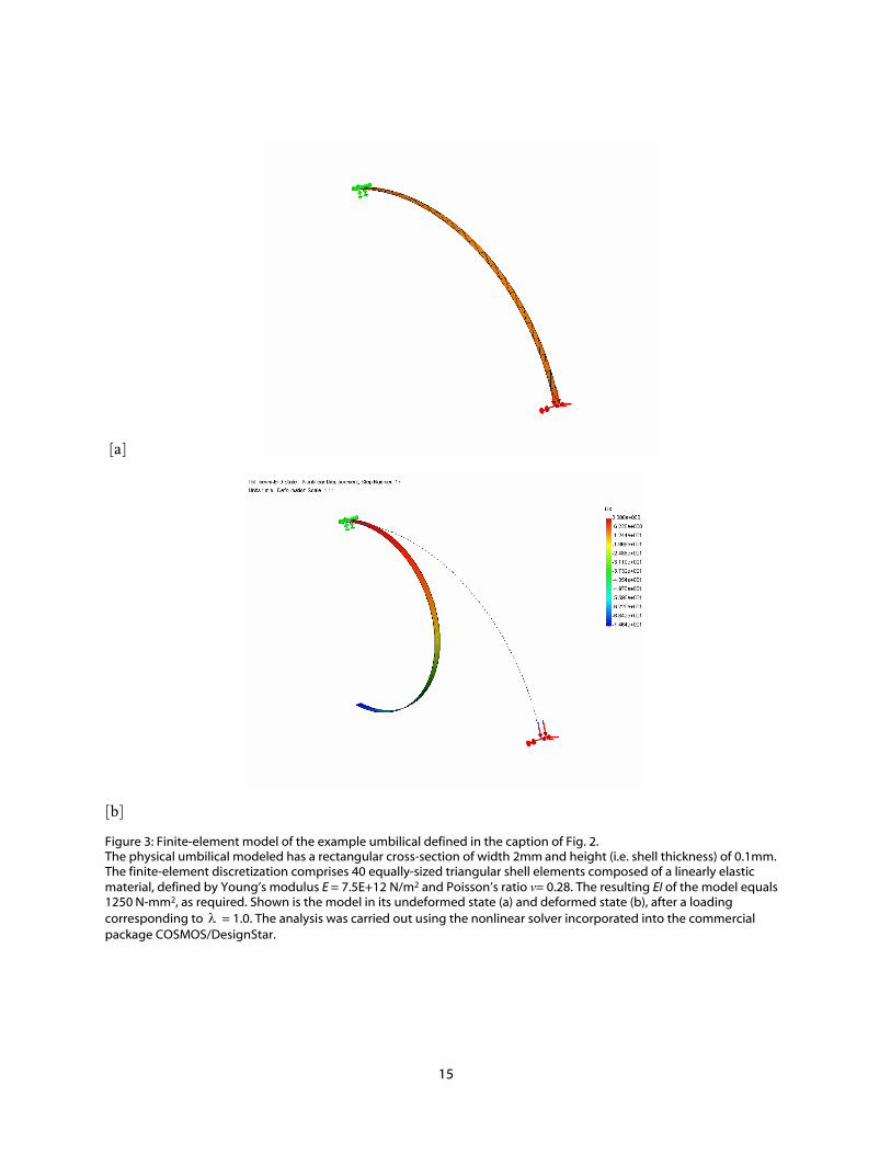
The finite element model was then used to verify the terminal geometry calculated above, by determining the end coordinates ( )cc zy , for the various values of λ . The results are shown as markers in Figure 2a. The results from the analytical model (solid lines) and those from the finite-element model were found to be in excellent agreement. Figure 3 shows the initial and final configurations of the example umbilical, for 1=λ .

13
0.1 0.2 0.3 0.4 0.5 0.6 0.7 0.8 0.9 1-10
0 10 20 30 40 50 60 70
End State
yc
10ξc
zc(a)
0.1 0.2 0.3 0.4 0.5 0.6 0.7 0.8 0.9 1
-150
-100
-50
0
50
100
150
200
Flexibility
∂yc/ ∂Qy
∂yc/ ∂Qz
100 ∂yc/ ∂Mx (b)
0.1 0.2 0.3 0.4 0.5 0.6 0.7 0.8 0.9 1-100 -50
0 50
100 150 200 250 300 350
λ
Flexibility
∂ z c / ∂ Q y
∂ z c / ∂ Q z
100 ∂ z c / ∂ M x
(c)
0.1 0.2 0.3 0.4 0.5 0.6 0.7 0.8 0.9 1
-1
0
1
2
3
4
5
6
7
8
λ
Flexibility
∂ξc/ ∂Qy
∂ξc/ ∂Qz
100 ∂ξc/ ∂Mx
(d)
Figure 2: End-state and flexibilities versus load factor λ for curved (¼-circle) umbilicals with flexural rigidity EI=1250N-
mm2, length L=100mm, radius of curvature mm662.63=ρ (curvature -1mm 01571.0−=κ i ), and end-loadings
N01.0 λ=yQ , N01.0 λ−=zQ , and mmN25 ⋅λ−=xM , where λ varies from 0.01 to 1.0 in increments of 0.01. Solid
lines denote results calculated using the analytical expressions; markers denote results calculated using either the finite-element model (a) or finite-difference approximations (b, c, and d).
FLEXIBILITY VERIFICATION
Once the end-states had been verified, they could be used in turn to verify the flexibility equations [Eqs. (81) through (89)], by finite difference approximations. The pertinent finite difference approximations follow:
)2(oh|| ,,,,
+∆
−=
∂∂ ∆+
y
MQQcMQQQc
y
c
Q
yy
Qy xzyxzyy , (90)
)2(oh|| ,,,,
+∆
−=
∂∂ ∆+
z
MQQcMQQQc
z
c
Q
yy
Qy xzyxzzy , (91)
14
)2(oh|| ,,,,
+∆
−=
∂∂ ∆+
x
MQQcMMQQc
x
c
M
yy
My xzyxxzy , (92)
)2(oh|| ,,,,
+∆
−=
∂∂ ∆+
y
MQQcMQQQc
y
c
Q
zz
Qz xzyxzyy , (93)
)2(oh|| ,,,,
+∆
−=
∂∂ ∆+
z
MQQcMQQQc
z
c
Q
zz
Qz xzyxzzy , (94)
)2(oh|| ,,,,
+∆
−=
∂∂ ∆+
x
MQQcMMQQc
x
c
M
zz
Mz xzyxxzy , (95)
)2(oh|| ,,,,
+∆
ξ−ξ=
∂ξ∂ ∆+
y
MQQcMQQQc
y
c
QQxzyxzyy , (96)
)2(oh|| ,,,,
+∆
ξ−ξ=
∂ξ∂ ∆+
z
MQQcMQQQc
z
c
QQxzyxzzy , (97)
and )2(oh|| ,,,,
+∆
ξ−ξ=
∂ξ∂ ∆+
x
MQQcMMQQc
x
c
MMxzyxxzy . (98)
The finite-difference approximations to the flexibilities [Eqs. (90) through (98)] were calculated over the selected range of values for λ using the verified end-states that had been calculated previously. The value chosen for each of the increments ,, zy QQ ∆∆ and xM∆ corresponds to a 0.01% change
from the respective nominal value. Finite-difference results for the flexibilities are shown as markers in Figures 2b, c, and d. The analytical models (shown by solid lines) are seen to be in excellent agreement with the finite-difference calculations.
15
[a]
[b]
Figure 3: Finite-element model of the example umbilical defined in the caption of Fig. 2. The physical umbilical modeled has a rectangular cross-section of width 2mm and height (i.e. shell thickness) of 0.1mm. The finite-element discretization comprises 40 equally-sized triangular shell elements composed of a linearly elastic material, defined by Young’s modulus E = 7.5E+12 N/m2 and Poisson’s ratio v= 0.28. The resulting EI of the model equals 1250 N-mm2, as required. Shown is the model in its undeformed state (a) and deformed state (b), after a loading corresponding to λ = 1.0. The analysis was carried out using the nonlinear solver incorporated into the commercial package COSMOS/DesignStar.
16
IMPLICATIONS FOR UMBILICAL DESIGN
The foregoing equations can be used as an aid for designing umbilicals to minimize stiffness. First,
the flexural rigidity can be used to adjust all stiffnesses by a common factor. Since all of the iα ’s
and iβ ’s are invariant with flexural rigidity, the square-bracketed factors of the flexibility
equations, Equations (56) through (64), are all independent of flexural rigidity. It is evident from
these equations, then, that reductions in EI will produce proportional reductions in all terminal
loads and in-plane stiffnesses. Second, for given umbilical length L, and endpoint conditions cξ ,
cy , and cz , Equations (16), (19), and (21) can be solved for the loads yQ , zQ , and xM . These
loads can be determined and used iteratively in the flexibility equations to optimize the umbilical
flexibilities (or, equivalently, the corresponding stiffnesses) using L as a parameter. Third, the
umbilical designer can use these equations to determine optimal L, cξ combinations. Although
the angle cξ is fixed at about 225 deg for ARIS (in the home, or centered, position); L and cξ
optimization could suggest better angles for future designs.
CONCLUSION
This research has presented equations for the shape and flexibilities of a slender umbilical on
orbit, that is, such that gravity can be neglected, under general, terminal, in-plane loading
conditions of sufficient magnitude to cause large deformations. The relaxed (preloaded) umbilical
was assumed to be curved, with monotonically varying slope, and to have a uniform cross section.
The loaded umbilical is assumed to undergo no plastic deformation. All in-plane stiffnesses were
shown to be proportional to the flexural rigidity EI. The geometric end-state equations and
umbilical flexibility expressions were verified numerically for an initially circular umbilical,
subject to in-plane end-loading conditions. An approach was offered for using umbilical length
and terminal geometry (endpoint locations and slopes) to optimize these umbilical stiffnesses. The
basic geometric equations for an initially straight cantilever were shown to reduce to previously
published results for special loading conditions.

17
APPENDIX: SAMPLE DERIVATION OF A FLEXIBILITY EQUATION
From Equation (19), the y-coordinate of terminal point C is
ξθ= ∫π
ξξ
− d2 1
c
syc , (19, A-1)
where
( ) ( ) ( ) ( )[ ] 2/15
2321 22 α+α+−α−−α±=ξθ ξξξξ cc
ccss , (60, A-2)
for EIQy=α1 , (47, A-3)
EIQz=α2 , (48, A-4)
ic
x
EIM
κ+=α3 , (49, A-5)
and ( ) ( )225
ic
i κ−κ=α . (51, A-6)
Taking the partial derivative of Equation (A-1) with respect to yQ , one has
⎟⎠⎞
⎜⎝⎛ ξθ
∂∂
=∂∂
∫π
ξξ
−2 1 dc
sQQ
y
yy
c . (A-7)
Applying Leibnitz’ Rule,
( )yyy
c
Qss
QQy
c ∂π∂
⎟⎠⎞⎜
⎝⎛θ+ξ⎟
⎠⎞⎜
⎝⎛θ
∂∂
=∂∂
π→ξξ
−π
ξξ
−
∫2
d2
12 1
y
c
Qs
c∂ξ∂
⎟⎠⎞⎜
⎝⎛θ−
ξ→ξξ
−1 . (A-8)
The right-hand side of this equation will next be evaluated term by term.
The integrand of the first right-hand-side term is
( ) ( ) ( )⎥⎥⎦
⎤
⎢⎢⎣
⎡
∂ξ∂
α+α−−θ−=θ∂∂
ξξξξ−
ξξ−
y
c
y Qscss
EIss
Q ccc 2131 1 , (A-9)
so that the integral itself becomes
=ξ⎟⎠⎞⎜
⎝⎛θ
∂∂
∫π
ξξ
−2 1 dc
sQy
⎟⎠⎞
⎜⎝⎛ ξθ−ξθ
−∫ ∫
π
ξ
π
ξ
−ξξ
−ξ
2 2 332 dd1c c
csss
EI( )
y
c
Qssc
ccc ∂
ξ∂ξθα+α+ ∫
π
ξ
−ξξξ
2 321 d . (A-10)
The second right-hand-side term of Equation (A-8) is zero, since 2π is a constant.
18
The third right-hand-side term is
( ) ( )y
c
y
c
Qs
Qs
cc ∂
ξ∂α±−=
∂ξ∂
θ− ξ−
ξ→ξξ− 1
31 , (A-11)
where the sign accompanying 13−α is that of slope sddξ . By similar application of Leibnitz’ Rule
to the equation ξθ−= ∫π
ξ
− d2 1
c
L ,(16, A-12)
one has
⎥⎥⎥⎥
⎦
⎤
⎢⎢⎢⎢
⎣
⎡
ξθαα
ξθ−ξθα=
∂ξ∂
∫∫∫
π
ξ
−
π
ξ
−ξ
π
ξξ
−
d1
dd
2 343
2 32 3
3
c
cc
c
ss
EIQy
c
m
m. (A-13)
Substituting from Equations (A-9), (A-11), and (A-13) into Equation (A-8), and using Equations (73), (75), (78) to re-express the result in terms of the si 'β , one obtains the form given in Equation (84):
( ) ( )⎥⎥⎦
⎤
⎢⎢⎣
⎡
⎟⎟⎠
⎞⎜⎜⎝
⎛
βαα
βααβ−β−β−β
−=
∂∂ ξ
ξξ143
3431336 1
1m
mc
cc
sss
EIQy
y
c . (84, A-14)
The other flexibility equations can be determined analogously.
19
REFERENCES
1Edberg, D. L., and Wilson, B. W., “Design and Testing of Reduced-Stiffness Umbilicals for Space Station Microgravity Isolation,” AIAA Paper 2000-1408, April 2000.
2Hummel, F. H., and Morton, W. B., “On the Large Deflection of Thin Flexible Strips and the Measurement of Their Elasticity,” Philosophical Magazine, Ser. 7, Vol. 17, 1927, pp. 348-357.
3Gross, S., and Lehr, E., Die Federn, V. D. I. Verlag, Berlin, Germany, 1938.
4Barten, H. J., “On the Deflection of a Cantilever Beam,” Quarterly of Applied Mathematics, Vol. 2 (2), 1944, pp. 168-171.
5Barten, H. J., “On the Deflection of a Cantilever Beam,” Quarterly of Applied Mathematics, Vol. 3 (3), 1945, pp. 275, 276.
6Bisshopp, K. E., and Drucker, D. C., “Large Deflections of Cantilever Beams,” Quarterly of Applied Mathematics, Vol. 3 (3), Oct. 1945, pp. 272-275.
7Bickley, W. G., “The Heavy Elastica,” Philosophical Magazine, Ser. 7, Vol. 17, 1934, pp. 603-622.
8Rohde, F. V., “Large Deflections of a Cantilever Beam with a Uniformly Distributed Load,” Quarterly of Applied Mathematics, Vol. 11, 1953, pp. 337, 338.
9Schmidt, R., and Dadeppo, D. A., “Large Deflections of Heavy Cantilever Beams and Columns,” Quarterly of Applied Mathematics, Oct. 1970, 441-444.
10Mitchell, T. P., “The Non-Linear Bending of Thin Rods,” Journal of Applied Mechanics, Vol. 26, 1959, pp. 40-43.
11Beth, R. A., and Wells, C. P., “Finite Deflections of a Cantilever Strut,” Journal of Applied Physics, Vol. 22, 1951, pp. 742-746.
12Massoud, M. F., “On the Problem of Large Deflection of a Cantilever Beam,” International Journal of Mechanical Sciences, Vol. 8, Feb. 1966, pp. 141-143.
13Frisch-Fay, R., Flexible Bars, Butterworths, London, 1962, pp. 5, 42.
14Antman, S. S., Marlow, R. S., and Vlahacos, C. P., “The Complicated Dynamics of Heavy Rigid Bodies Attached to Deformable Rods,” Quarterly of Applied Mathematics, Vol. 56, No. 3, Sep. 1998, pp. 431-460.
15Manuel, F. S., and Lee, S. L., “Flexible Bars Subjected to Arbitrary Discrete Loads and Boundary Conditions,” Journal of the Franklin Institute, Vol. 285 (6), 1968, pp. 452-474.
16Rojahn, C., “Large Deflections of Elastic Beams,” Degree of Engineer Thesis, Stanford University, June 1968.
17Gorski, W., “A Review of the Literature and a Bibliography on Finite Elastic Deflections of Bars,” Institute of Engineers, Australia: Civil Engineering Transactions, Vol. CE18, 1976, pp. 74-85.

20
18Libai, A., and Simmonds, J. G., The Nonlinear Theory of Elastic Shells, 2nd ed., Cambridge Univ. Press, Cambridge, England, U.K., 1998.
19Hampton, R. D., Quraishi, N., and Rupert, J. K., “Flexibility Equations for Active Rack Isolation System Umbilicals with Planar End Loading (TN),” AIAA Journal, Vol. 39 (10), Oct. 2001, pp. 2024-2027.


REPORT DOCUMENTATION PAGE Form Approved OMB No. 0704-0188
Public reporting burden for this collection of information is estimated to average 1 hour per response, including the time for reviewing instructions, searching existing data sources, gathering and maintaining the data needed, and completing and reviewing the collection of information. Send comments regarding this burden estimate or any other aspect of this collection of information, including suggestions for reducing this burden, to Washington Headquarters Services, Directorate for Information Operations and Reports, 1215 Jefferson Davis Highway, Suite 1204, Arlington, VA 22202-4302, and to the Office of Management and Budget, Paperwork Reduction Project (0704-0188), Washington, DC 20503.
1. AGENCY USE ONLY (Leave Blank) 2. REPORT DATE 3. REPORT TYPE AND DATES COVERED January 2005 NASA Technical Manual
4. TITLE AND SUBTITLE 5. FUNDING NUMBERSDeformation and Flexibility Equations for ARIS Umbilicals Idealized as Planar Elastica
6. AUTHOR(S) R. David Hampton, Michael J. Leamy, Paul J. Bryant, Naveed Quraishi
7. PERFORMING ORGANIZATION NAME(S) AND ADDRESS(ES) 8. PERFORMING ORGANIZATION REPORT NUMBERS
Lyndon B. Johnson Space Center Houston, Texas 77058
S-948
9. SPONSORING/MONITORING AGENCY NAME(S) AND ADDRESS(ES) 10. SPONSORING/MONITORING AGENCY REPORT NUMBER
National Aeronautics and Space Administration Washington, DC 20546-0001
TM-2004-213155
11. SUPPLEMENTARY NOTES
12a. DISTRIBUTION/AVAILABILITY STATEMENT 12b. DISTRIBUTION CODE
Category: 67 Available from the NASA Center for AeroSpace Information (CASI) 7121 Standard Hanover, MD 21076-1320
13. ABSTRACT (Maximum 200 words) The International Space Station relies on the active rack isolation system (ARIS) as the central component of an integrated, station-wide strategy to isolate microgravity space-science experiments. ARIS uses electromechanical actuators to isolate an international standard payload rack from disturbances due to the motion of the Space Station. Disturbances to microgravity experiments on ARIS-isolated racks are transmitted primarily via the ARIS power and vacuum umbilicals. Experimental tests indicate that these umbilicals resonate at frequencies outside the ARIS controller’s bandwidth at levels of potential concern for certain microgravity experiments. Reduction in the umbilical resonant frequencies could help to address this issue. This work documents the development and verification of equations for the in-plane deflections and flexibilities of an idealized umbilical (thin, flexible, inextensible, cantilever beam) under end-point, in-plane loading (inclined-force and moment). The effect of gravity is neglected due to the on-orbit application. The analysis assumes an initially curved (not necessarily circular), cantilevered umbilical with uniform cross-section, which undergoes large deflections with no plastic deformation, such that the umbilical slope changes monotonically. The treatment is applicable to the ARIS power and vacuum umbilicals under the indicated assumptions.
14. SUBJECT TERMS 15. NUMBER OF PAGES
16. PRICE CODE
ISS, Space Station, ARIS, microgravity, umbilicals, planar elastica 20
17. SECURITY CLASSIFICATION OF REPORT
18. SECURITY CLASSIFICATION OF THIS PAGE
19. SECURITY CLASSIFICATION OF ABSTRACT
20. LIMITATION OF ABSTRACT
Unclassified Unclassified Unclassified Unlimited Standard Form 298 (Rev Feb 89) (MS Word Mar 97) Prescribed by ANSI Std. 239-18 298-102
NSN 7540-01-280-5500