Embed Size (px)
Citation preview
HEAT RECOVERY VENTILATION UNITS with INTEGRATED AIR/AIR HEAT PUMP (CLIMATIZATION and DEHUMIDIFICATION
TECHNICAL DATAindoor air quality and energy saving
DEH e DEH-HIDRONICDEH-ENT. e DEH-ENT.-HIDRONIC
DEH 2DEH 2-HIDRONIC
DEH 1 DEH 1-HIDRONIC
CLASS
B
B
UNIT
DEH 1-ENT.DEH 1-ENT.-HIDRONIC
DEH 2-ENT.DEH 2-ENT.-HIDRONIC
CLASS
B
B
UNIT
A
A+
B
CDE
F
G
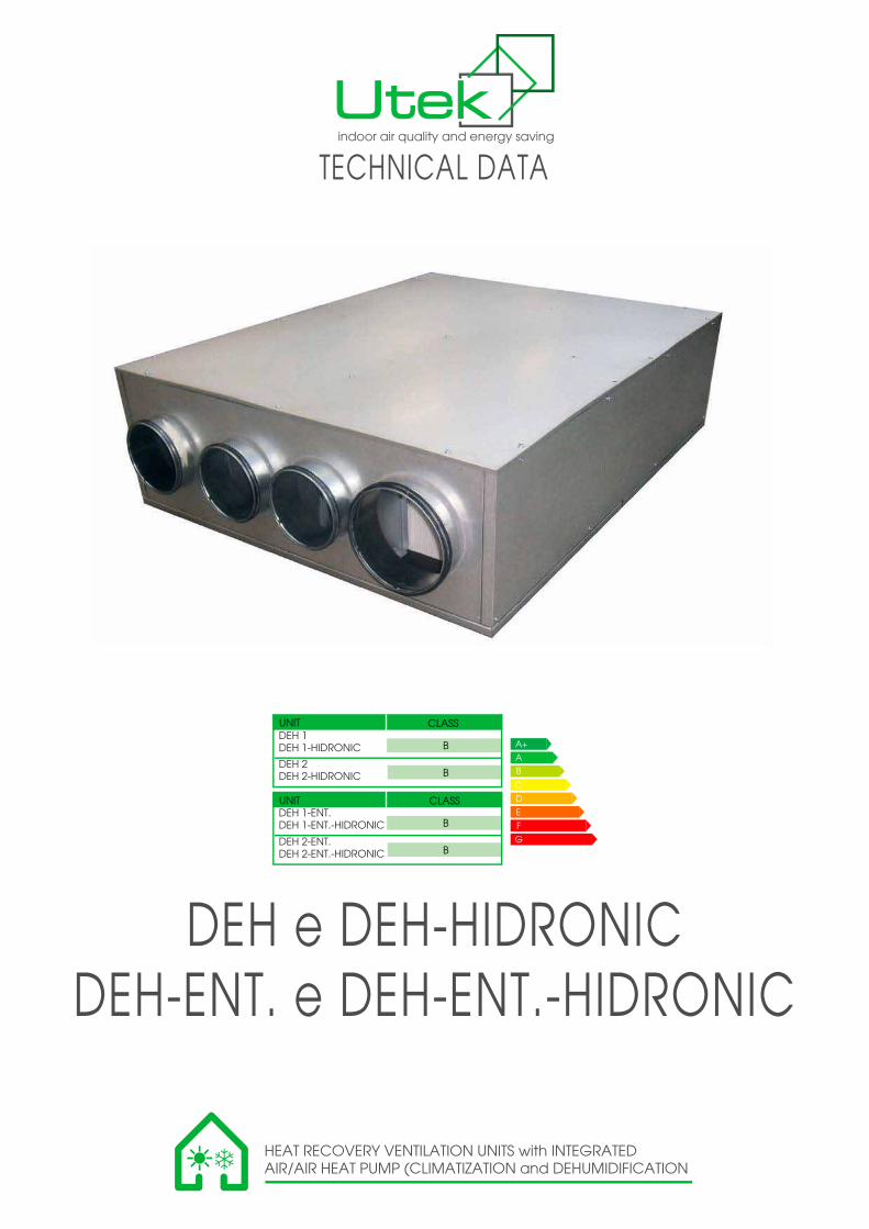
DEHDehumidification unit and air change with heat recoveryresidential ventilation unit wiyh heat recovery and dehumidification in combination with radiant cooling systems- Ceiling installation- Horizontal configuration
Range: n. 2 models:- DEH-1 with air flow rate from 300 to 150 m³ / h- DEH-2 with air flow rate from 500 to 250 m³ / h
DESCRIPTION- Aluzinc self-supporting panels, sides in double panels insulated with foam polyurethane, 23 mm thick, top and bottom sheet single (insulated),
- Aluzinc drip tray condensation- Basic configuration: electronic microprocessor and electrical cabinet pre-wired on the machine (plug-nplay)- Configuration with CO2 probe for automatic control of the flow of fresh air (optional)- Refrigerant circuit with hermetic compressor that uses refrigerant R134A
ELECTRIC FANS- Electronic motors Fan EC plug fans 230V-1-50 / 60Hz high efficiency (ErP-2015)
HEAT EXCHANGER- Polypropylene exchanger counterflow high efficiency. DEH is also available in enthalpy version to recover the latent heat (humidity) in
addition to the sensible heat (temperature).
FILTERS- Filters: air extraction / renewal / recirculation: class Coarse 65% (G4) / ePM1 70% (F7) / Coarse 65% (G4) (EN 779)
DEHUMIDIFY CONFIGURATION view from above
VMC CONFIGURATION view from above
2
®
®
expulsion air
fresh air
exhaust air
Recirculation air
supply air
expulsion air
fresh air
exhaust air
supply air
0,00 0,02 0,04 0,06 0,08 0,10 0,12 0,14 0,16
0
100
200
300
400
500
600
700
0
50
100
150
200
250
300
350
400
450
0 100 200 300 400 500 600
Air flow [m3/s]Po
we
r [W
]
Pre
ssu
re [
Pa
]
Air flow [m3/h]
Max RefMin Dehumidif.
Max Ref Min Dehumidif.
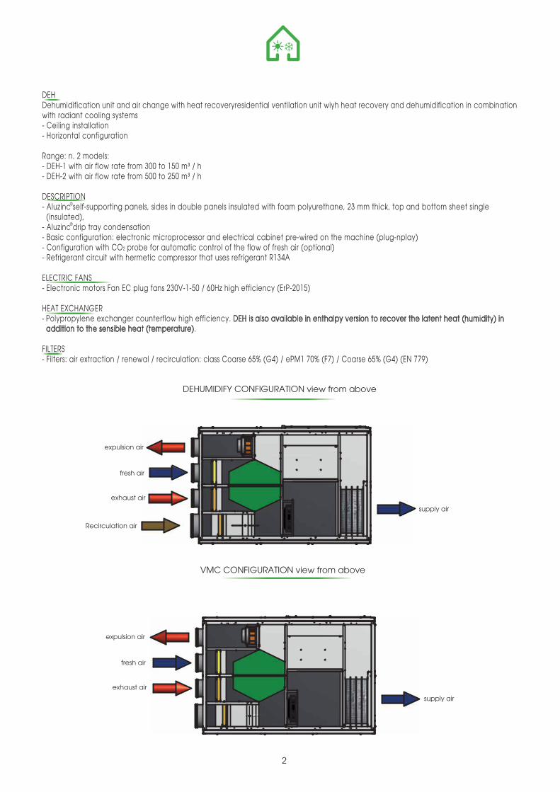
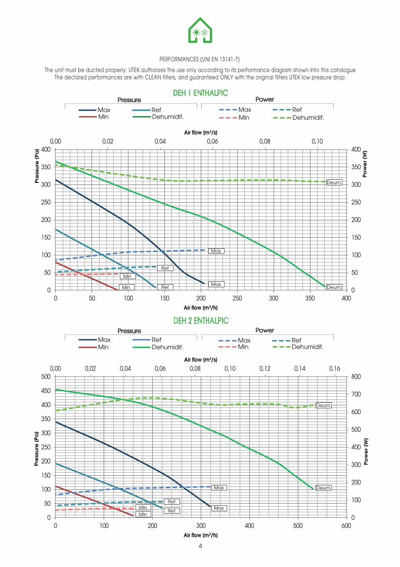
PERFORMANCES (UNI EN 13141-7)
DEH 1
The unit must be ducted properly: UTEK authorizes the use only according to its performance diagram shown into this catalogueThe declared performances are with CLEAN filters, and guaranteed ONLY with the original filters UTEK low pressure drop.
3
Pressure Power
Max RefMin Dehumidif.
Max Ref Min Dehumidif.
Pressure Power
0,00 0,02 0,04 0,06 0,08 0,10
0
50
100
150
200
250
300
350
400
0
50
100
150
200
250
300
350
400
0 50 100 150 200 250 300 350 400
Air flow [m3/s]
Pow
er
[W]
Pre
ssu
re [
Pa
]
Air flow [m3/h]
DEH 2
Deum.
Ref.
Max
Max
Min
Min Ref. Deum.
Max
Max
Ref.
Ref.
Deum.
Deum.
Min
Min
0,00 0,02 0,04 0,06 0,08 0,10 0,12 0,14 0,16
0
100
200
300
400
500
600
700
800
0
50
100
150
200
250
300
350
400
450
500
0 100 200 300 400 500 600
Air flow [m3/s]Po
we
r [W
]
Pre
ssu
re [
Pa
]
Air flow [m3/h]
0,00 0,02 0,04 0,06 0,08 0,10
0
50
100
150
200
250
300
350
400
0
50
100
150
200
250
300
350
400
0 50 100 150 200 250 300 350 400
Air flow [m3/s]
Po
we
r [W
]
Pre
ssu
re [
Pa
]
Air flow [m3/h]
Max RefMin Dehumidif.
Max Ref Min Dehumidif.
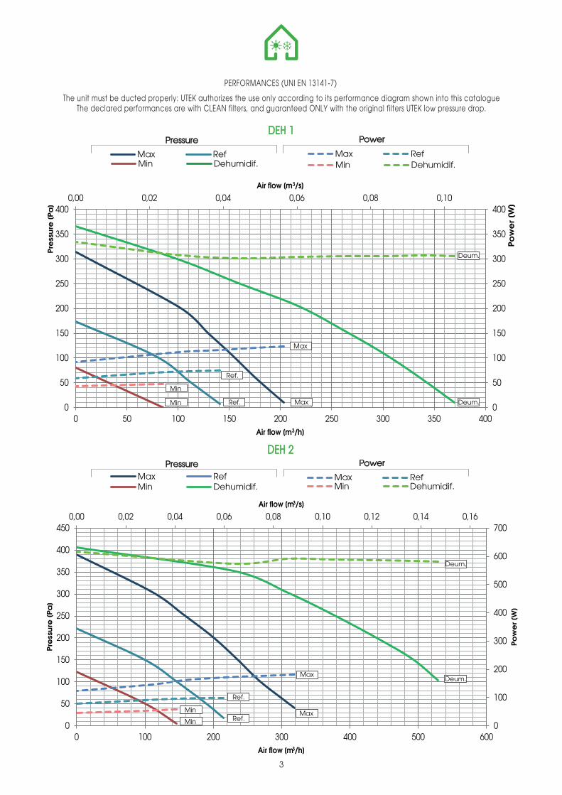
PERFORMANCES (UNI EN 13141-7)
DEH 1 ENTHALPIC
The unit must be ducted properly: UTEK authorizes the use only according to its performance diagram shown into this catalogueThe declared performances are with CLEAN filters, and guaranteed ONLY with the original filters UTEK low pressure drop.
4
Pressure Power
Max RefMin Dehumidif.
Max Ref Min Dehumidif.
Pressure PowerDEH 2 ENTHALPIC
Deum.
Deum.
Max
Max
Ref.
Ref.
Min
Min
Deum.
Deum.Max
MaxRef.
Ref.MinMin
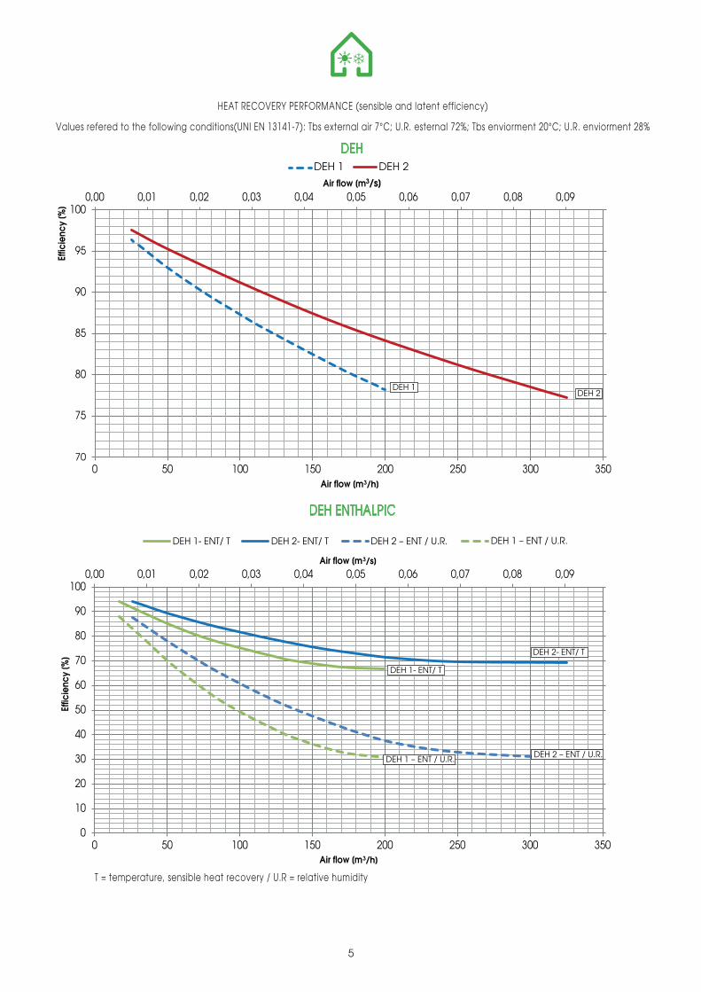
HEAT RECOVERY PERFORMANCE (sensible and latent efficiency)
Values refered to the following conditions(UNI EN 13141-7): Tbs external air 7°C; U.R. esternal 72%; Tbs enviorment 20°C; U.R. enviorment 28%
5
0,00 0,01 0,02 0,03 0,04 0,05 0,06 0,07 0,08 0,09
0
10
20
30
40
50
60
70
80
90
100
0 50 100 150 200 250 300 350
Air flow [m3/s]
Effic
ienc
y [%
]
Air flow [m3/h]
0,00 0,01 0,02 0,03 0,04 0,05 0,06 0,07 0,08 0,09
70
75
80
85
90
95
100
0 50 100 150 200 250 300 350
Air flow [m3/s]
Effic
ienc
y [%
]
Air flow [m3/h]
DEH 1 DEH 2
DEH
DEH ENTHALPIC
DEH 2DEH 1
DEH 1- ENT/ T
DEH 2- ENT/ T
DEH 1 – ENT / U.R. DEH 2 – ENT / U.R.
DEH 1- ENT/ T DEH 2- ENT/ T DEH 2 – ENT / U.R. DEH 1 – ENT / U.R.
T = temperature, sensible heat recovery / U.R = relative humidity
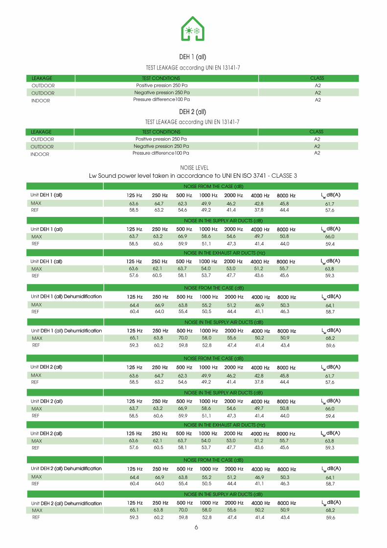
TEST LEAKAGE according UNI EN 13141-7
DEH 1 (all)
OUTDOOR
INDOOR
OUTDOOR
TEST CONDITIONS
Negative pression 250 Pa
Pressure difference100 Pa
Positive pression 250 Pa A2
A2
A2
CLASSLEAKAGE
TEST LEAKAGE according UNI EN 13141-7
DEH 2 (all)
OUTDOOR
INDOOR
OUTDOOR
TEST CONDITIONS
Negative pression 250 Pa
Pressure difference100 Pa
Positive pression 250 Pa A2
A2A2
CLASSLEAKAGE
NOISE LEVELLw Sound power level taken in accordance to UNI EN ISO 3741 - CLASSE 3
6
MAX REF
NOISE IN THE SUPPLY AIR DUCTS (dB)
NOISE FROM THE CASE (dB)
125 Hz 250 Hz 500 Hz 1000 Hz 2000 Hz
63,6 64,7 62,3 49,9 46,2 42,8 45,8
4000 Hz
61,7 58,5 63,2 54,6 49,2 41,4 37,8 44,4 57,6
8000 Hz
L dB(A)w
125 Hz 250 Hz 500 Hz 1000 Hz 2000 Hz
63,7 63,2 66,9 58,6 54,6 49,7 50,8
4000 Hz
66,0
58,5 60,6 59,9 51,1 47,3 41,4 44,0 59,4
8000 Hz L dB(A)w
NOISE IN THE EXHAUST AIR DUCTS (Hz)
125 Hz 250 Hz 500 Hz 1000 Hz 2000 Hz
63,6 62,1 63,7 54,0 53,0 51,2 55,7
4000 Hz
63,8 57,6 60,5 58,1 53,7 47,7 43,6 45,6 59,3
8000 Hz L dB(A)w
MAX REF
MAX REF
Unit DEH 1 (all)
Unit DEH 1 (all)
Unit DEH 1 (all)
MAX REF
NOISE IN THE SUPPLY AIR DUCTS (dB)
NOISE FROM THE CASE (dB)
125 Hz 250 Hz 500 Hz 1000 Hz 2000 Hz
64,4 66,9 63,8 55,2 51,2 46,9 50,3
4000 Hz
64,1 60,4 64,0 55,4 50,5 44,4 41,1 46,3 58,7
8000 Hz
L dB(A)w
125 Hz 250 Hz 500 Hz 1000 Hz 2000 Hz
65,1 63,8 70,0 58,0 55,6 50,2 50,9
4000 Hz
68,2
59,3 60,2 59,8 52,8 47,4 41,4 43,4 59,6
8000 Hz L dB(A)w
MAX REF
Unit DEH 1 (all) Dehumidification
Unit DEH 1 (all) Dehumidification
MAX REF
NOISE IN THE SUPPLY AIR DUCTS (dB)
NOISE FROM THE CASE (dB)
125 Hz 250 Hz 500 Hz 1000 Hz 2000 Hz
63,6 64,7 62,3 49,9 46,2 42,8 45,8
4000 Hz
61,7 58,5 63,2 54,6 49,2 41,4 37,8 44,4 57,6
8000 Hz
L dB(A)w
125 Hz 250 Hz 500 Hz 1000 Hz 2000 Hz
63,7 63,2 66,9 58,6 54,6 49,7 50,8
4000 Hz
66,0
58,5 60,6 59,9 51,1 47,3 41,4 44,0 59,4
8000 Hz L dB(A)w
NOISE IN THE EXHAUST AIR DUCTS (Hz)
125 Hz 250 Hz 500 Hz 1000 Hz 2000 Hz
63,6 62,1 63,7 54,0 53,0 51,2 55,7
4000 Hz
63,8 57,6 60,5 58,1 53,7 47,7 43,6 45,6 59,3
8000 Hz L dB(A)w
MAX REF
MAX REF
Unit DEH 2 (all)
Unit DEH 2 (all)
Unit DEH 2 (all)
MAX REF
NOISE IN THE SUPPLY AIR DUCTS (dB)
NOISE FROM THE CASE (dB)
125 Hz 250 Hz 500 Hz 1000 Hz 2000 Hz
64,4 66,9 63,8 55,2 51,2 46,9 50,3
4000 Hz
64,1 60,4 64,0 55,4 50,5 44,4 41,1 46,3 58,7
8000 Hz
L dB(A)w
125 Hz 250 Hz 500 Hz 1000 Hz 2000 Hz
65,1 63,8 70,0 58,0 55,6 50,2 50,9
4000 Hz
68,2
59,3 60,2 59,8 52,8 47,4 41,4 43,4 59,6
8000 Hz L dB(A)w
MAX REF
Unit DEH 2 (all) Dehumidification
Unit DEH 2 (all) Dehumidification
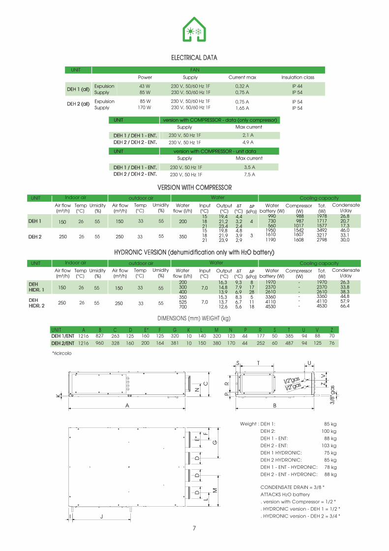
DIMENSIONS (mm) WEIGHT (kg)
230 V, 50/60 Hz 1F 0,32 A
FAN
ExpulsionSupply
ExpulsionSupply
Power Insulation class Supply
230 V, 50/60 Hz 1F 0,75 A
Current max
230 V, 50/60 Hz 1F 0,75 A 230 V, 50/60 Hz 1F
43 W 85 W
85 W 170 W 1,65 A
IP 44IP 54
IP 54IP 54
UNIT
7
55
Indoor air outdoor air Water Cooling capacity
150
250
Temp [°C]
Air flow [m³/h]
Umidity [%]
55
26
26
55150
250
Temp [°C]
Air flow [m³/h]
Umidity [%]
55
33
33
151821151821
19,421,223,419,821,923,9
4,43,22,44,83,92,9
990 730 560
1950 1610 1190
988 987
1017 1542 1607 1608
1978 1717 15773492 3217 2798
26,820,717,346,033,130,0
Output[°C]
Input [°C] [°C]
Compressor [W]
Waterbattery [W]
Tot. [W]
Condensatel/day
UNIT
Indoor air outdoor air Water Cooling capacityUNIT
ELECTRICAL DATA
VERSION WITH COMPRESSOR
[kPa]
4
3
200
350
Waterflow [l/h]
Temp [°C]
Air flow [m³/h]
Umidity [%]
Temp [°C]
Air flow [m³/h]
Umidity [%]
Output[°C]
Input [°C] [°C]
Compressor [W]
Waterbattery [W]
Tot. [W]
Condensatel/day[kPa]
Waterflow [l/h]
DEH 1 (all)
DEH 2 (all)
DEH 1
DEH 2
UNIT A B C D E* F G K L M N P R S T 1216
1216
827
960
263
328
125
160
160
200
125
164
320
381
140
150
10
10
320
380
123
170
44
44
177
252
50
60
385
487
94
94
88
125
70
76DEH 1/ENT
DEH 2/ENT
U V Z
A
F
E*D
DD
L
MG
N
C
B
S T
PR
U
VZ
1/2"gas1/2"gas
I J
K
sa
g"8/3
CONDENSATE DRAIN = 3/8 "
ATTACKS H2O battery
. version with Compressor = 1/2 "
. HYDRONIC version - DEH 1 = 1/2 "
. HYDRONIC version - DEH 2 = 3/4 "
DEHHIDR. 1 55150
250 DEHHIDR. 2 55
26
26
55150
250 55
33
33
1970 2370 2610 3360 4110 4530
------
1970 2370 2610 3360 4110 4530
26,333,838,344,857,966,4
200300400350525700
16,314,813,915,313,712,6
9,37,96,98,36,75,6
817285
1118
7,0
7,0
DEH 1: 85 kg
DEH 2: 100 kg
DEH 1 - ENT: 88 kg
DEH 2 - ENT: 103 kg
DEH 1 HYDRONIC: 75 kg
DEH 2 HYDRONIC: 85 kg
DEH 1 - ENT - HYDRONIC: 78 kg
DEH 2 - ENT - HYDRONIC: 88 kg
Weight :
HYDRONIC VERSION (dehumidification only with H2O battery)
DEH 1 / DEH 1 - ENT. 230 V, 50 Hz 1F
version with COMPRESSOR - data (only compressor)
Supply Max current
DEH 2 / DEH 2 - ENT. 230 V, 50 Hz 1F
UNIT
4,9 A
2,1 A
230 V, 50 Hz 1F
Supply Max current
230 V, 50 Hz 1F 7,5 A
3,5 ADEH 1 / DEH 1 - ENT.DEH 2 / DEH 2 - ENT.
version with COMPRESSOR - unit dataUNIT
*ricircolo
8
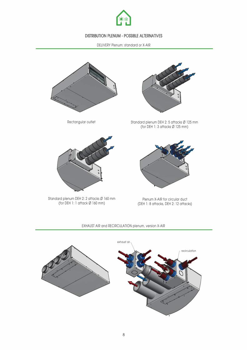
DISTRIBUTION PLENUM - POSSIBLE ALTERNATIVES
DELIVERY Plenum: standard or X-AIR
EXHAUST AIR and RECIRCULATION plenum, version X-AIR
Standard plenum DEH 2: 5 attacks Ø 125 mm(for DEH 1: 3 attacks Ø 125 mm)
Plenum X-AIR for circular duct(DEH 1: 8 attacks, DEH 2: 12 attacks)
PLENUMRIPRESA
PLENUMRICIRCOLO
Rectangular outlet
Standard plenum DEH 2: 2 attacks Ø 160 mm(for DEH 1: 1 attack Ø 160 mm)
exhaust air
recirculation
C
AA
B D E
A
A
T abellaColonna 1 Colonna 2 Colonna 3 Colonna 4 Colonna 5 Colonna 6
UNI T A' A [mm] B [mm] C [mm] D [mm] E [mm]DEH 1 260 700 1220 820 300DEH 2 330 700 1220 960 300
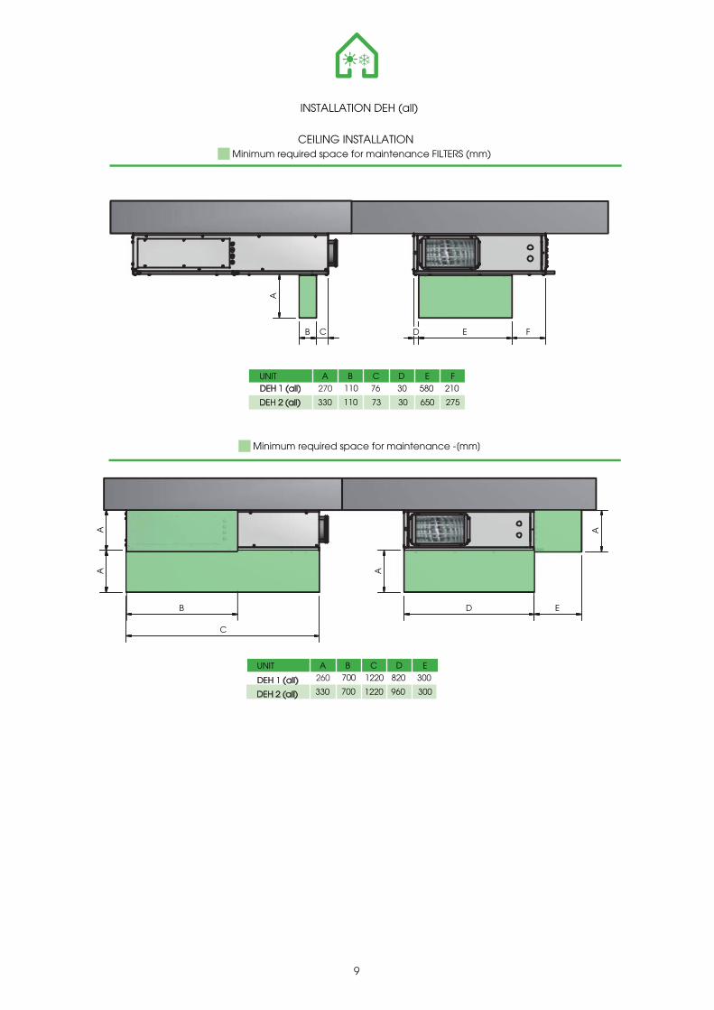
9
INSTALLATION DEH (all)
CEILING INSTALLATIONMinimum required space for maintenance FILTERS (mm)
A B C D E FUNIT270
330
110
110
76
73
30
30
580
650
210
275
CB
A
ED F
Minimum required space for maintenance -[mm]
A B C D EUNIT 260
330
700
700
1220
1220
820
960
300
300
DEH 1 (all)
DEH 2 (all)
DEH 1 (all)
DEH 2 (all)
0,00 0,02 0,04 0,06 0,08
0,0
0,5
1,0
1,5
2,0
2,5
3,0
3,5
4,0
30
32
34
36
38
40
42
44
0 100 200 300 400
Air flow [m3/s]
Wa
ter p
ress
ure
dro
p [k
Pa]
Wat
er o
utle
t tem
pera
ture
[°C
]
Air flow [m3/h]
0,00 0,02 0,04 0,06 0,08
0,0
0,5
1,0
1,5
2,0
2,5
3,0
3,5
4,0
4,5
5,0
5
7
9
11
13
15
17
19
0 100 200 300 400
Portata aria [m3/s]
Wat
er p
ress
ure
drop
[kPa
]
Wat
er o
utle
t tem
pera
ture
[°C
]
Air flow [m3/h]
1,1 kW
1,6 kW
2,2 kW
0,00 0,02 0,04 0,06 0,08
0
5
10
15
20
25
30
0,0
5,0
10,0
15,0
20,0
25,0
0 100 200 300
Air flow [m3/s]
Air
pre
ssur
e d
rop
[Pa
]
Air flow [m3/h]
2,3 kW
2 kW
1,7 kW
0,00 0,02 0,04 0,06 0,08
0
2
4
6
8
10
12
14
16
18
20
25,0
27,0
29,0
31,0
33,0
35,0
37,0
39,0
41,0
43,0
0 100 200 300
Air flow [m3/s]
Air
pres
sure
dro
p [P
a]
Air flow [m3/h]
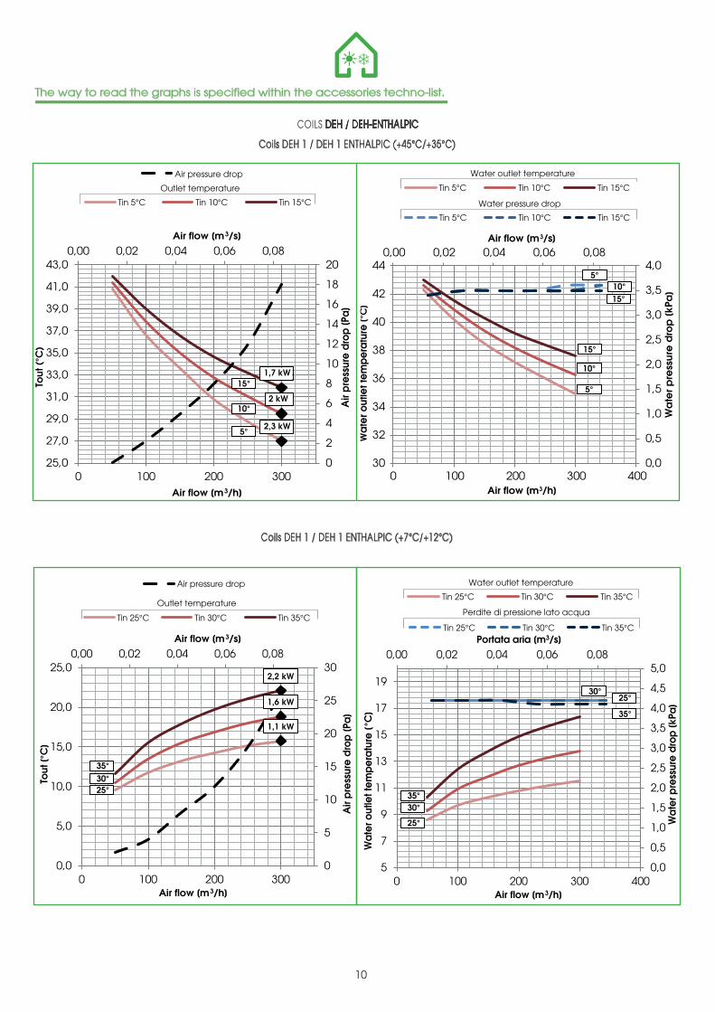
COILS DEH / DEH-ENTHALPIC
Coils DEH 1 / DEH 1 ENTHALPIC (+45°C/+35°C)
Water outlet temperature
Potenza
10
Air pressure drop
Outlet temperature
Water pressure drop
Tin 5°C Tin 10°C Tin 15°C
Coils DEH 1 / DEH 1 ENTHALPIC (+7°C/+12°C)
Air pressure drop
Tin 5°C Tin 10°C Tin 15°C
Tin 5°C Tin 10°C Tin 15°C
Tin 25°C Tin 30°C Tin 35°C
Tout
[°C
]To
ut (
°C)
Potenza
Perdite di pressione lato acqua
Tin 25°C Tin 30°C Tin 35°C
Water outlet temperature
Tin 25°C Tin 30°C Tin 35°COutlet temperature
35°
35°
35°
25°
25°
25°
30°
30°
30°
15°
15°
15°
5°
5°
5°
10°
10°
10°
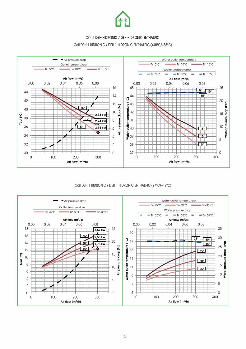
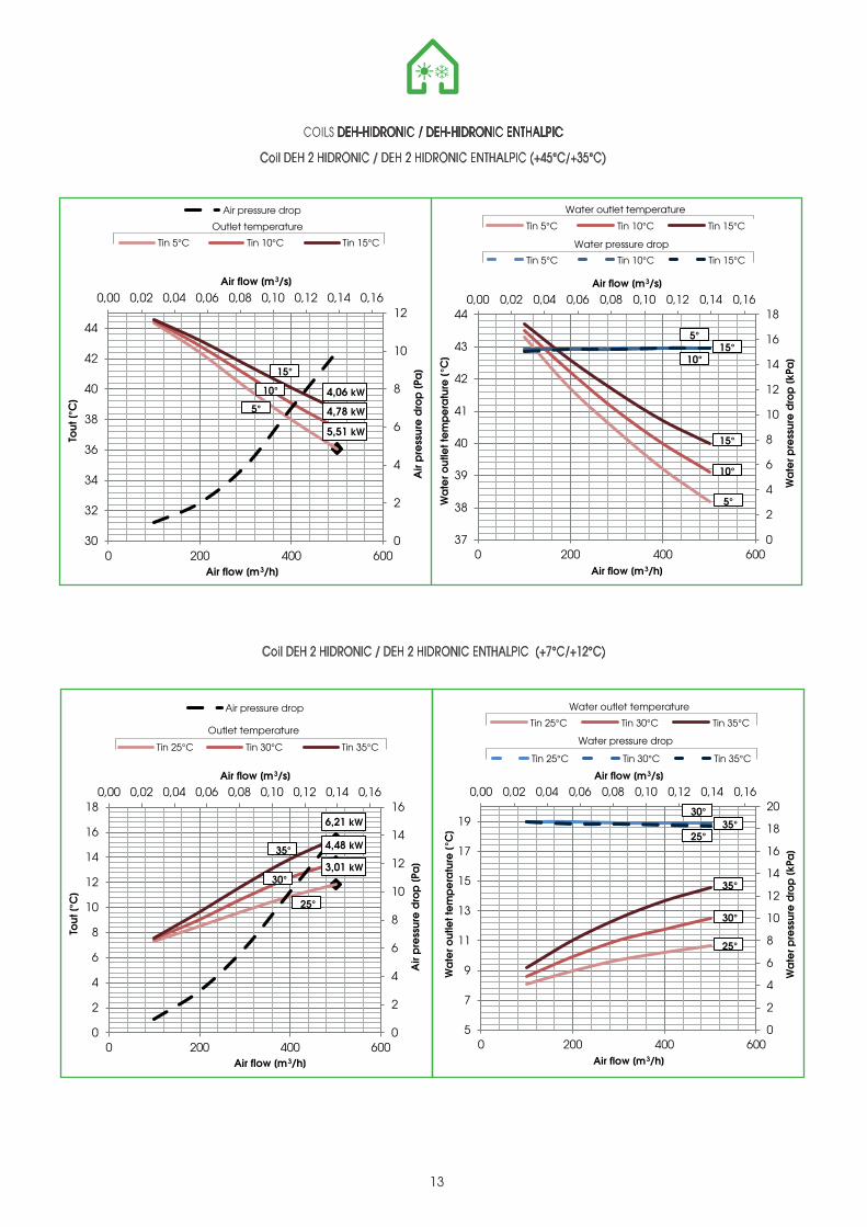
The way to read the graphs is specified within the accessories techno-list.
0,00 0,05 0,10 0,15
0,0
0,5
1,0
1,5
2,0
2,5
3,0
3,5
4,0
4,5
5,0
5
7
9
11
13
15
17
0 200 400 600
Air flow [m³/s]
Wat
er p
ress
ure
drop
[kPa
]
Wat
er o
utle
t tem
pera
ture
[°C
]
Air flow [m³/h]
1,8 kW
2,7 kW
3,7 kW
0,00 0,05 0,10 0,15
0
5
10
15
20
25
0,0
5,0
10,0
15,0
20,0
25,0
0 200 400 600
Air flow [m3/s]
Air
pre
ssur
e d
rop
[Pa
]
Air flow [m3/h]
0,00 0,05 0,10 0,15
0,0
0,5
1,0
1,5
2,0
2,5
30
32
34
36
38
40
42
44
0 200 400 600
Air flow [m3/s]
Wat
er p
ress
ure
drop
[kPa
]
Wat
er o
utle
t tem
pera
ture
[°C
]
Air flow [m3/h]
4 kW
3,4 kW
2,9 kW
0,00 0,05 0,10 0,15
0
2
4
6
8
10
12
14
16
25,0
27,0
29,0
31,0
33,0
35,0
37,0
39,0
41,0
43,0
0 200 400 600
Air flow [m3/s]
Air
pre
ssur
e d
rop
[Pa
]
Air flow [m3/h]
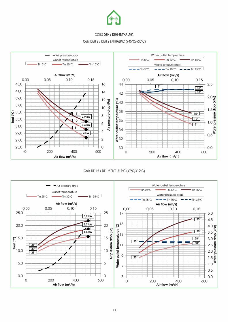
COILS DEH / DEH-ENTHALPIC
Coils DEH 2 / DEH 2 ENTHALPIC (+45°C/+35°C)
Water outlet temperature
Potenza
11
Air pressure drop
Outlet temperature
Water pressure dropTin 5°C Tin 10°C Tin 15°C
Coils DEH 2 / DEH 2 ENTHALPIC (+7°C/+12°C)
Air pressure drop
Tin 5°C Tin 10°C Tin 15°C
Tin 5°C Tin 10°C Tin 15°C
Tin 25°C Tin 30°C Tin 35°C
Tout
[°C
]To
ut (
°C)
Potenza Water pressure drop
Tin 25°C Tin 30°C Tin 35°C
Water outlet temperatureTin 25°C Tin 30°C Tin 35°C
Outlet temperature
15° 15°
15°
5° 5°
5°
10° 10°
10°
35°
25°30°
35°
35°25°
25°
30°
30°
0,00 0,02 0,04 0,06 0,08
0
5
10
15
20
25
30
35
5
7
9
11
13
15
17
19
0 100 200 300 400
Air flow [m3/s]
Wa
ter p
ress
ure
dro
p [k
Pa]
Wa
ter o
utle
t te
mp
era
ture
[°C
]
Air flow [m3/h]
1,73 kW
2,58 kW
3,57 kW
0,00 0,02 0,04 0,06 0,08
0
5
10
15
20
25
0
2
4
6
8
10
12
14
16
18
0 100 200 300
Air flow [m3/s]
Air
pre
ssur
e d
rop
[Pa
]
Tout
[°C
]
Air flow [m3/h]
0,00 0,02 0,04 0,06 0,08
0
5
10
15
20
25
37
38
39
40
41
42
43
44
45
0 100 200 300 400
Air flow [m3/s]
Wa
ter p
ress
ure
dro
p [k
Pa]
Wa
ter o
utle
t te
mp
era
ture
[°C
]
Air flow [m3/h]
3,16 kW
2,74 kW
2,33 kW
0,00 0,02 0,04 0,06 0,08
0
2
4
6
8
10
12
14
16
30
32
34
36
38
40
42
44
0 100 200 300
Air flow [m3/s]
Air
pre
ssur
e d
rop
[Pa
]
Tout
[°C
]
Air flow [m3/h]
COILS DEH-HIDRONIC / DEH-HIDRONIC ENTHALPIC
Coil DEH 1 HIDRONIC / DEH 1 HIDRONIC ENTHALPIC (+45°C/+35°C)
Water outlet temperature
Potenza
12
Air pressure drop
Outlet temperature
Water pressure dropTin 5°C Tin 10°C Tin 15°C
Coil DEH 1 HIDRONIC / DEH 1 HIDRONIC ENTHALPIC (+7°C/+12°C)
Air pressure drop
Tin 5°C Tin 10°C Tin 15°C
Tin 5°C Tin 10°C Tin 15°C
Tin 25°C Tin 30°C Tin 35°CPotenza
Water pressure drop
Tin 25°C Tin 30°C Tin 35°C
Water outlet temperatureTin 25°C Tin 30°C Tin 35°C
Outlet temperature
15°
15°
15°
5°
5°
5°
10°
10°
10°
35°
35°
35°
25°
25°
25°
30°
30°
30°
0,00 0,02 0,04 0,06 0,08 0,10 0,12 0,14 0,16
0
2
4
6
8
10
12
14
16
18
20
5
7
9
11
13
15
17
19
0 200 400 600
Air flow [m3/s]W
ate
r pre
ssur
e d
rop
[kPa
]
Wa
ter o
utle
t te
mp
era
ture
[°C
]
Air flow [m3/h]
3,01 kW
4,48 kW
6,21 kW
0,00 0,02 0,04 0,06 0,08 0,10 0,12 0,14 0,16
0
2
4
6
8
10
12
14
16
0
2
4
6
8
10
12
14
16
18
0 200 400 600
Air flow [m3/s]
Air
pre
ssur
e d
rop
[Pa
]
Tout
[°C
]
Air flow [m3/h]
0,00 0,02 0,04 0,06 0,08 0,10 0,12 0,14 0,16
0
2
4
6
8
10
12
14
16
18
37
38
39
40
41
42
43
44
0 200 400 600
Air flow [m3/s]
Wa
ter p
ress
ure
dro
p [k
Pa]
Wa
ter o
utle
t te
mp
era
ture
[°C
]
Air flow [m3/h]
5,51 kW
4,78 kW
4,06 kW
0,00 0,02 0,04 0,06 0,08 0,10 0,12 0,14 0,16
0
2
4
6
8
10
12
30
32
34
36
38
40
42
44
0 200 400 600
Air flow [m3/s]
Air
pre
ssur
e d
rop
[Pa
]
Tout
[°C
]
Air flow [m3/h]
COILS DEH-HIDRONIC / DEH-HIDRONIC ENTHALPIC
Coil DEH 2 HIDRONIC / DEH 2 HIDRONIC ENTHALPIC (+45°C/+35°C)
Water outlet temperature
Potenza
13
Air pressure drop
Outlet temperature
Water pressure dropTin 5°C Tin 10°C Tin 15°C
Coil DEH 2 HIDRONIC / DEH 2 HIDRONIC ENTHALPIC (+7°C/+12°C)
Air pressure drop
Tin 5°C Tin 10°C Tin 15°C
Tin 5°C Tin 10°C Tin 15°C
Tin 25°C Tin 30°C Tin 35°CPotenza
Water pressure drop
Tin 25°C Tin 30°C Tin 35°C
Water outlet temperatureTin 25°C Tin 30°C Tin 35°C
Outlet temperature
15°
15°
15°
5°
5°
5°
10°
10°
10°
35°
35°
35°
25°
25°
25°
30°
30°
30°
14
CO
LDA
VER
AG
EW
ARM
BB
BB
UV
R -
UV
B
Va
riab
le s
pe
ed
driv
e
Rec
upe
rativ
e
86,0
0,04
2
119
62
0,03
1
50
0,65
3
0,85
Clo
ck
co
ntr
ol (
no
DC
V)
6.2
/ 7.
1
-
UV
R -
UV
B
Va
riab
le s
pe
ed
driv
e
Rec
upe
rativ
e
84,8
0,07
4
177
58
0,05
3
50
0,51
6
0,85
Clo
ck
co
ntr
ol (
no
DC
V)
6.3
/ 4.
7
-
UV
R -
UV
B
Va
riab
le s
pe
ed
driv
e
Rec
up
era
tive
74,1
0,04
2
112
62
0,03
0
50
0,60
4
0,85
Clo
ck
co
ntr
ol (
no
DC
V)
6.5
/ 7.
5
-
UV
R -
UV
B
Va
riab
le s
pe
ed
driv
e
Rec
up
era
tive
71,6
0,07
4
174
58
0,05
6
50
0,44
7
0,85
Clo
ck
co
ntr
ol (
no
DC
V)
6.0
/ 4.
5
-
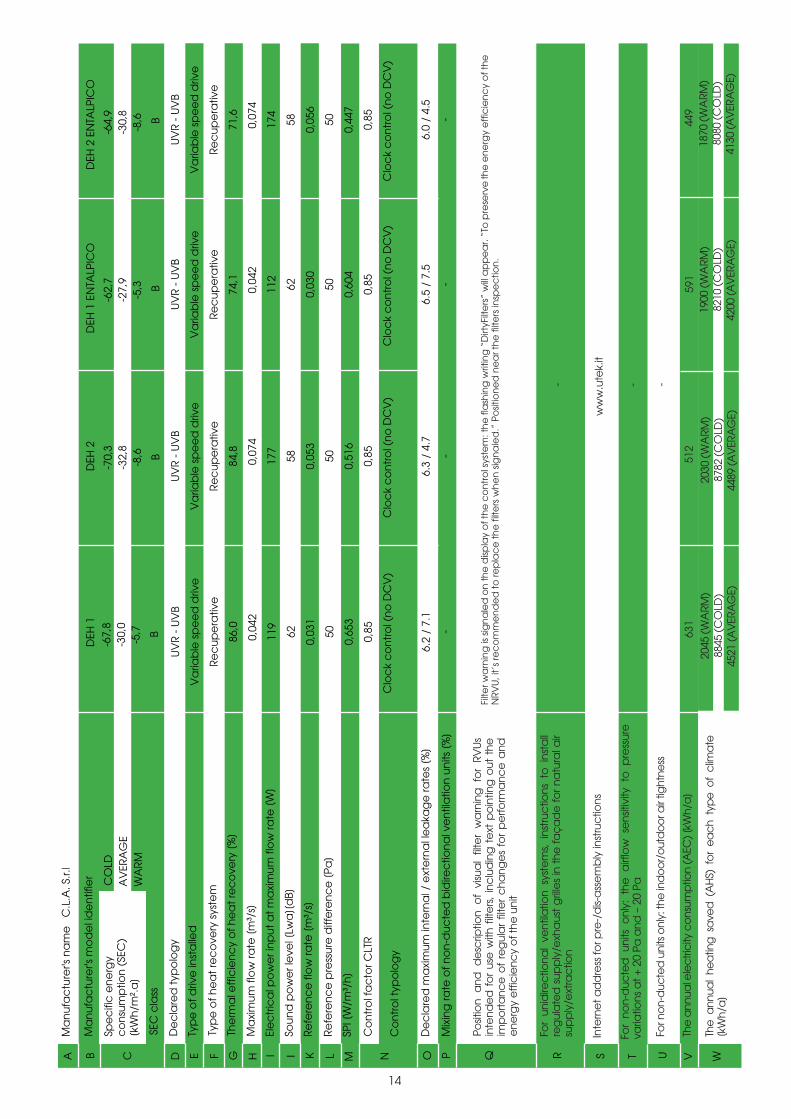
-67,
8-3
0,0
-5,7
-70,
3-3
2,8
-8,6
-62,
7-2
7,9
-5,3
-64,
9-3
0,8
-8,6
DEH
1D
EH 2
DEH
1 E
NTA
LPIC
OD
EH 2
EN
TALP
ICO
Filte
r wa
rnin
g is
sig
na
led
on
the
disp
lay
of t
he
co
ntr
ol s
yste
m: t
he
fla
shin
g w
ritin
g “
Dirt
yFilt
ers
” w
ill a
pp
ea
r. “T
o p
rese
rve
the
en
erg
y e
ffic
ien
cy
of t
he
N
RVU
, it’
s re
co
mm
en
de
d t
o re
pla
ce
th
e fi
lters
wh
en
sig
na
led
.” P
osit
ion
ed
ne
ar t
he
filte
rs in
spe
ctio
n.
ww
w.u
tek.
it
631
512
2045
(W
ARM
)8845
(C
OLD
)4521
(AV
ERA
GE)
2030
(W
ARM
)8782
(C
OLD
)4489
(AV
ERA
GE)
-
591
1900
(W
ARM
)8210
(C
OLD
)4200
(AV
ERA
GE)
- -
449
1870
(W
ARM
)8080
(C
OLD
)4130
(AV
ERA
GE)
A B C D E F G H I I K L M N O P Q R S T U V W
Spe
cifi
c e
ne
rgy
co
nsu
mp
tion
(SE
C)
[kW
h/m
².a
]
De
cla
red
typ
olo
gy
Typ
e o
f driv
e in
sta
lled
Typ
e o
f he
at
rec
ove
ry s
yste
m
The
rma
l eff
icie
nc
y o
f he
at
rec
ove
ry [
%]
Ma
xim
um fl
ow
rate
[m
³/s]
Ele
ctr
ica
l po
we
r in
put
at
ma
xim
um fl
ow
rate
[W
]
Soun
d p
ow
er l
eve
l [Lw
a][
dB]
Refe
ren
ce
flo
w ra
te [
m³/
s]
Refe
ren
ce
pre
ssur
e d
iffe
ren
ce
[Pa
]
SPI [
W/m
³/h
]
Co
ntr
ol f
ac
tor C
LTR
Co
ntr
ol t
ypo
log
y
De
cla
red
ma
xim
um in
tern
al /
ext
ern
al l
ea
kag
e ra
tes
[%]
Mix
ing
rate
of n
on
-duc
ted
bid
irec
tion
al v
en
tila
tion
un
its [
%]
Ma
nuf
ac
ture
r's m
od
el i
de
ntif
ier
Ma
nuf
ac
ture
r's n
am
e C.L.A. S
.r.l
SEC
cla
ss
Posit
ion
and
de
scrip
tion
of
visu
al
filte
r w
arn
ing
fo
r RV
Us
inte
nde
d f
or
use
with
filt
ers
, in
clu
din
g t
ext
po
intin
g o
ut t
he
imp
ort
anc
e o
f re
gul
ar
filte
r c
hang
es
for
pe
rform
anc
e a
nd
ene
rgy
effi
cie
ncy
of t
he u
nit
For
unid
irec
tiona
l ve
ntila
tion
syst
em
s, i
nstr
uctio
ns t
o i
nsta
ll re
gul
ate
d s
upp
ly/e
xha
ust
gril
les
in t
he f
aç
ad
e f
or n
atu
ral a
ir su
pp
ly/e
xtra
ctio
n
Inte
rne
t ad
dre
ss fo
r pre
-/d
is-a
sse
mb
ly in
stru
ctio
ns
For
non-
duc
ted
uni
ts o
nly:
the
airf
low
se
nsiti
vity
to
pre
ssur
e
varia
tions
at +
20
Pa a
nd –
20
Pa
For n
on-
duc
ted
uni
ts o
nly:
the
ind
oo
r/o
utd
oo
r air
tight
ness
The
ann
ual e
lec
tric
ity c
ons
ump
tion
(AEC
) [kW
h/a
]
The
ann
ual
hea
ting
sa
ved
(A
HS)
fo
r e
ac
h ty
pe
of
clim
ate
[k
Wh/
a]
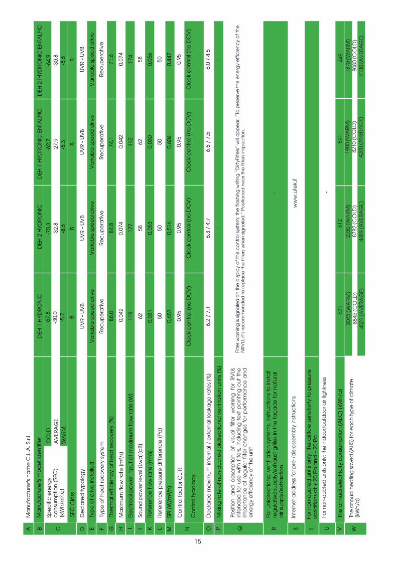
15
Spe
cifi
c e
ne
rgy
co
nsu
mp
tion
(SE
C)
[kW
h/m
².a
]
CO
LDA
VER
AG
EW
ARM
De
cla
red
typ
olo
gy
Typ
e o
f driv
e in
sta
lled
Typ
e o
f he
at
rec
ove
ry s
yste
m
The
rma
l eff
icie
nc
y o
f he
at
rec
ove
ry [
%]
Ma
xim
um fl
ow
rate
[m
³/s]
Ele
ctr
ica
l po
we
r in
put
at
ma
xim
um fl
ow
rate
[W
]
Soun
d p
ow
er l
eve
l [Lw
a][
dB]
Refe
ren
ce
flo
w ra
te [
m³/
s]
Refe
ren
ce
pre
ssur
e d
i ffe
ren
ce
[Pa
]
SPI [
W/m
³/h
]
Co
ntr
ol f
ac
tor C
LTR
Co
ntr
ol t
ypo
log
y
De
cla
red
ma
xim
um in
tern
al /
ext
ern
al l
ea
kag
e ra
tes
[%]
Mix
ing
rate
of n
on
-duc
ted
bid
irec
tion
al v
en
tila
tion
un
its [
%]
Ma
nuf
ac
ture
r's m
od
el i
de
ntif
ier
Ma
nuf
ac
ture
r's n
am
e C.L.A. S
.r.l
SEC
Cla
ss
BB
BB
UV
R -
UV
B
Va
riab
le s
pe
ed
driv
e
Rec
upe
rativ
e
86,0
0,04
2
119
62
0,03
1
50
0,65
3
0,95
Clo
ck
co
ntr
ol (
no
DC
V)
6.2
/ 7.
1
-
UV
R -
UV
B
Va
riab
le s
pe
ed
driv
e
Rec
upe
rativ
e
84,8
0,07
4
177
58
0,05
3
50
0,51
6
0,95
Clo
ck
co
ntr
ol (
no
DC
V)
6.3
/ 4.
7
-
UV
R -
UV
B
Va
riab
le s
pe
ed
driv
e
Rec
up
era
tive
74,1
0,04
2
112
62
0,03
0
50
0,60
4
0,95
Clo
ck
co
ntr
ol (
no
DC
V)
6.5
/ 7.
5
-
UV
R -
UV
B
Va
riab
le s
pe
ed
driv
e
Rec
up
era
tive
71,6
0,07
4
174
58
0,05
6
50
0,44
7
0,95
Clo
ck
co
ntr
ol (
no
DC
V)
6.0
/ 4.
5
-
-67,
8-3
0,0
-5,7
-70,
3-3
2,8
-8,6
-62,
7-2
7,9
-5,3
-64,
9-3
0,8
-8,6
DEH
1 H
YDRO
NIC
DEH
2 H
YDRO
NIC
DEH
1 H
YDRO
NIC
EN
TALP
ICD
EH 2
IHYD
RON
IC E
NTA
LPIC
Posit
ion
and
de
scrip
tion
of
visu
al
filte
r w
arn
ing
fo
r RV
Us
inte
nde
d f
or
use
with
filt
ers
, in
clu
din
g t
ext
po
intin
g o
ut t
he
imp
ort
anc
e o
f re
gul
ar
filte
r c
hang
es
for
pe
rform
anc
e a
nd
ene
rgy
effi
cie
ncy
of t
he u
nit
Filte
r wa
rnin
g is
sig
na
led
on
th
e d
ispla
y o
f th
e c
on
tro
l sys
tem
: th
e fl
ash
ing
writ
ing
“D
irtyF
ilte
rs”
will
ap
pe
ar.
“To
pre
serv
e th
e e
ne
rgy
eff
icie
nc
y o
f th
eN
RVU
, it’
s re
co
mm
en
de
d t
o re
pla
ce
th
e fi
lters
wh
en
sig
na
led
.” P
osit
ion
ed
ne
ar t
he
filte
rs in
spe
ctio
n.
ww
w.u
tek.
it
For u
nid
irec
tion
al v
en
tila
tion
sys
tem
s, in
stru
ctio
ns
to in
sta
llre
gul
ate
d s
upp
ly/e
xha
ust
gril
les
in t
he
faç
ad
e fo
r na
tura
l a
ir su
pp
ly/e
xtra
ctio
n
Inte
rne
t ad
dre
ss fo
r pre
-/d
is-a
sse
mb
ly in
stru
ctio
ns
For n
on
-duc
ted
un
its o
nly
: th
e a
irflo
w s
en
sitiv
ity t
o p
ress
ure
varia
tion
s a
t +
20 P
a a
nd
– 2
0 Pa
For n
on-
duc
ted
uni
ts o
nly:
the
ind
oo
r/o
utd
oo
r air
tight
ness
The
an
nua
l ele
ctr
icity
co
nsu
mp
tion
(A
EC)
[kW
h/a
]
The
ann
ual h
ea
ting
save
d (A
HS)
for e
ac
h ty
pe
of c
lima
te[k
Wh/
a]
- - -
A B C D E F G H I I K L M N O P Q R S T U V W
631
2045
(W
ARM
)8845
(C
OLD
)4521
(AV
ERA
GE)
512
2030
(W
ARM
)8782
(C
OLD
)4489
(AV
ERA
GE)
591
1900
(W
ARM
)8210
(C
OLD
)4200
(AV
ERA
GE)
449
1870
(W
ARM
)8080
(C
OLD
)4130
(AV
ERA
GE)
il Concessionario
HEAT RECOVERY VENTILATION UNITS with INTEGRATED AIR/AIR HEAT PUMP (CLIMATIZATION and DEHUMIDIFICATION
DEH/DEH ENTHALPIC_2016_2_EN
Dear Customer
Thanks for your attention to the product UTEK , designedand manufactured to ensure the real values to the User :Quality, Safety and Savings on working.
CLA
& U
TEK
rese
rves
the
right
to a
t any
tim
e th
e ne
cess
ary
chan
ges t
o im
prov
e pr
oduc
ts w
ithou
t prio
r not
ice
.
Made in italy
CLA S.r.l. Via Nazionale,132 23036 San Giacomo di Teglio (So) Italy Tel.+39 0342 786116 |utek-air.it | cla-air.it